Robot Basketball - ECE
80
Robot Basketball Project Documentation - Senior Design I, Group 9, Summer 2019 Brandon Gross • Electrical Engineering Suvrat Jain • Computer Engineering Cory Ricondo • Computer Engineering Mathew Schneider • Computer Engineering
Transcript of Robot Basketball - ECE

Robot Basketball Project Documentation - Senior Design I, Group 9, Summer 2019Brandon Gross • Electrical Engineering Suvrat Jain • Computer Engineering Cory Ricondo • Computer Engineering Mathew Schneider • Computer Engineering
i
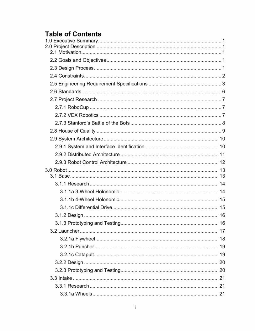
Table of Contents 1.0 Executive Summary ........................................................................................ 1 2.0 Project Description ......................................................................................... 1
2.1 Motivation .................................................................................................... 1
2.2 Goals and Objectives .................................................................................. 1
2.3 Design Process ........................................................................................... 1
2.4 Constraints .................................................................................................. 2
2.5 Engineering Requirement Specifications .................................................... 3
2.6 Standards .................................................................................................... 6
2.7 Project Research ........................................................................................ 7
2.7.1 RoboCup .............................................................................................. 7
2.7.2 VEX Robotics ....................................................................................... 7
2.7.3 Stanford’s Battle of the Bots ................................................................. 8
2.8 House of Quality ......................................................................................... 9
2.9 System Architecture .................................................................................. 10
2.9.1 System and Interface Identification..................................................... 10
2.9.2 Distributed Architecture ...................................................................... 11
2.9.3 Robot Control Architecture ................................................................. 12
3.0 Robot ............................................................................................................ 13 3.1 Base .......................................................................................................... 13
3.1.1 Research ............................................................................................ 14
3.1.1a 3-Wheel Holonomic ....................................................................... 14
3.1.1b 4-Wheel Holonomic ....................................................................... 15
3.1.1c Differential Drive............................................................................ 15
3.1.2 Design ................................................................................................ 16
3.1.3 Prototyping and Testing ...................................................................... 16
3.2 Launcher ................................................................................................... 17
3.2.1a Flywheel ........................................................................................ 18
3.2.1b Puncher ........................................................................................ 19
3.2.1c Catapult ......................................................................................... 19
3.2.2 Design ................................................................................................ 20
3.2.3 Prototyping and Testing ...................................................................... 20
3.3 Intake ........................................................................................................ 21
3.3.1 Research ............................................................................................ 21
3.3.1a Wheels .......................................................................................... 21

ii
3.3.1b Conveyor Belt ............................................................................... 22
3.3.1c Telescopic Lift ............................................................................... 22
3.3.2 Design ................................................................................................ 22
3.3.3 Prototyping and Testing ...................................................................... 22
3.4 Motor Controller Array ............................................................................... 23
3.4.1 Research ............................................................................................ 23
3.4.1a L298P ........................................................................................... 23
3.4.1b TB6612 ......................................................................................... 23
3.4.1c A4988 ............................................................................................ 23
3.4.1d PCA9685 ...................................................................................... 23
3.4.2 Design ................................................................................................ 24
3.4.3 Prototyping and Testing ...................................................................... 24
3.5 Microcontroller .......................................................................................... 25
3.5.1 Research ............................................................................................ 25
3.5.1a Arduino Uno (Atmel ATMega328P) ............................................... 27
3.5.1b Arduino MEGA (Atmel ATmega2560) ........................................... 27
3.5.1c TI Launchpad (MSP430G2553) .................................................... 27
3.5.2 Design ................................................................................................ 27
3.5.3 Prototyping and Testing ...................................................................... 27
3.6 Communication ......................................................................................... 27
3.6.1 Research ............................................................................................ 28
3.6.1a Bluetooth ....................................................................................... 28
3.6.1b Wi-Fi Direct ................................................................................... 28
3.6.1c Wi-Fi .............................................................................................. 28
3.6.2 Design ................................................................................................ 28
3.6.3 Prototyping and Testing ...................................................................... 28
3.7 Battery....................................................................................................... 29
3.7.1 Research ............................................................................................ 29
3.7.1a Lithium Polymer ............................................................................ 29
3.7.1b Nickle Cadmium ............................................................................ 30
3.7.1c Lead Acid ...................................................................................... 30
3.7.2 Design ................................................................................................ 30
3.7.3 Prototyping and Testing ...................................................................... 30
3.8 DC-DC Converter ...................................................................................... 30

iii
3.8.1 Research ............................................................................................ 31
3.8.1a TI Webench .................................................................................. 31
3.8.2 Design ................................................................................................ 31
3.8.3 Prototyping and Testing ...................................................................... 31
3.9 PCB........................................................................................................... 31
3.9.1 Research ............................................................................................ 32
3.9.1a Autodesk Eagle CAD .................................................................... 32
3.9.1b Diptrace ........................................................................................ 32
3.9.1c AutoCAD Electrical ........................................................................ 32
3.9.2 Design ................................................................................................ 32
3.9.3 Prototyping and Testing ...................................................................... 33
3.10 Software .................................................................................................. 33
3.10.1 Research .......................................................................................... 34
3.10.1a Arduino IDE vs Atmel Studio ....................................................... 34
3.10.1b Libraries ...................................................................................... 34
3.10.1c Interrupts ..................................................................................... 34
3.10.1d Real-Time programming ............................................................. 34
3.10.2 Design .............................................................................................. 34
3.10.3 Prototyping and Testing .................................................................... 34
4.0 Arena ............................................................................................................ 36 4.1 Frame........................................................................................................ 37
4.1.1 Research ............................................................................................ 37
4.1.1a PVC .............................................................................................. 37
4.1.1b Metal ............................................................................................. 37
4.1.1c Wood ............................................................................................. 37
4.1.2 Design ................................................................................................ 37
4.1.3 Prototyping and Testing ...................................................................... 39
4.2 Walls ......................................................................................................... 39
4.2.1 Research ............................................................................................ 40
4.2.1a Clear Acrylic Plastic ...................................................................... 40
4.2.1b Clear Vinyl Plastic ......................................................................... 40
4.2.1c Mesh ............................................................................................. 40
4.2.2 Design ................................................................................................ 41
4.2.3 Prototyping and Testing ...................................................................... 41
4.3 Court ......................................................................................................... 41

iv
4.3.1 Research ............................................................................................ 41
4.3.1a Laminate ....................................................................................... 41
4.3.1b Metal ............................................................................................. 41
4.3.1c Particle Board................................................................................ 42
4.3.2 Design ................................................................................................ 42
4.3.3 Prototyping and Testing ...................................................................... 42
4.4 Ball ............................................................................................................ 42
4.4.1 Research ............................................................................................ 42
4.4.1a Ping Pong Ball .............................................................................. 42
4.4.1b Small Tennis Ball .......................................................................... 42
4.4.2 Design ................................................................................................ 43
4.4.3 Prototyping and Testing ...................................................................... 43
4.5 Hoop ......................................................................................................... 43
4.5.1 Research ............................................................................................ 44
4.5.1a 3D Print ......................................................................................... 44
4.5.2b Metal ............................................................................................. 44
4.5.1c Infrared Gate ................................................................................. 44
4.5.1d Ultrasonic ...................................................................................... 44
4.5.1e Limit Switch ................................................................................... 44
4.5.2 Design ................................................................................................ 44
4.5.3 Prototyping and Testing ...................................................................... 44
4.6 Display and Sounds .................................................................................. 44
4.6.1 Research ............................................................................................ 45
4.6.1a Monitor .......................................................................................... 45
4.6.1b Speakers ....................................................................................... 46
4.6.2 Design ................................................................................................ 46
4.6.3 Prototyping and Testing ...................................................................... 46
4.7 Camera ..................................................................................................... 46
4.7.1 Research ............................................................................................ 47
4.7.1a Pixy ............................................................................................... 47
4.7.1b Logitech C922x ............................................................................. 47
4.7.1c Logitech C920 ............................................................................... 47
4.7.2 Design ................................................................................................ 47
4.7.3 Prototyping and Testing ...................................................................... 47

v
4.8 Gamepad .................................................................................................. 48
4.8.1 Research ............................................................................................ 48
4.8.1a Xbox One ...................................................................................... 48
4.8.1b PlayStation 4 ................................................................................. 48
4.8.2 Design ................................................................................................ 48
4.8.3 Prototyping and Testing ...................................................................... 49
4.9 LED Lights ................................................................................................ 49
4.9.1 Research ............................................................................................ 50
4.9.1a Adafruit NeoPixel .......................................................................... 50
4.9.1b Traditional LEDs ........................................................................... 50
4.9.2 Design ................................................................................................ 50
4.9.3 Prototyping and Testing ...................................................................... 50
4.10 Controller ................................................................................................ 50
4.10.1 Research .......................................................................................... 51
4.10.1a Raspberry Pi 3 Model B+ ............................................................ 51
4.10.1b Jetson Nano ................................................................................ 51
4.10.2 Design .............................................................................................. 51
4.10.3 Prototyping and Testing .................................................................... 51
4.11 Communication ....................................................................................... 51
4.11.1 Research .......................................................................................... 52
4.11.1a Intel Wireless-AC Wi-Fi/BT adapter ............................................ 52
4.11.2 Design .............................................................................................. 52
4.11.3 Prototyping and Testing .................................................................... 52
4.12 AC-DC Adapter ....................................................................................... 52
4.12.1 Description ....................................................................................... 53
1.12.2 Research ..................................................................................... 53
4.12.3 Design .............................................................................................. 53
4.12.4 Prototyping and Testing .................................................................... 53
4.13 DC-DC Converter .................................................................................... 53
4.13.1 Research .......................................................................................... 54
4.13.1a TI Webench ................................................................................ 54
4.13.2 Design .............................................................................................. 54
4.13.3 Prototyping and Testing .................................................................... 54
4.14 PCB......................................................................................................... 54

vi
4.14.1 Research .......................................................................................... 55
4.14.1a Autodesk Eagle CAD .................................................................. 55
4.14.1b DipTrace ..................................................................................... 55
4.14.1c AutoCAD Electrical ...................................................................... 55
4.14.2 Design .............................................................................................. 55
4.14.3 Prototyping and Testing .................................................................... 55
4.15 Computer Vision ..................................................................................... 55
4.15.1 Research .......................................................................................... 56
4.15.1a OpenCV ...................................................................................... 56
4.15.1b Neural Net ................................................................................... 56
4.15.2 Design .............................................................................................. 56
4.15.3 Prototyping and Testing .................................................................... 56
4.16 Peripheral Software ................................................................................ 57
4.16.1 Research .......................................................................................... 57
4.16.1a C++ ............................................................................................. 57
4.16.2 Design .............................................................................................. 58
4.16.3 Prototyping and Testing .................................................................... 58
5.0 Game System ............................................................................................... 58 5.1 Game Engine ............................................................................................ 59
5.1.1 Research ............................................................................................ 59
5.1.1a Unity .............................................................................................. 59
5.1.1b Godot ............................................................................................ 60
5.1.2 Design ................................................................................................ 60
5.1.3 Prototyping and Testing ...................................................................... 60
5.2 Collision Detection .................................................................................... 61
5.2.1 Research ............................................................................................ 61
5.2.1a Game-Engine Collision Detection ................................................. 61
5.2.2 Design ................................................................................................ 61
5.2.3 Prototyping and Testing ...................................................................... 61
5.3 Video Playback ......................................................................................... 61
5.3.1 Research ............................................................................................ 62
5.3.2 Design ................................................................................................ 62
5.3.3 Prototyping and Testing ...................................................................... 62
6.0 Subsystem Integration .................................................................................. 62 6.1 Base – Intake ............................................................................................ 62

vii
6.1.1 Design ................................................................................................ 63
6.1.2 Prototype and Testing ........................................................................ 63
6.2 Base – Launcher ....................................................................................... 63
6.2.1 Design ................................................................................................ 63
6.2.2 Prototype and Testing ........................................................................ 63
6.3 Intake – Launcher ..................................................................................... 63
6.3.1 Design ................................................................................................ 64
6.3.2 Prototype and Testing ........................................................................ 64
6.4 Arena – Game ........................................................................................... 64
6.4.1 Design ................................................................................................ 64
6.4.2 Prototyping and Testing ...................................................................... 64
6.5 Robot - Arena ............................................................................................ 65
6.5.1 Design ................................................................................................ 65
6.5.2 Prototype and Testing ........................................................................ 65
7.0 Administrative ............................................................................................... 65 7.1 Budget and Bill of Materials ...................................................................... 65
7.2 Milestones ................................................................................................. 67
7.3 Communication ......................................................................................... 68
7.3.1 Microsoft SharePoint .......................................................................... 69
7.3.2 Discord ............................................................................................... 69
7.3.3 GitHub ................................................................................................ 69
8.0 Project Summary and Conclusion ................................................................ 69 9.0 Appendices ................................................................................................... 69
9.1 Copyright Permissions .............................................................................. 69
9.2 Data Sheets .............................................................................................. 70
Table of Figures Figure 1 Project Design Process .......................................................................... 2 Figure 2 Typical RoboCup arena setup ................................................................ 7 Figure 3 House of Quality ..................................................................................... 9 Figure 4 System Hierarchy and Interface Identification ...................................... 11 Figure 5 System Communication Diagram ......................................................... 12 Figure 6 Deliberative Robot Architecture introduced by Rodney A. Brooks ........ 12 Figure 7 Robot Subsystem Power and Signal Diagram ...................................... 13 Figure 8 Example Omni-wheel base from Heneng on Amazon Product Page ... 14 Figure 9 Example holonomic configuration. Image from Robotshop .................. 15 Figure 10 4-Wheel Holonomic from Yale Page .................................................. 15 Figure 11 2 Wheel Differential from Savagemaker tutorial ................................. 16

viii
Figure 12 Arena Subsystem Power and Signal Diagram .................................... 37 Figure 13 SOLIDWORKS Image of proposed scale Arena, Robot, and Ball ...... 39 Figure 14 KONG basketball tennis ball chosen for this project from Amazon .... 43 Figure 15 Game system block diagram .............................................................. 59 Figure 16 Gantt Chart indicating critical milestones and work timelines ............. 68 Table of Tables Table 1 Project constraints ................................................................................... 2 Table 2 Arena constraints ..................................................................................... 2 Table 3 Robot constraints ..................................................................................... 3 Table 4 Game constraints .................................................................................... 3 Table 5 Project requirements................................................................................ 3 Table 6 Robot requirements ................................................................................. 3 Table 7 Arena requirements ................................................................................. 5 Table 8 Game requirements ................................................................................. 6 Table 9 Relevant Standards ................................................................................. 6 Table 10 Base Design Comparison .................................................................... 16 Table 11 Base Tests ........................................................................................... 17 Table 12 Flywheel design problems ................................................................... 18 Table 13 Launcher Tests .................................................................................... 20 Table 14 Intake Tests ......................................................................................... 23 Table 15 Table of Motor Controller Tests ........................................................... 24 Table 16: Compare and Contrast of Different Microcontroller Technologies ...... 26 Table 17 Controller tests .................................................................................... 27 Table 18 Communication tests ........................................................................... 29 Table 19 Battery tests ......................................................................................... 30 Table 20 DC-DC Converter tests ........................................................................ 31 Table 21 I/O Schedule ........................................................................................ 32 Table 22 Robot PCB Tests ................................................................................. 33 Table 23 Software System Tests ........................................................................ 34 Table 24 Frame Tests ........................................................................................ 39 Table 25 Wall testing .......................................................................................... 41 Table 26 Court Testing ....................................................................................... 42 Table 27 Ball Tests ............................................................................................. 43 Table 28 Hoop Tests .......................................................................................... 44 Table 29: Display and Sound Test ...................................................................... 46 Table 30 Camera tests ....................................................................................... 47 Table 31 Player input functions and gamepad mapping ..................................... 49 Table 32 Gamepad tests .................................................................................... 49 Table 33 LED Lights tests .................................................................................. 50 Table 34 Controller tests .................................................................................... 51 Table 35 Communication tests ........................................................................... 52 Table 36 Power Requirement Calculation .......................................................... 53 Table 37 AC-DC Convertor Tests ....................................................................... 53 Table 38 DC-DC Converter tests ........................................................................ 54 Table 39 Arena I/O Schedule ............................................................................. 55

ix
Table 40 PCB Tests ........................................................................................... 55 Table 41 Computer Vision Tests ........................................................................ 56 Table 42 Peripheral Software tests ..................................................................... 58 Table 43 Game engine tests............................................................................... 60 Table 44 Collision Detection Tests ..................................................................... 61 Table 45 Video Playback tests ........................................................................... 62 Table 46 Base-Intake integration tests ............................................................... 63 Table 47 Base-Launcher Integration tests .......................................................... 63 Table 48 Intake-Launcher Integration Tests ....................................................... 64 Table 49 Arena-Game Integration Tests ............................................................ 64 Table 50 Robot-Arena Integration Tests ............................................................. 65 Table 51 Robot Budget ....................................................................................... 65 Table 52 Arena Budget ....................................................................................... 66 Table 53 Bill of Materials for Project ................................................................... 66 Table 54 Bill of Materials for Manufacturing and Reproducing ........................... 67
1
1.0 Executive Summary 2.0 Project Description 2.1 Motivation Entertainment is an essential part of life in the City of Orlando. Amusement parks, arcades, sports, movies and television retire us of our tiredness and fulfill our lives with optimism and sheer excitement. The Robot Basketball game project is chosen to create dynamic, interactive entertainment for everyone to enjoy. This project is proposed in the spirit of Robocup challenge; Robocup is a standardized soccer-based robotic competition with a variety of leagues. In general, robots compete against one another utilizing complex algorithms developed by engineers. In the case of Robot Basketball, two human players can compete against one another by controlling the robot to move and shoot the basketball. However, due to perception and coordination problems that come from remotely operating robots, the players may need some assistance to maximize amusement. This introduces a complex engineering challenge that involves some level of machine intelligence to achieve high control fidelity. The team proposes this project as a foundation for learning a wide variety of skills including Robotics, Computer Vision, Machine Learning, PCB Design, Bluetooth communication, Game and App development, and real-time control. 2.2 Goals and Objectives The overall goal in this project is to create an arcade-style entertainment system that is both robust and intelligent. The product should be able to fit on typical foldable tables and should be playable by at least one, but preferably two people. The system should be designed modularly such that different subsystems can be designed, tested, and created independently without disassembling the entire system. The system should incorporate both high level software and low-level hardware interfacing. The robot should be low cost such that multiple robots can be created. The robot should be capable of collecting and launching the ball into a scale hoop with high accuracy and precision. The robot should be quick to traverse the court to increase mid-game activity. The system should assist the player by performing calculations to increase shot accuracy. The arena should display information to the player including game type, score, and debugging information. The final product should be engaging and attractive. 2.3 Design Process

2
The design process for this project follows the following pattern: Define the system features from market requirements, Define the subsystem components, Determine the requirements for each subsystem requirement specifications, define the tests to evaluate the subsystem requirement specifications, research components, design subsystem, prototype subsystem, and test subsystem. This pattern is chosen because it follows the logical progression of system development such that a final product meets the actual market requirements defined by customer. Each test defined early in the process is directly traceable to an engineering requirement specification. The tests are defined before the design is complete in order to create an objective set of tasks to be completed such that the requirements are fully satisfied. This prevents changing tests in order to ensure the test passes.
Figure 1 Project Design Process
2.4 Constraints These constraints are those placed upon the project by environmental factors such as transportation, budget, or customer requirements. The constraints arise from the need to present the project in appropriate settings, and also to constrain the team adhere to deadlines and restrictions placed upon the project by the senior design committee.
Table 1 Project constraints Constraint The project shall…
C.P.1 Cost no more than $1000
C.P.2 Be transportable in a standard-sized sedan
C.P.3 Be designed by August 2, 2019
C.P.4 Be built and tested by November 15, 2019
C.P.5 Utilize GitHub as a version control system
Table 2 Arena constraints Constraint The Arena shall…
C.A.1 Cost no more than $400

3
C.A.2 Be powered by a standard US 120V 60Hz wall outlet
C.A.3 Be able to rest on two standard folding tables
C.A.4 Utilize a custom PCB that fits within size constraints required by the project
C.A.5 Utilize a PCB that contains limited through-hole soldering
Table 3 Robot constraints Constraint The Robot(s) shall…
C.R.1 Cost no more than $300
C.R.2 Utilize a custom PCB that fits within size constraints required by the project
C.R.3 Utilize a PCB that contains limited through-hole soldering
C.R.4 Be powered by a battery
Table 4 Game constraints
Constraint The Game shall… C.G.1 Cost $0
C.G.2 Utilize a market-available Game Engine
2.5 Engineering Requirement Specifications The Engineering Requirement specifications found in the following tables are requirements developed by the project team such that the project is fully defined and constrained. The requirements are a guiding force behind the entire project, and each design decision made in the following sections are traceable back to these defined requirements.
Table 5 Project requirements Requirement The project shall…
R.P.1 Contain three high-level subsystems capable of communication: Arena, Robot, and Game
R.P.2 Allow a human-player to control the robot-subsystem to drive and launch a ball
R.P.3 Take efforts to ensure safety of both human players and subsystems
R.P.4 Identify high-risk interfaces and fully define & design them
Table 6 Robot requirements
Requirement The Robot(s) shall… R.R.1 Weigh no more than 8 lbs.

4
R.R.2 Communicate with the arena subsystem at a rate of at least 30Hz
R.R.3 Be capable of holonomic locomotion
R.R.4 Contain at least 3 Drive motors
R.R.5 Contain no more than two motors for launching mechanism
R.R.6 Contain a launching mechanism capable of launching a 1.5” diameter rubber ball
R.R.7 Contain an intake mechanism for acquiring a 1.5” diameter rubber ball from ground level
R.R.8 Traverse in one direction at minimum 0.3 m/s
R.R.9 Be powered by a 12V battery
R.R.10 Convert voltage from 12V DC to 9V DC, 7.2V DC and 5V DC with high efficiency
R.R.11 Support an embedded controller capable of processing controls for a minimum 6 motors
R.R.12 Maintain at least 75% shot accuracy from anywhere on the court
R.R.13 Traverse the court without unintentional slipping
R.R.14 Be able to maintain a shot angle while driving
R.R.15 Be sturdy, robust, and resilient regardless of subsystem weight
R.R.16 Perform required functionality regardless of ball holding status
R.R.17 Be resilient to hitting the ball while driving
R.R.18 Be resilient to collisions
R.R.19 Be capable of launching a ball with different forces for a required distance
R.R.20 Intake the ball while stationary and moving from a variety of angles
R.R.21 Utilize a microcontroller capable of I2C, SPI and UART communication protocols
R.R.22 Utilize sensor data to close feedback loops on relevant actuators at a reasonable update rate
R.R.23 Utilize a battery that can safely operate at the loads required for the systems
R.R.24 Utilize software that is fully unit tested
R.R.25 Utilize a robust deterministic state-machine
R.R.26 Be power efficient in operation to run more than 10 minutes
5
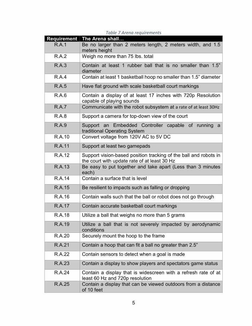
Table 7 Arena requirements Requirement The Arena shall…
R.A.1 Be no larger than 2 meters length, 2 meters width, and 1.5 meters height
R.A.2 Weigh no more than 75 lbs. total
R.A.3 Contain at least 1 rubber ball that is no smaller than 1.5” diameter
R.A.4 Contain at least 1 basketball hoop no smaller than 1.5” diameter
R.A.5 Have flat ground with scale basketball court markings
R.A.6 Contain a display of at least 17 inches with 720p Resolution capable of playing sounds
R.A.7 Communicate with the robot subsystem at a rate of at least 30Hz
R.A.8 Support a camera for top-down view of the court
R.A.9 Support an Embedded Controller capable of running a traditional Operating System
R.A.10 Convert voltage from 120V AC to 5V DC
R.A.11 Support at least two gamepads
R.A.12 Support vision-based position tracking of the ball and robots in the court with update rate of at least 30 Hz
R.A.13 Be easy to put together and take apart (Less than 3 minutes each)
R.A.14 Contain a surface that is level
R.A.15 Be resilient to impacts such as falling or dropping
R.A.16 Contain walls such that the ball or robot does not go through
R.A.17 Contain accurate basketball court markings
R.A.18 Utilize a ball that weighs no more than 5 grams
R.A.19 Utilize a ball that is not severely impacted by aerodynamic conditions
R.A.20 Securely mount the hoop to the frame
R.A.21 Contain a hoop that can fit a ball no greater than 2.5”
R.A.22 Contain sensors to detect when a goal is made
R.A.23 Contain a display to show players and spectators game status
R.A.24 Contain a display that is widescreen with a refresh rate of at least 60 Hz and 720p resolution
R.A.25 Contain a display that can be viewed outdoors from a distance of 10 feet

6
R.A.26 Have speakers capable of being heard from 10ft away
R.A.27 Contain LED lights for status indication and consistent lighting on the court
R.A.28 Utilize an AC-DC adapter capable of powering the required DC loads at a high efficiency
R.A.29 Contain a DC-DC adapter that converts from the voltage provided by the AC-DC adapter to the required DC voltages at a high efficiency
R.A.30 Contain software that is fully unit tested
Table 8 Game requirements
Requirement The Game shall… R.G.1 Create a 2D visual representation of the Arena and Robot Status
R.G.2 Have a menu to start, pause, and reset a timed match
R.G.3 Display current score and game time
R.G.4 Playback past 10 seconds of gameplay upon a goal
R.G.5 Play a 3D animation of the ball making it into the goal
R.G.6 Perform collision detection between the different objects
R.G.7 Employ software that is fully unit tested
R.G.8 Utilize collision detection to prevent dangerous actions
2.6 Standards The standards found below are relevant engineering standards that can simplify or increase the capabilities of the designs chosen. Utilizing standards results in inter-operability between various systems. It also streamlines decision designs in the event of an available standard that meets requirements.
Table 9 Relevant Standards Standard Name/Field ICS 29.020 Electrical Engineering ICS 29.060 Electrical wires and cables ICS 29.100 Components for electrical equipment IEEE 1872-2015 Standard for Ontologies for Robotics and Automation IEEE 1012-2016 Standard for System, Software, and Hardware Verification
and validation IEEE/ISO/IEC 29418-2018
International standard – Systems and software engineering – Life cycle processes – Requirements engineering
IEEE 802.15.1 Bluetooth qualification IEEE/EIA 12207 Life Cycle Process
7
IEEE 1540 Software Risk Management IEEE 1471 Recommended Practice for Architectural Description of
Software -intensive systems ISO/IEC 14882 Programming Language C++ Unicode 12.1.0 Unicode standard ICS 31.020 Electronic components in general ICS 31.180 Printed circuits and boards ISO 3833-1977 Road vehicles – Types – Terms and definitions
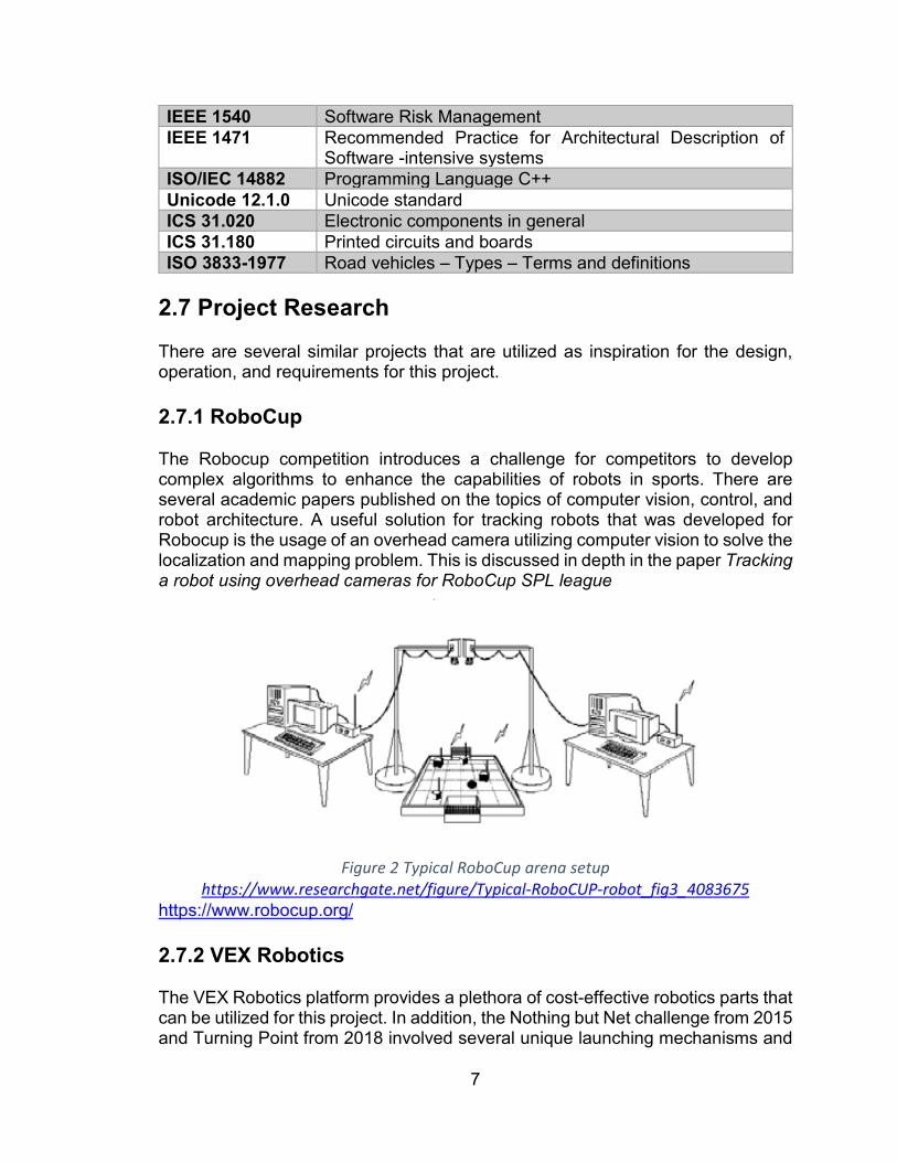
2.7 Project Research There are several similar projects that are utilized as inspiration for the design, operation, and requirements for this project. 2.7.1 RoboCup The Robocup competition introduces a challenge for competitors to develop complex algorithms to enhance the capabilities of robots in sports. There are several academic papers published on the topics of computer vision, control, and robot architecture. A useful solution for tracking robots that was developed for Robocup is the usage of an overhead camera utilizing computer vision to solve the localization and mapping problem. This is discussed in depth in the paper Tracking a robot using overhead cameras for RoboCup SPL league
Figure 2 Typical RoboCup arena setup
https://www.researchgate.net/figure/Typical-RoboCUP-robot_fig3_4083675 https://www.robocup.org/ 2.7.2 VEX Robotics The VEX Robotics platform provides a plethora of cost-effective robotics parts that can be utilized for this project. In addition, the Nothing but Net challenge from 2015 and Turning Point from 2018 involved several unique launching mechanisms and

8
locomotion systems for a basketball-like challenge. The Vex robotics platform is a starting place for the mechanical aspects of the robot. The challenge provides a plethora of designs for launching a ball at different forces and ranges, and an inordinate amount of designs for locomotion in a competitive arena. https://www.youtube.com/watch?v=A8daR6qBw3M) 2.7.3 Stanford’s Battle of the Bots Stanford’s 2015 battle of the bots. This challenge very closely matches the scope and scale of our project. The students developed many unique robots that launch balls in a basketball competition at a very similar scale to the one initially considered for this project. This challenge provides a point of comparison for the scale, size, and capabilities for launching a small tennis ball in a basketball context. https://www.youtube.com/watch?v=fXsB7fXcWO8.

9
2.8 House of Quality The house of quality diagram shown in Figure 3 indicates the relationships between engineering requirements and market requirements. Additionally, the diagram indicates the relationship between different engineering requirements. In summary, some requirements that should be maximized causes an increase in a requirement that should be minimized. For example, increasing the shot accuracy of the project would result in an increased cost of the project.
Figure 3 House of Quality

10
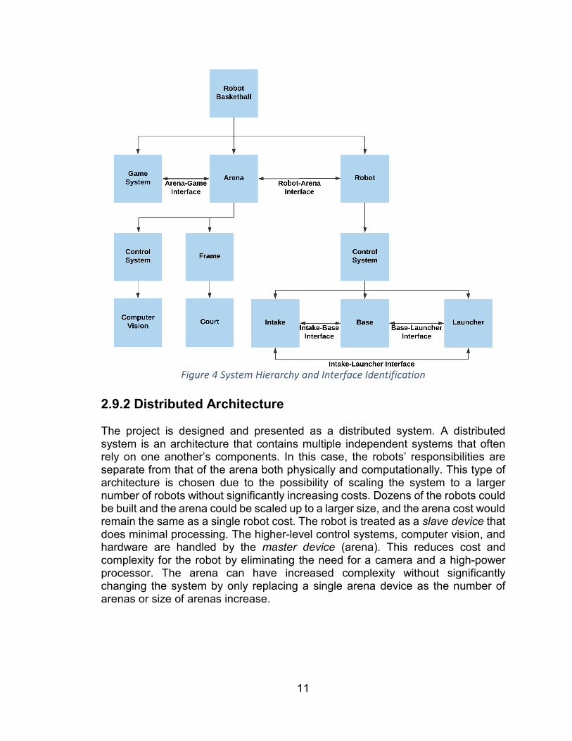
2.9 System Architecture The system architecture defines the various systems included in the project, and their interactions between one another. The architecture is the highest-level guiding structure for all solutions to the engineering requirement specifications for both hardware and software systems. 2.9.1 System and Interface Identification The Project is split into three primary systems: Arena, Robot, and Game. The Arena system encompasses all things related to the basketball court, basketball, physical frame structure, and computer vision. The arena contains a control system for high-level planning and control for commands that are sent to the robot system. The Computer vision subsystem is to determine the position and orientation of the robot on the court. Additionally, it must track the position of the ball on the court. The Game System involves taking data in from the player and displaying information such as game and robot status, instant replays, and other high-level functionality. The robot system is the device for physically interacting with the basketball court and basketball. The robot receives commands from the arena control-system and executes them. The subsystems identified to achieve the requirements are the mobile base, intake, launcher, and control subsystems. These systems are discussed in depth in the subsequent diagrams. There are several critical interfaces identified for this project. These are looked at separately from their own subsystem such that the individual subsystems can be designed independently. However, this introduces risk that the systems are not compatible. Further, interesting behaviors can emerge when complex systems are put together. Thus, these integration systems are fully designed and tested in conjunction with the individual systems to ensure robustness and consistency.
11
Figure 4 System Hierarchy and Interface Identification
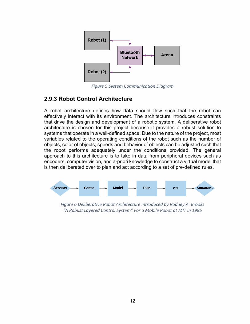
2.9.2 Distributed Architecture The project is designed and presented as a distributed system. A distributed system is an architecture that contains multiple independent systems that often rely on one another’s components. In this case, the robots’ responsibilities are separate from that of the arena both physically and computationally. This type of architecture is chosen due to the possibility of scaling the system to a larger number of robots without significantly increasing costs. Dozens of the robots could be built and the arena could be scaled up to a larger size, and the arena cost would remain the same as a single robot cost. The robot is treated as a slave device that does minimal processing. The higher-level control systems, computer vision, and hardware are handled by the master device (arena). This reduces cost and complexity for the robot by eliminating the need for a camera and a high-power processor. The arena can have increased complexity without significantly changing the system by only replacing a single arena device as the number of arenas or size of arenas increase.
12
Figure 5 System Communication Diagram
2.9.3 Robot Control Architecture A robot architecture defines how data should flow such that the robot can effectively interact with its environment. The architecture introduces constraints that drive the design and development of a robotic system. A deliberative robot architecture is chosen for this project because it provides a robust solution to systems that operate in a well-defined space. Due to the nature of the project, most variables related to the operating conditions of the robot such as the number of objects, color of objects, speeds and behavior of objects can be adjusted such that the robot performs adequately under the conditions provided. The general approach to this architecture is to take in data from peripheral devices such as encoders, computer vision, and a-priori knowledge to construct a virtual model that is then deliberated over to plan and act according to a set of pre-defined rules.
Figure 6 Deliberative Robot Architecture introduced by Rodney A. Brooks
“A Robust Layered Control System” For a Mobile Robot at MIT in 1985

13
3.0 Robot The robot subsystem is comprised of all the components required to pick up and launch a ball from different places on the court. The diagram in Figure 7 denotes the primary systems and their various connections to other systems.
Figure 7 Robot Subsystem Power and Signal Diagram
3.1 Base The mobile robot base is the locomotion piece of the system. It is the sole source of robot movement on the court. The mobile base is to be fast and agile in order to increase player engagement. If the robot is slow, the player will feel like they are not in control of the robot’s actions, and they are not excited to play the game. If
14
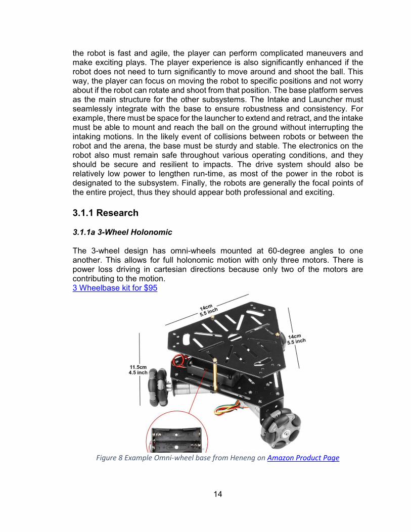
the robot is fast and agile, the player can perform complicated maneuvers and make exciting plays. The player experience is also significantly enhanced if the robot does not need to turn significantly to move around and shoot the ball. This way, the player can focus on moving the robot to specific positions and not worry about if the robot can rotate and shoot from that position. The base platform serves as the main structure for the other subsystems. The Intake and Launcher must seamlessly integrate with the base to ensure robustness and consistency. For example, there must be space for the launcher to extend and retract, and the intake must be able to mount and reach the ball on the ground without interrupting the intaking motions. In the likely event of collisions between robots or between the robot and the arena, the base must be sturdy and stable. The electronics on the robot also must remain safe throughout various operating conditions, and they should be secure and resilient to impacts. The drive system should also be relatively low power to lengthen run-time, as most of the power in the robot is designated to the subsystem. Finally, the robots are generally the focal points of the entire project, thus they should appear both professional and exciting. 3.1.1 Research 3.1.1a 3-Wheel Holonomic The 3-wheel design has omni-wheels mounted at 60-degree angles to one another. This allows for full holonomic motion with only three motors. There is power loss driving in cartesian directions because only two of the motors are contributing to the motion. 3 Wheelbase kit for $95
Figure 8 Example Omni-wheel base from Heneng on Amazon Product Page

15
Figure 9 Example holonomic configuration. Image from Robotshop
3.1.1b 4-Wheel Holonomic The 4-Wheel Holonomic design is the same in principle as the design discussed in 3.1.1a 3-Wheel Holonomic. However, instead of three wheels at 60-degree angles, there are 4 wheels mounted at 45-degree angles. There is significantly more power in this design than in the three-wheel design because all four wheels are contributing to the motion at any given time. Additionally, the output speed is faster than the actual wheel rpm due to vector multiplication at the cost of torque. 4-Wheel Holonomic kit for $276 from Robotshop
Figure 10 4-Wheel Holonomic from Yale Page
3.1.1c Differential Drive The differential drive design is a traditional approach to mobile robotic bases. This design generally involves 2 to 4 wheels mounted square to the base. Either two or
16
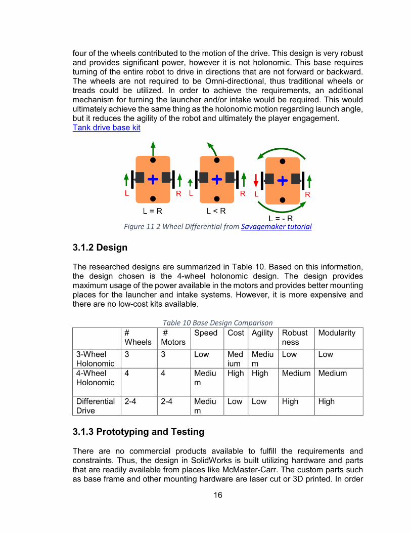
four of the wheels contributed to the motion of the drive. This design is very robust and provides significant power, however it is not holonomic. This base requires turning of the entire robot to drive in directions that are not forward or backward. The wheels are not required to be Omni-directional, thus traditional wheels or treads could be utilized. In order to achieve the requirements, an additional mechanism for turning the launcher and/or intake would be required. This would ultimately achieve the same thing as the holonomic motion regarding launch angle, but it reduces the agility of the robot and ultimately the player engagement. Tank drive base kit
Figure 11 2 Wheel Differential from Savagemaker tutorial
3.1.2 Design The researched designs are summarized in Table 10. Based on this information, the design chosen is the 4-wheel holonomic design. The design provides maximum usage of the power available in the motors and provides better mounting places for the launcher and intake systems. However, it is more expensive and there are no low-cost kits available.
Table 10 Base Design Comparison #
Wheels # Motors
Speed Cost Agility Robustness
Modularity
3-Wheel Holonomic
3 3 Low Medium
Medium
Low Low
4-Wheel Holonomic
4 4 Medium
High High Medium Medium
Differential Drive
2-4 2-4 Medium
Low Low High High
3.1.3 Prototyping and Testing There are no commercial products available to fulfill the requirements and constraints. Thus, the design in SolidWorks is built utilizing hardware and parts that are readily available from places like McMaster-Carr. The custom parts such as base frame and other mounting hardware are laser cut or 3D printed. In order

17
to prototype one robot, two 3-wheel kits are purchased. In order to prototype two robots, three 3-wheel kits are purchased.
Table 11 Base Tests Requirement Test Required Equipment R.R.13 Does the base traverse the court
without slipping Court, rope
R.R.14 Does the base drive forward, backward, left, right, and rotate in both directions
Arduino, long USB cable, windows laptop
R.R.15 Is the base plate sturdy enough to support the additional weights of the other subsystems
Weight
R.R.15 The base is heavy enough to support a moment about the expected launching axis
Weights
R.R.15 Does the base move in all directions when additional load is added
Arduino, long USB cable, windows laptop,
R.R>20 Does the base have enough height for the ball to roll underneath on the side that the intake is mounted to
Ball
R.R.20 Does the base have low enough height to block the ball from rolling under on the sides that the intake is not mounted
Ball
R.R.15 Does the robot remain active after an impact
3.2 Launcher The launcher on the robot must be able to shoot the ball from anywhere on the court being played on. In order to accomplish this, the launching mechanism must be adjustable in some way, shape or form. This feat can be accomplished in a multitude of ways, however, to make it an achievable goal, the team narrowed the possible designs down to two ways: either lock the angle and have variable force or lock the force and adjust the angle. These paths require different solutions and steps to be able to work properly, and the same type of mechanism may not work for both, or either of the ways chosen by the team and can influence other design choices. With a fixed angle, the force of the mechanism must be able to be easily and reliably changed. This makes the overall mechanism more complicated because more parts are required to make the launcher behave in the intended manner. A fixed force and variable angle bring up a different set of problems, such as the platform the launcher rests on will need to be more complicated instead of the launcher itself, and the equations become more complicated due to the changing height at each point of launch. Another point the team must keep in mind is that due to the steeper angle that would be required at some points on the field, the ceiling must be higher than it would be with a fixed angle. As previously

18
mentioned, this would have an influence on the size and weight of the field, which has the potential to clash with our field requirements. The three main ways of implementing a launcher on the robot being explored are a flywheel, puncher, and catapult. These three methods were chosen because most of the ways to launch the ball reasonably will fit into one of these categories and the team can narrow it down more easily within the category before deciding which type overall to use. 3.2.1a Flywheel There are two main ways to implement a flywheel launching mechanism, using one or two wheels. Both offer their own specific problems that must be considered when doing calculations for the projectile coming out of the launcher. These situations are outlined in Table 10 below.
Table 12 Flywheel design problems Flywheel problems Outcomes Wheel not up to full speed before shot Shot comes out short Ball enters wheel at different speed every shot
Shot is either short or long depending on speed and is hard to track and correct
Ball hits different part of wheel (isn’t compressed as much or compressed more)
Length of shot is once again affected. Could also put a different spin on the ball
Wheels are not spinning at same speed (double flywheel specific)
Curve is put on the ball. This could also potentially change every time the ball is fired.
All these situations boil down to a flywheel just being too unpredictable at any given time. There are ways to remedy these problems, such as finding ways to finely control the speed of the ball entering the wheel, making sure the channel the ball follows into the launcher is a tight fit for the ball to disallow the ball to enter the wheel from a different angle each shot. The solutions to many of the problems presented by a flywheel are mechanical in nature and are something that the team isn’t built to implement well. Something that can be looked at positively about using a flywheel, however, is that it will allow the robot to put a more natural spin on the ball compared to the other options under consideration by the team. Since a huge part of basketball is getting spin on the ball to help make shots off the backboard, this is a rather good thing to be able to do. The flywheel design also would easily be able to fulfill our requirements of varying force, by adjusting the velocity the wheel spins at, and the ability to fix the angle that the ball is launched at easily. This could be done the other way around rather easily as well. Comparing the two types of flywheels, one or two-wheel, both have their own advantages as well. A one-wheel flywheel will take up less space overall but won’t be able to put out the same force as a two-wheel flywheel using the same motors. Also, due to having only a single motor, the one-wheel flywheel solution would require less power to operate as well as have an overall simpler design to
19
implement. The two-wheel flywheel would allow for more finely tuned spin on the ball and more overall launching power. However, the extra motor would need extra consideration as it adds more weight to the robot in the form of extra parts needed to hold and support the extra motor and removes space needed to implement other systems on the robot. Depending on the parts chosen, this could put unnecessary strain on the base and could affect how the base is constructed. The two-wheel variant of the flywheel also has a greater chance of failing due to the extra wheel. This would require careful monitoring of more variables than the single wheel method as any sort of disharmony between the speed or angle of the two wheels essentially make the calculations done by the other systems of the project useless as the real-life motion of the ball wouldn’t be able to match the projected numbers. Overall, the flywheel method’s variability is both its biggest strength and weakness, in the form of being flexible enough to meet the team’s launcher requirements whichever way ultimately is chosen while being unreliable in accuracy and precision needed for this task. 3.2.1b Puncher A punching mechanism is a lot more straightforward than either a flywheel or catapult design. With a puncher there is a lot more control possible with it because the ball is always launched from the same spot and orientation every time. The first major downside of a puncher is that in order to make the force of it variable is to more hardware is required. If the team was going to make a fixed force mechanism for a shooter, the puncher would excel at that as it could be solved with a mechanism such as a skip gear. However, due to needing to meet the requirement of a variable force on the ball, an additional mechanism such as a linkage, actuator, or even another motor, would be required to release the puncher. The puncher design currently being considered will be a tension-based design powered by springs either extended or compressed with a sudden release. The spot that the puncher contacts the ball and the shape of the punch can be changed to produce different effects on the ball. Some examples of this are using a wedge and hitting low to produce a chip shot effect or to hit the ball as close to the center as possible to get little to no spin. As the puncher and rail can be attached at basically any angle and won’t need to move, the team can experiment easily and find the best angle to use before locking the angle in place to fulfil our requirement of having a fixed angle, variable force launcher. Due to the puncher traveling in a straight line and only acting a short impulse upon the ball, the calculations end up being basic projectile motion equations. 3.2.1c Catapult There are three main types of catapults, the ballista, the mangonel and the trebuchet. Since the construction of a trebuchet device would be unfeasible due to the complication of the design and the size constraint of our small robot, that idea was only very briefly explored. The ballista variant would be very similar in design

20
to the puncher mechanism described above in section 3.2.2b, except for the fact that the ball would be pushed down the length of rail instead of a short, sharp contact to propel the ball. The ballista design shares a lot of the same advantages and disadvantages as the puncher except for being able to control the spin of the ball as it is launched. And in the implementation that would be used for this robot, the only difference between the ballista design and the puncher design being considered is a stopper that keeps the ball from falling into the channel left behind when the spring is drawn back. The last type of catapult is the mangonel, which is what most people think of when they think of the word catapult. Using this design poses a lot of design problems. First, we would need to have a bigger and more complicated intake or put it in a place on the robot that doesn’t make sense in order to load the arm of the catapult. Second, there would be little control over the angle unless the placement of the beam to act as a brake for the arm was very precise. Due to this, if the team was to try to make the robot have a variable launch angle, this design would immediately become unable to use as it would be difficult to get the correct placement dynamically on such a small-scale base. The team would also have to take special care to make sure that the arm was able to be fully drawn back, or at least drawn pack to a specific spot to be able to vary the force. The calculations for aiming the catapult and getting the correct drawback on the arm are more calculated than the relatively easier impulse and standard projectile motion formulas useable with something like the puncher. 3.2.2 Design 3.2.3 Prototyping and Testing Prototyping for the launcher will mostly consist of keeping the same base of a tension-based spring device cranked by a motor attached to a gear. The base will initially be made of 3d printed parts for the rail and slide to guide and power the puncher. As it is found out that a specific design works, that part will either be bought of cut from a studier material than what a basic 3d printer can use as it will need to be one of the most resilient pieces on the robot. As more of the tests below in Table 11 are conducted, the springs will be changed out to change the force put on the ball or to be able to be stretched more or less for better control over the variable force of the spring. Fine control of the spring will also depend almost entirely on the quality of the encoders that are used for the gear that cranks the spring.
Table 13 Launcher Tests Requirement Test Required Equipment R.R.19
Test the launcher with different forces. Determine distance.
Tape measure, carbon paper
R.R.19
Test the launcher with different angles. Determine distance
Tape measure, carbon paper

21
R.R.12
Test the launcher for accuracy and precision at different shooting configurations
Tape measure Carbon paper
R.R.6 Test if launcher resets properly between shots
R.R.12
Check if the ball is hit consistently in the same area
R.R.9 R.R.10
Measure voltage and current draw across subsystem
3.3 Intake The intake for the robot must be able to pick up a ball and transfer it to the launcher mechanism. There are both passive and active options to pick up a ball that the team has explored. Passive solutions require no power, or significantly less power than active solutions, however, there is a higher chance for them to not consistently pick up the ball. Options researched for our intake mechanism include a telescopic lift, a conveyor belt, or a wheel-based design. This mechanism would place the ball directly into the spot it will be launched from. It’s important that the ball is deposited in the same spot each time because that has a direct impact on the accuracy and consistency of the launcher due to the puncher having to hit the same spot on the ball each time. The team has narrowed the decision down to a series of wheels, a conveyor belt, and a telescopic lift like what is seen on a forklift. 3.3.1 Research 3.3.1a Wheels The first design being considered, as well as the first of the two active intake mechanisms is a wheel-based mechanism to pick up the ball and pass it up the intake. Wheels for the intake can be done in two ways, either on one or both sides of a channel, much like a single or double flywheel design except with a lot less power. Wheels are more useful for the intake than for the launcher because less precision is required. The design and calculations for the intake don’t depend on something as small as making sure the ball comes in at the same speed every time. Since all that is required is to get the ball to the launcher, using wheels is necessary. A wheel-based intake mechanism would most likely require the most hardware out of all the designs being considered as it would require more than one motor to implement. The wheel design the team is looking at is essentially a conveyor belt without the belt and the only major drawback besides the aspect of having to utilize more hardware is that if the wheels aren’t placed in the right position the ball could get stuck between them or not move quick enough. Due to each wheel needing to be mounted individually, there is also more potential for a part to fail taking down the entire mechanism. The front of the wheels act as an active intake by spinning to physically pull in the balls, instead of just corralling the ball.
22
3.3.1b Conveyor Belt The second active design being considered is a conveyor belt. There are only two versions of the conveyor belt that can be implemented for the robot. One with, and one without dividers in it. The only real distinction is that the one with tabs will have a more redundant mechanism for carrying the ball to the launcher. A conveyor belt can be implemented with a single motor potentially which makes it lightweight. The major failing point of using a conveyor design is that it must always be kept taut which requires a lot of attention and regular maintenance. If the conveyor belt isn’t fully taut, the ball has the potential to just spin in place, which can be combated with plastic tabs that sweep the ball and act as a floor to prevent them from falling. Adding this to the conveyor belt doesn’t come at the cost of too much hardware and extra weight typically. The two primary materials that the conveyor belt can be made from are either a smooth, continuous band or plastic links that look like tank tread. The tread design will allow the team to more easily. The conveyor belt is very similar to the wheel design in the fact that the front of the conveyor belt actively works to bring in the ball. 3.3.1c Telescopic Lift The telescopic lift design is the only design being considered by the team that can be considered passive, as the end that contacts the ball would be like the fork on a forklift. The upside of this is that the fork part is simple to design and can be made from just about anything. It also has the perk of not being an active part that can break down and therefore must be replaced. The downside of telescopic lift is that the part that grabs the ball is passive. With a passive grabber there is a high likely hood of having to trap a ball in the corner to be able to pick the ball up. The inability to consistently pick up the ball is a huge detriment overall as it potentially leads to a huge loss of time in the game. The lift would be powered with either 1 or 2 motors attached to pulleys that would pull the different stages up. The lift could either go straight up or at an angle. To be able to drop the ball into the launcher at the top of the lift and to more securely hold the ball, a slight angle on the lift would be more beneficial than if it was perpendicular to the ground and base of the robot. 3.3.2 Design 3.3.3 Prototyping and Testing The intake will be prototyped and tested the same way that the launcher will be; first using premade parts and then getting them manufactured. As for actually carrying out the tests, until the intake is able to be mounted to the base of the robot, it will have to be hand moved to cover the tests that require the intake to be moving. The team will also be looking at the speed and consistency of the intake mechanism to determine what must be tweaked in order to make it better overall.

23
Table 14 Intake Tests Requirement Test Required Equipment R.R.20 Test if the intake can pick up a ball from
different angles Ball
R.R.20 Test the intake moving and pick up a stationary ball
Ball
R.R.20 Test the intake stationary and pick up a moving ball
Ball
R.R.20 Test the intake with both intake and ball moving
Ball
R.R.9 R.R.10
Measure voltage and current draw across subsystem
Multimeter
3.4 Motor Controller Array The motor controller array block contains circuitry to control the various actuators in the design. A single type of motor controller is included in an array of several controllers to power each of the motors determined for the Base, Launcher, and intake systems. This includes DC motors with encoders, a stepper motor, and a servo motor. Each controller in the array shares a power source and has traces that connect to a header slot that the actuators can plug in to. Steps should be taken to maximize the array-properties of the block to reduce financial burden and computational cost and pin count. 3.4.1 Research 3.4.1a L298P Surface mount L298 Full H-Bridge module. Can control up to 2 DC motors or 1 Stepper motor. 3.4.1b TB6612 3.4.1c A4988 Stepper controller only 3.4.1d PCA9685 This device is a I2C to PWM IC. It can drive up to 16 PWM channels at once with 12-bit resolution at a fixed frequency. This can be used in conjunction with the chosen motor controller to reduce load on the chosen microcontroller. This also simplifies the motor control process. Additionally, between this device and a voltage regulator, several servos can be controlled without significant overhead.

24
3.4.2 Design The motor controller array block consists of 4 L298P devices and a PCA9685. The PCA9685 acts as an I/O device that takes in inputs from the microcontroller and generates PWM signals to control the motors, stepper, and servo for mechanical systems. This device reduces the computational overhead, freeing the microcontroller to perform other calculations. The L298P is the cheapest and most widely available motor control device, and it controls two motors. There are 4 motors for the drive, 1 motor for the intake, one servo for the launcher, and one stepper for the launcher. Thus 2 L298s are required for the drive, one for the launcher, and one for the intake. The servo can be driven by the PCA9685 directly. This leaves one spare port for future expansion on the motor controller shared with the intake. 3.4.3 Prototyping and Testing The motor controllers can be evaluated utilizing evaluation boards available from Amazon. Each board can be purchased and tested individually to verify the design prior to the final PCB construction.
Table 15 Table of Motor Controller Tests Requirement Test Required Equipment R.R.11 Drive each actuator utilizing the chosen
motor controller and Arduino Arduino, Power Supply, breadboard, actuators
R.R.11 Drive each actuator utilizing the chosen motor controller, PWM generator, and Arduino
Arduino, Power Supply, breadboard, actuators
R.R.11 Drive each actuator utilizing the chosen motor controller, PWM generator, I/O generator, and Arduino
Arduino, Power Supply, breadboard, actuators
R.R.11 Drive each actuator simultaneously using each evaluation device (Motor controller, PWM generator, I/O generator, and Arduino)
Arduino, Power Supply, breadboard, actuators
R.R.11 Determine the final load of each actuator at full speed simultaneously
Arduino, Power supply, breadboard, actuators, multimeter
R.R.11 Determine the stall torque of each actuator, and the current at which it stalls
Arduino, Power supply, breadboard, actuators, multimeter
R.R.11 Determine the actual range of the servo motor
Arduino, Power supply, breadboard, servo, protractor
25
3.5 Microcontroller The robot requires an onboard processor to perform the necessary calculations for locomotion and making shots. However, it is still a slave device to the arena and therefore, a microcontroller and not a microprocessor is used. A microprocessor can carry calculations at nanosecond speeds whereas a microcontroller, well, in microseconds. To provide a rich user experience millisecond latency will be enough and therefore, due to cost requirements and constraints a microcontroller is used to control the robot. The controller is needed to control the dedicated tasks on the robot. These tasks require real time executions. The controller receives a packet from the Arena in a timely fashion and decodes them. The format of this packet is designed by the team. In excess to the overhead that comes with Bluetooth communication, the packet contains data that has substantial information for the robot to perform its activities. The update frequency of Bluetooth communication has to be 30Hz to meet the design requirement as it allows for a rich user experience. This high update rate will allow for error detection and correction most of which is inherently designed in Bluetooth’s protocol allowing little to no lag on user end. The packet received by the robot will have information on motors, velocities, configuration settings etc. Each motor is given an ID helping the microcontroller and the engineers in easily distinguishing them and applying varying velocities based on information contained in the packet. These motor values are converted to discrete values by the microcontroller and then fed to motor controller ICs using Pulse Width Modulation (PWM). The microcontroller also sends sensor data back to the Arena for feedback and makes the arena aware of the robot’s location. The microcontroller also performs PD calculations for the motors to ensure accurate closed-loop control for the systems that require it. There is a myriad of options available in the market to use as Robot’s “brain”, however, due to the listed requirements and constraints only certain of them are feasible. 3.5.1 Research Based on the market research there are many microcontrollers available to perform the job. The requirements however constrain the team from choosing just any microcontroller. As mentioned earlier, the microcontroller needs to control 6 motors and have the capability of getting encoder data for monitoring the velocities. When the arena sends the robot a Bluetooth packet, the onboard microcontroller parses the packet and breaks it into its respective components such as motor ID, velocity for that motor ID, Intake action commands, Launch action commands, no motion command and the like. Due to the aforementioned tasks, the microcontroller is required to have Bluetooth compatibility for communication. There are several workarounds for this. Solution one is to get a controller with a built in Bluetooth module and have a Bluetooth

26
stack available for programming it to send and receive data. However, microcontroller boards with built in Bluetooth tend to be expensive. Another option is to buy a simple microcontroller and have a separate Bluetooth module and use it via Universal Asynchronous Receiver Transmitter, also known as the UART. The UART is preferred method for exchanging data between the microcontroller and the Bluetooth mainly because the data format and transmission speeds are configurable. Additionally, the microcontroller also needs to be able to send motor commands using Pulse Width Modulation and receive encoder commands via interrupts. There are boards available in the market which allow configuring every single pin as PWM and interrupt however, they tend to be expensive and constrain us in our spending limit. Therefore, the microcontroller needs to have a minimum of sending 6 PWM signal and have 8 interrupts for encoders. There are also multiple ways to work with this. First option is to buy a board with all features on board whereas another option is to buy modules and either find or create custom libraries to interface with them. Keeping such specifications in mind a list of required features was created and appropriate microcontroller technologies were studied. A summary of the findings can be in Table 16.
Table 16: Compare and Contrast of Different Microcontroller Technologies
Microcontroller Arduino Uno Arduino Mega 2560
TI MSP430G2553 (28 Pin)
Cost ($) 16.90 30.80 23.40
I2C 2 2 2
UART (Rx, Tx) 1 4 1
SPI 1 1 2
Interrupts 2 6 24
Digital IO 14 54 24
Analog IO 6 16 N/A
PWM 6 15 24
Processor ATmega 328P ATmega 2560 MSP430G2553
Operating Voltage 5V 5 V 5 V
Input Voltage 7-12V 7 - 12 V 5 V

27
CPU Speed 16 Mhz 16 MHz 25 MHz
EEPROM (KB) 1 4 N/A
SRAM (B) 2K 8K 512
Flash (B) 32K 256K 16K
USB Regular Regular Regular 3.5.1a Arduino Uno (Atmel ATMega328P) 3.5.1b Arduino MEGA (Atmel ATmega2560) 3.5.1c TI Launchpad (MSP430G2553) 3.5.2 Design 3.5.3 Prototyping and Testing
Table 17 Controller tests Requirement Test Required Equipment R.R.2 Determine that microcontroller uses
Bluetooth Low Energy as a serial device and can send/receive data to/from it.
Oscilloscope, Serial Monitor
R.R.11 Determine that the encoder interrupts increment and/or decrement motor velocities
Oscilloscope, Serial Monitor
R.R.21 Determine that the microcontroller successfully implements I2C, SPI and UART communication protocols
Oscilloscope
R.A.22 Determine that the encoder channels properly interrupt the microcontroller
Oscilloscope
3.6 Communication The communication subsystem allows the robot to receive commands from the arena. To accomplish this, the robot must have a communication system on board and receive data over a wireless link. The communication subsystem needs to have a data update frequency of 30Hz at the minimum. Failure to do so can cause latency in robot’s motion. This latency hinders the robot from receiving data in a timely manner and constraints it from shooting successfully 75% of the time as per out requirements.
28
Another reason why the communication system needs to be wireless is that the robot will be moving in the field. Having cables or wires can restrict the robot and introduce noise in the communication signals. Using a differential pair is a possible solution however, the robot could damage the cables by running over them. Therefore, wireless communication is a priority to prevent any potential damages to the entire game. However, with wireless communication comes with a possibility of potential packet loss and data corruption. This can inherently introduce the similar problem of latency due to which the communication system has to have error detection and correction schemes implemented. This achievable using TCP/UPD or Bluetooth. The received packet from the Arena is designed by the team. It has information regarding the motors to be operated (i.e. motor ID), the velocity for that motor, information regarding intake, launch, and other necessary configurations. The robot is a slave device to the arena that will receive data over the radio to perform its actions. The implemented communications protocol will also allow the robot to send its sensor data back to the arena for monitoring and debugging purposes. This data is shown by the Arena on a screen to give users more information regarding their robot. These stats could include current motor velocities, battery status, communication link status etc. 3.6.1 Research There are multiple radio technologies for conducting Arena-Robot communication: 3.6.1a Bluetooth Another technology which is under consideration is Bluetooth v4.2. Bluetooth is low power communication protocol which will allow the entire system to be portable and cost effective. It can be easily mounted on microcontroller and has libraries allowing wireless data exchange between the arena and the robot. 3.6.1b Wi-Fi Direct 3.6.1c Wi-Fi One option is to use Wi-Fi. However, a router is not power efficient for the small scale of the arena. It requires 120V input and therefore, will require a dedicated outlet. The TCP/IP available with Wi-Fi will help transmit data at faster rate. 3.6.2 Design 3.6.3 Prototyping and Testing

29
Table 18 Communication tests Requirement Test Required Equipment R.R.2 Packet is successfully generated by the
master/slave Serial Monitor
R.R.2 Packet is successfully received from the master
Serial Monitor, Oscilloscope
R.R.2 Packet is successful transmitted to the master
Serial Monitor, Oscilloscope
R.R.26 The system goes into sleep mode when no communication is occurring to save energy and system resources
Serial Monitor, Oscilloscope, Multimeter
3.7 Battery The battery is the main source of power for the robot. The kind of battery to be used depends on the application and power requirements of the system. As mentioned earlier, the robot will have an onboard computer, up to 6 motors, sensors including motor drivers, analog to digital converters, DC to DC converters, and communication systems such as Bluetooth or Wi-fi Direct. Therefore, the battery needs to be strong enough to power it all. For the motors, the robot has intake and launch mechanism that is implemented quite frequently. During this action, adding a load to the system will increase the current draw from the power supply to the motors. Therefore, the battery needs to not only fit the voltage requirement but also the overall current requirement of the robot system. The battery supplies at least 12 to 9 volts and 3-5 amps to the system to overcompensate in cases of indeterministic power requirements. The battery technology is rechargeable mainly because it reduces the overall cost of the system. It allows reusability of components and keep the costs at minimum consequently meeting the constraint requirements. The battery has to have a safety rating that meets OSHA standards. The battery needs a voltage detection circuit to determine when it is going under its minimum voltage as for some batteries such as LiPo it can be dangerous for both the user and the environment. 3.7.1 Research 3.7.1a Lithium Polymer The most reasonable option regarding cost and weight seems to be Lithium Polymer (LiPo) batteries. They are light weight and can provide high current draw at desired voltages. LiPo batteries are rated with respect to their current and capacity rating. Therefore, a 2200mAh LiPo battery at 25C can provide 55 Amps of current at 11.1V for 1 hour, or 5 amps of current for 11 hours at the same voltage. This makes LiPo batteries an attractive choice as the launcher might use variable force to throw the ball which in turn would change the load on the motors. In

30
addition to purchasing the battery, a proper battery charger is also required as LiPo batteries come with inherit risk of fire and cannot be over or under charged due to their chemical composition. 3.7.1b Nickle Cadmium 3.7.1c Lead Acid 3.7.2 Design 3.7.3 Prototyping and Testing The battery can be purchased and tested with the materials available in the Senior Design lab. No tests can be done prior to component purchase.
Table 19 Battery tests Requirement Test Required Equipment R.R.9 C.R.4
Determine that the battery is not undercharged
Portable BMS unit, Multimeter
R.R.9 C.R.4
Determine that the battery is not over charged
Portable BMS unit, Multimeter
R.R.9 C.R.4 R.R.23
Determine that the battery provides the necessary voltage and current to the system
Multimeter, Active Load
R.R.26 Determine expected runtime of the robot Active Load 3.8 DC-DC Converter The battery provides a high voltage and high current supply to the entire system. This can be harmful for certain integrated circuits and sensor technologies. Most sensors work at a standard 5V transistor-transistor logic, or TTL voltage. However, it is not uncommon to come across technologies that run on 3.3V. The reason behind such vast changes in logic levels is inherent to manufacturers and power consumption requirements of the system. Lower voltage levels and current draw contribute to the longevity of systems. However, it could come at a cost of high performance, cost and rich user experience. The DC-DC converter has to be 9V to 12V tolerant and therefore, a switching regulator is needed to maintain high power efficiency as the voltage is stepped down by this system. The power supplied to the robot with a LiPo battery is more than what a microcontroller can safely handle. The DC-DC converter takes in raw battery voltage and current and converts it into an acceptable power level for the system components. The microcontroller used for this project works on 5V Transistor-Transistor Logic and therefore, a 5V converter is required to power it on. The pins of the microcontroller can supply a maximum current of 20 mA and with a maximum of 20 pins a total of 400 mA can be drawn from Arduino pins at
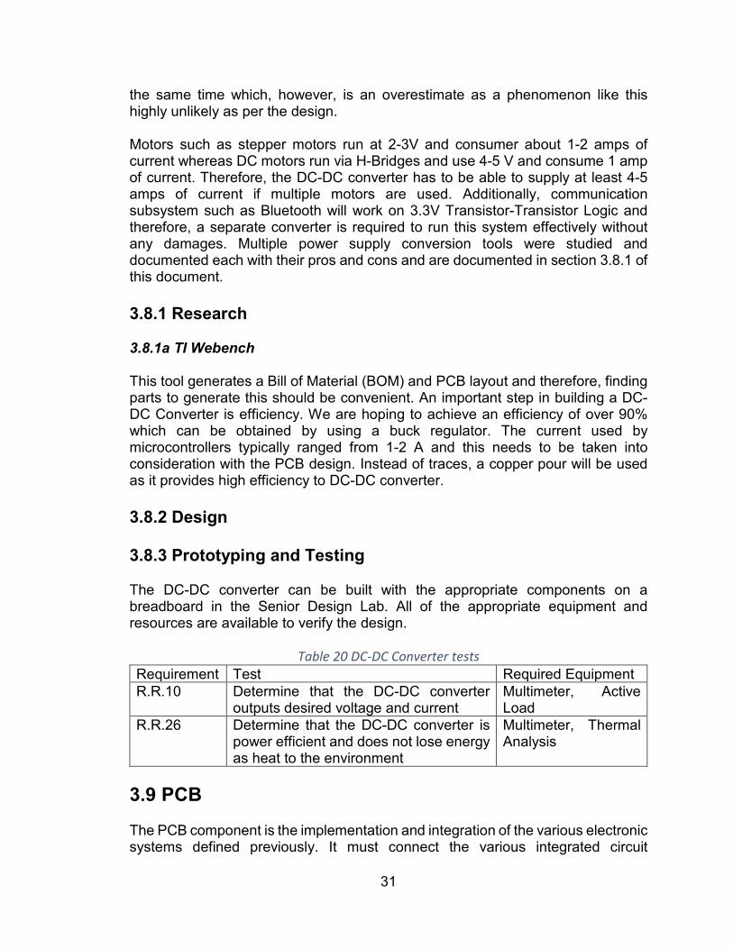
31
the same time which, however, is an overestimate as a phenomenon like this highly unlikely as per the design. Motors such as stepper motors run at 2-3V and consumer about 1-2 amps of current whereas DC motors run via H-Bridges and use 4-5 V and consume 1 amp of current. Therefore, the DC-DC converter has to be able to supply at least 4-5 amps of current if multiple motors are used. Additionally, communication subsystem such as Bluetooth will work on 3.3V Transistor-Transistor Logic and therefore, a separate converter is required to run this system effectively without any damages. Multiple power supply conversion tools were studied and documented each with their pros and cons and are documented in section 3.8.1 of this document. 3.8.1 Research 3.8.1a TI Webench This tool generates a Bill of Material (BOM) and PCB layout and therefore, finding parts to generate this should be convenient. An important step in building a DC-DC Converter is efficiency. We are hoping to achieve an efficiency of over 90% which can be obtained by using a buck regulator. The current used by microcontrollers typically ranged from 1-2 A and this needs to be taken into consideration with the PCB design. Instead of traces, a copper pour will be used as it provides high efficiency to DC-DC converter. 3.8.2 Design 3.8.3 Prototyping and Testing The DC-DC converter can be built with the appropriate components on a breadboard in the Senior Design Lab. All of the appropriate equipment and resources are available to verify the design.
Table 20 DC-DC Converter tests Requirement Test Required Equipment R.R.10 Determine that the DC-DC converter
outputs desired voltage and current Multimeter, Active Load
R.R.26 Determine that the DC-DC converter is power efficient and does not lose energy as heat to the environment
Multimeter, Thermal Analysis
3.9 PCB The PCB component is the implementation and integration of the various electronic systems defined previously. It must connect the various integrated circuit

32
components to the microcontroller and have slots for the peripherals to plug into. The Printed Circuit Board is required to simplify the design of the robot. The electronics that make up the robot consists of 6 motors, a microcontroller, a DC-DC Converter, Motor Drivers, H-Bridge Circuit, encoders, and communication system such as Bluetooth. The PCB connects all these systems together and gives the robot a sophisticated appeal. The PCB needs to be small enough to fit the robot and keep the costs as minimum. The Printer Circuit Board is a 2-layer copper board with silk screen and soldering pads on it. It consists terminal blocks that intake power from the battery and then direct them to a voltage regulator by the means of traces. The width of the traces depends on the power it is carrying. The width of the trace carrying battery power will be thicker than the trace carrying the power to the microcontroller. The PCB contains test points to check voltage and currents at certain spots. Additionally, adding test points helps in determining the signals using an oscilloscope which can help in debugging communication protocol problems that might arise while implementing I2C, SPI, or UART. The PCB also contains a reverse voltage protection circuit leaving the user with minimal adjustments and focus on playing the game out of the box. 3.9.1 Research 3.9.1a Autodesk Eagle CAD 3.9.1b Diptrace 3.9.1c AutoCAD Electrical 3.9.2 Design
Table 21 I/O Schedule Type Connected
Devices Pin Type
Power Requirements
Drive Front Left DC Motor L298 0 PWM, 2 Digital
Drive Front Right DC Motor L298 0 PWM, 2 Digital
Drive Back Left DC Motor L298 1 PWM, 2 Digital
Drive Back Right DC Motor L298 1 PWM, 2 Digital
Intake DC Motor L298 2 PWM, 2 Digital
Launcher Force Stepper L298 3 4x Digital

33
Launcher Release Servo PWM Generator
1 PWM
Feedback Front Left Encoder I/O Expander 2 Digital Feedback Front Right
Encoder I/O Expander 2 Digital
Feedback Back Left Encoder I/O Expander 2 Digital Feedback Back Right
Encoder I/O Expander 2 Digital
Launcher stop Front Limit Switch Microcontroller 1 Digital Launcher stop Back Limit Switch Microcontroller 1 Digital Release stop Limit Switch Microcontroller 1 Digital PWM Generator PCA9685 Microcontroller I2C I/O Expander MCP23017 Microcontroller I2C Bluetooth HC-06 Microcontroller Tx, Rx
3.9.3 Prototyping and Testing The PCB is to be designed and purchased through JLCPCB which sells 2 Layer PCB for $2 for 5 boards. Additionally, the stencils can be purchased for the board at just $6. The stencil is utilized in conjunction with the board and solder paste to quickly and accurately build the PCB. A heating chamber is required to evenly heat the board to prevent damage.
Table 22 Robot PCB Tests Requirement Test Required Equipment C.R.2 Determine that the PCB is an
appropriate size to fit the robot Ruler
R.R.15 R.R.26
Determine that the PCB does not have any shorts or opens
Multimeter
3.10 Software The software component drives the hardware components in the PCB. This includes any control software such as various PID control, state machines, and Bluetooth communication. The software for the Robot must be at least Soft-Real time to ensure that inputs and outputs are processed in a context that does not affect the fidelity of the system. For example, an input from the motor encoders should be processed and utilized in outputs for the relevant motor within a single deterministic loop. If the motors outputs are updated too long from the motor encoder input, the data is no longer valid and could be harmful to the system. Thus, a firm data flow structure must be followed for the entire software system. Additional limitations on the software are based on the microcontroller chosen in section 3.5 Microcontroller. Ideally, the written software follows a strict architecture to enhance readability and debuggability. Debugging is critical for the robot because there are several factors that could lead to failure: Mechanical, Electrical,
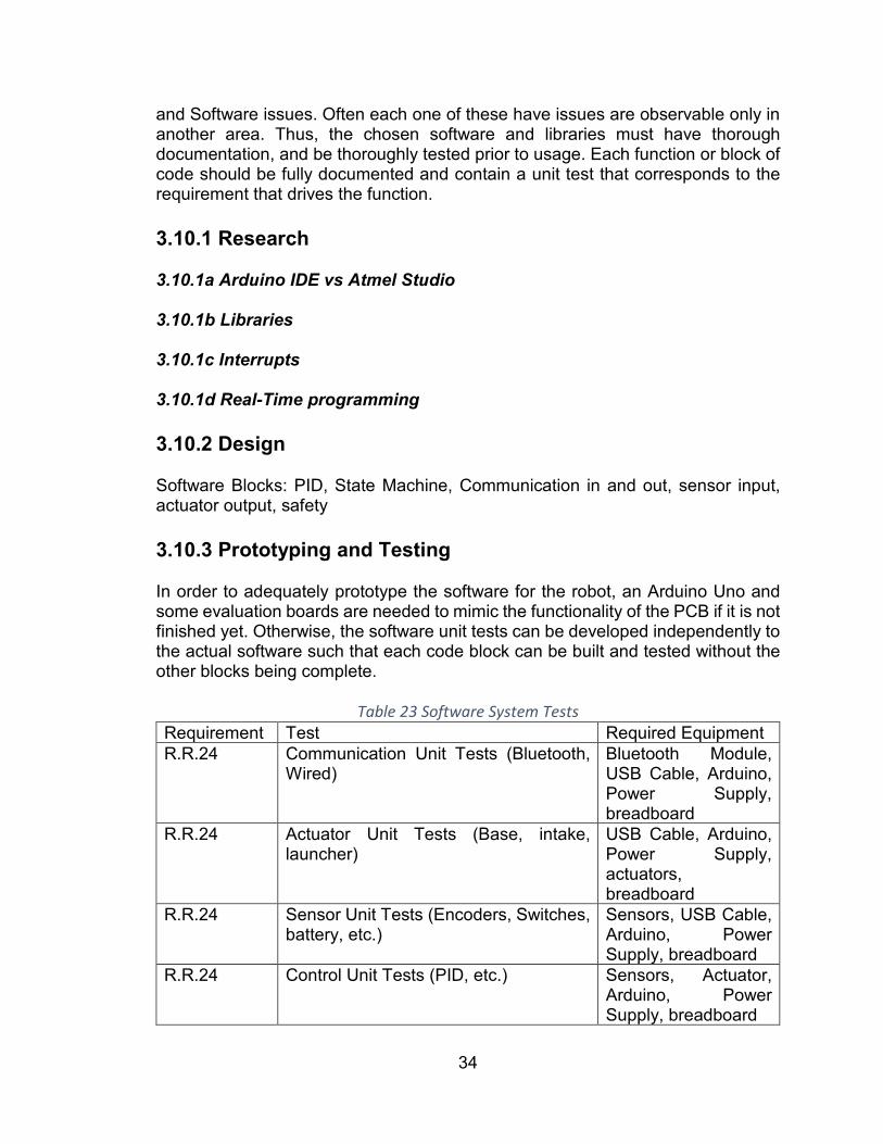
34
and Software issues. Often each one of these have issues are observable only in another area. Thus, the chosen software and libraries must have thorough documentation, and be thoroughly tested prior to usage. Each function or block of code should be fully documented and contain a unit test that corresponds to the requirement that drives the function. 3.10.1 Research 3.10.1a Arduino IDE vs Atmel Studio 3.10.1b Libraries 3.10.1c Interrupts 3.10.1d Real-Time programming 3.10.2 Design Software Blocks: PID, State Machine, Communication in and out, sensor input, actuator output, safety 3.10.3 Prototyping and Testing In order to adequately prototype the software for the robot, an Arduino Uno and some evaluation boards are needed to mimic the functionality of the PCB if it is not finished yet. Otherwise, the software unit tests can be developed independently to the actual software such that each code block can be built and tested without the other blocks being complete.
Table 23 Software System Tests Requirement Test Required Equipment R.R.24 Communication Unit Tests (Bluetooth,
Wired) Bluetooth Module, USB Cable, Arduino, Power Supply, breadboard
R.R.24 Actuator Unit Tests (Base, intake, launcher)
USB Cable, Arduino, Power Supply, actuators, breadboard
R.R.24 Sensor Unit Tests (Encoders, Switches, battery, etc.)
Sensors, USB Cable, Arduino, Power Supply, breadboard
R.R.24 Control Unit Tests (PID, etc.) Sensors, Actuator, Arduino, Power Supply, breadboard

35
R.R.24 Safety system Unit Tests (Heartbeat, etc.)
Arduino, Power supply
R.R.24 Full software tests (Operations at max capacity, timing, etc.)
R.R.24 State machine Unit Tests (including operating modes)
Arduino, Power supply
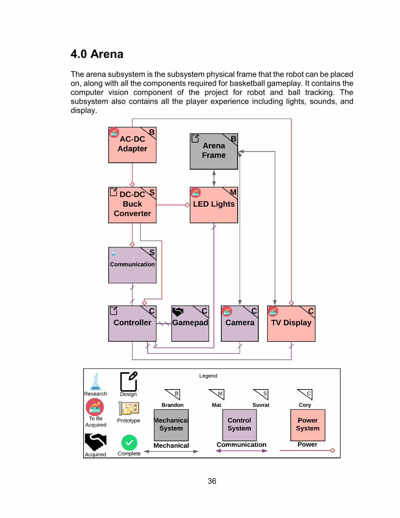
36
4.0 Arena The arena subsystem is the subsystem physical frame that the robot can be placed on, along with all the components required for basketball gameplay. It contains the computer vision component of the project for robot and ball tracking. The subsystem also contains all the player experience including lights, sounds, and display.
37
Figure 12 Arena Subsystem Power and Signal Diagram 4.1 Frame The frame component is the structure to hold the robots, electronics, court, and other components physically. The frame can be quite large; thus, it is designed modularly such that it can be stored and transported in a small location. The court must be perfectly level to ensure the ball remains in place, thus the frame that supports the court flooring must include a leveling apparatus. The exterior of the frame will be closed off to prevent the ball from flying outside of the arena. The material must be transparent to make sure that spectators can see the entire field. 4.1.1 Research 4.1.1a PVC PVC pipe is a light weight and low to medium cost material. The cost will depend on how many connectors are used as they are the most expensive PVC part to buy. The number of connectors used will depend on how much a PVC pipe can maintain level at varying lengths, if the PVC needs to be strengthened more to keep it level that increases cost. However, to alleviate the need for extra connectors we could use thicker pipe, again though the thicker the pipe the more cost increases. PVC pipe is a very portable material though since it does not need any hardware or glue to hold it together. The downside to this portability is that when taken apart and put together repeatedly, it could go together at a different depth than it did before depending on the force applied by the person putting the pieces together. This varying depth can throw off calculations if the arena ends up being off level. A unique problem to PVC is that it is the only round material considered, a round material is not easy to mount other parts on and supplies little support to the flooring of the arena. Additionally, the round property of PVC means that when together it can rotate in place, this can again affect calculations if the camera mount is not placed in the exact same height and position every time. Lastly PVC pipe placed into connectors will always have a lip between the connection point. Because of this lip a piece of plywood may need to be added to the frame in order to ensure the flooring can sit above the lip to make it level. 4.1.1b Metal 4.1.1c Wood 4.1.2 Design The proposed size of the arena is approximately 4 ft width by 5 ft length by 3 ft height which is not to an exact scale of a real court. After creating prototypes of the arena in SolidWorks using the previously mentioned materials and putting

38
together a parts list including price for each, our team decided to use wood because its inexpensive, requires little hardware, and can be easily disassembled and reassembled. The design of the frame will use four 2x4 kiln-dried heat-treated spruce-pine-fir wooden pieces as the walls and base frame. Two pieces on each basket side will serve as the main notched pieces that will hold the middle supporting braces. Each of these two pieces will be cut to four feet in length with 1x1 inch notches cut two inches deep a half inch away from either side of the 2x4. These notches will be used to slot the lengthwise 2x4s into place. The lengthwise 2x4s will have the matching joint cut so that it fits tightly into the basket side notches and is level on the top and bottom of the joining pieces. With these four sides fit tightly together the inner perimeter of the frame should measure 18 feet or 4x4x5x5 feet on each side. Additional 2x1 inch notches shall be cut into the basket-side pieces two inches deep. These notches will be used to hold the supporting braces. The supporting braces will be made of the same type of wood cut to a 2x2 inch plank five feet two inches long. Each side of the supporting braces will have a joint cut to match the notch on the basket-side pieces. This cut should place the supporting braces one inch below the top of the frame. A cross support shall also be placed in a notch cut three inches deep in the middle of the long-side wall. With all walls and supports in place this should create a level platform in which to place the flooring of the arena. The frame will then have lead screws attached to each corner area to keep it level on any surface. Small levels will then be attached to each side to ensure the arena is always level. Figure 13 shows the design of the arena frame and walls.
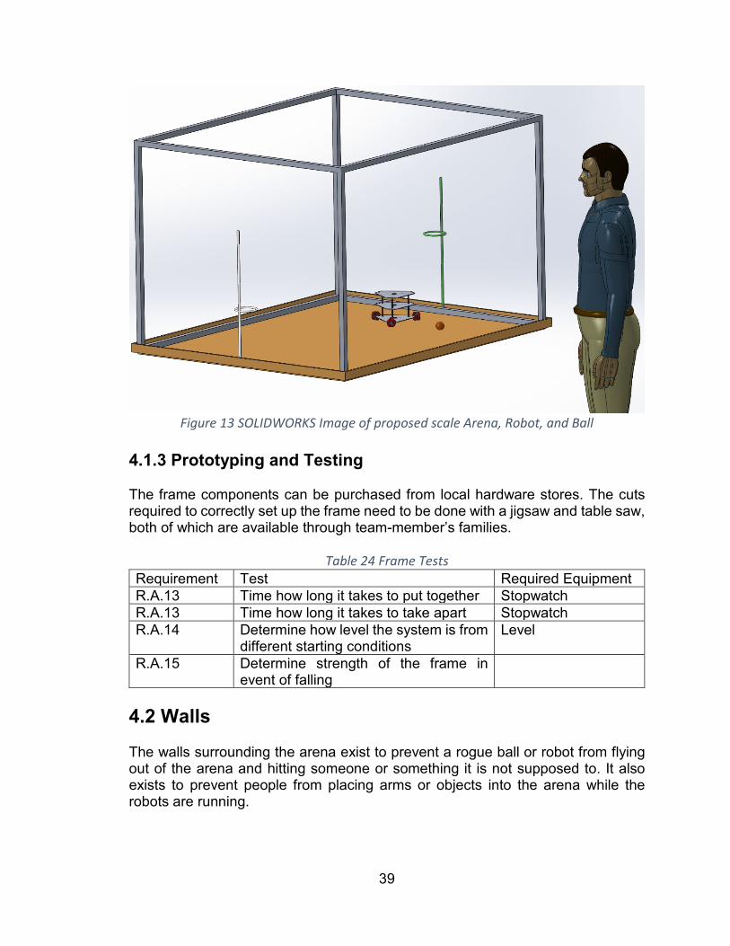
39
Figure 13 SOLIDWORKS Image of proposed scale Arena, Robot, and Ball
4.1.3 Prototyping and Testing The frame components can be purchased from local hardware stores. The cuts required to correctly set up the frame need to be done with a jigsaw and table saw, both of which are available through team-member’s families.
Table 24 Frame Tests Requirement Test Required Equipment R.A.13 Time how long it takes to put together Stopwatch R.A.13 Time how long it takes to take apart Stopwatch R.A.14 Determine how level the system is from
different starting conditions Level
R.A.15 Determine strength of the frame in event of falling
4.2 Walls The walls surrounding the arena exist to prevent a rogue ball or robot from flying out of the arena and hitting someone or something it is not supposed to. It also exists to prevent people from placing arms or objects into the arena while the robots are running.

40
4.2.1 Research 4.2.1a Clear Acrylic Plastic The first material to be researched was clear acrylic plastic. This material is very rigid and the strongest material to be considered. This rigidity would make acrylic the best material for a camera mount alleviating the need for extra mounting material should the camera instead need to be mounted to the frame. The solid acrylic panels would also be an excellent choice for dampening any wind that could occur from outside forces and affect the calculations for shooting the ball, which would be necessary should this project need to be demonstrated in an outdoor environment. A clear acrylic wall would also make the best choice for viewing the robot, making it very easy for any player to see and control their robot. Attaching the wall to the arena is also made easier by the acrylics rigidity as hinges would be all that is needed to hold the walls and would make them collapsible for portability. The downside of the acrylic material is that it is much heavier and would add a tremendous amount of weight to the arena decreasing portability. In addition, the cost of clear acrylic plastic is tremendously more than any other material considered. In fact, this material is the absolute best choice considering all aspects, however the cost is so prohibitive that our team is unable to purchase the necessary quantity needed for this project. 4.2.1b Clear Vinyl Plastic A clear vinyl material is a medium cost solid, but not rigid material. For this project at least six gauge or thicker vinyl would be used. This thickness would allow for hardware to be installed without ripping the vinyl material when it is pulled tightly. The vinyl will need to be pulled as tight as possible in order to make the material as clear as possible and help the ball bounce back into the court and keep the robot from falling out of the court. A vinyl material will also dampen wind almost as good as the rigid acrylic plastic if pulled tight enough. Due to the vinyl not being rigid the camera will have to be mounted on the frame, requiring more hardware. This is a lightweight material and will add almost no weight to the arena making it more portable. In addition, since the material is not rigid it can also be rolled up and carried separately. Attaching vinyl to the arena would entail the use of posts on each corner of the frame, again requiring additional materials. 4.2.1c Mesh The third material considered is a mesh material, either plastic or nylon woven in a net like structure with one inch or less square holes. The mesh material will be the absolute cheapest material considered, costing only several dollars for many square feet of mesh. Mesh is also not a rigid material and thus will not be suitable for attaching the camera boom and so additional hardware will be required. Mesh is however extremely lightweight making it a very good material when considering portability. The ability of mesh to dampen wind is almost nonexistent, so there

41
would require more work in the ball shooting algorithm to insure target goal probability. Mesh will also require additional materials to attach to the frame in the form of posts. These posts could be PVC or another sturdy low-cost material. PVC would be an easy solution as it is sturdy in short lengths and can easily be slotted into the arena by attaching PVC caps to each corner and placing the three-foot PVC pipe with mesh material attached into these caps. 4.2.2 Design 4.2.3 Prototyping and Testing
Table 25 Wall testing Requirement Test Required Equipment R.A.30 Test if the ball goes through the mesh
thrown at different starting speeds and locations
Ball
R.A.16 Test if the ball can roll underneath the wall
Ball
R.A.16 Test if the robot can push through the wall siding
Robot
4.3 Court The court component involves the actual floor of the arena that the robots drive around on. The flooring must be easily transportable and must be able to attach to the frame described in section 4.1 Frame. The floor paneling must lay flat on the frame and contain any required basketball court markings. This is because the ball will move roll around without input force and end up in a hotspot on the court. Additionally, the basketball court markings can be used as a way to ensure the court is placed together properly such that computer vision remains consistent between teardowns. The floor material should have a coefficient of friction high enough that the robot can consistently traverse the court without fear of slipping in the driven directions. If the wheels cannot grip properly on the court, the robot will not move, or the holonomic motions will be very inconsistent, leading to a poor player experience. The court is intended to mimic a full-size basketball court, however, after testing and prototyping, it may be advantageous to switch to a half-court style arena rather than a full-court arena. 4.3.1 Research 4.3.1a Laminate 4.3.1b Metal

42
4.3.1c Particle Board 4.3.2 Design 4.3.3 Prototyping and Testing
Table 26 Court Testing Requirement Test Required Equipment R.A.14 Determine how level the flooring is in
different conditions Level
R.A.17 Determine if the court markings go back into the same place each time
Camera
R.R.13 Determine if the wheels slip on the floor Wheel R.A.14 Determine if the court lays flat inside of
the frame Level
R.A.16 Determine if the chosen wheel can roll over the frame wall
Wheel
4.4 Ball The ball for this project represents a full-size basketball. However, it is much smaller scale and must be throwable by a small-size robot. The ball should not be heavily affected by aerodynamic forces to ensure repeatability. That is, the ball should not be so light that a small gust of wind would affect its motion. Aerodynamic drag is expected and will likely be utilized to gain lift based on the amount of spin on the ball. It should also bounce on the court but not all over the arena from a single throw. This is to prevent the ball from being too difficult to pick up and to prevent the ball from landing on a portion of the robot that it gets stuck on. The ball should be nearly spherical so that it has consistent rolling and launching. It cannot be deformable to the point that a force on the ball causes a permanent dent. 4.4.1 Research 4.4.1a Ping Pong Ball Ping pong balls are 40mm in diameter and weigh about 2.7 grams. They are made from a thin plastic shell that is made of a material to meet a required bounce standard. The standard states that the ball should bounce “25 cm when dropped from 30.5cm.” This bounce is very significant and could lead to significant issues with the robot collecting the ball. However, the ball is very light and could be launched very easily. 4.4.1b Small Tennis Ball

43
A typical tennis ball is a bit too large for the scale of the robot. However, there are much smaller-scale tennis balls that exist for pets. This introduces a small difficulty as there are not standards related to the size and material. Thus, additional research must be conducted after the ball is picked and purchased because the material properties could differ from the documentation provided. The typical size for these tennis balls are about 1.5” in diameter, a perfect size for the scale of the robot. Virtually any tennis ball of this size can be utilized, and there are hundreds of options that are offered in a variety of colors, themes, and prices. 4.4.2 Design The small Tennis ball is chosen for this project. It is a small ball that has some weight and grip on it, and it has a fair amount of grippy material covering the rubber ball. The tennis ball chosen comes in a sports pack from PetSmart that contains one basketball themed ball. This provides a color with sharp contrast to the court so that it can be tracked more easily by the computer vision software. Additionally, it fits the theming of the game.
Figure 14 KONG basketball tennis ball chosen for this project from Amazon
4.4.3 Prototyping and Testing
Table 27 Ball Tests Requirement Test Required Equipment R.A.3 Verify Ball size Calipers R.A.18 Verify ball weight Scale R.A.19 Test throw with different conditions
including outside, inside, with different spins
Tape measure
4.5 Hoop

44
There are two basketball hoops located on either short side of the arena. The hoop is mounted and is set to a diameter that is feasible for the launcher to remain accurate under all conditions. Two hoops are chosen in order to maintain the traditional basketball feel. If two hoops are too many, it is easy to reduce back down to just one hoop in a half-court setting. Each time a basket is made, the score for the game must be updated, thus the hoop must sense when a ball makes it all the way through. It is possible that the ball goes halfway in and pops out, so the sensor must be designed such that it is resilient to false positives (I.E debouncing). The hoop structure should maintain the appearance of a basketball hoop including a backboard, a rim, and a net. Each of the pieces must remain sturdy when the ball inevitably misses and hits the structure. It should be designed in such a way that improves accuracy. The hoop size can increase or decrease based on robot performance, and the backboard should be angled in such a way that increases accuracy. 4.5.1 Research 4.5.1a 3D Print 4.5.2b Metal 4.5.1c Infrared Gate 4.5.1d Ultrasonic 4.5.1e Limit Switch 4.5.2 Design 4.5.3 Prototyping and Testing
Table 28 Hoop Tests Requirement Test Required Equipment R.A.20 Test if the hoop is mounted securely
and can take X force Frame, Weight, Ball
R.A.21 Test if the ball can fall through the hoop Ball R.A.22 Test the sensors and verify accuracy Ball R.A.13 Test if the hoop is put into the same
place each time the court is put together
Frame
4.6 Display and Sounds The arena contains a visual display unit, like a TV, a monitor, or a tablet, that is used to relay information to the players. The display unit needs to be capable of

45
clearly showing the settings page for the game, like a dashboard on a video game console. This page will be used to set up new player robots, game mode, playback options, the score of the game, the current period out of four total periods, the remaining time for the current period, and to adjust the sounds for the game. The display unit will also display the live action 2D top down position on the court in a game engine, this is so the player can glance at important game information on the screen and not lose their place on the court and can continue driving. Showing the live location on the court is also useful for spectators of the game that might not be able to see in the arena. It will also need to be capable of displaying debugging and development information such as the live computer vision feed for any debugging that might need to happen during a game. When searching for a display that will work for these tasks there are some features that will need to be considered. A high definition or super high definition display will be ideal for spectators being able to see the information from a far distance very clearly. For this same reason a larger screen size is also preferred. In addition, only widescreen monitors will be evaluated so when the court, which is a rectangle, and robot location is displayed it can take up the whole screen space instead of making it smaller to fit on a square screen. The higher refresh rate on the display the better so that the game and settings will look smooth. Lower refresh rates might make the picture look choppy which can affect where the player thinks their robot is in respect to the court. Another consideration for choosing displays is how well it can display in daylight conditions. Should the game need to be played outdoors or near a window during daylight hours there may be too much ambient light to see the display. There will be sounds enabled with the game and therefore speakers, either connected to the display or separate entities that will need to be able to supply loud enough sound for both players and spectators to hear. Sound is necessary for this project as it will supply feedback to the user as well as add an emersion element to the game. An additional feature that will be taken into consideration is the ability of the speakers sounds to be mixed with tactile feedback to enable a person who is blind to enjoy the game as well. In this case the speakers would have to produce adequately loud sounds in conjunction with the tactile feedback such as announcing location and orientation on the court. Finally, the price of the display and speakers should be reasonable for a self-funded college group of four to adequately purchase. 4.6.1 Research 4.6.1a Monitor There will be two categories of monitors examined and researched, those with speakers and those with no speakers (sold separately). Regardless of which category is chosen the total price for this section of the arena should be less than 70 USD. The screen of the monitor should be no less than 18”. The display will be

46
showing a live 2D position of the robot on the rectangular court. The monitor will need to display the camera feed for debugging. For these two reasons the display chosen should be widescreen to adequately scale the rectangular arena. Any monitor with built in speakers must have an HDMI or DisplayPort connector to be considered, as these are the two best options for showing HD video and playing sounds through one plug. DisplayPort will be prioritized higher than HDMI for its superior video quality capability. The lowest refresh rate on monitors today is adequate for this project and so will not be a consideration. The weight of the display is taken into consideration as the arena must be portable. Table _______ shows the different monitors for consideration, their size, price, ports, and weight. 4.6.1b Speakers 4.6.2 Design 4.6.3 Prototyping and Testing
Table 29: Display and Sound Test Requirement Test Required Equipment Display Size Measure the screen from the bottom
corner to the top diagonal of the opposite corner.
Tape measure
Widescreen Is the screen size 16:9? Windows Laptop Viewable Outside
View the display outside in a covered area with the correct settings. Stand in the player position and observe if the screen is clearly visible.
Windows Laptop
High Res Use a program and run it on the display to determine the resolution
Windows Laptop
Distance Viewing
Turn on the display to the proper settings. Walk backwards until the display can no longer clearly be seen. Measure this distance to the display.
Windows Laptop
Refresh Rate
Use a program to test the actual refresh rate of the display.
Windows Laptop
Spectators hear sound
Play game sounds at max volume and continue moving backward until the sound can longer clearly be heard. Measure this distance to the arena.
Windows Laptop
4.7 Camera The camera for this project is used for computer vision to track the robots, ball, and goal. It will need to be very accurate to ascertain the exact position of the robot in comparison to the goal so that the robot can make the goal within accuracy
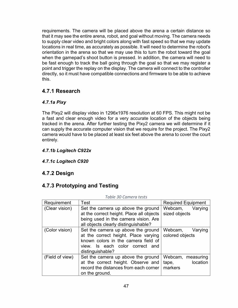
47
requirements. The camera will be placed above the arena a certain distance so that it may see the entire arena, robot, and goal without moving. The camera needs to supply clear video and bright colors along with fast speed so that we may update locations in real time, as accurately as possible. It will need to determine the robot's orientation in the arena so that we may use this to turn the robot toward the goal when the gamepad’s shoot button is pressed. In addition, the camera will need to be fast enough to track the ball going through the goal so that we may register a point and trigger the replay on the display. The camera will connect to the controller directly, so it must have compatible connections and firmware to be able to achieve this. 4.7.1 Research 4.7.1a Pixy The Pixy2 will display video in 1296x1976 resolution at 60 FPS. This might not be a fast and clear enough video for a very accurate location of the objects being tracked in the arena. After further testing the Pixy2 camera we will determine if it can supply the accurate computer vision that we require for the project. The Pixy2 camera would have to be placed at least six feet above the arena to cover the court entirely. 4.7.1b Logitech C922x 4.7.1c Logitech C920 4.7.2 Design 4.7.3 Prototyping and Testing
Table 30 Camera tests Requirement Test Required Equipment (Clear vision) Set the camera up above the ground
at the correct height. Place all objects being used in the camera vision. Are all objects clearly distinguishable?
Webcam, Varying sized objects
(Color vision) Set the camera up above the ground at the correct height. Place varying known colors in the camera field of view. Is each color correct and distinguishable?
Webcam, Varying colored objects
(Field of view) Set the camera up above the ground at the correct height. Observe and record the distances from each corner on the ground.
Webcam, measuring tape, location markers
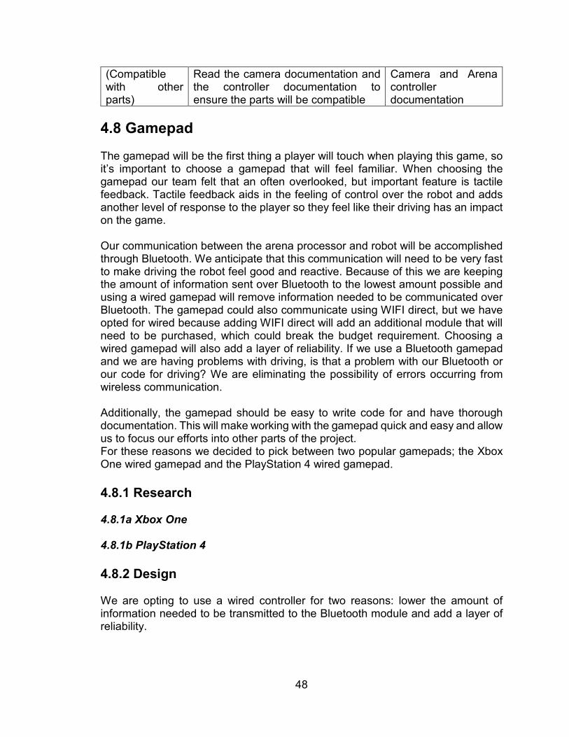
48
(Compatible with other parts)
Read the camera documentation and the controller documentation to ensure the parts will be compatible
Camera and Arena controller documentation
4.8 Gamepad The gamepad will be the first thing a player will touch when playing this game, so it’s important to choose a gamepad that will feel familiar. When choosing the gamepad our team felt that an often overlooked, but important feature is tactile feedback. Tactile feedback aids in the feeling of control over the robot and adds another level of response to the player so they feel like their driving has an impact on the game. Our communication between the arena processor and robot will be accomplished through Bluetooth. We anticipate that this communication will need to be very fast to make driving the robot feel good and reactive. Because of this we are keeping the amount of information sent over Bluetooth to the lowest amount possible and using a wired gamepad will remove information needed to be communicated over Bluetooth. The gamepad could also communicate using WIFI direct, but we have opted for wired because adding WIFI direct will add an additional module that will need to be purchased, which could break the budget requirement. Choosing a wired gamepad will also add a layer of reliability. If we use a Bluetooth gamepad and we are having problems with driving, is that a problem with our Bluetooth or our code for driving? We are eliminating the possibility of errors occurring from wireless communication. Additionally, the gamepad should be easy to write code for and have thorough documentation. This will make working with the gamepad quick and easy and allow us to focus our efforts into other parts of the project. For these reasons we decided to pick between two popular gamepads; the Xbox One wired gamepad and the PlayStation 4 wired gamepad. 4.8.1 Research 4.8.1a Xbox One 4.8.1b PlayStation 4 4.8.2 Design We are opting to use a wired controller for two reasons: lower the amount of information needed to be transmitted to the Bluetooth module and add a layer of reliability.

49
Between the two gamepads we believe the Xbox One gamepad will have the most documentation and support as well as ease of programming and will be using it for our project.
Table 31 Player input functions and gamepad mapping Function Type # Of Axes Forward/Backward + Strafing Joystick 2 Rotation Joystick 1 Shoot Trigger (Analog or Digital) 1 Intake Trigger (Analog or Digital) 1 Select Button 1 Back Button 1
4.8.3 Prototyping and Testing
Table 32 Gamepad tests Requirement Test Required Equipment (Tactile feedback)
Set a function to rumble the gamepad on command. Perform the command and observe the rumbling feeling of the gamepad.
Gamepad, Gamepad software, Arena controller
(Button operation)
Ensure each button performs it’s given task by pressing each button one at a time and observing the buttons output.
Gamepad, Gamepad software, Arena controller
4.9 LED Lights The arena system uses computer vision to detect distance between the robot and the hoop. Based on these distances, the arena converts them into motor velocities for the robot to adjust and shoot the ball. The update rate of the computer vision system is 60Hz and therefore, the arena can perform calculations quickly. However, none of this is possible without proper illumination. This is where the LED lights play an important role. Light Emitting Diode, or LEDs, are a common occurrence in present day. Therefore, due to such high-volume availability they are affordable. Using appropriate current limiting resistors and a microcontroller, one can turn them on or off in a timely fashion. Having a strip of them around the arena will not only illuminate the arena for computer vision, but also make it aesthetically entertaining. There are different colors of LEDs and they can be combined to form different colors by simply mixing their RGB values. Consequently, when the player makes a shot, a sensor will trigger a sequence of LED blinks and create an animation for user entertainment. Each action has an LED sequence preprogrammed into the arena. Making the shot causes the arena to turn green, a Bluetooth connection
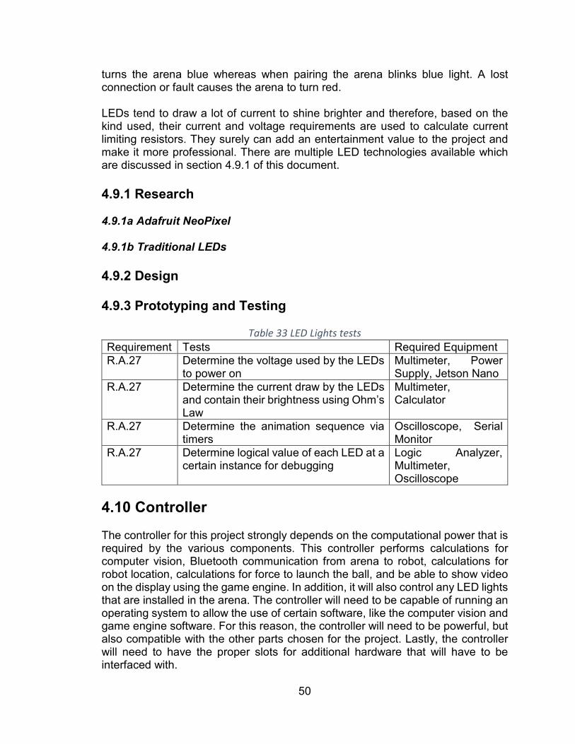
50
turns the arena blue whereas when pairing the arena blinks blue light. A lost connection or fault causes the arena to turn red. LEDs tend to draw a lot of current to shine brighter and therefore, based on the kind used, their current and voltage requirements are used to calculate current limiting resistors. They surely can add an entertainment value to the project and make it more professional. There are multiple LED technologies available which are discussed in section 4.9.1 of this document. 4.9.1 Research 4.9.1a Adafruit NeoPixel 4.9.1b Traditional LEDs 4.9.2 Design 4.9.3 Prototyping and Testing
Table 33 LED Lights tests Requirement Tests Required Equipment R.A.27 Determine the voltage used by the LEDs
to power on Multimeter, Power Supply, Jetson Nano
R.A.27 Determine the current draw by the LEDs and contain their brightness using Ohm’s Law
Multimeter, Calculator
R.A.27 Determine the animation sequence via timers
Oscilloscope, Serial Monitor
R.A.27 Determine logical value of each LED at a certain instance for debugging
Logic Analyzer, Multimeter, Oscilloscope
4.10 Controller The controller for this project strongly depends on the computational power that is required by the various components. This controller performs calculations for computer vision, Bluetooth communication from arena to robot, calculations for robot location, calculations for force to launch the ball, and be able to show video on the display using the game engine. In addition, it will also control any LED lights that are installed in the arena. The controller will need to be capable of running an operating system to allow the use of certain software, like the computer vision and game engine software. For this reason, the controller will need to be powerful, but also compatible with the other parts chosen for the project. Lastly, the controller will need to have the proper slots for additional hardware that will have to be interfaced with.

51
4.10.1 Research 4.10.1a Raspberry Pi 3 Model B+ A Raspberry Pi 3 B+ was originally suggested because of its built-in Bluetooth capability and processing power, however, due to the inclusion of the game engine video display, we believe an onboard GPU will be necessary for smooth video. 4.10.1b Jetson Nano The Jetson Nano does not however include a built in Bluetooth module so that must be purchased. In addition, the Jetson Nano supplies much more processing and computational power than the Raspberry Pi 3 B+ and for this reason a webcam for computer vision with a high frame rate could now be implemented. 4.10.2 Design 4.10.3 Prototyping and Testing
Table 34 Controller tests Requirement Test Required Equipment (Bluetooth Compatible)
Look at the documentation for controller and Bluetooth module.
Part documentation
(Processing Power)
Run game video, Computer vision camera software, LEDs, and Bluetooth module. Observe and record specs using software and visually look for lag in video playback.
Controller Monitoring Software
(Proper slots for parts)
Check that the correct number of slots and slot type is included in the controller.
Controller documentation
(Supplies enough voltage to parts)
Using documentation for the controller check that the supplied voltage is capable of supporting the part that will be plugged in.
Controller documentation
4.11 Communication The communication subsystem allows the Arena to send commands to the robot. To accomplish this, the Arena must have a communication system on board and send data over a wireless link. The communication subsystem needs to have a data update frequency of 30Hz at the minimum. Failure to do so can cause latency in sending commands to the robot and thereby an overall latency in the system’s response. This latency hinders the robot from shooting successfully 75% of the time as per the requirements.
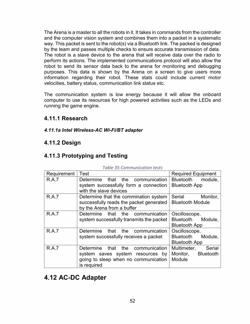
52
The Arena is a master to all the robots in it. It takes in commands from the controller and the computer vision system and combines them into a packet in a systematic way. This packet is sent to the robot(s) via a Bluetooth link. The packed is designed by the team and passes multiple checks to ensure accurate transmission of data. The robot is a slave device to the arena that will receive data over the radio to perform its actions. The implemented communications protocol will also allow the robot to send its sensor data back to the arena for monitoring and debugging purposes. This data is shown by the Arena on a screen to give users more information regarding their robot. These stats could include current motor velocities, battery status, communication link status etc. The communication system is low energy because it will allow the onboard computer to use its resources for high powered activities such as the LEDs and running the game engine. 4.11.1 Research 4.11.1a Intel Wireless-AC Wi-Fi/BT adapter 4.11.2 Design 4.11.3 Prototyping and Testing
Table 35 Communication tests Requirement Test Required Equipment R.A.7 Determine that the communication
system successfully form a connection with the slave devices
Bluetooth module, Bluetooth App
R.A.7 Determine that the commination system successfully reads the packet generated by the Arena from a buffer
Serial Monitor, Bluetooth Module
R.A.7 Determine that the communication system successfully transmits the packet
Oscilloscope, Bluetooth Module, Bluetooth App
R.A.7 Determine that the communication system successfully receives a packet
Oscilloscope, Bluetooth Module, Bluetooth App
R.A.7 Determine that the communication system saves system resources by going to sleep when no communication is required
Multimeter, Serial Monitor, Bluetooth Module
4.12 AC-DC Adapter

53
4.12.1 Description This component is required to convert power from a standard US 120V, 60 Hz outlet to DC power. This component must be highly efficient; thus, it will be purchased. A single outlet is expected to support the entire Arena subsystem including TV display, Controller, and other loads. A household power strip will be attached to the frame to split AC power from the outlet to the TV Display and AC-DC adapter systems. The total power between the two must be calculated to ensure a single outlet is not tripped, however the TV display is separate from the AC-DC adapter power requirements.
Table 36 Power Requirement Calculation Component Average Power Peak Power Jetson Nano 10 W 30 W LEDs Other Electronics Total
1.12.2 Research 4.12.2a LEDMO Switching Converter Power Supply Adapter Transformer 4.12.2b Apple USB Adapter 4.12.3 Design 4.12.4 Prototyping and Testing
Table 37 AC-DC Convertor Tests Requirement Test Required Equipment R.A.10 Test if the AC-DC adapter regulates
voltage at the correct value Voltmeter, active load
R.A.10 Test if the AC-DC adapter can support the required loads value
Voltmeter, active load
R.A.10 Test the AC-DC adapter efficiency Voltmeter, active load R.A.10 Test the AC-DC adapter with the actual
loads
4.13 DC-DC Converter The AC to DC converter converts the 120V at 60Hz to a mere 12V DC signal with 10 amps of output. This is not ideal for the arena systems as it can damage the components due to excessive power. Therefore, this input needs to be further
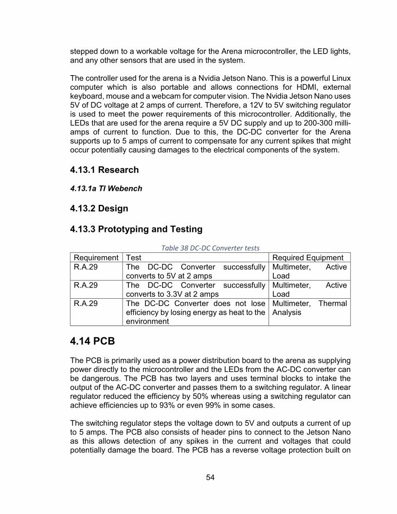
54
stepped down to a workable voltage for the Arena microcontroller, the LED lights, and any other sensors that are used in the system. The controller used for the arena is a Nvidia Jetson Nano. This is a powerful Linux computer which is also portable and allows connections for HDMI, external keyboard, mouse and a webcam for computer vision. The Nvidia Jetson Nano uses 5V of DC voltage at 2 amps of current. Therefore, a 12V to 5V switching regulator is used to meet the power requirements of this microcontroller. Additionally, the LEDs that are used for the arena require a 5V DC supply and up to 200-300 milli-amps of current to function. Due to this, the DC-DC converter for the Arena supports up to 5 amps of current to compensate for any current spikes that might occur potentially causing damages to the electrical components of the system. 4.13.1 Research 4.13.1a TI Webench 4.13.2 Design 4.13.3 Prototyping and Testing
Table 38 DC-DC Converter tests Requirement Test Required Equipment R.A.29 The DC-DC Converter successfully
converts to 5V at 2 amps Multimeter, Active Load
R.A.29 The DC-DC Converter successfully converts to 3.3V at 2 amps
Multimeter, Active Load
R.A.29 The DC-DC Converter does not lose efficiency by losing energy as heat to the environment
Multimeter, Thermal Analysis
4.14 PCB The PCB is primarily used as a power distribution board to the arena as supplying power directly to the microcontroller and the LEDs from the AC-DC converter can be dangerous. The PCB has two layers and uses terminal blocks to intake the output of the AC-DC converter and passes them to a switching regulator. A linear regulator reduced the efficiency by 50% whereas using a switching regulator can achieve efficiencies up to 93% or even 99% in some cases. The switching regulator steps the voltage down to 5V and outputs a current of up to 5 amps. The PCB also consists of header pins to connect to the Jetson Nano as this allows detection of any spikes in the current and voltages that could potentially damage the board. The PCB has a reverse voltage protection built on

55
it to prevent possible damages that could occur due to plugging the power supply in incorrectly. The PCB makes the arena look sophisticated and allows the electronics to be hidden successfully in the arena. There are myriad of software tools that allow successful creating of schematics and PCBs. These technologies are discussed in section 4.14.1 of this document. 4.14.1 Research 4.14.1a Autodesk Eagle CAD 4.14.1b DipTrace 4.14.1c AutoCAD Electrical 4.14.2 Design
Table 39 Arena I/O Schedule Type Connected
Devices Pin Type
Power Requirements
Bluetooth Intel Module Microcontroller Slot LED’s NeoPixel Microcontroller GPIO Display & Sound TV Microcontroller HDMI Gamepad Xbox
controller Microcontroller USB
Gamepad 2 Xbox Controller
Microcontroller USB
Switch Digital Microcontroller GPIO 4.14.3 Prototyping and Testing
Table 40 PCB Tests Requirement Test Required Equipment C.A.4 Determine that the PCB is an
appropriate size to fit the Arena Ruler
C.A.4 Determine that the PCB does not have any shorts or opens
Multimeter
4.15 Computer Vision The computer vision portion is one of the most vital aspects of this project. It will detect and track the location of all moving objects and defining court features. It will be capable of distinguishing between different robots and supply an accurate location to be used in other portions of the project, most notably, shooting the ball.
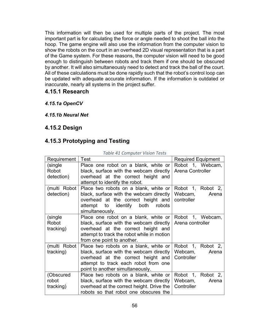
56
This information will then be used for multiple parts of the project. The most important part is for calculating the force or angle needed to shoot the ball into the hoop. The game engine will also use the information from the computer vision to show the robots on the court in an overhead 2D visual representation that is a part of the Game system. For these reasons, the computer vision will need to be good enough to distinguish between robots and track them if one should be obscured by another. It will also simultaneously need to detect and track the ball of the court. All of these calculations must be done rapidly such that the robot’s control loop can be updated with adequate accurate information. If the information is outdated or inaccurate, nearly all systems in the project suffer. 4.15.1 Research 4.15.1a OpenCV 4.15.1b Neural Net 4.15.2 Design 4.15.3 Prototyping and Testing
Table 41 Computer Vision Tests Requirement Test Required Equipment (single Robot detection)
Place one robot on a blank, white or black, surface with the webcam directly overhead at the correct height and attempt to identify the robot.
Robot 1, Webcam, Arena Controller
(multi Robot detection)
Place two robots on a blank, white or black, surface with the webcam directly overhead at the correct height and attempt to identify both robots simultaneously.
Robot 1, Robot 2, Webcam, Arena controller
(single Robot tracking)
Place one robot on a blank, white or black, surface with the webcam directly overhead at the correct height and attempt to track the robot while in motion from one point to another.
Robot 1, Webcam, Arena controller
(multi Robot tracking)
Place two robots on a blank, white or black, surface with the webcam directly overhead at the correct height and attempt to track each robot from one point to another simultaneously.
Robot 1, Robot 2, Webcam, Arena Controller
(Obscured robot tracking)
Place two robots on a blank, white or black, surface with the webcam directly overhead at the correct height. Drive the robots so that robot one obscures the
Robot 1, Robot 2, Webcam, Arena Controller
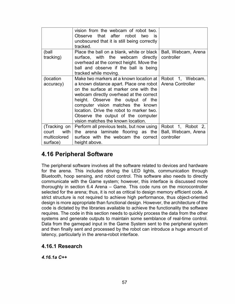
57
vision from the webcam of robot two. Observe that after robot two is unobscured that it is still being correctly tracked.
(ball tracking)
Place the ball on a blank, white or black surface, with the webcam directly overhead at the correct height. Move the ball and observe if the ball is being tracked while moving.
Ball, Webcam, Arena controller
(location accuracy)
Make two markers at a known location at a known distance apart. Place one robot on the surface at marker one with the webcam directly overhead at the correct height. Observe the output of the computer vision matches the known location. Drive the robot to marker two. Observe the output of the computer vision matches the known location.
Robot 1, Webcam, Arena Controller
(Tracking on court with multicolored surface)
Perform all previous tests, but now using the arena laminate flooring as the surface with the webcam the correct height above.
Robot 1, Robot 2, Ball, Webcam, Arena controller
4.16 Peripheral Software The peripheral software involves all the software related to devices and hardware for the arena. This includes driving the LED lights, communication through Bluetooth, hoop sensing, and robot control. This software also needs to directly communicate with the Game system; however, this interface is discussed more thoroughly in section 6.4 Arena – Game. This code runs on the microcontroller selected for the arena; thus, it is not as critical to design memory efficient code. A strict structure is not required to achieve high performance, thus object-oriented design is more appropriate than functional design. However, the architecture of the code is dictated by the libraries available to achieve the functionality the software requires. The code in this section needs to quickly process the data from the other systems and generate outputs to maintain some semblance of real-time control. Data from the gamepad input in the Game System sent to the peripheral system and then finally sent and processed by the robot can introduce a huge amount of latency, particularly in the arena-robot interface. 4.16.1 Research 4.16.1a C++

58
4.16.2 Design 4.16.3 Prototyping and Testing
Table 42 Peripheral Software tests Requirement Test Required Equipment R.A.30 Communication Unit Tests Bluetooth Module,
power supply, Nano R.A.30 LED Unit Tests Nano, Power supply,
LED’s R.A.30 Sensor Unit Tests Nano, Power Supply,
Sensors R.A.30 Full software tests Nano, Power Supply,
terminal monitor 5.0 Game System The Game system harnesses the power of a game engine to deploy commonly used features that are available in a virtual environment. The project requires players to be able to adjust settings, start and stop timers, display scores and other feedback, and assist the user by showing a 2D virtual representation of an environment. The game system is essentially the primary software arm of the Arena system, but it can be developed and act independently from the Arena system. This system is the most feature-scalable system in the project. A large number of extra software functionality can be added to the project through the game system. These things include different robot settings based on a chosen player. This feature could adjust speeds, accuracy, or force limits to vary the player experience. Additional control logic such as autonomy or machine learning could be introduced into the game system to change the player experience quite dramatically.

59
Figure 15 Game system block diagram
5.1 Game Engine The game engine will be responsible for a few tasks overall and will act as a hub for data to flow in and out of. It must be able to handle data visualization such as showing a mockup of where the physical components such as the robot and ball are on the field or playing an animation when a shot is made or missed. Using data sent from the field and robot, the game engine will also handle collision detection and send feedback to the gamepad being used by the player. The game engine will also need to be capable of both 2D and 3D animation to accomplish its tasks. 5.1.1 Research 5.1.1a Unity Unity is useable for both 3D and 2D games and simulation. Most of the group has used Unity before so there is some experience there. A major plus is that the base edition of this engine is free to use. Due to that Unity is under consideration for being used for both the 2D visualization and tracking as well as the animation after a made shot. Unity looks to be a primarily 3D based engine and there seems to be more material for tutorial in 3D rather than the 2D side. A downside of unity is that

60
the UI can get rather cluttered and unusable. It also has a rather steep learning curve if the developer is just learning how to use Unity with C#. On top of that, there are solutions, but no simple answer to doing inter process communication between Unity and other things, such as a C++ program or Python script. 5.1.1b Godot Godot seems to be slightly opposite of Unity in that it looks more 2D friendly than 3D. It comes with a lot of tools to help a first time Godot developer get started creating what they need to. Like Unity, it has its own suite of animation tools for the developer to use instead of using a separate software such as Cinema4D or Maya. As well as supporting C++ and C#, Godot also has its own language, GDScript which is a lightweight Python-like language. Godot in general is a more lightweight program and requires less resources to run. This may prove to be useful as the resources to run the game system through whatever controller is chosen for use may be limited. Godot, like Unity, has an asset hierarchy that dictates how and what items are allowed to interact with. 5.1.2 Design 5.1.3 Prototyping and Testing Prototyping will be done using Godot. The first objective for prototyping the game system will be to create a base scene that takes the shape of a rectangle to act as the arena. On this scene there will be a few shapes that will act as the ball, rim, and robot. After the scene is set up, the first 2 tests from Table 40 below will be able to be tested. The tests will be conducted in the order of the requirements fulfilled as each requirement is a concrete subcategory of the game system. Verifying that the game submodules work effectively together will require the rest of the subsystems work first, therefore it doesn’t explicitly fall under a requirement listed in section 2.5
Table 43 Game engine tests Requirement Test Required Equipment R.G.1 Moving shapes programmatically Laptop R.G.1 Moving shapes via gamepad input Laptop R.G.2 Check data is displayed properly Laptop R.G.3 Check date and time are accurate Laptop Verify game submodules work together
in the intended fashion Laptop
After the tests are validated, the parts will be combined into one scene that contains the visualization for the court, as well as the data display parts and rechecked to make sure the components still function properly. Once that is verified it will be made into the official design.

61
5.2 Collision Detection The game engine system is responsible for protecting the robot in events of poor user input. For example, if the player constantly runs into the wall, the robot would either drive over the wall and flip, or it would burn out the motors and cause electrical or structural damage. Another instance that requires collision detection is when two robots run into each other. Again, these events could cause electrical or structural damage and prevent consistent playing. In both instances, the collision detection should be aware when a robot is entering a zone that could be dangerous and protect the robot. The protections could be reducing motor power, slowing the robot, or preventing input entirely. Another useful feature of collision detection is automatic intaking when the ball is near the front of the robot. This is a player-assist feature that can have adjustable settings. 5.2.1 Research 5.2.1a Game-Engine Collision Detection 5.2.1b Optimization 5.2.1c Collision Response 5.2.2 Design 5.2.3 Prototyping and Testing
Table 44 Collision Detection Tests Requirement Test Required Equipment R.G.8, R.P.4 Verify Safety System Robot, Display,
Frame R.G.6 Verify Collision Avoidance algorithms Robot, Display,
Frame R.G.6 Verify accuracy of simulation versus
physical Robot, Camera, Court. Tape Measure
5.3 Video Playback It is very common to have a replay of events that happened prior to a score in any sport. When a player scores a goal, it would be exciting and useful for spectators to see the motions of the robot and ball in the time leading up to the robot shooting the ball. This requires a storage buffer containing the positional data of the robots and ball, and timing for ball entering the hoop. At the time of scoring, a short playback of the positional data (in 2D) and then a pre-rendered 3D animation of the ball being launched and going into a hoop play. This is very similar to what bowling centers do for different types of pins being knocked down. The pre-
Brandon Gross
Collision game-engine design Collision response state diagram

62
rendered 3D animation reduces complexity of the simulation while still providing the feeling of experiencing the goal again. 5.3.1 Research 5.3.2 Design 5.3.3 Prototyping and Testing Prototyping of the video playback does not require the actual video that will be played to be done in order to be completed. The team can substitute any video to use for testing purposes and just swap it with the correct rendered animation once it is complete. The testing will follow an order outlined below consisting of unit tests that slowly scale up until we get the full project.
Table 45 Video Playback tests Requirement Test Required Equipment R.G.5 Manually trigger any video
Laptop
R.G.5 Make sure our video is rendered properly
Laptop
R.G.5 Manually trigger our rendered video
Laptop
R.G.5 Trigger scene on basket score/non-score
Nano
6.0 Subsystem Integration The system integration section identifies high-risk interfaces that must be carefully designed and tested to avoid problems that occur when multiple systems are designed in parallel. Three robot interfaces are identified, and two major system interfaces are identified. The robot interfaces are high-risk because they are the most likely point of failure in the project, and the entire project depends on the robot’s capabilities to be completed appropriately. Although these components exist within the same subsystem, their critical risk status elevates the importance of integration. The system interfaces are not within the same subsystem; thus their integration is not discussed within their respective system discussions. As such, the interfacing between the major systems is developed in this section. 6.1 Base – Intake The Base-Intake integration is identified as the mounting interface between the base subsystem, and intake subsystem. This interface ensures the compatibility between the intake and the wheel locations, and the existence of mounting
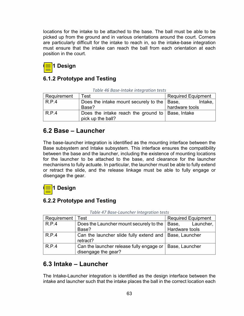
63
locations for the intake to be attached to the base. The ball must be able to be picked up from the ground and in various orientations around the court. Corners are particularly difficult for the intake to reach in, so the intake-base integration must ensure that the intake can reach the ball from each orientation at each position in the court. 6.1.1 Design 6.1.2 Prototype and Testing
Table 46 Base-Intake integration tests Requirement Test Required Equipment R.P.4 Does the intake mount securely to the
Base? Base, Intake, hardware tools
R.P.4 Does the intake reach the ground to pick up the ball?
Base, Intake
6.2 Base – Launcher The base-launcher integration is identified as the mounting interface between the Base subsystem and Intake subsystem. This interface ensures the compatibility between the base and the launcher, including the existence of mounting locations for the launcher to be attached to the base, and clearance for the launcher mechanisms to fully actuate. In particular, the launcher must be able to fully extend or retract the slide, and the release linkage must be able to fully engage or disengage the gear. 6.2.1 Design 6.2.2 Prototype and Testing
Table 47 Base-Launcher Integration tests Requirement Test Required Equipment R.P.4 Does the Launcher mount securely to the
Base? Base, Launcher, Hardware tools
R.P.4 Can the launcher slide fully extend and retract?
Base, Launcher
R.P.4 Can the launcher release fully engage or disengage the gear?
Base, Launcher
6.3 Intake – Launcher The Intake-Launcher integration is identified as the design interface between the intake and launcher such that the intake places the ball in the correct location each
Brandon Gross
Mounting holes for the base and intake, or a plate / otherwise.
Brandon Gross
Mounting holes for the launcher and servo mechanism. Clearance spots for the mechanisms.

64
time for the launcher to hit consistently. Further, the intake must not interfere with the launching mechanism; in particular, the launching mechanism must be able to fully extend or retract regardless of the location or orientation of the intake. 6.3.1 Design 6.3.2 Prototype and Testing
Table 48 Intake-Launcher Integration Tests Requirement Test Required Equipment R.P.4 Does the intake place the ball into the
correct location for the launcher? Intake, Launcher, Power Supply
R.P.4 Can the launcher shoot without interference from the intake at any rotation?
Intake, Launcher
6.4 Arena – Game The Arena-Game integration involves interfacing between the Arena system and the game system. The game system requires position data of the robots and the ball from the camera stationed above the arena to accurately update the locations of the simulated versions in the game engine. Additionally, the game system must send the gamepad data to the arena system to process the player input’s and send them out to the robots. 6.4.1 Design Inter-process communication can be accomplished in a variety of ways between scripts and programs of different languages. The two options the team were most comfortable with were TCP/IP sockets and shared memory. Shared memory is much easier with a C++ or Python based environment while TCP/IP sockets would be better for use with something like C# and Unity. 6.4.2 Prototyping and Testing The Arena-Game interface prototype simply requires the Arena and game systems to be completed. Once the systems are completed, a single software section must be built and tested to interface the Arena and Game software systems.
Table 49 Arena-Game Integration Tests Requirement Test Required Equipment R.P.4 Send and verify signals between arena
and game N/A
R.P.4 Check visualization matches data sent from the arena
N/A
Brandon Gross
The ball-holder section
Brandon Gross
Inter-process communication between arena-specific nodes and game-specific nodes.

65
6.5 Robot - Arena The Robot-Arena integration is identified as the interface between the components of the Robot and Arena. For example, the ball must interface correctly with the Intake subsystem, and launch subsystem. The fiducials for computer vision to track on the robot are designed in this section. The robot and arena share information via Bluetooth. Arena uses camera information and controller inputs, combines them into a packet and sends it to a buffer. The Bluetooth system reads the buffer periodically and sends the commands to the robot. The robot then parses the packet into useful information and carries out the commanded tasks. 6.5.1 Design 6.5.2 Prototype and Testing
Table 50 Robot-Arena Integration Tests Requirement Test Required Equipment R.R.2 R.A.2 R.P.4
The robot and arena can communicate bidirectionally
Robot, Arena, Terminal
R.A.24 R.A.30 R.P.4
The arena can control the robot Robot, Arena, Terminal
R.A.12 R.P.4
The computer vision system can track the robot’s position
Robot, Arena, Terminal, Display
7.0 Administrative Overhead is required as project size increases. The overhead involved for this project relates to task management, scheduling, budgeting, and communication. Each of these is necessary to achieve the requirements set forth by the team. 7.1 Budget and Bill of Materials
Table 51 Robot Budget Item Price (USD) Quantity Subtotal (USD) Launching Hardware $ 20.00 1 $20.00 Drive Hardware $ 30.00 1 $30.00 Intake Hardware $ 20.00 1 $20.00 Intake Motor $ 15.00 1 $ 5.00 Drive Motor $ 20.00 3 $60.00
Brandon Gross
Bluetooth packet design (Discussed above?) and interaction between the data stored on the Nano and data stored on the Arduino.
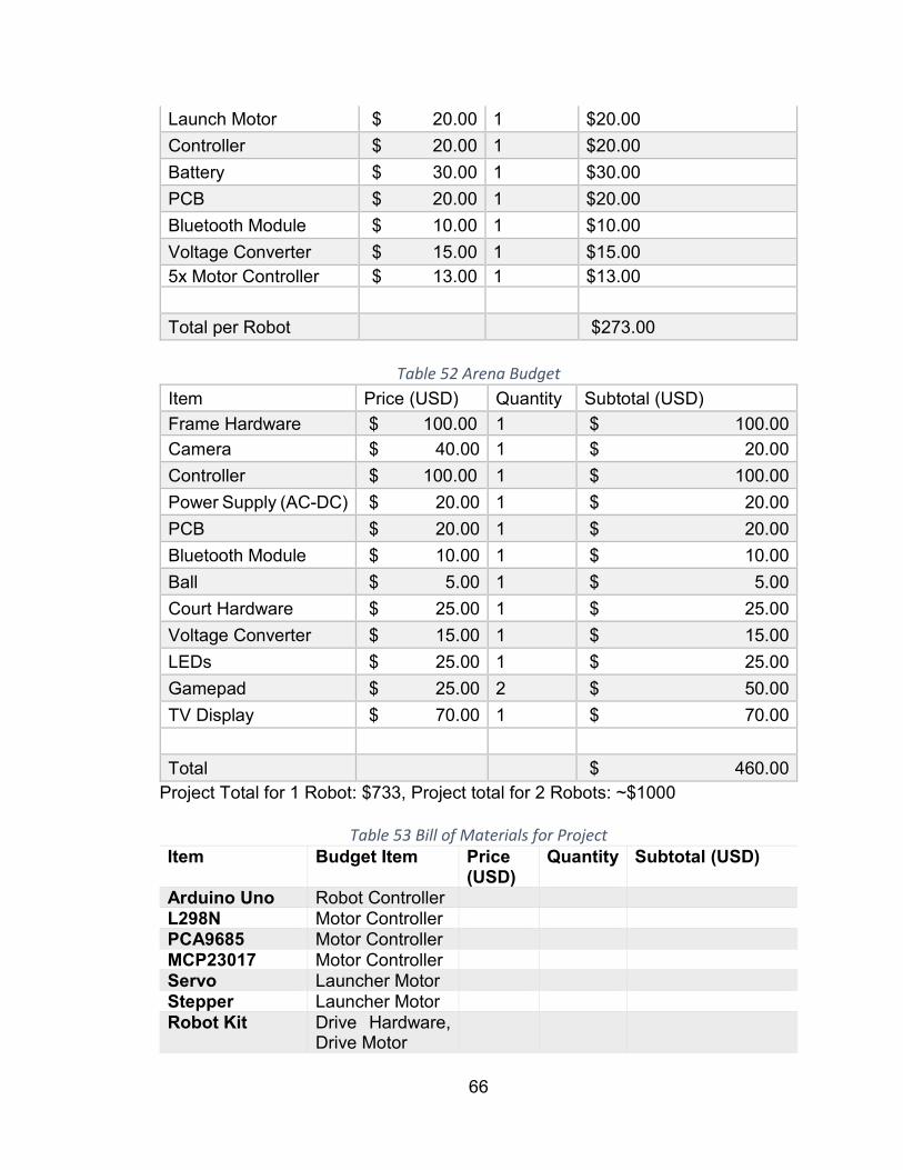
66
Launch Motor $ 20.00 1 $20.00 Controller $ 20.00 1 $20.00 Battery $ 30.00 1 $30.00 PCB $ 20.00 1 $20.00 Bluetooth Module $ 10.00 1 $10.00 Voltage Converter $ 15.00 1 $15.00 5x Motor Controller $ 13.00 1 $13.00 Total per Robot $273.00
Table 52 Arena Budget
Item Price (USD) Quantity Subtotal (USD) Frame Hardware $ 100.00 1 $ 100.00 Camera $ 40.00 1 $ 20.00 Controller $ 100.00 1 $ 100.00 Power Supply (AC-DC) $ 20.00 1 $ 20.00 PCB $ 20.00 1 $ 20.00 Bluetooth Module $ 10.00 1 $ 10.00 Ball $ 5.00 1 $ 5.00 Court Hardware $ 25.00 1 $ 25.00 Voltage Converter $ 15.00 1 $ 15.00 LEDs $ 25.00 1 $ 25.00 Gamepad $ 25.00 2 $ 50.00 TV Display $ 70.00 1 $ 70.00 Total $ 460.00
Project Total for 1 Robot: $733, Project total for 2 Robots: ~$1000
Table 53 Bill of Materials for Project Item Budget Item Price
(USD) Quantity Subtotal (USD)
Arduino Uno Robot Controller L298N Motor Controller PCA9685 Motor Controller MCP23017 Motor Controller Servo Launcher Motor Stepper Launcher Motor Robot Kit Drive Hardware,
Drive Motor

67
DC-DC Convertor
Voltage Converter
Bluetooth module
Bluetooth Module (Robot)
Intel Module Bluetooth Module (Arena)
Level Shifter PCB Jetson Nano Arena Controller SD Card Arena Controller DC Power Supply
Power Supply (AC)
SD Card Reader
Arena Controller
DC Power supply 2
Power Supply (AC)
Arena hardware
Frame Hardware
Frame Material Frame Hardware
Table 54 Bill of Materials for Manufacturing and Reproducing Item Budget Item Price
(USD) Quantity Subtotal (USD)
L298N Motor Controller PCA9685 Motor Controller MCP23017 Motor Controller Servo Launcher Motor Stepper Launcher Motor Robot Kit Drive Hardware,
Drive Motor 1.25
SD Card Arena Controller PCB PCB Jetson Nano Arena Controller Bluetooth module
Communication
7.2 Milestones Figure 16 is a Gantt chart that shows the various major milestones and project timelines required to successfully complete the project in Senior Design 1 and Senior Design 2 courses. The major critical path is that of the PCB design, purchase, and fabrication due to the long lead time to purchase and build the PCBs.

68
Figure 16 Gantt Chart indicating critical milestones and work timelines
7.3 Communication Communication is critical to the project team’s success. A thorough use of documentation and sharing tools allows the team to work at peak efficiency regardless of physical location or project timeline. Although there are many tools
69
available to achieve this, three critical tools that can seamlessly link together are utilized to reduce the number of sites or applications to download. 7.3.1 Microsoft SharePoint SharePoint and other Microsoft products are used for this project because it can act as a one-stop shop where all the materials required for the project can be found. SharePoint itself is a website platform that has various pages and plugins. Each research topic has its own page that the team fills out as the research and design is completed. This allows all our research to be compiled real time and is organized such that information can be retrieved when necessary. The plugins utilized within SharePoint include Microsoft Planner, a tool that allows users to add tasks with information like assignee, due date, and relevant files. The tasks are tracked as cards that can be moved around with order of importance, or have reminders set so that things are finished on time. Everything with the SharePoint is synced and stored on OneDrive, Microsoft’s cloud storage platform. This allows for version control of all the documentation required for the project. 7.3.2 Discord Discord is a free VoIP software that provides chat, screen-sharing, file-sharing, voice and video calls in an easy to use platform. Discord is chosen over Slack, Skype, and other chat software because it provides the required features for free, it is stable, and the team has utilized it for other projects in the past. This tool provides us a way to store any text messaging between members of the group and return to it at any point in the future. 7.3.3 GitHub GitHub is a cloud application that integrates with the git version control scheme. The team can work on their local machine and develop any files or software required, and then when finished, upload the file to the cloud that other members can update from. The tool is very powerful when simultaneously working on the same file because git can merge different versions of the file based on changes made. This is particularly helpful in software that are modularized into functions or blocks that multiple members can work on simultaneously without losing progress in another block. 8.0 Project Summary and Conclusion 9.0 Appendices 9.1 Copyright Permissions

70
9.2 Data Sheets