Robert's Rocket Project -...
28
Robert's Rocket Project Space Access '15 Conference April 30, 2015 www.watzlavick.com/robert/rocket
Transcript of Robert's Rocket Project -...

Robert's Rocket Project
Space Access '15 ConferenceApril 30, 2015
www.watzlavick.com/robert/rocket
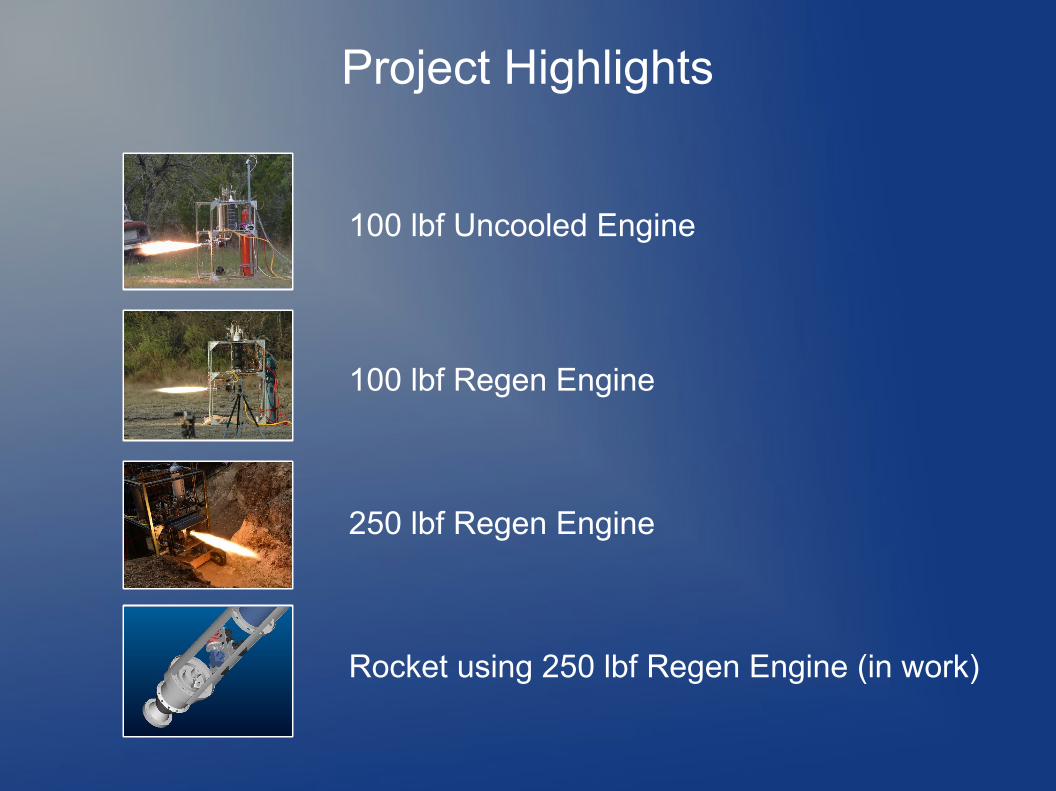
Project Highlights
100 lbf Uncooled Engine
100 lbf Regen Engine
250 lbf Regen Engine
Rocket using 250 lbf Regen Engine (in work)

250 lbf Regen Engine - Chamber
Oxidizer = LOXFuel = KerosenePressure = 265 psiaMixture ratio = 1.8MDot = 1.07 lbm/sIsp = 234 s (design)
= 210 s (actual)
Material = 6061-T6Weight = 4.0 lbm

250 lbf Regen Engine – Chamber
Diameter = 2.7 inLength = 3.9 inThroat = 0.9 inContraction ratio = 8L* = 40Number of tubes = 12Seals = Viton

250 lbf Engine – Injector v5
Pattern = 10 pair unlike impinging doublets
Material = 6061-T6
Seals = PTFE spring-energized (LOX), Viton (fuel), copper washers (igniter)

250 lbf Regen Engine – Thermal AnalysisTwh allowable = 700 degF, 6061-T6 has 10% of Ftu left
hg ≈ 0.00093 BTU/s-in^2-degR at throat, (adjustment of 1.5x based on 100 lbf data)
12-pass tube, 0.225 in dia
Chamber wall temperature: 590 degF (predicted)425 degF (measured)
Fuel exit temperature: 425 degF (predicted)260 degF (measured)

250 lbf Regen Engine – Test Data
250 lbf Regen Engine Test

250 lbf Engine Test
http://www.watzlavick.com/robert/rocket/regenChamber3/tests/20130914-run1-cam1-regen3.mp4

Augmented Spark Igniter
Propellants = GOX / KeroseneChamber pressure = 130 psiamDot = 0.0073 lbm/sMaterial = SS 304Seals = CopperSpark plug = NGK ME-8Ignition = RC-EXL

Rocket Progress
Thrust = 250 lbf sea level
Dry mass = 45-50 lbm
T/W at liftoff > 4
Burn time = 10-15 sec
Max altitude = 17-25 kft
Semi-Custom Cryo Valves
Uses ball and seats from 3/8 inch Swagelok SS-62T6
0.27 lbm (single valve w/o servo)

Rocket – Avionics
Discrete I/O
Igniter,Launch detect,Deploy chute,etc.
Analog Inputs
Pressures,Temperatures,Voltages,etc.
IMUADIS16364
TelemetryDigi XTend
Flight ComputerNetburner MOD54415
w/ uCOS RTOS
ValveActuatorsDynamixel
AX-12A
StoragemicroSD
AltimeterMSI MS5611
GPSublox 6

Questions?
See pictures, sketches, videos at:
http://www.watzlavick.com/robert/rocket

Robert's Rocket Project
Space Access '15 ConferenceApril 30, 2015
www.watzlavick.com/robert/rocket

Project Highlights
100 lbf Uncooled Engine
100 lbf Regen Engine
250 lbf Regen Engine
Rocket using 250 lbf Regen Engine (in work)
Here's a summary of the project so far.I tested the first engine in 2004. I really thought I'd fly something in just a few years. But as I got more into it, the goal became less of a one-
time event and more of a build up of capability. A lot of the fun for me is learning new things so I tend to do a lot myself instead of buying premade technologies.
Building the 100 lb uncooled engine was straightforward, right out of Sutton. It pretty much worked the first time. I realized though that an all-steel engine that can only run for a few seconds without melting wasn't going to get me very far so I started on a 100 lb regen engine. It took a couple of tries to get the injector performance up on that but then I realized that designing a vehicle around a 100 lb engine w/o active control wasn't going to work out too well (due to component weights) so I started on a larger engine – the 250 lb one.
After a fair amount of effort (those who have read my blog know what I'm talking about) I got the 250 lb engine working reliably so I've been working on a rocket for about the past year.
For this presentation, I'll go into more detail on the 250 lb engine and the rocket.

250 lbf Regen Engine - Chamber
Oxidizer = LOXFuel = KerosenePressure = 265 psiaMixture ratio = 1.8MDot = 1.07 lbm/sIsp = 234 s (design)
= 210 s (actual)
Material = 6061-T6Weight = 4.0 lbm
Making a uncooled rocket engine is easy, you just need a mill and a lathe. Making a regeneratively cooled engine that won't melt when run continuously is a bit harder. There are a lot of trade-offs between machinability, pressure drop, and cooling, and materials. One thing I did to help the cooling was to trade off some performance for lower temperature by reducing the mixture ratio from 2.2 to 1.8 (drops the chamber temperature by almost 1000 degF).
Using kerosene as the fuel is messy but at lower pressures it generates soot which coats the walls and acts like an insulator to cut down on the hot gas side heat transfer coefficient.
After debating various cooling jacket designs, I ended up with a drilled wall design using a 12-pass tube – all the fuel goes through each tube. The fuel goes in the side, turns the corner, goes down, turns again, and so on all the way around. Then it comes out the top into the injector. The 12-pass tube works great but it has about 180 psi drop across the cooling jacket.
I'm using Viton o-rings for seals and haven't seen any leakage but I change the seals out after each run.The injector is bolted on using Helicoils which turned out to be a good idea when I had a hard start the first time I ran it. I should have listened
to the advice from aRocket and switched to an ASI sooner instead of direct spark ignition. However, instead of bursting the chamber, it just ripped out all the Helicoils and I was able to clean up the holes and reuse it.

250 lbf Regen Engine – Chamber
Diameter = 2.7 inLength = 3.9 inThroat = 0.9 inContraction ratio = 8L* = 40Number of tubes = 12Seals = Viton
Here's a cross section of the engine. The profile is pretty basic but cross-drilling the cooling holes at the throat was tricky to set up. This is one of those cases where you want to measure about 10 times and cut just once.
I used Cv plugs to close out these holes out but I wouldn't recommend them since they were a pain to install. I should have used Lee plugs or Seelskrews instead.

250 lbf Engine – Injector v5
Pattern = 10 pair unlike impinging doublets
Material = 6061-T6
Seals = PTFE spring-energized (LOX), Viton (fuel), copper washers (igniter)
It took a few tries to get the injector right. The main challenge was to get everything to fit and still provide enough face cooling.The fuel comes up from the chamber into the hole and enters the manifold. Then it picks up each one of these holes, runs through the little
channels and then into the orifices. The LOX has a more direct path.For seals, I'm using Teflon spring loaded u-cup seals for LOX and Viton o-rings for the fuel. Igniter uses a copper washer at the bottom.The zigzag patterns are for face cooling. I wasn't sure how much heating the injector face would get so I assumed it would be the same as the
chamber walls as a first cut.There isn't any film cooling but I adjusted the impingement angle slightly to point it a few degrees in from straight to try and keep it away from
the walls.

250 lbf Regen Engine – Thermal AnalysisTwh allowable = 700 degF, 6061-T6 has 10% of Ftu left
hg ≈ 0.00093 BTU/s-in^2-degR at throat, (adjustment of 1.5x based on 100 lbf data)
12-pass tube, 0.225 in dia
Chamber wall temperature: 590 degF (predicted)425 degF (measured)
Fuel exit temperature: 425 degF (predicted)260 degF (measured)
For the thermal analysis, I used a spreadsheet based on textbook equations along with a 2D thermal solver.Here's the output from the thermal analysis – each of these is a cross section of one tube at the chamber, throat, and exit.I was allowing the hot wall near the throat to get up to 700 degF (aluminum melts at 1100 degF). It only has 10% of the strength left but this
design isn't dominated by strength.I would have really liked to know the hot wall temperature but that is nearly impossible to measure so I settled for 2 thermocouples embedded in
the wall in between cooling passages. I used a #6 aluminum screw with a hole drilled into it for a tiny thermocouple threaded through it and then bent over. One is located at the halfway around the jacket and the other one next to the last tube (should be the hottest).
The design turned out to be more conservative than I expected (about 165 degrees cooler) so I could probably get some more performance by bumping up the mixture ratio but at this point, it's working fine so I'm going to leave it alone.

250 lbf Regen Engine – Test Data
Here's a data plot from one of the recent tests. The red and white are tank pressures. The blue is igniter pressure, the yellow is chamber pressure, and the green is thrust.
The igniter runs at a lower pressure so you can see the transition as the main chamber pressure starts picking up. In general, the pressures and thrust are very stable.
The orange and purple traces are from the two embedded thermocouples I talked about previously. I find it interesting that they peak then come back down slightly. I suspect the unsteadiness is due to injector scrubbing of the wall portions of the soot layer. The other yellow trace is the fuel temperature at the exit of the cooling jacket and it matches the trend in the two wall thermocouples.
You can't really see the values but there are flowmeters for each of the propellant lines. That really helps because the discharge coefficients from cold water tests don't match the hot-fire performance.

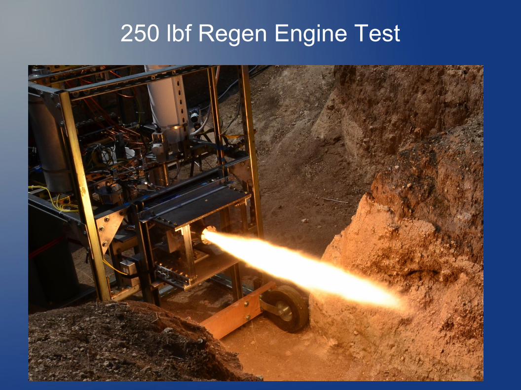
250 lbf Regen Engine Test
Here's a picture from one of the last runs on the 250 lb engine as I was dialing in the pressures to get the mixture ratio right. I added a blast shield in case it goes boom.
And, as further insurance, the whole setup is down in a 4-foot deep hole (in the backyard) which also cuts down on the noise.

250 lbf Engine Test
http://www.watzlavick.com/robert/rocket/regenChamber3/tests/20130914-run1-cam1-regen3.mp4
Here's one of the recent videos of the 250 lb engine. The clicks are from the camera shutter using a really long remote cable. The whole sequence is computer controlled so I can just sit back and watch with my hand on the big red button.
I cracked the LOX valve a couple of times while filling the tank to help chill down the plumbing and to enhance the effectiveness of the igniter.I took off the purge lines so there is some residual activity after the run.
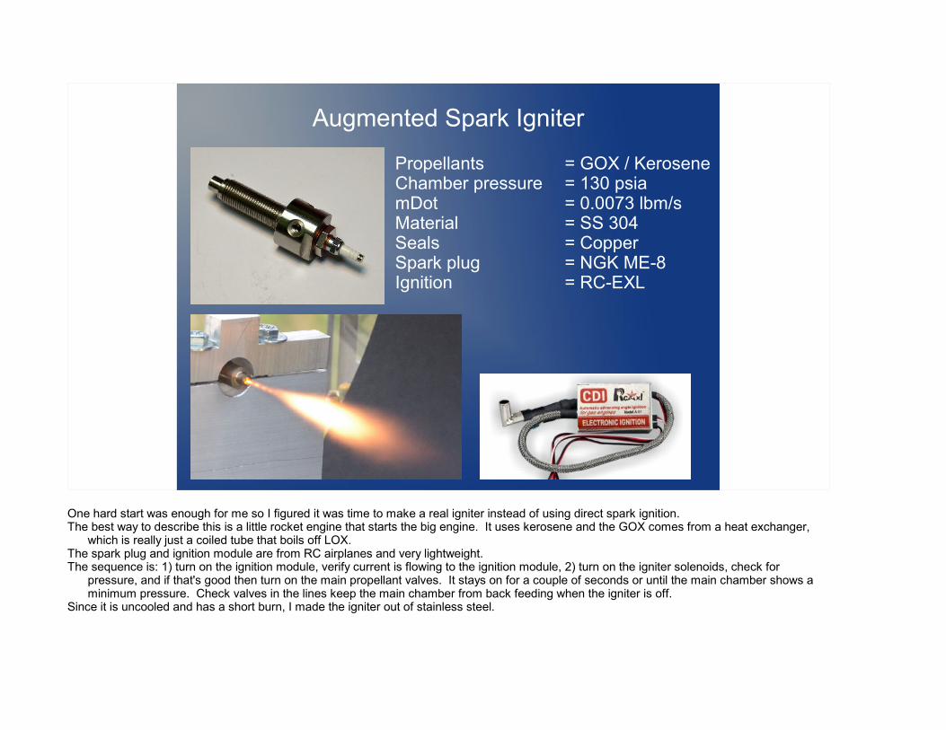
Augmented Spark Igniter
Propellants = GOX / KeroseneChamber pressure = 130 psiamDot = 0.0073 lbm/sMaterial = SS 304Seals = CopperSpark plug = NGK ME-8Ignition = RC-EXL
One hard start was enough for me so I figured it was time to make a real igniter instead of using direct spark ignition. The best way to describe this is a little rocket engine that starts the big engine. It uses kerosene and the GOX comes from a heat exchanger,
which is really just a coiled tube that boils off LOX. The spark plug and ignition module are from RC airplanes and very lightweight.The sequence is: 1) turn on the ignition module, verify current is flowing to the ignition module, 2) turn on the igniter solenoids, check for
pressure, and if that's good then turn on the main propellant valves. It stays on for a couple of seconds or until the main chamber shows a minimum pressure. Check valves in the lines keep the main chamber from back feeding when the igniter is off.
Since it is uncooled and has a short burn, I made the igniter out of stainless steel.

Rocket Progress
Thrust = 250 lbf sea level
Dry mass = 45-50 lbm
T/W at liftoff > 4
Burn time = 10-15 sec
Max altitude = 17-25 kft
The next logical step is to actually fly something. Here's what I'm aiming for with the first rocket. Assuming I can keep the weight under control, it will have a thrust-to-weight just above 4. With
a long rail and a short burn of about 10 seconds, I think I can get away with that for a first launch. Later after I get some experience under my belt, I plan to add active stabilization to keep it pointing straight up and then I can go for a much longer burn (30-60 seconds) with larger tanks and try for an altitude shot.
Here's the CAD model and photo of what I've got so far. It's a stringer and frame design with a diameter of 6 inches. I originally was going to make it 5 inches and have integral tanks but I was having trouble with the seals so for the first rocket, I decided to go
with E-sized medical oxygen cylinders, turned down on the lathe to take some wall thickness. They're rated to 2215 psi and burst over 5000 psi so I was able to take about half the wall off and still have about 3X factor of safety for the fuel tank which runs at 500 psi.
I have most of the structure figured out except for the skin. Since all the load is handled by the frames and stringers, the skin only needs to be strong enough to provide some torsional stiffness. I haven't decided yet whether to go with rolled aluminum sheet, fiberglass, or carbon fiber.

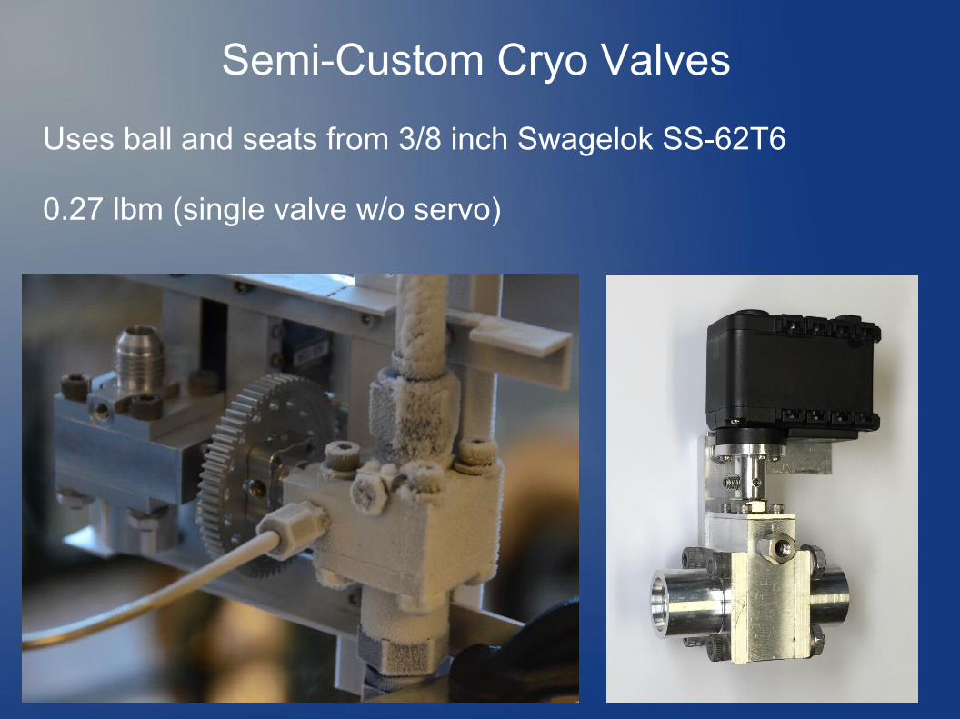
Semi-Custom Cryo Valves
Uses ball and seats from 3/8 inch Swagelok SS-62T6
0.27 lbm (single valve w/o servo)
I thought I'd show this since I spent a fair amount of time on these. One of the hardest things to miniaturize are valves, especially cryogenic valves. Commercial valves take up a lot of space with the extended stems, they weigh a lot and are hard to turn when cold.
I had some good luck with those spring energized Teflon seals so I took apart a Swagelok 3/8 ball valve and reused the ball and seats for a lightweight aluminum valve.
It's taken a few iterations and they're not perfect but they're good enough. One of the fixes was to use two opposing stem seals and pressurize the seal cavity in between.
There will be 5 of them on the vehicle, one each for the fuel and LOX main valves, one each for the tank vents, and one for the LOX fill which is a manually operated valve.
I'm using Dynamixel AX-12A servos to control the valves which have about 13 in-lb of torque. For the main valve, I linked the shafts together and used a 3:1 gear reduction for more torque as extra insurance.
Each valve weighs just over a quarter of a pound not counting the bracket or servo.

Rocket – Avionics
Discrete I/O
Igniter,Launch detect,Deploy chute,etc.
Analog Inputs
Pressures,Temperatures,Voltages,etc.
IMUADIS16364
TelemetryDigi XTend
Flight ComputerNetburner MOD54415
w/ uCOS RTOS
ValveActuatorsDynamixel
AX-12A
StoragemicroSD
AltimeterMSI MS5611
GPSublox 6
A question I get asked a lot is “why do I build so many things myself instead of buying them?” The main reason is that if I build it myself, I can get exactly what I want. Also, I get a great deal of satisfaction out of this hobby, obsession, whatever you want to call it and a big part of that is learning how do new stuff.
So, as you might expect, I'm rolling my own flight computer and telemetry system. I have most of this prototyped on the bench and I'm working on the flight software in parallel with the airframe.
I really like the Netburner products because they come with everything you need to get going including middleware (network stack, file system, timers) and a task-aware debug plugin for Eclipse. There are plenty of more powerful boards with hardware floating point (Beaglebone Black for example) but not with an RTOS and this level of support.
Right now I'm working on the ground station s/w which also doubles as a debugger for sniffing message traffic between apps.The first set of flights will be passively stabilized so there's really no need for an IMU but I want to record the raw data to use in my control model
for later. Plus, I want to see well I can use the GPS and altimeter to correct the IMU.I'll have some sort of backup tracking system onboard, probably an APRS radio on the 70 cm ham band.Several folks have suggested adding a radio link so I can manually deploy the chute from the ground.

Questions?
See pictures, sketches, videos at:
http://www.watzlavick.com/robert/rocket