Robert B. Bittner, P.E., President, Ben C. Gerwick, Inc ... · PDF fileFLOAT-IN COFFERDAMS...
14
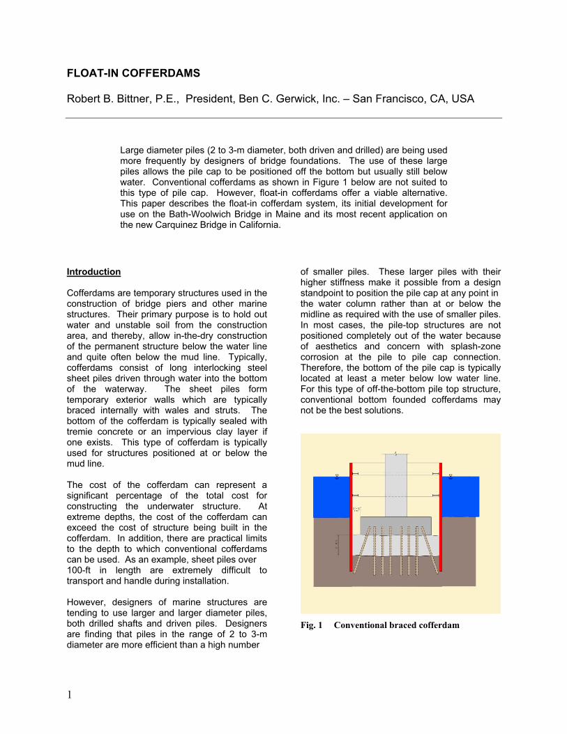
FLOAT-IN COFFERDAMS Robert B. Bittner, P.E., President, Ben C. Gerwick, Inc. – San Francisco, CA, USA Large diameter piles (2 to 3-m diameter, both driven and drilled) are being used more frequently by designers of bridge foundations. The use of these large piles allows the pile cap to be positioned off the bottom but usually still below water. Conventional cofferdams as shown in Figure 1 below are not suited to this type of pile cap. However, float-in cofferdams offer a viable alternative. This paper describes the float-in cofferdam system, its initial development for use on the Bath-Woolwich Bridge in Maine and its most recent application on the new Carquinez Bridge in California. Introduction Cofferdams are temporary structures used in the construction of bridge piers and other marine structures. Their primary purpose is to hold out water and unstable soil from the construction area, and thereby, allow in-the-dry construction of the permanent structure below the water line and quite often below the mud line. Typically, cofferdams consist of long interlocking steel sheet piles driven through water into the bottom of the waterway. The sheet piles form temporary exterior walls which are typically braced internally with wales and struts. The bottom of the cofferdam is typically sealed with tremie concrete or an impervious clay layer if one exists. This type of cofferdam is typically used for structures positioned at or below the mud line. The cost of the cofferdam can represent a significant percentage of the total cost for constructing the underwater structure. At extreme depths, the cost of the cofferdam can exceed the cost of structure being built in the cofferdam. In addition, there are practical limits to the depth to which conventional cofferdams can be used. As an example, sheet piles over 100-ft in length are extremely difficult to transport and handle during installation. However, designers of marine structures are tending to use larger and larger diameter piles, both drilled shafts and driven piles. Designers are finding that piles in the range of 2 to 3-m diameter are more efficient than a high number of smaller piles. These larger piles with their higher stiffness make it possible from a design standpoint to position the pile cap at any point in the water column rather than at or below the midline as required with the use of smaller piles. In most cases, the pile-top structures are not positioned completely out of the water because of aesthetics and concern with splash-zone corrosion at the pile to pile cap connection. Therefore, the bottom of the pile cap is typically located at least a meter below low water line. For this type of off-the-bottom pile top structure, conventional bottom founded cofferdams may not be the best solutions. Fig. 1 Conventional braced cofferdam 1
-
Upload
nguyenkhanh -
Category
Documents
-
view
215 -
download
0
Transcript of Robert B. Bittner, P.E., President, Ben C. Gerwick, Inc ... · PDF fileFLOAT-IN COFFERDAMS...
FLOAT-IN COFFERDAMS Robert B. Bittner, P.E., President, Ben C. Gerwick, Inc. – San Francisco, CA, USA
Large diameter piles (2 to 3-m diameter, both driven and drilled) are being used more frequently by designers of bridge foundations. The use of these large piles allows the pile cap to be positioned off the bottom but usually still below water. Conventional cofferdams as shown in Figure 1 below are not suited to this type of pile cap. However, float-in cofferdams offer a viable alternative. This paper describes the float-in cofferdam system, its initial development for use on the Bath-Woolwich Bridge in Maine and its most recent application on the new Carquinez Bridge in California.
Introduction Cofferdams are temporary structures used in the construction of bridge piers and other marine structures. Their primary purpose is to hold out water and unstable soil from the construction area, and thereby, allow in-the-dry construction of the permanent structure below the water line and quite often below the mud line. Typically, cofferdams consist of long interlocking steel sheet piles driven through water into the bottom of the waterway. The sheet piles form temporary exterior walls which are typically braced internally with wales and struts. The bottom of the cofferdam is typically sealed with tremie concrete or an impervious clay layer if one exists. This type of cofferdam is typically used for structures positioned at or below the mud line. The cost of the cofferdam can represent a significant percentage of the total cost for constructing the underwater structure. At extreme depths, the cost of the cofferdam can exceed the cost of structure being built in the cofferdam. In addition, there are practical limits to the depth to which conventional cofferdams can be used. As an example, sheet piles over 100-ft in length are extremely difficult to transport and handle during installation. However, designers of marine structures are tending to use larger and larger diameter piles, both drilled shafts and driven piles. Designers are finding that piles in the range of 2 to 3-m diameter are more efficient than a high number
of smaller piles. These larger piles with their higher stiffness make it possible from a design standpoint to position the pile cap at any point in the water column rather than at or below the midline as required with the use of smaller piles. In most cases, the pile-top structures are not positioned completely out of the water because of aesthetics and concern with splash-zone corrosion at the pile to pile cap connection. Therefore, the bottom of the pile cap is typically located at least a meter below low water line. For this type of off-the-bottom pile top structure, conventional bottom founded cofferdams may not be the best solutions.
Fig. 1 Conventional braced cofferdam
1
Float-In Cofferdam Concept The float-in cofferdam concept has been developed to specifically address the construction requirements for pile-top marine structures positioned below water but up off the bottom of the waterway. This concept is perhaps best described by its sequence of construction (See Figs. 2 through 8 for a plan view of a typical float-in cofferdam and construction sequence): 1. Piles or drilled shaft casings are
installed through the water. Following completion of the pile installation, they are cut off underwater.
2. Concurrent with pile installation, a thin shell of the structure is pre-fabricated at an off-site location. This thin shell (and follower cofferdam if needed) is referred to as the float-in cofferdam.
3. Following completion of fabrication, the float-in cofferdam is launched and towed to the installation site.
4. Once at site, the float-in cofferdam is lowered down on to the pre-installed piles.
5. A seal is then formed between the piles and the bottom of the float-in cofferdam, and grout (or tremie concrete) is placed to lock the float-in cofferdam to the piles.
6. The float-in cofferdam is then dewatered.
7. All remaining work is then completed in-the-dry similar to a conventional cofferdam. This includes completion of reinforcement and concrete placement in the piles or drilled shafts, and placing reinforcement and concrete for the cap and pier shaft.
8. After completion of the shaft, if a follower cofferdam was used, the cofferdam area is re-flooded and the follower cofferdam is removed for re-use on the next pier.
The float-in cofferdam method of underwater construction offers the following significant advantages over conventional cofferdams: • It can be used in essentially any water depth
where the unsupported permanent foundation piles can serve their intended function. This is in comparison to conventional bottom-founded sheet pile cofferdam systems that are limited by the
efficient lengths that standard sheet piles can be rolled, shipped and handled at the site.
• It offers the potential advantage of a reduced
construction schedule by allowing the pile installation work to commence immediately rather than wait until the cofferdam has been designed, sheet piles ordered, bracing frames fabricated and cofferdams installed. This is a significant time advantage in that pile installation work is typically on the critical path and is the most common cause of delay on a marine construction project. Time is of course required to design, build and launch the float-in cofferdam. But all of this work can be performed concurrent with the pile installation work.
• This cofferdam method can offer significant
cost savings by:
1) eliminating or reducing the length of sheet piles,
2) eliminating the conventional tremie seal that is used to resist hydrostatic uplift,
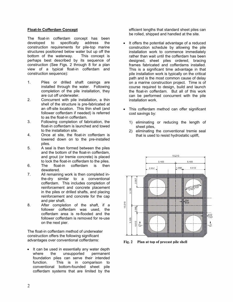
Fig. 2 Plan at top of precast pile shell
2

• • rk is
Fig. 3
Fig. 4 Stage 2 – Launch and position float-in
cofferdam
Stage 1 – Pile installation and cut off
Fig. 5 Stage 3 – Land cofferdam, seal pile connection and place tremie concrete Fig. 6 Stage 4 – Dewater cofferdam and
construct pile cap
Fig. 8 age 6 – Strip follower StFig. 7 Stage 5 – Construct pier shaft
3
3) allowing the pile cap fabrication operation to be performed more efficiently at a centrally located fabrication site on shore or at dock side rather than at multiple in-water cofferdam locations, and
4) allowing for more competitive pricing for material and labor by enlarging the geographical area over which the shells can be fabricated.
These cost savings are offset to some degree by the cost of the offsite fabrication and launch facility, however these are usually less than the cost associated with the savings listed above.
• It can reduce construction risk by minimizing
the amount of time that the work is exposed to severe whether and fluctuating water levels. In addition, the critical operations such as float-in, positioning and landing can be timed to fit optimum weather and water level conditions.
• It can provided higher quality for the underwater concrete by allowing the exterior of the pile cap to be precast on shore in ideal conditions under tighter quality control.
• From a design point, this system allows elimination of the conventional tremie concrete seal. This reduces dead weight of the structure, and in areas of seismic risk, significantly reduces seismic loadings as well.
Float-In Cofferdam Features The float-in cofferdam concept has the following typical features: • Off-site prefabrication – A thin steel or
concrete shell which forms the exterior of the pile cap is pre-fabricated in a dry dock or on the deck of a barge with the barge positioned at dock side to allow construction support from a shore based crane. (See Figs. 2 and 4 for details of the float-in pile-cap shell used on the Bath-Woolwich Bridge.) This offsite fabrication is typically performed at a central location that allows an efficient flow of materials and effective monitoring for quality control. If the construction site is affected by severe weather conditions, it may be preferable to locate the fabrication facility indoors where higher labor efficiency can be
obtained. Additionally, selection of the fabrication site should take into consideration the method of launching. (See launch method below for specific details.)
• Temporary bulkheads – Temporary
bulkheads are typically steel ribbed elements used to close off openings in the shell structure, making the shell water tight and allowing it to float after launch. These bulkheads are typically salvaged and re-used on following caps. The bulkheads are typically bolted in place and use compressible neoprene or rubber seals at the mating surfaces to maintain water tightness. (See Figs. 23 and 24 for a view of the temporary bulkheads used on the Carquinez Bridge float-in cofferdams.)
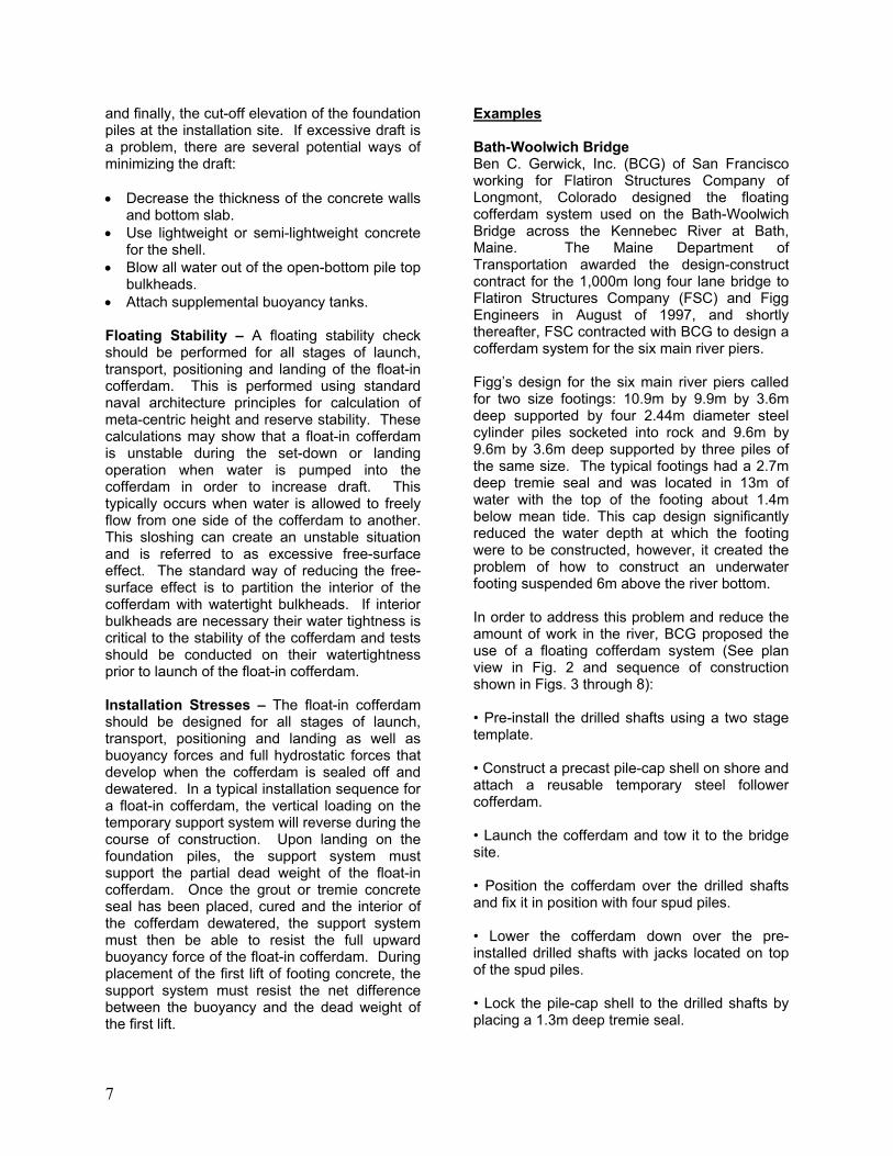
• Pile-top bulkheads – Pile-top bulkheads can
be classified as a special type of temporary bulkhead. They are inverted open-bottomed cans that are centered directly over the top of the circular openings in the bottom of the pre-fabricated shells. They allow the foundation piles to penetrate up into the interior of the shell while maintaining the watertight integrity of the float-in cofferdam. (See Figs. 10 and 22 for examples of pile-top bulkheads used on the Bath-Woolwich and Carquinez bridges respectively.) These blockouts are of course watertight except for the open bottom and can act as individual ballast compartments if compressed air hoses are attached to each compartment. By regulating the air pressure in each pile-top blockout, it is possible to level or trim the float-in cofferdam during launch and transport. (See Fig. 12 for a view of the air piping used on the Bath-Woolwich Bridge.)
• Follower steel cofferdams – Follower
cofferdams are required for pile-top structures that are positioned completely under water. Follower cofferdams extend the height of the prefabricated shell walls sufficiently to allow the pile cap to be lowered to final grade without allowing water to overtop the cofferdam. These are typically stripped at completion of the pier and re-used on following piers. (See Figs. 14, 15 and 18 for pictures of the follower cofferdam used on the Bath-Woolwich Bridge.) These follower cofferdams are very similar to conventional sheet pile cofferdams. They have the same
4
type of internal bracing consisting of steel wale frames and struts. The walls of the follower cofferdams can be steel ribbed panels, corrugated panels or even conventional steel sheet piles. All three types typically terminate in a flat bottom plate that bolts directly to the top of the pile-cap shell structure.
• Concurrent foundation and pile-cap shell
construction – The float-in cofferdam method of construction allows installation of foundation piles to run concurrently with fabrication of the pile-cap shell. This feature allows for a shorter construction schedule compared to conventional pier construction.
• Temporary pile-top cofferdams for
underwater cut off of piles – In order to float-in over the pre-installed piles, it is necessary to cut the permanent piles off to grade under water. This can be performed with divers, however it is expensive and risky to do so. It is preferable to cut the piles off in-the-dry using a temporary cofferdam that slips down around the permanent pile and seals to the side of the pile, thus allowing the annulus between the outer cofferdam and the exterior wall of the pile to be dewatered. Once the interior of the pile and the annulus have been dewatered above the cut off point, a worker is lowered into the interior of the pile, and the pile is cut off to precise grade. An alternate method which can be used when the drill casings are torqued into position is to use drilled shaft casings that have a reverse torque disconnect built into the wall of the casing. The disconnect point is pre-determined at each pile location, and each casings is fabricated with a disconnect at a pre-planned location. This method was used on the drilled shafts for the Bath-Woolwich Bridge.
• Cofferdam launch method – There are
many different potential ways to launch the float-in cofferdams. The launch method is usually tied to the method and location of the shell fabrication or casting. If the shell is fabricated in a dry dock, launching is performed by flooding the dry dock and exiting through a removable gate at the entrance to the dry dock. If the shell is cast on the deck of a flat-deck barge, it is typically launched by ballasting the barge out from under the shell and allowing the shell to float
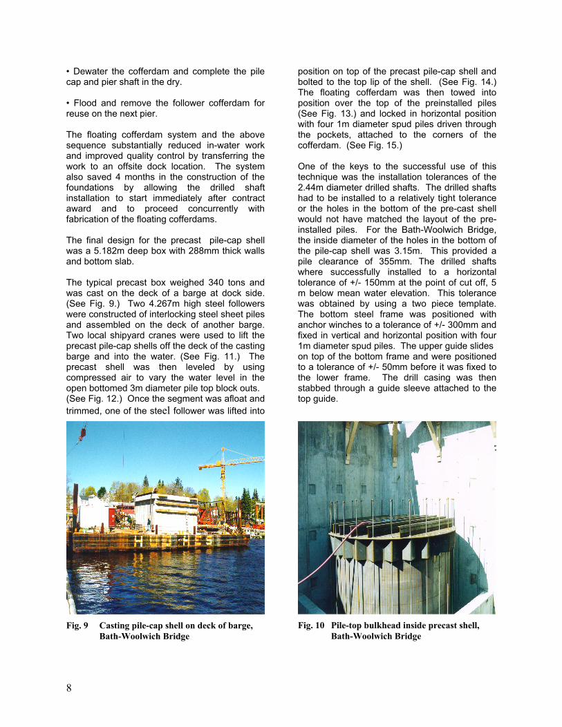
free. If this method is used, special consideration needs to be given to maintaining stability of the barge during all ballasting operation. The stability analysis for the launch operations should be performed and monitored by an engineer experienced at performing stability calculations or by a naval architect. The stability can be controlled by setting one end of the barge down on a pre-leveled bottom, or by attaching wing-tanks to the barge in order to provide sufficient water plane during all stages of launch. If the shell is light enough and heavy lift equipment is available, the shell can be lifted off and set in the water. (For an example of this method, see Fig. 11 for a photo of the float-in pile-cap shell being lifted off the deck of the casting barge at the Bath Ship Yard. If launch ways are available close to the installation site, they cap provide an alternate launch method.
• Method of transport – Tugs are typically
used to assist the floating cofferdams during their transit to the installation site.
• Positioning and guidance system –
Positioning and guidance systems are needed during the mating of the float-in cofferdam to the pre-installed foundation piles. These are particularly important when the tops of the foundation piles are several meters below water and out of site. These systems include mooring lines, anchors, and tapered guide structures to direct the cofferdam onto the permanent support piles.
• Temporary ballast system – In order to sink
the prefabricated pile-cap shell down to the cut-off piles, it is necessary to partially flood the cofferdam. During the sinking operation the cofferdam should be maintained relatively level. This requires an ability to add water to different areas of the pile-cap shell. The ballast system performs this function.
• Temporary support system – In order to
land the float-in cofferdam on the cut- off piles, a means of load transfer must be developed to carry the partial dead weight of the cofferdam. The required capacity for the system is relatively low and is only temporary until it is replaced by the tremie or grout closure pour. (See Figs. 19 and 20 for details of the temporary support beam,
5
shown in yellow, used as the temporary landing support on the Carquinez Bridge.)
• Bottom sealing system – After landing of
the float-in cofferdam, the foundation piles typically penetrate up into the bottom of the pre-fabricated pile- cap shell, and a grout or concrete placement is made in the bottom of the shell to lock the shell to the foundation piles. In order to place the grout or tremie concrete, it is first necessary to seal the bottom of the annulus between the outside wall of the pile and the hole in the bottom of the pre-fabricated shell. This seal does not have to resist the total hydrostatic head at that point but only the buoyant head of a few feet of the grout or tremie concrete. (See Fig. 20 for details of the temporary sealing system used on the Carquinez Bridge.)
• Grout or tremie closure – The grout or
tremie concrete placement is the primary sealing system to allow dewatering of the float-in cofferdam. It is also the primary load transfer element to resist the uplift buoyancy of the cofferdam after the cofferdam is dewatered and to support any net downward load immediately after placement of the first lift of concrete in the pile-cap shell. (See Fig. 5 for a schematic of the tremie concrete closure that was used on the Bath-Woolwich Bridge float-in cofferdams.)
Specific Considerations In The Design Of Float-In Cofferdams Tolerances – The float-in cofferdam method requires the mating of the float-in cofferdam to the top of the pre-installed piles. In order for this mating to succeed without punching a hole in the bottom of the float-in cofferdam, it is essential that the pile be properly located within a specified tolerance. Piles installed from floating equipment on anchor lines or spuds can typically meet installation tolerances of +/- 15 cm horizontally at the surface of the water and 1% in verticality. Piles installed through a bottom founded template can be installed to a tolerance of typically 6 cm at the surface of the water and 0.5% verticality. These tolerances need to be taken into account when designing the net clearance of the openings in the bottom of the float-in cofferdam relative to outside diameter of the pile. These clearances
need to be large enough to take into account possible misalignment of the piles while maintaining the structural integrity of the bottom slab and providing a void space that can be effectively sealed off for grouting or tremie placement. The cut-off tolerance of the piles under water using a pile top cofferdam for access is typically about +/- 3mm. This tolerance may be necessary if the support bearing on landing is directly onto the pile cut-off surface. However an alternate way of leveling the float-in cofferdams after landing is to use flat-jacks attached at the bearing points in the float-in cofferdam. These jacks should be plumbed together to allow a three point landing system. Water Tightness – During launch, transport and positioning of the pile-top cofferdams it is essential that the inflow of water into the cofferdam be controlled at all times. The joints between the float-in pile top structure and water tight bulkheads, follower cofferdam and pile top blockouts are all typically fitted with strips of compressible neoprene or rubber. These continuous strips are typically 5 to 8 cm wide and 1 cm thick. The durometer of the seal should be approximately 40 to 60. Compression of the sealing strip is provided by bolts on a typically about 30 cm. The strips should be positioned to compress with application of increased bolt tension and increased hydrostatic load on the outside of the cofferdam. If conventional steel sheet piles are used for the follower cofferdam, the interlocks should be treated with hydrophilic strips prior to attachment to the float-in cofferdam. If ballasting operations during sit-down operations require internal bulkheads to maintain stability, the water tightness of these bulkheads is essential and should be treated with the same level of importance as exterior bulkheads. Leaking interior bulkheads can cause loss of stability during ballasting operations and result in loss of the floating pile-cap shell. Draft Limitations – There may be several factors that will limit the allowable draft of the float-in cofferdam at launch. These may include the depth of dry dock where the float-in cofferdam is being fabricated, the depth of the navigation channel leading to the installation site
6
and finally, the cut-off elevation of the foundation piles at the installation site. If excessive draft is a problem, there are several potential ways of minimizing the draft: • Decrease the thickness of the concrete walls
and bottom slab. • Use lightweight or semi-lightweight concrete
for the shell. • Blow all water out of the open-bottom pile top
bulkheads. • Attach supplemental buoyancy tanks. Floating Stability – A floating stability check should be performed for all stages of launch, transport, positioning and landing of the float-in cofferdam. This is performed using standard naval architecture principles for calculation of meta-centric height and reserve stability. These calculations may show that a float-in cofferdam is unstable during the set-down or landing operation when water is pumped into the cofferdam in order to increase draft. This typically occurs when water is allowed to freely flow from one side of the cofferdam to another. This sloshing can create an unstable situation and is referred to as excessive free-surface effect. The standard way of reducing the free-surface effect is to partition the interior of the cofferdam with watertight bulkheads. If interior bulkheads are necessary their water tightness is critical to the stability of the cofferdam and tests should be conducted on their watertightness prior to launch of the float-in cofferdam. Installation Stresses – The float-in cofferdam should be designed for all stages of launch, transport, positioning and landing as well as buoyancy forces and full hydrostatic forces that develop when the cofferdam is sealed off and dewatered. In a typical installation sequence for a float-in cofferdam, the vertical loading on the temporary support system will reverse during the course of construction. Upon landing on the foundation piles, the support system must support the partial dead weight of the float-in cofferdam. Once the grout or tremie concrete seal has been placed, cured and the interior of the cofferdam dewatered, the support system must then be able to resist the full upward buoyancy force of the float-in cofferdam. During placement of the first lift of footing concrete, the support system must resist the net difference between the buoyancy and the dead weight of the first lift.
Examples Bath-Woolwich Bridge Ben C. Gerwick, Inc. (BCG) of San Francisco working for Flatiron Structures Company of Longmont, Colorado designed the floating cofferdam system used on the Bath-Woolwich Bridge across the Kennebec River at Bath, Maine. The Maine Department of Transportation awarded the design-construct contract for the 1,000m long four lane bridge to Flatiron Structures Company (FSC) and Figg Engineers in August of 1997, and shortly thereafter, FSC contracted with BCG to design a cofferdam system for the six main river piers. Figg’s design for the six main river piers called for two size footings: 10.9m by 9.9m by 3.6m deep supported by four 2.44m diameter steel cylinder piles socketed into rock and 9.6m by 9.6m by 3.6m deep supported by three piles of the same size. The typical footings had a 2.7m deep tremie seal and was located in 13m of water with the top of the footing about 1.4m below mean tide. This cap design significantly reduced the water depth at which the footing were to be constructed, however, it created the problem of how to construct an underwater footing suspended 6m above the river bottom. In order to address this problem and reduce the amount of work in the river, BCG proposed the use of a floating cofferdam system (See plan view in Fig. 2 and sequence of construction shown in Figs. 3 through 8): • Pre-install the drilled shafts using a two stage template. • Construct a precast pile-cap shell on shore and attach a reusable temporary steel follower cofferdam. • Launch the cofferdam and tow it to the bridge site. • Position the cofferdam over the drilled shafts and fix it in position with four spud piles. • Lower the cofferdam down over the pre-installed drilled shafts with jacks located on top of the spud piles. • Lock the pile-cap shell to the drilled shafts by placing a 1.3m deep tremie seal.
7
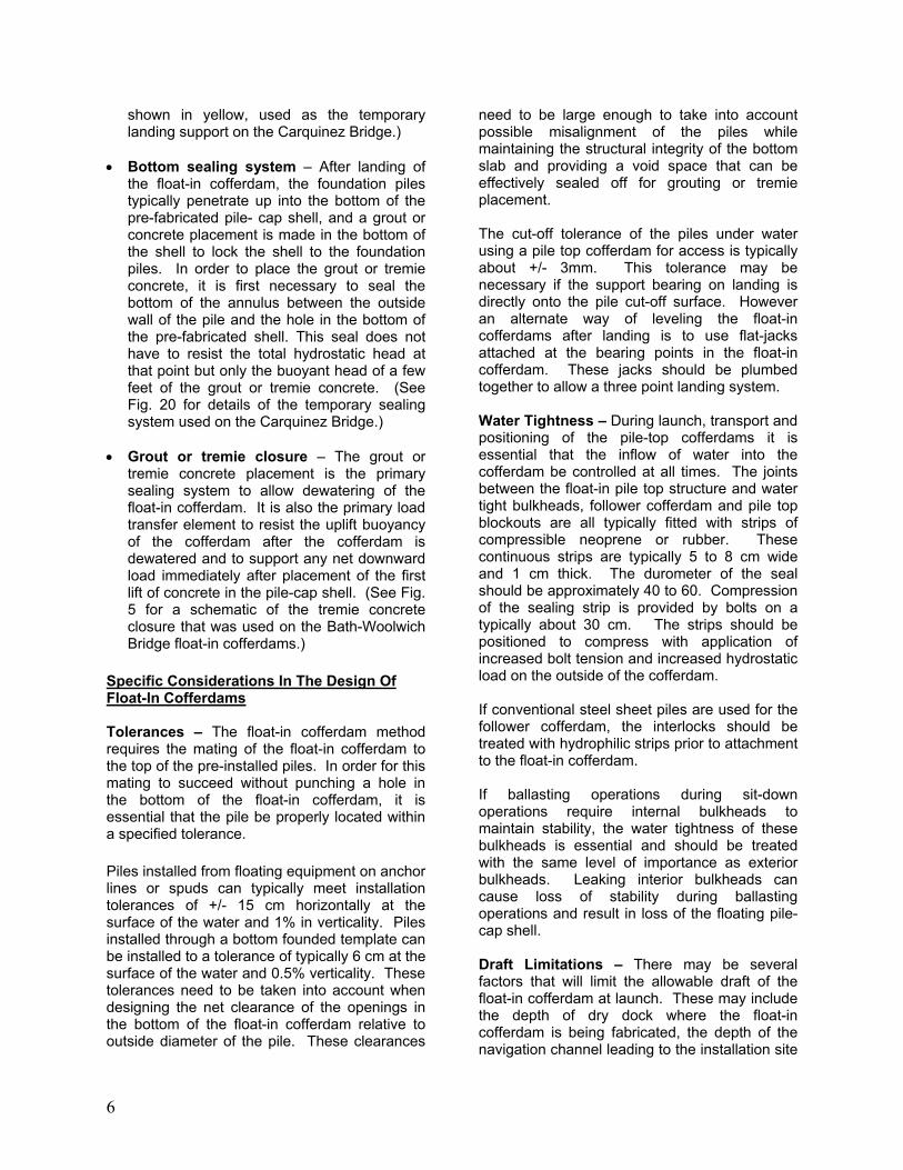
• Dewater the cofferdam and complete the pile cap and pier shaft in the dry. • Flood and remove the follower cofferdam for reuse on the next pier. The floating cofferdam system and the above sequence substantially reduced in-water work and improved quality control by transferring the work to an offsite dock location. The system also saved 4 months in the construction of the foundations by allowing the drilled shaft installation to start immediately after contract award and to proceed concurrently with fabrication of the floating cofferdams. The final design for the precast pile-cap shell was a 5.182m deep box with 288mm thick walls and bottom slab. The typical precast box weighed 340 tons and was cast on the deck of a barge at dock side. (See Fig. 9.) Two 4.267m high steel followers were constructed of interlocking steel sheet piles and assembled on the deck of another barge. Two local shipyard cranes were used to lift the precast pile-cap shells off the deck of the casting barge and into the water. (See Fig. 11.) The precast shell was then leveled by using compressed air to vary the water level in the open bottomed 3m diameter pile top block outs. (See Fig. 12.) Once the segment was afloat and trimmed, one of the steel follower was lifted into
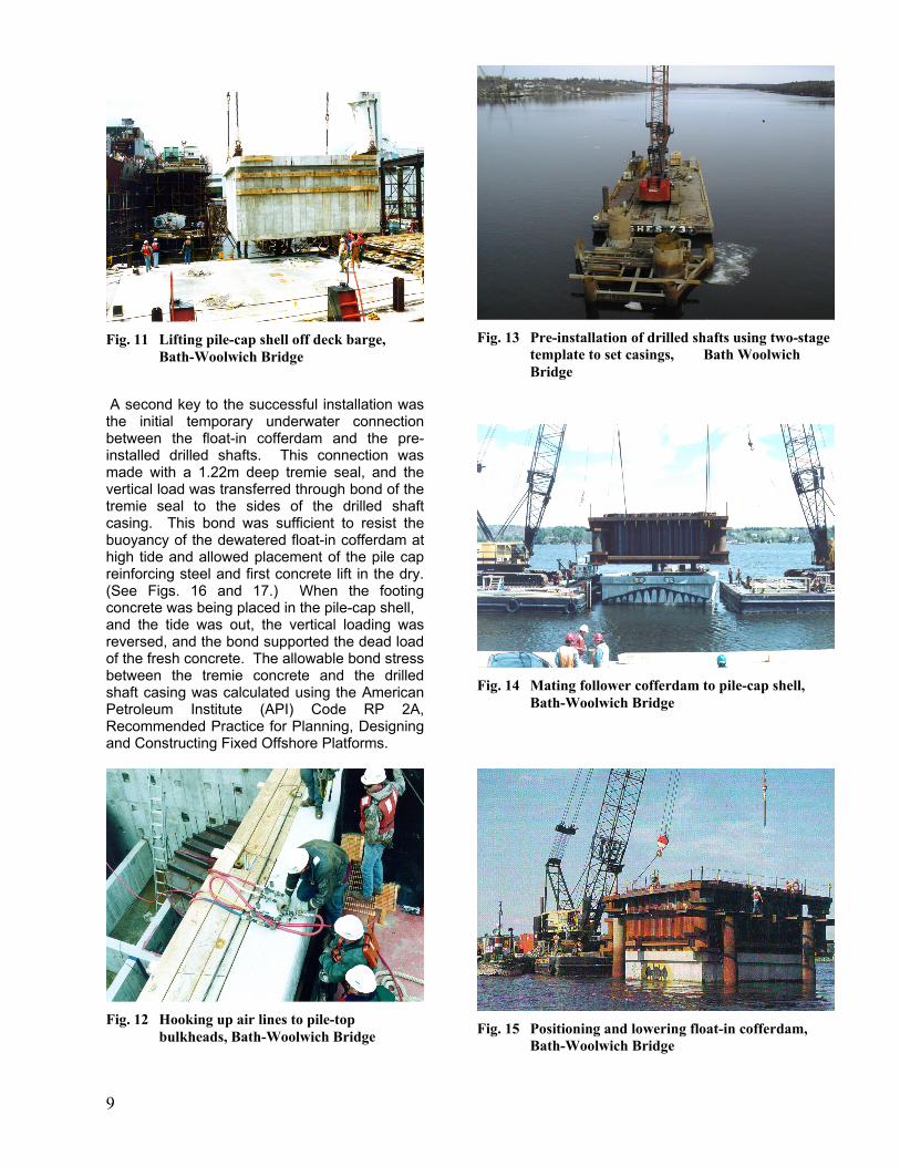
position on top of the precast pile-cap shell and bolted to the top lip of the shell. (See Fig. 14.) The floating cofferdam was then towed into position over the top of the preinstalled piles (See Fig. 13.) and locked in horizontal position with four 1m diameter spud piles driven through the pockets, attached to the corners of the cofferdam. (See Fig. 15.) One of the keys to the successful use of this technique was the installation tolerances of the 2.44m diameter drilled shafts. The drilled shafts had to be installed to a relatively tight tolerance or the holes in the bottom of the pre-cast shell would not have matched the layout of the pre-installed piles. For the Bath-Woolwich Bridge, the inside diameter of the holes in the bottom of the pile-cap shell was 3.15m. This provided a pile clearance of 355mm. The drilled shafts where successfully installed to a horizontal tolerance of +/- 150mm at the point of cut off, 5 m below mean water elevation. This tolerance was obtained by using a two piece template. The bottom steel frame was positioned with anchor winches to a tolerance of +/- 300mm and fixed in vertical and horizontal position with four 1m diameter spud piles. The upper guide slides on top of the bottom frame and were positioned to a tolerance of +/- 50mm before it was fixed to the lower frame. The drill casing was then stabbed through a guide sleeve attached to the top guide.
Fig. 9 Casting pile-cap shell on deck of barge, Bath-Woolwich Bridge
Fig. 10 Pile-top bulkhead inside precast shell, Bath-Woolwich Bridge
8
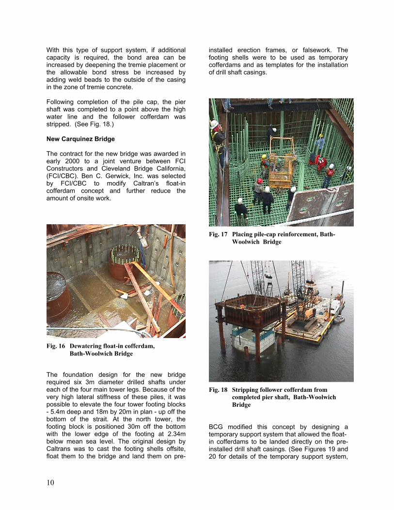
A second key to the successful installation was the initial temporary underwater connection between the float-in cofferdam and the pre-installed drilled shafts. This connection was made with a 1.22m deep tremie seal, and the vertical load was transferred through bond of the tremie seal to the sides of the drilled shaft casing. This bond was sufficient to resist the buoyancy of the dewatered float-in cofferdam at high tide and allowed placement of the pile cap reinforcing steel and first concrete lift in the dry. (See Figs. 16 and 17.) When the footing concrete was being placed in the pile-cap shell, and the tide was out, the vertical loading was reversed, and the bond supported the dead load of the fresh concrete. The allowable bond stress between the tremie concrete and the drilled shaft casing was calculated using the American Petroleum Institute (API) Code RP 2A, Recommended Practice for Planning, Designing and Constructing Fixed Offshore Platforms.
Fig. 13 Pre-installation of drilled shafts using two-stage template to set casings, Bath Woolwich Bridge
Fig. 11 Lifting pile-cap shell off deck barge, Bath-Woolwich Bridge
Fig. 14 Mating follower cofferdam to pile-cap shell, Bath-Woolwich Bridge
Fig. 15 Positioning and lowering float-in cofferdam, Bath-Woolwich Bridge
Fig. 12 Hooking up air lines to pile-top bulkheads, Bath-Woolwich Bridge
9
With this type of support system, if additional capacity is required, the bond area can be increased by deepening the tremie placement or the allowable bond stress be increased by adding weld beads to the outside of the casing in the zone of tremie concrete. Following completion of the pile cap, the pier shaft was completed to a point above the high water line and the follower cofferdam was stripped. (See Fig. 18.) New Carquinez Bridge The contract for the new bridge was awarded in early 2000 to a joint venture between FCI Constructors and Cleveland Bridge California, (FCI/CBC). Ben C. Gerwick, Inc. was selected by FCI/CBC to modify Caltran’s float-in cofferdam concept and further reduce the amount of onsite work.
The foundation design for the new bridge required six 3m diameter drilled shafts under each of the four main tower legs. Because of the very high lateral stiffness of these piles, it was possible to elevate the four tower footing blocks - 5.4m deep and 18m by 20m in plan - up off the bottom of the strait. At the north tower, the footing block is positioned 30m off the bottom with the lower edge of the footing at 2.34m below mean sea level. The original design by Caltrans was to cast the footing shells offsite, float them to the bridge and land them on pre-
installed erection frames, or falsework. The footing shells were to be used as temporary cofferdams and as templates for the installation of drill shaft casings.
Fig. 17 Placing pile-cap reinforcement, Bath-Woolwich Bridge
Fig. 16 Dewatering float-in cofferdam, Bath-Woolwich Bridge
Fig. 18 Stripping follower cofferdam from completed pier shaft, Bath-Woolwich Bridge
BCG modified this concept by designing a temporary support system that allowed the float- in cofferdams to be landed directly on the pre-installed drill shaft casings. (See Figures 19 and 20 for details of the temporary support system,
10
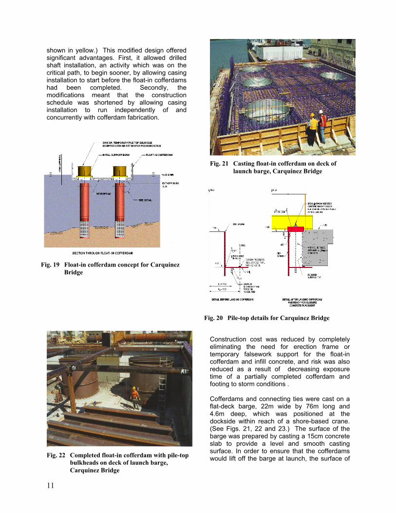
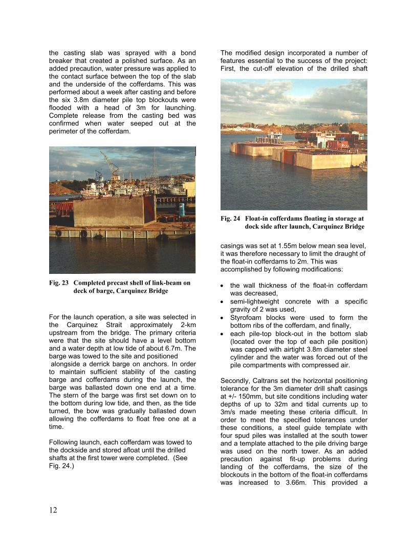
Fig. 21 Casting float-in cofferdam on deck of launch barge, Carquinez Bridge
shown in yellow.) This modified design offered significant advantages. First, it allowed drilled shaft installation, an activity which was on the critical path, to begin sooner, by allowing casing installation to start before the float-in cofferdams had been completed. Secondly, the modifications meant that the construction schedule was shortened by allowing casing installation to run independently of and concurrently with cofferdam fabrication.
Fig. 19 Float-in cofferdam concept for Carquinez Bridge
Fig. 20 Pile-top details for Carquinez Bridge
Construction cost was reduced by completely eliminating the need for erection frame or temporary falsework support for the float-in cofferdam and infill concrete, and risk was also reduced as a result of decreasing exposure time of a partially completed cofferdam and footing to storm conditions . Cofferdams and connecting ties were cast on a flat-deck barge, 22m wide by 76m long and 4.6m deep, which was positioned at the dockside within reach of a shore-based crane. (See Figs. 21, 22 and 23.) The surface of the barge was prepared by casting a 15cm concrete slab to provide a level and smooth casting surface. In order to ensure that the cofferdams would lift off the barge at launch, the surface of
11
Fig. 22 Completed float-in cofferdam with pile-top bulkheads on deck of launch barge, Carquinez Bridge
the casting slab was sprayed with a bond breaker that created a polished surface. As an added precaution, water pressure was applied to the contact surface between the top of the slab and the underside of the cofferdams. This was performed about a week after casting and before the six 3.8m diameter pile top blockouts were flooded with a head of 3m for launching. Complete release from the casting bed was confirmed when water seeped out at the perimeter of the cofferdam.
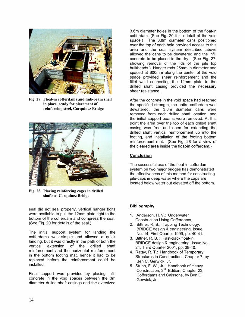
For the launch operation, a site was selected in the Carquinez Strait approximately 2-km upstream from the bridge. The primary criteria were that the site should have a level bottom and a water depth at low tide of about 6.7m. The barge was towed to the site and positioned alongside a derrick barge on anchors. In order to maintain sufficient stability of the casting barge and cofferdams during the launch, the barge was ballasted down one end at a time. The stern of the barge was first set down on to the bottom during low tide, and then, as the tide turned, the bow was gradually ballasted down allowing the cofferdams to float free one at a time. Following launch, each cofferdam was towed to the dockside and stored afloat until the drilled shafts at the first tower were completed. (See Fig. 24.)
The modified design incorporated a number of features essential to the success of the project: First, the cut-off elevation of the drilled shaft
casings was set at 1.55m below mean sea level,
Fig. 24 Float-in cofferdams floating in storage at dock side after launch, Carquinez Bridge
Fig. 23 Completed precast shell of link-beam on deck of barge, Carquinez Bridge
it was therefore necessary to limit the draught of the float-in cofferdams to 2m. This was accomplished by following modifications: • the wall thickness of the float-in cofferdam
was decreased, • semi-lightweight concrete with a specific
gravity of 2 was used, • Styrofoam blocks were used to form the
bottom ribs of the cofferdam, and finally, • each pile-top block-out in the bottom slab
(located over the top of each pile position) was capped with airtight 3.8m diameter steel cylinder and the water was forced out of the pile compartments with compressed air.
Secondly, Caltrans set the horizontal positioning tolerance for the 3m diameter drill shaft casings at +/- 150mm, but site conditions including water depths of up to 32m and tidal currents up to 3m/s made meeting these criteria difficult. In order to meet the specified tolerances under these conditions, a steel guide template with four spud piles was installed at the south tower and a template attached to the pile driving barge was used on the north tower. As an added precaution against fit-up problems during landing of the cofferdams, the size of the blockouts in the bottom of the float-in cofferdams was increased to 3.66m. This provided a
12

theoretical clearance around the pre-installed drilled shafts of 330mm. Third, the system for cutting off the drilled shafts under water included a 4.5m diameter cylindrical cofferdam that fitted over the top of the drilled shaft. The cofferdam sealed to the casing at about 1m below cut-off elevation by means of an inflatable rubber O-ring that fit inside a circular recess at the bottom of the cofferdam. Following inflation of the seal, the cofferdam was dewatered and the drilled shaft casing was cut off in the dry to a precise elevation. This cut-off cofferdam also allowed access for welding a steel ring to the exterior of the casing; the ring was used to provide the watertight seal between the float-in cofferdam and the drilled shaft casings. It also provided the necessary shear resistance for the support of the cofferdam during the concrete infill operation. (See Figs. 19 and 20 for details of the bottom seal.) Fourth, high tidal currents in the Carquinez Strait meant there was only about an hour of slack tide during which the cofferdams could be landed. Hence it was necessary to install a guide system to allow rapid positioning and landing. Because the water was more than 32m deep, the guide system was attached directly to the 3m diameter drilled shaft casings. The guides were L-shaped wide flange brackets attached to the casing just below the landing support bracket and extended above high tide so they could be used for visual positioning of the cofferdams. (See Fig. 25.)
The 4.5m diameter cylindrical cofferdam allowed the tops of the casings to be cut off to a precise
elevation. This provided an excellent bearing surface for the landing of the cofferdams. Caltrans’ initial design showed the top of the casing protruding through the 3.2m diameter holes in the bottom of the cofferdam and cut off flush with the bottom floor of the precast cofferdam. Landing support was provided by steel beams spanning across four of the bottom slab openings and bolted flush to the floor of the precast cofferdam. The actual bearing surface was the top edge of the drilled shaft casing and the underside of the steel beam. (See Figs. 19 and 20 for details of the bearing surface.)
Fig. 26 Landed float-in cofferdam and accessing seals through through pile-top bulkheads, Carquinez Bridge
Fig. 25 Positioning and landing float-in cofferdam at N. Tower, Carquinez Bridge
In order to dewater the cofferdam it was necessary to create a watertight seal between the six drilled shaft casings and oversized holes in the bottom of the cofferdam. This was accomplished by pre-welding doughnut-shaped steel rings - 12mm thick by 700mm wide - to the casings just below the cut-off elevation, at the finished bottom elevation of the cofferdam. These plates were attached in-the-dry by using the same 4.5m diameter cofferdam used for casing cut-off. At the outer edge of the steel doughnut, an inflatable O-ring was bonded to the plate. As the void space around each casing was dewatered the hydrostatic pressure pushed up on the bottom of the steel plates and the rubber O-rings provided the necessary seal. In areas where the
13
seal did not seal properly, vertical hanger bolts were available to pull the 12mm plate tight to the bottom of the cofferdam and compress the seal. (See Fig. 20 for details of the seal.) The initial support system for landing the cofferdams was simple and allowed a quick landing, but it was directly in the path of both the vertical extension of the drilled shaft reinforcement and the horizontal reinforcement in the bottom footing mat, hence it had to be replaced before the reinforcement could be installed. Final support was provided by placing infill concrete in the void spaces between the 3m diameter drilled shaft casings and the oversized
3.6m diameter holes in the bottom of the float-in cofferdam. (See Fig. 20 for a detail of the void space.) The 3.8m diameter cans positioned over the top of each hole provided access to this area and the seal system described above allowed the cans to be dewatered and the infill concrete to be placed in-the-dry. (See Fig. 27, showing removal of the lids of the pile top bulkheads.) Hanger rods 25mm in diameter and spaced at 600mm along the center of the void space provided shear reinforcement and the fillet weld connecting the 12mm plate to the drilled shaft casing provided the necessary shear resistance.
Fig. 27 Float-in cofferdams and link-beam shell in place, ready for placement of reinforcing steel, Carquinez Bridge
Fig. 28 Placing reinforcing cages in drilled shafts at Carquinez Bridge
After the concrete in the void space had reached the specified strength, the entire cofferdam was dewatered, the 3.8m diameter cans were removed from each drilled shaft location, and the initial support beams were removed. At this point the area over the top of each drilled shaft casing was free and open for extending the drilled shaft vertical reinforcement up into the footing, and installation of the footing bottom reinforcement mat. (See Fig. 28 for a view of the cleared area inside the float-in cofferdam.) Conclusion The successful use of the float-in cofferdam system on two major bridges has demonstrated the effectiveness of this method for constructing pile-caps in deep water where the caps are located below water but elevated off the bottom.
Bibliography 1. Anderson, H. V.: Underwater Construction Using Cofferdams, 2. Bittner, R. B.: Tapping Technology, BRIDGE design & engineering, Issue No. 14, First Quarter 1999, pp. 40-41. 3. Bittner, R. B. : Fast-track float-in, BRIDGE design & engineering, Issue No. 24, Third Quarter 2001, pp. 38-40. 4. Ratay, R. T.: Handbook of Temporary Structures in Construction , Chapter 7, by Ben C. Gerwick, Jr. 5. Stubb, F. W., Jr.: Handbook of Heavy Construction, 3rd Edition, Chapter 23, Cofferdams and Caissons, by Ben C. Gerwick, Jr.
14