Road Design Manual - Chapter 12 - Jboss Home Page · · 2017-08-08MICHIGAN DESIGN MANUAL ROAD...
55
MICHIGAN DESIGN MANUAL ROAD DESIGN CHAPTER 12 INDEX MISCELLANEOUS ROADS 12.01 SERVICE ROADS 12.01.01 General 12.01.02 Local Jurisdiction 12.01.03 Design Speed 12.01.04 Design Considerations 12.01.05 Detroit Metropolitan Area 12.02 LOCAL ROADS AND STREETS 12.02.01 References 12.02.02 General 12.02.03 Intersection Approaches 12.02.04 City of Detroit A. Sodding B. Grades C. Temporary Roads D. Sidewalks E. Curb Returns F. Utilities G. Alleys H. SCANDI 12.03 TURNBACKS 12.03.01 Reference 12.03.02 General 12.03.03 Turnback Letter
Transcript of Road Design Manual - Chapter 12 - Jboss Home Page · · 2017-08-08MICHIGAN DESIGN MANUAL ROAD...

MICHIGAN DESIGN MANUAL
ROAD DESIGN
CHAPTER 12
INDEX
MISCELLANEOUS ROADS 12.01 SERVICE ROADS 12.01.01 General 12.01.02 Local Jurisdiction 12.01.03 Design Speed 12.01.04 Design Considerations 12.01.05 Detroit Metropolitan Area 12.02 LOCAL ROADS AND STREETS 12.02.01 References 12.02.02 General 12.02.03 Intersection Approaches 12.02.04 City of Detroit A. Sodding B. Grades C. Temporary Roads D. Sidewalks E. Curb Returns F. Utilities G. Alleys H. SCANDI 12.03 TURNBACKS 12.03.01 Reference 12.03.02 General 12.03.03 Turnback Letter
MICHIGAN DESIGN MANUAL
ROAD DESIGN
CHAPTER 12 MISCELLANEOUS ROADS INDEX (continued) 12.03.04 Lump Sum Payments 12.03.05 Right-of-Way 12.03.06 Bicycle Facilities 12.04 TEMPORARY ROADS 12.04.01 References 12.04.02 General 12.04.03 Design Considerations 12.04.04 Removal of Temporary Roads and Structures 12.05 DETOURS 12.05.01 References 12.05.02 General 12.05.03 Design Considerations 12.05.04 Federal Participation 12.06 HAUL AND ACCESS ROADS 12.06.01 Department Involvement 12.07 TURNAROUNDS AND CUL-DE-SACS 12.07.01 Definitions 12.07.02 Location 12.07.03 Design of Turnarounds

MICHIGAN DESIGN MANUAL
ROAD DESIGN
CHAPTER 12 MISCELLANEOUS ROADS INDEX (continued) 12.08 DRIVEWAYS 12.08.01 References 12.08.02 General 12.08.03 Urban Drives A. Location - R.O.W. Encroachment B. Extent of Surfacing C. End Treatment D. Surface Type E. Surface Thickness F. Curb G. Curb Openings H. Associated Tapers and Deceleration Lanes I. Grades 12.08.04 Rural Drives A. Grading Drives B. Surfacing C. Driveway Fill Slopes D. Driveway Culverts 12.09 CROSSOVERS 12.09.01 References 12.09.02 General 12.09.03 Free Access Divided Highways A. Medians Less Than 30' in Width B. Medians 30' or More in Width 12.09.04 Limited Access Divided Highways 12.10 REST AREAS AND WEIGH STATIONS 12.10.01 References 12.10.02 General 12.10.03 Location with Respect to Interchanges 12.10.04 Selection of Pavement Type in Rest Areas

MICHIGAN DESIGN MANUAL
ROAD DESIGN
CHAPTER 12 MISCELLANEOUS ROADS INDEX (continued) 12.10.05 Curb Type in Rest Areas 12.10.06 Tar Emulsion Protective Seal Coat (Deleted pending review) 12.10.07 Barrier in Advance of Weigh Station Building 12.10.08 Portable Intermittent Truck Weigh Stations (PITWS) General Information 12.11 RAILROAD CROSSINGS 12.11.01 References 12.11.02 General 12.11.03 Railroad Contracts 12.11.04 Design of At-Grade Crossings A. Track Elevations on Plans B. Track Raises C. Establishing Grade D. Superelevation E. Types of Crossings F. Railroad Owned Materials G. Traffic Control Devices (Railroad Signals and Gates) 12.11.05 Railroad Grade Separations 12.12 BICYCLE FACILITIES 12.12.01 Legislation 12.12.02 References 12.12.03 Types of Bicycle Facilities 12.12.04 Non-motorized Transportation Project Review 12.12.05 Deleted 12.12.06 Deleted 12.12.07 Agreements – Shared-Use Paths 12.12.08 Deleted
MICHIGAN DESIGN MANUAL
ROAD DESIGN
CHAPTER 12 MISCELLANEOUS ROADS INDEX (continued) 12.12.09 Design Features of Shared-Use Paths A. Design Speed B. Grades C. Horizontal Alignment D. Crown and Superelevation E. Width F. Clearances G. Grading H. Surface Type I. Drainage and Structures J. Railings and Retaining Walls K. Shared-Use Facility Railroad Crossings L. Interchanges M. Curb Cuts and Bollards 12.12.10 Design Features of On-Road Bicycle Facilities A. Facility Type – Posted Speed B. Width C. Intersection D. Roundabouts 12.13 CARPOOL PARKING LOTS 12.13.01 General 12.13.02 Design Considerations A. R.O.W. B. Borings C. Survey D. Surfacing E. Cross-slope F. Pavement Markings G. Signing H. Landscaping I. Typical Parking Lot 12.14 TRUCK TRAPS 12.14.01 Purpose and Description 12.14.02 Design Details

MICHIGAN DESIGN MANUAL
ROAD DESIGN
CHAPTER 12
MISCELLANEOUS ROADS 12.01 SERVICE ROADS 12.01.01 General A service road is defined as "a roadway adjacent to and generally parallel to a limited-access road, expressway, freeway, parkway, or through street, that is designed to intercept, collect, and distribute traffic desiring to cross, enter, or leave such a facility and to furnish access to property that otherwise would be isolated as a result of controlled-access features." Since the through highway, usually an expressway, definitely forms a cross-traffic barrier, it is necessary to provide outlets where the existing facilities will be served by the through highway. These service roads are either continuous roads, or non-continuous header streets to avoid dead-ending residential streets. The service road is often designed as a one-way thoroughfare when serving as a ramp to a street connection. 12.01.02 (revised 12-15-97) Local Jurisdiction Because service roads will eventually be under the jurisdiction of the local agency, the local agency must be afforded the opportunity for input during the planning, design, and construction stages. Generally, service road standards will not be lower than the local agencies' own standards, which can be ascertained or verified through the Local Agencies Unit or by contacting the local agency directly.
12.01.03 (revised 12-15-97) Design Speed The Department is usually reluctant to assign a design speed to a service road for two reasons: 1. Geometry and available sight distances
often control rather than a predetermined speed capability.
2. The service road alignment may contain
flat curves and therefore be engineered for a comparatively high speed, except for the possibility of an unavoidable geometric feature such as a sharp curve concentric with the curvature of an interchange ramp.
Urban service roads will usually be designed using the same criteria as used for city streets and for the character of traffic that they will serve. One extreme might be a simple connection between two severed streets in a residential area, where a speed greater than 45 mph would be difficult to achieve in a one-block area. The opposite extreme might be a service road functioning as an arterial street with a posted speed of perhaps 45 mph. Because most urban service roads are located in congested areas, the development along the roadside will often become the controlling factor in determining design speed, as opposed to curvature and roadway alignment or sight distance. Conversely, a rural service road design speed is likely to be controlled by the horizontal curvature since vertical sight distance can usually be obtained at an acceptable cost.
MICHIGAN DESIGN MANUAL
ROAD DESIGN
12.01.04 (revised 12-22-2011) Design Considerations The criteria for designing service roads is usually the same for trunklines with comparable trunkline traffic volumes, except for some low-volume service roads, there are no comparable trunklines. Some criteria specifically applicable to service roads are: A. Clear vision R.O.W. is rarely acquired for
a service road connection to another local road. In some instances, limited access R.O.W. will be acquired for high-volume service roads in urban areas.
B. Access gates in the limited access fence
should swing toward the expressway. Adequate stops should be provided to prevent the gate from swinging into the service road.
C. It is desirable that rural service roads
intersecting a crossroad in an interchange area be located at least 300' from ramp terminals. Service road intersections closer than 300' increase the potential for turning movement conflicts and driver confusion.
D. The typical cross section width for a 30'
concrete service road should specify one longitudinal pavement joint located at the centerline. See Section 6.04.07B(1) for concrete pavement design applicable to service roads.
E. See Section 5.14.03 to Monument R.O.W.
limits on service roads.
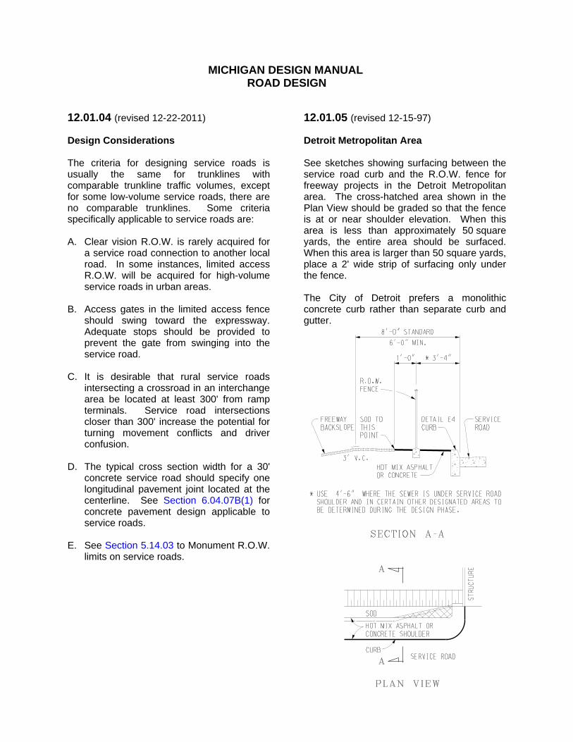
12.01.05 (revised 12-15-97) Detroit Metropolitan Area See sketches showing surfacing between the service road curb and the R.O.W. fence for freeway projects in the Detroit Metropolitan area. The cross-hatched area shown in the Plan View should be graded so that the fence is at or near shoulder elevation. When this area is less than approximately 50 square yards, the entire area should be surfaced. When this area is larger than 50 square yards, place a 2' wide strip of surfacing only under the fence. The City of Detroit prefers a monolithic concrete curb rather than separate curb and gutter.
MICHIGAN DESIGN MANUAL
ROAD DESIGN
12.02 LOCAL ROADS AND STREETS 12.02.01 (revised 3-21-2016) References A. Geometric Design Guide GEO-640 Series,
"Turned-in Roadways" B. Geometric Design Guide GEO-650 Series,
"Flares and Intersection Details" C. "Act 51, P.A. of 1951, As Amended, a Part
of Michigan Highway Law" D. A Policy on Geometric Design of
Highways and Streets, AASHTO, 2011 6th Edition
E. Standard Plan R-30-Series, “Concrete
Curb and Concrete Curb & Gutter” 12.02.02 (revised 12-15-97) General The design of local roads and streets, as with service roads (Section 12.01) and turnbacks (Section 12.03), should be compatible with the design standards of the local agency having jurisdiction. While some counties and cities have design standards equal to trunkline standards, others do not. Usually, a county's primary road standards will be higher than its secondary road standards. The agency's standards can be determined by direct contact or by checking with the Local Agencies Unit. The Local Agencies Unit maintains up-to-date maps of all counties, cities, and villages. In addition, it has individual maps showing all roads certified by the local agency as part of the basis for Michigan Transportation Fund distribution. The city and village maps are authoritative for determining corporate limits.
12.02.02 (continued) Whenever a portion of a local road must be reconstructed as part of a trunkline project, the Department does not assume temporary jurisdiction. It is therefore unnecessary to return jurisdiction on completion of the construction. (An exception is when a local road may be taken over as a temporary trunkline where freeway construction ends.) 12.02.03 (revised 12-15-97) Intersection Approaches Where a trunkline resurfacing project and a local road intersect, the Region/TSC Traffic and Safety Engineer will designate an Approach Treatment Detail I, II, or III, from Geometric Design Guide GEO-650 Series. Approach Treatment Detail I is a "minimum" treatment. It is intended for use only when it is requested by the Region/TSC (therefore it should not be set up initially on preliminary plans). It is applicable at an unimproved gravel road or a limited use sand trail. The paved apron is widened to one paver-width and is intended to reduce the incidence of gravel and sand tracking and washing onto the trunkline pavement. The Approach Treatment Detail II is a "minimum paved approach" and uses limited arcs without curb and gutter. Approach Treatment Detail II is intended for improved, maintained local roads where it is felt that Approach Treatment Detail III is not warranted. It should be noted that the 30' radius is designed for the wheel path of a single unit commercial vehicle. It fits a turning school bus if the bus encroaches beyond the crossroad centerline.

MICHIGAN DESIGN MANUAL
ROAD DESIGN
12.02.03 (continued) Intersection Approaches The Approach Treatment Detail III is generally used on federal aid primary and secondary roads that intersect a trunkline and includes arcs of Roll Curb & Gutter, Detail B, to help delineate the local road opening. See Standard Plan R-30-Series. When Approach Treatment Detail III is called for, use Curb & Gutter, Detail B1 for rigid approach road pavements, and Curb & Gutter, Detail B2 for flexible approach road pavements. See Standard Plan R-30-Series.
12.02.03 (continued) The local road names are to be shown:
l. On the title sheet map.
2. On the plan sheet just below the border, above the plan view of the intersection.

MICHIGAN DESIGN MANUAL
ROAD DESIGN
12.02.03 (continued) Intersection Approaches
MICHIGAN DESIGN MANUAL
ROAD DESIGN
12.02.04 (revised 12-15-97) City of Detroit The following guidelines should be considered applicable to city streets and service roads in the City of Detroit. A. Sodding Slopes should be sodded, not seeded. Use Class A or B Sod depending on side conditions; i.e., residences, commercial areas, etc. B. Grades The desirable minimum grade across bridges is 0.6%. Alley grades, between the curb and the sidewalk, may vary from 2% minimum to 12.5% (+) maximum. C. Temporary Roads Use 8" thick concrete pavement, nonreinforced, if the temporary road will carry more than minimal traffic. Temporary concrete barrier, guardrail or curb should be placed between the temporary road and a sidewalk. D. Sidewalks The standard sidewalk width is 6'-0". When utility poles are in sidewalk areas, the plans should include ½” expansion fiber for placing around the utility poles and, in addition, that the poles be centered in a 30" square of sidewalk also surrounded by ½” expansion fiber. E. Curb Returns The standard city curb radius is 20' at returns. The property corner should be a minimum of 10' from the face of the curb at returns.
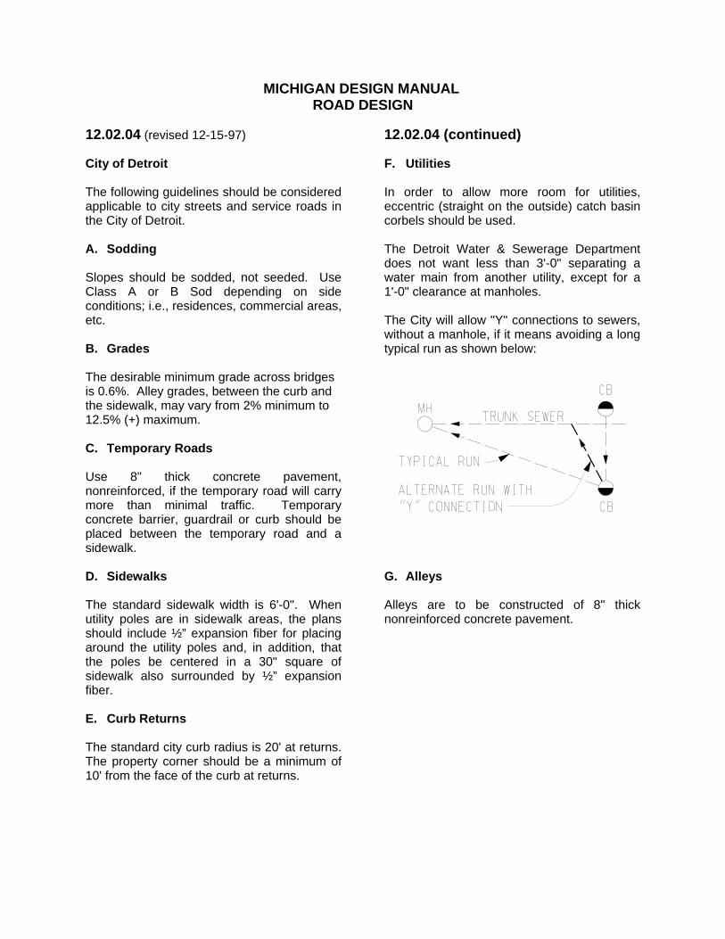
12.02.04 (continued) F. Utilities In order to allow more room for utilities, eccentric (straight on the outside) catch basin corbels should be used. The Detroit Water & Sewerage Department does not want less than 3'-0" separating a water main from another utility, except for a 1'-0" clearance at manholes. The City will allow "Y" connections to sewers, without a manhole, if it means avoiding a long typical run as shown below: G. Alleys Alleys are to be constructed of 8" thick nonreinforced concrete pavement.

MICHIGAN DESIGN MANUAL
ROAD DESIGN
12.02.04 (continued) City of Detroit H. SCANDI The acronym SCANDI is derived from "Surveillance, Control, and Information." The system, which is operational but not complete as envisioned, consists of wires and sensors buried in the freeway. Any project that involves a freeway in Detroit should be examined for its possible impact on the SCANDI system. Metro Region/TSC Traffic and Safety can advise Design as to whether or not the SCANDI system is involved in the proposed project limits. As part of a normal Region/TSC plan review, SCANDI personnel will participate, as appropriate. Whenever SCANDI facilities are affected by a proposed project, a special provision is required to warn the contractor of their responsibilities. This write-up is usually furnished by the Metro Region/TSC to ensure the latest information is provided. Additionally, the following note should be shown on plan sheets showing SCANDI facilities: Warning: The SCANDI project employs extensive cabling on Detroit freeways. The contractor will be held responsible for repair expenses. See General Plan Notes for notification procedure.
12.02.04H (continued) There is a companion "General Plan Note" entitled, "Underground Cables Warning." For general information, the SCANDI system currently involves the following Detroit freeway segments: 1. I-94 (Ford Freeway) from the west city
limits of Detroit to the northeast city limits 2. US-10 (Lodge) from 8 Mile Road to Cobo
Hall 3. I-75 (Chrysler) from Wilkins Street (just
north of I-94) south including I-375 4. I-75 from the Chrysler to the Jeffries

MICHIGAN DESIGN MANUAL
ROAD DESIGN
12.03 TURNBACKS 12.03.01 References A. Department Regulation 2520.02, "State
Trunkline Jurisdiction Transfer" B. Bureau of Highways Operating Instruction,
"Turnback Review Committee" C. Bureau of Highways Operating Instruction,
"Lump Sum Payment on Turnbacks" (see Section 12.03.04)
12.03.02 (revised 12-15-97) General When it is determined that a road presently under state jurisdiction does not serve the function of a trunkline, it is the policy of the Department to effect its transfer to local jurisdiction. Examples of such roads are short segments replaced by relocated new construction, short trunklines that should never have been trunklines by current definition, and longer trunklines that were replaced by freeways. Negotiations for turnbacks are handled by the Turnback Review Committee, which presently consists of representatives from the Design Division and the Region/TSC Engineer in the affected area. The Committee works under Act 296, P.A. of 1969, which provides that the road being turned back must be "relatively free of extraordinary maintenance for a period of 5 years" following turnback. This requirement forms the basis for negotiating the scope of the rehabilitation project. The law provides slightly different criteria for relocation turnbacks, as opposed to classification turnbacks, although the Department by policy treats both the same.
12.03.02 (continued) Service road jurisdiction is transferred the same as conventional turnbacks, except that the Turnback Review Committee does not usually become involved unless the Department has retained jurisdiction for a number of years with the result being the service road requires rehabilitation. 12.03.03 Turnback Letter When the Turnback Review Committee reaches agreement with the local agency regarding the scope of the rehabilitation project, a "Turnback Letter" is written to management setting forth the agreement details of the proposed project. When approved by management, this letter sets in motion the programming of the project and assignment in Design. While generally avoiding details, the Turnback Letter will contain certain details, notably thicknesses of hot mix asphalt (HMA) surfacing and pavement widths. These items will have been agreed to and should not be changed during design. As a general rule, designers should not violate any of the recommendations of the Turnback Letter. If circumstances arise that may indicate a revision is desirable, the Chairman of the Turnback Review Committee should be contacted for concurrence. Aside from these restrictions and the items mentioned under Sections 12.03.04 and 12.03.05, a turnback project will be handled the same as any other project in Design, including statutory funding participation by the local agency, when applicable. When assigned the design of a turnback project, the designer should review any correspondence in the files for helpful background information and useful design data. The files of the Turnback Review Committee Chairman will also occasionally prove to be a valuable source of information.

MICHIGAN DESIGN MANUAL
ROAD DESIGN
12.03.04 Lump Sum Payments Act 296 provides that a lump sum payment to the local agency is an alternative to a rehabilitation project. This is usually attractive to the local agency when it desires a major reconstruction, something more than the Department is bound by law to provide. The Bureau of Highways, Office Informational Memorandum (O.I.) "LUMP SUM PAYMENT ON TURNBACKS" will be used to determine the fair and equitable amount of a lump sum payment. The designer's responsibilities are outlined in the O.I. 12.03.05 Right-of-Way As a general policy, the Department will not acquire additional R.O.W. on turnbacks. If additional R.O.W. is required, it must be obtained by the local agency. There are a couple of exceptions to this rule, however: A. If in fact it develops that the Department
does not own all of the R.O.W. shown as "existing" in the R.O.W. map book, we may acquire, at project cost, that which we assumed was ours, but isn't.
B. Grading permits may be obtained at
project cost. Management has applied the restriction that grading permits must be approved by the Chairman of the Turnback Review Committee.
On completion of the turnback project and transfer of jurisdiction, any transferable interest in the R.O.W. will be conveyed by the Department. Title to excess R.O.W. will remain with the Department.
12.03.06 (revised 5-26-2015) Bicycle Facilities Bicycle facilities may be included on turnback projects if recommended by the Bureau of Transportation Planning Bicycle/Pedestrian Coordinator and provided the path does not itself require additional R.O.W. Generally the funding for these facilities would come from the Transportation Alternatives Program.

MICHIGAN DESIGN MANUAL
ROAD DESIGN
12.04 TEMPORARY ROADS 12.04.01 revised 12-22-2011) References Road Design Manual, Chapter 6 Section 6.03.16, "HMA Curb"
Section 6.04.07C, "Temporary Concrete Pavement" Geometric Design Guide GEO-690 Series "Temporary Runaround" 12.04.02 (revised 12-15-97) General The need for temporary roads and structures should be determined and programmed during project scoping when factors pertaining to maintaining traffic are discussed. Designers should also be alert to situations where a temporary road might be required. The need for a temporary road, along with its geometrics and cross section, should be reviewed and finalized with the Region/TSC during preliminary design. Numerous failures of temporary roads have occurred due to lack of attention to drainage and structural adequacy. A barely adequate road, reconstructed a second time and/or requiring continual maintenance, may cost as much or more than an initially higher class facility that was properly constructed. 12.04.03 (revised 12-15-97) Design Considerations The temporary road should be designed according to the designated design speed. Final plans should show alignment, grade, appurtenances and the proposed typical cross section of the temporary road. Any temporary right-of-ways should also be shown.
12.04.03 (continued) If the temporary road's usage is only for minor or local traffic needs during one construction season and if base soils are good, a minimum- type road will perhaps suffice. A minimum cross section would consist of 6" of granular subbase with an additional 6" of gravel (22'-0" wide), plus 4'-0" wide gravel or earth shoulders. A quantity of maintenance gravel should be provided, as well as a dust palliative (see Section 6.02.11B). Generally, if traffic volumes are substantial, an HMA or concrete pavement recommendation should be provided as part of the scoping. A paved surface may vary in design from a single-course HMA mat to 8" reinforced concrete. A 8" non-reinforced concrete pavement is common in the Detroit metropolitan area. Cross drainage must be accommodated by means of temporary culverts. Culvert end treatment may be omitted except in the case of flowing streams, where sandbags or bag riprap may be warranted in lieu of end sections. 12.04.04 (revised 12-22-2011 ) Removal of Temporary Roads and Structures Removal of a temporary road may be done by using either of the items, "Obliterate Old Road" or simply paying for it as "Excavation, Earth", as provided in the plans. The Construction Field Services Division seems to favor removal as Earth Excavation. If the surfacing material is more than 5" thick, the removal is usually paid for separately. Removal of temporary structures is included in the pay item: Structure, Temp, Rem (Structure No.).
MICHIGAN DESIGN MANUAL
ROAD DESIGN
12.05 DETOURS 12.05.01 Reference Department regulation 5200.01, "Maintaining Traffic in Construction Zones." 12.05.02 (revised 12-15-97) General The Department's definition of "detour" is the utilization of existing roads to carry trunkline traffic during construction. Lane closures, weekend shutdowns, or the use of a temporary road are not considered detours. The need for a detour must be considered and finalized during the scoping process so that the detour route can be reviewed during the preliminary design. If local roads are to be utilized, the local agency should be informed early by the Region/TSC of the Department's proposed use of its facility, and there should be agreement as to the extent and character of the route improvements or restoration that will be needed. When a detour is recommended, a public hearing may be required. Approval of the detour route by local officials does not always satisfy "public hearing requirements". The final detour should be submitted, as soon as possible, to the Public Involvement Section even though the Environmental Impact Statement may contain references to the detour. If a public hearing is required, the Public Involvement Section will take care of the details. Also, the Federal Highway Administration should be kept informed on non-exempt projects.
12.05.03 Design Considerations All aspects of the detour should be considered during the design stage. The detour quantities and the plans for detour signing should be included in the project plans. The detour route should be shown on the title sheet project location map with small directional arrows. (Formerly the route was labeled "possible detour," but the word "possible" should not be used because of its connotation of uncertainty as to where the detour route will be located.) If the detour is along local roads and the existing facility is adequate to handle the diverted trunkline traffic, the local agency will often agree to rehabilitation after the detour is taken out of use. This is preferable to upgrading the detour before use because it enables an accurate assessment, after project construction, as to what repairs are needed. The local agency also has the advantage of a renovated facility rather than one that has suffered the wear and tear of detour traffic. An important consideration when comparing the merits of a detour versus a temporary road is the residual value of any improvements made to the detour. 12.05.04 (revised 12-15-97) Federal Participation Federal participation is available on federal-aid projects for construction, reconstruction, restoration, pavement marking, and signing of detours. It is essential, however, that such work be programmed and the cost estimate submitted at the time of scoping as part of the total project package. The FHWA must be afforded the opportunity of a plans-in-hand inspection on non-exempt projects.
MICHIGAN DESIGN MANUAL
ROAD DESIGN
12.06 HAUL AND ACCESS ROADS 12.06.01 (revised 12-15-97) Department Involvement There are three principal reasons for the Department becoming involved in haul and access roads: A. The Department furnishes the borrow area
and designates the haul route. In this case, the Department will also obtain the necessary R.O.W. or grading permit.
B. The haul route uses Department
designated local roads and the contract may include quantities of gravel, dust palliative, etc., for maintenance and quantities for restoration. Restoration would be handled similar to that of a detour (see Section 12.05.03).
C. The local unit of government is paid on a
force account basis to maintain and restore designated access roads located between an existing trunkline and a new roadway under construction. (Usually the access roads are to carry the contractor's materials and overloaded equipment)
The costs for maintenance and restoration of a Department haul or access road are eligible for federal participation, when the roads are included in the programming and a plans-in-hand inspection is held. When a haul route crosses a railroad and is the responsibility of the Department, the Department will contact the railroad to make the necessary crossing arrangements. The project should include a special provision for the pay item "Railroad Crossing, Temporary" (each). However, the Department prefers the haul route be the responsibility of the contractor, making the contractor responsible for making the arrangements with the railroad.
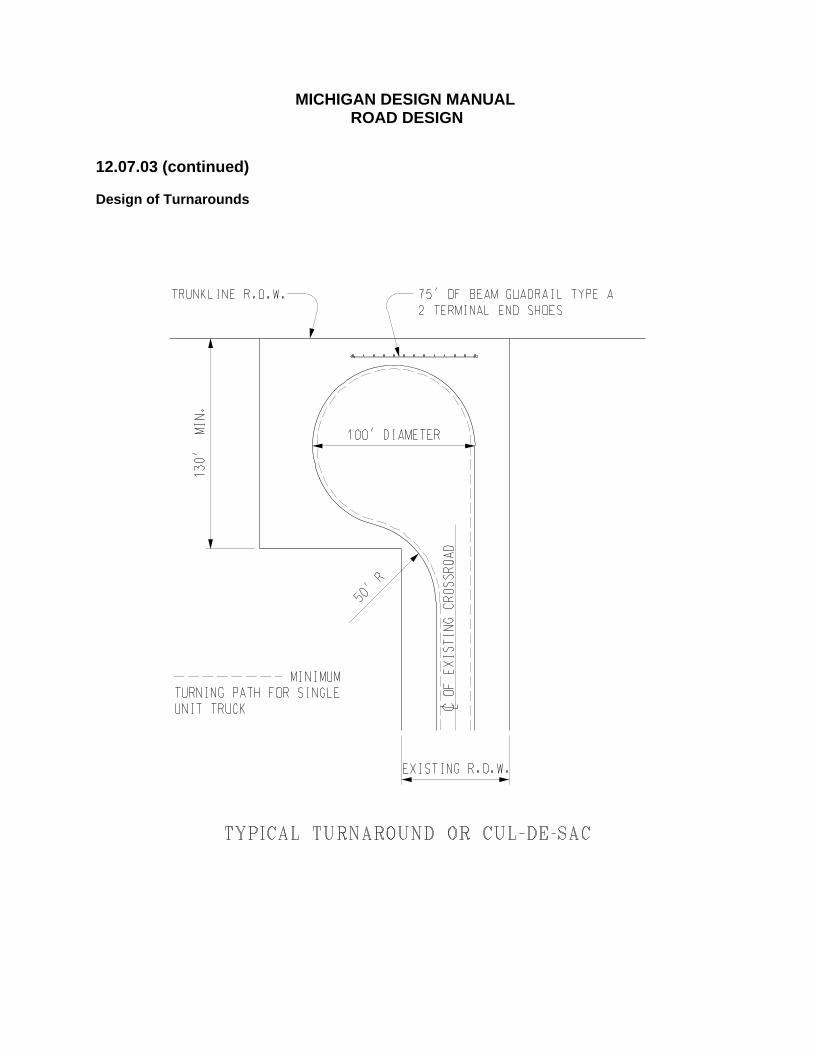
12.07 TURNAROUNDS AND CUL-DE-SACS 12.07.01 Definitions The Department's use of the terms "cul-de-sac" and "turnaround" are similar in that they describe a treatment at the end of a dead end road, that will enable a vehicle to turn around and exit from the dead end road. A cul-de-sac allows a vehicle to circle and return without reversing. While turnarounds can be circular, they can also be a "turn-in, back-out" T-shaped configuration. 12.07.02 (revised 12-15-97) Location Turnarounds are constructed on the ends of a local road that has been severed by a limited access roadway. This happens when the local road does not warrant a grade separation. The turnaround treatment will be shown in the Engineering Report and is approved by the local agency during the Early Preliminary Engineering stage. 12.07.03 (revised 12-15-97) Design of Turnarounds The design of a typical turnaround is illustrated on the next page. By offsetting the turnaround to one side of the local road, only one steering reversal is required and additional R.O.W. need only be obtained from one side of the road. The turnaround may be centered on the local road if R.O.W. is tight on both sides, but this is the least preferable of the two alternatives. Turnarounds in urban areas may be of special design as requested by the local agency. An example might include a curbed island in the center, with 27' wide roadways. This would discourage using the turnaround as a playground.
MICHIGAN DESIGN MANUAL
ROAD DESIGN
12.07.03 (continued) Design of Turnarounds
MICHIGAN DESIGN MANUAL
ROAD DESIGN
12.08 DRIVEWAYS 12.08.01 (revised 7-10-2006) References A. "Administrative Rules Regulating
Driveways, Banners and Parades On and Over Highways" Effective November 20, 1998, and based on Act 200, P.A. of 1969. Published by Utilities Coordination & Permits Section.
B. Standard Plan R-29-Series, "Driveway Openings, Driveways and
Concrete Sidewalks." C. Standard Plan R-95-Series, "Culvert Sloped End Sections" D. Geometric Design Guide GEO-680 Series 12.08.02 (revised 12-15-97) General Through the issuance of permits, the Department controls the construction and alteration of private drives that open onto state trunklines. These permits refer to and are based on the Administrative Rules (Reference A, above). All costs for these drives are the responsibility of the abutting property owner. When road construction affects a drive, the cost of the required work becomes the responsibility of the Department. The Administrative Rules are quite specific with respect to geometry and surface thickness. The designer can sometimes deviate from the rules regarding surface thickness and should see Administrative Rule 23, to be certain the Rules allow the deviation. The location and geometrics of any affected driveways should be coordinated with the Region/TSC Traffic and Safety Engineer. The Designer also needs to review any unique drives (high fills, etc.) with the Geometrics Unit.
12.08.03 (revised 11-21-2016) Urban Drives A. Location - R.O.W. Encroachment In urban areas where narrow building lots may prevail, driveways may need to be located close to the property line. Administrative Rule 31, provides that the driveway approach including the radii shall be located entirely within the area between the owner's property lines extended to the street centerline. A driveway radius may extend outside this area only if the adjacent property owner certifies in writing that they will permit such extension. This permission is obtained by the Development Services Division at the time of negotiation for driveway permits with the affected property owners. B. Extent of Surfacing When it becomes necessary to alter drives on urban road projects, it is the Department's policy to provide hard surfacing adjacent to the traveled roadway. This is done to avoid the washing of stones and dirt onto the pavement. See rules 51 & 52, of Administrative Rules. The limits of residential driveway surfacing will usually be determined during preliminary design. Paving should extend at least 10' from the edge of pavement. If a few additional feet of surfacing is needed to meet an existing or imminently proposed sidewalk, the surfacing between the curb and the sidewalk should be completed. Existing surfacing on commercial drives will usually have to be replaced to the extent that it is disrupted by road construction.
MICHIGAN DESIGN MANUAL
ROAD DESIGN
12.08.03 (continued) Urban Drives C. End Treatment When upgrading the ends of urban driveway culverts see MDOT Drainage Manual Section 5.3.5 and Table 5-1. D. Surface Type Residential driveways will normally be surfaced to match the existing surfacing type, i.e., HMA if the existing is either HMA or gravel, and concrete if the existing drive is concrete. The type of surfacing at commercial drives is dependent upon the existing surfacing, the potential weight of vehicles using the drive, and the availability of paving material on the project. If concrete paving is the principle item used, then concrete should probably be used. If HMA paving is the item used, then HMA base course and top course would probably be more economical. The type of paving material to use on commercial drives will generally be determined at scope verification. E. Surface Thickness 1. The designer should use the following
guidelines for concrete drives.
Residential Drives
* Between curb and sidewalk (sidewalk
same thickness
6" or thicker if locally required
* Back of sidewalk
5" or match existing thickness
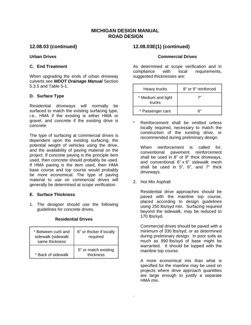
12.08.03E(1) (continued)
Commercial Drives
As determined at scope verification and in compliance with local requirements, suggested thicknesses are:
Heavy trucks 8" or 9" reinforced
* Medium and light trucks
7"
* Passenger cars 6" * Reinforcement shall be omitted unless
locally required, necessary to match the construction of the existing drive, or recommended during preliminary design.
When reinforcement is called for,
conventional pavement reinforcement shall be used in 8" or 9" thick driveways, and conventional 6" x 6" sidewalk mesh shall be used in 5", 6", and 7" thick driveways.
2. Hot Mix Asphalt
Residential drive approaches should be paved with the mainline top course, placed according to design guidelines using 250 lbs/syd min. Surfacing required beyond the sidewalk, may be reduced to 170 lbs/syd.
Commercial drives should be paved with a minimum of 330 lbs/syd, or as determined during preliminary design. In poor soils as much as 990 lbs/syd of base might be warranted. It should be topped with the mainline top course. A more economical mix than what is specified for the mainline may be used on projects where drive approach quantities are large enough to justify a separate HMA mix.
.
MICHIGAN DESIGN MANUAL
ROAD DESIGN
12.08.03 (continued) Urban Drives F. Curb See Rules 51 and 52, of the Administrative Rules. Curbing should be as provided in the rules or as modified during preliminary design. G. Curb Openings
Drives Concrete Driveway Opening,
Residential Detail L
Commercial Detail M (Note that drive opening Detail M is a pay item, whereas Detail L is not.) See Section 6.06.19 for Driveway Openings. H. Associated Tapers and Deceleration Lanes Deceleration lanes and tapers at drives should generally be the same material and same thickness as the drive. Where an auxiliary lane or taper could be used as a driving lane, as might occur in the vicinity of multiple drives to a large shopping center, the auxiliary paving should match the type and thickness of the adjacent roadway lane. I. Grades Maximum driveway slopes are shown on Standard Plan R-29-Series. The combination of maximum change in slopes should be checked particularly when the sidewalk is close to the curb, the street is in superelevation sloping toward the drive, or the street crown is severe. If a combination of changes in slope is adequate for a large car, it follows that it will probably be adequate for a smaller car, which usually has a shorter overhang.
12.08.04 (revised 7-10-2006) Rural Drives A. Grading Drives On free access projects involving heavy grading, the location or relocation of drives is an important function of the design process. A major grade change can easily create an impossible or unacceptable drive situation necessitating a relocation. The designer may have his or her ingenuity tested in an attempt to avoid steep grades and circuitous routes while aligning the drive with the property owner's garage or parking area. The property owner should be advised to the advantages and disadvantages of the various alternatives. Since the property owner is the one having to live with the resulting conditions, their preference should be adhered to, provided it is within the bounds of sound engineering. Whenever grading for a drive must be done beyond the R.O.W. line, a grading permit must be obtained. If possible, 8 seconds of sight distance onto the roadway should be provided for vehicles exiting a drive. (The 8-second distance should be based on the posted speed of the roadway.)

MICHIGAN DESIGN MANUAL
ROAD DESIGN
12.08.04 (continued) Rural Drives B. Surfacing Residential drives and field drives are often surfaced with an Aggregate Surface Course, 4" thick. When the drive grade ascends or descends from the roadway at a gradient steeper than 5%, the drive should be HMA surfaced at the rate of 170 lbs/syd for the length of the regrading. This practice, which is applicable to reconstruction projects only (not to resurfacing projects that do not normally involve regrading), controls washouts and the depositing of sand and topsoil on the road shoulder. It also aids in negotiating with a property owner who is faced with the prospect of a steeper drive.
12.08.04 (continued) C. Driveway Fill Slopes Driveway slopes should be traversable (1:6 or flatter) to minimize the hazard to an out of control vehicle straying from the highway (see sketch below). Note that while both side slopes should be traversable on two-way roadways, it is only necessary that the approach side have traversable slopes when the drive is on a dual highway. See Rule 61, of the "Administrative Rules Regulating Driveways, Banners, and Parades on and over Highways", November 20, 1998.

MICHIGAN DESIGN MANUAL
ROAD DESIGN
12.08.04 (continued) Rural Drives D. Driveway Culverts 1. Minimum size
South of M-46 12"
North of M-46 in lower peninsula
15"
Upper peninsula 18"
The rationale for larger-size minimum culverts in the northern part of the state is based upon the potential for a greater ice build up and from a greater runoff of spring rains caused by the ground being frozen.
2. Cresting Drives
Driveway culverts can often be eliminated by placing the drive at the crest and by using independent ditch grades. This practice is acceptable, but should not be carried to extremes.
3. End Treatment See MDOT Drainage Manual Section
5.3.5 and Table 5-1.

MICHIGAN DESIGN MANUAL
ROAD DESIGN
12.09 CROSSOVERS 12.09.01 References Geometric Design Guide GEO-670 Series 12.09.02 (revised 12-22-2011) General Permanent crossovers are of two types: the emergency and maintenance crossover, commonly associated with limited access roadways and the periodic local traffic crossover that is a necessary adjunct to free access divided roadways. In urban areas, the designer should coordinate crossover locations with the Region/TSC Traffic and Safety Engineer, the local community, and/or the county road agency. The final location of crossovers needs to be coordinated with the Design Division’s Geometrics Unit. 12.09.03 (revised 12-22-2011) Free Access Divided Highways On the premise that an extra travel distance of up to 1/4 mile is not excessive when crossing a free access divided highway, the following criteria for crossover spacing should apply: A. Medians Less Than 30' in Width Crossovers may be constructed, as determined by the Design Division’s Geometrics Unit, opposite driveways and side roads or streets. B. Medians 30' or More in Width Crossovers may be provided every 1/8 mile (660') in urban areas and every 1/4 mile in rural areas. They may be adjusted 100' either way to conform to existing street or road returns or driveways. No two crossovers should be closer than 500' apart. Public roads should take priority over private drives in the event of a location conflict.
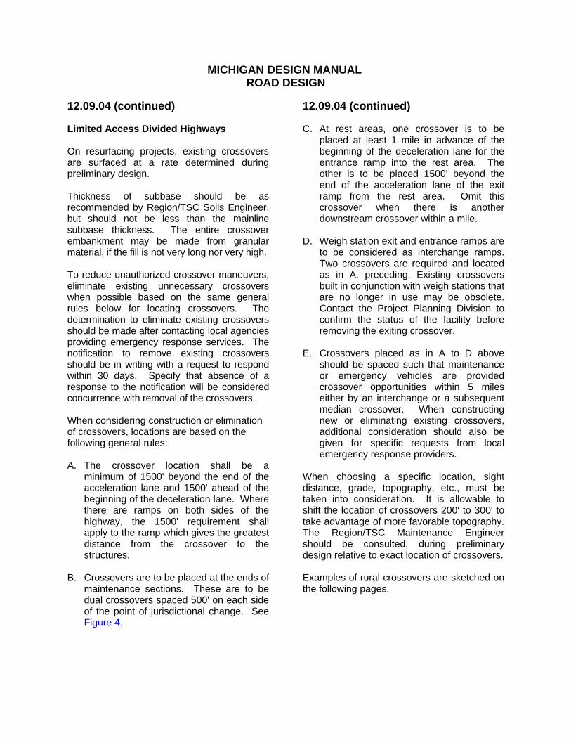
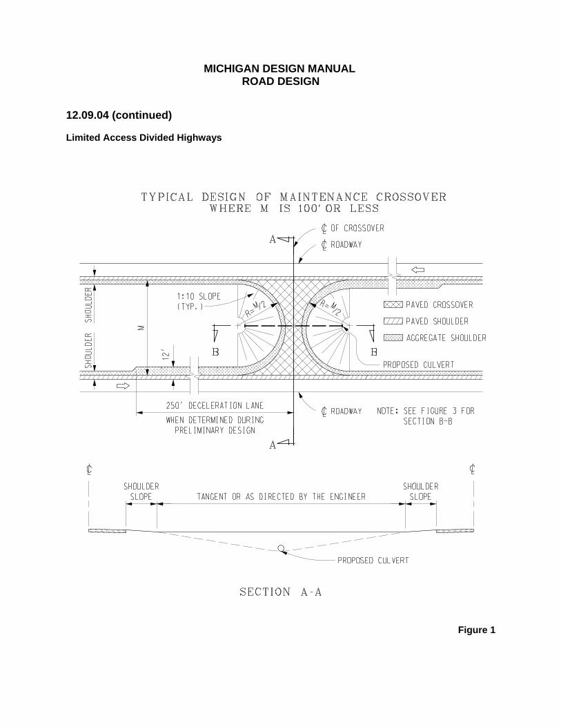
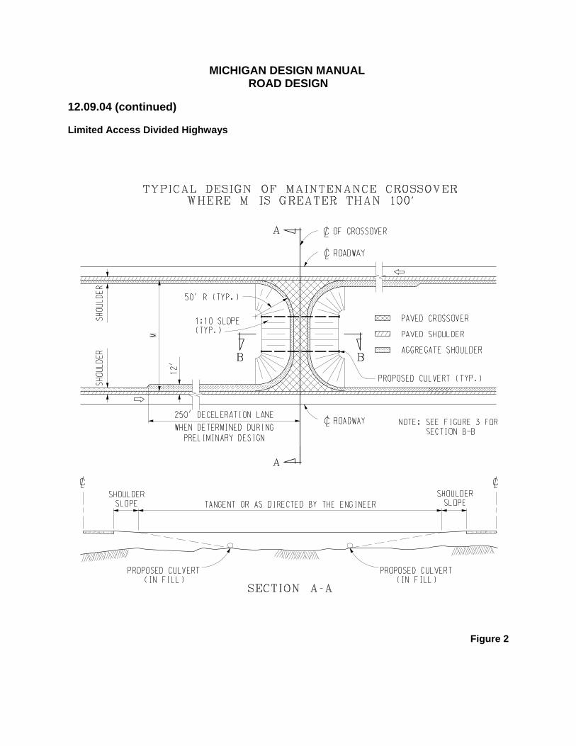
12.09.03B (continued) Crossovers for through cross streets may be closer than 500' apart. Additional crossovers may be provided for large developments, e.g., shopping centers, as approved by the Design Division’s Geometrics Unit. If constructed on an existing road, the cost of a new crossover should be borne by the adjacent property owner or developer requesting the crossover, unless the original road construction failed to provide the theoretical 660' spacing. It is desirable that medians over 30' in width be constructed to physically prohibit random crossing of the median. This can be done with either a ditch or a barrier. 12.09.04 (revised 3-24-2011) Limited Access Divided Highways Crossovers on limited access divided highways are for the use of maintenance, police, and emergency vehicles. It is illegal for the public to use them. To discourage such unauthorized use it was Department practice, until May 1985, to simply gravel surface crossovers to make them as unobtrusive as possible. This led to increased maintenance and it became debatable whether it discouraged unauthorized use by a motorist that was determined on making a U-turn. The Engineering Operations Committee (E.O.C.) decided that rural maintenance crossovers will be paved. These crossovers are to have 3" thick HMA surfaces, laid on 8" of Aggregate Base - HMA 1.5' wider on each side than the HMA mat. While an application rate of 330 lbs/syd is usually associated with a 3" thickness, consideration should be given to using the application rate of the top two courses of mainline HMA surfacing, even if the combined rate is 290 lbs/syd and only approximates 3".
MICHIGAN DESIGN MANUAL
ROAD DESIGN
12.09.04 (continued) Limited Access Divided Highways On resurfacing projects, existing crossovers are surfaced at a rate determined during preliminary design. Thickness of subbase should be as recommended by Region/TSC Soils Engineer, but should not be less than the mainline subbase thickness. The entire crossover embankment may be made from granular material, if the fill is not very long nor very high. To reduce unauthorized crossover maneuvers, eliminate existing unnecessary crossovers when possible based on the same general rules below for locating crossovers. The determination to eliminate existing crossovers should be made after contacting local agencies providing emergency response services. The notification to remove existing crossovers should be in writing with a request to respond within 30 days. Specify that absence of a response to the notification will be considered concurrence with removal of the crossovers. When considering construction or elimination of crossovers, locations are based on the following general rules: A. The crossover location shall be a
minimum of 1500' beyond the end of the acceleration lane and 1500' ahead of the beginning of the deceleration lane. Where there are ramps on both sides of the highway, the 1500' requirement shall apply to the ramp which gives the greatest distance from the crossover to the structures.
B. Crossovers are to be placed at the ends of
maintenance sections. These are to be dual crossovers spaced 500' on each side of the point of jurisdictional change. See Figure 4.
12.09.04 (continued) C. At rest areas, one crossover is to be
placed at least 1 mile in advance of the beginning of the deceleration lane for the entrance ramp into the rest area. The other is to be placed 1500' beyond the end of the acceleration lane of the exit ramp from the rest area. Omit this crossover when there is another downstream crossover within a mile.
D. Weigh station exit and entrance ramps are
to be considered as interchange ramps. Two crossovers are required and located as in A. preceding. Existing crossovers built in conjunction with weigh stations that are no longer in use may be obsolete. Contact the Project Planning Division to confirm the status of the facility before removing the exiting crossover.
E. Crossovers placed as in A to D above
should be spaced such that maintenance or emergency vehicles are provided crossover opportunities within 5 miles either by an interchange or a subsequent median crossover. When constructing new or eliminating existing crossovers, additional consideration should also be given for specific requests from local emergency response providers.
When choosing a specific location, sight distance, grade, topography, etc., must be taken into consideration. It is allowable to shift the location of crossovers 200' to 300' to take advantage of more favorable topography. The Region/TSC Maintenance Engineer should be consulted, during preliminary design relative to exact location of crossovers. Examples of rural crossovers are sketched on the following pages.
MICHIGAN DESIGN MANUAL
ROAD DESIGN
12.09.04 (continued) Limited Access Divided Highways
Figure 1
MICHIGAN DESIGN MANUAL
ROAD DESIGN
12.09.04 (continued) Limited Access Divided Highways
Figure 2
MICHIGAN DESIGN MANUAL
ROAD DESIGN
12.09.04 (continued) Limited Access Divided Highways
Figure 3

MICHIGAN DESIGN MANUAL
ROAD DESIGN
12.09.04 (continued) Limited Access Divided Highways
Figure 4

MICHIGAN DESIGN MANUAL
ROAD DESIGN
12.09.04 (continued) Limited Access Divided Highways
Figure 5
MICHIGAN DESIGN MANUAL
ROAD DESIGN
12.10 REST AREAS AND WEIGH STATIONS 12.10.01 (revised 11-19-2009) References A. Geometric Design Guide GEO-500 Series
"Rest Area" 12.10.02 (revised 11-19-2009) General The location, building design, and layout of rest areas are the responsibility of Region/TCS and the Roadside Development Unit. The latter does the horizontal and vertical design, including grading contours and sidewalk layout, and coordinates the lighting, water supply, and sewage disposal design. The Designer has the responsibility of performing engineering calculations and assembling and completing the project plans and specifications. Obviously, there must be close coordination between the Designer and the Roadside Development Unit.
12.10.02 (continued) Operation of truck weigh stations is under the Department of State Police. MDOT is responsible for the infrastructure including ramps, static scales, electronic weighing sensors in the pavement, parking lots, signing and the building structures. The Department of Transportation's weigh station activities are centralized under a Commercial Vehicle Strategy Team (CVST). There are two basic types of weigh stations: those that require the truck to be stationary during weighing and the more sophisticated type that is capable of weighing the vehicle while it is in motion. The Designer has the principal responsibility for layout of the weigh station area, initiating and coordinating utility and building design, performing engineering calculations with respect to ramps and parking areas, and coordinating all of the plans and specifications into a project. As with rest areas, the Design Utility Units will provide lighting, water, and sewage disposal plans. The designer must place heavy reliance on the CVST. 12.10.03 (revised 12-15-97) Location With Respect to Interchanges If possible, rest areas and weigh stations should be located such that there will be a minimum of 3000', and preferably more than 4000', between the gores of the ramps to an interchange and the rest area or weigh station.
MICHIGAN DESIGN MANUAL
ROAD DESIGN
12.10.04 Selection of Pavement Type in Rest Areas The Engineering Operations Committee has decided (April 3, 1985) that no standard for paving rest areas should be adopted. Rather, each individual location should have a case by case determination of pavement type depending on the density of both passenger and commercial traffic, the character of the soils, and other cost considerations. Concrete and HMA surfaces are considered as equals, in terms of service, so local conditions and the cost analysis will determine the type of pavement to be used. 12.10.05 Curb Type in Rest Areas Curb and Gutter, Detail C, which has a 7" curb face, will normally be used in rest areas.
12.10.06 Pending 12.10.07 (revised 12-15-97) Barrier in Advance of Weigh Station Building To protect the occupants of the building, 120' of reinforced concrete barrier should be constructed in advance of the building, flared from the ramp roadway on a 1:15 taper.
MICHIGAN DESIGN MANUAL
ROAD DESIGN
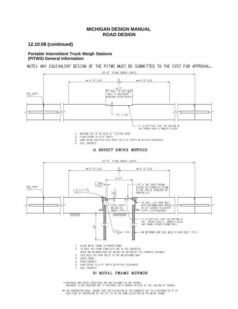
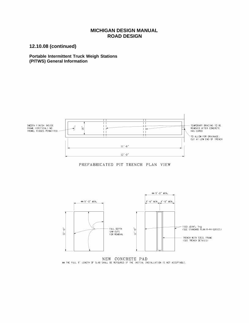
12.10.08 (revised 8-20-2012) Portable Intermittent Truck Weigh Stations (PITWS) General Information SITE SELECTION In considering the safety of officers and
passing motorists, the desired order of preference for new PITWS locations is in a rest area, a recognized Safe Enforcement Site, MDOT and county garages, carpool parking lots.
PITWS will not be permitted on a freeway shoulder. Due to traffic volume, PITWS will not be installed in the shoulder of any road unless supported by a low ADT, or installed in a recognized Safe Enforcement Site.
PITWS will not be permitted in the mainline.
The finished site must allow a minimum 3’ safe working area on all sides of a target vehicle. This area must be a reasonable grade and levelness, allowing the officer to operate safely around the target vehicle with a 12’ work area on the vehicle travel side.
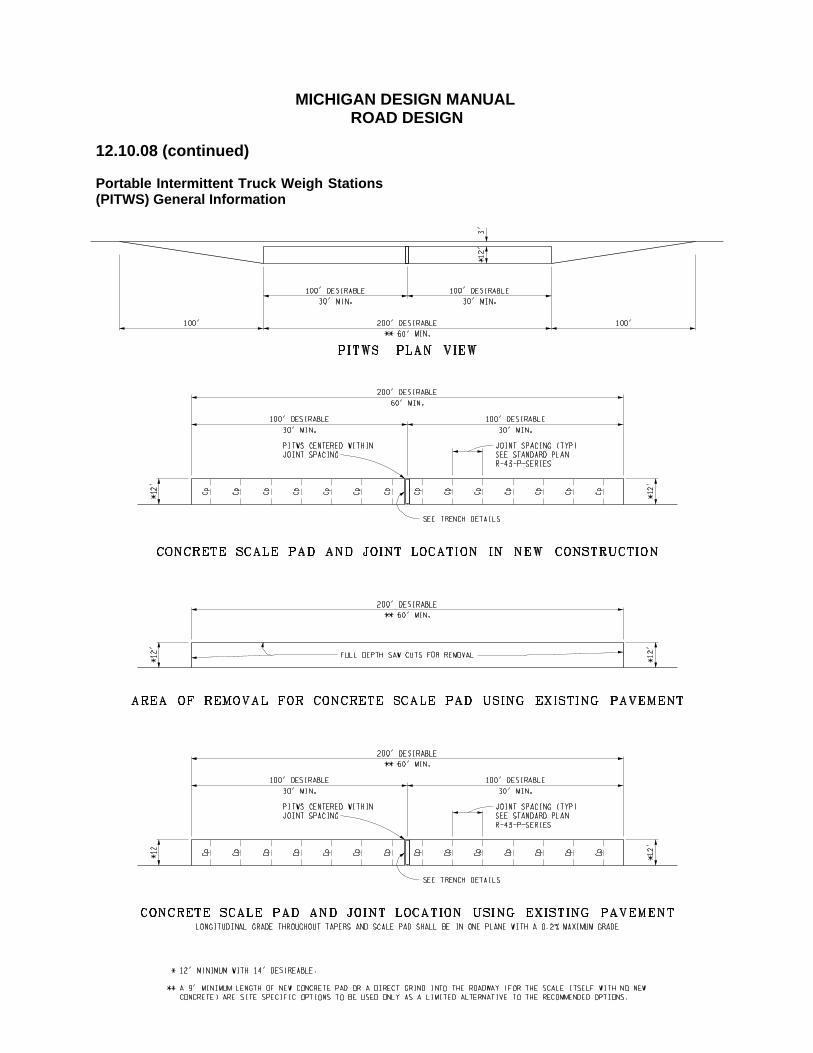
Concrete pads less than 200’ shall not be installed in asphalt. However, concrete pads of at least 60’ may be installed into asphalt with a concrete base with proper anchoring into the existing concrete base.
GENERAL REQUIREMENTS PITWS LOCATION: In all cases, the PITWS shall be centered
within the joint spacing.
LANE WIDTH: A minimum of 12’, with 14’ being desirable
not including work area. See SITE SELECTION.
LANE LENGTH: The desirable length of straight pavement
is 200’ (100’ on either side of the PITWS), not including approach and departure tapers, with a minimum length of 60’ (30’ on either side of the PITWS).
12.10.08 (continued) PAVEMENT COMPOSITE & THICKNESS: It is recommended that the area meet or
exceed the thickness and composite specifications of the existing pavement slab.
New slabs, not proximate to any pavement, shall be designed consistent with the current full depth mainline concrete pavement standards.
CONCRETE REINFORCEMENT: Reinforcement is not required or
recommended, except at concrete joints, particularly in the center slab where the cut out will be located.
Concrete anchoring between poured slabs is REQUIRED on all new concrete, and between new concrete and existing concrete. All cut locations must be projected prior to pour so that proper reinforcement can be installed.
TAPER(S): Adequate tapers must be provided, before
and after the desired 200’ of straight pavement, to allow the vehicle to remain straight while on the pad. Vehicles approaching and/or leaving the 200’ pad in a straight-line need no taper(s).
Generally, 100’ of taper into the straight approach pad and 100’ of departure taper beyond the departure pad is recommended.
LEVELNESS: A concrete scale pad shall not be placed
in a vertical curve section. The desired area 100’ on both sides of the scale trench shall be preferably in one plane and within the specified grades.

MICHIGAN DESIGN MANUAL
ROAD DESIGN
12.10.08 (continued) Portable Intermittent Truck Weigh Stations (PITWS) General Information GRADE: Lateral - A zero grade is desirable, with a
maximum of 5%. Longitudinal – For newly placed slabs, as
close to a flat grade as possible is recommended to maintain stationary vehicles without brakes being applied, up to a maximum of .20%. For existing slabs a maximum of .20% is recommended.
CONDITION: All pavements, new and existing, must be
free of cracks, bumps or dips that may cause distinct elevation changes.
SMOOTHNESS Pavement surface must be level within
± 1/16” from center of slab to 30’ in either direction. The remainder of the pavement (excluding tapers) must be within ± 3/16”.
Pavement surface should receive a light broom finish. Tining is not recommended.
PAVEMENT REMOVAL (if applicable): Pavement removal, replacement,
reinforcement, and tied joint, when specified shall meet current MDOT design specifications, unless otherwise noted.
Regardless of depth, all pavement removal will be included in the pay item “Pavt, Rem”.
Standard pay items should be used for payment, however modification may be required in order to meet the requirements of this section.
12.10.08 (continued) PITWS Inspection: Contact CVST for inspection of PITWS.
MICHIGAN DESIGN MANUAL
ROAD DESIGN
12.10.08 (continued) Portable Intermittent Truck Weigh Stations (PITWS) General Information
MICHIGAN DESIGN MANUAL
ROAD DESIGN
12.10.08 (continued) Portable Intermittent Truck Weigh Stations (PITWS) General Information
MICHIGAN DESIGN MANUAL
ROAD DESIGN
12.10.08 (continued) Portable Intermittent Truck Weigh Stations (PITWS) General Information
MICHIGAN DESIGN MANUAL
ROAD DESIGN
12.11 RAILROAD CROSSINGS 12.11.01 References A. Standard Plan R-121-Series, "Track
Crossings" B. Standard Plan R-122-Series, "Railroad
Crossing Signals" C. Department Policy and Procedures
4110.02, "Coordination With Railroads" D. Michigan Manual of Uniform Traffic
Control Devices, Part VIII E. American Railway Engineering
Association, Manual for Railway Engineering
F. Association of American Railroads, Signal
Manual 12.11.02 (revised 9-17-2012) General By law, highway crossings of a railroad are the railroad's responsibility. If a highway improvement requires the elevation of the tracks to be raised more than 1", the highway agency must assume the cost of the track adjustment. If a highway is widened, necessitating lengthening of the crossing, cost of the additional crossing may be borne by the railroad. Changes in, or additions to, railroad signals are funded equally between the railroad and the Department. Existing agreements may dictate the cost responsibilities at particular crossings. Certain safety improvements at railroad crossings may be funded with federal or state grade crossing account funds. Also federal funds may be used for crossing improvements required in connection with road improvement projects. The Railroad Coordination Unit – Office of Rail should be consulted about laws, agreements and funding.
12.11.03 (revised 9-17-2012) Railroad Contacts When a railroad is involved on a Department project, the contact and negotiations with the railroad company are made by the Railroad Coordination Unit – Office of Rail. The designer should contact this unit very early in the design stage to alert the Railroad Coordination Engineer that a crossing is involved and to afford the opportunity for early project input. The Railroad Coordination Unit – Office of Rail may participate in the field reviews and may even request the railroad to attend. The field review party should make observations regarding crossing condition and compatibility with the proposed project, but it is the responsibility of the Railroad Coordination Unit – Office of Rail to determine the actual work required at the crossing. When railroad crossing improvements are federally funded, but the road work is with Michigan funds, the cost of detour traffic signing for the railroad crossing improvement should be included in the federally funded project. Any changes in the railroad facilities, including rail elevations, superelevation, or relocation, should be discussed with the Railroad Coordination Engineer and must have railroad approval. The Railroad Coordination Unit – Office of Rail will request prints from the designer, as necessary, to obtain approvals and agreements with the railroad.

MICHIGAN DESIGN MANUAL
ROAD DESIGN
12.11.04 (revised 9-17-2012) Design of At-Grade Crossings A. Track Elevations on Plans The existing track profile(s) should be shown on the road plans extending 1000' each side from the crossing, if possible. Occasionally track profiles are not available. If track adjustments in excess of 1" are required, track elevations should be requested. B. Track Raises Existing track elevations usually must be met at grade. Studying the top of rail profile will frequently disclose that a raise in track elevations may be as beneficial to the railroad as to the highway. Small raises in track elevation can be made at no large expense, but this is not true when tracks are lowered. Railroads almost never lower their tracks, but are usually cooperative when a small raise is considered. On those projects involving a track raise of any consequence (in excess of 1"), both the existing track profile and the new track profile through the crossing should be shown. In the case of new grade crossings, the existing track profile should be shown whether a track raise is required or not. This information is usually required by the various railroads for review when determining the need for adjusting the track profiles with respect to their own requirements. C. Establishing Grade The highway grade should be established to pass through the plane of the rails and at an elevation that is equal to the highest elevation of the two rails. See the details on Standard Plan R-121-Series, when establishing the highway grade to meet an at grade railroad crossing.
12.11.04C (continued) A very good study can be made of the crossing by plotting profiles and cross sections to a scale of 1:125 horizontal and 1:12.5 vertical. A profile should be plotted for the centerline and each edge of a 2-lane pavement and in addition, along each joint line or lane line for pavements more than 2 lanes in width. The location, top of rail elevations, and cross surface should be carefully shown on each profile. Show adjusted profiles to meet the edge of crossing by means of irregular or French curves. Distances of approximately 100' should be used on both sides of the crossing to warp the grade from the edge of crossing surface to the grade established through the top of rail plane. Avoid "humping" the grade any more than necessary. After profiles have been established, plot cross sections at frequent intervals so that the amount of warp and maximum crown may be visually assessed for the entire irregular section. After the sections are plotted, an adjustment in the profiles, other than the centerline profile, will usually have to be made to avoid an excessively tilted pavement. If the proposed pavement is only 2 lanes in width, it is necessary to warp out the of crown at the outer edges of the pavement, which is easily accomplished. The crown on multiple-lane pavements vary from 4" to 6", and unless the warping transition is of considerable length, the riding qualities of the outer lanes will not be good at high speeds. One point that is not always given sufficient consideration in discussing the riding qualities of a railroad crossing is that of speed. Crossings that ride well at slow speed to moderate speeds may ride badly at high speeds and vice versa. Crossings of multi-lane highways, especially if relatively long due to a skew, should be designed so that a minimum longitudinal grade is called for on the rails. Drainage is an important consideration in selection of grades because it directly affects crossing stability. Runoff should be intercepted where possible to prevent drainage into the crossing area.
MICHIGAN DESIGN MANUAL
ROAD DESIGN
12.11.04 (continued) Design of At-Grade Crossings D. Superelevation Where crossings are complicated by inclined grades on both the railroad and highway, by skew crossings, by multiple tracks, and/or by railroad superelevation in a plane opposite to that of the highway grade, a difficult problem results that usually cannot be completely and satisfactorily resolved. In establishing preliminary grades to eliminate or reduce existing track superelevation, the grade should always be laid to meet the high edge of the crossing, knowing that it will be necessary to request a raise in elevation. The Railroad Coordination Unit – Office of Rail can explore superelevation changes with the railroad. Main line track superelevation normally must be maintained, but the superelevation on switch tracks and side tracks can sometimes be reduced or eliminated entirely. Where the plane of superelevation of the tracks is counter to that of the highway grade, it is necessary to establish a short grade tangent to the top of both rails. At the intersections of this short tangent with the longer approaching grades, short vertical curves are used. If this treatment results in an undesirable "hump" it can be minimized somewhat by careful adjustment of the tangent intersections and the skillful choice of vertical curves. Sometimes the use of vertical curves with unequal tangents will make a much smoother crossing (i.e. detail grades).
12.11.04 (continued) E. Types of Crossings Three principal types of crossings are now used: hot mix asphalt with guard log or three rail, the prefabricated sectional treated timber crossing and the proprietary crossing surfaces. The proprietary crossing surfaces are generally considered to be superior, but their price is also greater. The selection of the type of crossing material will be as agreed upon between the Railroad Coordination Unit – Office of Rail and the Railroad. F. Railroad Owned Materials Occasionally the plans will call for the contractor to remove railroad owned materials, principally rails, fittings, and ties, during the progress of the work. In most cases the railroad company wants these materials salvaged for its future use. Ordinarily the disposition of such material will be covered in an agreement or by letter communication with the Department. The proposed disposition of such material should be indicated on the plans so the contractor will not assume that the salvaged material is to become the contractor's property. When the disposal becomes the responsibility of the contractor, railroad ballast, railroad ties, treated wooden piles and treated wood posts disposition shall be as follows: 1. Railroad Ballast Design should request the Region/TSC
Resource Specialist to make a preliminary field inspection of the crossing. Then, unless there is obvious contamination or reason to suspect a problem, the project should proceed as if the material were clean. If, on construction, contamination is encountered, the cleanup will be done by force account.
MICHIGAN DESIGN MANUAL
ROAD DESIGN
12.11.04F (continued) Design of At-Grade Crossings 2. Railroad Ties or other Treated Wood Railroad ties and other treated wood that
are in good condition may be separated from the junk and may be used for landscaping purposes, retaining walls, etc. The contractor should not be allowed to dump the ties (or piles, posts, etc.) in a pile for future sorting since this could be considered improper disposal of contaminated waste material.
3. Disposal Licensed Type II landfills are the
appropriate disposal areas for railroad ties, treated wood piles, treated wooden guardrail post, etc. The appropriate disposal area for contaminated ballast will be determined after the contaminants are identified.
Designers should use the following General Plan Note:
Railroad Ties and Other Treated Wood
Railroad ties and other treated wood that are in good condition may be separated from the junk and may be used for landscaping purposes, retaining walls, etc. The contractor will not be allowed to dump the ties (or piles, posts, etc.) in a pile for future sorting since this could be considered improper disposal of contaminated waste material. Licensed Type II landfills are the appropriate disposal areas for railroad ties, treated wood piles, treated wooden guardrail post, etc.
12.11.04 (continued) G. Traffic Control Devices (Railroad Signals and Gates) The Railroad Coordination Unit – Office of Rail will locate the traffic control devices with respect to the road and tracks. These signal locations should be shown on the plans to assist in determining conflicts with utilities, drainage, driveways, etc. Standard railroad pavement markings and signing should be included in the design of the crossing. 12.11.05 Railroad Grade Separations On limited access highways, all at-grade Railroad-Highway crossings are to be eliminated per federal guidelines. Grade separations must be constructed at these locations unless the railroad can relocate or abandon their tracks. On free access roads, grade separations must be economically justified by a benefit/cost ratio of 1.0 or more. Benefit/cost ratios will be calculated by the Economic Analysis Unit, Program Planning Division, Bureau of Transportation Planning. Ratios will divide the value of highway-user delay, operating cost and accident savings, by the Department's life-cycle cost, discounting to present value, over a period of 20 years. For highway bridges over railroads a vertical clearance of 23' is required. When laying a preliminary road grade over a separated railroad, the designer should assume the road grade to be 28' above the top of rail elevation. This is generally adequate for a skew crossing of perhaps two sets of tracks. For a 90 degree crossing of a single track an allowance on the order of 27' will be close. For railroad side clearances, see Bridge Design Guides 5.24.03 and 5.24.04. See also Chapter 13 of the Bridge Design Manual.
MICHIGAN DESIGN MANUAL
ROAD DESIGN
12.12 BICYCLE FACILITIES 12.12.01 (revised 3-18-2013) Legislation Section l0k of Act 327, P.A. of 1972 amended the basic Act 51, by providing that ½ of 1% of the gas and weight tax returns made to the Department, counties, cities, and villages be spent for non-motorized transportation. Act 444, P.A. of 1978, further amended Act 51 by increasing the percentage to 1%. PA 135 of 2010 again amended Act 51, Section 10k and added Section 10p. The 2010 amendments define the concept of complete streets and outline coordination requirements on projects involving multiple agencies/jurisdictions. Attorney General Opinions Various Attorney General Opinions have stated the following: A. The term "highway" includes facilities for
non-motorized transportation; thus, the right of eminent domain applies. (November 1, 1973)
B. Participating cities must participate in the
cost of a non-motorized path as if it were a highway. (April 29, 1974)
C. The Department must pay the entire cost
of a railroad crossing required for a new bicycle path. (July 24, 1975)
D. A non-motorized facility must adjoin, be in
close proximity to, or cross over roads, streets, or bridges in order to be considered a "reasonable appurtenance" to roads, streets, or bridges. (June 19. 1980)
E. A trail separated somewhat from its
highway which demonstrably accommodates non-motorized traffic which would otherwise use the highway should satisfy the close proximity requirement. (Sept 3, 1992)
12.12.02 (revised 3-18-2013) References A. Act 51, P.A. of 1951 as amended, Section
247.660k B. Act 51, P.A. of 1951 as amended, Section
247.660p C. "Guide for Development of Bicycle
Facilities, 2012 4th Edition," AASHTO D. Standard Specifications for Construction
– Current Edition E. “Guide for the Planning, Design, and
Maintenance of Pedestrian Facilities”, 2004 AASHTO
F. State Transportation Commission Policy
on Complete Streets; Policy number 10214, dated July 26, 2012
G. State Transportation Commission Policy
on Context Sensitive Solutions; Policy number: 10138, dated May 26, 2005
H. 23 CFR 652.5

MICHIGAN DESIGN MANUAL
ROAD DESIGN
12.12.03 (revised 3-18-2013) Types of Bicycle Facilities Bicycle facilities can be classified as off-road or on-road facilities On-road facilities are the preferred design options in urban areas. Off-Road Facilities A shared-use path is a facility that is physically separated from motorized vehicular traffic by an open space or barrier - either within a highway right-of-way or within an independent right-of-way. Shared-use paths are also used by pedestrians, skaters, wheelchair users, joggers, and other non-motorized users. On-Road Facilities A bike lane is a portion of a roadway that has been designated for preferential or exclusive use by bicyclists by pavement markings and signs (optional). It is intended for one-way travel, usually in the same direction as the adjacent traffic lanes, unless designated as a contra-flow lane. A shared lane is any roadway that is open to both bicycle and motor vehicle travel unless bicyclists are prohibited by statute or regulation. A shared lane can be widened, marked and/or signed to enhance the roadway to better accommodate bicycle mobility. Paved shoulders accommodate stopped vehicles, emergency use, and provide lateral support of the roadway structure. Paved shoulders are often used by bicyclists. For bicycle use, paved shoulders are appropriate on rural highways that connect cities and other major attractors.
12.12.04 (revised 12-19-2016) Non-motorized Transportation Project Review In compliance with the State Transportation Commission Policy on Complete Streets, dated July 26, 2012 all projects regardless of scope, or length should be considered for the accommodation of bicyclists, pedestrians and all legal users of the roadway. Factors such as location, connection to other facilities and use are considered when deciding to include a non-motorized facility in a project. The Bicycle/Pedestrian Coordinator and/or Pedestrian and Bicycle Safety Engineer can assist with recommending a type, location, or width. The Bicycle/Pedestrian Coordinator and/or the Pedestrian and Bicycle Safety Engineer may assist the Region or TSC staff in their efforts to review and discuss the project in detail, and solicitation of input from local governmental units and user groups. The Region or TSC should consider the availability of funds and the accumulated total of funds previously committed. Non-motorized facilities placed within Limited Access Right-of-Way (e.g. longitudinal non-motorized facility adjacent to a highway) are required to have approval by FHWA for a change in use (non-highway) of the Right-of-Way. This change of use also requires a public interest finding as to the reason the non-motorized facility must be placed within the Limited Access Right-of-way and often involves break(s) in Limited Access for the ingress and egress of the non-motorized facility. The request for FHWA approval should be coordinated between the Region or TSC and the Development Services Division early in development of the project. FHWA approval is required even if there is no additional Right-of-way required. Part of FHWA approval requires Local agreements, see Section 12.12.07.

MICHIGAN DESIGN MANUAL
ROAD DESIGN
12.12.07 (revised 12-19-2016) Agreements – Shared-Use Paths Whenever it is proposed that an independent shared-use path be constructed, it will be necessary to obtain from the local unit of government, a commitment that it will not enact any ordinances prohibiting bicyclists from using shared-use paths constructed by the Department. In addition, the local unit of government must agree to repeal any such existing ordinances that might apply to the path in question. The designer should provide the Governmental Coordination Unit with a description of the facility being constructed, including a print of the title sheet (if available) so that the necessary documents may be secured from the involved local unit of government. These documents should also include agreements with the municipalities relative to maintenance of shared-use paths. The Department will not construct, with State trunkline funds, independent shared-use paths (i.e., back of curb or beyond the shoulder) unless a local governmental agency accepts the responsibility for maintenance of the facility on completion of construction. This description of the facility should be forwarded early in the design stage to ensure that the local governmental agency will have sufficient time to act prior to our scheduled advertising date. Local rejection of such an agreement will have the effect of immediately terminating the shared-use path project. In instances where agreements can’t be reached or the need is not immediately evident, the designer should be cognizant of the potential to accommodate a facility in the future. This can be done by locating utilities, storm drains, signal controllers and other items outside of the area where a shared use path or sidewalk might be located in the future.
12.12.07 (continued) See Section 12.03.06 for Department "policy" for constructing bicycle facilities on turnbacks. To adhere to FHWA guidelines and Michigan law (MMVC 750.419), it is suggested that all state/local agreements for projects with shared-use paths contain a prohibition against use of the path by motorized vehicles, except maintenance vehicles. Act 51 participation (cities over 25,000 population) is required for bicycle facilities, the same as for any other highway construction project. Separate agreements are used for funding, maintenance, and operations. The maintenance and operation agreement should be secured from the local unit prior to the design of the facility. Participation agreements are usually secured at a later date and are included with the major project. If the shared-use path crosses a railroad, either by grade separation or at grade, the Railroad Coordination Unit – Office of Rail should be informed as soon as possible so that the proper arrangements and agreements can be made. Local agreements for Maintenance and Operation of Share Use/non-motorized facilities placed in Limited Access Right-of-Way are required to be executed prior to approval by FHWA for the change of use (non-highway) in Limited Access Right-of-Way. The request for FHWA approval should be coordinated between the Region or TSC and the Development Services Division-Governmental Coordination Unit.

MICHIGAN DESIGN MANUAL
ROAD DESIGN
12.12.09 (revised 2-21-2017) Design Features of Shared-Use Paths The basis for the design of bicycle facilities is the AASHTO "Guide for the Development of Bicycle Facilities, 4th Edition 2012. Although formal design exceptions or variances are not required for off road facilities, designers should document in the project file when minimum criteria for elements listed in A-F below cannot be met. The National Association of City Transportation Officials (NACTO) also provides helpful recommendations. The NACTO Urban Street Design Guide, and Urban Bikeway Design Guide are useful tools and resources for consideration in the development of context sensitive multi-modal facilities. However, the American Association of State Highway and Transportation Officials (AASHTO) national guides remain the standard for planning and designing Michigan roadways and multi-modal facilities. Generally, it is poor practice to attempt to utilize portions of existing sidewalk in front of homes for a shared-use path. If it is proposed to build a shared-use path in front of homes, the Region/TSC, and Design should coordinate the proposal with local officials. If favored locally, the local officials should contact affected property owners to discuss the shared use path and land requirements with them, and include those results in a response to MDOT. This information will be used to determine if an MDOT public hearing is required prior to initiating R.O.W. acquisition by MDOT. A. Design Speed The desirable design speed for bicycle paths should be 18 mph. Where descending grades are over 6%, the design speed should be increased to 30 mph. On paths where a high concentration of pedestrian users is anticipated, lower design speeds may be considered.
12.12.09 (continued) B. Grades Grades, in general, should follow the lay of the land or grade of the roadway. The grade of the path should not exceed 5%, but if the roadway exceeds 5% the path should be less than or equal to the adjacent roadway grades. Except for short distances, grades greater than 5%, either ascending or descending, are undesirable. Certain conditions such as physical constraints or regulatory constraints may prevent full compliance with 5% maximum grade and must be documented (Technical Infeasibility for ADA, Form 0370). For grades greater than 5%, consider level landing, rest areas or increased path width where feasible. C. Horizontal Alignment When curvature is required, compound or spiral curves are preferable to simple circular curves. Tight, short-radius curves should be avoided, if possible. For a design speed of 18 mph, a minimum radius on the order of 60' is recommended. Design Speed (mph) Minimum Radius (ft)
12 27
14 36
16 47
18 60
20 74
25 115
30 166

MICHIGAN DESIGN MANUAL
ROAD DESIGN
12.12.09 (continued) Design Features of Shared-Use Paths D. Crown and Superelevation For drainage, a 1.5% to 2% cross-slope should be used. The crown point is located at one edge of the path (unidirectional crown) for ease of construction. Superelevation is not needed for horizontal curvature within the minimum radius. The direction of cross-slope should be switched as necessary to match the direction of curvature. E. Width The minimum paved width of a two-way path should be 10'. This width may be reduced to 8' for short distances to avoid inordinate cost, related to widening structures or other physical constraints. Where large numbers of bicyclists can be expected, e.g., adjacent to a college campus, or other significant traffic generators, 11' to 14' widths may be justified. Widths should be uniform for ease of construction. F. Clearances Lateral clearance from the edge of path to adjacent obstructions should be 2’ minimum. If this clearance cannot be obtained at bridges or in tight R.O.W. that is fenced the side obstruction should be made as smooth as possible and marked with retroreflective markings. Vertical ground clearance should be 8' minimum, with 10’ desirable.
12.12.09 (continued) G. Grading If the subgrade contains vegetative cover or root mat, all such material should be removed to a depth of at least 6" and the subgrade smoothed and compacted and a soil sterilant applied. A minimum of 4" to 6” of "Coarse Aggregate 6A (LM)," should be used to provide an adequate base. A minimum 2' width of graded area should be provided adjacent to the path. The paved surface should be close to the same elevation as the adjacent ground, consistent with good drainage. H. Surface Type A smooth path is considered paramount. To achieve the required smoothness of a HMA surfaced path, machine spreading should be specified. Most agencies opt for the HMA surfacing because it lacks joints. If concrete is used, it is built much like sidewalk, except that sawing of joints should be specified to eliminate the depression that is characteristic of a jointing tool. A joint down the center of the path should be avoided unless saw cut. I. Drainage and Structures Drainage grates should not be located in the traveled portion of the shared use path. Any grates within the path must be ADA compliant. Horizontal openings should be ≤ 0.5 inches and elongated openings perpendicular to the path of travel. Occasional temporary flooding of the path, is acceptable provided it is not frequent and that no objectionable deposits are left on the path. Drainage courses should be accommodated by culverts and bridges. These structures need not be elaborate; e.g., end treatments may often be omitted on culverts. For ease of maintenance, culverts should be used rather than bridges. Where small bridges are required, the Roadside Development Unit of Design Division should be consulted. Use of prefabricated structures should be considered.

MICHIGAN DESIGN MANUAL
ROAD DESIGN
12.12.09 (continued) Design Features of Shared-Use Paths When a typical timber structure for shared-use paths over small streams is called for, the designer should inform the Region/TSC Soils and Materials Engineer. The Soils and Materials Engineer will then conduct an investigation to determine if the assumed soil capacity is adequate. This investigation may range from a site inspection and review of previously made culvert borings to borings made with a continuous flight auger. In those rare cases where a complete foundation investigation is required, it will be requested by the Region/TSC Soils and Materials Engineer. The minimum information for timber shared-use structures to be included in the plans consists of: 1. Complete alignment ties 2. Plan and profile 3. Design loading 4. Foundation design, including soil
information and footing pressures. Ditch crossings, if not via embankment and culvert, should be on a flat angle across the ditch. J. Railings Railings or fencing are required on structures and should be considered to protect bicyclists from steep side slopes, water or other non-traversable features Barriers or railings on structures should be a minimum height of 42” with 2’ minimum offset from the edge of the path. Fence or rail openings should be such that a 6” sphere cannot pass through. For portions of a railing higher than 27”, openings may be spaced such that an 8” sphere cannot pass through them.
12.12.09 (continued) Where a bicyclist’s handlebar may come in contact with a railing or barrier, a smooth rub rail should be provided beginning at 36” and ranging to a height of 42” to 44” to reduce the likelihood that a bicyclist’s handlebar will be caught by the railing. For treatment of side slopes, when the edge of the path is less than 5’ from edge of slope, physical barriers or safety rail is recommended in the following situations. Safety Rail Warrants – Steep Side Slopes
with Hinge Line Offsets < 5 ft
Fill Slope, (V:H) Fill Height, H
1:3 or steeper ≥ 6 ft
1:2 or steeper ≥ 4 ft
1:1 or steeper ≥ 1 ft For any application, the ends of the barrier or fence should be flared away from the path edge. Barrier or fence endings less than 2’ from the path edge should be marked with object markers.
MICHIGAN DESIGN MANUAL
ROAD DESIGN
12.12.09 (continued) Design Features of Shared-Use Paths K. Shared-Use Facility Railroad Crossings Shared-use paths should cross between 60°-90° angles to the tracks. ADA compliance is required according to Standard Plan R-28-Series. The Railroad Coordination Unit – Office of Rail should be contacted for design details of the crossing, including crossing material, flange filler, and appropriate signing and warning devices. L. Interchanges An important principle in designing interchanges that accommodate shared use paths is to reduce motor vehicle speeds at locations where pedestrians and bicyclists either cross the road, or merge with traffic. For this reason, urban interchange design with conventional 90 degree intersections (instead of free flow merge lanes) is preferable for pedestrian and bicycle safety. Interchange designs that enable motor vehicles to maintain speeds above 30 mph without stopping are not conducive to pedestrian and bicycle access and should be avoided. Shared use paths should cross interchange ramps at a 90° angle.
12.12.09 (continued) M. Curb Cuts and Bollards Curb cuts for shared-use paths are the same as for sidewalk ramps (See Standard Plan R-28-Series). Detectable warnings or truncated domes provide identification of the intersection of a pathway with a roadway or signalized or stop controlled driveway for persons with sight impairments. Restricting access of motor vehicles through the use of bollards or similar barriers placed within the travel portion of the shared-use path is dangerous for the bicyclists and is discouraged. Efforts should be made to design the path-roadway intersection so that it does not look like a vehicle access point. Directional strategies include signing or splitting the pathway entrance into two one-way pathways through the use of a median with natural landscaping at the roadway. The split entry way should consist of two 5’ cross sections with approximately 4’ of low landscaping in the middle. Emergency or maintenance vehicles can enter by straddling the landscape.
MICHIGAN DESIGN MANUAL
ROAD DESIGN
12.12.10 (revised 12-21-2017) Design Features of On-Road Bicycle Facilities On-road facilities include bicycle lanes, paved shoulders or marked shared lanes. Facilities should be designed with the context of the location in mind and in coordination with the Region, TSC, Pedestrian and Bicycle Coordinator and the Pedestrian and Bicycle Safety Engineer. The basis for the design of bicycle facilities is the AASHTO “Guide for the Development of Bicycle Facilities, 4th Edition, 2012”. Bicycle design standards for most critical criteria are met or exceeded by MDOT standards required for the roadway. Formal design exceptions or variances for “lane width” are required when standard bicycle lane widths are not met. If a roadway width or bridge width is insufficient to accommodate minimum bicycle lane widths, the bicycle lane may be eliminated or alternatives may be investigated such as intermittent bike lane termination or transition to shared lanes. This situation should be considered in coordination with the Bicycle/Pedestrian Coordinator and/or the Pedestrian and Bicycle Safety Engineer. A. Facility Type – Posted Speed If properly designed for motor vehicles, roadway design elements such as stopping sight distance, horizontal and vertical alignment grades, superelevation and cross slopes will meet or exceed the minimum design standards applicable to bicyclists. Rather than being a basis for determining the design of the bicycle facility’s geometric features, the roadway posted speed is a basis for selection of on-road facility type.
Bicycle lanes can be used on any road. For roads with higher posted speeds (greater than 35 mph) and/or volumes additional bike lane width or buffered bike lane should be considered.
Marked shared lanes can be used on roads with posted speeds 35 mph or less.
12.12.10 (continued) B. Width Bike Lanes For roadways with no curb and gutter and no on street parking, the minimum width of a bicycle lane is 4’. Along sections of roadway with curb and gutter, a usable width of 4’ measured from the edge of gutter pan to the center of the bike lane line is required. For roadways where the bicycle lane is adjacent to curb, guardrails or other vertical surface, the minimum bicycle lane width is 5’. Where on-street parking is allowed, the bicycle lane should be placed between the parking lane and the vehicle travel lane. The minimum width of the bicycle lane next to a parking lane is 5’ with 6’ recommended. Shared Lanes All vehicle travel lanes where bicycles are permitted, whether they are marked or unmarked, are considered shared lanes. Shared-lane markings can be used in situations where it is desirable to provide higher level of guidance to bicyclists and motorists, but the roadway lacks sufficient width to provide bicycle lanes. Shared lanes can be marked using the shared-lane marking (“sharrows”), regardless of width. See the MMUTCD or AASHTO Bicycle Guide for guidance on proper marking placement. Wide (13’ or greater) lanes, marked or unmarked, can better accommodate the passing of bicycles and decrease or eliminate vehicle encroachment into the adjacent lane. Bike lanes are recommended when shared lane widths are 15’ or greater, whether they are marked or unmarked. Wider shared lanes may encourage increased motorist driving speeds and may increase the level of bicyclist discomfort.
MICHIGAN DESIGN MANUAL
ROAD DESIGN
12.12.10 (continued) Design Features of On-Road Bicycle Facilities Paved Shoulders Paved shoulder width minimum is 4’, or 5’ wide on curbed roadways or were vertical obstructions such as guardrail, signs or bridge abutments are adjacent to the roadway. Shoulders should be 6’ where rumble strips are used (see Standard Plan R-112-Series). Paved shoulders in rural locations are generally not designated as a bicycle lane. C. Intersection Special attention should be given to on-road bicycle travel when designing intersections whether traditional or a roundabout. At a traditional signalized intersection, when the signal is actuated it is essential to consider the ability of a bicycle in the roadway or bicycle lane to activate the signal. Consult the MMUTCD and 2012 AASHTO Guide for the Development of Bicycle Facilities for guidance on intersection design and signals.
At signalized intersections with a designated right turn lane, the bicycle lane should be transitioned to the left of the designated right turn lane. If ROW is not sufficient to allow for a designated bicycle lane and a right turn lane, the bicycle lane can be terminated prior to the right turn lane and started again on the far side of the intersection. This situation should be carefully consider and designed in coordination with the Bicycle and Pedestrian Coordinator and/or the Pedestrian and Bicycle Safety Engineer.
12.12.10 (continued)
D. Roundabouts Bicycle lanes should not be located within the circulatory roadway of roundabouts. Bicycle lanes should be terminated 100’ in advance of the circulatory roadway. At roundabout exits, an appropriate taper should begin after the crosswalk and the bicycle lane resume as soon as the normal bike lane width is available.
Some bicyclists may not feel comfortable riding through the roundabout. Bicycle ramps can be constructed to allow access to the sidewalk or shared use path at the roundabout. Bicycle ramps should be placed at least 50’ prior to the crosswalk and at the end of the full width taper at a 35° and 45° degree angle to the roadway. Bicycle ramps at the roundabout exits should be built with similar geometry and ramp placement as entries. Bicycle ramps should be placed at least 50’ beyond the crosswalk at the roundabout exit.

MICHIGAN DESIGN MANUAL
ROAD DESIGN
12.13 CARPOOL PARKING 12.13.01 (revised 12-15-97) General The energy crisis of the early 1970s led to the development of a number of ridesharing programs such as Park and Ride in urbanized areas and the Statewide Carpool Parking Lot Program in rural areas. Park and Ride lots serve carpoolers, vanpoolers, and local bus commuters by providing vehicle parking at commuter transit stops. These lots are financed with transit funds and are eligible for federal funding. In the past, UPTRAN coordinated lot development with local agencies which often assumed maintenance responsibilities. State involvement in Park and Ride development has been limited in recent years. The Statewide Carpool Parking Lot Program was established in 1974 and provides vehicle parking for carpool and vanpool participants. These lots are not served by transit. Planning administers the Carpool Parking Lot Program using state trunkline funds. Federal funding is now available through the Congestion Mitigation and Air Quality Improvement Program (CMAQ) of the Intermodal Surface Transportation Efficiency Act of 1991 (ISTEA) for the three non-attainment areas in Michigan. The planning process for new lots begins with requests from the Department's Region/TSC Offices, public agencies, legislators, and individual citizens. These requests are reviewed by Planning in accordance with site selection criteria such as demonstrated demand, location, accessibility, land availability/ cost, topography, construction costs, alternative sites and future road improvement plans. These criteria are used to evaluate the feasibility of excess R.O.W. parcels as potential lots (the preferred method), as well as privately owned property where leasing or buying is under consideration. Property of adequate size for future expansion (if use warrants it) is also desirable.
12.13.02 (revised 10-18-2010) Design Considerations A. R.O.W. Of first importance when starting a project, the designer should check the status of the proposed R.O.W. If indeed the proposed excess R.O.W. is no longer available, the parking lot may be canceled at this stage, and any prior design work would be wasted. B. Borings Too often in the past it has been assumed that property outside the limits of previous construction has remained in an untouched, natural state in the interval. Park and ride lots are usually low-budget projects anyway, and to discover 4' of previously wasted topsoil during construction can impose a severe strain on both the allotted funding and perhaps on a small contractor who does not possess large earth-moving equipment. The Region/TSC Soils and Materials Engineer should be requested to provide foundation recommendations for the proposed site development. C. Survey Usually, because of the desire to minimize engineering costs, little has been done in the way of obtaining a survey of the parking lot site. This has resulted in some lots being poorly fit to the site. If possible, Surveys should be asked to provide cross sections of the site, as well as topography, which will usually be minimal. Construction Survey personnel are sometimes available at the Region/TSC level to assist in establishing boundary lines, taking topo, or furnishing grades. (Such assistance should be requested through the Region/TSC Field Engineer.) At the least, the designer should take a few hand-level shots of the area.

MICHIGAN DESIGN MANUAL
ROAD DESIGN
12.13.02 (continued) Design Considerations D. Surfacing Surfacing type on a park and ride lot is determined by its relative importance; minor lots for which funding is limited will usually have a gravel surface, while major ones near urban areas may be gravel and hot mix asphalt. The Region/TSC Soils and Materials Engineer may recommend increased surface thickness, edge drains, or geotextiles to correct unsuitable conditions. As a minimum, 6" of gravel should be used for surfacing. If an HMA surface course is added, it should be in at least two courses totaling 250 lbs/syd. When the lot is served by local transit service buses, which weigh an estimated 47,000 lbs when fully loaded, the paving of driving lanes used by these buses should be based on recommendations of the Region/TSC Soils and Materials Engineer. Driveway approaches to all park and ride lots should be paved, whether the lot is paved or not. The approach paving should extend from the roadway pavement edge to the outside edge of the parking lot. Curb and gutter on the approaches may be considered on a project-by-project basis. When the parking lot is to be used in conjunction with an urban bus route, serving as a transfer point, a concrete pad should be provided for the bus stand. Experience has shown that under extensive use, leaking diesel fuel can deteriorate a hot mix asphalt pavement within one year. Provide a concrete pad of 9" thick reinforced concrete, 60' x 12' for one bus, or 120' x 12' for two buses. Because buses are only loading and unloading and then moving on in most cases, there is no need for more than two pads. Tar emulsion protective seal coat should be omitted on park and ride lots.
12.13.02 (continued) E. Cross-slope A change of 1% cross-slope over the expanse of a parking lot will have a pronounced effect on the elevation at the edge of the lot. This is why existing ground cross sections are valuable in determining the direction of desirable cross-slope and whether the lot should slope all one way, towards one corner, or be sloped both ways from a center high point. Cross-slope should be on the order of 1.5% or 2%. F. Pavement Markings The layout of a typical paved parking lot is shown under Section 12.13.02I. Pavement markings are customarily included in the contract. See Traffic and Safety Pavement Marking Standards for details of pavement marking layouts. Contrary to previous determination, the Attorney General's Office has advised that under subsequent and current federal law (28 CFR Part 36), accessible parking at MDOT car pool / park and ride lots is required. The number of accessible parking spaces required by the federal code is shown below.
Total Parking in Lot * Required
Minimum Number of Accessible Spaces
1 to 25 1 26 to 50 2 51 to 75 3
76 to 100 4 101 to 150 5 151 to 200 6 201 to 300 7 301 to 400 8 401 to 500 9 501 to 1000 2 percent of total
1001 and over 20, plus 1 for each 100 over 1000
* 1 in 6 accessible spaces are van accessible.
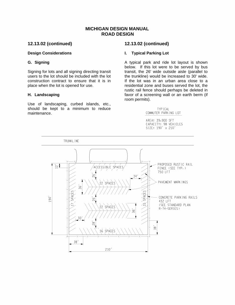
MICHIGAN DESIGN MANUAL
ROAD DESIGN
12.13.02 (continued) Design Considerations G. Signing Signing for lots and all signing directing transit users to the lot should be included with the lot construction contract to ensure that it is in place when the lot is opened for use. H. Landscaping Use of landscaping, curbed islands, etc., should be kept to a minimum to reduce maintenance.
12.13.02 (continued) I. Typical Parking Lot A typical park and ride lot layout is shown below. If this lot were to be served by bus transit, the 26' wide outside aisle (parallel to the trunkline) would be increased to 30' wide. If the lot was in an urban area close to a residential zone and buses served the lot, the rustic rail fence should perhaps be deleted in favor of a screening wall or an earth berm (if room permits).
MICHIGAN DESIGN MANUAL
ROAD DESIGN
12.14 TRUCK TRAPS 12.14.01 Purpose and Description Truck traps, also known as truck escape ramps and arrester beds, are relatively new in Michigan. They are placed on long, steeply descending grades to arrest the progress of a runaway truck that has lost its brakes. The presence of a town, village, or major intersection at the bottom of the grade will usually be a determining factor governing the construction of such a facility. The trap consists of a ramp leading to a bed of "soft" gravel in which the truck will mire down and be stopped. If the ramp and arrester bed can be on an upgrade, so much the better. There is one truck trap in Michigan on M-72 west of Traverse City and west of the M-22 intersection. It was constructed in 1978 at a cost of $66,400.
12.14.02 (revised 12-15-97) Design Details The aggregate in the truck trap should be a rounded, gap-graded natural stone to render the bed both unstable and immune to freezing. Crushed aggregate should definitely not be used. The trap at Traverse City utilizes a bed of peastone 485' long. The bed has 1:2 sloping sides in cut, and the bottom width is 30'. The bottom slopes to one side at 2%. The depth of peastone varies from 1' at the beginning to approximately 3.5' at the end. The ramp leading to the trap is hot mix asphalt, 20' wide, with 5' gravel shoulders.