RnIs y (ensselaer Polytechnic Inst.) i - NASA · 2013-08-31 · RnIs y (ensselaer Polytechnic...
51
LA-B3674 PSER SCANNING LEBO s174168 ND PISD COPRISO ODULATED LPSEN p4. 0 VDGE it I" BRANGE FINDE FOR TERRAIN SENSING ON A RnIs y (ensselaer Polytechnic Inst.) i Troy,20ENwY I *6 S https://ntrs.nasa.gov/search.jsp?R=19740008070 2018-07-28T03:37:14+00:00Z
Transcript of RnIs y (ensselaer Polytechnic Inst.) i - NASA · 2013-08-31 · RnIs y (ensselaer Polytechnic...
LA-B3674 PSER SCANNING LEBO s174168ND PISD COPRISO ODULATED LPSEN p4.
0 VDGE it I"
BRANGE FINDE FOR TERRAIN SENSING ON ARnIs y (ensselaer Polytechnic Inst.) i
Troy,20ENwY
I *6 S
https://ntrs.nasa.gov/search.jsp?R=19740008070 2018-07-28T03:37:14+00:00Z
R.P.I. TECHNICAL REPORT MP-34
LASER SCANNING METHODSAND
A PHASE COMPARISON, MODULATEDLASER RANGE FINDER
FORTERRAIN SENSING ON A MARS
ROVING VEHICLE
by
Glenn T. Herb
National Aeronautics and SpaceAdministration
Grant NGL 33-018-091
A project submitted to the Graduate
Faculty of Rensselaer Polytechnic Jnstitutein partial fulfillment of the
requirements for the degree of
MASTER OF ENGINEERING
School of. EngineeringRensselaer Polytechnic Institute
May, 1973
TABLE OF CONTENTS
LIST OF FIGURES iiiLIST OF TABLES ivACKNOWLEDGMENT vABSTRACT vi
INTRODUCTION 1
PART I Laser Scan Methods 3
I-a Electro-Optics 4I-b Converting Parallel Positions to Angles. 17I-c Scanning Systems 17I-d Incident Spot Distortion 21
Part II Design and Implementation of a Laser RangeFinder Using Phase Comparison Techniques 26
II-a Methods of Laser Rangefinding 26II-b Maximum Modulating Frequency for a Modulated
Laser - Phase Comparison Range Finder 27II-c Improving Resolution with Heterodyning
Techniques 29II-dr The Proposed Range Finder 30II-e Instrumentation of the Rangefinder Electronics 40
CONCLUSIONS 43REFERENCES 44
LIST OF FIGURES
Page1- Deflection in a binary crystal 7
2- Cascading binary deflection units 9
3- Background light vs. modulation voltage deviation 12
4- Angle generation with a simple lens 12
5- Kuriger scanning system 19
6- Proposed scanning system 19
7- Incident spot distortion 22
8- Proposed range finder 31
9- Range finder waveforms 34
10- Range finder output waveform 37
11- Effect of Schmitt trigger on noisey input 42

Iv
LIST OF TABLES
PageTable I- 0/0 in % for several values of d and R 25

V
ACKNOWLEDGMENT
The author wishes to express his gratitude to Prof.
C. N, Shen for his advice, help, and understanding as
faculty advisor during the preparation of this work.
vi
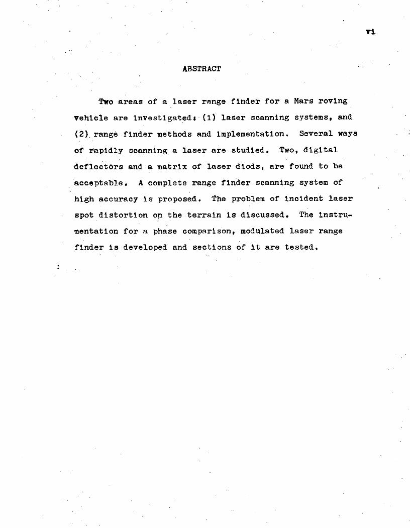
ABSTRACT
Two areas of a laser range finder for a Mars roving
vehicle are investigateds (1) laser scanning systems, and
(2).range finder methods and implementation. Several ways
of rapidly scanning a laser are studied. Two, digital
deflectors and a matrix of laser diods, are found to be
acceptable. A complete range finder scanning system of
high accuracy is proposed. The problem of incident laser
spot distortion on the terrain is discussed. The instru-
mentation for a phase comparison, modulated laser range
finder is developed and sections of it are tested.
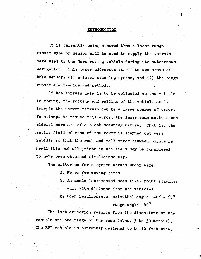
INTRODUCTION
It is currently being assumed that a laser range
finder type of sensor will be used to supply the terrain
data used by the Mars roving vehicle during its autonomous
navigation. This paper addresses itself to two areas of
this sensors (1) a laser scanning system, and (2) the range
finder electronics and methods.
If the terrain data is to be collected as the vehicle
is moving, the rocking and rolling of the vehicle as it
travels the uneven terrain can be a large source of error.
To attempt to reduce this error, the laser scan methods con-
sidered here are of a block scanning nature. That is, the
entire field of view of the rover is scanned out very
rapidly so that the rock and roll error between points is
negligible and all points in the field may be considered
to have been obtained simultaineously.
The criterion for a system worked under were:
1. No or few moving parts
2. An angle incremented scan (i.e. point spacings
vary with distance from the vehicle)
3. Scan requirements- azimuthal angle 400 - 600
range angle 40o
The last criterion results from the dimentions of the
vehicle and the range of the scan (about 3 to 30 meters).
The RPI vehicle is currently designed to be 10 feet wide,
or about 3.1 meters. To cover this width with a scan at 3
meters from the vehicle requires a 600 scan angle (i.e.
-30o from the direction of travel). To cover it at 5
meters requires a 400 scan angle.
Work was also done on instrumentation of the actual
range finder. The method investigated was a phase com-
parison technique using an amplitude modulated laser beam
as the probing element. This method has the advantage that
the range information is contained in the relative phase
of the modulation sinusoid waveform. Thus standard analogue
filter techniques can be used on the detected return wave
to improve its signal to noise ratio.
This paper is divided into two parts. The first part
is a discussion of laser scanning methods. The second part
deals with the range finder instrumentation.
PART I LASER SCAN METHODS
The first method looked at was a system using oscillat-
ing mirrors to do the sweeping. With this system it is very
easy.to synchronize the transmitter and the detector since
both use the same optics. The transmitted pulse is fired,
and the return pulse comes back through the optics 20 to 200
nano-seconds later. The mirrors have essentially not moved
during this time and thus the detector is "looking" at the
same spot at which the pulse was fired.
The problem with this system is that it uses oscillat-
ing mirrors from which the angle data must be taken. At the
scan frequencies of interest (>10 KHz) angle decoders cannot
be used on the oscillating mirrors because of the decoder
disc's non-negligible inertia at those frequencies. Spinning
poly-faced mirrors would solve tho inertia problem, but syn-
chronizing the two spinning mirrors wit' a high degree of ac-
curacy and keeping them synchronized would be an extremely
difficult task. It is therefore felt that this system would
not be satisfactory.
In order to decrease or eliminate this necessity of de-
tecting angle information from a mechanically oscillating
mirror, it seemed that a reasonable approach would be to in-
vestigate electro-optic and other electronic scanners.
I-a Electro-Optics
There are several types of electro-optic devices.
The three considered were acusto-optic beam benders, piezo-
electric deflectors and digital light deflectors.
Acusto-optic beam benders use the property of some crys-
tals which causes their refractive index, n, to have a grad-
ient proportional to a pressure gradient set up in the crys-
tal. Therefore, since light is bent toward an increasing
gradient in the refractive index, by changing the index
gradient of the crystal the deflection of the beam is changed.
In crystals which'possess the acusto-optic property, the
index gradient may be changed simply by changing the pressure
gradient in the material. The major problem with this type
of deflection, however, is that the proportionality constant
between the pressure gradient and the n-gradient is ex-
tremely small [13 . Since the actual scan angle is related
to the index gradiet by the approximations
6e = L (dn/dx) (1)
where 0' = the deflection angle
L = the length of the crystal in the direction of
propagation
dn/dx = the index gradient normal to the direction of
propagation
5
a small proportionality constant between dp/dx (the pressure
gradient) and dn/dx will result in a very small scan angle
for practical values of L. As an example, typical commer-
cial units provide deflection angles on the order of tenths
of degrees. These angles are much too small for our purposes.
.Piezoelectric deflectors use the well known piezoelec-
trio effect of certain crystals which causes them to deform
in certain ways when an electric potential is applied across
them. The most common deformation used are the logitudinal
and the shear deformation. A reflective surface is attached
to one face of the crystal, and it is the motion of this sur-
face as the crystal is deformed which is used to cause the
deflection.
The advantages of this type of deflection is that the
transmitted light pulse and return pulse may use the same
optics. It thus has all the advantages of the vibrating
mirror scan described earlier without the problems assoc-
iated with the mirrors being mec-inically scanned and syn-
chronized. But once again maximum angle is limited. Com-
mercially available units have maximum scans on the order
of 6 [2[2 . Also the angle data must be obtained in-
directly from the analog control voltages.
Digital deflectors are sensitive to the incident light's
direction of polarization. The incident beam will be later-
ally displaced or angularly deflected to one of two possible
positions depending on its direction of polarization.
6
These deflectors consist of a polarization modulator, such
as a Pockel or Kerr cell, which either rotates the direction
of polarization 900 or allows it to pass unrotated, followed
by a binary birefringent discriminator, ie. a crystal with
two indices of refraction depending on the direction of
polarization of the incident light. The number of positions
available at the output of a deflection system can be in-
creased by cascading individual binary units. Properly cas-
cading N of these units results in 2N positions in the final
output. Going from a one dimensional to a two dimensional
scan is easily accomplished by adding an M unit scanner ro-
tated by 900 with respect to the first N units. This results
in an array of 2N by 2M possible deflection positions.
The binary units accomplish a lateral displacement as
shown in figure 1 1[3 . An incident beam of collimated
light will be deflected by an angle 4 if its polarization
direction is in the plane of the crystal's optical axis.
If the direction of polarization is normal to the plane of
the axis, the beam is not deflected at all. When the de-
flected beam hits the edge of the crystal, it is again de-
flected so that it emerges from the unit parallel to the in-
cident beam. Therefore a two dimensional digital scannerN M
will provide a 2 by 2 .matrix of parallel beam positions.
A method of converting these parallel beam scans into ang-
ular scans will be covered later in section I-b.
The angle e' is a function of the crystal material and
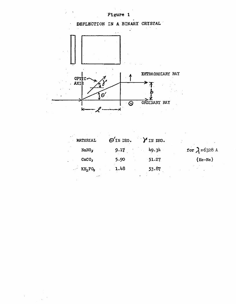
Figure 1
DEFLECTION IN A BINARY CRYSTAL
EXTRAORDIARY RAY
AXI6
'O Ol~ADnlRY RAY
MATERIAL e IN. DEG. IN DEG.
NaNO_ 9.17 49.34 for =6328 A
CaCO3 5.90 51.27 (He-Ne)
KRPO, 1.48 53-87
the angle the optic axis has with respect to the incident
beam. The figure alsogives maximum values of 8' for three
crystal materials and the value of y needed to obtain that
maximum.
Note that in each cell the control voltage is either
present or absent, corresponding to either a rotated polar-
ization in that cell or a non-rotated polarization. There-
fore, each position available at the output can be assoc-
iated with a unique binary code word determined by which cells
are energized and which are not for that point. Thus each
point in the sweep is known exactly by the particular code
word being issued by the control logic at that instant.
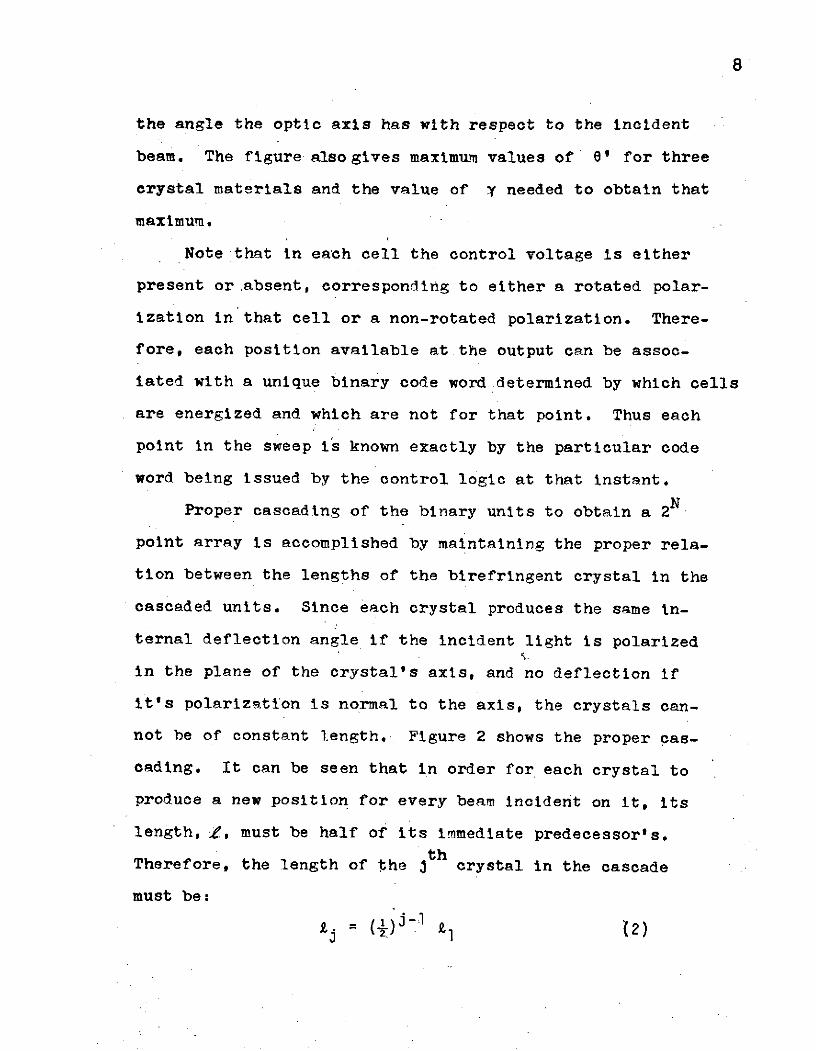
Proper cascading of the binary units to obtain a 2N
point array is accomplished by maintaining the proper rela-
tion between the lengths of the birefringent crystal in the
cascaded units. Since each crystal produces the same in-
ternal deflection angle if the incident light is polarized
in the plane of the crystal's axis, and no deflection if
it's polarization is normal to the axis, the crystals can-
not be of constant length. Figure 2 shows the proper cas-
cading. It can be seen that in order for each crystal to
produce a new position for every beam incident on it, its
length, 1, must be half of its immediate predecessor's.
Therefore, the length of the jth crystal in the cascade
must be:
j T ) -2)
9
Figure 2
CASCADING BINARY DEFLECTION UNITS
X1 i2 X3
-4 -- - - 7 :- 0- - - - - - --- - 0 0- "- 0 0 1
-,- -- - . ....-- 0 1 1--- 0010
S--- 1 1 1--- 11
-- - -- 1 0 1
'S ------ 1 0 00 1
x2 x3
X=i Polarization Rotated
X=0 No Rotation
Note position lables form a 'cyclic' binary code
10
There are several problems with these binary units,
however. To rotate the polarization of light by 900 in a
Pockles cell, the half wave voltage must be applied to the
cell in such a way as to set up an electric field in the
cell parallel to the direction of light propagation. To
accomplish this, electrodes must be placed in the optical
path. This then creates the problem of finding the optimum
compromize between the two competing requirements of low
resistance electrodessand maximum transmittance of light
by th electrodes. Kulcke found highly acceptable results
could be obtained using a variety of electrode - adhesive
combinations [3]. It was also found that the modulator
electrode transmittance was the limiting factor and hence
the total system transmittance could be approximated as
St2nT s y s t (3)
where t is the transmittance of an electrode - adhesive
combination, and n is the number of cells in the system (2n
appears because there are two electrodes per modulator).
Another problem of discriminator cells is background
light, that is light appearing at a point or points other
than the one called for. The major cause of-this is devia-
tion of. the modulator's control voltage from the required
half wave voltage. As the control voltage becomes greater
than or less than the half wave voltage, the polarization
of the light is rotated more or less than 900. It will then
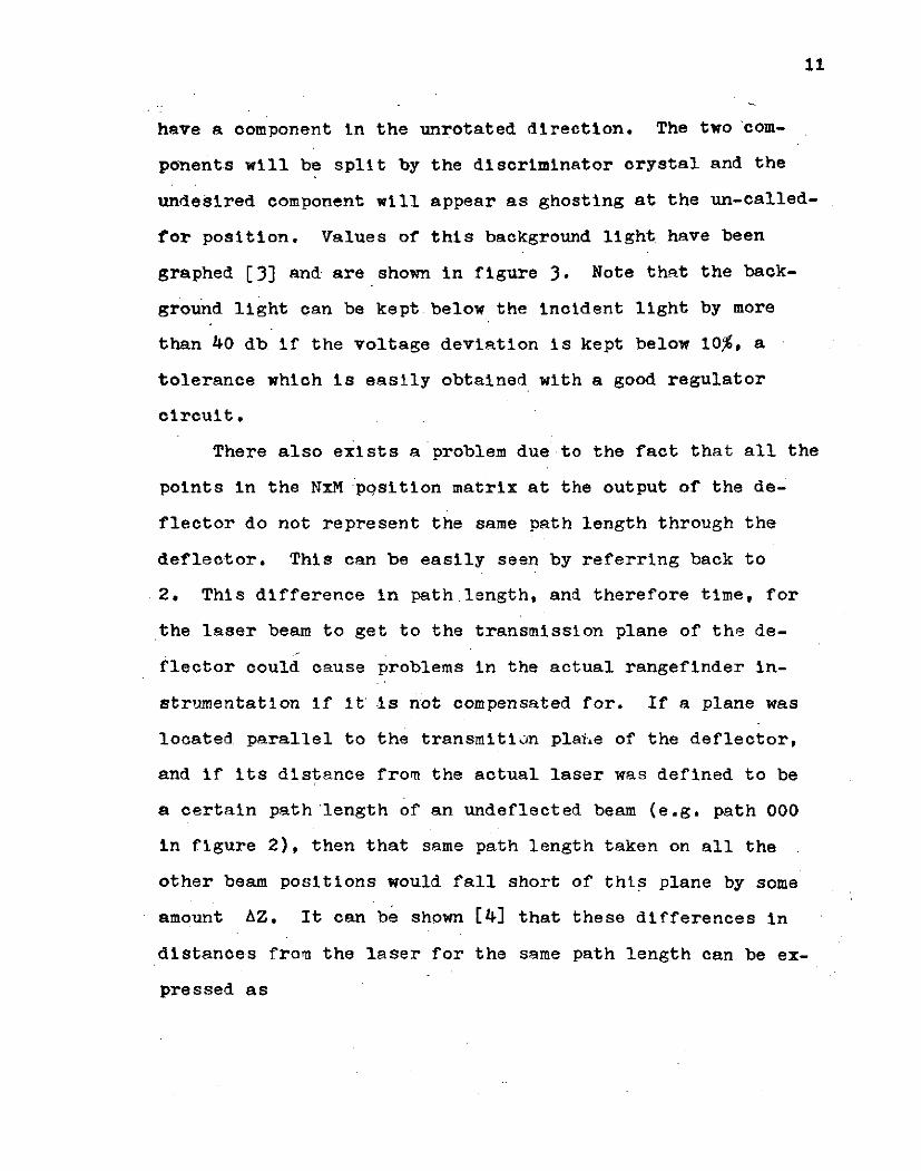
have a component in the unrotated direction. The two com-
ponents will be split by the discriminator crystal and the
undesired component will appear as ghosting at the un-called-
for position. Values of this background light have been
graphed [3] and are shown in figure 3. Note that the back-
ground light can be kept below the incident light by more
than 40 db if the voltage deviation is kept below 10%, a
tolerance which is easily obtained with a good regulator
circuit.
There also exists a problem due to the fact that all the
points in the NxM pqsition matrix at the output of the de-
flector do not represent the same path length through the
deflector. This can be easily seen by referring back to
2. This difference in path.length, and therefore time, for
the laser beam to get to the transmission plane of the de-
flector could cause problems in the actual rangefinder in-
strumentation if it' is not compensated for. If a plane was
located parallel to the transmition plaie of the deflector,
and if its distance from the actual laser was defined to be
a certain path 'length of an undeflected beam (e.g. path 000
in figure 2), then that same path length taken on all the
other beam positions would fall short of this plane by some
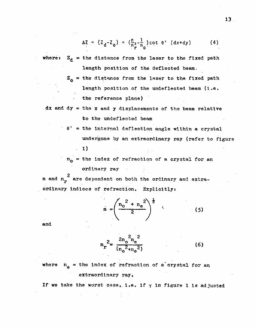
amount AZ. It can be shown [4] that these differences in
distances from the laser for the same path length can be ex-
pressed as
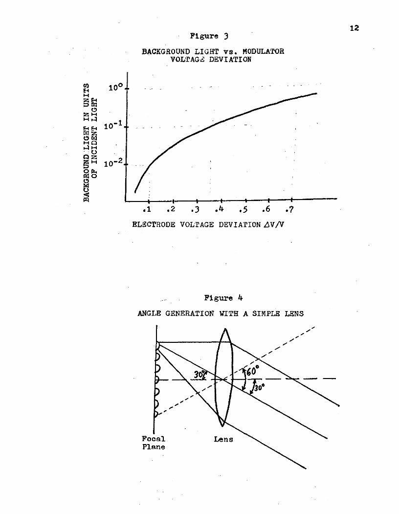
12Figure 3
BACKGROUND LIGHT vs. MODULATORVOLTAGE DEVIATION
ca 100
S 1 0 - 1
H 1 0 - 2
.1 .2 .3 .4 .5 .6 .7
ELECTRODE VOLTAGE DEVIATION AV/V
Figure 4
ANGLE GENERATION WITH A SIMPLE LENS
Focal LensPlane
13
Z=Zd ) = (2 )Ct 0' (dx+dy) (4)r 0o
wheres Zd = the distance from the laser to the fixed path
length position of the deflected beam.
Zo = the distance from the laser to the fixed path
length position of the undeflected beam (i.e.
the reference plane)
dx and dy = the x and y displacements of the beam relative
to the undeflected beam
0' = the internal deflection angle within a crystal
undergone by an extraordinary ray (refer to figure
1)
no = the index of refraction of a crystal for an
ordinary ray2
n and nr are dependent on both the ordinary and extra-
ordinary indices of refraction. Explicitlys
no + nen = 2 (5)
and
2 2 n 2
n 2n (6)r (no 2 +ne2)
where ne = the index of refraction of a crystal for an
extraordinary ray.
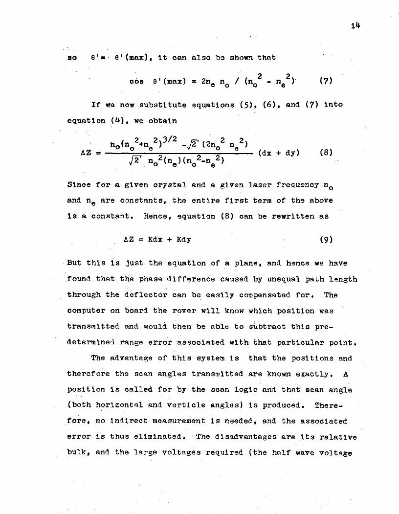
If we take the worst case, i.e. if y in figure 1 is adjusted
14
so e'=. 6'(max), it can also be shown that
2 2cos 8'(max) = 2ne no / (no - ne (7)
If we now substitute equations (5), (6), and (7) into
equation (4), we obtain
no(n 2+ne2)3/2 -2(2n 2 n)AZ = (dx + dy) (8)
2 no2(ne)(no2-ne2)
Since for a given crystal and a given laser frequency no
and ne are constants, the entire first term of the above
is a constant. Hence, equation (8) can be rewritten as
AZ = Kdx + Kdy (9)
But this is just the equation of a plane, and hence we have
found that the phase difference caused by unequal path length
through the deflector can be easily compensated for. The
computer on board the rover will know which position was
transmitted and would then be able to subtract this pre-
determined range error associated with that particular point.
The advantage of this system is that the positions and
therefore the scan angles transmitted are known exactly. A
position is called for by the scan logic and.that scan angle
(both horizontal and vertiole angles) is produced. There-
fore, no indirect measurement is needed, and the associated
error is thus eliminated. The disadvantages are its relative
bulk, and the large voltages required (the half wave voltage
15
of a Pockels cell is on the order of a kilovolt). Also the
return beam cannot use the same optics.
Power dissipation for this type of deflector can be
estimated by investigating the polarization modulators used.
If we consider using a Pockels cell of KH 2 PO as our modu-
lator, we can use the known [4] approximate dissipation
equation
W s (0.938+1.94x10o-3T) x 10-6 ab joules (10)dis cell/cycle
where, Wdis = the dissipated energy per cell per cycle
T = the temperature above the cell's Curie
temperature
a, b, and c = the dimensions of the cell in the horizontal,
vertical, and direction of light propagation,
respectively
For an NIM matrix of positions, we will have NxM Pockels
cells. But since the positions are called for in a Gray
code order (recall figure 2), onl: one Lell is switched at
any time, and the switching frequency of the cells goes
down as their "significance" in the Gray code word goes up.
Hence total power dissipation will be
n-2 n-1P Wdis ifs + W f + + +W () f + W 2(j) f sdsdis dis s dis
Wdis( + + + ()n-2 + 2( ) ) f (11)
where fs = the position switching frequency, and n = N+M.
16
But the series in brackets in equation (11) is always equal
to unity. Hence
P dis Wdis f watts (12)
An alternative to the digital deflector optics is a
matrix of N by M individual laser diodes. This has all the
advantages of the binary deflectors, but lacks the problem
of high voltages and is somewhat less bulky. In addition,
this type of system offers the option of predistorting the
matrix. That is, if a non-uniform matrix of scan locations
on the terrain is desired, or if a data point layout other
than the equal angle incremented scan is wished to be sim-
ulated, the individual diodes can be shifted around on the
transmission plane of the scanner. This pre-distorted ma-
trix when passed through the angle generating optics describ-
ed in the next section, will result in the desired non uniform
scan.
A very important advantage of this system is that the
laser duty cycle of the entire system can be quite high
while keeping the duty cycle of the individual laser diodes
quite low. For example, if it takes one millisecond to
interrogate a data point and if a grid of 500 data points is
interrogated once every 5 seconds, the system laser duty
cycle will be 10%, while the individual diodes' duty cycles
will be a much more realistic .02%.
The disadvantage of this type of system is that it
17
requires N times M diodes whose alignment is critical. In
addition, only semiconductor lasers can be practically used.
I-b Converting Parallel Positions to Angles
The last two methods both provide parallel light out-
puts. This must be converted to scan angles if the method
is to be useful in a scanning system.
This can be accomplished by placing the origin of the
parallel positions on the focal plane of a small apature
lens. This is shown in figure 4 for the case of a matrix
of laser diodes, i.e. uncollimated light. The case of
binary deflection optics with collimated light is similar
except that instead of collimating, the lens simply deflects
the beam almost as if it were an ideal nray".
I-c Scanning Systems
One possible system, the dual vibrating mirror scan,
was mentiuned earlier in this paper. Here, two more systems
will be introduced which attempt to alleviate the problems of
the dual mirror approach.
Kuriger [5] has worked on and proposed a hybrid scan
system using a vibrating mirror for a verticle scan and
a line of laser diodes to accomplish the horizontal scan.
His range finder system is not capable of producting the
necessary accuracy, but his scanning system does have some
advantages. Kuriger's system is presented with some minor

18
modifications in figure 5. The "pulse transmitted detector"
has been added to conform with the information needed in one
of the range finding schemes currently under study. In
this system both the transmitter and the detector use the
.same verticle scan mirror. The diodes provide the hori-
zontal scan, while the receiver looks at the entire hori-
zontal scan area via the cylindrical lens. The use of the
same scan mirror assures synchronization between transmitter
and reciever, and the narrowing of the detector's field of
view to only one horizontal row at a time increases the
signal to noise ratio. Further advantages of this system
are its compactness and small number of components. But
although the horizontal transmitted angle is known exactly,
the verticle angle determination relies on the same type
of mirror position detection as does the dual mirror system
and suffers the same problems,
An alternative system which seems to avoid all the
major scan problems is now presented. Figure 6 shows the
proposed system using digital deflection optics, but a
matrix of laser diodes could be substituted just as well.
The detection system used is similar to Kuriger's
except the detector section is mechanically a separate
entity from the transmitter. When the mirror drive starts
its verticle sweep, the synch (start) circuit detects this
and initiates the transmitter's scan. The transmitter's
verticle scan is approximately synchronized to the mirror,
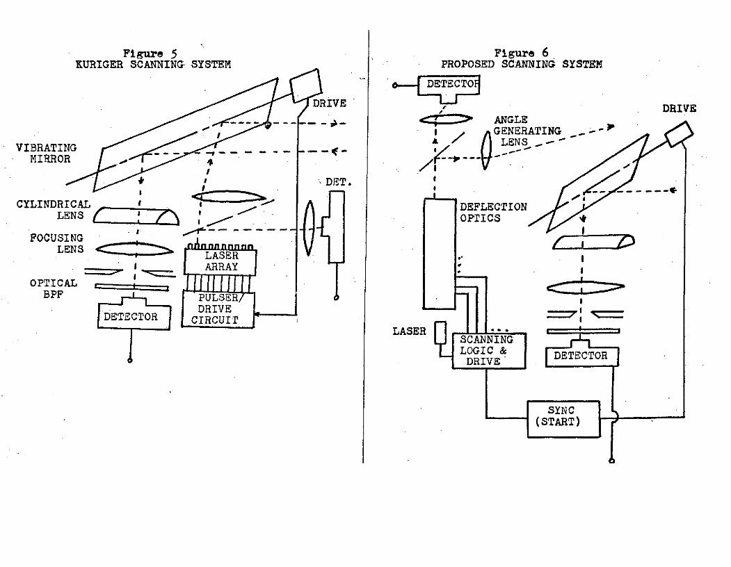
Figure 5 Figure 6KURIGER SCANNING SYSTEM PROPOSED SCANNING SYSTEM
DRIVE DRIVEDRIVES... ... ANGLE
GENERATING
VIBRATING A
MIRROR 4 1
' ? I DET.
CYLINDRICAL DEFLECTIONLENS OPTICS
S-- - -- I~2FOCUSING - --
LENS LASER
I ARRAY
OPTICALBPF PULSER
SCANNING
DRVERIVE
SYNC(START)
20
but the detector is given a wide enough field of view to
compensate for a slight mis-match. Any mis-match which does
occur does not continue to accumulate since the transmitter
and detector are re-synchronized at the beginning of each
vertical scan.
,The advantages of this system are many-fold. First, the
actual laser scanning is completely solid state. Also the
transmitted angles are known exactly, with each pair of
horizontal and verticle having its own binary code lable.
Finally, although a hybrid detector scheme is used, data
point accuracy is extremely improved because we are not
relying on the mirror position to give point location, only
to narrow the detector's field of view to the approximate
azimuthal scan line of the transmitter. This system then
seems to have the potential for extremely accurate trans-
mitted angle information while maintaining a reasonable
signal to noise ratio at the detector by narrowing its
field of view,
The maximum scan angle obtainable with this system is
determined by the angle generating lens system used. For
the single lens set up shown in figure 3, maximum scans of
550 can be obtained with a good lens. If a multiple lens
system is used, this "viewing angle" can be greatly extended
from this maximum. For example, using standard photograph-
to lenses as a guide, a 28 mm focal length lens (6 elements)
has a viewing angle of 74 , a 20 mm lens (11 elements) has a
21
viewing angle of 940. If distortion of field is allowed
(an effect which can be compensated for by appropriate
placement of beam sources on the matrix plane) fisheye
lenses can also be used. Fisheye lenses have viewing angles
from 1800 (10 mm focal length) to 2200 (6 mm focal length).[6]
Since all lenses are circular, the angle maximum is
completely symetric with respect to the optic axis and
therefore holds for both azimuthal and range angles.
Scan rate is limited only by position switching time.
For the case of a mqtrix of laser diodes, minimum switching
time is caused by the diodes' minimum pulse width and the
maximum usable frequency of the driver circuits. This is on
the order of magnitude of 100 KHz or 10 microseconds per
position. Thus the limiting factor for sweep rate will not
be the scan unit, but rather the minimum on-time of the laser
needed by the range finder system, This will be much larger
than 10 micro seconds.
For a matrix of diodes systen the aight of this scan
mechanism will most likely be under 10 pounds.
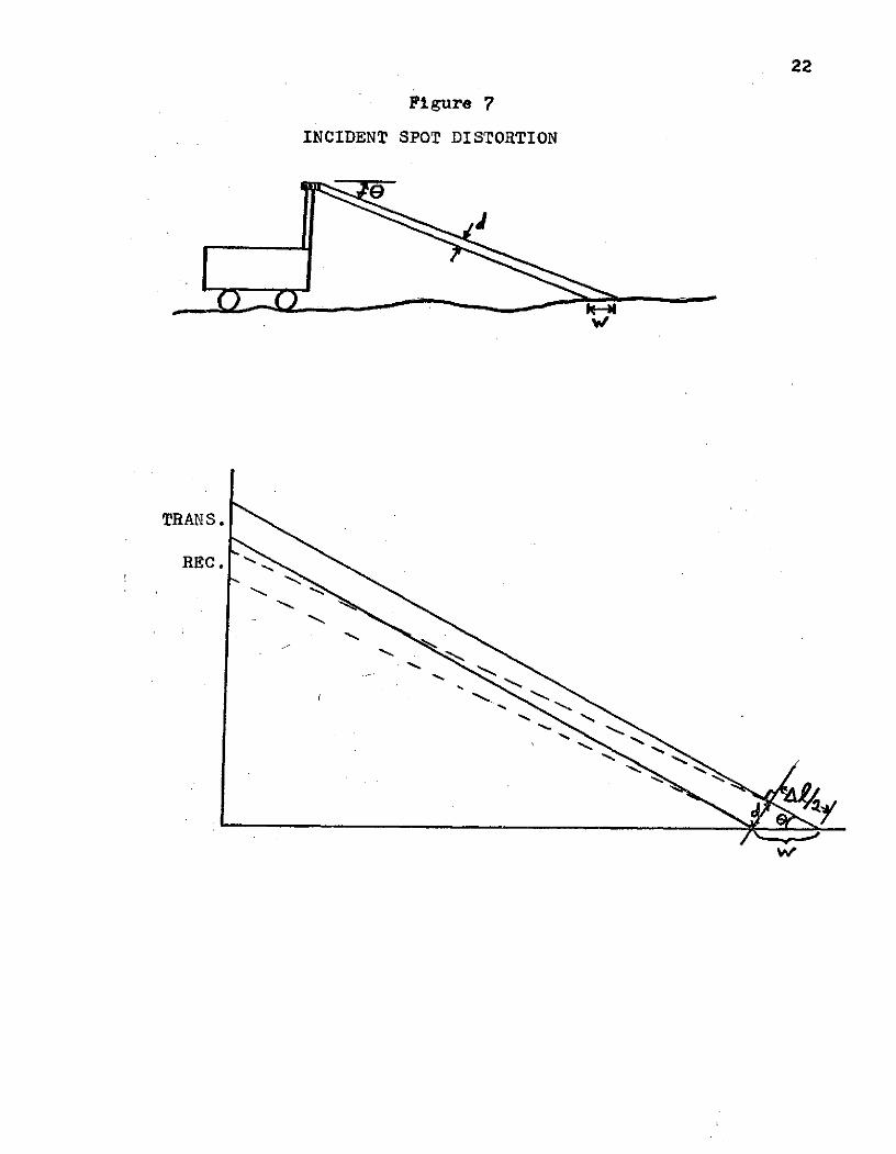
I-d Incident Spot Distortion
One problem with all the angular scan methods is the
incident spot distortion At the terrain. Since a collimated
beam is transmitted at an angle, the actual shape and size
of the spot will be distorted when it strikes all surfaces
other than those to which it is normal (see figure 7). This
22
Figure 7
INCIDENT SPOT DISTORTION
TRANS.
REC.
23
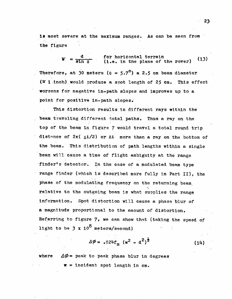
is most severe at the maximum ranges. As can be seen from
the figure
d, for horizontal terrainsin e (i.e. in the plane of the rover)
Therefore, at 30 meters (e = 5.70) a 2.5 cm beam diameter
(Y 1 inch).would produce a spot length of 25 cm. This effect
worsens for negative in-path slopes and improves up to a
point for positive in-path slopes.
This distortion results in different rays within the
beam traveling different total paths. Thus a ray on the
top of the beam in figure 7 would travel a total round trip
distance of 2x( At/2) or At more than a ray on the bottom of
the beam. This distribution of path lengths within a single
beam will cause a time of flight ambiguity at the range
finder's detector. In the case of a modulated beam type
range finder (which is described more fully in Part II), the
phase of the modulating frequency on the returning beam
relative to the outgoing beam is what supplies the range
information. Spot distortion will cause a phase blur of
a magnitude proportional to the amount of distortion.
Referring to figure 7, we can show that (taking the speed of
light to be 3 x 10⁸ meters/second)
95= .024fm (W2 - d2 (14)
where AO= peak to peak phase blur in degrees
w = incident spot length in cm.

24
d = beam diameter in cm.
f = modulating frequency in MHz
But since
5= ( At)rf360 (15)
where Z = relative receiver to transmitter phase of mod-
ulating frequency
At = beam ideal round trip transit time in microseconds
we see that the error introduced by the phase blur is
0 .024 (w2 - d2)1 (16)S360 At
Note that equation (16) is independent of fm. Therefore,
the phase blur error is independent of the beam's mod-
ulating frequency. It is therefore free to be chosen by
other constraints.
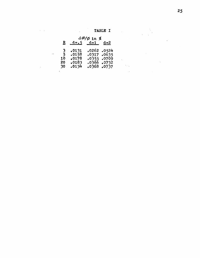
Table I shows values of AO/V5 as a function of
range in front of the vehicle, R, and beam diameter, d.
This can be done since R is a function of e and w is a
function of d and e (recall equation 13). Note that the
errors introduced by spot distortion on a flat terrain.
are negligably small over a large range of d (the accuracies
desired are in the range of .1% to 1% - see section II-c).
25
TABLE I
S/A in %R d =. d=1 d=2
3 .0131 .0262 .05245 .0158 .0317 .0635
10 .0178 .0355 .070920 .0183 .0366 .073230 .0134 .0368 .0737
26
PART II DESIGN AND IMPLEMENTATION OF A LASER RANGEFINDER
USING PHASE COMPARISON TECHNIQUES
II-a Methods of Laser Rangefinding
The simplest type of laser rangefinding is the timed
pulse method. The laser is simply pulsed for a very short
time and the detector watches for the reflected return
pulse. The time between the pulse's transmission and its
detection is then timed and this time of flight information
is converted to range data.
An alternate method is the modulated laser beam-phase
comparison method. In this scheme the laser is amplitude
modulated with a high frequency. This necessitates a much
longer laser pulse than the previous method since the lasert s
unmodulated component of power output must reach a steady
state value and stay there long enough for good data to be
obtained.
The detector receives the reflected lasers output. The
radio frequency modulating signal is then removed from the
detected signal and put through a very narrow band (high Q)
band pass filter. This very high Q filter tends to block
the large amount of noise that will be imposed on the laser
signal in the process of its bouncing off the terrain.
The processed RF signal is now phase compared with the
source which is providing the modulating frequency. Since the
return signal has gone through a longer path then the source.
27
signal in getting to the phase comparitor, it will be de-
layed in phase by an amount proportional to that increased
path length. Hence, the detected phase difference is pro-
portional to the range as seen by the laser.
The ability to use common and relatively simple analog
filters to, obtain a great increase in signal to noise is
one of the major reasons that this method seems so promis-
ing. In the timed pulse method, on the other hand, a
noisy returned pulse will cause a large problem in decid-
ing when to stop the time of flight counter. But since the
noise also severely distorts the pulse's shape, there is no
easy filtering scheme that can be employed to improve the
signal to noise ratio. The modulation scheme does, however,
require a longer laser pulse width than the timed pulse
method. Therefore, it will require more power, but in re-
turn one obtains the signal to noise ratio improvement
desired with more ease. The rest of this paper deals
solely with the modulation method of range finding.
II-b Maximum Modulating Frequency for a Modulated Laser -
Phase Comparison Rangefinder
The modulation frequency of the laser is determined
by the ranges of interest (recall it was shown in section
I-d that our choice of frequency is not constrained by
spot distortion/ phase blur requirements). The phase
delay introduced into the modulating frequency due to the
28
path length of the laser must not be allowed to become
greater than or oqual to 3600 since, for example, 3700 is
ambiguous with 100, etc. This requirement implies that our
maximum frequency will be set by the maximum range. Re-
calling equation (15) and solving it for fm' we have
f(17)S = ( At)3600 (17)
To find the upper limit on fm we set 0 = 3600. Therefores
fm(max)< 1 (18)Atm
where Atm = the maximum round trip transit time of the laser
beam.
Since At = 2R'/c (19)
where R' = the actual one way path length of the laser beam
o = the speed of light,
we can estimate a maximum frequency by noting that at large
ranges in front of the vehicle,the horizontal range from the
vehicle, R, is approximately equal to R'. At R = 30 meters
this is a good approximation (for a mqst height of 3 meters).
Therefore, our maximum frequency is
f (max) 0)/35 MHz. (20)
29
II-c Improving Resolution with Heterodyning Techniques
The accuracy we are looking for is on the order of +1 cm
in the mid range of the scanning field (3 to 30 meters).
This scanning field corresponds to round trip times of
approximately 20 to 200 nanoseconds and the accuracy re-
quirement calls for a resolution on the order of .1 nano-
seconds. This resolution is extremely difficult if not
impossible to attain using current technology and consider-
ing the device's working environment. But remember these
times are represented by phase differences between the re-
turn signal and the "in house" or modulating signal. These
phase differences range from 0 to 360 degrees. From ele-
mentary modulation theory, it is known that if two sinu-
soids of different frequencies are multiplied together,
one of the components of the resultant output is a sinu-
soid whose frequency is the difference of the two original
inputs. Also, if one of the two original inputs has a
constant phase term, this term will be'maintained and the
lowest frequency component of the output will be the
difference frequency with a constant phase angle equal to
the input angle, i.e. sin [(wl-m 2 )t + 11'
This effect proves very useful in expanding the time
base of the information carrying phase angle of the return
signal of the laser. For example, one way of comparing
phase is to check corresponding zero crossings of two signals
and see how far behind one lags the other. For a 1 MHz
30
modulation frequency say the return beam has experienced a
450 phase delay with respect to the "in house" reference
signal. Using the zero crossing method, a 450 delay at
1 MHz means that the return signal will lag by 125 nano-
seconds. If before the phase comparison is done, however,
both the returned signal and the in house reference signal
are heterodyned to some lower frequency, the phase difference
between them will be preserved,but the time between res-
pective zero crossings will have been expanded. In the
example cited above, if the 1 MHz signals are heterodyned
down to 10 KHz, the 450 phase difference will be maintained,
but 450 at 10 KHz using the zero crossing method means that
the return signal will lag by 12.5 microseconds. Therefore,
heterodyning the signal down by a factor of 100, results in
expanding the phase difference in time by a factor of 100.
For a given system clock frequency, we have, therefore,
increased our resolution by 100 times.
This heterodyning scheme is used in the proposed range
finder design which is described in the next section.
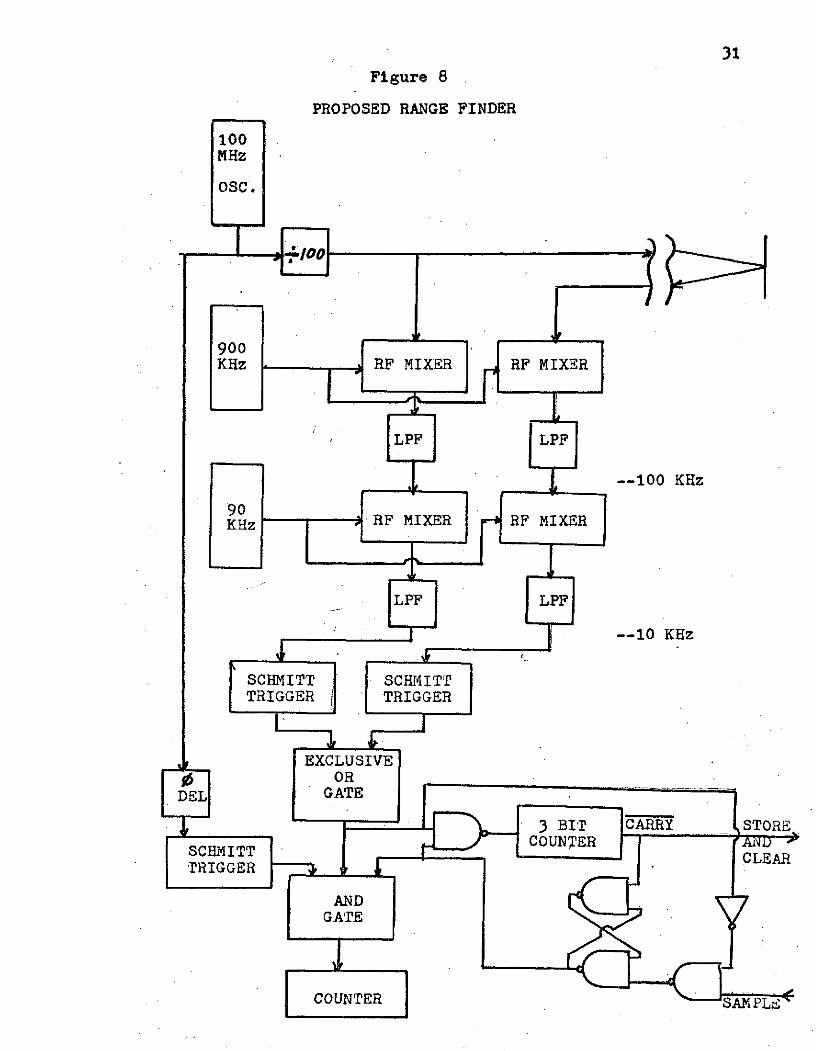
II-d The Proposed Range Finder
A block diagram of the proposed range finder elec-
tronics is shown in figure 8. A 1 MHz main oscillator has
been illustrated,but recall from section II-b that we may
theoretically use up to a 5 MHz oscillator. The actual
laser modulator and detection circuits are indicated by the
31
Figure 8
PROPOSED RANGE FINDER
100MHz
OSC.
900KHz -RF MIXER RF MIXER
LPF LPF
--100 KHz
90K~z )RF MIXER I RF MIXER
LPF ILPF
--10 KHz
SCHMITT SCHMITTTRIGGER TRIGGER
EXCLUSIVE, ORDEL GATE
G3 BIT CARRY STORE
CHMITT COUNTER ACLEARIRIGGER
ANDGATE
COUNTER Zip
32
broken line at the top of the page. It is also assumed
that the signal enhancing and filtering described in section
II-a has been incorporated in the detection circuits, and
the returned signal input to the shown system is this
preprocessed signal.
The heterodyning method of resolution expansion de-
scribed in the previous section is incorporated here and
is shown as a two step downward frequency translation by a
factor of 100. The two steps are used to provide more
stability. Since the down converting is a subtraction
process,and subtraction of two large numbers which are close
in magnitude tends to be a major error source, multiple
stage down converting helps to provide greater stability
in the final output frequency.
Note that both the returned signal and the in house
reference signal go through the same processing. This is
done to ensure that the phase difference that exist before
the heterodyning is the same phase difference that exists
after the down converting. By heterodyning both signals
simultaneously, any phase error which is introduced by any
of the local oscillators (the 900 KHz and 90 KHz sources in
the figure) is added to both the returned and reference sign-
als. Therefore, the phase difference between them remains
the same. The low pass filter (LPF) following each mixer
passes only the lowest frequency component of the mixer
output which is the desired difference frequency.
33
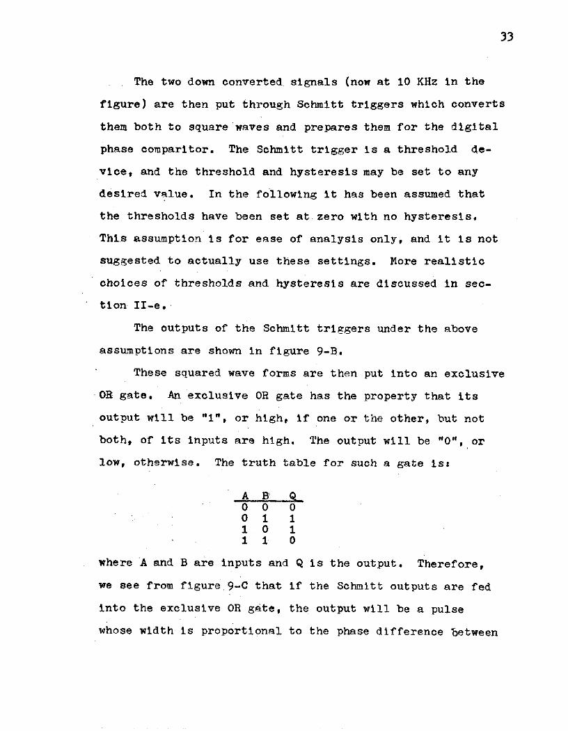
The two down converted signals (now at 10 KHz in the
figure) are then put through Schmitt triggers which converts
them both to square waves and prepares them for the digital
phase comparitor. The Schmitt trigger is a threshold de-
vice, and the threshold and hysteresis may be set to any
desired value. In the following it has been assumed that
the thresholds have been set at zero with no hysteresis.
This assumption is for ease of analysis only, and it is not
suggested to actually use these settings. More realistic
choices of thresholds and hysteresis are discussed in sec-
tion II-e.
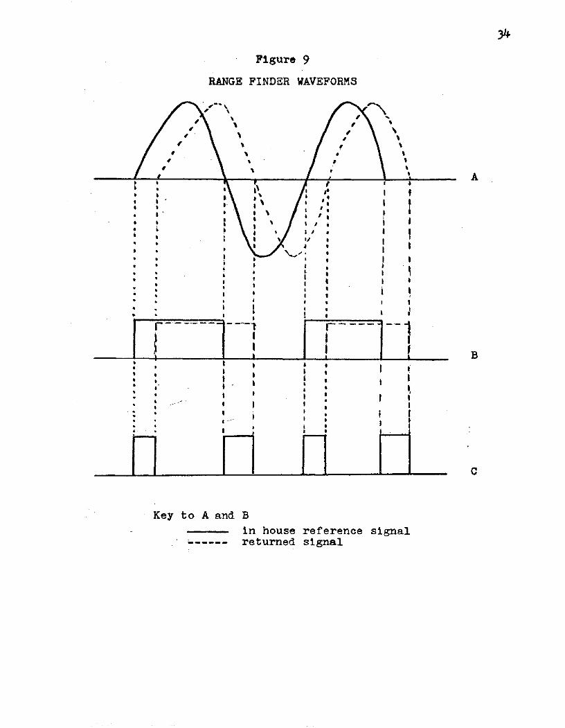
The outputs of the Schmitt triggers under the above
assumptions are shown in figure 9-B.
These squared wave forms are then put into an exclusive
OR gate. An exclusive OR gate has the property that its
output will be "1", or high, if one or the other, but not
both, of its inputs are high. The output will be "0", or
low, otherwise. The truth table for such a gate is:
A B. Q00 00 1 11 0 11 1 0
where A and B are inputs and Q is the output. Therefore,
we see from figure 9-C that if the Schmitt outputs are fed
into the exclusive OR gate, the output will be a pulse
whose width is proportional to the phase difference between
34
Figure 9
RANGE FINDER WAVEFORMS
I •\, ' 'N ,.
1 1
r~ r eI a ,
• " . * 's I
I I a? A
ii a I I
• 1
* * ! , o
a * * 7
* s *
I I , I
, I I
• ' I I
I I I
i .... I II 1
a I -
:* " a I-
. a. I I L I
Key to A and B
,, in house reference signalreturned signal
II iI I _ _
I a a
- Ia I a I
Key to A and B
in house reference signal----- returned signal

35
the squared in house reference signal and the squared return
signal. This pulse contains the desired phase (and therefore
range) -information that is being sought.
To extract the phase information from this pulse,
its length must be determined. To do this digitally,the
pulse must be timed by a system clock. Recalling figure 8,
we note that the 1 MHz modulating frequency was obtained by
counting down by 100 from a 100 MHz master oscillator. This
100 MHz source frequency (which will be in phase with the
1 MHz modulation frequency) can then be used as a system
clock. The frequency is then put through a sine to square
wave converter or a Schmitt trigger and the resulting square
waves are used to time the exclusive OR output pulse.
One section neglected in the above paragraph is the
phase delay (0 DEL) block shown in the master clock's path
in figure 8. This is added to take advantage of the fact
that the clock frequency and the modulating frequency are
initially in phase. Since the modulating frequency has gone
through the heterodyning equipment, it has experienced a
phase delay with respect to the master oscillator at the
point where it enters the Schmitt trigger. To compensate
for this delay and bring the two frequencies back in phase
again, the phase delay block is added in the master clock's
path. This delay is adjusted so that it equals the delay
introduced by the heterodyning path.
The advantage that is obtained by having the system clock
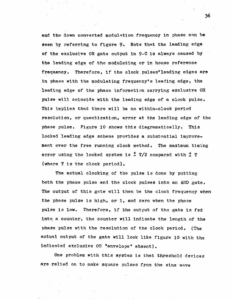
36
and the down converted modulation frequency in phase can be
seen by referring to figure 9. Note that the leading edge
of the exclusive OR gate output in 9-C is always caused by
the leading edge of the modulating or in house reference
frequency. Therefore, if the clock pulses'leading edges are
in phase with the modulating frequency's leading edge, the
leading edge of the phase information carrying exclusive OR
pulse will coincide with the leading edge of a clock pulse.
This implies that there will be no within-clock period
resolution, or quantization, error at the leading edge of the
phase pulse. Figure 10 shows this diagramatically. This
locked leading edge scheme provides a substantial improve-
ment over the free running clock method. The maximum timing
error using the locked system is t T/2 compared with ± T
(where T is the clock period).
The actual clocking of the pulse is done by putting
both the phase pulse and the clock pulses into an AND gate.
The output of this gate will then be the clock frequency when
the phase pulse is high, or 1, and zero when the phase
pulse is low. Therefore, if the output of the gate is fed
into a counter, the counter will indicate the length of the
phase pulse with the resolution of the clock period. (The
actual output of the gate will look like figure 10 with the
indicated exclusive OR "envelope" absent).
One problem with this system is that threshold devices
are relied on to make square pulses from the sine wave
37
Figure 10
RANGE FINDER OUTPUT WAVEFORM
Exclusive ORL Output
'Clock' Pulses
Can -Turn OffControl 10 Error
Clock Phase So'No' Tu n On
Error _"
38
inputs. Thus any noise which still exists on the returned
signal at this point is very likely to cause either pre-
mature or late firing of the Schmitt trigger. This will
cause a corresponding phase error in that cycle of the re-
turned signal. However, since the noise, and hence its
resulting.phase error, are random, the error of the final
phase (i.e. range) measurement can be significantly reduced
by averaging several phase differences and considering this
average to be the range data for that point. This averaging
is accomplished by the circuit in the lower right corner of
figure 8. One output of this circuit is the third input
to the phase clocking (master) AND gate. This input has
the function of enabling the gate for a specified number
of phase pulses and then disabling the gate until another
SAMPLE command has been given.
The simplified operation of this averaging circuit is
as follows. The system timer generates a SAMPLE command.
To insure that the main AND gate is not enabled during the
middle of a phase pulse (which would cause the first sample
to be a short count), the SAMPLE command is momentarily
disabled if a phase pulse is present at the AND gate input.
There is therefore a minimum pulse width for the sample
command, but this is not a problem. Once the existing
phase pulse (if any) ends, the SAMPLE command is allowed
through and it sets the RS flip-flop (the two cross coupled
39
NAND gates). Setting this flip-flop causes the phase
clocking AND gate and the sample counter (the 3 bit counter)
to be enabled. The phase pulses are now clocked and their
lengths stored in the counter as described above, but now
several phase pulse widths are added up in the counter.
The 3 bit counter counts the number of phase pulses that
are added in the main counter. Since this monitoring counter
is a 3 bit counter,Ait will generate a carry pulse on the
eighth phase pulse. This carry pulse is used to reset the
RS flip-flop, thus disabling the AND gate after 8 phase
lengths have been added in the main counter. Note that
since a power of 2 number of samples has been added, the
division required to obtain the true average pulse width
(if that is what is desired), is done trivially by simply
shifting the counter's binary outputs 3 bits,-i.e., by
moving the binary point 3 bits to the left. The carry
pulse also acts as a store and clear initiating signal which
tells the computer that range data is available and should
be stored after which the counter should be cleared.
The eight samples that are needed can be obtained
from one laser pulse, since one modulated pulse contains
many cycles of the modulating waveform. The number of
samples used in the averaging will, however determine the
minimum width of the laser pulse. To find this minimun
width briefly recall figure 9. Note that there are two
40
phase pulses generated for every cycle of the time expanded
of down translated modulating frequency. Therefore to
measure eight phase pulses, we must wait for four cycles at
the lower frequency. In the system under consideration,
this lower frequency is 10 KHz. Hence eight samples will
take .4 milliseconds. Allowing for the laser's rise time
and heterodyning stabilizing time, this indicates the laser
pulse must be on the order of a millisecond.
II-e Instrumentation of the Rangefinder Electronics
The phase detection section of the rangefinder was
bread-boarded in the laboratory to check its operation.
Due to equipment problems the heterodyning section could
not be simulated, but this will hopefully be done in the
coming months by a new member of the project team (interest-
ed readers should consult next year's reports for possible
results). Without the frequency translating section, the
phase conparitor had to be checked with a lower frequency.
The time expansion feature was also lost. Phase delays of
sufficient magnitudes for the comparitor to resolve thus
had to be artificially produced. These phase differences
therefore represented no actual range measurements, but
were for test purposes only.
Since this self contained system had no significant
noise, the Schmitt triggers were set at the more easily im-
plemented threshold- of zero with .zero hysteresis (in
actuallity simple comparitors were used). In the actual
system, more realistic values of the thresholds of say
+Vtand -Vt should be chosen. The choice of Vt is not im-
mediately obvious. The most logical place to locate this
threshold voltage at first glance, is at the point of max-
imum slope of the signal, since this would reduce the sensi-
tivity of the trigger to premature or late switching due to
noise spikes close to the theshold. However for sinusoids
this point is at zero voltage, which eliminates the hyster-
esis region and it is the hysteresis that reduces the sensi-
tivity to premature OFF switching of the trigger after it
has just crossed the ON threshold and vice versa (see
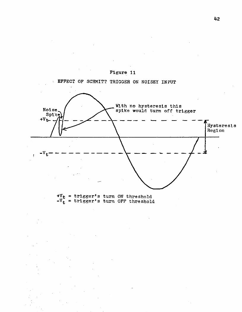
figure 11). Thus the actual hysteresis, and therefore
thresholds, should be set as a function of the most probable
noise amplitude of the processed signal,
As for the system under test, all sections worked
as expected. The output wave closely resembled figure 10
(with the exclusive OR envelope missing of course). Since
NAND logic was used; however, the wave forms were inverted.
With the SAMPLE command held high, the clocked phase
pulses were grouped into the appropriate number of samples
for averaging. Varying the phase angle of the input signals
varied the phase pulse width,and therefore the number of
pulses in the output count, by a proportional amount.
42
Figure 11
EFFECT OF SCHMITT TRIGGER ON NOISEY INPUT
With no hysteresis thisNoise spike would turn off trigger
Spike
HysteresisRegion
-Vt-
+Vt = trigger's turn ON threshold-V t = trigger's turn OFF threshold
43
CONCLUSION
A rapid scanning laser range finder was shown to be
a feasable system. A non-mechanical laser scanner using
either digital deflection optics or a matrix of semiconductor
laser'diodes was found to be the most promising method. A
complete range finder scanning system was proposed around
this type of rapid scan. The proposed system is highly
accurate because it does not use anologue signals to determine
the angles at which a laser pulse was transmitted. All
directions have binary lables which correspond to angles which
can be known to a high degree of accuracy.
The problem of phase blur due to the incident spot from
the laser beam being distorted due to the beam's shallow
angle of incidence was found to cause negligible errors
compared with the accuracies desired for a reasonable :range
of beam diameter.
A design for a phase comparison, modulated laser range
finder was proposed. Its advantages with respect to signal
to noise improvement were discused. This scheme seems to be
a very promising way of achieving the desired ±1 centimeter.
accuracy at mid-range ( 15 to 20 meters).
A section of the design was bread-boarded and tested.
The tests were in good agreement with predicted results.
But future work should be done to complete the laboratory
testing of the entire system. Work is continuing in this
area currently.
44
REFERENCES
[1] Fowler, V. J. and J. Schafer, "A Survey of Laser Beam Deflection
Techniques", Proceedings of the IEEE, Vol. 54, no. 10,
October 1966, pp 1437-1443.
[2] Advertisement by Coherent Optics Inc., Laser Focus, Feb.
1970, pp13.
[3] Kulcke, W., et. al., "Digital Light Deflectors", Proceed-
ings of the IEEE, Vol. 54, no. 10, Oct. 1966, pp 1419-1429.
[4] Nelson, T. J., "Digital Light Deflection", Bell System Tech-
nical Journal, Vol. 43, no. 3, May 1964, pp 821-845.
[5] Kuriger, William, "A Proposed Obstacle Sensor for a Mars
Rover", Journal of Spacecraft and Rockets, Vol. 8,
no. 10, October 1971, pp 1043-1048.
[6] Nikon Lens Catalogue, Nippon Kogaku K.K. (Company).