
RJ SERIES - Cytec Switching Systems · RJ-2 The RJV Series are high performance, bidirectional,...
8
RJV Series -- Modular system for 1xN, 2xN or 4xN configurations. RJM Series -- 2 RU Matrix as 16x8, 32x4, dual 16x4 or dual 8x8 configurations. RJE Series -- Modular system for 1x4 and 2x2 modules. RJG Series -- High performance DSL and LAN switches, custom configurations. RJF Series -- Passive fiber optic switches for 1x3 and 2x2 configurations. FOR COMMUNICATIONS AND AUTOMATED TEST BULLETIN RJ-6 The RJ Series of Computer Controlled Switching Systems are engineered for physical layer switching of both analog and digital communication applications using RJ45 connectors switch- ing up to 8 wires. Switch point Status Feedback is standard, and LED switch point Status Dis-play is included with some models. Control options include: Ethernet LAN / TCP, IEEE488 Bus (GPIB), RS232, and Universal Serial Bus (USB). Manual Controls are also available. WARRANTY All CYTEC products are warranted against defects in workmanship and materials for a period of five years. RJ-1 DSL • 10BaseT / 100BaseT • Gig-E (1000BaseT) • VOIP • POE • Telco This Bulletin Includes: RJ SERIES SWITCHING SYSTEMS Applications: • CAT5E, CAT6 and CAT6A Cable testing • DSL / Network Equipment Automated Test • DSL cable testing of Insertion Loss / Isolation • DSL / LAN Lab Automation • Automated Ethernet Network Monitoring • Programmable Patch Panels • Physical Layer Passive Switches • Network Redundancy or failsafe switches • Two to Eight wire communication switches • Physical layer switching of POE. RJV/144-MF with LAN, GPIB and RS232 Control RJM/16x8-MF Matrix Switch Features: • Configure for your needs • Simple ASCII Text string commands • Full Status Feedback • Physical Layer switch acts just like a cable • Control remotely from anywhere • Program examples in almost any language • 5 Year warranty • Lifetime tech support at no charge • Field Upgradable
Transcript of RJ SERIES - Cytec Switching Systems · RJ-2 The RJV Series are high performance, bidirectional,...
RJV Series -- Modular system for 1xN, 2xN or 4xN configurations.RJM Series -- 2 RU Matrix as 16x8, 32x4, dual 16x4 or dual 8x8 configurations.RJE Series -- Modular system for 1x4 and 2x2 modules.RJG Series -- High performance DSL and LAN switches, custom configurations.RJF Series -- Passive fiber optic switches for 1x3 and 2x2 configurations.
FOR COMMUNICATIONS AND AUTOMATED TEST
BULLETINRJ-6
The RJ Series of Computer Controlled Switching Systems are engineered for physical layer switching of both analog and digital communication applications using RJ45 connectors switch-ing up to 8 wires. Switch point Status Feedback is standard, and LED switch point Status Dis-play is included with some models. Control options include: Ethernet LAN / TCP, IEEE488 Bus (GPIB), RS232, and Universal Serial Bus (USB). Manual Controls are also available.
WARRANTY All CYTEC products are warranted against defects in workmanship and materials for a period of five years.
RJ-1
DSL • 10BaseT / 100BaseT • Gig-E (1000BaseT) • VOIP • POE • Telco
This Bulletin Includes:
RJ SERIESSWITCHING SYSTEMS
Applications:• CAT5E, CAT6 and CAT6A Cable testing• DSL / Network Equipment Automated Test• DSL cable testing of Insertion Loss / Isolation• DSL / LAN Lab Automation• Automated Ethernet Network Monitoring• Programmable Patch Panels• Physical Layer Passive Switches• Network Redundancy or failsafe switches• Two to Eight wire communication switches• Physical layer switching of POE.
RJV/144-MF with LAN, GPIB and RS232 Control
RJM/16x8-MF Matrix Switch
Features:• Configure for your needs• Simple ASCII Text string commands• Full Status Feedback• Physical Layer switch acts just like a cable• Control remotely from anywhere• Program examples in almost any language• 5 Year warranty• Lifetime tech support at no charge• Field Upgradable

RJ-2
The RJV Series are high performance, bidirectional, passive Multiplexers or Matrices designed for demanding communication applications such as DSL and Ethernet Network Switching. These units are built with high sensitivity Type A Armature Relays to ensure low signal-to-signal cross-talk. Exceptional longitudinal balance and low insertion losses are achieved at high data rates. Connectors are CAT5E or CAT6A RJ45. A modularized design is used, and each Mainframe is built with integrated power supplies, a Control Module and a motherboard that holds the RJV Switch Modules. This results in a great deal of configuration flexibility.
RJV/48 MainframeThis chassis is 5.25" high and accepts up to four RJV Series Switch Modules. The modules can be used individually, or bussed together in several different configurations (for ex-ample, as a 48x1 Mux). Bandpass is 100 MHz at -2dB and Near End Crosstalk between wire pairs (NEXT) is -42dB at 80 MHz, which exceeds 100Base-TX network specifications.
RJV SERIES - Matrices & Multiplexers (up to 144 channels)
19" rack mount (483 mm)16" depth (406 mm) 5.25" (3RU) height (133 mm)15 lbs. (6.8 kg) max.50 watts max. (110/220 VAC selectable)
Dimensions:
Weight:AC Power:
RJV/144 MainframeThis is a 19" rack mounting chassis, 10.5" high and 16" deep, designed to hold up to 12 RJV Series Switch Modules. Mod-ules can be used individually or bussed together in several configurations. In all configurations, 100Base-TX Bandpass and NEXT specifications are met.
19" rack mount (483 mm)16" depth (406 mm) 10.5" (6RU) height (267 mm)25 lbs. (11.4 kg) max.75 watts max. (110/220 VAC selectable)
Dimensions:
Weight:AC Power:
RJV/144-E Expansion ChassisThis is the same as the mainframe above but is powered and controlled via a MESA Control Chassis as detailed in the MESA Bulletin.
RJV/144 Mainframe - Rear View
RJV/48 Mainframe - Front View
RJV/144 Mainframe - Front View
FOR TECHNICAL ASSISTANCE, PLEASE CONTACT CYTEC AT 800-346-3117 OR VISIT OUR WEBSITE AT cytec-ate.com
RJV/48 Mainframe - Rear View
IEEE-488
RS-232 LAN
When used individually, RJV/12x1-8 and RJV/4(1x2)-8 Switch Modules will handle gigabit Ethernet.
RJV
SERI
ES
MODE
L #
RJV/1
2x1-BP
ASS
RJV
SERI
ES
RJV/
12x1
MODE
L #
RJV
SERI
ES
RJV
/6x4
MO
DE
L #
C0 C1 C2 C3 45 12 03
RJV
/6x2
MO
DE
L #
RJV
SERI
ES
45C0 C1 12 03
C0 01234567891011I
O
0
1
SECT
-0
2
3
SECT
-1
MODU
LE #
AC - IN
IEEE-488
RS-232 LAN

RJ-3
� � � � � � � � � � �� ��
�
��������� ��������Fig. 1
Fig. 2
Fig. 3
Most RJV Switch Modules use high sensitivity, high isolation Type A Armature Relays and RJ45 connec-tors. Up to 8 wires are switched as the following pairs:Pins 1 + 2, Pins 3 + 6, Pins 4 + 5 and Pins 7 + 8. This is based on the EIA / TIA 568 Pin-out for RJ45 con-nectors. Most connectors are CAT5E compliant but some are available as CAT6A compliant.
RJV Switch Modules
The RJV Switch Modules can be assembled in many different ways to provide a number of additional con-figurations. Contact our Applications Engineers to discuss your specific needs.
RJV/6x4-4 Switch ModuleThese also switch four poles but are configured as a 6x4 Matrix as shown in Fig. 5. They can be assembled in the RJV/48 to create one (24x4), two (12x4) or four (6x4) Matrices, and in the RJV/144 to make one (72x4), two (36x4), four (18x4) or twelve (6x4) Matrices. Modules use pins 1-2 and 3-6 to comply with 10/100BaseT ethernet standard
RJV/4(1x2)-4, -8 Latching Switch ModuleMuch like the RJV/4(1x2) Modules shown above but with latching switches. Latching modules maintain their current switched configuration when power is removed.
RJV/12x1-X-TS Switch ModuleEach module supplies a 12x1 Multiplexer as shown in Fig. 1. where X = 2, 4, or 8 wires. Four modules can be placed in the RJV/48 chassis to supply four (12x1), two (24x1), or one (48x1) Mux. In the RJV/144 chassis, one (144x1), two (72x1), four (36x1), or twelve (12x1) Muxes can be configured using 12 switch modules. Bandpass of the system is dependent on the number of modules interconnected. Call or e-mail for configuration specifications.
RJV/6x2-4 Switch ModuleThese modules switch four poles in a 6x2 Matrix configuration as shown in Fig. 4. They can be assembled in the RJV/48 as one (24x2), two (12x2) or four (6x2) Matrices. In the RJV/144 , one (72x2), two (36x2), four (18x2) or twelve (6x2) Matrices can be provided. Modules use pins 1-2 and 3-6 to comply with 10/100BaseT ethernet standard.
Each module furnishes four individual 1x2 or "A/B" switches as shown in Fig. 3. Four and Eight wire versions are available. Form C relays are used, meaning each of the four switches has a Normally Closed position. In an RJV/48, four modules will furnish 16 A/B Switches, and in the RJV/144, 12 modules will give 48 switches. These modules can be used to sub-multiplex other modules, or for redundancy and failsafe switching.
RJV/4(1x2)-4, -8 Switch Module
RJV/12x1-X-6A Switch ModuleEach module supplies a 12x1 Multiplexer as shown in Fig. 2. where X = 2, 4, or 8 wires. This module does not connect to the backplane and has shielded Cat6A connectors to comply with Gigabit or even 10G Ethernet. The size of the mux is expanded by routing multiple modules in series. Call or e-mail for configuration specifications.
NC COM NO
8 88
NC COM NO
8 88
NC COM NO
8 88
NC COM NO
8 88
1 2 3 4
COM 0 1 2 3 4 5 6 7 8 9 10 11
RJV/12x1-X-6A Mux
RJV/12x1-TX
RJV/4(1x2)
RJV/6x2-4
Fig. 4
Fig. 5
RJV/6x4-4
Switch SpecificationsSPECIFICATION TYPE AContact Rating VA 30Switching Voltage DC 110VSwitching Current DC 1.0 ACarrying Current DC 2.0ABreakdown Voltage DC 750VOperate Time msec 3

RJ-4
RJM SERIES - MODULAR MATRICES (2, 4 or 8 wire)The RJM Series are physical layer matrix switches which are completely, bidirectional, passive and non-blocking which means they act exactly like a piece of cable. They have RJ45 connectors and can switch 2, 4 or 8 wires using the standard ethernet LAN pinout pairs. Control via LAN, GPIB, RS232 or USB. Manual Control is optional. LED display of switch points and status feedback.• Commonly used for Telco, DSL, ADSL, ADSL+, 10/100/1000BaseT Ethernet.• Can hot switch POE. Does not modify signal so perfect for automated test applications.• Use as Automated Patch Panels, Cable test applications, switch any 8 wire signal on RJ45's.
19" rack mount (483 mm)16" depth (406 mm) 3.5" (2RU) height (89 mm)15 lbs. (6.8 kg) max.50 watts max. (110/220 VAC selectable)
Dimensions:
Weight:AC Power:
MODULESELECT
01 4 5 76
123456789101112131415
23
0
SWITCH01 4 5 7623 SELECT
I
O
AC IN
IEEE-488
RS-232
LAN
RJM/2(8x8)-MF Mainframe Rear Panel
RJM Mainframe Front Panel with Manual Control option
0 1 2 3 4 5 6 7 8 9 10 11 12 13 14 15
0
1
2
3
4
5
6
7
16x8 Non-blocking Matrix
Dual 8x8 Non-blocking Matrices
0 1 2 3 4 5 6 7
0
1
2
3
4
5
6
7
0 1 2 3 4 5 6 7
0
1
2
3
4
5
6
7
0 1 2 3 4 5 6 7 8 9 10 11 12 13 14 15
0
1
2
3
32x4 Non-blocking Matrix
16 17 18 19 20 21 22 23 24 25 26 27 28 29 30 31
0 1 2 3 4 5 6 7 8 9 10 11 12 13 14 15
0
1
2
3
Dual 16x4 Non-blocking Matrices
0 1 2 3 4 5 6 7 8 9 10 11 12 13 14 15
0
1
2
3
0 1 2 3
0
1
2
3
4
5
6
7
0 1 2 3
0
1
2
3
4
5
6
7
0 1 2 3
0
1
2
3
4
5
6
7
0 1 2 3
0
1
2
3
4
5
6
7
Quad 4x8 Non-blocking Matrices
Possible Configurations in a single chassis
16x8, 32x4 and dual 16x4 configurations work for 10/100BaseT, Versions of DSL up to ADSL2, RS422, RS232, and other 2 to 8 wire signals at data rates up to 25 Mbps.
Systems are modular which means that you can buy the chassis as a 16x8
configuration but only install two modules at the beginning for a 2x8, and then buy
additional modules later to expand up to a 16x8 configuration.
Call 585.381.4740 or e-mail: [email protected] for configuration assistance!
Dual 8x8 and Quad 8x4 con-figurations work for signals up to 1000BaseT, ( Gig-E )
ADSL2+, VDSL and other 2 to 8 wire signals at data rates up
to 225 Mbps.
Larger configurations can be achieved by connecting
smaller matrices together us-ing 2x1 or 4x1 switches ( see
page X ).
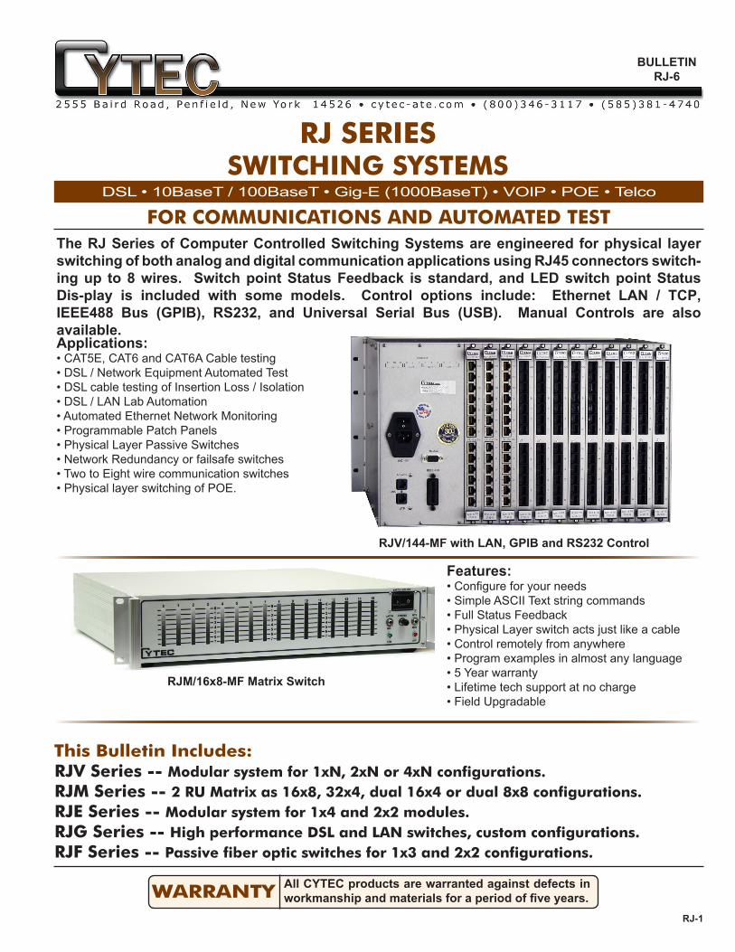
RJM/2(1x4)-4,-8 SWITCH MODULESThese modules are built with high sensitivity two pole Type A Armature Relays which ensures high isolation among signal pairs.
Modules switching from 2 to 8 pins on RJ45 connectors are available and are defined by the corresponding part number suffix.
Each two pole relay switches one pin pair on the RJ45 jacks as defined in the EIA/TIA 568 Specification - that is, Pins 1&2, 3&6, 4&5, 7&8.
Built-in pin jumpers allow the switch module to be config-ured as a single 1x8 Module or as two separate 1x4 module as shown in Fig. 6.
A
B
Jumpers0 1 2 3
4 5 6 7
Fig. 6 RJM/2(1x4) Switch Module
RJM/128 MAINFRAMES
CP8 DISPLAY MODULESOne Display Module is required for each RJM Switch Module. These provide the relay drive control for the switch module and have LEDs that show switch status.
Order the Mainframe according to the needed configuration by using the following part numbers:• RJM/16x8-MF for a 16x8 matrix configuration.• RJM/32x4-MF for a 32x4 matrix configuration.• RJM/2(16x4)-MF for a dual 16x4 matrix configuration.• RJM/2(8x8)-MF for a dual 8x8 matrix configuration.• RJM/4(4x8)-MF for a quad 4x8 matrix configuration.
RJ-5
Switch SpecificationsSPECIFICATION TYPE AContact Rating VA 30Switching Voltage DC 110VSwitching Current DC 1.0 ACarrying Current DC 2.0ABreakdown Voltage DC 750VOperate Time msec 3
Build Larger Systems with a Mesa Controller and Multiple Expansion Chassis
MODULESELECT
01 4 5 76
123456789101112131415
23
0
SWITCH01 4 5 7623 SELECT
I
O
AC IN
MESACONTROL
MODULESELECT
01 4 5 76
123456789101112131415
23
0
SWITCH01 4 5 7623 SELECT
I
O
AC IN
MESACONTROL
RJV
SERI
ES
MODE
L #
RJV/1
2x1-BP
ASS
RJV
SERI
ES
RJV/
12x1
MODE
L #
RJV
SERI
ES
RJV
/6x4
MO
DE
L #
RJV
/6x2
MO
DE
L #
RJV
SERI
ES
NC
C0
NOI
O
0
1
SECT
-0
2
3
SECT
-1
MODU
LE #
AC - IN
MESACONTROL
NC
C1
NO
NC
C0
NO
NC
C1
NO
NC
C0
NO
NC
C1
NO
NC
C0
NO
NC
C1
NO
NC
C0
NO
NC
C1
NO
NC
C0
NO
NC
C1
NO
NC
C0
NO
NC
C1
NO
NC
C0
NO
NC
C1
NO
Primary CtrlSecondary Ctrl0123456789101112131415
IEEE-488
RS-232
LAN
I
O
A/C-In
IEEE-488
RS-232
LAN
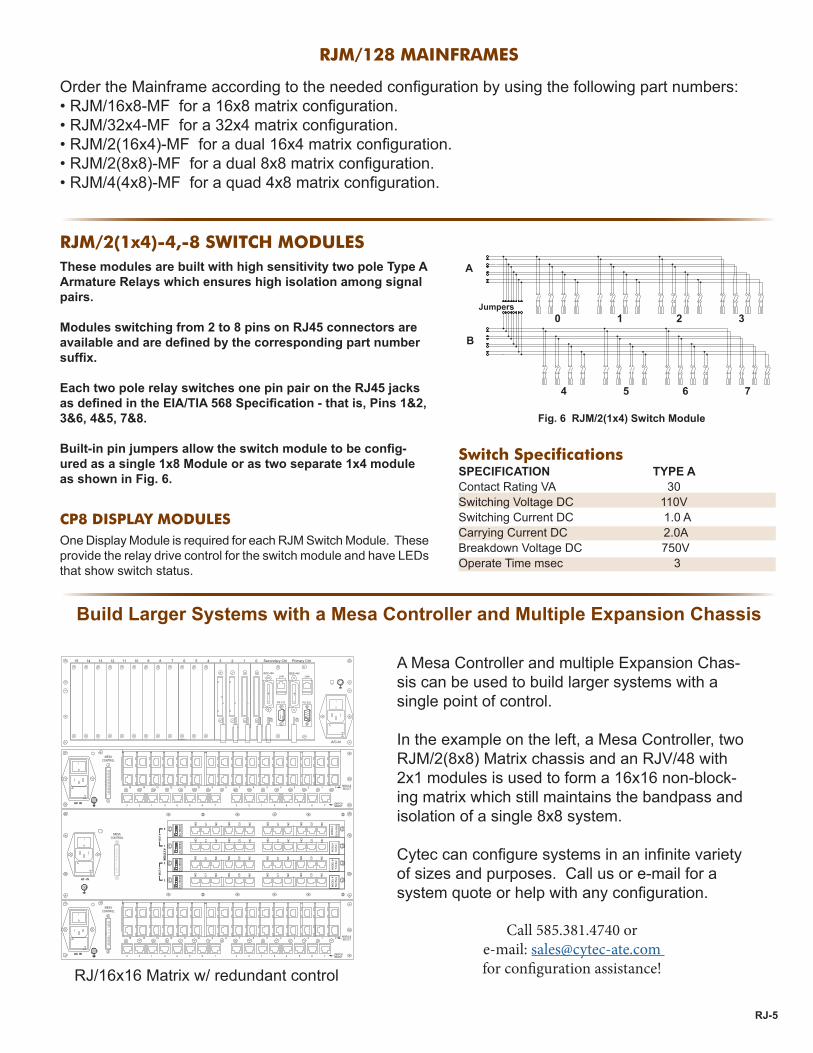
RJ/16x16 Matrix w/ redundant control
A Mesa Controller and multiple Expansion Chas-sis can be used to build larger systems with a single point of control.
In the example on the left, a Mesa Controller, two RJM/2(8x8) Matrix chassis and an RJV/48 with 2x1 modules is used to form a 16x16 non-block-ing matrix which still maintains the bandpass and isolation of a single 8x8 system.
Cytec can configure systems in an infinite variety of sizes and purposes. Call us or e-mail for a system quote or help with any configuration.
Call 585.381.4740 or e-mail: [email protected] for configuration assistance!

RJE SERIES - MULTIPLEXERS (up to 16 individual 1x4) Each RJE chassis holds up to 16 of the RJE/4x1-8 or 16 RJE/2x2-8 Switch Modules as shown in the opposite figure. Each module switches up to eight wires (as four pairs) on RJ45 connectors. These switch modules are designed for demanding high speed networking applications up to Gigabit Eth-ernet speeds.
19" rack mount (483 mm)20" depth (508 mm) 5.25" (3U) height (133 mm)25 lbs. (11.4 kg) max.50 watts max. (110/220 VAC selectable)
Dimensions:
Weight:AC Power:
I
O
0
1
2
3
4
5
6
7
8
9
10
11
12
13
14
15
Mod 0
0
1
2
3
4
5
6
7
8
9
10
11
12
13
14
15
Mod 1
0
1
2
3
4
5
6
7
8
9
10
11
12
13
14
15
Mod 2
0
1
2
3
4
5
6
7
8
9
10
11
12
13
14
15
Mod 3ADDRESSING Rly #
Mod #
0
1
3
2
Com
0123456789101112131415
RS-232
IEEE-488
LAN
RJE Multiplexer - Rear View
Bandpass is DC to 350 MHz, while both NEXT and FEXT are 40 dB or better at 100 MHz.
RJ-6
C 0 1 2 3
1 2
4 3
NC Normally Closed
Position
1 2
4 3
NO Normally
OpenPosition
RJE/4x1-8 Switch Module
RJE/2x2-8 Switch Module
RJE Switch ModulesRJE/1x4-8 Switch ModuleThis module is a 1x4 8 wire tree switch configuration that allows you to select any one of 4 ports and connect them to a common. In the off state, the common port is connected to port 0.
RJE/2x2-8 Switch ModuleThis module is a 2x2 8 wire switch configuration often referred to as a transfer switch or baseball switch. It allows the rerouting of cables on four ports in either of two positions. It is useful for loop back testing, or using to switch between different configurations on other switch mod-ules. It can also be used as a simple Form A, Form B or Form C switch depending on how it is connected.
Switch SpecificationsSPECIFICATION Relays = TYPE A (armature)Contact Rating VA 30Switching Voltage DC 110V Breakdown Voltage DC 750VSwitching Current DC 1.0 A Carrying Current DC 2.0AOperate Time msec 3 msec
RJ45 to SMA Patch PanelThis adapter module allows you to take an RJ45 connection out to the individual wires for testing. The board uses a CAT6A RJ45 connector and Female SMA coax connectors to ensure maxi-mum performance and can be used up to 10G BaseT Ethernet and CAT6A test applications. P/N 99-69-10
Performance: Call or e-mail for specific test data.The module brings out the wires per EIA/TIA 568 Pairs of 1-2, 3-6, 4-5 and 7-8. Allows easy connections to scopes, network analyzers, or test specific switching applications. Buy them as stand alone bench top adapters or we can mount them into rack mount panels with custom labeling.

RJ-7
FOR TECHNICAL ASSISTANCE, PLEASE CONTACT CYTEC AT 800-346-3117 OR VISIT OUR WEBSITE AT cytec-ate.com
RJG SERIES - High Performance DSL Switches Each RJG chassis holds up to 10 of the RJG/8x1-2-RJ45 or a variety of other modules such as coax switches. RJG switch Modules allow high performance testing of DSL or other high speed serial communications signals. Can be provided with adaptors and coax mod-ules for measurements using scopes and net-work analyzers. Has front panel LED indicators for visual status.
19" rack mount (483 mm)20" depth (508 mm) 10.5" (6U) height (266 mm)25 lbs. (11.4 kg) max.50 watts max. (110/220 VAC selectable)
Dimensions:
Weight:AC Power:
I
O
Mod 0Mod 1Mod 2Mod 3Mod 4Mod 5Mod 6Mod 7
A/C - IN
RS-232
LAN
0
1
2
3
C
4
5
6
7
Mod 8Mod 9
IEEE-488
RJG Multiplexer - Rear View
RJG Switch ModulesRJG/1x8-2-RJ45 Switch ModuleThis module is a 1x8 2 wire tree switch con-figuration that allows you to select any one of 8 ports and connect them to a common. In the off state, the 8 ports may be open, terminated to ground or terminated across 100 ohms. The module uses CAT6A connectors for excellent isolation and unused pins on the RJ45 connec-tor are grounded. The module allows for high performance testing of advanced DSL technol-ogy.
0 21 3 4 5 6 7COM
2 2 2 2 2 2 2 2 2
Switch SpecificationsSPECIFICATION TYPE ASwitched Power 1 WattCarry Power 10 WattsSwitching Voltage DC 30VSwitching Current DC 0.5 ACarrying Current DC 1.0 ABreakdown Voltage DC 500 VOperate Time msec 10
RJG/1x8-2-RJ45 Switch Module
Signal SpecificationsImpedance 100 Ohm +/- 2 ohmsBandpass DC to 750 MHz ( -3dB )Isolation > 80 dB to 100 MHzIsolation > 65 dB to 250 MHzReturn Loss / VSWR -25 dB / 1.12:1 to 125 MHzReturn Loss / VSWR -15 dB / 1.50:1 to 300 MHzTerminations Dual 50 ohms to ground or 100 ohms across pair.
Controls
Control Modules
MC/128-TW Manual Controls
The RJ Series Mainframes are computer controlled via Ethernet LAN, IEEE488 and RS232 (standard). USB and Manual Control are optionally available. FPGA Control only on Model 7446.
WARRANTYCYTEC Corp. warrants that all products are free from defects in
material or workmanship for a period of five years.
Thumbwheels and Switches on the front panel select and control up to 128 relays.
MC/2 Manual ControlThis Manual Control Option has a Keypad and LCD Display on the front panel so that the operator can select any relay and verify that the relay has been selected via the display. It is only available for the RJF, RJG & RJV Series.
SOFTWARE HELPFree drivers and/or sample programs are available for mostcommonly available application programming languages in-cluding National Instruments LabView and LabWindows, C, VB.net, Java, Python, TCL, Matlab and Keysight Vee. Others on request.
CYTEC SWITCH SOFTWARECheck out the latest versions of free GUI software on our webpage at: http://cytec-ate.com/supportThe software runs on Windows XP or later. Source code available on request.
Cytec’s newest control module has the three most popular control interface protocols built into one module and is backwards compatible with all previous Cytec control modules.
LAN - 10/100BaseT Ethernet with an RJ45 Connector.The interfaces uses a static IP easily reset by the end user. There are three ports available and all may be used at the same time. Two ports can be set by the end user and one is the default Telnet which may be disabled.
GPIB - IEEE488.2 compliant control module.Commonly used with automated test applications. Works with all GPIB control cards and software including National Instru-ments, Matlab and Keysight. Drivers available upon request.
RS232 - Standard D9 serial port which can be used from com-puter com ports or USB to COM port cables
IF-11 LAN / GPIB / RS232 Control
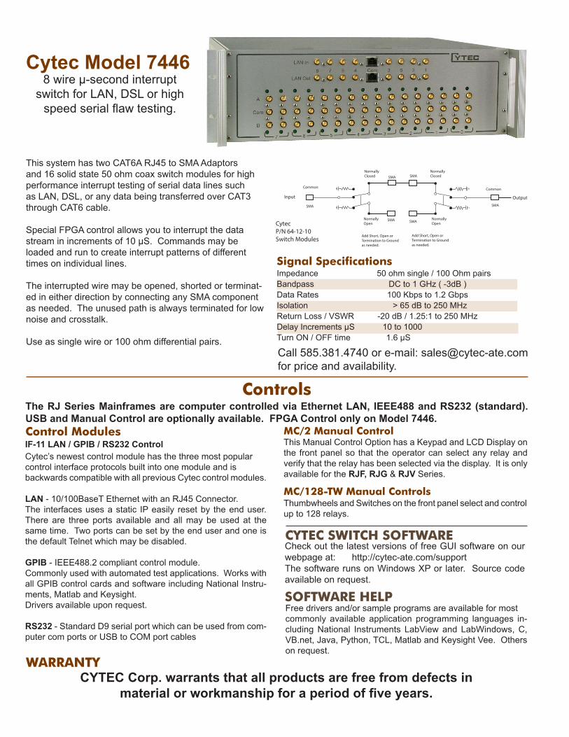
Input Output
Common
Normally Closed
Normally Open
SMA
Add Short, Open or Termination to Ground as needed.
SMA
SMA
Common
Normally Closed
Normally Open
SMA
Add Short, Open or Termination to Ground as needed.
SMA
SMA
Cytec P/N 64-12-10Switch Modules
Cytec Model 74468 wire μ-second interrupt
switch for LAN, DSL or high speed serial flaw testing.
This system has two CAT6A RJ45 to SMA Adaptors and 16 solid state 50 ohm coax switch modules for high performance interrupt testing of serial data lines such as LAN, DSL, or any data being transferred over CAT3 through CAT6 cable.
Special FPGA control allows you to interrupt the data stream in increments of 10 μS. Commands may be loaded and run to create interrupt patterns of different times on individual lines.
The interrupted wire may be opened, shorted or terminat-ed in either direction by connecting any SMA component as needed. The unused path is always terminated for low noise and crosstalk.
Use as single wire or 100 ohm differential pairs.
Signal SpecificationsImpedance 50 ohm single / 100 Ohm pairsBandpass DC to 1 GHz ( -3dB )Data Rates 100 Kbps to 1.2 GbpsIsolation > 65 dB to 250 MHzReturn Loss / VSWR -20 dB / 1.25:1 to 250 MHzDelay Increments μS 10 to 1000Turn ON / OFF time 1.6 μS
Call 585.381.4740 or e-mail: [email protected] for price and availability.

![RJ1 RJ 2 RJ 5L RJ 5R RJ 19 RJ 18 RJ 6 RJ 7 RJ 11 RJ 5R RJ ...Parts]--Jr.pdf · RJ 3 RJ 8 RJ 11 RJ 6 RJ 5R RJ 4 RJ 26 RJ 27 RJ 28 RJ 29 RJ 5L SPECIAL PAWL For clockwise rotation, a](https://static.fdocuments.in/doc/165x107/5f7bfd0580b79229701f388e/rj1-rj-2-rj-5l-rj-5r-rj-19-rj-18-rj-6-rj-7-rj-11-rj-5r-rj-parts-jrpdf-rj.jpg)


