Ring LANs - cs.virginia.edujorg/teaching/cs457/slides/lanp2.pdf · Token Ring LANs • Note: – If...
35
1 © Jörg Liebeherr, 1998,1999 CS457 Ring Local Area Network Ring interface (1-bit buffer) Ring interface To station From station © Jörg Liebeherr, 1998,1999 CS457 Ring LANs • The ring is a series of bit repeaters, each connected by a unidirectional transmission link • All arriving data is copied into a 1-bit buffer and then copied out again (1-bit delay) • Data in the buffer can be modified before transmission • Ring interface can be in one of three states: – Listen State – Transmit State – Bypass State
Transcript of Ring LANs - cs.virginia.edujorg/teaching/cs457/slides/lanp2.pdf · Token Ring LANs • Note: – If...

1
© Jörg Liebeherr, 1998,1999 CS457
Ring Local Area Network
Ring interface(1-bit buffer)
Ring interface
To station From station
© Jörg Liebeherr, 1998,1999 CS457
Ring LANs
• The ring is a series of bit repeaters, each connected by aunidirectional transmission link
• All arriving data is copied into a 1-bit buffer and then copiedout again (1-bit delay)
• Data in the buffer can be modified before transmission• Ring interface can be in one of three states:
– Listen State– Transmit State– Bypass State

2
© Jörg Liebeherr, 1998,1999 CS457
• Listen State: Incoming bits are copied to output with 1-bit delay
• Transmit State: Write data to the ring
To station From station
To station From station
States of the Ring Interface
© Jörg Liebeherr, 1998,1999 CS457
States of the Ring Interface
• Bypass State: Idle station does not incur bit-delay

3
© Jörg Liebeherr, 1998,1999 CS457
Ring LANs
• If a frame has traveled once around the ring it is removed bythe sender
• Ring LANs have a simple acknowledgment scheme:– Each frame has one bit for acknowledgment.– If the destination receives the frame it sets the bit to 1.– Since the sender will see the returning frame, it can tell if
the frame was received correctly.
© Jörg Liebeherr, 1998,1999 CS457
What is the ‘Length’ of a Ring?
• The length of a ring LAN, measured in bits, gives the totalnumber of bits which are can be in transmission on the ring ata time
• Note: Frame size is not limited to the “length” of the ring sinceentire frame may not appear on the ring at one time. Why?
• Bit length = propagation speed · length of ring · data rate ++ No. of stations · bit delay at repeater

4
© Jörg Liebeherr, 1998,1999 CS457
Example|:
• Calculate the length of the following ring LAN:• 3 km ring• 1 Mbps data rate• 5 µs/km propagation speed• 20 stations @ 1 bit delay
• Bit length =
© Jörg Liebeherr, 1998,1999 CS457
Ring LAN
• Advantages:• Can achieve 100 % utilization• No collisions• Can achieve deterministic delay bounds• Can be made efficient at high speeds
• Disadvantages:– Long delays due to bit-delays
• Solution: Bypass state eliminates bit-delay at idle station– Reliability Problems
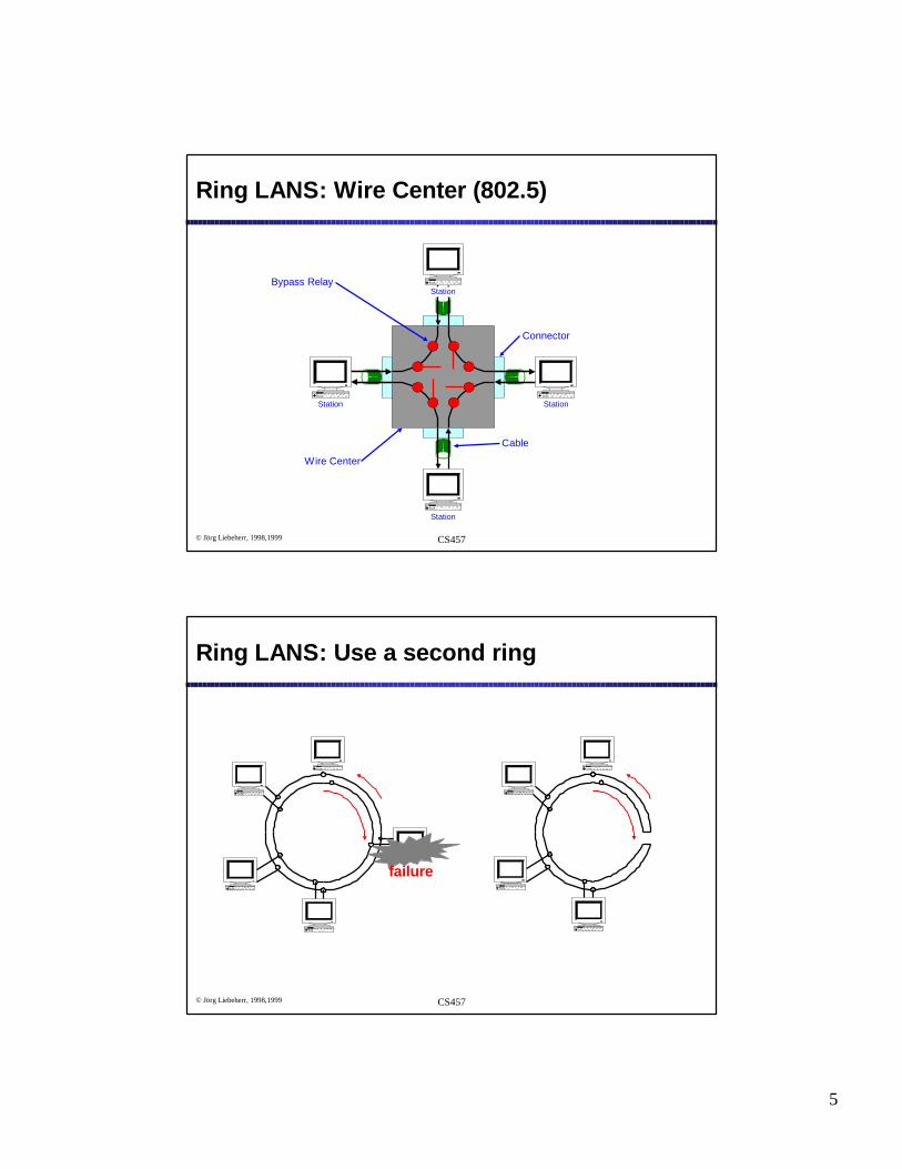
• Solution 1: Use a wire center• Solution 2: Use a second ring (opposite flow)
5
© Jörg Liebeherr, 1998,1999 CS457
Ring LANS: Wire Center (802.5)
Station
Station
Station
Station
Connector
Cable
Bypass Relay
Wire Center
© Jörg Liebeherr, 1998,1999 CS457
Ring LANS: Use a second ring
failure
This is known as a dual-redundant counter-rotating ring

6
© Jörg Liebeherr, 1998,1999 CS457
• Token is a small packetthat rotates around thering
• When all stations are idle,the token is “free” andcirculates around the ring
• Possible Problem: Allstations are idle and in theBypass state. What is theproblem?
Token
A
B
C
D
Token Ring LANS
© Jörg Liebeherr, 1998,1999 CS457
802.5(Token Ring) MAC Protocol
• In order to transmit a station must catch a “free” token
• The station changes the token from “free” to “busy”
• The station transmits its frame immediately following the busytoken
• IF station has completed transmission of the frame AND thebusy token has returned to the station THEN station inserts anew free token into the ring

7
© Jörg Liebeherr, 1998,1999 CS457
Token Ring LANs
• Note:– If the bit length of the ring is less than the packet length,
then the completion of a packet transmission implies returnof busy token
– Only one station can transmit at a time. If a stationreleases a free token, the next station downstream cancapture the token
© Jörg Liebeherr, 1998,1999 CS457
Transmission in a Token Ring
• Sender looks for freetoken
A
B
C
D
Free token

8
© Jörg Liebeherr, 1998,1999 CS457
Transmission in a Token Ring
• Sender changes freetoken to busy tokenand appends data tothe token
A
B
C
D
Busy token
Data
© Jörg Liebeherr, 1998,1999 CS457
Transmission in a Token Ring
A
B
C
D
Busy token
• Receiver recognizesthat it is the destinationof the frame
• Receiver copies frameto station
• Note: Frame alsoreturns to sender
Data

9
© Jörg Liebeherr, 1998,1999 CS457
A
B
C
D
Transmission in a Token Ring
Data
• Receiver recognizesthat it is the destinationof the frame
• Receiver copies frameto station
• Note: Frame alsoreturns to sender
© Jörg Liebeherr, 1998,1999 CS457
Transmission in a Token Ring
A
B
C
D
Data
Free token
• Sender generatesfree token when it isdone transmitting(Note: The busytoken has returned)

10
© Jörg Liebeherr, 1998,1999 CS457
Properties of the 802.5 Token Ring
• No collisions of frames• Full utilization of bandwidth is feasible• Transmission can be regulated by controlling access to token• Recovery protocols is needed if token is not handled properly,
e.g., token is corrupted, station does not change to “free”, etc
© Jörg Liebeherr, 1998,1999 CS457
Token Format / Data Frame Format:
Destinationaddress
Sourceaddress Data Checksum
1 1 1 2 or 6 2 or 6 No Limit 4Bytes
PreambleStart delimiter
Frame control End delimiter
SD AC FC ED FS
Frame status
1 1 1
SD AC ED
Bytes

11
© Jörg Liebeherr, 1998,1999 CS457
IEEE 802.5 Frame Format
• One 3-byte token circulates if all stations are idle.AC = “PPPTMRRR” where
“PPP” Priority fields“RRR” Reservation fields“T” Indicates “Token” or “Data frame”
• SD, ED: Start/End delimiter of a frame• FC: Identifies type of a control frame• FS: Contains address recognized bit (A bit) and
frame copied bit (C bit)– Receiver sets A=1 when frame arrives– Receiver sets C=1 when frame has been copied
© Jörg Liebeherr, 1998,1999 CS457
Priority of Transmission in 802.5
• Eight levels of priorities– Priorities handled by 3-bit priority field and 3-bit reservation
field
– Define:Pm = priority of the message to be transmittedPr = token priority of received tokenRr = reservation priority of received token

12
© Jörg Liebeherr, 1998,1999 CS457
IEEE 802.5 ( Token Ring)
1. A station wishing to transmit a frame with priority Pm must waitfor a free token with Pr ≤ Pm
2. The station can reserve a future priority-Pm token as follows:– If busy token comes by, then set Rr ← Pm (if Rr < Pm)
– If free token comes by, then set Rr ← Pm (if Rr < Pm and Pm < Pr)
© Jörg Liebeherr, 1998,1999 CS457
IEEE 802.5 ( Token Ring)
3. If a station gets a free token, it sets the reservation field to“0”, and leaves the priority field unchanged and transmits
4. After transmission send a free token with• Priority = max (Pr , Rr , Pm)• Reservation = max (Rr , Pm)
5. Station which upgraded the priority level of a token must alsodowngrade the priority (if no one used the token)

13
© Jörg Liebeherr, 1998,1999 CS457
Ring Maintenance
• Token ring selects one station as the monitor station
• Duties of the monitor:– Check that there is a token– Recover ring if it is broken– Detect garbled frames– Make sure the token (24-bit) is shorter than the ring length
© Jörg Liebeherr, 1998,1999 CS457
Terms in IEEE 802.5
• IEEE 802.5 requires to maintain a large number ofcounters
THT: Token Holding Timer (one per station)
Limits the time that a station can transmit (Default 10 ms)
TRR: Time-to-Repeat Timer (one per station)
Limits the time that a station waits for return of own message(Default 2.5 ms)
TVX: Valid Transmission Timer (in monitor station)
Verifies that station which accessed the token actually used it(Default: THT + TRR = 12.5 ms)
TNT: No-Token Timer (one per station)
If expire, a new token is generated(Default: N * (THT + TRR))

14
© Jörg Liebeherr, 1998,1999 CS457
Performance of Token Rings
• Parameters and Assumption:• End-to-end propagation delay a• Packet transmission time 1• Number of stations N
• Assume that each station always has a packet waiting fortransmission
• Note: The ring is used either for data transmission or forpassing the token
© Jörg Liebeherr, 1998,1999 CS457
Performance of Token Rings
• Define:
• T1 = Average time to transmit a frame. Perassumption, T1=1
• T2 = Average time to pass the token
21
1
TTT
OverheadTimeFrameTimeFrame
ThroughputMaximum
+=
+=
=

15
© Jörg Liebeherr, 1998,1999 CS457
NaS
+=
11
NaaS
+= 1
Effect of propagation delay
Effect of propagation delay on throughput:• Case 1: a < 1 (Packet longer than ring)
• T2 = time to pass token to the next station
= a/N• Case 2: a > 1 (Packet shorter than ring)
• Note: Sender finishes transmissionafter T1 = 1, but cannot release thetoken until the token returns
• T1 + T2 = min (1, a) + a/N
© Jörg Liebeherr, 1998,1999 CS457
Performance of Token Rings
• Illustration of Analysis ( a>1 )
Workstation
t0
Workstation
t0+a+1
Workstation
t0+a
Workstation
t0+1

16
© Jörg Liebeherr, 1998,1999 CS457
Performance of Token Rings
• Illustration of Analysis ( a<1 )
Workstation
t0
Workstation
t0+a+1
Workstation
t0+1
Workstation
t0+a
© Jörg Liebeherr, 1998,1999 CS457
Ethernet vs. Token Ring
• Maximum throughput as a function of “a”

17
© Jörg Liebeherr, 1998,1999 CS457
Ethernet vs. Token Ring
• Maximum throughput as a function of “N”
© Jörg Liebeherr, 1998,1999 CS457
FDDI
• Some Facts:• FDDI = Fiber Distributed Data Interface• FDDI is a high-speed token ring• Fiber-optic (dual redundant counter rotating) ring LAN• Multimode fiber• Standardized by ANSI and ISO X3T9.5 committee• 100 Mbps data rate• Maximum frame size is 4500 bytes• Allows up to 1000 connected stations• Maximum ring circumference 200 km

18
© Jörg Liebeherr, 1998,1999 CS457
FDDI
• FDDI distinguishes 4 Service Classes:
– Asynchronous
– Synchronous
– Immediate (for monitor and control)
– Isochronous (only in FDDI-II)
© Jörg Liebeherr, 1998,1999 CS457
FDDI - Protocol Architecture
LLC (IEEE 802.2)Logical Link Control
SMT
initialization
performancemonitoring
maintenance
allocation ofbandwidth
configuration
MACring accessdata transfer
PHYcoding / decoding
transmit / receive datastream
PMDConversion to optical signal
SMT: Station Management
MAC: Medium Access Control
PHY: Physical Layer Protocol
PMD: Physical Layer Medium Dependent

19
© Jörg Liebeherr, 1998,1999 CS457
Dual Redundant Counter Rotating Ring
• Second ring adds a certain level of fault tolerance
© Jörg Liebeherr, 1998,1999 CS457
SMT
LLC LLC
MAC MAC
PHY PHY
BYPASS
To Next StationFrom Last Station
Station Types - Class A Station
• Two PHY (and one or two MAC) entities• Connects to another Class A station or to a concentrator

20
© Jörg Liebeherr, 1998,1999 CS457
Station Types - Class B Station
• Class B station has one PHY (and one MAC) entity
• Connects to a concentrator
SMT
LLC
MAC
PHY
To Concentrator
© Jörg Liebeherr, 1998,1999 CS457
Station Types - Concentrator
• Connects Class A and Class B stations into one of thecounter rotating rings.
• Concentrator can bypass failing stations.
LLC
MAC
PHY
PHY
BYPASS
To Next StationFrom Last Station
PHYPHY
SMTPHY
To Class B Stations

21
© Jörg Liebeherr, 1998,1999 CS457
Topology Example
P PP
P P
M
P
M
P
M
P
M
P
P P
P
P P
M M
Node 3
Node 4Node 5Node 6
P=PHYM=MAC
© Jörg Liebeherr, 1998,1999 CS457
FDDI Media Access Control
• FDDI uses a Token Ring Protocol, similar to 802.5• Differences of FDDI and 802.5:
– To release a token, a station does not need to wait until the tokencomes back after a transmission. The token is released right after theend of transmission
– In FDDI, multiple frames can be attached to the token
– FDDI has a different priority scheme

22
© Jörg Liebeherr, 1998,1999 CS457
FDDI Token Ring Protocol
1. A awaits token
2. A seizes token, beginstransmitting frame F1addressed to C
A
B
A
B
T
A
F1
A
B
B
© Jörg Liebeherr, 1998,1999 CS457
FDDI Token Ring Protocol
3. A appends token to end oftransmission
4. C copies frames F1 as itgoes by
A
B
A
B
C
D
F1C
D
F1
T
T
A
B
A
B

23
© Jörg Liebeherr, 1998,1999 CS457
FDDI Token Ring Protocol
5. C continues to copy F1; Bseizes token and transmitsframe F2 addressed to D
6. B emits token; D copies F2;A absorbs F1
A
B
A
B
C
D
F1
C
D
F1
T
A
B
A
B
F2
F2
© Jörg Liebeherr, 1998,1999 CS457
FDDI Token Ring Protocol
7. A lets F2 and token pass; Babsorbs F2
8. B lets token pass
A
B
A
B
C
D
C
D
T
B
A
B
F2
T

24
© Jörg Liebeherr, 1998,1999 CS457
Preamble SD FC DA SA Info FCS ED FS
Bits 64 8 8 16 or 48 >=0 32 4 12
General Frame Format
Preamble SD FC
Bits 64 8 8
Token Frame Format
Frame and Token Format
• SD Starting Delimiter• FC Frame Control (type of frame)• DA Destination Address• SA Source Address• FCS Frame Check Sequence (CRC)• ED End Delimiter• FS Frame Status• Total Frame length ≤ 4500bytes
© Jörg Liebeherr, 1998,1999 CS457
Timed Token Protocol
• FDDI has a timed token protocol which determines how longa station can transmit
• Each station has timers to measure the time elapsed since atoken was last received
• TTRT Target Token Rotation Time– Value of TTRT is negotiated during initialization (default is 8 ms)– Set to the maximum desired rotation time

25
© Jörg Liebeherr, 1998,1999 CS457
Parameters of Timed Token Protocol
• Station Parameters:• TRT Token Rotation Time
• Time of the last rotation of the token.• If TRT < TTRT, then token is “early”, asynchronous
traffic can be transmitted• If TRT > TTRT then token is “late”, asynchronous traffic
cannot be transmitted.• THT Token Holding Time
• Controls the time that a station may transmitasynchronous traffic.
• fi Percentage of the TTRT that is allocated forsynchronous traffic at station i.
© Jörg Liebeherr, 1998,1999 CS457
Timed Token Protocol
• If a station receives the token it setsTHT:= TRTTRT:= TTRTEnable TRT (i.e., start the timer)
• If the station has synchronous frames are waiting the transmitsynchronous traffic for up to time TTRT • fi (with Σi <1)
• If the station has asynchronous trafficenable THTwhile THT > 0 transmit asynchronous traffic.

26
© Jörg Liebeherr, 1998,1999 CS457
Timed Token Protocol
• Note:
– Transmission is not interrupted if THT expiresduring a transmission.
– If a station does not utilize its maximumtransmission time (i.e., THT), the next station canuse it.
© Jörg Liebeherr, 1998,1999 CS457
Analysis of FDDI
• Annalysis of– Synchronous traffic– Asynchronous trafic
• Synchronous Traffic:
– Recall that each station can transmit synchronous trafficfor up to time TTRT • fi (with Σi fi ≤ 1)
– If Σi fi = 1, the maximum throughput of synchronous traffic is100%.
– One can show that the maximum delay until a frame iscompletely transmitted is:
Maximum Access Delay ≤ 2 • TTRT

27
© Jörg Liebeherr, 1998,1999 CS457
Analysis of FDDI
Station1 Station1 Station3
D
T-D
3T-D
• Asynchronous Traffic
• Parameters:
D Ring latency
n Number of activesessions (all
heavily loaded)T Value of TTRT
• Assumption:– No synchronous
traffic
© Jörg Liebeherr, 1998,1999 CS457
• From the Example we see:• Cycle in a system has a length of: nT + D• Time in a cycle used for transmission: n(T - D)
• We obtain for the maximum throughput for asynchronoustraffic is:
• ... and the maximum access delay for asynchronous traffic:
DnTD)-n(T
Throughput Max.+
=
2D1)-T(n Delay Access .Max +=
Analysis of FDDI

28
© Jörg Liebeherr, 1998,1999 CS457
Analysis of FDDI
• Numerical Example– Number of stations: 16– Length of fiber: 200 km– Speed of Signal 5 ms/km– Delay per station: 1 ms/station– TTRT: 5 msec
• Ring Latency D = (20 km) × (5 msec/km) + + (16 stations) × 1 msec/station
= 0.12 ms.
© Jörg Liebeherr, 1998,1999 CS457
75.24ms0.1221)-5(16
Delay Access .%5.97
12.05160.12)-16(5
Throughput Max.
=×+=
==
+×=
=
Max
Analysis of FDDI
Synchronous Traffic • Asynchronous Traffic
10ms5ms 2
Delay Access .%100
Throughput Max.
=⋅=
==
=
Max

29
© Jörg Liebeherr, 1998,1999 CS457
Numerical Results
• We show plots for 3 different FDDI networks.
– “Typical” FDDI:– 20 stations (single MAC)– 4 km ring
– “Big” FDDI:– 100 stations (single MAC)– 200 km ring
– “Largest” FDDI:– 500 stations (dual MAC)– 200 km ring
© Jörg Liebeherr, 1998,1999 CS457
Throughput vs. TTRT

30
© Jörg Liebeherr, 1998,1999 CS457
Maximum Access Delay vs. TTRT
© Jörg Liebeherr, 1998,1999 CS457
Supplemental Material (Token Bus )

31
© Jörg Liebeherr, 1998,1999 CS457
IEEE 802.4 (Token Bus)
• Problems with 802.3:• Collisions of frames can lead to unpredictable delays• In some real-time scenarios, collisions and
unpredictable delays can be catastrophic
• Solution via Token Bus:• A control packet (Token) regulates access to the bus• A station must have the token in order to transmit• A station can hold the token only for a limited time• The token is passed among the stations in a cyclic order
This structures the bus as a logical ring
© Jörg Liebeherr, 1998,1999 CS457
Token Bus
A
B
C
D
Succ=DPred=C
Succ=APred=B
Succ=CPred=D
Succ=BPred=A
IEEE 802.4 (Token Bus)
• Stations form a logical ring• Each station knows its successor and predecessor in the ring

32
© Jörg Liebeherr, 1998,1999 CS457
Feature of Token Bus
• Bandwidth is 1, 5, or 10 Mbps
• The token bus MAC protocol is very complex
• Typically, token bus is free of collisions
• Defines priority transmissions and can offer boundedtransmission delays
© Jörg Liebeherr, 1998,1999 CS457
IEEE 802.4 (Token Bus)
• 802.4 requires each station to implement the followingmanagement functions:
– Ring Initialization– Addition to ring– Deletion from ring– Fault management

33
© Jörg Liebeherr, 1998,1999 CS457
Adding a Station to the Token Bus
• Each node periodically sends a solicit successor packet whichinvites nodes with an address between itself and the nextnode to join the ring
• Sending node waits for response for one round trip• One of the following three cases apply
(1) No Response:– Pass token
(2) Response from one node:– Reset successor node– Pass token to new successor node
(3) Response from more than one node:– Collision has occurred– Node tries to resolve contention
© Jörg Liebeherr, 1998,1999 CS457
Add a station to the Token Bus
• Assume: Response from more than one node has resulted ina collision.– Station sends a resolve contention packet and waits for four windows
(window = 1 round trip time) for a response:– In window 1, stations with address prefix “00” can reply– In window 2, stations with address prefix “01” can reply– In window 3, stations with address prefix “10” can reply– In window 4, stations with address prefix “11” can reply
– If there is a another collision, procedure is repeated for the second pairof bits. Only the nodes which replied earlier can join the next round
– First successful reply joins the ring

34
© Jörg Liebeherr, 1998,1999 CS457
IEEE 802.4 (Token Bus)
• Four priority levels:• Levels 6, 4, 2, 0• Priority 6 is the highest level
• Token Holding Time (THT):• Maximum time a node can hold a token
• Token Rotation Time for class i (TRTi):• Maximum time of a full token circulation at which priority
i transmissions are still permitted
© Jörg Liebeherr, 1998,1999 CS457
Token Bus Transmission Rules
• Each station can transmit class 6 data for a time THT• For i= 4, 2, 0:
– Transmit class i traffic if all traffic from class i+2 or higher istransmitted
– and the time of the last token circulation (including thetransmission time of higher priority packets during thecurrent holding of the token) is less than TRTi.

35
© Jörg Liebeherr, 1998,1999 CS457
Token Bus Priority Scheme
Class 6 ToSend ?
THT Timerexpired ? Send Frame
Y N
UseToken
Class 4 ToSend ?
TRT4 Timerexpired ? Send Frame
Y N
Class 2 ToSend ?
TRT2 Timerexpired ? Send Frame
Y N
Class 0 ToSend ?
TRT0 Timerexpired ? Send Frame
Y N
N
N
N
Y
Y
Y
More DataTo Send ?
Want ToStay inRing?
Send Set-SuccessorFrame to
PredecessorN N
NY
UseToken
Y Y