Rigid Frames - Compression &...
12
ARCH 614 Note Set 11.1 S2014abn 1 Rigid Frames - Compression & Buckling Notation: A = name for area d = name for depth E = modulus of elasticity or Young’s modulus f a = axial stress f b = bending stress f z = stress in the x direction F a = allowable axial stress F b = allowable bending stress F x = force component in the x direction F y = force component in the y direction FBD = free body diagram G = relative stiffness of columns to beams in a rigid connection, as is I = moment of inertia with respect to neutral axis bending k = effective length factor for columns b = length of beam in rigid joint c = length of column in rigid joint L = name for length L e = effective length that can buckle for column design, as is e M = internal bending moment = name for a moment vector P = name for axial force vector, as is P’ P crit = critical buckling load in column calculations, as is P critical , P cr r = radius of gyration V = internal shear force y = vertical distance = displacement due to bending = pi (180) = summation symbol = relative stiffness of columns to beams in a rigid connection, as is G Rigid Frames Rigid frames are identified by the lack of pinned joints within the frame. The joints are rigid and resist rotation. They may be supported by pins or fixed supports. They are typically statically indeterminate. Frames are useful to resist lateral loads. Frame members will see shear bending axial forces and behave like beam-columns.
Transcript of Rigid Frames - Compression &...

ARCH 614 Note Set 11.1 S2014abn
1
Rigid Frames -
Compression & Buckling
Notation:
A = name for area
d = name for depth
E = modulus of elasticity or Young’s
modulus
fa = axial stress
fb = bending stress
fz = stress in the x direction
Fa = allowable axial stress
Fb = allowable bending stress
Fx = force component in the x direction
Fy = force component in the y direction
FBD = free body diagram
G = relative stiffness of columns to
beams in a rigid connection, as is
I = moment of inertia with respect to
neutral axis bending
k = effective length factor for columns
b = length of beam in rigid joint
c = length of column in rigid joint
L = name for length
Le = effective length that can buckle for
column design, as is e
M = internal bending moment
= name for a moment vector
P = name for axial force vector, as is P’
Pcrit = critical buckling load in column
calculations, as is Pcritical, Pcr
r = radius of gyration
V = internal shear force
y = vertical distance
= displacement due to bending
= pi (180)
= summation symbol
= relative stiffness of columns to
beams in a rigid connection, as is G
Rigid Frames
Rigid frames are identified by the lack of pinned
joints within the frame. The joints are rigid and
resist rotation. They may be supported by pins or
fixed supports. They are typically statically
indeterminate.
Frames are useful to resist lateral loads.
Frame members will see
shear
bending
axial forces
and behave like beam-columns.

ARCH 614 Note Set 11.1 S2014abn
2
Behavior
The relation between the joints has to be maintained, but the whole joint can
rotate. The amount of rotation and distribution of moment depends on the
stiffness (EI/L) of the members in the joint.
End restraints on columns reduce the effective length, allowing columns to be
more slender. Because of the rigid joints, deflections and moments in beams are
reduced as well.
Frames are sensitive to settlement because it induces strains and changes the stress distribution.
Types
Gabled – has a peak
Portal – resembles a door. Multi-story, multiple bay portal
frames are commonly used for commercial and industrial
construction. The floor behavior is similar to that of
continuous beams.
Staggered Truss – Full story trusses are staggered through the
frame bays, allowing larger clear stories.
Connections
Steel – Flanges of members are fully attached to
the flanges of the other member. This can be
done with welding, or bolted plates.
Reinforced Concrete – Joints are monolithic with
continuous reinforcement for bending. Shear
is resisted with stirrups and ties.
Braced Frames
Braced frames have beams and columns that are “pin” connected with bracing to resist lateral
loads.
Staggered Truss

ARCH 614 Note Set 11.1 S2014abn
3
Types of Bracing
knee-bracing
diagonal (including eccentric)
X
K or chevron
shear walls – which resist
lateral forces in the plane of
the wall
Compression Members - Columns
Including strength (stresses) and servicability (including
deflections), another requirement is that the structure
or structural member be stable.
Stability is the ability of the structure to support a
specified load without undergoing unacceptable (or
sudden) deformations.
A column loaded centrically can experience unstable
equilibrium, called buckling, because of how tall and
slender they are. This instability is sudden and not
good.
Buckling can occur in sheets (like my “memory metal”
cookie sheet), pressure vessels or slender (narrow) beams not braced laterally.
Buckling can be thought of with the loads and motion of a column
having a stiff spring at mid-height. There exists a load where the spring
can’t resist the moment in it any longer.
Short (stubby) columns will experience crushing before buckling.
diagonal X
shear walls K (chevron)
ARCH 614 Note Set 11.1 S2014abn
4
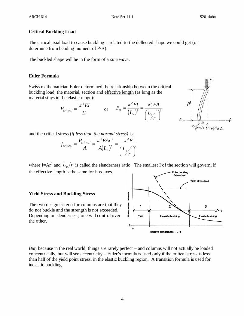
Critical Buckling Load
The critical axial load to cause buckling is related to the deflected shape we could get (or
determine from bending moment of P·).
The buckled shape will be in the form of a sine wave.
Euler Formula
Swiss mathematician Euler determined the relationship between the critical
buckling load, the material, section and effective length (as long as the
material stays in the elastic range):
2
2
L
EIPcritical
or
2
2
2
2
rL
EAπ
L
EIπP
ee
cr
and the critical stress (if less than the normal stress) is:
2
2
2
22
rL
E
LA
EAr
A
Pf
ee
criticalcritical
where I=Ar2 and rLe is called the slenderness ratio. The smallest I of the section will govern, if
the effective length is the same for box axes.
Yield Stress and Buckling Stress
The two design criteria for columns are that they
do not buckle and the strength is not exceeded.
Depending on slenderness, one will control over
the other.
But, because in the real world, things are rarely perfect – and columns will not actually be loaded
concentrically, but will see eccentricity – Euler’s formula is used only if the critical stress is less
than half of the yield point stress, in the elastic buckling region. A transition formula is used for
inelastic buckling.

ARCH 614 Note Set 11.1 S2014abn
5
Effective Length and Bracing
Depending on the end support conditions for a column, the effective length can be found from the
deflected shape (elastic equations). If a very long column is braced intermittently along its length,
the column length that will buckle can be determined. The effective length can be found by
multiplying the column length by an effective length factor, K. LKLe

ARCH 614 Note Set 11.1 S2014abn
6
Bending in Columns
Bending can occur in column like members when there are transverse loads such as wind and
seismic loads, when the column is in a frame, or when the column load does not go through the
axes. This situation is referred to as eccentric loading and the moment is of size P x e.
e P
Wind Load Left Tension Left
T
C
T
C
Seismic Load Left Tension Left
T
C
Eccentric Load Left Tension Left
Wind Load Left Braced at Top
C T

ARCH 614 Note Set 11.1 S2014abn
7
P- (delta) Effect
The bending moment on a column will produce a lateral deflection. Because
there is an axial load P on the column, there will be an addition moment
produced of the size P x , which in turn will cause more deflection, increasing
the moment, etc.. This non-linear increase in moment is called the P- effect.
Design methods usually take this into account with magnification factors.
Combined Stresses
Within the elastic range (linear stresses) we can superposition or add up the normal and bending
stresses (where M can be from Pe or calculated):
The resulting stress distribution is still linear. And the n.a. can move (if there is one)!
Interaction Design
Because there are combined stresses, we can’t just compare the axial stress to a limit axial stress
or a bending stress to a limit bending stress. We use a limit called the interaction diagram. The
diagram can be simplified as a straight line from the ratio of axial stress to allowable stress= 1 (no
bending) to the ratio of bending stress to allowable stress = 1 (no axial load).
The interaction diagram can be more sophisticated (represented
by a curve instead of a straight line). These types of diagrams
take the effect of the bending moment increasing because the
beam deflects. This is called the P- (P-delta) effect.
af bf xf
I
My
A
Pfff bax
af bf xf
1
1
a
a
F
f
b
b
F
f
ARCH 614 Note Set 11.1 S2014abn
8
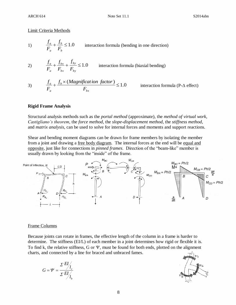
Limit Criteria Methods
1) 0.1b
b
a
a
F
f
F
f interaction formula (bending in one direction)
2) 0.1by
by
bx
bx
a
a
F
f
F
f
F
f interaction formula (biaxial bending)
3) 0.1)(
bx
b
a
a
F
factorionMagnificatf
F
f interaction formula (P- effect)
Rigid Frame Analysis
Structural analysis methods such as the portal method (approximate), the method of virtual work,
Castigliano’s theorem, the force method, the slope-displacement method, the stiffness method,
and matrix analysis, can be used to solve for internal forces and moments and support reactions.
Shear and bending moment diagrams can be drawn for frame members by isolating the member
from a joint and drawing a free body diagram. The internal forces at the end will be equal and
opposite, just like for connections in pinned frames. Direction of the “beam-like” member is
usually drawn by looking from the “inside” of the frame.
Frame Columns
Because joints can rotate in frames, the effective length of the column in a frame is harder to
determine. The stiffness (EI/L) of each member in a joint determines how rigid or flexible it is.
To find k, the relative stiffness, G or , must be found for both ends, plotted on the alignment
charts, and connected by a line for braced and unbraced fames.
b
c
lEI
lEI
G
M+
M+ M+
P

ARCH 614 Note Set 11.1 S2014abn
9
where
E = modulus of elasticity for a member
I = moment of inertia of for a member
lc = length of the column from center to center
lb = length of the beam from center to center
For pinned connections we typically use a value of 10 for .
For fixed connections we typically use a value of 1 for .
Braced – non-sway frame Unbraced – sway frame

ARCH 614 Note Set 11.1 S2014abn
10
Lateral Buckling in Beams
With compression stresses in the top of a beam, a sudden “popping” or buckling can happen even
at low stresses. In order to prevent it, we need to brace it along the top, or laterally brace it, or
provide a bigger Iy.
Torsional buckling can result with simultaneous twisting and bending, which can be a problem
with thin walled, non-symmetric sections.
Example 1 (pg 152)
+ V
+ V
+ V
+ M
+ M
+ M
23.5.
ARCH 614 Note Set 11.1 S2014abn
11
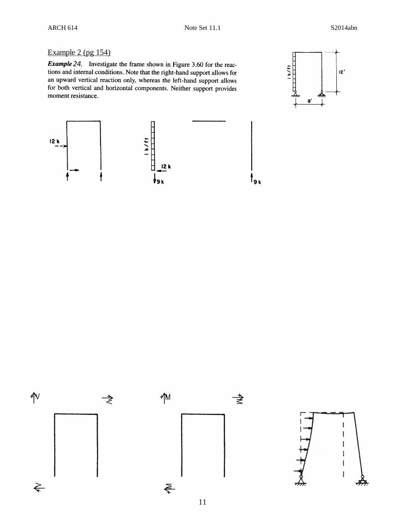
Example 2 (pg 154)
+ V
+ V
+ V
+ M
+ M
+ M
24.5.

ARCH 614 Note Set 11.1 S2014abn
12
Example 3
Find the column effective lengths for a steel frame with 12 ft columns, a
15 ft beam when the support connections are pins for a) when it is
braced and b) when it is allowed to sway. The relative stiffness of the
beam is twice that of the columns (2I).
12 f
t
15 ft
I I
2I