RIGblaster Advantage - West Mountain Radio
34
www.westmountainradio.com 1020 Spring City Drive Waukesha, WI 53186 262-522-6503 [email protected] ©2018 West Mountain Radio, All rights reserved. All trademarks are the property of their respective owners. RIGblaster Advantage
Transcript of RIGblaster Advantage - West Mountain Radio

www.westmountainradio.com1020 Spring City DriveWaukesha, WI 53186
©2018 West Mountain Radio, All rights reserved. All trademarks are the property of their respective owners.
RIGblasterAdvantage

Table of ContentsIntroduction About the RIGblaster Advantage . . . . . . . . . . . . . . . . . . . . 3 Package Contents . . . . . . . . . . . . . . . . . . . . . . . . . . . . . . . 4 About the RIGblaster DVD . . . . . . . . . . . . . . . . . . . . . . . . 4 Digital-Mode Operating . . . . . . . . . . . . . . . . . . . . . . . . . . . 4
Controls, Connections and Features Choosing the Correct ISC . . . . . . . . . . . . . . . . . . . . . . . . . 7 Software Driver Installation . . . . . . . . . . . . . . . . . . . . . . . . 8 Windows, Linux & Mac Drivers . . . . . . . . . . . . . . . . . . . . . 8 How to Renumber the RIGblaster Advantage COM port . . 11 Transceiver Connections . . . . . . . . . . . . . . . . . . . . . . . . . . 12 Required Connections . . . . . . . . . . . . . . . . . . . . . . . . . . . . 12 Optional Connections . . . . . . . . . . . . . . . . . . . . . . . . . . . . 13
RIGblaster Settings Audio Levels . . . . . . . . . . . . . . . . . . . . . . . . . . . . . . . . . . . 13 PTT (Keying your radio) . . . . . . . . . . . . . . . . . . . . . . . . . . 15 Morse (CW) Operation . . . . . . . . . . . . . . . . . . . . . . . . . . . 16 RTTY (FSK) Operation . . . . . . . . . . . . . . . . . . . . . . . . . . . 16 CAT . . . . . . . . . . . . . . . . . . . . . . . . . . . . . . . . . . . . . . . . . . 17Transceiver Settings Operation Mode . . . . . . . . . . . . . . . . . . . . . . . . . . . . . . . . . 18 Recieve Settings . . . . . . . . . . . . . . . . . . . . . . . . . . . . . . . . 19 Transmit Settings . . . . . . . . . . . . . . . . . . . . . . . . . . . . . . . . 19
Reference RIGblaster Advantage Connection Diagrams . . . . . . . . . . 20 Icom CI-V CAT Cable Schematic . . . . . . . . . . . . . . . . . . . 20 ISC & Jumper Wiring . . . . . . . . . . . . . . . . . . . . . . . . . . . . . 21 Using the RIGblaster Advantage as a Microphone Patch Box . . 25 Using the West Mountain Radio COM Port Splitter . . . . . . 26 P2 Jumper . . . . . . . . . . . . . . . . . . . . . . . . . . . . . . . . . . . . . 26 Digital-Modes, Software and Frequencies . . . . . . . . . . . . 27 Troubleshooting . . . . . . . . . . . . . . . . . . . . . . . . . . . . . . . . . 28 Radio Hook-up Diagrams . . . . . . . . . . . . . . . . . . . . . . . . . 30
RIGblaster Advantage Software ConfigurationDetails for configuring the Advantage with many popular software
program is available in a PDF may be downloaded from the • RIGblaster Soundcard Collection DVD• Online at: www.westmountainradio.com/RB_SW_Config

3West Mountain Radio Operating Manual
INTRODUCTION
About The RIGblaster Advantage We understand you have a choice when buying Amateur Radio products and we would like to take a moment to thank you for choosing West Mountain Radio. The RIGblaster Advantage has been designed with you, the digital-mode operator in mind. It has many outstanding features which will at the same time enhance and simplify your operating. Some of the features of the RIGblaster Advantage which put it ahead of the competition include;
•COM port push-to-talk (PTT) keying. •A high-quality built-in USB sound card with level controls (both RX &
TX) on the front panel.•Pre-wired Instant Setup Connectors – no more complex jumper wiring!•Rig-control (CAT/CI-V).* • FSK jack for operating FSK RTTY.**•CW keying jack for operating Morse Code.•Digital VOX with adjustable delay.•Separate audio jacks for received and transmitted audio.• Foot-switch PTT input.•USB virtual serial port with RS-232C externalization• TX inhibit switch.
Connection to your computer is made very simple with the supplied USB cable. We will go into connecting up your RIGblaster Advantage in the first chapter so do not hook it up right away.
Please read through this manual first (especially the driver installation section) and you will find the RIGblaster Advantage will provide you with many years of reliable service and enjoyment.
* Rig control is only available on certain transceivers.** FSK requires the transceiver to have a dedicated RTTY mode, an optional FSK cable and the software must support serial FSK.
INTR
OD
UC
TION

4West Mountain Radio Operating Manual
Package ContentsThe following is a list of the contents for the RIGblaster Advantage. Verify that all the following items were included:
• RIGblaster Advantage Unit• User Manual• 7 - Instant Setup Connectors• 8 - Single Pin White Jumpers• 5 - Mini Blue Shunt Jumpers• 4 - #6 Black Metal Screws (*for cover)• 4 - Adhesive Pads and Rubber Feet• 1 - Microphone Cable (RJ-45 to 8-Pin Screw-On• 1 - 1/8” Stereo Mini Plug Cable• 1 - USB (A/B) Cable• 1 - DVD of RIGblaster Software Collection*The RIGblaster Advantage cover is loose so you may easily remove it to install jumpers.
About the RIGblaster DVD The supplied DVD is mostly a collection of various digital-mode software programs for use with sound card interfaces like the RIGblaster Advantage.
The programs contained on the DVD were not written by West Mountain Radio. Some are completely free while others are commercial. A majority of the software has been tested our products. Amateur radio software is constantly evolving and we encourage you to visit the various authors websites to check for updates for software you wish to use.
Instructions and tips for Software Configuration with the Advantage can be found in the PDF file on this DVD: RIGblaster Advantage Software Configuration.
A list of website addresses for the software on this DVD and the PDF aforementioned can be accessed this page from: http://www.westmountainradio.com/content.php?page=links
Introduction To Digital-Mode OperatingMost modern digital-modes can be operated on the RIGblaster Advantage. Some familiar modes may be PSK31, JT65 & RTTY and are commonly heard on the bands.
If tuned to 14.070MHz (usb) one may hear multiple PSK31 QSOs taking place. Moving up through 14.073MHz one may hear the tones of the MFSK modes such as Olivia, Contestia, Thor and MFSK-16 or possibly the “cricket-like” chirping of Hellschreiber (aka “Feld Hell”).

5West Mountain Radio Operating Manual
When tuned to 14.074MHz, one will be engulfed by the sound of FT8 signals. FT8 is the most popular ham radio mode in use today. It is a narrow band mode, so there are multiple QSOs taking place simultaneously all in a (roughly) 3KHz slice of spectrum. Tuning up through 14.076MHz, the sounds of JT65-A can be heard. However, JT65-A use is declining in usage in favor of FT-8.
The region of 14.080-14.090MHz is almost exclusively radioteletype (RTTY). This segment does not really come to life except in contests or when a DX station is spotted. Continue to tune upwards to 14.097MHz to find most 20m WSPR operation.
Above 14.105MHz lsb is an automatic mode sub-band where one may encounter Packet Radio chat network and numerous Winlink 2000 stations running Pactor, WinMOR, and VARA. On 14.109MHz ALE signals can often be heard.
14.230MHz (usb) yields a very active SSTV (Slow Scan TV) frequency. This is traditional analog SSTV, but can be easily operated with a RIGblaster. Another 3KHz up is the main band of digital SSTV enthusiasts. 14.236MHz is currently popular with the digital voice experimenters using the FreeDV digital voice software.
Note, there are some modes in use that cannot be transmitted with the RIGblaster Advantage (nor any sound-card based interface). These are the ARQ modes such as Pactor and AMTOR which require very precise timing cycles that Windows and other non real-time operating systems are unable to deliver. AMTOR is seldom heard currently, but Pactor is commonly employed for mail messaging using the Winlink 2000 system. However, there are equivalent (and sometimes better) sound-card based modes like WinMOR and VARA which can be used for mail/e-mail messaging with the RIGblaster Advantage and the Winlink 2000 system.
Many digital modes will work far down into the noise level, so it is not uncommon to see copy on the screen, even when it is difficult to hear the signal on a speaker. This also implies it is not necessary to run high power levels during normal conditions. Most digital modes will only need 20-40W PEP output. Running at close to maximum output on the radio is often self-defeating. This may cause a spread-out badly distorted signal (think QRM) and may even damage the rig on long overs, as many transceivers are not designed to run high mean power transmissions for extended periods.
The back of this manual is a simple chart of digital modes, software and frequencies to try. These are suggestions, but may be of assistance in

6West Mountain Radio Operating Manual
Controls, Connections And Features
Mic
roph
one
outp
ut fo
r 8 p
in
roun
d m
ic:u
sed
with
cab
le
(Mic
inpu
t with
RJ4
5 co
nnec
-to
r rad
io
PTT
in/o
ut R
CA
Con
nect
or (u
sed
with
foot
-sw
itch
or o
ther
PTT
sw
itch
or c
onne
ctio
n.
Audi
o lin
e in
put (
outg
oing
aud
io
from
you
r rad
io c
onne
cts
here
Rad
io tr
ansm
itted
aud
io (a
llow
s yo
u to
mon
itor a
udio
rece
ived
by
radi
o)C
ompu
ter t
rans
mitt
ed a
udio
allo
ws
you
to m
onito
r tra
nsit
audi
o fro
m P
CC
W/F
SK k
eyin
g ou
tput
(con
-ne
cts
to ra
dio
keyi
ng in
put
CAT
RIG
Con
trol a
t RS2
32 L
evel
s
CAT
/CI-V
rig
cont
rol (
Con
nect
s to
ra
dio
with
acc
esso
ry c
able
)
USB
to in
terfa
ce (R
ead
driv
er
inst
all b
efor
e co
nnec
ting.
PTT
Softw
are
Con
fi g C
OM
: RTS
Con
trol
PTT
DTG
R C
ontro
ls C
W/F
SK o
ff : c
om-
pute
r can
nev
er a
ctiv
ate
PTT
or C
W/
FSK
VOX:
PTT
and
CW
/FSK
act
ivat
ed
auto
mat
ical
ly b
y au
dio.
USB
LED
(lig
hts
whe
n un
it is
pow
-er
ed. W
ill bl
ink
whe
n so
ftwar
e is
re
ceiv
ing
or tr
ansm
ittin
g au
dio
PTT
LED
(lig
hts
whe
n so
ftwar
e ac
tivat
es tr
ansm
its)
Mic
roph
one
inpu
t for
8 p
in ro
und
mic
(M
ic o
utpu
t with
RJ4
5 co
nnec
tor r
adio
)
Tran
smit
audi
o le
vel (
Use
in
conj
unct
ion
with
com
pute
r vo
lum
e le
vel
Rec
eive
aud
io le
vel (
Use
in c
onju
nctio
n w
ith c
ompu
ter a
udio
leve
l
If VO
X en
able
d, c
ontro
ls le
ngth
of t
ime
trans
mit
is a
ctiv
e
FSK/
CW
LED
(lig
hts
whe
n so
ftwar
e ac
cess
es s
eria
l D
TR li
ne fo
r FSK
/CW
key
ing.
Als
o lig
hts
in V
OX
mod
e an
d in
dica
tes
sign
al le
vel)

7West Mountain Radio Operating Manual
Controls, Connections And Features INSTALLATION & SETUP
Choosing the Correct ISC
Configuring the RIGblaster Advantage with a transceiver is simple with use of the Instant Setup Connectors (ISC). These take the place of jumper wiring for many common radios. The ISCs cover most popular brands and models of radios.
Each ISC is respectively identified: Icom Round Metal, Icom RJ45 Modular, Yaesu Round Metal, Yaesu Round Metal – Isolated, Yaesu RJ45 Modular, Kenwood Round Metal and Kenwood RJ45 Modular.
Depending on the transceiver in use, one of these ISCs will need to be installed inside the RIGblaster Advantage before use. They take care of all the microphone connection wiring that previously was done by installing jumper wires and shunts. If using a non-standard microphone wiring, jumper wires and and blue shunts have been provided in the package contents.
Observe the microphone connector on the radio. Typically it will be one of two types – either an 8-pin round metal connector or an RJ- 45 “square” modular jack. The RIGblaster Advantage is designed to interface the transceiver through the microphone jack. Be sure to select the ISC that matches the connector on the radio.
Chart of ISCs For Some Common Radios:Manufacturer Model ISCIcom All 8 pin round mic jack radios (e.g., IC-746/Pro, IC-
756/Pro/III,IC-7600, IC-7610, IC-7300)Icom 8 Pin Round
Icom All RJ-45 modular mic jack radios (e.g., IC-706, IC-7000)
Icom RJ-45 Modular
Yaesu All older 8 pin round mic jack radios (e.g., FT-840, FT-757, FT-920)
Yaesu 8 Pin Round
Yaesu All newer 8 pin round mic jack radios (e.g., FT-950, FT-2000, FTDX-3000, FTDX-5000, FTDX-9000)
Yaesu 8 Pin Round- Isolated
Yaesu All RJ-45 modular mic jack radios (e.g., FT-817/ND, FT-818, FT-857D, FT-897D, FT-450D, FT-891, FT-991/A)
Yaesu RJ-45 Mdular
Kenwood All 8 pin round mic jack radios (e.g. TS-570, TS-2000, TS-590S, TS-990S)
Kenwood 8 Pin Round
Kenwood Most RJ-45 modular mic jack radios (e.g. TM-V71) Kenwood RJ-45 ModularElecraft K3 & K2 use the same mic jack as Kenwood Kenwood 8 Pin RoundTen Tec Omni VII, Orion II, and Eagle use the same mic jack
as newer Yaesu radiosYaesu 8 Pin Round – Isolated
Flex Flex 1500 and 3000 use the same mic jack as Yaesu RJ-45 radios
Yaesu RJ-45 Modular
Flex Flex 5000 and 6000 series use the same mic jack as newer Yaesu radios
Yaesu 8 Pin Round - Isolated
INSTA
LLATION
& SET-U
P

8West Mountain Radio Operating Manual
Locate the correct ISC for the radio and install it on the ISC header (2 rows of 13 pins) located inside the RIGblaster Advantage ensuring pin 1 on the ISC matches pin 1 on the header.
Example: Installation of a Kenwood RJ45 Modular ISC inside the RIGblaster Advantage. Notice the orientation of the ISC and the location of pin 1.
Some radios use a 4-pin round microphone connector, these include older Kenwood and Yaesu transceivers and some Ten-Tec radios. An adapter will be needed to use the RIGblaster Advantage with these radios. The correct adapter is SKU 58136-1000 and available online for purchase.
Radios with 6 pin microphone connectors such as the Yaesu FT-100D will require our optional “Yaesu Modular 6” cable (SKU 58118-982). This cable comes with a jumper diagram and a resistor for correct operation.
Software Driver Installation
The RIGblaster Advantage when properly installed in Windows, Linux or Macintosh operating systems will provide two new hardware devices; a serial port and a sound-device. Tthe green led marked “USB” on the front of the RIGblaster Advantage will be illuminated after the drivers installation has finished. During installation, the red “XMIT” led may flicker a few times. This is normal and does not indicate a problem.
The green “USB” led will blink when the Advantage sound card is in use and remain solid when idle. Blinking does not indicate any fault!
Linux InstallationWest Mountain Radio drivers have been included in the Linux kernel since version 3.8.4. Most recent distributions should have no problem automatically recognizing the RIGblaster Advantage.
The following notes are for Ubuntu but may also apply to derived distributions. Find the assigned serial device by opening a terminal and typing:
ls -l /dev/ttyUSB*

9West Mountain Radio Operating Manual
This should return a display similar to the one below: crw-rw---- 1 root dialout 188, 0 Sep 30 13:49 /dev/ttyUSB0
If the group “dialout” is not listed in the output, add your username to that group. This is the most common reason why rig-control or PTT will not function!
Use the following command: sudo usermod -a -G dialout <username> where <username> is your linux user name.
Then log off and log back on for the changes to take effect.
If there is more than one USB serial device on the system, use the following command to determine which ttyUSB device number is assigned to the RIGblaster: ls -l /dev/serial/by-id | grep ‘RIGblaster’
This will return a display similar to: lrwxrwxrwx 1 root root 13 Oct 7 05:42 USB-Silicon_Labs_West_Mountain_ Radio_RIGblaster_Advantage_d5b25d6b-if00-port0 ->../../ttyUSB0
In this case ttyUSB0 is assigned to the RIGblaster.
To find the RIGblaster Advantage sound card playback device type the following: aplay -l | grep ‘RIGblaster’
To find the RIGblaster Advantage sound card recording device use this: arecord -l | grep ‘RIGblaster’
For older distributions and troubleshooting visit the following support page: http://www.westmountainradio.com/adv/drv/linux
Macintosh Installation The RIGblaster Advantage will work with OS X 10.5 and above. Drivers and instructions are available online: http://www.westmountainradio.com/adv/drv/macosx
Windows InstallationYou have two choices of automatic installation on Windows systems.

10West Mountain Radio Operating Manual
Quick Method (For advanced Windows users running Vista, Windows 7, 8, and 10)If the PC is connected to the web, plug in the USB cable to the PC and the RIGblaster Advantage. This will trigger the “Found New Hardware Wizard” and will ask to do an automatic install. Answer yes and allow Windows to connect to Microsoft Update to retrieve the signed drivers. This may take a few min-utes. A notification will appear when the process is complete.
This method may not work on Windows XP or earlier versions of Windows. In this case be advised to use the standard method of installation detailed below.
Standard Method (Recommended for most users)Do not connect to the RIGblaster Advantage.
Insert the DVD into the PC and should autoplay. The first time the DVD is used, there will be a prompt asking to install the RIGblaster Survey/Diagnostic Program. Answer yes to all steps and this will load all West Mountain Radio drivers. After it has installed, connect the RIGblaster Advantage.
Manual InstallationFor those still using Windows 2000 or Windows 98 will require finding a driver package available from http://www.westmountainradio.com/adv/drv/win2k In the case of Windows 98 it must be Windows 98SE and have all the Micro-soft issued USB updates applied before it will work.
After successful installation a good idea is to check Windows Device Manager and verify there is a new COM port and audio device.
Finding Device Manager in Windows XP:1. Open the Windows Control Panel (Start->Settings->Control Panel)2. Look for the System icon and double-click it.3. Choose the “Hardware” tab at the top and click the button marked
“Device Manager”.
Finding Device Manager in Windows 7:1. Open the Windows Control Panel (Start->Settings->Control Panel)2. Change Control Panel to “View By Small Icons”3. Click on the icon labeled “System”4. Click on the icon labeled “Device Manager”
Finding Device Manager in Windows 8.1 and 10:1. Right-click on the “Windows button” (start menu) and choose
“Device Manager” from the list.

11West Mountain Radio Operating Manual
A window similar to the one shown here should appear. There will be a section called “Ports (COM & LPT)” which can be expanded to view by clicking on the + symbol to the left.
Look for the entry West Mountain Radio RIGblaster Advantage. Im-mediately after this text, look for the COM port number in paren-thesis (e.g. COM5).
Make a note of this as it will be needed to configure digital mode software to use this COM port later.
When expanding the section marked “Sound, video and game controllers”, notice the new entry labeled RIGblaster Advantage Audio (May be shown as USB Audio Device in Win XP or ear-lier).
Windows may assign any number for the COM port. Windows typically treats COM1 to COM4 as special and does not normally use them for USB serial devices.
Therefore, it is not recommended to renumber the RIGblaster Advantage COM port to a value lower than 5 unless you have to.lers”, notice the new entry labeled RIGblaster Advantage Audio (Shown as USB Audio Device in Win XP or earlier).
How To Renumber The RIGblaster Advantage COM port
If necessary to renumber the RIGblaster Advantage COM port, for example, to use with older software which requires a lower COM port number, West Moun-tain Radio created an application in the Diagnostic program (WMRDiagnostics)which is available on the supplied DVD. This may already be installed from the standard installation.
Click the WMR icon on your system tray – it looks like this:
A window will appear listing the PC’s serial ports and West Mountain Radio RIGblasters.

12West Mountain Radio Operating Manual
Right-click over the RIGblaster Advantage entry and choose “Change Port #”.
A new window will appear to enter a new COM port number. Make sure to choose one that is not already in use!
Transceiver Connections
Now hook up the RIGblaster Advantage to the radio. Follow the steps in the next section and refer to the connection diagrams if necessary (located in the back of this manual).
Required Connections1. Disconnect the microphone from the transceiver.2. Connect the microphone to the RIGblaster Advantage. Note: There will be
only one connector on the Advantage that will mate with the microphone plug; either the 8-pin round metal socket mating to the front panel or the square RJ-45 connector mating to the rear panel.
3. Connect the 8-pin (round) to RJ-45 (square) microphone cable, included in the package contents, to the transceiver’s microphone input socket. There will be only one end that will mate with the transceiver’s microphone socket.

13West Mountain Radio Operating Manual
4. Connect the other end of the microphone cable to the RIGblaster Advantage.
5. Take the 1/8” inch stereo patch cable and connect one end to the transceiver’s speaker out (or headphone) jack. Note: If the transceiver uses a 1/4” jack, it will require use of 1/8” inch to 1/4” stereo adapter.
6. The other end of the patch cable should be connected to the jack labeled LINE IN on the rear of the RIGblaster Advantage. If using the optional FSK cable then there is not need to perform steps 5 and 6 above. Connect the flying lead marked “Audio” to the LINE IN jack.
Optional ConnectionsAdditional jacks are provided on the rear of the RIGblaster Advantage for operation enhancement:
1. Serial DB-9: This connector can be used to interface some transceivers that require RS-232C level CAT. Note: This serial connector is a hardware extension of the USB virtual serial port. All lines are connected but take note that some control lines are used by the RIGblaster Advantage for PTT & CW/FSK.
2. CTL IN/OUT: This is a TTL level jack providing CI-V/CAT rig control. Many radios can be interfaced to this jack with a low-cost cable for complete rig control with suitable software.
3. CW/FSK: This jack can be used for serial port CW keying or FSK shift if the transceiver supports it.
4. AUDIO OUT: This jack provides a transmitted audio output. Connect amplified computer speakers or a pair of mini earphones here for transmit monitoring.
5. SPKR OUT: This jack provides a rig receive audio output. Connect an external speaker here only if not using our optional FSK cable.
6. PTT IN/OUT: This RCA phono jack is primarily used for connection to a foot-switch for PTT. The contacts are in parallel with the Advantage PTT relay (rated 30 VDC 2A max.) and in parallel with the transceiver’s microphone PTT line, and will float at the same voltage.
RIGblaster Settings
Audio LevelsProper audio level setting is crucial to successful digital-mode operation. The RIGblaster Advantage transmit audio level can be set by use of the Windows playback volume slider and the convenient front panel XMIT LEVEL control. Receive level can be set by the Windows recording volume slider and the front-panel RCV LEVEL control.

14West Mountain Radio Operating Manual
It is recommended to set the RIGblaster Advantage audio device levels to 50% for both “recording” and “playback” within Windows. Fine tuning can then be made using the XMIT & RCV level controls on the front of the Advantage.
It is important not to set the RIGblaster Advantage as the default Windows audio device. This will prevent any unintentional transmissions if operating in VOX mode (Windows audio-alerts, music etc).
Note: Some older digital-mode software only uses the default sound card in Windows for output. If using such software be careful when assigning the default Windows sound-card to the Advantage. In this case, it is recommended to change the Windows sound scheme to silent.
To access your Windows audio levels use the “Sound” icon in Control Panel and refer to the images shown below.
You can also use the “Sound” program to assign which sound card is the default device by right-clicking a device (in this case the internal computer sound card) and choosing “Set as default device”.Note: The RIGblaster sound card should not be set as the “default communication device” for either record or playback.
If you find that transmit audio is too “hot” then try reducing the playback volume to about 10%. If that doesn’t help there is a single jumper in the Advantage which will further attenuate transmit volume by 20dB. It is located next to one of the audio transformers and should be shorted for the attenuator to be active.
Setting The Playback (TX) Volume

15West Mountain Radio Operating Manual
Setting The Record (RX) Volume
PTT (Keying Your Radio)
On the front-panel of the RIGblaster Advantage there is a three position switch labeled TX. This controls how PTT is activated (the method by which the transceiver goes into transmit).
Position 1 – COM The Advantage is under computer control and switches the transceiver between transmit and receive depending on the state of the serial port RTS control signal.
Position 2 – OFF The Advantage is prevented from activating transmit on the transceiver. Note: The RCA foot-switch input is still active.
Position 3 – VOX The Advantage contains circuitry which detects the presence of an audio transmit signal and automatically switches the transceiver into transmit. When the signal ends the transceiver is returned to receive mode.
The VOX method of operation is suitable for many digital-modes and often simplifies software configuration. An example of this would be running a logging program (which requires exclusive use of the serial port to read frequency and mode) but having the ability to run a preferred PSK31 program simultaneously. Using VOX mode allows the PSK31 software to key the rig without conflicting with the logging program. (Note: There is no need to use the transceiver VOX setting).

16West Mountain Radio Operating Manual
Morse (CW) OperationThe RIGblaster Advantage has two methods of sending Morse Code (CW).
1. MCW (Modulated or Tone CW) in SSB or FM modes. Some computer software will only produce this type of CW.
2. Serial Port Keying (preferred method). Connect a stereo patch cable from the RIGblaster Advantage’s CW/FSK jack to the transceiver’s CW straight keying jack. If the radio only has a single CW jack then ensure the internal electronic keyer (or “paddle” menu item) is turned OFF and break-in (often referred to “BK”) is activated.
This hardware CW keying is realized by use of the DTR control line on the COM port. Refer to the example of setting up CW keying using the MRP40 software shown later in this manual.
It is also possible to operate MCW in VOX mode, in which case the DTR circuit is logically OR’ed with PTT - the result is hardware keying from software which only has the MCW method available. Note: This is an excellent way of producing hard CW keying from the fldigi software.
Use a dual 1/8th inch stereo adaptor plug (or ‘Y’ splitter cable) and connect the Morse Key in parallel with the CW jack. The output is open collector so it is safe to use with contact-closure Morse Keys and modern “pull to ground” electronic keyers. This will allow to send computer Morse or use the key for maximum flexibility. Warning: Do not attempt this if the radio uses grid-block keying or cathode keying - it will destroy your Advantage!
RTTY (FSK) OperationSimilar to CW, there are two methods used to generate RTTY signals.
1. AFSK RTTY being used in SSB mode. This relies on the software to generate the RTTY tones. Most digital-mode software will use this method.
2. FSK RTTY, may also be used by some PC software. Only transceivers that have an RTTY mode and FSK shift input will work in this method. A special cable is required to interface from the CW/FSK jack on the RIGblaster Advantage to the FSK input on the transceiver. FSK shift input is controlled by the serial DTR line. Note: PTT is also required and provided by serial RTS.
Refer to the MMTTY example later in this manual for an example of configuring FSK.

17West Mountain Radio Operating Manual
FSK Cables Available From West Mountain Radio:
SKU Used On58129-995 Icom radios with a 13 pin accessory jack
(e.g., IC-706, IC-718, IC-7000)58129-994 Icom radios with an 8 pin accessory jack
(e.g., IC-746, IC-756/Pro/II)58131-999 Kenwood radios with a 13 pin accessory jack
(e.g., TS-2000)58131-998 Yaesu radios with a 4 pin ‘RTTY’ jack
(e.g., FT-1000, FT-2000, FTDX-5000)58131-1517 Elecraft K358131-1501 Yaesu radios with a 6 pin mini din FSK jack
(e.g., FT-450, FT-950, FTDX-1200, FTDX-3000)
CAT OperationThe RIGblaster Advantage is equipped with TTL and RS-232C level CAT. This makes it possible to use software for logging or radio control in addition to digital modes all through the same interface.
Most modern radios have a CAT jack and with very few exceptions the RIGblaster Advantage can be connected to this via an optional cable for full computer control.
The CAT jack on your radio is a serial interface (using TxD/RxD) which can receive instructions and send information back to your computer to be used with suitable software.
The serial interface on the Advantage is implemented through same COM port we use for PTT and CW/FSK keying. It is externalized on the RIG CTL jack (TTL) or the DB-9 (RS-232C). Note: Both jacks cannot be in use at the same time.
Hardware flow-control should not be used unless the RIGblaster is operating in VOX as the radio will hold RTS high and cause the transmitter to be permanently in transmit mode.
If your radio cannot disable flow-control (e.g., Kenwood with RS-232C) then we recommend you use our Kenwood CAT cable (SKU 58119-1432) which will allow proper operation of the RIGblaster in COM mode or use a separate USB to RS-232C adapter cable for CAT.

18West Mountain Radio Operating Manual
SKU Used On58107-971 All CI-V equipped Icom radios (i.e., Icom radios with
a “remote” jack)58108-972 Yaesu radios with an 8 pin mini din CAT jack (e.g.,
FT-817, FT-857,FT-897)58108-974 Yaesu radios with a 6 pin din CAT jack (e.g., FT-
736, FT-747, FT-767, FT-990)58119-1432 Kenwood radios with an RS-232C CAT jack (e.g.
TS-480, TS-570, TS-2000)
CAT Cables Available From West Mountain Radio:
In summary, the serial control lines used by the RIGblaster Advantage are shown in the table below:
Transceiver Settings Operating ModeMost digital mode programs expect the transceiver to be used in usb (upper sideband). Traditionally, digital mode transmission was done in lsb (lower sideband) most modern software makes the assumption this is no longer the case. For some modes such as PSK31 (which is sideband independent) it does not make a difference. Most operators choose usb.
Some exceptions to this would be real-keyed Morse Code (use CW or CW-R mode), FSK generated RTTY (use RTTY or RTTY-R mode) and AFSK RTTY (use LSB mode with particular software).
Because the RIGblaster Advantage connects to a transceiver microphone jack it is important not to choose a “data” or “dig” mode on the radio. These modes typically expect transmit modulation through an accessory jack and will disable the microphone jack.
Serial Line FunctionRTS Transceiver PTTDTR CW Keying (with CW software). Radio in
CW mode.DTR FSK Keying (with RTTY software). Radio in
RTTY mode.TxD/RxD CAT

19West Mountain Radio Operating Manual
Receive Settings Setting ther AGC (automatic gain control) to “auto” or “fast” is recommended for most digital modes. Some modes (e.g., Feld Hell & CW) will benefit from slow AGC action. There is no particular guidelines for this, so experimentation is advised.
Receive filtering is normally left “wide open” but if able to alter the receive bandwidth in SSB mode, may help with co-channel interference in crowded conditions. When operating FSK RTTY, use any narrow filtering the radio has available. If the radio has DSP noise reduction it should be turned off. The only modes which may benefit from some noise reduction are Feld Hell & CW.Using DSP noise reduction (or DSP auto-notch filtering) will adversely affect reception of many digital signals. The transceiver’s NB button (Noise Blanker) ideally should be turned off but that may not be possible if living in a high noise area.
Transmit SettingsThe most important thing to avoid when transmitting digital modes is a distorted signal. This can happen when the drive to the microphone jack is too high or when the transceiver’s ALC (automatic level control) is active.
It is recommended to leave the RF Power control set to maximum (usually 100W) and adjust the drive level using the RIGblaster’s XMIT LEVEL control and/or the Windows playback slider to achieve the final output power. Note: It is important to realize that setting the RF Power control to 100W does not imply one is transmitting a 100W signal!. It simply amplitude to prevent ALC action from occurring.
Determining the output power can be problematic with digital mode operating as some modes have a high P(peak) to P(mean) ratio. Unless a power meter shows PEP with hold, there may not be a very accurate indication of output power in these modes. Fortunately PSK31 has a P(peak) to P(mean) ratio of approximately 0.79, there what is on the meter is close to the actual output power.
MT63 has a ratio of about 0.1 which would mean that transmitting a properly adjusted MT63 signal may indicate only 10W on an average power meter for a peak output of 100W. Trying to increase the drive will only distort the signal.
There is never a reason to use the speech processor function while transmitting a digital mode and it is recommended to turn it off.
While transmitting in usb mode, the transceiver’s mic gain control will have a bearing on the output power. It is recommended to leave the mic gain set to a normal level for operating phone and only adjust drive with the XMIT LEVEL and/or Windows playback slider control.

Reference
Icom CI-V Rig Control Cable Schematic
Icom uses the same CI-V interface for nearly all their transceivers. This
optional cable (SKU 58107-971) is available from West Mountain Radio for modest
cost but we realize you may want to save a few dollars and make it yourself.
Shown below is how the cable should be wired.
Note: A stereo 1/8” patch cable with a stereo-to-mono adapter will not work!
20West Mountain Radio Operating Manual

21West Mountain Radio Operating Manual
ISC & Jumper WiringPattern #1: Kenwood, Alinco, Elecraft & SGC with 8 pin round-metal mic jack
ISC labeled “Kenwood 8 Pin Round Metal”
Pattern #2: Icom with 8 pin round-metal mic jack
ISC labeled “Icom 8 Pin Round Metal”
INSTA
NT SETU
P CO
NN
ECTO
RS

22West Mountain Radio Operating Manual
Pattern #3: Older Yaesu Radios with 8 pin round-metal mic jack
ISC labeled “Yaesu 8 Pin Round Metal”
(This jumpering is for older Yaesu radios with microphones that have common PTT & audio ground and older hand mics, desk mics, desk mics and Heil mics)
Pattern #4: Newer Yaesu Radios with 8 pin round-metal mic jack
ISC labeled “Yaesu 8 Pin Round – Isolated”. Use this for FT-950, FT-2000, FTDX-3K,5K,9K
(This ISC also used for Flex 6000 series, Ten Tec Omni VII & Orion II)

23West Mountain Radio Operating Manual
Pattern #5: Icom & Alinco Radios with RJ-45 modular mic jacks
ISC labeled “Icom RJ-45 Modular”
Pattern #6: Kenwoods with RJ45 mic jacks & most, but not all Kenwood FM rigs
ISC labeled “Kenwood RJ-45 Modular”

24West Mountain Radio Operating Manual
Pattern #7: Yaesu Radios with RJ45 mic jacks
ISC labeled “Yaesu RJ-45 Modular”
Use This ISC For FT-817, FT-857, FT-897 & FT-450.

25West Mountain Radio Operating Manual
Using RIGblaster Advantage as a Microphone Patch Box
It is possible to use the RIGblaster Advantage to interface a different brand microphone with a transceiver even if the pin outs are different. In this case do not use one of the supplied ISCs – but use the white and blue jumpers supplied.
Examine the P1 jumper header and notice there are two sides – an “input” side and an “output” side. The “input” side corresponds to the front 8 pin round metal mic jack and the “output” side corresponds to the rear RJ-45 jack. Although labeled “input” & “output” the RIGblaster Advantage is bi-directional so a microphone can be connected to the front or rear (depending on mic plug).
In general, wire the side the transceiver is connected to with the radio mic jack pin out (found in the owner's manual) and then wire the opposite side to suit the microphone being used.
If the microphone has an 8 pin “round metal” plug then no criss-cross jumpers (PTT & MIC) are needed – just wire them to the same side.
If using a microphone with an RJ-45 plug then criss-cross the PTT & MIC jumpers i.e., connect them to the other side. Study patterns 5,6 & 7 to see examples of the criss-cross wiring.
If the radio uses a common ground for mic audio and PTT then a shunt jumper should be used on the GND TIE terminal. This ties together both of these grounds.
Be careful if the radio has a voltage output on the mic jack as it could pass this through to an off-brand mic.
If there is no bias voltage available from the mic jack and using a condensor microphone, external bias will be required – some microphones provide this from internal batteries.
West Mountain Radio will not cover repair or replace damaged equipment by incorrectly connecting jumpers.

26West Mountain Radio Operating Manual
Using the West Mountain Radio COM Port SpitterSometimes it is impossible or inconvenient to attempt CAT control, PTT and CW/FSK keying through a single Windows COM port. The COM Port Splitter application (part of the Diagnostic/Survey program) was developed for this reason.
It allows one to create either two or three virtual COM ports and map the CAT, PTT & CW/FSK functions. For instance, using this software one can separate all three functions onto different COM port numbers. This could be used to operate HRD & DM-780 in RTTY FSK mode (with a suitable FSK cable).
It is also possible to map PTT & FSK onto the same COM port (while keeping CAT separate). This could be used for N1MM Logger running MMTTY in RTTY FSK.
Using The P2 JumperPlacing a jumper on P2 (2 pin header pointed to below) will attenuate transmitted audio when finding the input to the transceiver is too “hot”. The factory default position is open.
Digital-Modes, Software And Frequencies
A complete list of digital-modes, software and HF frequencies would be difficult to find, however, below is a a brief (non-exhaustive) compilation of suggested frequencies to help get oriented with the RIGblaster Advantage.
Most frequencies given here reflect current North American practices. Many of these are shared internationally, but if in doubt, check with a national amateur radio organization for recommendations.
There are many Internet resources that provide further information on operating digital-Modes and a good place to start is K3UK’s Digital Radio Yahoo!® forum: http://groups.yahoo.com/group/digitalradio/

27West Mountain Radio Operating Manual
NB. International APRS frequencies vary.
Digital Mode
Software Frequencies
PSK31 Fldigi, Airlink Express, DM-780, Digipan, MixW, Mul-tiPSK, TruTTY, WinWarbler et al.
3.580 MHz (usb)7.035 MHz (usb)10.140 MHz (usb)14.070 MHz (usb)18.100 MHz (usb)21.070 MHz (usb)28.120 MHz (usb))
Analog SSTV
MMSSTV, MultiPSK, MixW 7.171Mhz (lsb)14.230Mhz (usb)
Digital SSTV
EasyPal 3.713MHz (lsb)7.173MHz (lsb)14.233MHz (usb)
RTTY MMTTY, TruTTY,DM780, FLdigi, MultiPSK et al
14.080-14.090MHz
JT-65 WSJT, JT65-HF, MultiPSK
1.838MHz (usb)3.576MHz (usb)7.039MHz (usb)14.076MHz (usb)21.076MHz (usb)28.076MHz (usb)
Feld Hell FLdigi, MultiPSK, MixW, DM780
14.063 MHz (usb)14.073 MHz(usb)
Olivia FLdigi, MixW, MultiPSK, DM780
14.074MHz (usb)14.1065MHz (usb)
Digital Voice Free DV 14.236 MHz (usb)
HF Packet Radio
Sound Modem, AGWPE, MultiPSK, MixW
14.1018 MHz (usb)
VHF APRS Sound Modem, AGWPE, MultiPSK, MixW
144.390 MHz (fm)
FT8 WSJT-X 1.840MHz (usb)3.573MHz (usb)7.074MHz (usb)10.136MHz (usb)14.074MHz (usb)18.100MHz (usb)21.074MHz (usb)24.915MHz (usb)28.074MHz (usb)50.313MHz (usb)

28West Mountain Radio Operating Manual
Troubleshooting
No power light showing (green LED)
1. Check USB cable is connected.
2. Check Windows device manager for RIGblaster Advantage COM port conflicts and re-install drivers/change COM port if necessary.
Radio will not go into transmit
1. Make sure the front panel switch is in “com” or “vox” position.
2. Make sure the correct ISC (or jumper wiring) is installed for the transceiver in use.
3. Ensure the digital mode software is set for PTT using serial RTS.
Note: RTS/DTR should never be set to permanently “high” or “on”.
4. This is a common symptom if using HRD/DM-780 and you have forgotten to check the “Always use RTS for PTT instead of sending CAT commands” checkbox.
Radio will enter transmit, but no power level showing
1. Make sure the correct ISC (or jumper wiring) is installed for the transceiver in use.
2. Ensure the Windows mixer (RIGblaster Audio) is set appropriately and not muted.
3. Rotate the XMIT LEVEL control slowly clockwise while transmitting and note if power out increases.
4. Check the transceiver’s MIC GAN and RF POWER controls are not set too low.
5. Make sure the digital mode program is using the RIGblaster Advantage Audio device and not the default sound-card.

29West Mountain Radio Operating Manual
Radio Control (CAT) not working
1. Connect the optional CAT cable. Make sure it is connected to the correct jack.
2. Ensure the RIGblaster Advantage COM port is selected and the serial settings (baud rate etc) in the software match the transceiver. Some Yaesu radios have amulti-function port which must be enabled for CAT.
3. Some switching power supplies can cause problems with CAT control. Ensure that equipment is properly grounded.
Waterfall not showing
1. Ensure the receive audio cable is connected from the radio to the RIGblaster Advantage.
2. Ensure the recording level mixer for the Advantage is not muted and set appropriately.
3. Rotate RCVE LEVEL control until waterfall starts displaying normally.
4. Make sure the digital mode program is using the RIGblaster Advantage Audio device and not the default sound-card.
CW keying not working
1. Connect the optional CW keying cable to the transceiver’s CW input jack.
2. Remember serial port CW keying will only work in the transceiver’s CW mode.
3. Ensure the CW software is set for DTR=CW Keying. Note: RTS/DTR should never be set to permanently “high” or “on”.
4. Turn off the radio’s internal keyer and remember to activate break-in “BK”.
Radio transmits but FSK RTTY not working
1. Connect the optional FSK cable to the transceiver’s ACC/FSK jack.
2. Only radios with a dedicated RTTY mode can support FSK RTTY.
3. Ensure the software is set for RTS=PTT and DTR=FSK SHIFT.
4. Ensure the transceiver is configured correctly for FSK RTTY.

30West Mountain Radio Operating Manual
Radio stays in transmit after PTT activated
1. This is usually caused by RFI getting into the computer. Try re-positioning the RIGblaster Advantage away from your radio and tuner and ensure the equipment is properly grounded.
Transmitted audio is distorted
1. Rotate XMIT LEVEL control counter-clockwise until audio output is clean. In general your transceiver ALC meter should indicate minimum or no ALC action.
2. Reduce Windows volume sliders until audio in normal range. In general your transceiver ALC meter should indicate minimum or no ALC action.
3. Try re-positioning the RIGblaster Advantage away from your radio and tuner and ensure the equipment is properly grounded.
31West Mountain Radio Operating Manual
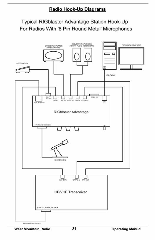
Radio Hook-Up Diagrams

32West Mountain Radio Operating Manual

33West Mountain Radio Operating Manual

RIGblaster Advantage WarrantyRIGblaster Advantage is warranted against failure due to defects in workmanship or materials for one year after the date of purchase from West Mountain Radio. Warranty does not cover damage caused by abuse, accident, misuse, improper or abnormal usage, failure to follow instructions, improper installation, alteration, lightning, or other incidence of excessive voltage or current. If failure occurs within this period, return the RIGblaster Advantage or accessory to West Mountain Radio at your shipping expense. The device or accessory will be repaired or replaced, at our option, without charge, and returned to you at our shipping expense. Repaired or replaced items are warranted for the remainder of the original warranty period. You will be charged for repair or replacement of the RIGblaster Advantage or accessory made after the expiration of the warranty period.
The Compact Disc of Radio Amateur Software Collection is excluded from any and all warranties by West Mountain Radio. Note that the programs have been provided as shareware or freeware by the software authors to the amateur radio community for their use and enjoyment. The DVD is to be used at your own risk.
West Mountain Radio shall have no liability or responsibility to customer or any other person or entity with respect to any liability, loss, or damage caused directly or indirectly by use or performance of the products or arising out of any breach of this warranty, including, but not limited to, any damages resulting from inconvenience, loss of time, data, property, revenue, or profit, or any indirect, special incidental, or consequential damages, even if West Mountain Radio has been advised of such damages.
Except as provided herein, West Mountain Radio makes no express warranties and any implied warranties, including fitness for a particular purpose, are limited in duration to the stated duration provided herein. www.westmountainradio.com 1020 Spring City Drive, Waukesha, WI 53186 tel 262-522-6503 fax 262-522-6504