RIGblaster Blue - West Mountain Radio to Digital Mode ... Mountain Radio. We think the RIGblaster...
36
www.westmountainradio.com 1020 Spring City Drive Waukesha, WI 53186 262-522-6503 [email protected] ©2014 West Mountain Radio, All rights reserved. All trademarks are the property of their respective owners. RIGblaster Blue with Bluetooth ® Wireless Technology
Transcript of RIGblaster Blue - West Mountain Radio to Digital Mode ... Mountain Radio. We think the RIGblaster...

www.westmountainradio.com1020 Spring City DriveWaukesha, WI 53186
©2014 West Mountain Radio, All rights reserved. All trademarks are the property of their respective owners.
RIGblaster Bluewith Bluetooth® Wireless Technology
2West Mountain Radio Operating Manual
Table Of Contents
Introduction Introduction to RIGblaster Blue . . . . . . . . . . . . . . . . . . . . . 3 RIGblaster Blue Features . . . . . . . . . . . . . . . . . . . . . . . . . 3 About the Supplied DVD . . . . . . . . . . . . . . . . . . . . . . . . . . 4 Introduction to Digital Mode . . . . . . . . . . . . . . . . . . . . . . . . 4Package Contents . . . . . . . . . . . . . . . . . . . . . . . . . . . . . . . . . 5Controls, Connections and Features . . . . . . . . . . . . . . . . . . 6Choosing the Correct ISC . . . . . . . . . . . . . . . . . . . . . . . . . . . 7Bluetooth® Wireless Technology Adapter Installation . . . . . . . . . . . . . . . . . . . . . . . . . . . . . . 8 Pairing RIGblaster Blue to your Windows PC with a Broadcom or Microsoft stack . . . . . . . . . . . . . . . . . . . . . . . 8 Pairing RIGblaster Blue to your Windows PC with a CSR stack . . . . . . . . . . . . . . . . . . . . . . . . . . . . . . . . . . . . . 12 UsingtheWMRDiagnosticsoftwaretoconfigurethe RIGblaster Blue . . . . . . . . . . . . . . . . . . . . . . . . . . . . . . . . . 16 Pairing a headset to the RIGblaster Blue without a Windows PC . . . . . . . . . . . . . . . . . . . . . . . . . . . . . . . . . . . 19Transceiver Connections Required Connections . . . . . . . . . . . . . . . . . . . . . . . . . . . . 20 Optional Connections . . . . . . . . . . . . . . . . . . . . . . . . . . . . 21Transceiver Settings Operating Mode . . . . . . . . . . . . . . . . . . . . . . . . . . . . . . . . . 21 Receive Settings . . . . . . . . . . . . . . . . . . . . . . . . . . . . . . . . 21 Transmit Settings . . . . . . . . . . . . . . . . . . . . . . . . . . . . . . . . 22Digital Mode Software Configuration . . . . . . . . . . . . . . . . . 23Reference RIGblaster Blue Connection Diagrams . . . . . . . . . . . . . . . 25 Icom CI-V CAT Cable Schematic . . . . . . . . . . . . . . . . . . . 28 ISC & Jumper Wiring . . . . . . . . . . . . . . . . . . . . . . . . . . . . . 28 ISCs for Some Common Radios . . . . . . . . . . . . . . . . . . . . 31 Optional Cables . . . . . . . . . . . . . . . . . . . . . . . . . . . . . . . . . 32 Digital Modes, Software & Frequencies . . . . . . . . . . . . . . 33 AT Commands . . . . . . . . . . . . . . . . . . . . . . . . . . . . . . . . . . 34
The Bluetooth® word mark and logos are registered trademarks owned by Bluetooth SIG, Inc. and any use of such marks by Bluegiga Technologies is under license. Other trademarks and trade names are those of their respective owners.

3West Mountain Radio Operating Manual
Introduction to the RIGblaster Blue
We understand you have a choice when buying Amateur Radio products and we would like to take a moment to thank you for choosing West Mountain Radio.
We think the RIGblaster Blue is a revolutionary and innovative product whichintegratestheflexibilityandconvenienceofBluetooth® with a solid and trusted platform of Amateur Radio interfaces. Whether you are interested in digital modes or hands-free phone operation, the RIG-blasterBluehasbeendesignedtogiveyouthemostflexibleapproachtoleveraging Bluetooth® technology for use in Amateur Radio. It has many outstanding features which will at the same time enhance and simplify your operating.
RIGblaster Blue Features
• Pair with a traditional PC*, smart phone or tablet for untethered digi-tal mode operating.
• Pair with a Bluetooth® headset for untethered hands-free phone.• ProvidesasounddeviceandserialporttoWindows,LinuxorMacwhichcanbeusedwithexistingAmateurRadiosoftware.
• Audio level controls (both RX & TX) on the front panel.• Pre-wiredInstantSetupConnectors–nomorecomplexjumper
wiring!• TTLrig-control(CAT/CI-V)withRS-232Cexternalization.*• VOXpush-to-talkwithadjustabledelay.• Separateaudiojacksforreceivedandtransmittedaudio.• Headsetdiscoveryandaudioleveladjustmentwithouttheuseofa
computer.• Foot-switch PTT input.• TX inhibit switch (listen-only mode).• Fully isolated transmit and receive audio. Bluetooth® connection givesextradegreeofisolation.
Pleasereadthroughthismanualfirst(especiallytheBluetooth® installa-tionsection)andyouwillfindtheRIGblasterBluewillprovideyouwithmanyyearsofreliableserviceandenjoyment.
* Rig control is only available on certain transceivers.

4West Mountain Radio Operating Manual
About The Supplied DVD
The supplied DVD is mostly a collection of various digital-mode software programs for use with sound card interfaces such as the RIGblaster Blue. The programs contained on the disc were not written by West Mountain Radio. Some are completely free while others are commercial. Wehavehowevertestedourproductsonthemajorityofthem.Amateur radio software is constantly evolving and we encourage you to visit the various authors’ websites to check for updates for software you wish to use.
We maintain a list of website addresses for the software we place onto the DVD (as best we can) and you can access this page from http://www.westmountainradio.com/links
Introduction To Digital Mode Operating
Most modern digital-modes can be operated on the RIGblaster Blue. Some of these may already be familiar to you. For instance PSK31, JT65 & RTTY are very commonly heard on the bands. If you have the abil-itytrytuningto14.070MHz(usb)andchancesareyouwillhearmultiplePSK31 QSOs taking place.
Movingupto14.073MHzyoumayhearthetonesoftheMFSKmodessuchasOlivia,Contestia,ThorandMFSK-16.Youwillalsofindthe“cricket-like”chirpingofFeldHell.Tuneto14.076MHzandyouwillhearJT65signals.Goingupanother10KHzlandsyourightinaverypopularRTTY segment.
Movingupthrough14.100MHzyoushouldhearpacketnetworks,Win-MOR and the wider band digital modes signals such as MT63, ALE and Pactor.
14.230MHz(usb)yieldsaveryactiveSSTV(SlowScanTV)frequency.ThisistraditionalanalogSSTV.Another3KHzup(14.233MHz)isthemain watering-hole of digital SSTV enthusiasts.14.236MHziscurrentlyverypopularwiththedigitalvoiceexperimentersusing FreeDV software.It is worth noting there are some modes in use which cannot be used with the RIGblaster Blue (nor any “sound-card” based interface). These are the arq modes Pactor, G-TOR, Amtor and Clover. These modes require very precise timing cycles which Windows is unable to deliver. Amtor, G-TOR and Clover are very seldom used these days but Pactor is commonly employed for mail messaging using the Winlink 2000 system.

5West Mountain Radio Operating Manual
InpracticethisisnotmuchofalimitationastheRMSExpresssoftware(using WinMOR) makes mail/e-mail messaging simple using the RIG-blaster Blue.
Many digital-modes (such as PSK31) will work far down into the noise level. It is not uncommon to see copy on your screen even when you havedifficultyhearingthesignalonyourspeaker.
This also implies you do not need to run high power levels during normal conditionsandformostdigital-modesyouwillfind20-40Wample.Infact,runningclosetomaximumoutputonyourradioisself-defeating.Inthiscase you stand a very good chance of having a spread-out badly distort-ed signal (think QRM!) and you may even damage your rig on long overs as many transceivers are not designed to run high duty-cycle transmis-sionsforextendedperiods.
Atthebackofthismanualyouwillfindasimplechartofdigital-modes,softwareandfrequenciestotry.Thesearejustsuggestionsbutwillhelpyou get started navigating the world of HF digital-modes.
Package Contents
The following is a list of the contents for the RIGblaster Blue. Verify that all the following items were included:
1 — RIGblaster Blue Unit Note: Cover is loose so you may easily remove it to installjumpers) 1 — Accessory ZipLock® bag. Contains the following: 8—Singlepinjumperwires 5 — Mini blue shunts 4 — #6 black sheet metal screws (for cover) 4 — Adhesive pads and Rubber Feet 1 — Baggie of Instant Setup Connectors 1 — Microphone cable (RJ-45 to 8 pin screw-on) 1 — 1/8 inch stereo mini plug cable 1 — RIGblaster & RIGtalk DVD 1 — 9V DC Adapter 1 — Bluetooth® Wireless Antenna 1 — Owner’s manual

6West Mountain Radio Operating Manual
PTT
in/o
ut R
CA
Con
nect
or (u
sed
with
foot
switc
h or
oth
er P
TT s
witc
h or
con
nect
ion.
Aud
io M
onito
r Jac
kB
luet
ooth
Ant
enna
Jac
k
CAT
RIG
Con
trol a
t R
S23
2 Le
vels
DC
Pow
er J
ack
(Acc
epts
7-2
0VD
C @
200
mA
cent
er
posi
tive.
Con
nect
ion
to a
RIG
run-
ner a
vaila
ble
with
SK
U#5
8257
-106
9.
2.1m
m p
lug,
cen
ter p
ositi
ve.)
Blu
etoo
th M
ode
Sw
itch:
Top:“C
onfig“-A
llowsforsoftwareconfigurationfrom
a P
C a
nd B
lue
unit
into
dis
cove
rabl
e m
ode
Mid
dle:
“PC
” - A
llow
s fo
r pai
ring
with
PC
, sm
arph
one
or ta
blet
Bot
ton:
“Hea
dset
” - A
llow
s fo
r pai
ring
with
a B
luet
ooth
he
adse
tTo
gglin
g: S
ee m
anua
l sec
tion
on “P
airin
g to
a h
eads
et
with
out a
PC
”
XM
IT L
ED
(li
ghts
whe
n P
TT
is a
ctiv
e)
Mic
roph
one
inpu
t for
8 p
in ro
und
mic
(M
ic o
utpu
t with
RJ4
5 co
nnec
tor r
adio
)
Tran
smit
audi
o le
vel:
incr
ease
/de
crea
se T
X a
udio
(driv
e)
Rec
eive
aud
io le
vel:
incr
ease
/dec
reas
e TX
au
dio
(e.g
. wat
erfa
ll br
ight
ness
, hea
dset
re
ceiv
e au
dio)
VO
X D
elay
: inc
reas
es/d
ecre
ase
PTT
rele
ase
time
Blu
etoo
th s
tatu
s LE
DS
olid
: Blu
etoo
th is
pai
red
and
conn
ecte
d w
ith c
ompu
ter,
tabl
et, s
mar
tpho
ne
o
r hea
dset
SlowBlink(1Hz):B
luetoothnotconnected
Sho
rt Fl
ash
follo
wed
by
long
del
ay (2
sec
): D
isco
verin
g an
d au
tom
atic
ally
pai
ring
with
a h
eads
et (w
hen
no P
C is
ava
ilabl
e)
TX M
ode
Sw
itch:
Top:
“VO
X” -
VO
X P
TT is
ena
bled
. A T
X s
igna
l (fro
m a
pa
ired
devi
ce) w
ill c
ause
the
radi
o to
tran
smit
Bot
tom
: “O
FF” -
Tra
nsm
it in
hibi
t (lis
ten-
only
mod
e)
CTLIN
/OUTrigcontroljack-for
conn
ectio
n to
a ra
dio
with
TTL
CAT
LIN
E IN
: con
nect
s to
RX
aud
io fr
om
trans
ceiv
er
RJ-
45 M
icro
phon
e Ja
ck
SP
KR
OU
T: C
onne
ct s
peak
er fo
r RX
aud
io m
onito
ring
(onlyifLINEIN
isconnectedtotheexternalspeakerjackoftransceiver)
Controls, Connections And Features

7West Mountain Radio Operating Manual
Choosing The Correct ISC
ConfiguringtheRIGblasterBluewithatransceiverisverysimplebyuseoftheInstantSetupConnectors(ISC).Thesetaketheplaceofjumperwiring for many common radios. They can be regarded as a “personality module” for a particular radio.
EachISCisrespectivelyidentified:IcomRoundMetal,IcomRJ45Modu-lar, Yaesu Round Metal, Yaesu Round Metal – Isolated, Yaesu RJ45 Modular, Kenwood Round Metal and Kenwood RJ45 Modular. Depend-ing on the transceiver in use, one of these ISCs will need to be installed inside the RIGblaster Blue before use. They take care of all the micro-phoneconnectionwiringthatpreviouslywasdonebyinstallingjumperwiresandshunts.Ifusinganon-standardmicrophonewiring,jumperwires and blue shunts have been provided in the package contents. The ISCs cover most popular brands and models of radios.
Observe the microphone connector on the radio. Typically it will be one of two types – either an 8-pin round metal connector or an RJ- 45 “square”modularjack.TheRIGblasterBlueisdesignedtointerfacethetransceiverthroughthemicrophonejack.BesuretoselecttheISCthatmatches the connector on the radio. Refer to the back of this manual for a chart of common radios and the correct ISC to use. Installing The ISC
Locate the correct ISC for the radio and install it on the ISC header (2 rows of 13 pins) located inside the RIGblaster Blue ensuring pin 1 on the ISC matches pin 1 on the header.
Some radios use a 4-pin round micro-phone connector, these include older Kenwood and Yaesu transceivers and some Ten-Tec radios. An adapter will be needed to use the RIGblaster Blue with these radios. The correct adapter is SKU 58136-1000 and available online for purchase.Radios with 6 pin microphone connec-tors such as the Yaesu FT-100D will require our optional “Yaesu Modular 6” cable (SKU 58118-982). This cable comeswithajumperdiagramandaresistor for correct operation.
PTT
in/o
ut R
CA
Con
nect
or (u
sed
with
foot
switc
h or
oth
er P
TT s
witc
h or
con
nect
ion.
Aud
io M
onito
r Jac
kB
luet
ooth
Ant
enna
Jac
k
CAT
RIG
Con
trol a
t R
S23
2 Le
vels
DC
Pow
er J
ack
(Acc
epts
7-2
0VD
C @
200
mA
cent
er
posi
tive.
Con
nect
ion
to a
RIG
run-
ner a
vaila
ble
with
SK
U#5
8257
-106
9.
2.1m
m p
lug,
cen
ter p
ositi
ve.)
Blu
etoo
th M
ode
Sw
itch:
Top:“C
onfig“-A
llowsforsoftwareconfigurationfrom
a P
C a
nd B
lue
unit
into
dis
cove
rabl
e m
ode
Mid
dle:
“PC
” - A
llow
s fo
r pai
ring
with
PC
, sm
arph
one
or ta
blet
Bot
ton:
“Hea
dset
” - A
llow
s fo
r pai
ring
with
a B
luet
ooth
he
adse
tTo
gglin
g: S
ee m
anua
l sec
tion
on “P
airin
g to
a h
eads
et
with
out a
PC
”
XM
IT L
ED
(li
ghts
whe
n P
TT
is a
ctiv
e)
Mic
roph
one
inpu
t for
8 p
in ro
und
mic
(M
ic o
utpu
t with
RJ4
5 co
nnec
tor r
adio
)
Tran
smit
audi
o le
vel:
incr
ease
/de
crea
se T
X a
udio
(driv
e)
Rec
eive
aud
io le
vel:
incr
ease
/dec
reas
e TX
au
dio
(e.g
. wat
erfa
ll br
ight
ness
, hea
dset
re
ceiv
e au
dio)
VO
X D
elay
: inc
reas
es/d
ecre
ase
PTT
rele
ase
time
Blu
etoo
th s
tatu
s LE
DS
olid
: Blu
etoo
th is
pai
red
and
conn
ecte
d w
ith c
ompu
ter,
tabl
et, s
mar
tpho
ne
o
r hea
dset
SlowBlink(1Hz):B
luetoothnotconnected
Sho
rt Fl
ash
follo
wed
by
long
del
ay (2
sec
): D
isco
verin
g an
d au
tom
atic
ally
pai
ring
with
a h
eads
et (w
hen
no P
C is
ava
ilabl
e)
TX M
ode
Sw
itch:
Top:
“VO
X” -
VO
X P
TT is
ena
bled
. A T
X s
igna
l (fro
m a
pa
ired
devi
ce) w
ill c
ause
the
radi
o to
tran
smit
Bot
tom
: “O
FF” -
Tra
nsm
it in
hibi
t (lis
ten-
only
mod
e)
CTLIN
/OUTrigcontroljack-for
conn
ectio
n to
a ra
dio
with
TTL
CAT
LIN
E IN
: con
nect
s to
RX
aud
io fr
om
trans
ceiv
er
RJ-
45 M
icro
phon
e Ja
ck
SP
KR
OU
T: C
onne
ct s
peak
er fo
r RX
aud
io m
onito
ring
(onlyifLINEIN
isconnectedtotheexternalspeakerjackoftransceiver)
Figure shows installation of a Kenwood RJ45 Modular ISC inside the RIGblaster Blue. Notice the orientation of the ISC and the location of pin 1.

8West Mountain Radio Operating Manual
Bluetooth® Wireless Technology
If you are planning on using the RIGblaster Blue on a Windows PC, then you will require a USB Bluetooth® Adapter if your computer does not already have one. Suitable adapters (SKU #58140-1505) are available from West Mountain Radio.
Follow the Bluetooth® Adapter installation instructions. Note there are no specificRIGblasterBluedriversrequired.Werecommendyoufullyinstallthe Bluetooth® Protocol Stack (The CD software) that accompanies your Bluetooth® Adapter.
Your installation may differ slightly from what’s documented below due to different versions of Windows or different versions of Bluetooth® stack. FordefinitivedirectionsrefertothemanualthatcamewithyourPCorBluetooth® adapter.
Pairing RIGblaster Blue to your Windows PC with a Broadcom or Microsoft stack
The Microsoft and Broadcom stack work and operate very similar. The differences between them will be detailed during the documentation of the pairing process.
1. Makesurethe‘BLUE’switchontheRIGblasterBlueisinthe‘Config’position. The RIGblaster Blue will not be discoverable if it is not in this position.
2. On the PC, open the Bluetooth® Devices window. You should be able to get this by double clicking on the Bluetooth® icon in the system tray on the bottom right of Windows (near the clock). If you do not have a Bluetooth® icon in your status bar, you can open Bluetooth® Devices from the Windows Control panel. To get to the Windows Control panel, press the Start button and select ‘Control Panel’ from the start menu. On Windows 8, best way to get the control panel is to type “con-trol panel” from the main tile Start screen.

9West Mountain Radio Operating Manual
3. On the PC’s Bluetooth® Devices window, press the ‘Add Device’ but-ton.
4. The PC will search for and discoverable Bluetooth® devices. Eventu-allyitshouldfindtheRIGblaster.Highlight/selecttheRIGblasterandpressthe‘Next’button.
5. Windowsshoulddisplayasuccessmessage,press‘Close’toexitthis message.

10West Mountain Radio Operating Manual
6. The RIGblaster Blue should now be shown in the Bluetooth® Devices window.
7. Double click on the RIGblaster icon in the Bluetooth® Devices win-dow. If it opens a RIGblaster Device control window, then you have the Broadcom stack installed.
When using this stack, sometimes you have to go to this Window and press the ‘Connect’ button to connect either the headset (audio)orserialport(COMx)functionality.TheMicrosoftstackdoes this automatically.

11West Mountain Radio Operating Manual
8. Theserialport(COMx)functionalitydoesnotalwaysgetenabledwhen you pair with the device. Toenableitorconfigureit,selectthe‘Settings’or‘Config’menuoption when you click on the Bluetooth® icon on the Windows system tray. If you do not have the Bluetooth® icon on the system tray, it can be found in the Bluetooth® Devices window (usually as a right-click option or as a menu option on the right). The Bluetooth® settings window will often have several settings that can be made or changed,theserialport(COMx)functionalityisonitsowntab:

12West Mountain Radio Operating Manual
9. TheCOMxportusedforRIGblasterBlueconfigurationorRIGcontrol(using the RIGblaster’s DB9 or CIV port) is the COM port in the ‘Out-going’ direction. If you do not have an outgoing COM port, press the ‘Add’ button to make one:
From this dialog window, you want to create an Outgoing port, and make sure the device selected is the RIGblaster.
Pairing RIGblaster Blue to your Windows PC with a CSR stack
1. Makesurethe‘BLUE’switchontheRIGblasterBlueisinthe‘Config’position. The RIGblaster Blue will not be discoverable if it’s not in this position.
2. On the PC, open the My Bluetooth® Devices window. You should be able to get this by double clicking on the Bluetooth® icon in the system tray on the bottom right of Windows (near the clock). If you do not have a Bluetooth icon in your status bar, you can open Bluetooth® Devices from the Windows Control panel. To get to the Windows Control panel, press the Start button and select ‘Control Panel’ from the start menu. On Windows 8, best way to get the con-trol panel is to type “control panel” from the main tile Start screen.
3. In the My Bluetooth® Devices, press the ‘Add Device’ button and select ‘All’ or ‘Audio/Video Device’.

13West Mountain Radio Operating Manual
4. The PC will search for and discoverable Bluetooth® devices. Eventu-allyitshouldfindtheRIGblaster.Highlight/selecttheRIGblasterandpressthe‘Next’button.
5. Windowsshoulddisplayasuccessmessage,press‘Finish’toexitthis message.

14West Mountain Radio Operating Manual
6. The RIGblaster Blue should now be shown in the Bluetooth® Devices window.
7. Double click on the ‘RIGblaster’ in the My Bluetooth® Devices win-dow to open the control panel for this device:
15West Mountain Radio Operating Manual
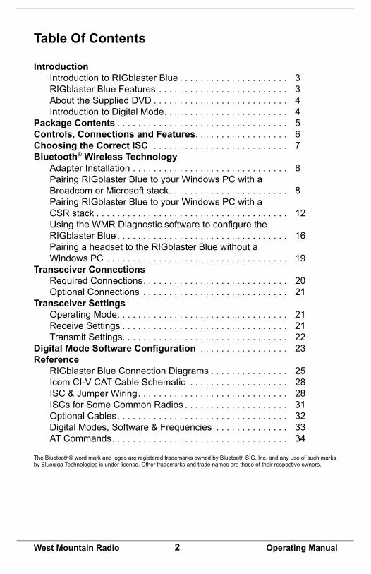
Usually Windows will automatically reconnect to the audio (headset profile)andserialCOMxport(serialportprofile)–butifthisdoesn’thappen then double-click on those items and Windows will connect them and make them available to the system.
8. TofindtheCOMxportassignedtotheRIGblasterBlue,opentheBluetooth® Settings window. This can be opened by pressing the ‘Bluetooth® Settings’ button on the My Bluetooth® Devices window. On XP this button is not there, but can be found in the Windows Con-trolPanel(seeStep2(above)fordirectionsonfindingtheWindowsControl Panel).
TheCOMxportusedforRIGblasterBlueconfigurationorRIGcontrol(using the RIGblaster’s DB9 or CIV port) is the COM port in the ‘Out-going’ direction. If you do not have an outgoing COM port, go back to the control panel for the Bluetooth® device (see previous step) and doubleclickonthe‘SerialPortProfile’tocreatetheCOMxport.

16West Mountain Radio Operating Manual
Using the WMR Diagnostic software to configure the RIGblaster Blue
The WMR Diagnostic software provided by West Mountain Radio can be usedtoconfigureseveralparametersoftheRIGblasterBlue.Formostpeoplemanyofthoseconfigurationsdon’tneedtobechanged.Thissoftware can be used to pair the RIGblaster Blue with a Bluetooth® head-setforvoicemodes.IfyoudonothaveWindows(usingaMac,Linuxortablet), the Bluetooth®SPPCOMportcanbeusedin‘config’modetoacceptATcommandstoconfigurethedeviceinstead.Thisiswhatthemain screen of the WMR diagnostic software looks like:
To launch the Bluetooth®configurationportionoftheWMRDiagnosticsoftware,rightclickontheCOMxportassignedtotheoutgoingSPPportoftheRIGblasterBlueandselect‘ConfigureRIGblasterBlue’.Tofindtheoutgoing port, refer to the pairing directions in the previous section.

17West Mountain Radio Operating Manual
CloseCOMx Close the COM port. When closed the COM port will be available to other applications.
Read configuration WillreadtheRIGblasterBlue’scurrentconfigurationandrefreshthewindow.
Friendly Name IntheeventyouownmorethanoneRIGblasterBlue,thisfieldcanbeused to alter the name of the device to differentiate between them. If you change this value, you may have to remove the pairing and re-pair with the RIGblaster Blue for the new value to take effect on your system.
Baud Rate, Parity, Stop Bits ThisconfigurestheserialsettingsoftheSerialRS232DB9portandtheTTL CTL IN/OUT port. You should change these values to match the se-rial settings of the radio rig you are attempting to control via CAT. (Setting avalueof‘2’forstopbitswillworkwithdevicesthatexpect1stopbits,so if you’re not sure then leave this value at ‘2’).
Headset and PC/Tablet Gain ThiscontrolstheaudioamplifiergainsinsidetheRIGblasterBlue.Formostpeoplethedefaultvalueswillsuffice,butthiswasprovidedintheeventyourradiorigwasexceptionallyquitorexceptionallyloud.

18West Mountain Radio Operating Manual
The ‘Headset Gain’ section controls the gains when the BLUE switch is in ‘headset’ mode.
The ‘PC/Tablet’ section controls the gains when the BLUE switch is in ‘PC’ mode.
‘From Rig’ controls the receive audio levels coming from the transceiver.
‘To Rig’ controls the transmit audio levels going to the transceiver.
The ‘Headset Gain’ ‘To Rig’ volume is one value that may need user attention. Most Bluetooth®headsetsprovidenomethodofadjustingthegain of its microphone, so people who talk quietly or have a Bluetooth® headset with a weak microphone may need to raise this gain.
Itmaytakesomeexperimentationtodeterminethecorrectvaluesospoken audio triggers the VOX in the RIGblaster Blue without causing clipping or distorting because the gain is too high.
Thereisalsoawayofadjustingthisgainwithoutusingthediagnosticsoftware, see the section labeled ‘Pairing a headset to the RIGblaster Blue without a Windows PC’ in this manual for directions.
Write Configuration This button will write the values discussed above back to the RIGblaster blue.
Factory Reset This button will return the RIGblaster Blue back to factory default set-tings.
Device Inquiry Scan When pressed, the RIGblaster Blue will search for a compatible Blue-tooth® headset for pairing. First, initiate the pairing process of your Blue-tooth® headset (refer to the manual of your Bluetooth® headset). Second, press this button. After about 20s the RIGblaster Blue will stop looking for discoverable devices, and will display the devices found in the ‘Device’ pull-down below.
Device After pressing the ‘Device Inquiry Scan’ button, this pull-down will display all the valid Bluetooth® headsets that were found. Use this pull-down to select the Bluetooth® headset you want to use and press the ‘Pair Head-set’button.Afterpressingthe‘ReadConfiguration’button,thiswillshow

19West Mountain Radio Operating Manual
the Bluetooth® headset that the RIGblaster Blue is currently paired to.
Pair Headset Pressing this button will cause the RIGblaster Blue to pair with Blue-tooth® headset selected in the ‘Device’ pull-down. See the ‘Device Inquiry Scan’ and ‘Device’ sections above for more info.
Pairing a Headset to the RIGblaster Blue without a Win-dows PC
1. Initiate the pairing process of the desired Bluetooth® headset. Refer to the manual of your Bluetooth® headset, but it’s usually done by pressing and holding down the main button for a set period of time.
2. Toggle the ‘BLUE’ switch on the front panel between ‘PC’ and ‘Head-set’ at least 6 times, and end on ‘Headset’
3. After a few seconds the ‘Status’ LED of the RIGblaster blue should start a blinking pattern of short green followed by long delay of unlit (2seconds).ThissignifiesthattheRIGblasterBlueissearchingfordiscoverable devices.
4. Afterabout20seconds,theRIGblasterBlueshouldfindyourhead-set and pair with it. After it pairs, the RIGblaster Blue will now run in normal ‘headset’ mode and attempt to connect to the headset as normal. Your Bluetooth® headset might make a special tone or signal when there is a successful pair or connection.
5. When the RIGblaster Blue is operating in normal ‘headset’ mode, the ‘Status’ LED will have a slow blink when not connected to the headset and a solid lit LED when connected to the headset. When using this mode to have the RIGblaster Blue pair with a Bluetooth® headset,itwillpairwiththefirstcompatibledevicethatitsees.Ifyouare in an area with several Bluetooth® devices it is possible that it will pair with one of those devices. Therefore if you use this mode to pair with your headset and it appears to not be pairing correctly, try turn-ing off other Bluetooth® devices in your area or try moving to an area that has no Bluetooth® devices.
Once a Bluetooth® headset has been paired, going to ‘headset’ mode will always connect to this headset.
Adjusting Headset Microphone Gain
1. If you are paired to a Bluetooth® headset, but the VOX in the RIG-blaster Blue is not triggering when you speak, you may need to adjustthemicrophonegainintheRIGblasterBlue.Thiscanbedone‘live’, while connected to the Bluetooth® headset, to test the micro-phone gain while speaking:
20West Mountain Radio Operating Manual
2. Toggle the ‘BLUE’ switch on the front panel between ‘PC’ and ‘Head-set’ at least 6 times, and end on ‘’PC’.
3. The RIGblaster Blue will reconnect with the headset, and the Status LED on the RIGblaster Blue will start blinking fast to signify the mode is ready.
4. Togglingthe‘BLUE’switchfrom‘PC’to‘config’willraisethemicro-phone gain one level.
5. Toggling the ‘BLUE’ switch from ‘PC’ to ‘headset’ will lower the micro-phone gain one level.
6. Repeats steps 3 and 4 until the desired level is reached. Generally, you want to raise the level until you the point where speaking com-fortably triggers the VOX in the RIGblaster Blue. You can tell this happens because the XMIT LED on the RIGblaster Blue will light (makesurethe‘TX’switchisin‘vox’mode).
7. Apower-cycleisrequiredtoexitthismode.
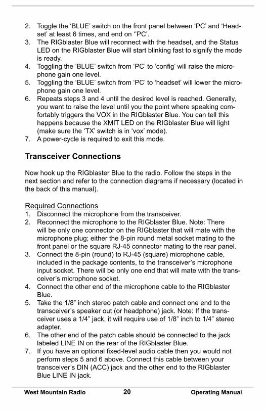
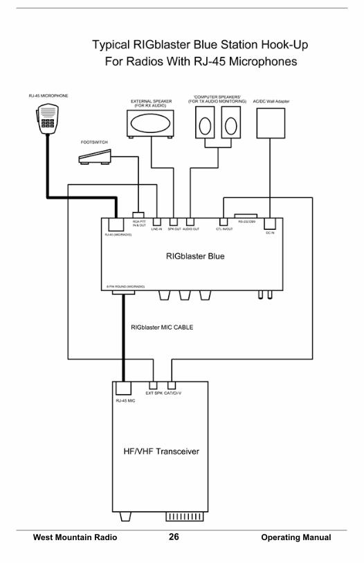
Transceiver Connections
Now hook up the RIGblaster Blue to the radio. Follow the steps in the nextsectionandrefertotheconnectiondiagramsifnecessary(locatedinthe back of this manual).
Required Connections1. Disconnect the microphone from the transceiver.2. Reconnect the microphone to the RIGblaster Blue. Note: There
will be only one connector on the RIGblaster that will mate with the microphone plug; either the 8-pin round metal socket mating to the front panel or the square RJ-45 connector mating to the rear panel.
3. Connect the 8-pin (round) to RJ-45 (square) microphone cable, included in the package contents, to the transceiver’s microphone input socket. There will be only one end that will mate with the trans-ceiver’s microphone socket.
4. Connect the other end of the microphone cable to the RIGblaster Blue.
5. Take the 1/8” inch stereo patch cable and connect one end to the transceiver’sspeakerout(orheadphone)jack.Note:Ifthetrans-ceiverusesa1/4”jack,itwillrequireuseof1/8”inchto1/4”stereoadapter.
6. Theotherendofthepatchcableshouldbeconnectedtothejacklabeled LINE IN on the rear of the RIGblaster Blue.
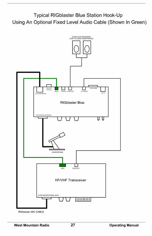
7. Ifyouhaveanoptionalfixed-levelaudiocablethenyouwouldnotperform steps 5 and 6 above. Connect this cable between your transceiver’sDIN(ACC)jackandtheotherendtotheRIGblasterBlueLINEINjack.
21West Mountain Radio Operating Manual
Optional ConnectionsAdditionaljacksareprovidedontherearoftheRIGblasterBlueforop-eration enhancement:1. Serial DB-9. This connector can be used to interface transceivers
that require RS-232C level CAT. 2. CTLIN/OUT.ThisisaTTLleveljackprovidingCI-V/CATrigcontrol.
Manyradioscanbeinterfacedtothisjackwithalow-costcableforcomplete rig control with suitable software.
3. AUDIOOUT.Thisjackprovidesatransmittedaudiooutput.Connectamplifiedcomputerspeakersorapairofminiearphonesherefortransmit monitoring.
4. SPKROUT.Thisjackprovidesarigreceiveaudiooutput.Connectalowimpedanceexternalspeakerhereonlyifnotusinganoptionalfixed-levelaudiocable.
5. PTTIN/OUT.ThisRCAphonojackisprimarilyusedforconnectiontoa foot-switch for PTT. The contacts are in parallel with the RIGblaster BluePTTrelay(rated30VDC2Amax.)andthetransceiver’smicro-phonePTTline.Itwillfloatatthesamevoltage.
Transceiver Settings
Operating ModeMostdigitalmodeprogramsexpectthetransceivertobeusedinusb(up-per sideband).
Traditionally, digital mode transmission was done in lsb (lower sideband) most modern software makes the assumption this is no longer the case. For some modes such as PSK31 (which is sideband independent) it actually makes no difference but to be “on the same page” with other operators you should choose usb unless you have good reason not to.
BecausetheRIGblasterBlueconnectstoatransceivermicrophonejackit is important not to choose a “data” or “dig” mode on the radio. These modestypicallyexpecttransmitmodulationthroughanaccessoryjackandwilldisablethemicrophonejack.
Receive SettingsFor most digital modes setting your AGC (automatic gain control) to “auto”or“fast”isrecommended.Youmayfindsomemodes(e.g.,FeldHell,CW&SSB)willbenefitfromslowAGCaction.Thereisnohardandfastruleforthissoexperimentationisadvised.
Receivefilteringisnormallyleft“wideopen”butifyouhavetheabilityto

22West Mountain Radio Operating Manual
alter your receive bandwidth in usb mode you may do so which may help with co-channel interference in crowded conditions.
If your radio has DSP noise reduction it should be turned off. The only modeswhichmaybenefitfromsomenoisereductionareFeldHell,CW&SSB.UsingDSPnoisereduction(orDSPauto-notchfiltering)willad-versely affect reception of many digital signals.
The transceiver’s Noise Blanker ideally should be turned off but that may not be possible if you live in a high noise area.
Transmit SettingsThe most important thing to avoid when transmitting digital modes is a distortedsignal.Thiscanhappenwhenthedrivetothemicrophonejackis too high or when your transceiver’s ALC (automatic level control) is ac-tive.ItisrecommendedtoleaveyourRFPowercontrolsettomaximum(usually100W)andadjustthedrivelevelusingtheRIGblaster’sXMITLEVELcontroland/ortheWindowsplaybackslidertoachieveyourfinaloutputpower.Note:It’simportanttorealizethatsettingyourRFPowercontrol to 100W does not imply you are transmitting a 100W signal! It simply leaves enough “headroom” to prevent ALC action from occurring.
Determining your output power can be problematic with digital mode operating as some modes have a high P(peak) to P(mean) ratio. Unless your power meter shows PEP with hold you may not get a very accurate indication of output power in these modes. Fortunately PSK31 has a P(peak)toP(mean)ratioofapproximately0.79sowhatyouseeonthemeter is close to your actual output power.
On the other hand, MT63 has a ratio of about 0.1 which would mean that transmittingaproperlyadjustedMT63signalmayindicateonly10Wonan average power meter for a peak output of 100W. Trying to increase the drive will only distort the signal!
There is never a good reason to use your speech processor function while transmitting a digital mode – so turn it off!
As you will be transmitting in usb mode, the transceiver’s mic gain control will have a bearing on your output power. We recommend you leave your micgainsettoyournormallevelforoperatingphoneandonlyadjustdrive with the XMIT LEVEL and/or Windows playback slider control.
PSK31 rule-of-thumb: Ensure no ALC indication is shown on your meter while transmitting and aim for no more than 40W output. You should be transmitting a clean signal and being a “good HF neighbor”.
23West Mountain Radio Operating Manual
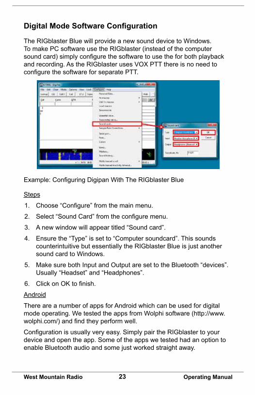
Digital Mode Software Configuration
The RIGblaster Blue will provide a new sound device to Windows. To make PC software use the RIGblaster (instead of the computer soundcard)simplyconfigurethesoftwaretousetheforbothplaybackand recording. As the RIGblaster uses VOX PTT there is no need to configurethesoftwareforseparatePTT.
Example:ConfiguringDigipanWithTheRIGblasterBlue
Steps
1. Choose“Configure”fromthemainmenu.
2. Select“SoundCard”fromtheconfiguremenu.
3. A new window will appear titled “Sound card”.
4. Ensure the “Type” is set to “Computer soundcard”. This sounds counterintuitivebutessentiallytheRIGblasterBlueisjustanothersound card to Windows.
5. Make sure both Input and Output are set to the Bluetooth “devices”. Usually “Headset” and “Headphones”.
6. ClickonOKtofinish.
Android
There are a number of apps for Android which can be used for digital mode operating. We tested the apps from Wolphi software (http://www.wolphi.com/)andfindtheyperformwell.
Configurationisusuallyveryeasy.SimplypairtheRIGblastertoyourdevice and open the app. Some of the apps we tested had an option to enableBluetoothaudioandsomejustworkedstraightaway.

24West Mountain Radio Operating Manual
DroidPSK
DroidSSTV

25West Mountain Radio Operating Manual
26West Mountain Radio Operating Manual
27West Mountain Radio Operating Manual

28West Mountain Radio Operating Manual
Icom CI-V CAT Cable SchematicIcom uses the same CI-V interface for nearly all their transceivers. This optional cable (SKU 58107-971) is available from West Mountain Radio formodestcostbutwerealizeyoumaywanttosaveafewdollarsandmake it yourself. Shown below is how the cable should be wired.
Note: A stereo 1/8” patch cable with a stereo-to-mono adapter will not work!

29West Mountain Radio Operating Manual
ISC & Jumper WiringKenwood, Alinco, Elecraft & SGC with8pinround-metalmicjack
ISC labeled: Kenwood 8 Pin Round Metal
ICOM with8pinround-metalmicjack
ISC labeled: Icom 8 Pin Round Metal
Older Yaesu Radios with8pinround-metalmicjack(ThisjumperingisforolderYaesuradioswithmicrophones that have common PTT & audio ground and older hand mics, desk mics, desk mics and Heil mics)
ISC labeled: Yaesu 8 Pin Round Metal

30West Mountain Radio Operating Manual
Newer Yaesu Radios with8pinround-metalmicjackUse this for FT-950, FT-2000, FTDX-3K,5K,9K(ThisISCalsousedforFlex6000series, Ten Tec Omni VII & Orion II)
ISC labeled: Yaesue 8 Pin Round - Isolated
ICOM & Alinco Radios withRJ-45modularmicjack
ISC labeled: Icom RJ-45 Modular
Kenwood withRJ-45micjack
(Use for most, but not all Kenwood FM rigs)
ISC labeled: Kenwood RJ-45 Modular

31West Mountain Radio Operating Manual
ISCs for Some Common Radios
Manuf. Model ISCIcom All8pinroundmicjackradios(e.g.,IC-
746, IC756/Pro/III, IC-7600)Icom 8-pin Round
Icom AllRJ-45modularmicjackradios(e.g.,IC-703, IC-706, IC-7000)
Icom RJ-45 Modular
Yaesu Allolder8pinroundmicjackradios(e.g., FT-840, FT-757)
Yaesu 8 Pin Round
Yaesu Allnewer8pinroundmicjackradios(e.g., FT-847, FT-950, FT-1000, FTDX-1200, FTDX-3000, FTDX-5000, FTDX-9000)
Yaesu 8 Pin Round - Isolated
Yaesu AllRJ-45modularmicjackradios(e.g.,FT-817, FT-857, FT-897, FT-450
Yaesu RJ-45 Modular
Kenwood All8pinroundmicjackradios(e.g.,TS-570, TS-2000, TS-590S, TS-990S)
Kenwood 8 Pin Round
Kenwood mostRJ-45modularmicjackradios(e.g., TM-V71)
Kenwood RJ-45 Modular
Elecraft K3&K2usethesamemicjackasKenwood
Kenwood 8 Pin Round
Ten Tec Omni VII & Orion II use the same mic jackasnewerYaesuradios
Yaesu 8 Pin Round - Isolated
Flex Flext1500and3000usethesamemicjackasYaesuRJ-45radios
Yaesu RJ-45 Modular
Flex Flex5000and6000seriesusethesamemicjackasnewerYaesuradios
Yaesu 8 Pin Round - Isolated
Yaesu withRJ-45modularmicjackUse this for FT-817, FT-857, FT-897 & FT-450
ISC labeled: Yaesu RJ-45 Modular
32West Mountain Radio Operating Manual
Optional CablesCATThe RIGblaster Blue is equipped with TTL and RS-232C level CAT. This makes it possible to use software for logging or radio control in addition to digital modes all through the same interface.
MostmodernradioshaveaCATjackandwithveryfewexceptionstheRIGblaster Blue can be connected to this via an optional cable for full computercontrol.TheCATjackonyourradioisaserialinterface(usingTxD/RxD)whichcanreceiveinstructionsandsendinformationbacktoyour computer to be used with suitable software.
TheserialinterfaceontheRIGblasterBlueisexternalizedontheRIGCTLjack(TTL)ortheDB-9(RS-232C).Note:Bothjackscannotbeinuse at the same time.
CAT Cables Available From West Mountain Radio:Cable SKU# Used On58107-971 All CI-V equipped Icom radios (e.g. Icom with a
“remote”jack)58108-972 Yaesuradioswithan8-pinminiDINCATjack(e.g.
FT-817, FT-857, FT-897)58108-974 Yaesuradioswitha6-pinDINCATjack(e.g.FT-736,
FT-747, FT767, FT-990)58119-1432 KenwoodradioswithanRS-232CCATjack(e.g.TS-
480, TS-570, TS-2000)
FLA–FixedLevelAudioReceiveaudiocanoftenbeobtainedfromanaccessory(DIN)jackon a transceiver. You may prefer to use this audio source instead of connectingtotheexternalspeakerjackwhichmutestheinternalspeakerin the transceiver. If you have one of these cables, you use it in place of the stereo patch cable provided with the RIGblaster.
FLA Cables Available From West Mountain Radio
Cable SKU# Used On58129-993 ICOM Radio ACC1 to Soundcard Cable. Fits any
Icomwithan8-pinACC1jack58131-996 FixedLevelAudioCable.RCAtoStereomini-plug.
Used on some Yaesu radios58131-997 Data Port to Soundcard Cable. For radios with a 6-pin
miniDINDatajack

33West Mountain Radio Operating Manual
Digital-Modes, Software And Frequencies
A complete list of digital-modes, software and HF frequencies would be difficulttofind,however,belowisaabrief(non-exhaustive)compilationof suggested frequencies to help get oriented with the RIGblaster Advantage.MostfrequenciesgivenherereflectcurrentNorthAmericanpractices. Many of these are shared internationally, but if in doubt, check withanationalamateurradioorganizationforrecommendations.
There are many Internet resources that provide further information on operating digital-Modes and a good place to start is K3UK’s Digital Radio Yahoo!® forum: http://groups.yahoo.com/group/digitalradio/
Digital Mode
Software Frequencies Notes
PSK31 FLdigi,AirlinkExpress,DM780,Digipan,MixW,MultiPSK, TruTTY, WinWarbler et al.
3.580MHz(usb)7.035MHz(usb)10.140MHz(usb)14.070MHz(usb)18.100MHz(usb)21.070MHz(usb)24.920MHz(usb)28.120MHz(usb)
Analog SSTV
MMSSTV,MultiPSK,MixW 7.171Mhz(lsb)14.230Mhz(usb)
Digital SSTV
EasyPal 3.713MHz(lsb)7.173MHz(lsb)14.233MHz(usb)
RTTY MMTTY, TruTTY,DM780, FLdigi, MultiPSK et al
14.080-14.090MHz Traditional operating was in lsb but many today use usb
JT-65 WSJT, JT65-HF, MultiPSK 1.838MHz(usb)3.576MHz(usb)7.039MHz(usb)7.076MHz(usb)14.076MHz(usb)21.076MHz(usb)28.076MHz(usb)
Hellsch-reiber
FLdigi,MultiPSK,MixW,DM780
14.063MHz(usb)
Olivia FLdigi,MixW,MultiPSK,DM780
14.074MHz(usb)14.1065MHz(usb)
Digital Voice
Free DV 14.236MHz(usb)
HF Packet Radio
Sound Modem, AGWPE, MultiPSK,MixW
14.1018MHz(usb) Tones will be at 1400/1600Hzonthe waterfall
34West Mountain Radio Operating Manual
Digital Mode
Software Frequencies Notes
VHF APRS Sound Modem, AGWPE, MultiPSK,MixW
144.390Mhz(fm) International APRS frequencies vary.
AT Commands
In the event that you do not have a Windows PC and you need to changesomeoftheconfigurationvaluesoftheRIGblasterBlue,theseAT commands are available. Sending these AT commands requires a terminal software program that can open the Bluetooth SPP port. The 'BLUE' switch on the RIGblaster Blue front panel needs to be in the 'config'position.
All commands should end in a new-line (carriage-return or line-feed). Allcommands(withtheexceptionofAT,ATE0,andATE1)canbeusedin write or read mode. A write mode contains a '=' followed by a value – this will write the new value to the RIGblaster Blue. A read mode instead contains a '?' at the end, at which point the RIGblaster Blue will display the current value.
Writeexample:AT*DVICE=00:00:00:00:00:00
Readexample:AT*DVICE?
AT Command Summary
Command DescriptionAT This command does nothing. RIGblaster Blue will
respond with “OK”ATE0ATE1
Will enable (ATE1) or disable (ATE0) local-echo. If local-echo is enabled, the RIGblaster Blue will echo characters typed or entered in the terminal software
AT*LABEL=xxxx Sets the friendly name of the RIGblaster BlueAT*MGANH=xAT*MGANP=xAT*AGANH=xAT*AGANP=x
Xisavaluefrom0to22andsetsthisamplifiergain.MGANH is “headset” from rigMGANP is “pc/tablet” from rigAGANH is “headset” to rigAGANP is “pc/tablet” to rig

35West Mountain Radio Operating Manual
AT*BAUDR=x Set the baud rate used on the Serial RS232 and CTL IN/OUT port when in “pc” mode.
AT*PARITY=x Set the parity mode used on the Serial RS232 and CTL IN/OUT port when in “pc” mode. 0=none, 1=odd, 2=even
AT*SBITS=x Set the number of stop bits used on the Serial RS232 and CTL IN/OUT port when in “pc” mode. Validvaluesforxare1and2
AT*INQRY This will initiate a search for discoverable devices. This will be used when searching for a Bluetooth headset to pair to the RIGblaster Blue. This takes about 20 seconds. When done, it will display all found devices and their MAC address, followed by AT*INQCT
AT*DVICE=xx:x xx:xx:xx
This will pair the RIGblaster Blue to the Bluetooth headsetwiththespecifiedMACaddress.Tofindvalid MAC addresses, use the AT*INQRY command documented above.

RIGblaster Blue WarrantyRIGblaster Blue is warranted against failure due to defects in workmanship or materials for one year after the date of purchase from West Mountain Radio. Warranty does not cover damage caused by abuse, accident, misuse, improper or abnormal usage, failure to follow instructions, improper installation, alteration,lightning,orotherincidenceofexcessivevoltageorcurrent.Iffailureoccurs within this period, return the RIGblaster Blue or accessory to West MountainRadioat yourshippingexpense.Thedeviceoraccessorywill berepaired or replaced, at our option, without charge, and returned to you at our shippingexpense.Repairedorreplaceditemsarewarrantedfortheremainderof the original warranty period. You will be charged for repair or replacement of the RIGblaster Blueoraccessorymadeaftertheexpirationofthewarrantyperiod.
The Compact Disc ofRadioAmateurSoftwareCollectionisexcludedfromanyand all warranties by West Mountain Radio. Note that the programs have been provided as shareware or freeware by the software authors to the amateur radiocommunityfortheiruseandenjoyment.TheDVDistobeusedatyourown risk.
West Mountain Radio shall have no liability or responsibility to customer or any other person or entity with respect to any liability, loss, or damage caused directly or indirectly by use or performance of the products or arising out of any breach of this warranty, including, but not limited to, any damages resulting from inconvenience, loss of time, data, property, revenue, or profit, or any indirect, special incidental, or consequential damages, even if West Mountain Radio has been advised of such damages.
Exceptasprovidedherein,WestMountainRadiomakesnoexpresswarrantiesand any implied warranties, including fitness for a particular purpose, are limited in duration to the stated duration provided herein. www.westmountainradio.com 1020 Spring City Drive, Waukesha, WI 53186 tel 262-522-6503 fax 262-522-6504


![QUEENSLAND MEDICAL WOMEN’S SOCIET Y ]NC. QMWS …€¦ · The “mobilisation” had been incredibly effective - nurses visiting mountain villages, radio announcements, church announcements](https://static.fdocuments.in/doc/165x107/5eb1d1f9cd5bd14e751fa1ae/queensland-medical-womenas-societ-y-nc-qmws-the-aoemobilisationa-had-been.jpg)