RI 600 ENGINE MANUAL - RotorWay
74
RI 600 ENGINE MANUAL OPERATION AND MAINTANCE OF RI600N (NORMALLY ASPIRATED) AND RI600S (SUPERCHARGED) HELICOPTER ENGINES MAY 2009, REV – 1.0
Transcript of RI 600 ENGINE MANUAL - RotorWay
RI 600 ENGINE MANUAL
OPERATION AND MAINTANCE OF
RI600N (NORMALLY ASPIRATED)
AND
RI600S (SUPERCHARGED)
HELICOPTER ENGINES
MAY 2009, REV – 1.0

RotorWay International INTRODUCTION RI600 Engine Manual Page 2
Revision Date Description Approved By:
1.0 May-19-2009 Initial rewrite documenting Talon updates RMc
RotorWay International INTRODUCTION RI600 Engine Manual Page 3
WARNING
The construction and operation of “Home-Built Aircraft” of this type is demanding and could inflict serious injury and possible death. No such operation, construction or undertaking should be initiated unless thorough and complete knowledge, preparation and instruction are available and utilized. The seller (and its agents, servants, employees, contractors, successors, and assigns) makes no warranties express or implied regarding the clarity or correctness of the plans, ease of construction or operation nor the safety of this aircraft or any part thereof. Furthermore, buyer (and his heirs, administrators and assigns) releases and holds said seller (and its agents, servants, employees, contractors, successors, and assigns) harmless from any and all liability, damages, and causes of action which may be incurred by buyer or any third party as a result of the purchase, use, construction and/or operation of said aircraft (or any part thereof) or plans for same. Buyer assumes all risk and responsibility relative to the construction and/or operation of said aircraft. Seller admits no liability by publication of this warning.
RotorWay International INTRODUCTION RI600 Engine Manual Page 4
Introduction
The RI 600 powerplant from RotorWay International has been completely assembled and dynamometer tested by factory technicians. Precise parts tolerances, assembly techniques and performance parameters are required of every engine leaving the factory. The oil pressure and ignition timing was adjusted to specification and fuel flow verified to be in the proper range at various power levels. The engine has been run long enough for the initial seating of the piston rings to occur. While the extended initial run-in period on your engine is very important, this critical period of “break in” was conducted in a tightly controlled and monitored condition in a dynamometer. As a result, every engine leaving the factory meets a tight parameter of torque and horsepower requirements. After the engine has successfully completed its dynamometer run, a variety of additional adjustments and checks are performed prior to crating and shipment. This includes a valve lash adjustment and a re-torque of all bolts to specification. All open passages are plugged to help prevent moisture and dirt contamination. It is very important to store the engine in a clean and dry environment prior to installation in the helicopter. From this point on, the responsibility for longevity and reliability of the engine is yours. Before you remove the lid from your engine crate, it is important to read and familiarize yourself with this entire manual. We have attempted to address even the most basic procedures involving the proper maintenance and operation of the power plant. It is essential that proper and timely maintenance be performed. If you have any questions or if there is anything you are not sure about, please give our customer service department a call. We advise you to attend our training program prior to starting the engine. The hands on instruction regarding the proper care and operation of the engine is extremely valuable to even the best mechanic. A recommended maintenance schedule for the powerplant is included in this manual. You should purchase a log book formatted for powerplant maintenance. An accurate record of the work preformed on the engine is a valuable tool in evaluating future maintenance requirements. The factory provides a complete rebuilding service for the powerplant. In the event you elect to perform the “TBO” procedures on the powerplant yourself, we have provided the necessary specifications in this manual. All of the parts necessary for a rebuild are depicted in this manual and are available from the factory. Your engine will only perform well if you treat it properly. You must understand its needs and attend to them by monitoring and maintaining it. By combining the information in this manual with the knowledge gained in our factory training program you will be able to maintain peak performance from your powerplant.
RotorWay International INTRODUCTION RI600 Engine Manual Page 5
Contents
SECTION 1: General Service Information ................................................................................................................. 8 A. RI600 Engine Specifications ................................................................................................................................................................... 8 B. Torque Requirements ............................................................................................................................................................................. 8 C. Oil Requirements and Specifications ...................................................................................................................................................... 9 D. Grease Requirements and Specifications for the Main Drive Pulley ...................................................................................................... 9 E. Fuel Requirements and Fuel Consumption .......................................................................................................................................... 10 F. FADEC System Specifications ............................................................................................................................................................. 10 G. Cooling System Specifications and Limits ............................................................................................................................................ 10 H. Component Specifications and Wear Limits ......................................................................................................................................... 11 I. Cylinder Head Torque Specifications ................................................................................................................................................... 12
SECTION 2: Individual System Procedures ............................................................................................................ 13 A. Introduction ........................................................................................................................................................................................... 13 B. Fuel System .......................................................................................................................................................................................... 13
1. Introduction ....................................................................................................................................................................................... 13 2. Fuel Requirements ............................................................................................................................................................................ 14 3. Preparation ........................................................................................................................................................................................ 14 4. Component Service ........................................................................................................................................................................... 17
a) Injectors ........................................................................................................................................................................................ 17 b) Air and Water Temperature Sensors ........................................................................................................................................... 17 c) Barometric and Manifold Pressure Sensors ................................................................................................................................. 18 d) Primary and Secondary Throttle Position Sensors ...................................................................................................................... 18 e) Throttle Shaft Assembly ............................................................................................................................................................... 19 f) Air Filter ........................................................................................................................................................................................ 20 g) Fuel Pump .................................................................................................................................................................................... 20 h) Fuel Filter ..................................................................................................................................................................................... 20 i) Fuel Shut-Off Valve/Filter Assembly ............................................................................................................................................ 20 j) Engine Control Unit ...................................................................................................................................................................... 21 k) Secondary Engine Control Unit .................................................................................................................................................... 21 l) Fuel Pump Inertia Switches ......................................................................................................................................................... 21 m) Engine Coolant Temperature (ECT) sensor, and Intake Air Temperature (IAT) sensor .............................................................. 21 n) Manifold Absolute Pressure (MAP) sensor .................................................................................................................................. 22 o) Throttle Position (TP) Sensor ....................................................................................................................................................... 22 p) Knock Sensor ............................................................................................................................................................................... 22
5. Diagnostics ........................................................................................................................................................................................ 22 a) Introduction .................................................................................................................................................................................. 22 b) FADEC Power Supply .................................................................................................................................................................. 22 c) Secondary System Operation ...................................................................................................................................................... 23 d) Wiring and Connector/Plug Faults ............................................................................................................................................... 23 e) Fuel Pressure Irregularities .......................................................................................................................................................... 23 f) FADEC Wiring Harness ............................................................................................................................................................... 24 g) FADEC Harness Wiring Guide ..................................................................................................................................................... 26
C. Cooling System ..................................................................................................................................................................................... 32 1. Coolant Requirements ...................................................................................................................................................................... 32 2. Preparation ........................................................................................................................................................................................ 33 3. Filling the System, Removing Air and Priming the Water Pump ....................................................................................................... 33
RotorWay International INTRODUCTION RI600 Engine Manual Page 6
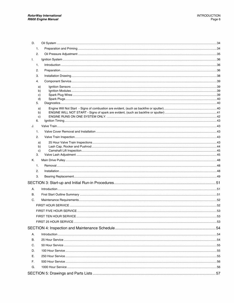
D. Oil System ............................................................................................................................................................................................ 34 1. Preparation and Priming ................................................................................................................................................................... 34 2. Oil Pressure Adjustment ................................................................................................................................................................... 35
I. Ignition System ..................................................................................................................................................................................... 36 1. Introduction ....................................................................................................................................................................................... 36 2. Preparation ........................................................................................................................................................................................ 36 3. Installation Drawing ........................................................................................................................................................................... 38 4. Component Service ........................................................................................................................................................................... 39
a) Ignition Sensors ........................................................................................................................................................................... 39 b) Ignition Modules ........................................................................................................................................................................... 39 c) Spark Plug Wires ......................................................................................................................................................................... 39 d) Spark Plugs .................................................................................................................................................................................. 40
5. Diagnostics ........................................................................................................................................................................................ 40 a) Engine Will Not Start - Signs of combustion are evident, (such as backfire or sputter) .............................................................. 40 b) ENGINE WILL NOT START - Signs of spark are evident, (such as backfire or sputter) ............................................................. 41 c) ENGINE RUNS ON ONE SYSTEM ONLY. ................................................................................................................................. 42
6. Ignition Timing ................................................................................................................................................................................... 43 J. Valve Train ............................................................................................................................................................................................ 43
1. Valve Cover Removal and Installation .............................................................................................................................................. 43 2. Valve Train Inspection ....................................................................................................................................................................... 43
a) 25 Hour Valve Train Inspections .................................................................................................................................................. 43 b) Lash Cap, Rocker and Pushrod ................................................................................................................................................... 44 c) Camshaft Lift Inspection ............................................................................................................................................................... 45
3. Valve Lash Adjustment ..................................................................................................................................................................... 45 K. Main Drive Pulley .................................................................................................................................................................................. 48
1. Removal ............................................................................................................................................................................................ 48 2. Installation ......................................................................................................................................................................................... 48 3. Bearing Replacement ........................................................................................................................................................................ 49
SECTION 3: Start-up and Initial Run-in Procedures ................................................................................................ 51 A. Introduction ........................................................................................................................................................................................... 51 B. First Start Outline Summary ................................................................................................................................................................. 51 C. Maintenance Requirements .................................................................................................................................................................. 52
FIRST HOUR SERVICE ............................................................................................................................................................................. 52 FIRST FIVE HOUR SERVICE .................................................................................................................................................................... 53 FIRST TEN HOUR SERVICE ..................................................................................................................................................................... 53 FIRST 25 HOUR SERVICE ........................................................................................................................................................................ 53
SECTION 4: Inspection and Maintenance Schedule ............................................................................................... 54 A. Introduction ........................................................................................................................................................................................... 54 B. 25 Hour Service .................................................................................................................................................................................... 54 C. 50 Hour Service .................................................................................................................................................................................... 55 D. 100 Hour Service .................................................................................................................................................................................. 55 E. 250 Hour Service .................................................................................................................................................................................. 55 F. 500 Hour Service .................................................................................................................................................................................. 56 G. 1000 Hour Service ................................................................................................................................................................................ 56
SECTION 5: Drawings and Parts Lists .................................................................................................................... 57

RotorWay International INTRODUCTION RI600 Engine Manual Page 7
A. Rotating Parts Assembly ...................................................................................................................................................................... 57 B. Main Drive Pulley Assembly ................................................................................................................................................................. 59 C. Crankcase Assembly ............................................................................................................................................................................ 60 D. Lower Cover Assembly ......................................................................................................................................................................... 61 E. Water Jacket Assembly ........................................................................................................................................................................ 63 F. Cylinder Head Assembly ...................................................................................................................................................................... 64 G. Plenum and Manifold Assembly ........................................................................................................................................................... 66 H. Fuel Shut-off Valve / Filter Assembly .................................................................................................................................................... 68 I. Electrical System .................................................................................................................................................................................. 69 J. Oil System ............................................................................................................................................................................................ 70 K. Gaskets and O-Rings ........................................................................................................................................................................... 71 L. Altitude Compensation Induction System ............................................................................................................................................. 72
SECTION 6: Hourly Service Chart ........................................................................................................................... 74

RotorWay International SECTION - 1 RI600 Engine Manual Page 8
SECTION 1: General Service Information
A. RI600 Engine Specifications Rated Horsepower @ 4250 RPM ................................................................................................................ 150 Torque @ 4250 RPM ........................................................................................................................... 185 ft.lb. Max Torque @ 3950 RPM ................................................................................................................... 191 ft.lb. Operational RPM (Calibrate with rotor RPM) ............................................................................................. 4250 Idle RPM ......................................................................................................................................... 1750 - 2000 Bore, inches ................................................................................................................................................ 4.00 Stroke, inches ........................................................................................................................................... 3.228 Displacement, cubic inches ......................................................................................................................... 162 Compression Ratio (Standard) .................................................................................................................. 9.4:1 Compression Ratio (ACIS Supercharger) .................................................................................................. 8.5:1 Flywheel Rotation (viewed from above) ............................................................................................. Clockwise Firing Order ...................................................................................................................................... 1 - 2 - 3 - 4 Ignition Systems (Dual-Independent) ................................................................................................. Electronic Ignition Timing .............................................................................................................. Variable 14°-38° BTDC Spark Plug Gap ............................................................................................................................ .040" - .044" Ignition Sensor/Timing Wheel Gap ........................................ 0.025" (both sensors within .004” of each other) Valve Lash Clearance ................................................................................................................... .004" - .006" Engine Dry Weight (includes main drive pulley, flywheel, water manifolds, dual ignition systems, and starter) ................................. 187 lbs.
NOTE: Measurements and adjustments must be made when the engine is cool and stable in temperature. See valve adjustment section.
B. Torque Requirements Main Drive Pulley Bolts 1 .................................................................................................................... 28 ft. lbs. Main Drive Flange Nut 1 ................................................................................................................... 200 ft. lbs. Cam Gear Bolts 2 ............................................................................................................................... 18 ft. lbs. Connecting Rod Bolts 3 ...................................................................................................................... 42 ft. lbs. Main Stud Nuts ................................................................................................................................... 40 ft. lbs. Cylinder Head Bolts (Final Torque Value) ........................................................................................... 22 ft. lbs. Intake Manifold Bolts........................................................................................................................... 15 ft. lbs. Exhaust Manifold Bolts ..................................................................................................................... 120 in. lbs. Polyloc Set Screws (Rocker Arms) ................................................................................................... 120 in. lbs. Ignition Sensor Bolts 1 ........................................................................................................................15 in. lbs. Oil Pressure Adjustment Plug 1 .......................................................................................................... 40 ft. lbs. Oil Pressure Adjustment Jam Nut ..................................................................................................... 108 in. lbs. Case Bolts .......................................................................................................................................... 15 ft. lbs. Starter Bolts ........................................................................................................................................ 18 ft. lbs. Starter Mount Bolts ............................................................................................................................. 15 ft. lbs. Lower Cover Bolts .............................................................................................................................. 15 ft. lbs. Oil Pump Cover Bolts.......................................................................................................................... 15 ft. lbs. Throttle Shaft Bearing Retention Bolt 1 ..............................................................................................15 in. lbs. Valve Cover Bolts ........................................................... see page 43 - Valve Cover Removal and Installation Knock Sensor ..................................................................................................................................... 16 ft. lbs.
Ignition Module Mounting Bolts ...........................................................................................................75 in. lbs. Throttle Position Sensor Bolts .............................................................................................................25 in. lbs. Plenum Cable Bracket Bolts ...............................................................................................................96 in. lbs. Fuel Rail Retention Bolts ....................................................................................................................96 in. lbs. Rocker Arm Studs 1 ........................................................................................................................... 40 ft. lbs. Spark Plugs 2 ..................................................................................................................................... 10 ft. lbs. Timing Wheel Bolts 1 ..........................................................................................................................96 in. lbs.
Cam End Plate ....................................................................................................................................96 in. lbs. 1 Install with service removable Loctite #242 2 Install with Loctite #271 3 All rod bolts should be thoroughly oiled before installing.
RotorWay International SECTION - 1 RI600 Engine Manual Page 9
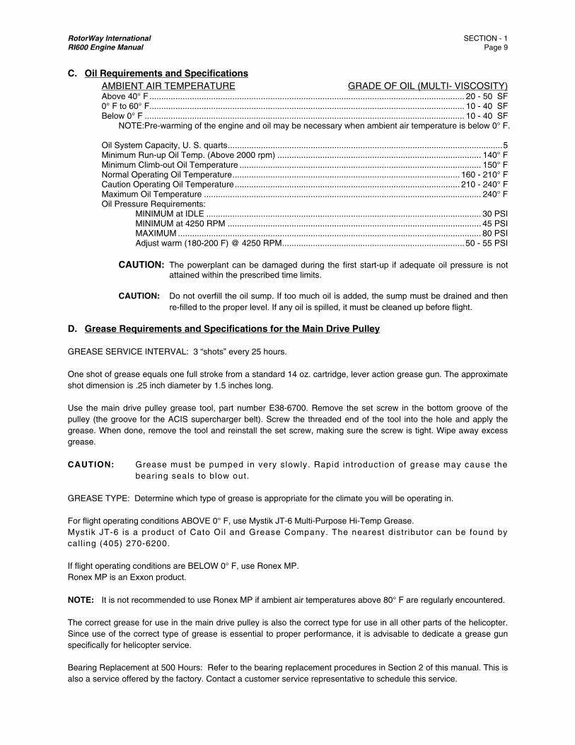
C. Oil Requirements and Specifications AMBIENT AIR TEMPERATURE GRADE OF OIL (MULTI- VISCOSITY) Above 40° F ..................................................................................................................................... 20 - 50 SF 0° F to 60° F ..................................................................................................................................... 10 - 40 SF Below 0° F ....................................................................................................................................... 10 - 40 SF NOTE:Pre-warming of the engine and oil may be necessary when ambient air temperature is below 0° F. Oil System Capacity, U. S. quarts .................................................................................................................... 5 Minimum Run-up Oil Temp. (Above 2000 rpm) ...................................................................................... 140° F Minimum Climb-out Oil Temperature ...................................................................................................... 150° F Normal Operating Oil Temperature ................................................................................................ 160 - 210° F Caution Operating Oil Temperature ............................................................................................... 210 - 240° F Maximum Oil Temperature ..................................................................................................................... 240° F Oil Pressure Requirements: MINIMUM at IDLE .................................................................................................................... 30 PSI MINIMUM at 4250 RPM ........................................................................................................... 45 PSI MAXIMUM ................................................................................................................................ 80 PSI Adjust warm (180-200 F) @ 4250 RPM ............................................................................. 50 - 55 PSI CAUTION: The powerplant can be damaged during the first start-up if adequate oil pressure is not
attained within the prescribed time limits.
CAUTION: Do not overfill the oil sump. If too much oil is added, the sump must be drained and then re-filled to the proper level. If any oil is spilled, it must be cleaned up before flight.
D. Grease Requirements and Specifications for the Main Drive Pulley
GREASE SERVICE INTERVAL: 3 “shots” every 25 hours. One shot of grease equals one full stroke from a standard 14 oz. cartridge, lever action grease gun. The approximate shot dimension is .25 inch diameter by 1.5 inches long. Use the main drive pulley grease tool, part number E38-6700. Remove the set screw in the bottom groove of the pulley (the groove for the ACIS supercharger belt). Screw the threaded end of the tool into the hole and apply the grease. When done, remove the tool and reinstall the set screw, making sure the screw is tight. Wipe away excess grease. CAUTION: Grease must be pumped in very slowly. Rapid introduction of grease may cause the
bearing seals to blow out. GREASE TYPE: Determine which type of grease is appropriate for the climate you will be operating in. For flight operating conditions ABOVE 0° F, use Mystik JT-6 Multi-Purpose Hi-Temp Grease. Mystik JT-6 is a product of Cato Oil and Grease Company. The nearest distr ibutor can be found by call ing (405) 270-6200. If flight operating conditions are BELOW 0° F, use Ronex MP. Ronex MP is an Exxon product. NOTE: It is not recommended to use Ronex MP if ambient air temperatures above 80° F are regularly encountered. The correct grease for use in the main drive pulley is also the correct type for use in all other parts of the helicopter. Since use of the correct type of grease is essential to proper performance, it is advisable to dedicate a grease gun specifically for helicopter service. Bearing Replacement at 500 Hours: Refer to the bearing replacement procedures in Section 2 of this manual. This is also a service offered by the factory. Contact a customer service representative to schedule this service.
RotorWay International SECTION - 1 RI600 Engine Manual Page 10
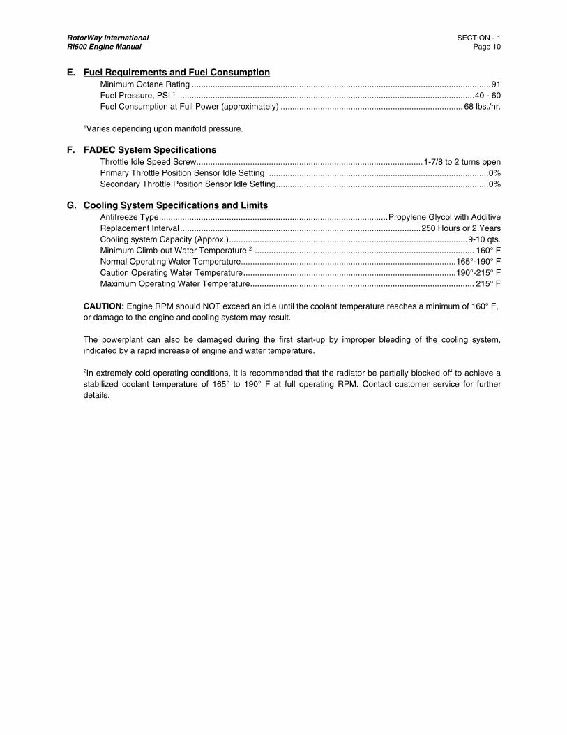
E. Fuel Requirements and Fuel Consumption Minimum Octane Rating ................................................................................................................................ 91 Fuel Pressure, PSI 1 .............................................................................................................................. 40 - 60 Fuel Consumption at Full Power (approximately) .............................................................................. 68 lbs./hr. 1Varies depending upon manifold pressure.
F. FADEC System Specifications Throttle Idle Speed Screw ................................................................................................. 1-7/8 to 2 turns open Primary Throttle Position Sensor Idle Setting .............................................................................................. 0% Secondary Throttle Position Sensor Idle Setting ........................................................................................... 0%
G. Cooling System Specifications and Limits Antifreeze Type .................................................................................................. Propylene Glycol with Additive Replacement Interval ....................................................................................................... 250 Hours or 2 Years Cooling system Capacity (Approx.) ...................................................................................................... 9-10 qts. Minimum Climb-out Water Temperature 2 .............................................................................................. 160° F Normal Operating Water Temperature............................................................................................ 165°-190° F Caution Operating Water Temperature ........................................................................................... 190°-215° F Maximum Operating Water Temperature ................................................................................................ 215° F CAUTION: Engine RPM should NOT exceed an idle until the coolant temperature reaches a minimum of 160° F, or damage to the engine and cooling system may result.
The powerplant can also be damaged during the first start-up by improper bleeding of the cooling system, indicated by a rapid increase of engine and water temperature. 2In extremely cold operating conditions, it is recommended that the radiator be partially blocked off to achieve a stabilized coolant temperature of 165° to 190° F at full operating RPM. Contact customer service for further details.
RotorWay International SECTION - 1 RI600 Engine Manual Page 11
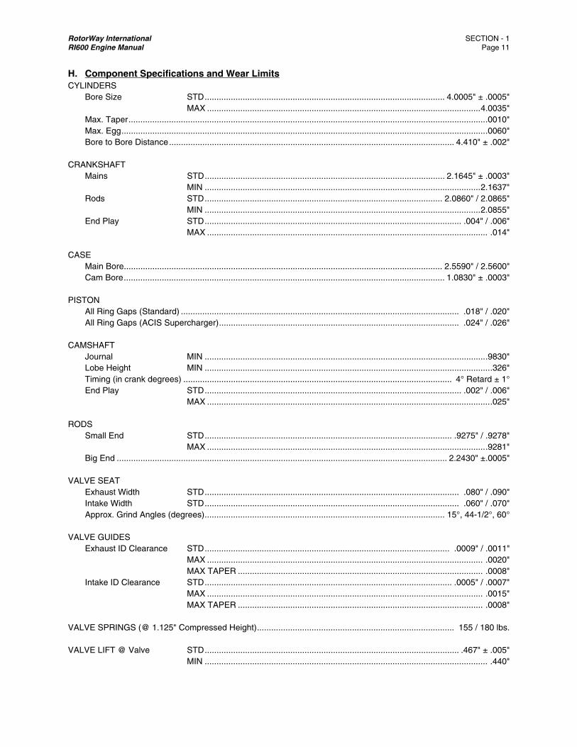
H. Component Specifications and Wear Limits CYLINDERS Bore Size STD ..................................................................................................... 4.0005" ± .0005" MAX ................................................................................................................... 4.0035" Max. Taper ...................................................................................................................................................... .0010" Max. Egg ......................................................................................................................................................... .0060" Bore to Bore Distance ........................................................................................................................ 4.410" ± .002" CRANKSHAFT Mains STD ..................................................................................................... 2.1645" ± .0003" MIN .................................................................................................................... 2.1637" Rods STD .................................................................................................... 2.0860" / 2.0865" MIN .................................................................................................................... 2.0855" End Play STD ............................................................................................................ .004" / .006" MAX ...................................................................................................................... .014" CASE Main Bore...................................................................................................................................... 2.5590" / 2.5600" Cam Bore ....................................................................................................................................... 1.0830" ± .0003" PISTON All Ring Gaps (Standard) ..................................................................................................................... .018" / .020" All Ring Gaps (ACIS Supercharger) ..................................................................................................... .024" / .026" CAMSHAFT Journal MIN ...................................................................................................................... .9830" Lobe Height MIN ........................................................................................................................ .326" Timing (in crank degrees) ................................................................................................................. 4° Retard ± 1° End Play STD ............................................................................................................ .002" / .006" MAX ....................................................................................................................... .025" RODS Small End STD ........................................................................................................ .9275" / .9278" MAX ..................................................................................................................... .9281" Big End ........................................................................................................................................... 2.2430" ±.0005" VALVE SEAT Exhaust Width STD ........................................................................................................... .080" / .090" Intake Width STD ........................................................................................................... .060" / .070" Approx. Grind Angles (degrees) ..................................................................................................... 15°, 44-1/2°, 60° VALVE GUIDES Exhaust ID Clearance STD ....................................................................................................... .0009" / .0011" MAX .................................................................................................................... .0020" MAX TAPER ....................................................................................................... .0008" Intake ID Clearance STD ........................................................................................................ .0005" / .0007" MAX .................................................................................................................... .0015" MAX TAPER ....................................................................................................... .0008" VALVE SPRINGS (@ 1.125" Compressed Height) ................................................................................... 155 / 180 lbs. VALVE LIFT @ Valve STD ........................................................................................................... .467" ± .005" MIN ....................................................................................................................... .440"
RotorWay IRI600 Engin
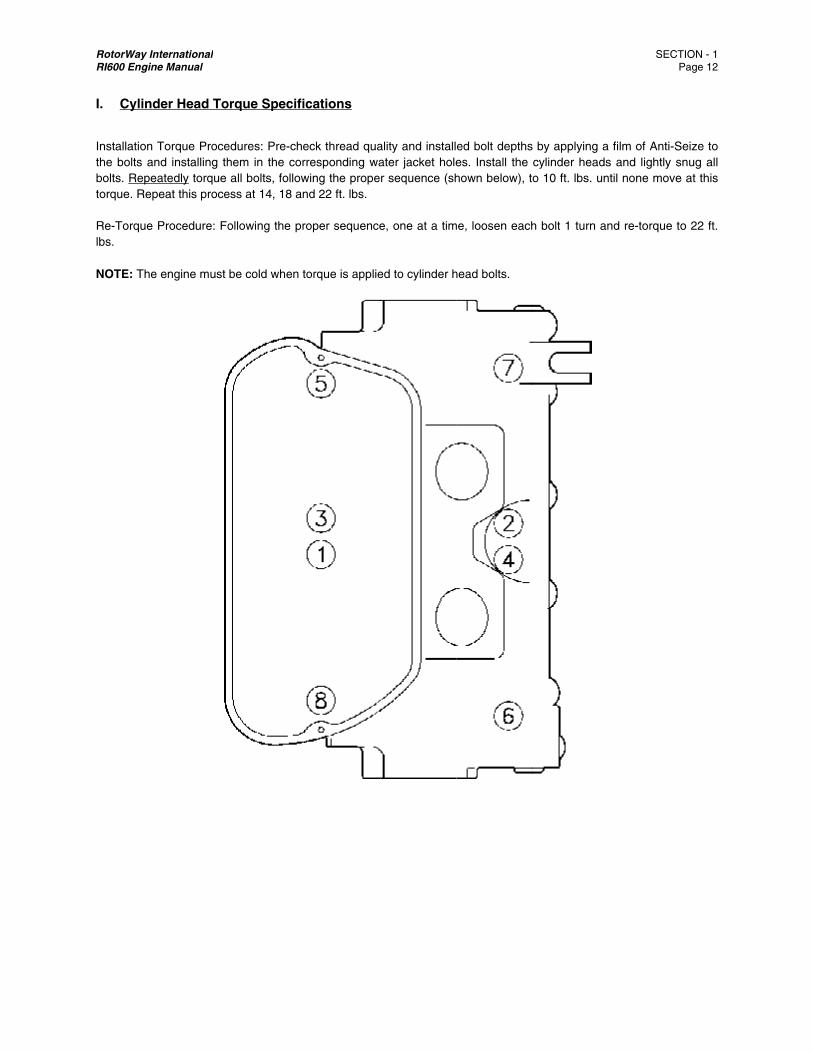
I. Cylin
Installationthe bolts abolts. Repetorque. Re Re-Torquelbs. NOTE: The
International ne Manual
der Head To
n Torque Proceand installing theatedly torque peat this proce
e Procedure: Fo
e engine must
orque Specifi
edures: Pre-chehem in the corall bolts, follow
ess at 14, 18 an
ollowing the pr
be cold when t
ications
eck thread quarresponding wawing the propend 22 ft. lbs.
roper sequence
torque is applie
ality and installater jacket holer sequence (sh
e, one at a tim
ed to cylinder h
ed bolt depthses. Install the hown below), t
me, loosen each
head bolts.
s by applying acylinder headso 10 ft. lbs. un
h bolt 1 turn an
SECT P
a film of Anti-Ses and lightly snntil none move
nd re-torque to
ION - 1 Page 12
eize to nug all at this
o 22 ft.
RotorWay International SECTION - 2 RI600 Engine Manual Page 13
SECTION 2: Individual System Procedures
A. Introduction Every basic system required for powerplant operation is covered individually within this manual. The following topics are addressed only in this section:
1. Correct Installation 2. Preparation For Start-Up 3. Initial Start-Up Procedures 4. Maintenance Procedures 5. Diagnostic Procedures
Read each section entirely, including the diagnostic procedures, as this will help provide an overview and insight leading to successful and long lasting powerplant operation.
B. Fuel System
1. Introduction
RotorWay helicopters are currently the only piston powered helicopters that utilize a fully redundant, electronic fuel injection system. Electronic fuel injection has long been the norm in the automotive industry, but unfortunately these automotive systems are not suitable for aviation use because they do not provide the required redundancy. General Aviation has not been in a position to make the change to electronics because of the extremely high costs involved in developing and certifying this type of system. The introduction of the RotorWay FADEC (Fully Automated Digital Electronic Control) System is the result of over four years of development and testing. It is a totally unique and customized system designed especially for use in RotorWay helicopters. It delivers fuel with extremely accurate air/fuel ratios. It automatically adjusts for changes in altitude, engine condition and outside temperature. Information regarding the system’s condition is clearly presented to the pilot via warning lights and a digital display screen. The FADEC System incorporates two separate and complete Engine Control Systems. Should the primary system become unable to properly control the engine, FADEC will automatically switch to the secondary or backup system. The primary system uses a sophisticated Engine Control Unit (ECU) to assimilate information from a number of primary and secondary sensors. It then delivers the proper fuel mixture based on these values. Primary sensors monitor two important engine conditions, RPM and Load. These values are essential elements in computing and delivering an accurate air/fuel ratio. FADEC “backs up” both primary sensors through specific ECU programming. Although only one RPM value is needed by the ECU, duplicate values are constantly monitored from each of the independent ignition systems. For load value, the ECU uses information from a MAP (Manifold Pressure). Should this sensor fail, the secondary system will take over. This additional redundancy also applies to the barometric and air temperature sensors that both primary and secondary systems have. Secondary sensors are not essential for engine operation while operating on the primary system. The ECU for the secondary system is capable of adjusting for altitude and temperatures the same as the primary ECU. Should both primary and secondary sensors fail, the ECUs are programmed to revert to preset default values. The loss or intermittent failure of any sensor will be brought to the pilot’s attention via a red blinking warning light on the instrument panel.
RotorWay International SECTION - 2 RI600 Engine Manual Page 14
In the unlikely event that the MAP sensor fails or if a green FADEC primary light turns off and a red light turns on there is a Main ECU loss or malfunction, FADEC will automatically transfer control of the engine to the secondary system. A red warning light will illuminate on the instrument panel to inform the pilot of the deactivation of primary system. This “back up” is an independent system with its own ECU and MAP sensor. WARNING: Although the pilot has the ability to manually activate the secondary engine control system by turning off the primary switch on the overhead panel, this system is not intended to be used as a regular means of engine control. The pilot should carefully land at the nearest safe site if the secondary system activates. While the inner workings of the FADEC System are sophisticated and rather complex, the skills and tools needed to service the system are not. If you carefully follow all of the procedures contained in this section of the manual, you should have no difficulty understanding and maintaining the FADEC system. It is important to note that 99% of all problems with electronic engine control systems are wiring related. These problems include damaged wiring and faulty or loose connectors. Pay special attention to these components during construction and maintenance of the helicopter. It is important for you to understand the FADEC system and the following procedures. This knowledge is essential for you to properly construct, maintain and fly the helicopter. If you have questions about the FADEC system or if you are unclear about any of the procedures, please call our customer service department.
2. Fuel Requirements
The RI 600 powerplant is designed to burn premium unleaded or leaded automotive gasoline which has a minimum octane rating of 91. Use only gasoline from a known major brand station which has fuel specially formulated for fuel injection, such as Mobil, Texaco, Arco, etc. 100 low lead aviation gasoline may also be used. NOTE: Regular maintenance includes rebuilding the cylinder heads at 500 hours if unleaded fuel is used. This is reduced to 250 hours if using 100 low lead or leaded automotive gasoline. Do not attempt to use old gasoline because it may not deliver the required performance. In addition to possible moisture contamination, gasoline volatility is adjusted by the suppliers seasonally and geographically to reduce the chance of problems. 5-10% alchol content is ok to use.
3. Preparation
WARNING: This fuel system is designed to operate at pressures up to 60 PSI. A fuel leak in this system could cause a fire or even an explosion. If you do not completely understand any of the following procedures please call customer service for additional assistance. CAUTION: DO NOT connect the battery, put gasoline in the fuel tanks or turn on the fuel pumps until advised to do so during these procedures.
A. Review the plans to ensure that the proper routing and attachment of all fuel system components is correct. This includes fuel hoses, wiring and all individual components such as filters, pressure regulator, shut-off valve, etc.
B. Inspect all of the installed fuel hoses and make certain that you have complied with the following general rules:
1. Make sure that there is adequate clearance between the hose ends and anything they might be able to contact.
While the hose is flexible, the hose ends are not.
2. Do not allow a hose to contact a sharp corner, nut, bolt, rivet stem or anything else that might cause damage.
RotorWay International SECTION - 2 RI600 Engine Manual Page 15
3. Do not allow a hose to rub against anything, even if the surface on which it rubs is flat. The stainless steel braid is a very efficient low speed file and will abrade through anything that it moves against. In order to prevent chafing and to keep your hoses where you want them, support the hoses with wire ties or cushion loop clamps.
4. Do not force the hoses to bend too tight. Do not kink the hose, either by bending too tight, by misalignment
between the hose end and fitting on short assemblies, or by getting the whole assembly into a helix on long assemblies.
5. Check tightness of all fuel hoses. Do not over-tighten the hose ends onto the adapter fittings. The seal is
achieved by the design of the mating surfaces, not by muscle. If it leaks, it has probably been assembled incorrectly. Damage to the cone and seat can be caused by various mistakes on assembly, the most common of which are dirt and over-tightening.
C. Prepare for the inspection of FADEC System components by carefully adhering to the following procedures.
1. At the starter, disconnect the wire between the starter and the starter relay. Insure that this wire can not short
against anything when the battery is eventually connected. This is done to protect against an inadvertent start of the powerplant and to allow a later testing of the starter relay.
2. Inspect the routing, security and condition of the FADEC wiring harness. It must be well supported and not
allowed to chafe against any other component. Wires should not be pulled tight or radically bent. Connector plugs should be secured and not allowed to vibrate excessively. All plugs should be checked for proper connection (locking tabs engaged).
NOTE: Before installing a connector, inspect for any debris or damage inside the plug and make sure that the pins
are straight. Confirm that the weather-tight seals are in place on plugs that are equipped with them. You should never have to force a plug together. This would be an indication of a broken plug, misaligned seal or a damaged pin.
3. Connect the battery. First make sure that all of the overhead switches are off. It is also a good practice to verify
that there is not a short in the system before connecting the battery for the first time. This can be accomplished by using an ohm meter between the positive and negative battery cables.
NOTE: During the following initial testing, if any of the switches fail to function properly, use the appropriate wiring
harness schematic to troubleshoot the problem. Using a volt meter, check for power at the switch and at the line termination point to determine if the problem is the wiring or a part. If a switch is incorrectly wired, (it performs the wrong function), trace the wire through the harness to determine if a pin has been incorrectly positioned in a plug.
WARNING: Do NOT attempt to disassemble any FADEC connector plug without first contacting Customer
Service. Special tools and procedures must be used on these parts to prevent damage and possible component failure. Handling of circuit boards can cause damage from static discharge.
D. Test the fuel pumps for proper operation by turning the switches on and off, one at a time. You should be able to hear
a pump when it is operating. Run the pumps for as short a time as possible since running a pump dry can cause damage. By feeling the body of a pump you can tell if it is running or not. Each switch should operate one and only one pump.
E. Test the fuel pump inertia switches. This is accomplished by unbolting an inertia switch, holding it upright in one hand
and striking it sharply with the other hand. Turn on the corresponding fuel pump switch. The fuel pump should remain OFF. (This can be verified by checking the fuel pressure gauge.) Reset the inertia switch by pushing downwards on
RotorWay International SECTION - 2 RI600 Engine Manual Page 16
the top of the switch. This should cause the fuel pump to turn on. Turn off the fuel pump switch and re-bolt the inertia switch to the bracket. Test the other inertia switch in the same manner.
F. Test the ignition switches. Begin by disconnecting plugs numbered 28 and 29 on the FADEC wiring harness. These
plugs attach to the 4 pin receptacles of the ignition modules. Turn the switches on and off, one at a time, and verify voltage to pin D. The switches should remain off after testing. Do not reconnect plugs 28 and 29 at this time.
G. ARM the FADEC System. Refer to the A600 Talon Pilot Operating Handbook and follow the detailed procedures.
Turn each FADEC switch on and off, one at a time, to insure that each provides an independent source of power. The green and red light on the instrument panel should indicate which system is operating. If any problems are encountered, refer to the diagnostic section under ARM FADEC.
H. Test the operation of the starter relay. DO NOT engage the starter at this time. Connect a volt meter between the
frame ground and the previously disconnected relay wire. Turn on the instrument switch and the key. Engage the starter button. The meter should indicate 12 volts. Turn off the key and verify lock out of the starter circuit. Turn off all switches. Reconnect the starter relay wire to the starter. DO NOT crank the engine at this time. If a problem is encountered use the wiring schematic and a volt meter to resolve it.
I. Test the fuel system for leakage. Read the Preface in Section 20 of the Construction Manual. Carefully observe the
following procedures:
CAUTION: DO NOT perform the following test until the helicopter is ready for the first start up. Have a fire extinguisher by the helicopter and wear eye protection. If you have a leak, the pressure of this system can cause fuel to be sprayed surprisingly far and fast.
1. Put a total of three to four gallons of fuel in the fuel tanks. This is adequate for testing and for the initial start of
the helicopter. Turn on the fuel valve. Turn on the instruments. Turn on one fuel pump and check for leaks. Immediately turn off the fuel pump and fuel valve if a leak is detected. Repair the leak.
WARNING: If a leak is found, pressure will remain in the system AFTER the pumps and valve have been turned off.
SLOWLY disconnect the hose at the spot of the leak and be prepared for fuel to spray from the connection.
2. Turn on the second pump. Carefully re-check for leaks. One good way to check for small leaks is to run a clean
finger around all of the connections on the fuel system. Even a small drop can be found using this procedure. (Smelling the drop should verify if it is fuel or simply oil used during the installation process.) We stress the importance of this inspection because A FUEL LEAK ON THIS SYSTEM CAN BE EXTREMELY DANGEROUS! Even the smallest leak can develop into a large one in a system operating at high pressure.
NOTE: Fuel is constantly being pumped in a circle when the pumps are running. (Gasoline is being returned to the
fuel tank continuously.) The sounds which the fuel pumps make will change as the air is removed from the system. If you turn off the fuel valve when the pumps are running you will hear the sound change. This sound change is the result of the restriction on the inlet of the pumps. DO NOT OPERATE THE PUMPS WITH THE FUEL VALVE OFF.
3. The fuel pressure gauge should be reading approximately 55 PSI. Production differences between gauges,
pressure senders and pressure regulators can cause a variance in the indicated pressure of up to 5 PSI. There should be a 1 to 3 PSI difference in pressure between operation with one and two pumps. The pressure regulator is designed to maintain a steady differential pressure between the fuel rails and the intake manifold. You should notice a decrease in the indicated fuel pressure when the motor is started and develops a vacuum in the intake manifold.
RotorWay International SECTION - 2 RI600 Engine Manual Page 17
4. After the initial leak testing is complete, turn off all switches and turn off the fuel valve. CONTINUE TO
REGULARLY INSPECT THE FUEL SYSTEM FOR LEAKAGE. This is especially important during the first few hours of operation and during each pre-flight inspection!
M. Carefully connect the ignition modules. Install the seat back panel and check the security of the wiring. Arm the
FADEC System to test for proper re-connection of the components. Turn off all switches and verify that the fuel valve is off.
N. Before starting the helicopter for the first time, perform all procedures relating to “Preparation” in the Cooling, Oil and
Ignition Sections of this Manual.
O. During the “First Hour Service” in Section 3, you will be instructed to perform an additional inspection on the FADEC System. This inspection can only be accomplished when the engine is running.
4. Component Service
a) Injectors Maintenance is not normally required on these components. If a problem should develop which requires injector
replacement, refer to the following service procedures. INJECTOR PART # MFG. MFG. NUMBER RESISTANCE (ALL) A24-5530 AC Delco 12561462 12.5 OHMS GM 0-280-155-931 TESTING: Carefully remove the connector plug from the injector. Use an ohm meter to measure the resistance between
the two terminals of the injector. Compare this value against the injector’s specified resistance. We recommend replacing an injector if the resistance reading is incorrect and you suspect that it is not properly delivering fuel. Comprehensive testing and cleaning of injectors can only be accomplished using special equipment. The flow rate and the spray pattern must be measured and analyzed to determine if the injector is performing according to all specifications.
REMOVAL: Carefully bleed off the fuel pressure and drain the fuel from the fuel rail assembly. Disconnect both fuel lines from the fuel rail and remove the retention bolts. Support the injectors to keep them from falling out of the fuel rail. Withdraw the parts collectively by moving them from side to side while pulling the injectors out of the intake manifold. Carefully remove the injectors from the fuel rail with the same wiggling motion.
REPLACEMENT: Clean the fuel rail and inspect its injector bores. These bores must have a good finish and be free of scratches. If an injector is being reused, the O-rings must be replaced. Before installing the injectors, apply a light film of engine oil to the O-rings and to the bores into which the injectors will be inserted. Install both injectors in the fuel rail by pushing them into the bores while wiggling them from side to side. Install this assembly into the plenum bores using the same wiggling motion. Install and lightly snug the retention bolts. The fuel rail bolt holes are large enough to allow adjustment of the final mounting position. The alignment of the injectors must not be binding. Injectors must have clearance to easily move up and down in the bores. Once this alignment is correct, torque the bolts and safety wire them.
b) Air and Water Temperature Sensors
These sensors require no maintenance. Testing is accomplished by using an ohm meter to measure the resistance across the two terminals. Resistance at room temperature is approximately 2500 ohms. The value will vary with temperature. A failure of these components will normally result in an “open line” or a zero ohm condition.
RotorWay IRI600 Engin
c) BaromThesepressuexceptaccomsenso
d) Prima
Theseharnes
CAUT
The msensohelp y
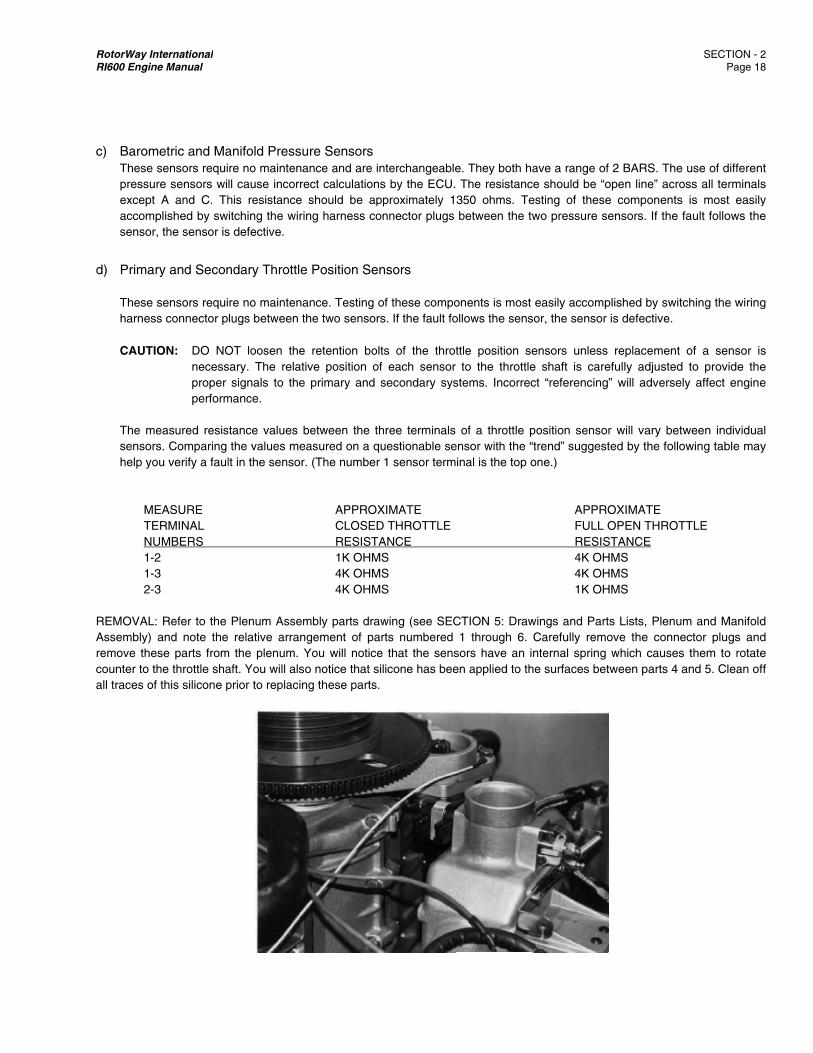
M TE N 1- 1- 2- REMOVALAssembly) remove thecounter to all traces o
International ne Manual
metric and Mae sensors requiure sensors wit A and C. Th
mplished by swr, the sensor is
ary and Secon
e sensors requiss connector p
TION: DO NOnecessproper perform
measured resisrs. Comparing ou verify a faul
MEASURE ERMINAL UMBERS -2 -3 -3
L: Refer to the and note the
ese parts fromthe throttle sha
of this silicone p
anifold Pressure no maintenall cause incorrehis resistance itching the wiri
s defective.
ndary Throttle
re no maintenalugs between t
OT loosen thesary. The relat
signals to themance.
stance values bthe values me
lt in the sensor
Plenum Assem relative arran
m the plenum. Yaft. You will alsprior to replacin
ure Sensorsance and are inect calculationsshould be ap
ing harness co
e Position Sen
ance. Testing othe two sensors
e retention boltive position ofe primary and
between the theasured on a qr. (The number
APPROXCLOSEDRESISTA1K OHM4K OHM4K OHM
mbly parts drangement of paYou will noticeo notice that si
ng these parts.
nterchangeables by the ECU.
pproximately 1onnector plugs
nsors
of these compos. If the fault fo
ts of the throtf each sensor secondary sys
hree terminals uestionable se1 sensor term
XIMATE D THROTTLEANCE S S S
wing (see SECrts numbered
e that the sensilicone has bee
e. They both haThe resistanc
350 ohms. Tebetween the tw
onents is most ollows the sens
ttle position seto the throttle
stems. Incorrec
of a throttle pensor with the “inal is the top o
CTION 5: Draw1 through 6.
sors have an ien applied to th
ave a range ofce should be “oesting of thesewo pressure se
easily accompsor, the sensor
ensors unless e shaft is carect “referencing
position senso“trend” suggestone.)
APPROFULL ORESIS4K OH4K OH1K OH
wings and PartCarefully remonternal spring
he surfaces bet
f 2 BARS. The open line” acroe components ensors. If the f
plished by switcis defective.
replacement efully adjusted ” will adversel
r will vary betwted by the follo
OXIMATE OPEN THROT
STANCE HMS HMS HMS
ts Lists, Plenumove the connewhich causes
tween parts 4 a
SECTION - 2 Page 1
use of differenoss all terminals
is most easilyfault follows the
ching the wiring
of a sensor ito provide the
y affect engine
ween individuaowing table may
TTLE
m and Manifoldector plugs and them to rotateand 5. Clean of
2 8
nt s y e
g
s e e
al y
d d e ff
RotorWay International SECTION - 2 RI600 Engine Manual Page 19
REPLACEMENT: While it is not essential that the plenum assembly be removed from the engine compartment, removal will simplify the sensor adjustment process and make safety wiring of the sensor retention bolts easier. NOTE: Replacement of throttle position sensors is a service offered by the factory. Please call Customer Service to schedule
this work. Check the fit of each sensor on the throttle shaft. They MUST slide easily on the shaft. De-burring of the sensor slot may be necessary. Be careful not to damage the sensors by allowing dirt to contaminate the internal rotating components. Final assembly of the throttle position sensors requires a bead of silicone to be applied to the area around the protruding ring of the TPS Spacer. The silicone will form a seal between the secondary throttle position sensor and the TPS spacer. This is done to prevent moisture contamination of the sensor. Since it is important to insure that the inside of the sensor assembly does not become contaminated, silicone must be applied only to the area outside of the protruding ring of the TPS Spacer. NOTE: The replacement process is an important and tedious procedure. We suggest that you practice the sensor installation process before applying silicone to the parts for the final assembly. Install all of the components on the throttle shaft. Lightly snug the retention bolts after positioning the sensors in the center range of their travel. (The bolts must be loose enough to allow adjustment of both sensors.) Install the primary and secondary connector plugs onto the proper throttle position sensors. Insure that the throttle is at idle and that the throttle return spring is attached. Adjust the position of each throttle position sensor to meet all of the following conditions:
1. With the primary system engaged, the digital display monitor indicates a throttle position of 0.0%.
2. When a .002" feeler gauge is placed between the throttle stop roll pin and the throttle stop arm, (partially opening the throttle), the indicated throttle position is 0.5% to 1.0%.
3. After disconnecting the throttle return spring, the throttle shaft moves freely with no evidence of binding. It should
easily return to the idle stop using only the self contained springs of the throttle position sensors.
4. Repeat the above steps for secondary TPS sensors, or by reading secondary values on display. Torque the sensor retention bolts to 25 in. lbs. This additional tightening of the bolts may cause the sensor adjustment to change. Verify that ALL of the preceding conditions are still satisfied. Re-adjust the sensor positions if necessary. Once proper sensor adjustment has been verified, safety wire the retention bolts. If the plenum was removed to facilitate replacement, re-install the plenum and carefully leak check the fuel system before starting the powerplant.
e) Throttle Shaft Assembly Maintenance is not normally required on this component. The replacement of this component is a service offered by the Factory. Please contact Customer Service to schedule this service. REMOVAL AND REPLACEMENT: The plenum must be removed from the engine. All components must be removed from the throttle shaft. The throttle shaft bearings are Loctited into the plenum and onto the throttle shaft. The plenum must be warmed to 250° F before attempting to remove the shaft and bearings. The air temperature sensors must be removed from the plenum before heating. Do not exceed 275° F or you will damage the heat treatment of the aluminum. During the replacement process these bearings must be loctited. The Loctite must be allowed to “set” with the butterfly installed and with the shaft placed in the
RotorWay International SECTION - 2 RI600 Engine Manual Page 20
fully closed position. The shaft must then rotate with no binding or drag. All other components are then replaced. Be careful to accurately adjust the “full open” and “idle” positions of the throttle. Carefully follow the procedure for throttle position sensor replacement. Failure to adjust these settings accurately will cause serious damage to the engine. Install the plenum and leak test the fuel connections prior to starting the engine.
f) Air Filter The air filter must remain clean in order to maintain proper engine performance. A common cause of power loss is a clogged or dirty air filter. A restrictive air filter will cause the engine to operate in an overly rich condition which could cause engine damage! If the air filter appears dirty or if it has been contaminated with grease, cleaning and re-oiling is required. If any damage is evident or if it can not be properly cleaned, replace the air filter. Certain local conditions may warrant an inspection and cleaning on a more regular basis than the 25 hour interval recommended in this manual. CAUTION: Use ONLY “K&N” brand air filter oil and cleaning agent. CLEANING: Lightly brush and tap off any surface dirt. (Heavy brushing will damage the gauze.) Pour the K&N cleaning agent into a “paint-tray” type pan. Roll the filter in the solution to dissolve and detach the grease and dirt. Keep the level of the cleaning solution in the pan low enough so that the inside of the filter does not become contaminated. Rinse the filter with cold water from the INSIDE outward. Shake the filter to remove as much water as possible and then allow it to air dry. Do NOT attempt to accelerate the drying process by using compressed air to blow through the filter. This WILL damage the air filter! OILING: Holding the spray can approximately 3" away from the filter, make one pass along each pleat. Allow twenty minutes for the oil to spread and dry. Do not oil the filter twice. If the oil is properly applied, the filter’s gauze should appear red, have no white spots and be “dripless”.
g) Fuel Pump Maintenance is not normally required to be performed on this component. One fuel pump will always produce 2 to 4 PSI less pressure than both pumps will produce when operating simultaneously. Check both fuel filters for contamination before assuming that the fuel pump, or pumps, are responsible for low fuel pressure. If a pump fails to operate, check the fuse and check for power and “ground” at the pump. If it is necessary to replace a fuel pump, turn off all of the switches and disconnect the wiring before removing the fuel hoses. After replacing a fuel pump, carefully leak check the fuel system before starting the engine.
h) Fuel Filter The fuel filter should be replaced prior to the recommended interval if your fuel quality is questionable or if lower than normal fuel pressure is encountered. The inlet and outlet fittings on the fuel filter are reusable. The two crush washers must be replaced during each filter change. After changing the fuel filter, always leak check the fuel system before starting the engine.
i) Fuel Shut-Off Valve/Filter Assembly Refer to the parts drawing in Section 5 for the detailed breakdown of this component. It will be necessary to carefully drain the fuel tanks to service the entire assembly. However, with the shut-off valve in the off position, the filter can be serviced without draining the tank. SERVICE FILTER: Have a fire extinguisher nearby. Position an appropriate container under the helicopter and fabricate a tray to direct any spilled fuel into the container. Hold fitting #15 with a wrench and disconnect the fuel hose. Be prepared for fuel to come out of the assembly at this time. Hold fitting #16 with a wrench and remove fitting #14. The fitting should loosen with a
RotorWay International SECTION - 2 RI600 Engine Manual Page 21
minimum amount of force, but be careful not to damage the assembly. Remove items numbered 10, 11 and 12. Carefully clean the filter and the inside diameter of the housing. If there is a large amount of debris trapped in the filter, this would be an indication that more frequent service is required. Inspect and replace both O-rings as necessary. Place a film of oil on the O-rings and a generous amount of oil on the threads of fitting #14 and in the tapered section of the housing bore. Carefully replace all components. Do not over tighten Fitting #14. The seal is made by the O-ring and NOT by how tight the fitting is secured. Over tightening can result in damage to the assembly. Re-connect the hose to fitting #15 and carefully leak check the system prior to starting the engine. SERVICE SHUT-OFF VALVE: Service is not required unless a fuel leak develops around the O-rings. All fuel must be drained from the fuel tanks in order to service this component. Remove the lower snap ring from the shut-off rotor and carefully remove the valve assembly. Prior to replacement of the assembly, apply a film of oil to the O-rings and to the bore of the housing. It is very important to align the shut-off arm with the shut-off rotor so that when placed in the OFF position, the bore of the rotor is perpendicular to the main bore of the housing. This is necessary to maintain a proper seal in the OFF position. Carefully leak check the system prior to starting the engine.
j) Engine Control Unit This component is NOT serviceable by anyone other than RotorWay International. DO NOT attempt to disassemble the ECU. DO NOT perform any resistance or voltage checks on the ECU. Call the Factory if you find or suspect that there is a problem with this component.
k) Secondary Engine Control Unit Like the main ECU, this component is NOT serviceable by anyone other than RotorWay International. DO NOT attempt to disassemble or perform any resistance or voltage checks on this component. Call the Factory if you find or suspect that there is a problem. WARNING: Handling of circuit boards may cause damage from static discharge.
l) Fuel Pump Inertia Switches This component should not require any maintenance. When these switches were initially installed they should have been tested to verify proper function. If a switch is found to be defective it must be replaced with an identical type switch which is available from RotorWay International. TESTING: Leave the wiring plug connected and remove the switch from the mount. Insure that the switch is “set” by pushing downward on the top of the switch. Turn on the corresponding fuel pump and hold the switch upright in one hand. Strike the switch sharply with your other hand. The switch should operate and stop the fuel pump. Reset the switch and repeat the test. Re-mount the switch on the bracket and turn on the corresponding fuel pump. With a rubber mallet, hit the bracket to which the switch is mounted. The switch should NOT stop the fuel pump during this test. If a switch fails either of these tests it should be replaced.
m) Engine Coolant Temperature (ECT) sensor, and Intake Air Temperature (IAT) sensor These sensors use a thermistor to control the signal voltage to the ECM. The ECM applies 5 volts to the sensor. When the engine temp is cold, sensor resistance is high. As temperature increases sensor resistance decreases.
RotorWay International SECTION - 2 RI600 Engine Manual Page 22
n) Manifold Absolute Pressure (MAP) sensor This sensor responds to changes in manifold pressure. The ECM receives this information as a signal voltage that will vary from about 1.0 - 1.5 volts at idle to about 4.0 - 4.5 volts at wide open throttle (WOT).
o) Throttle Position (TP) Sensor This sensor is a potentiometer that provides a voltage signal that changes relative to the throttle blade. Signal voltage should vary from about 0.7 volt at idle to about 4.8 volts at wide open throttle (WOT).
p) Knock Sensor These sensors are used by the ECM to detect engine detonation. This detection allows the ECM to retard spark timing based on the knock sensor signal coming into the ECM. If knock sensor wires are routed too close to secondary ignition wires, the ECM mat see the interference as a knock signal, resulting in false timing retard.
5. Diagnostics
a) Introduction If a problem occurs with the FADEC System, it is important to proceed in a manner which will positively identify the problem. Read the diagnostic section that deals with the specific problem which you have encountered. If the primary or secondary red ECU light is blinking there is a problem with that FADEC sysem. On screen number 6 of the glass display the trouble code can be viewed for the primary or secondary system. If you feel that there is a problem with the FADEC System that is not identified in any of the above diagnostic sections, you should inspect the following:
1. The air filter for contamination. 2. The spark plugs for fouling. 3. The spark plug wires for damage. 4. The fuel injectors for malfunction. 5. The fuel for contamination.
Normal FADEC operation is as follows:
1. With the engine off. 2. Turning on FADEC 1 will flash the green FADEC light once. 3. That will be followed by a flash of the yellow caution light. 4. Finally the red FADEC light will illuminate. 5. This procedure is to check that the lights are working correctly. 6. When turning on FADEC 2 the same sequence can be observed with the FADEC 2 lights. 7. If the switch is switched on and off rapidly you may not get the yellow and red lights. This is normal. 8. These lights will not stay if the engine is not running. 9. Once the engine is started with both FADECs on both FADEC green lights should be illuminated.
WARNING: Contact Customer Service if you have any questions about the FADEC System. Do not continue to operate the
engine if a problem is indicated or suspected. Even if the engine appears to operate properly, system failure or engine damage could be imminent.
b) FADEC Power Supply
RotorWay International SECTION - 2 RI600 Engine Manual Page 23
The FADEC System uses relays to automatically switch two sources of power between the primary ECU controlled system and the secondary system. If a problem is encountered, refer to the Wiring Guides and to the suggested test sequence in order to locate and correct the problem. SUGGESTED TEST SEQUENCE:
1. Test for 12 Volts Switch Power In @ PLUG #10 A and B Primary ECU Power In @ PRI J2 Plug 2-19 Secondary ECU Power In @ SEC J2 Plug 4-19 Green Light + Out @ Plug #12 E
2. Test for Ground @ PRI J1 Plug 1-13, 28, 29 @ PRI J1 Plug 3-13, 28, 29
c) Secondary System Operation The secondary system should activate in all of the following conditions: 1. If FADEC 2 switch is turned on first. 2. If the primary ECU has a power loss or fails. 3. Internal ECU voltage fluctuations. This is checked by a “watch dog” circuit which is built into the ECU.
d) Wiring and Connector/Plug Faults These types of faults can be the most difficult problems to locate. They can be caused by a damaged terminal, a loose wire or a broken wire. If the sensor involved with the problem checks good, and the fault is intermittent, you should individually wiggle each connector/plug in the harness that transmits the signal from the sensor. This may enable you to pinpoint the specific location of the problem. Use an ohm meter to find the exact spot of the fault. If plugs were improperly handled, pin damage may have occurred. Disassemble the connector and carefully examine the pins in question. If the main FADEC wiring harness becomes damaged you should call RotorWay Customer Service to discuss the repair. We do not recommend that you attempt pin replacement in these harnesses because special tools and techniques are required to properly complete the assembly.
e) Fuel Pressure Irregularities The fuel pressure gauge should read approximately 55 PSI. Production differences between gauges, pressure senders and pressure regulators can cause a variance in the indicated pressure of up to 5 PSI. There should be a 1 to 3 PSI difference in pressure between operation with one and two pumps. You should record what the “normal” indicated fuel pressure is in your helicopter with both fuel pumps on before you start the engine. This value may be slightly lower with warm fuel than with cold fuel. If the fuel pressure becomes significantly lower than “normal”, it is an indication that the fuel inlet or outlet filters have become plugged or it is an indication that the fuel pressure regulator is damaged. The important thing is to look for an “indicated” fuel pressure value which is out of the “normal” range. This is true for all operating pressure ranges. The pressure regulator is designed to maintain a steady “differential” pressure between the fuel rails and the intake manifold. You should notice a decrease in the indicated fuel pressure when the engine is started and develops a vacuum in the intake manifold. The pressure should decrease by approximately 1/2 PSI for each 1 inch decrease in manifold pressure. If the fuel pressure does not decrease as the manifold pressure decreases, there is a problem with the fuel pressure regulator or with the hose which connects it to the plenum.
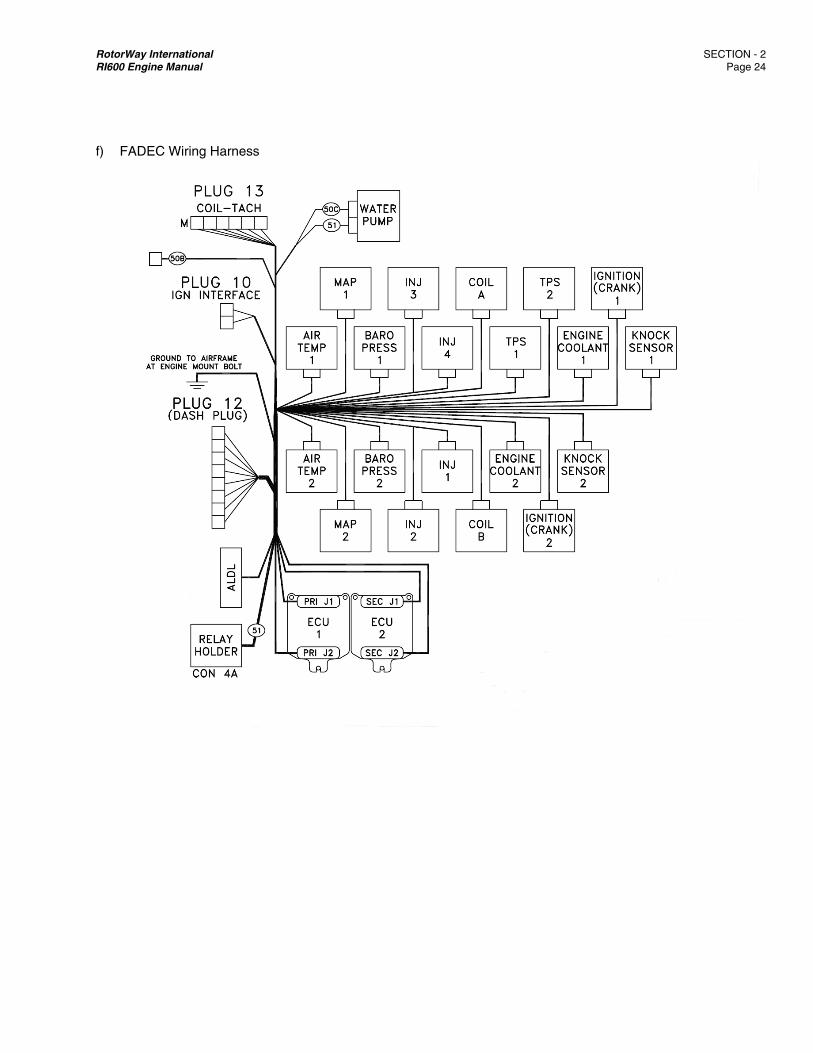
RotorWay International SECTION - 2 RI600 Engine Manual Page 24
f) FADEC Wiring Harness
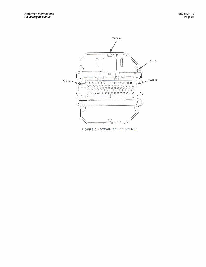
RotorWay International SECTION - 2 RI600 Engine Manual Page 25
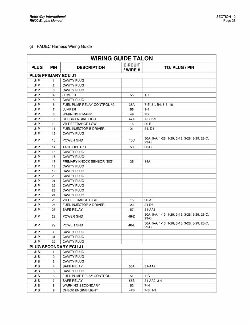
RotorWay International SECTION - 2 RI600 Engine Manual Page 26
g) FADEC Harness Wiring Guide
WIRING GUIDE TALON
PLUG PIN DESCRIPTION CIRCUIT / WIRE # TO: PLUG / PIN
PLUG PRIMARY ECU J1 J1P 1 CAVITY PLUG
J1P 2 CAVITY PLUG
J1P 3 CAVITY PLUG
J1P 4 JUMPER 55 1-7
J1P 5 CAVITY PLUG
J1P 6 FUEL PUMP RELAY CONTROL #2 35A 7-E, 31, B4, 6-8, 10
J1P 7 JUMPER 55 1-4
J1P 8 WARNING PIMARY 49 7D
J1P 9 CHECK ENGINE LIGHT 47A 7-B, 3-9
J1P 10 VR REFERANCE LOW 16 20-B
J1P 11 FUEL INJECTOR B DRIVER 21 31, D4
J1P 12 CAVITY PLUG
J1P 13 POWER GND 46C 30A, 5-A, 1-28, 1-29, 3-13, 3-28, 3-29, 28-C, 29-C
J1P 14 TACH OPUTPUT 53 33-C
J1P 15 CAVITY PLUG
J1P 16 CAVITY PLUG
J1P 17 PRIMARY KNOCK SENSOR (SIG) 25 14A
J1P 18 CAVITY PLUG
J1P 19 CAVITY PLUG
J1P 20 CAVITY PLUG
J1P 21 CAVITY PLUG
J1P 22 CAVITY PLUG
J1P 23 CAVITY PLUG
J1P 24 CAVITY PLUG
J1P 25 VR REFERANCE HIGH 15 20-A
J1P 26 FUEL INJECTOR A DRIVER 23 31-D6
J1P 27 SAFE RELAY 57 31-AA1
J1P 28 POWER GND 46-D 30A, 5-A, 1-13, 1-29, 3-13, 3-28, 3-29, 28-C, 29-C
J1P 29 POWER GND 46-E 30A, 5-A, 1-13, 1-28, 3-13, 3-28, 3-29, 28-C, 29-C
J1P 30 CAVITY PLUG
J1P 31 CAVITY PLUG
J1P 32 CAVITY PLUG
PLUG SECONDARY ECU J1 J1S 1 CAVITY PLUG
J1S 2 CAVITY PLUG
J1S 3 CAVITY PLUG
J1S 4 SAFE RELAY 56A 31-AA2
J1S 5 CAVITY PLUG
J1S 6 FUEL PUMP RELAY CONTROL 51 7-G
J1S 7 SAFE RELAY 56B 31-AA2, 3-4
J1S 8 WARNING SECONDARY 52 7-H
J1S 9 CHECK ENGINE LIGHT 47B 7-B, 1-9
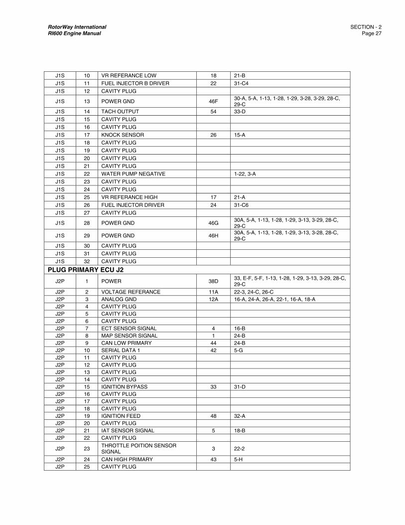
RotorWay International SECTION - 2 RI600 Engine Manual Page 27
J1S 10 VR REFERANCE LOW 18 21-B
J1S 11 FUEL INJECTOR B DRIVER 22 31-C4
J1S 12 CAVITY PLUG
J1S 13 POWER GND 46F 30-A, 5-A, 1-13, 1-28, 1-29, 3-28, 3-29, 28-C, 29-C
J1S 14 TACH OUTPUT 54 33-D
J1S 15 CAVITY PLUG
J1S 16 CAVITY PLUG
J1S 17 KNOCK SENSOR 26 15-A
J1S 18 CAVITY PLUG
J1S 19 CAVITY PLUG
J1S 20 CAVITY PLUG
J1S 21 CAVITY PLUG
J1S 22 WATER PUMP NEGATIVE 1-22, 3-A
J1S 23 CAVITY PLUG
J1S 24 CAVITY PLUG
J1S 25 VR REFERANCE HIGH 17 21-A
J1S 26 FUEL INJECTOR DRIVER 24 31-C6
J1S 27 CAVITY PLUG
J1S 28 POWER GND 46G 30A, 5-A, 1-13, 1-28, 1-29, 3-13, 3-29, 28-C, 29-C
J1S 29 POWER GND 46H 30A, 5-A, 1-13, 1-28, 1-29, 3-13, 3-28, 28-C, 29-C
J1S 30 CAVITY PLUG
J1S 31 CAVITY PLUG
J1S 32 CAVITY PLUG
PLUG PRIMARY ECU J2
J2P 1 POWER 38D 33, E-F, 5-F, 1-13, 1-28, 1-29, 3-13, 3-29, 28-C, 29-C
J2P 2 VOLTAGE REFERANCE 11A 22-3, 24-C, 26-C J2P 3 ANALOG GND 12A 16-A, 24-A, 26-A, 22-1, 16-A, 18-A J2P 4 CAVITY PLUG J2P 5 CAVITY PLUG J2P 6 CAVITY PLUG J2P 7 ECT SENSOR SIGNAL 4 16-B J2P 8 MAP SENSOR SIGNAL 1 24-B J2P 9 CAN LOW PRIMARY 44 24-B J2P 10 SERIAL DATA 1 42 5-G J2P 11 CAVITY PLUG J2P 12 CAVITY PLUG J2P 13 CAVITY PLUG J2P 14 CAVITY PLUG J2P 15 IGNITION BYPASS 33 31-D J2P 16 CAVITY PLUG J2P 17 CAVITY PLUG J2P 18 CAVITY PLUG J2P 19 IGNITION FEED 48 32-A J2P 20 CAVITY PLUG J2P 21 IAT SENSOR SIGNAL 5 18-B J2P 22 CAVITY PLUG
J2P 23 THROTTLE POITION SENSOR SIGNAL
3 22-2
J2P 24 CAN HIGH PRIMARY 43 5-H J2P 25 CAVITY PLUG
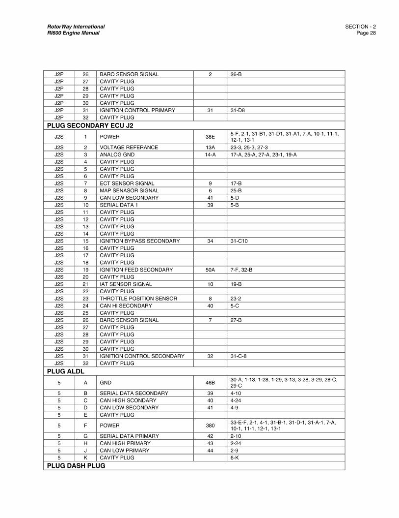
RotorWay International SECTION - 2 RI600 Engine Manual Page 28
J2P 26 BARO SENSOR SIGNAL 2 26-B J2P 27 CAVITY PLUG J2P 28 CAVITY PLUG J2P 29 CAVITY PLUG J2P 30 CAVITY PLUG J2P 31 IGNITION CONTROL PRIMARY 31 31-D8 J2P 32 CAVITY PLUG
PLUG SECONDARY ECU J2
J2S 1 POWER 38E 5-F, 2-1, 31-B1, 31-D1, 31-A1, 7-A, 10-1, 11-1, 12-1, 13-1
J2S 2 VOLTAGE REFERANCE 13A 23-3, 25-3, 27-3 J2S 3 ANALOG GND 14-A 17-A, 25-A, 27-A, 23-1, 19-A J2S 4 CAVITY PLUG J2S 5 CAVITY PLUG J2S 6 CAVITY PLUG J2S 7 ECT SENSOR SIGNAL 9 17-B J2S 8 MAP SENASOR SIGNAL 6 25-B J2S 9 CAN LOW SECONDARY 41 5-D J2S 10 SERIAL DATA 1 39 5-B J2S 11 CAVITY PLUG J2S 12 CAVITY PLUG J2S 13 CAVITY PLUG J2S 14 CAVITY PLUG J2S 15 IGNITION BYPASS SECONDARY 34 31-C10 J2S 16 CAVITY PLUG J2S 17 CAVITY PLUG J2S 18 CAVITY PLUG J2S 19 IGNITION FEED SECONDARY 50A 7-F, 32-B J2S 20 CAVITY PLUG J2S 21 IAT SENSOR SIGNAL 10 19-B J2S 22 CAVITY PLUG J2S 23 THROTTLE POSITION SENSOR 8 23-2 J2S 24 CAN HI SECONDARY 40 5-C J2S 25 CAVITY PLUG J2S 26 BARO SENSOR SIGNAL 7 27-B J2S 27 CAVITY PLUG J2S 28 CAVITY PLUG J2S 29 CAVITY PLUG J2S 30 CAVITY PLUG J2S 31 IGNITION CONTROL SECONDARY 32 31-C-8 J2S 32 CAVITY PLUG
PLUG ALDL
5 A GND 46B 30-A, 1-13, 1-28, 1-29, 3-13, 3-28, 3-29, 28-C, 29-C
5 B SERIAL DATA SECONDARY 39 4-10 5 C CAN HIGH SCONDARY 40 4-24 5 D CAN LOW SECONDARY 41 4-9 5 E CAVITY PLUG
5 F POWER 380 33-E-F, 2-1, 4-1, 31-B-1, 31-D-1, 31-A-1, 7-A, 10-1, 11-1, 12-1, 13-1
5 G SERIAL DATA PRIMARY 42 2-10 5 H CAN HIGH PRIMARY 43 2-24 5 J CAN LOW PRIMARY 44 2-9 5 K CAVITY PLUG 6-K
PLUG DASH PLUG
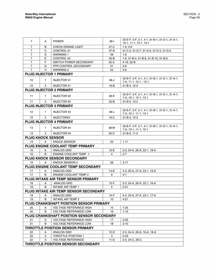
RotorWay International SECTION - 2 RI600 Engine Manual Page 29
7 A POWER 38-I 33-E-F, 5-F, 2-1, 4-1, 31-B-1, 31-D-1, 31-A-1, 10-1, 11-1, 12-1, 13-1
7 B CHECK ENGINE LIGHT 47-C 1-9, 3-9 7 C CONTROL #1 37-B 31-C-2, 31-D-7, 31-D-9, 31-D-3, 31-D-5 7 D WARNING 1 49 1-8 7 E CONTROL #2 35-B 1-6, 31-B-4, 31-B-8, 31-B-10, 31-B-6 7 F SWITCH POWER SECONDARY 50-C 4-19, 32-B 7 G FPR CONTROL SECONDARY 51 3-6 7 H WARNING 2 52 3-8
PLUG INJECTOR 1 PRIMARY
10 1 INJECTOR #1 38-J 33-E-F, 5-F, 2-1, 4-1, 31-B-1, 31-D-1, 31-A-1, 7-A, 11-1, 12-1 , 13-1
10 2 INJECTOR #1 19-B 31-B-3, 12-2
PLUG INJECTOR 2 PRIMARY
11 1 INJECTOR #2 38-K 33-E-F, 5-F, 2-1, 4-1, 31-B-1, 31-D-1, 31-A-1, 7-A, 10-1, 12-1, 13-1
11 2 INJECTOR #2 20-B 31-B-5, 13-2
PLUG INJECTOR 3 PRIMARY
12 1 INJECTOR #3 38-L 33-E-F, 5-F, 2-1, 4-1, 31-B-1, 31-D-1, 31-A-1, 7-A, 10-1, 11-1, 13-1
12 2 INJECTOR#3 19-C 31-B-3, 10-2
PLUG INJECTOR 4 PRIMARY
13 1 INJECTOR #4 38-M 33-E-F, 5-F, 2-1, 4-1, 31-B-1, 31-D-1, 31-A-1, 7-A, 10-1, 11-1, 12-1
13 2 INJECTOR #4 20-C 31-B-5, 11-2
PLUG KNOCK SENSOR 14 A KNOCK SENSOR 25 1-17
PLUG ENGINE COOLANT TEMP PRIMARY 16 A ANALOG GND 12-E 2-3, 24-A, 26-A, 22-1, 18-A 16 B ENGINE COOLANT TEMP 1 4 2-7
PLUG KNOCK SENSOR SECONDARY 15 A KNOCK SENSOR 2 26 3-17
PLUG ENGINE COOLANT TEMP SECONDARY 17 A ANALOG GND 14-E 4-3, 25-A, 27-A, 23-1, 19-A 17 B ENGINE COOLANT TEMP 2 9 4-7
PLUG INTAKE AIR TEMP SENSOR PRIMARY 18 A ANALOG GRD 12-F 2-3, 24-A, 26-A, 22-1, 16-A 18 B INTAKE AIR TEMP 1 5 2-21
PLUG INTAKE AIR TEMP SENSOR SECONDARY 19 A ANALOG GND 14-F 4-3, 25-A, 27-A, 23-1, 17-A 19 B INTAKE AIR TEMP 2 10 4-21
PLUG CRANKSHAFT POSITION SENSOR PRIMARY 20 A VOLTAGE REFERANCE HIGH 15 1-25 20 B VOLTAGE REFERANCE LOW 16 1-10
PLUG CRANKSHAFT POSITION SENSOR SECONDARY 21 A VOLTAGE REFERANCE HIGH 17 3-25 21 B VOLTAGE REFERANCE LOW 18 3-10
THROTTLE POSITION SENSOR PRIMARY 22 A ANALOG GND 12-D 2-3, 24-A, 26-A, 16-A, 18-A 22 2 THROTTLE POSITION 1 3 2-23 22 3 VOLTAGE REFERANCE 11-D 2-2, 24-C, 26-C
THROTTLE POSITION SENSOR SECONDARY
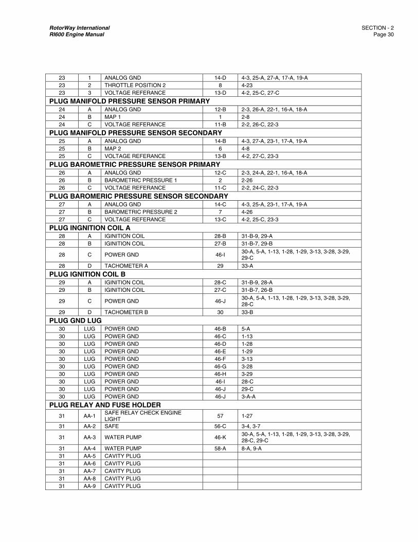
RotorWay International SECTION - 2 RI600 Engine Manual Page 30
23 1 ANALOG GND 14-D 4-3, 25-A, 27-A, 17-A, 19-A 23 2 THROTTLE POSITION 2 8 4-23 23 3 VOLTAGE REFERANCE 13-D 4-2, 25-C, 27-C
PLUG MANIFOLD PRESSURE SENSOR PRIMARY 24 A ANALOG GND 12-B 2-3, 26-A, 22-1, 16-A, 18-A 24 B MAP 1 1 2-8 24 C VOLTAGE REFERANCE 11-B 2-2, 26-C, 22-3
PLUG MANIFOLD PRESSURE SENSOR SECONDARY 25 A ANALOG GND 14-B 4-3, 27-A, 23-1, 17-A, 19-A 25 B MAP 2 6 4-8 25 C VOLTAGE REFERANCE 13-B 4-2, 27-C, 23-3
PLUG BAROMETRIC PRESSURE SENSOR PRIMARY 26 A ANALOG GND 12-C 2-3, 24-A, 22-1, 16-A, 18-A 26 B BAROMETRIC PRESSURE 1 2 2-26 26 C VOLTAGE REFERANCE 11-C 2-2, 24-C, 22-3
PLUG BAROMERIC PRESSURE SENSOR SECONDARY 27 A ANALOG GND 14-C 4-3, 25-A, 23-1, 17-A, 19-A 27 B BAROMETRIC PRESSURE 2 7 4-26 27 C VOLTAGE REFERANCE 13-C 4-2, 25-C, 23-3
PLUG INGNITION COIL A 28 A IGINITION COIL 28-B 31-B-9, 29-A 28 B IGINITION COIL 27-B 31-B-7, 29-B
28 C POWER GND 46-I 30-A, 5-A, 1-13, 1-28, 1-29, 3-13, 3-28, 3-29, 29-C
28 D TACHOMETER A 29 33-A
PLUG IGNITION COIL B 29 A IGINITION COIL 28-C 31-B-9, 28-A 29 B IGINITION COIL 27-C 31-B-7, 26-B
29 C POWER GND 46-J 30-A, 5-A, 1-13, 1-28, 1-29, 3-13, 3-28, 3-29, 28-C
29 D TACHOMETER B 30 33-B
PLUG GND LUG 30 LUG POWER GND 46-B 5-A 30 LUG POWER GND 46-C 1-13 30 LUG POWER GND 46-D 1-28 30 LUG POWER GND 46-E 1-29 30 LUG POWER GND 46-F 3-13 30 LUG POWER GND 46-G 3-28 30 LUG POWER GND 46-H 3-29 30 LUG POWER GND 46-I 28-C 30 LUG POWER GND 46-J 29-C 30 LUG POWER GND 46-J 3-A-A
PLUG RELAY AND FUSE HOLDER
31 AA-1 SAFE RELAY CHECK ENGINE LIGHT
57 1-27
31 AA-2 SAFE 56-C 3-4, 3-7
31 AA-3 WATER PUMP 46-K 30-A, 5-A, 1-13, 1-28, 1-29, 3-13, 3-28, 3-29, 28-C, 29-C
31 AA-4 WATER PUMP 58-A 8-A, 9-A 31 AA-5 CAVITY PLUG 31 AA-6 CAVITY PLUG 31 AA-7 CAVITY PLUG 31 AA-8 CAVITY PLUG 31 AA-9 CAVITY PLUG

RotorWay International SECTION - 2 RI600 Engine Manual Page 31
31 AA-1 CAVITY PLUG
31 A-1 POWER 38-H 33-E-F, 5-F, 2-1, 4-1, 31-B-1, 31-D-1, 7-A, 10-1, 11-1, 12-1, 13-1
31 A-2 SAFE 36 31-B-2 31 A-3 WATER PUMP 1-22, 3-22 31 A-4 WATER PUMP 8-B 31 A-5 CAVITY PLUG 31 A-6 CAVITY PLUG 31 A-7 CAVITY PLUG 31 A-8 CAVITY PLUG 31 A-9 CAVITY PLUG 31 A-10 CAVITY PLUG
31 B-1 POWER 38-F 33-E-F, 5-F, 2-1, 4-1, 31-D-1, 31-A-1, 7-A, 10-1, 11-1, 12-1, 13-1
31 B-2 CONTROL #3 36 31-A-2 31 B-3 INJECTOR DRIVER B 19-A 10-2, 12-2 31 B-4 CONTROL #2 35-C 7-E, 1-6, 31-B-8, 31-B-10, 31-B-6 31 B-5 INJECTOR DRIVER A 20-A 11-2, 13-2 31 B-6 CONTROL #2 35-F 7-E, 1-6, 31-B-4, 31-B-8, 31-B-10 31 B-7 27-A 28-B, 29-B 31 B-8 CONTROL #2 35-D 7-E, 1-6, 31-B-4, 31-B-10, 31-B-6 31 B-9 38-A 28-A, 29-A 31 B-10 CONTROL #2 35-E 7-E, 1-6, 31-B-4, 31-B-8, 31-B-6 31 C-1 CAVITY PLUG 31 C-2 CONTROL #1 37-A 7-C, 31-D-7, 31-D-9, 31-D-3, 31-D-5 31 C-3 CAVITY PLUG 31 C-4 FUEL INJECTOR B DRIVER 22 3-11 31 C-5 CAVITY PLUG 31 C-6 FUEL INJECTOR A DRIVER 24 3-26 31 C-7 CAVITY PLUG 31 C-8 INGITION CONTROL SECONDARY 32 4-31 31 C-9 CAVITY PLUG 31 C-10 IGNITION BYPASS 34 4-15
31 D-1 POWER 38-G 33-E-F, 5-F, 2-1, 4-1, 31-B-1, 31-A-1, 7-A, 10-1, 11-1, 12-1, 13-1
31 D-2 CAVITY PLUG 31 D-3 CONTROL #1 37-E 7-C, 31-C-2, 31-D-7, 31-D-9, 31-D-5 31 D-4 FUEL INJECTOR B DRIVER 21 1-11 31 D-5 CONTROL #1 37-F 7-C, 31-C-2, 31-D-7, 31-D-9, 31-D-3 31 D-6 FUEL INJECTOR A DRIVER 23 1-26 31 D-7 CONTROL #1 37-C 7-C, 31-C-2, 31-D-9, 31-D-3, 31-D-5 31 D-8 IGNITION CONTROL A 31 2-31 31 D-9 CONTROL #1 37-D 7-C, 31-C-2, 31-D-7, 31-D-3, 31-D-5 31 D-10 IGNITION BYPASS 33 2-15
PLUG IGNITION SWITCH 32 A SWITCH POWER PRIMARY 48 2-19 32 B SWITCH POWER SECONDARY 50-B 7-F, 4-19
PLUG COILS POWER AND TACHOMETER 33 A IGNITION A SWITCH POWER 29 28-D 33 B IGNITION B SWITCH POWER 30 29-D 33 C TACHOMETER 1 53 1-14 33 D TACHOMETER 2 54 3-14
33 E POWER 38-A 33-F, 5-F, 2-1, 4-1, 31-B-1, 31-D-1, 31-A-1, 7-A, 10-1, 11-1, 12-1, 13-1

RotorWay International SECTION - 2 RI600 Engine Manual Page 32
33 F POWER 38-B 33-E, 5-F, 2-1, 4-1, 31-B-1, 31-D-1, 31-A-1, 7-A, 10-1, 11-1, 12-1, 13-1
C. Cooling System
1. Coolant Requirements
Propylene Glycol is the recommended choice for coolant/anti-freeze. Propylene Glycol offers improved cavitation corrosion protection, lower toxicity, and better overall performance than Ethylene Glycol. We strongly recommend that you DO NOT use Ethylene Glycol coolant/anti-freeze. It is also necessary to include a compatible supplemental coolant additive (Fleetgaurd additive DCA 60L). WIX #24056 and NALCOOL #3000 are two of the quality additives available. The best source for locating other brands is diesel parts stores because cylinder corrosion is common in diesel engines. Follow directions for the correct concentration of additive as more is not better. We have tested a Propylene Glycol anti-freeze solution called COMPLEAT, which contains the proper concentrations of propylene glycol and corrosion inhibitor additive. The best type is their “PREMIXED” version, which already has the proper amount of distilled water added. This product is distributed by FLEETGARD Inc., a Cummins (diesel) company. CAUTION: NEVER USE WATER ONLY IN THE COOLING SYSTEM. Never mix tap water or well water with the
antifreeze concentrate. Use ONLY DISTILLED WATER to mix with the antifreeze solution. RotorWay recommends that you have the coolant/anti-freeze solution tested once every year. Fleetgaurd coolant test strips (CC2602A) for measuring freezing point, molybdate and nitrite. Normally, the coolant should be left in the system until the recommended change out time of the hoses (refer to the Maintenance Manual). At that time replace the hoses, hose clamps, and coolant. Preparation Review the Prints and Manuals to ensure that all cooling system components are attached and routed correctly. Verify that all hoses are secure and that hose clamps are installed past the bead or flare on the end of the adjoining tube or fitting. All hoses must be protected from the heat of the exhaust manifolds. The tie down and routing of all hoses must be done in such a way as to prevent chafing damage. Prepare the propylene glycol coolant solution according to the directions given by the manufacturer. Cooling system capacity is approximately 10 US quarts (9.5 liters). Ensure that enough solution has been prepared so that the surge tank can be kept 3/4 full at all times. Open all three air bleed valves slightly. The valves are located on the rear corner of the radiator, the 120° inlet manifold near the water pump, and the plug in the elbow on top of the waterjacket. All are on the passenger side of the helicopter. Use clear plastic hose on the bleed valves and use a catch container to recover as much coolant mixture as possible. Remove the radiator cap from the surge tank. Locate the test/bleed jumper supplied with the water pump. This will be used in the next step to connect the pump to the battery, so that the pump can operate without starting the engine.
RotorWay International SECTION - 2 RI600 Engine Manual Page 33
2. Preparation
A. Review the Prints and Manuals to ensure that all cooling system components are attached and routed correctly. Verify that all hoses are secure and that hose clamps are installed past the bead or flare on the end of the adjoining tube or fitting. All hoses must be protected from the heat of the exhaust manifolds. The tie down and routing of all hoses must be done in such a way as to prevent chafing damage.
B. Prepare the propylene glycol coolant solution according to the directions given by the manufacturer. Cooling system
capacity is approximately 10 US quarts (9.5 liters). Ensure that enough solution has been prepared so that the surge tank can be kept 3/4 full at all times.
C. Open all three air bleed valves slightly. The valves are located on the rear corner of the radiator, the 120° inlet
manifold near the water pump, and the plug in the elbow on top of the waterjacket. All are on the passenger side of the helicopter. Use clear plastic hose on the bleed valves and use a catch container to recover as much coolant mixture as possible.
D. Remove the radiator cap from the surge tank.
E. Locate the test/bleed jumper supplied with the water pump. This will be used in the next step to connect the pump to
the battery, so that the pump can operate without starting the engine.
3. Filling the System, Removing Air and Priming the Water Pump
CAUTION: Removing air from the cooling system and priming the water pump is VERY IMPORTANT to avoid damage to the engine.
CAUTION: The water pump should not be allowed to operate without coolant in the hoses and pump.
NOTE: The waterpump is controlled by the engine ECUs. The pump does not run while the engine is off. The
engine water temp sensors (primary and secondary) give the ECUs input for control.
A. Slowly pour the coolant mixture into the surge tank until it flows continuously from the air bleed valves. When a steady stream of coolant without air bubbles is emitted, close the valves. Fill until the surge tank is 3/4 full. The tank must be continuously filled to maintain this level throughout the entire procedure.
B. Check all hoses for any sign of leakage and correct as necessary.
C. Connect the bottom of the surge tank overflow hose to the bleed valve on the radiator. If it leaks, secure it with a hose
clamp.
D. Open the bleed valve on the radiator. Coolant should rise up the hose to the level of the coolant in the surge tank. Re-fill the tank as needed, then close the bleed valve.
E. Unplug the water pump from the wiring harness, and using the test/bleed jumper, connect the water pump to a 12 volt
battery. Slowly open the valve on the radiator again. You should see coolant flow through the hose into the surge tank; if not, re-bleed by opening the valve on the 120 degree inlet manifold.
NOTE: To reduce splashing, install the cap loosely on the surge tank or cover the opening with a folded rag.
RotorWay International SECTION - 2 RI600 Engine Manual Page 34
F. Any air remaining in the system can be heard as gurgling. While the pump is running, the bleed valves on the inlet manifold and on the engine should be opened occasionally to allow air to escape. Rocking the aircraft on the ground handling wheels can help move air pockets to the bleed valve areas. Continue running the pump until all air is removed from the system, approximately 10 to 30 minutes.
G. When finished, remove clear hoses from the bleed valves and return the surge tank overflow hose to it’s original
position. Make sure all bleed valves are securely closed. Install and tighten the radiator cap.
D. Oil System
1. Preparation and Priming
Prior to the first engine start-up, the oil pump MUST BE PRIMED. The RI 600 power plant uses a G-Rotor pump rather than a gear type unit. The G-Rotor has several design advantages over the gear type. It does have the disadvantage of needing a prime before first operation. The oil fittings have been angled up at the inlet and outlet side of the oil pump. This is done intentionally in order to keep enough oil at the pump to maintain a prime after shutdown of the engine. The pump should not have to be re-primed again even after a prolonged interval of no engine operation. CAREFULLY follow the sequence outlined below before the initial starting of the engine. A. Before installing the oil sump/heat exchanger or any oil hoses, they must all be thoroughly cleaned. Carefully flush them
with solvent, completely drain and blow them dry. NOTE: After cleaning the sump, lubricate the inside of the filler neck with oil to prevent the cap from galling the aluminum
filler neck tube. B. Before connecting any oil hoses to the engine, fill the oil pump inlet and outlet fittings with oil. These fittings are numbers 2
and 3 in the Oil System Parts List. These fittings will have to be refilled repeatedly until all of the trapped air has been bled out and they remain completely full.
C. Install all oil hoses. The fittings on the ends of the hoses are aluminum and can be permanently damaged if over
tightened. Secure all hoses away from hot exhaust pipes. Secure hoses in such a way as to avoid any contact with ANY other component of the aircraft.
D. Before screwing on the oil filter, coat the rubber gasket with a light film of oil. Fill the oil filter with oil. It holds approximately
1/2 quart. Add the oil slowly, allowing it to soak in. Screw the filter onto the mount by hand. Tighten it firmly by hand only. Approximately 2/3 of a turn after initial contact is correct. Do NOT use a wrench to tighten the filter to the mount as this will make it nearly impossible to remove for replacement.
E. Pour the remaining 1/2 quart of oil into the oil sump/heat exchanger. Scribe two lines on the dipstick which is attached to
the breather cap. These lines should represent levels below the top of the filler neck of 8-3/4" and 9-1/4". The oil level must be maintained between these lines at all times. You will be instructed to “top off” the oil level after stopping the engine the first time.
NOTE: If the oil level in the sump is too low, ineffective oil cooling will result. If the oil level is too high, oil will blow out of the
filler pipe. F. The oil system is now ready for the first engine start-up. All other systems must be prepared before starting the engine.
When the engine is started for the first time do NOT operate above a low idle until oil pressure is obtained.
RotorWay International SECTION - 2 RI600 Engine Manual Page 35
CAUTION: If proper oil pressure is NOT obtained after 5 seconds of running, STOP the engine and re-prime the pump as explained in step C above. Adjust the oil pressure if necessary (see Oil Pressure Adjustment section below).
G. When correct oil pressure is observed, continue to run the engine until an oil temperature of 140° F is obtained and then
STOP the engine. WARNING: After the initial start-up and during the first run of the helicopter, carefully monitor the entire oil system for
leaks. Oil can catch on fire, especially if it leaks onto the exhaust system. H. After the engine is stopped, allow time for the oil to completely drain back into the oil sump/heat exchanger. Add oil to
bring the level between the marks on the dipstick. NOTE: At this time the re-bleeding of the cooling system should be done. CAUTION: Check the oil level in the sump during each pre-flight inspection of the helicopter. Add oil if necessary to
bring the oil level up to the scribe mark on the dipstick. Always check the oil pressure on each start-up and throughout each flight. Continually monitor the ENTIRE oil system for any leakage and regularly check all hoses for ANY sign of damage.
2. Oil Pressure Adjustment
A. Oil pressure adjustments must be made when the engine is at operating temperature. (See specification section for exact operating parameters.) The only time oil pressure would need to be adjusted when the engine is cold would be if the oil pressure did not meet the minimum or maximum specifications on initial start-up. Oil pressure MUST fall within the stated parameters at idle and at full RPM.
The oil pressure was set at the factory during the dynamometer testing of the engine. A slight adjustment may have to be made in order to “tune” the pressure regulator to your ship’s particular oil system. This adjustment should be minor and should not have to be made during the initial warm up of your engine. However, do not take this for granted. Carefully monitor your oil pressure at all times.
B. To adjust the oil pressure, first look at the exploded view of the oil pump cover and the pressure regulator
components, found in the Lower Cover Assembly drawing in Section 5 of this manual. Take the time to become familiar with the component parts. It is recommended that you make any adjustment to the oil pressure only when the engine is stopped. As you will notice, the adjustment requires that your hands come in close proximity to the hot exhaust system. This, in conjunction with the generally close quarters, warrants special care from a safety point of view.
C. Proceed as follows to make an adjustment of the oil pressure: Loosen the jam nut on the socket head cap screw. (Be
careful not to move the cap screw when loosening the nut.) Turning the cap screw clockwise will increase the oil pressure and turning counter clockwise will lower the pressure. It is suggested that you turn the cap screw in increments of 1/4 turn at a time until the desired pressure is achieved. Each time an adjustment is made, re-torque the jam nut to 108 in. lbs. After any adjustment, completely clean off any trace of oil and check for any leaks. If an oil leak is found around the socket head cap screw where it enters the regulator plug, the O-ring must be replaced. To do this, remove the cap screw while carefully counting the exact number of turns as it comes out. Be prepared for a small stream of oil to come out of the regulator plug. When you reinstall the screw, turn it in exactly the same number of turns. By doing this you should be close to the previous setting. During any adjustment, pay close attention to the oil pressure. MAKE SURE you are not running the engine with incorrect oil pressure.

RotorWay International SECTION - 2 RI600 Engine Manual Page 36
I. Ignition System
1. Introduction
The dual ignition system utilized on the RI 600 engine is extremely reliable and easy to maintain. It should provide many hours of trouble free performance. Many types of ignition systems were analyzed and evaluated before deciding to use this system. The system consists of two complete and separate ignition units. Each unit fires one set of spark plugs. Unlike other ignition systems, they do not use a rotor and cap; they fire the spark plugs directly from the coils. The spark control is completely electronic. An additional feature allows the primary ECU (when activated) to override the programmed advance curve of the ignition modules. The ECU then controls ignition timing based on the specific performance requirements of the powerplant. With this type of ignition system, a spark occurs every time a piston approaches its top position. A spark occurs on the compression stroke and at the end of the exhaust stroke. This “extra” spark on the exhaust stroke has no effect on the running engine since there is no mixture present to ignite. (An excess of fuel in the intake manifolds or cylinders can cause a pop or backfire on start-up.) Each ignition system contains five components: ignition module, sensor, timing wheel, spark plugs, and spark plug wires. The only shared component between the two systems is the timing wheel which is mounted on the drive flange of the crankshaft. Each sensor transmits a signal to its own ignition module every time a tooth segment passes that sensor. The ignition module then identifies the relative position of the crankshaft and delivers a spark to the plugs based on the timing required for that RPM. The entire function of spark advance from starting to full RPM operation is controlled and requires no adjustment. The maintenance is very simple on this system. Spark plugs and spark plug wires are replaced at proper intervals. A sensor or ignition module is replaced if either is found to be defective in pre or post flight checks. This should be the most trouble free and effective ignition system you could wish for in any aircraft. NOTE: There are certain operational parameters that must not be violated. These will be covered in detail in this section of
the manual. You must carefully read this material prior to installation of the units. Failure to do so could result in permanent damage to the ignition modules.
2. Preparation
WARNING: NEVER ELECTRIC WELD with either the ignition modules or the ECUs connected in ANY way to the electrical system of the ship. This means that the positive, negative, ground strap, and sensor connections must be disconnected before any welding is preformed!
DO NOT PROVIDE CURRENT to the ignition units until all of the following procedures have been done and double checked. The following installation and operating procedures MUST be followed before the initial start-up of the engine. Failure to understand and follow these procedures will result in damage to the ignition systems.
A. Use the installation drawing to verify that the FADEC wiring harness has been correctly installed on the ignition modules. The “end” connectors on the harness should plug into the inboard module.
B. The separate grounding strap MUST be installed to the mounting plate. This effectively grounds the body of each
unit. This is required in addition to the wiring harness ground connection of each unit.
C. Connect the FADEC harness wires to the ignition modules: Use the ignition installation drawing to ensure that the correct sensor attaches to the proper module. The sensor wires need to be carefully secured to prevent damage. They also MUST be routed so that they do not come into close proximity with ANY other wires. The signal transmitted
RotorWay International SECTION - 2 RI600 Engine Manual Page 37
by these wires is very weak and interference from other wires close by could cause false signals to be sent to the ignition modules. Pay close attention to the routing of these wires in relation to the spark plug wires as they are proven the most likely source of interference. The FADEC wiring harness which is connected to the ignition modules must not be allowed to contact the spark plug wires.
D. Install the spark plugs: Be sure to gap, torque and install the end caps according to specifications. (Always inspect
the spark plug threads for damage and apply a light film of anti-seize before installation.)
E. Install the spark plug wires: Use the ignition installation drawing as a guide to the proper connection of these wires. Be sure to double check the connections you have made. (Incorrect spark plug wire hookup is surprisingly easy to do.) Before attaching each wire, look inside the boot and verify that the metal end is in the proper position. When the wire is installed on either a coil tower or a spark plug it should snap into place and feel solidly attached. Wire separators have been provided to properly route the wires. Route the wires in such a way that all of the following conditions are met:
1. No two wires can come in direct contact with each other. 2. Wiring must be very well supported and not allowed to chafe or vibrate excessively. 3. No wire can be pulled tight. Some torque movement of the engine will occur and the wires must have
enough slack to move with the engine. WARNING: NEVER CRANK, START, OR RUN THE ENGINE WITH ANY OF THE SPARK PLUG WIRES
DISCONNECTED FROM EITHER THE IGNITION MODULES OR THE PLUGS! NOTE: Use dialectric grease on the spark plug boots at the coil side. The boots fit very tight, the grease will help with
installation.
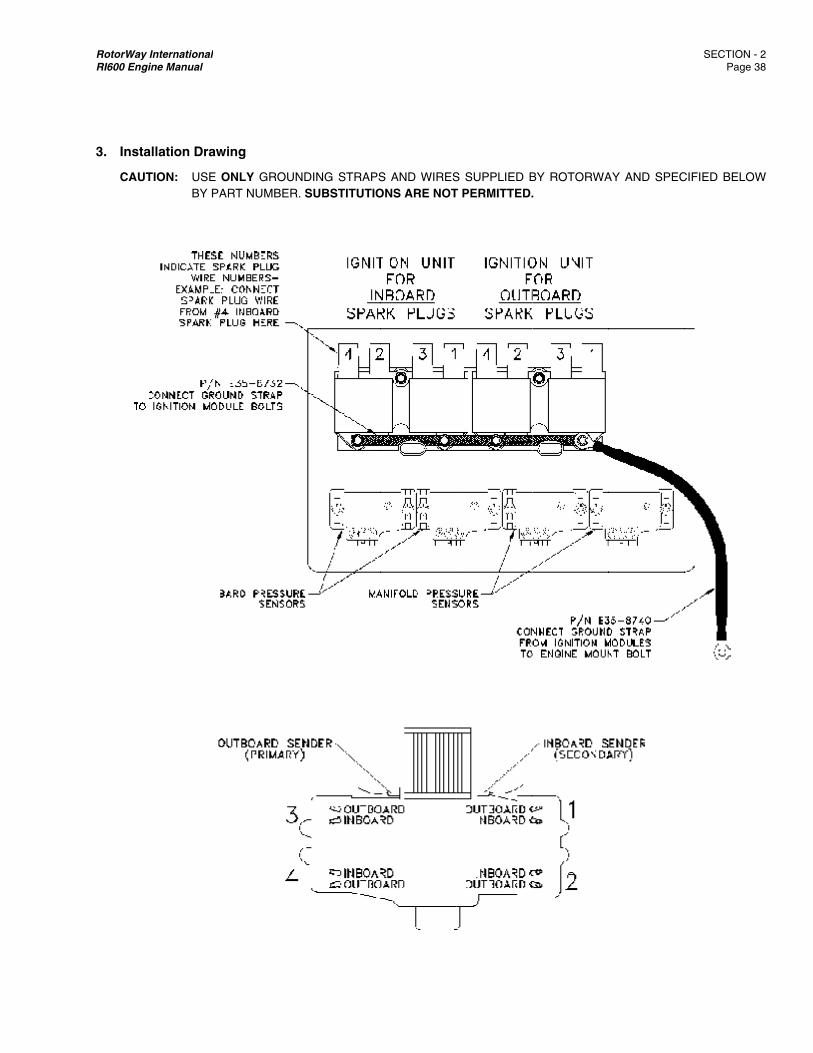
RotorWay IRI600 Engin
3. Instal
CAUT
International ne Manual
llation Drawi
TION: USE OBY PAR
ing
ONLY GROUNRT NUMBER.
DING STRAPSSUBSTITUTIO
S AND WIRESONS ARE NOT
S SUPPLIED BT PERMITTED.
BY ROTORWA.
AY AND SPEC
SECTION - 2 Page 3
CIFIED BELOW
2 8
W
RotorWay International SECTION - 2 RI600 Engine Manual Page 39
4. Component Service
a) Ignition Sensors The inboard and outboard ignition sensors are identical. TESTING: Disconnect the sensor at the plug connector by lifting the lock tab and pulling the connector apart. Pull on the connector body only, not on the wires themselves. The resistance between terminals A and B, of the sensor, should be 600 to 800 ohms. REMOVAL: Disconnect the sensor at the plug connector by lifting the lock tab and pulling the connector apart. Pull on the connector body only. Remove screw and guide plate, screw was installed with service removable locktite 241, blue. If it does not come out easily, carefully grab it with a pair of pliers and rotate it back and forth while attempting to pull it out. If the sensor is to be used again, be careful not to damage it. Do not squeeze it too hard or damage from crushing may occur. INSTALLATION: Deburr the sensor hole in the starter mount if necessary. The sensor must be able to slide in and out of the hole easily. Care should be taken to avoid elongating or enlarging the hole. Use compressed air to THOROUGHLY blow clean the area inside the starter mount which encloses the ignition timing wheel. (Chips could wedge between the wheel and sensor causing damage to the sensor.) Rotate the engine (using a flywheel wrench) until a tooth of the timing wheel is exactly centered on the sensor hole. This position will be correct by lining up “S” line on flywheel with yellow indicator mark on starter mount. A small mirror and flashlight will be needed to verify the proper positioning of the tooth. Apply a LIGHT film of anti-seize to the outside diameter of the sensor. The end of the sensor which is toward the timing wheel MUST remain clean and free of lubricant. Excess anti-seize will only contaminate the sensor and act as a trap for dirt and chips. Carefully insert the replacement sensor in the hole. Install guide plate and snug screw down. The feeler gauge should be able to be moved back and forth between the sensor and the tooth with a light drag. If the feeler gauge does not move easily, DO NOT force it. Check gap 0.015”/0.025” check two other teeth which are located 120 degrees on either side of the tooth used to set the gap. Do not leave the feeler gauge in place while rotating the flywheel as slight variations in gap could damage the sensor. (Be careful if you rotate the flywheel clockwise as this will cause the blades to turn.) Using wire ties, secure the sensor wire in such a way as to keep it from vibrating or being damaged by the heat from the exhaust. Reconnect the sensor wire plug and make sure that the locking tab engages.
b) Ignition Modules Inboard and outboard ignition Modules are identical and interchangeable components. Testing is covered in the following Diagnostic Section. REPLACEMENT: It is important that the mounting holes in both the seat back panel and in the module backing plate are large enough for the mounting bolts to be tightened without any binding. The ignition modules must sit flat against the backing plate and not bind or twist during the bolt tightening process. The mounting bolts must be gradually tightened until snug. They must then be torqued to 75 in. lbs. The ground wires must be properly installed in order to provide an adequate “ground source” for the ignition modules.
c) Spark Plug Wires Spark plug wires should be replaced only with ones supplied by the factory. The use of incorrect spark plug wires can cause permanent DAMAGE to the ignition modules! The spark plug wire supplied by the factory is spherically wound and has a resistance which is less than 700 ohms per foot. It is a special grade of wire and has passed the testing required for its use.

RotorWay International SECTION - 2 RI600 Engine Manual Page 40
DO NOT use any wire because you believe it to be similar to the factory supplied type! A damaged spark plug wire will test as a “short” or have a high resistance value.
d) Spark Plugs Use only direct replacement plugs. Do not change heat range and do not change to a non-resistor type plug. Damage to the ignition modules and to the engine can result from the use of incorrect spark plugs. Every 50 hours inspect and re-gap all spark plugs. Replace a plug at the first sign of damage or fouling. Mandatory replacement is 100 hours. NOTE: Change spark plugs only when the engine is cold! Inspect each plug carefully before installation. Pay close attention to any possible damage of the threads. Always screw a spark plug in by hand only and then torque it. If a plug has to be turned in with a socket, damage to the threads in the cylinder head will probably occur. Always pre-coat the threads of the spark plugs with a LIGHT film of anti-seize before installation. Secure the end cap onto the plug.
5. Diagnostics
NOTE: The ignition modules cannot compute the proper spark timing sequence if the engine is cranking too slowly. Because of this, the ENGINE WILL NOT START! The modules can also be damaged by continuous operation at a low or a high voltage. For these reasons, ensure that the battery has a good charge before attempting to start the engine and verify that the alternator is working properly after start-up by monitoring the voltmeter.
Pre- and post-flight ignition checks are done by alternately turning off and on each system individually. The RPM may drop slightly but should not stop the engine or cause it to misfire dramatically. WARNING: DO NOT perform the ignition checks above an idle, as a faulty system could stop the engine or possibly
cause severe backfiring. These diagnostic procedures are very simple and straight forward. They must be followed in sequence. Failure to do so can result in much wasted time and the possible purchase of unneeded and expensive parts! All of these procedures assume that the ignition system is installed properly. If you have a problem on the initial start-up, recheck your installation before following the diagnostic procedures. Below are listed a series of possible problems which may be encountered. If you have a problem with the ignition system, find the heading which fits the problem and follow the accompanying procedure until a problem is found AND CORRECTED. If after correcting a problem the ignition system still does not perform properly, then and only then go on to the next procedure.
a) Engine Will Not Start - Signs of combustion are evident, (such as backfire or sputter)
1. If the battery is properly charged and the cranking speed is good, the engine is probably flooded. Turn off all FADEC switches and turn on both ignitions. Hold the throttle wide open (100% indicated) and crank the engine until no sign of combustion is evident. (No fuel is delivered to the engine below 1000 RPM at a wide open throttle setting.) If necessary, remove the spark plugs and check for signs of fouling. A common cause of backfire or sputter on start-up is fuel fouling of the spark plugs.
2. Check for power at both ignition modules using a voltmeter.
3. Try starting the engine on the inboard system only. Repeat on the outboard system only. If the engine starts and
runs on either system and starts to miss or if it quits when the other system is turned on, see “Engine Runs On One System Only”.

RotorWay International SECTION - 2 RI600 Engine Manual Page 41
4. If the engine will not start on either system, check the sensor gap on both the outboard and the inboard systems.
5. Install a timing light on #1 outboard spark plug wire. With only the outboard system turned on, crank the engine
to check for spark. Do the same to outboard wires #2, #3 and #4. If a spark is present on all 4 plugs and none of the plugs were fouled, then there is probably not enough fuel present for start-up.
NOTE: Crank the engine only long enough to verify spark. DO NOT crank the engine for a prolonged period as this could
damage the starter and the engine.
Pre-check the timing light for proper operation. If its operation is questionable, an alternate method may be used to verify spark at the plug: Remove the spark plug wire from the cylinder in question. Remove the spark plug and reattach the spark plug wire to it. Install an extra spark plug in the vacant hole. Attach a grounded strap to the base of the removed spark plug. Hold this grounded plug against a grounded surface which is not near any fuel source! Care must be taken to avoid shock AND to prevent the system from being run with a plug wire disconnected. For this reason, do not eliminate the grounding strap from this procedure.
6. If no spark is evident at ANY cylinder and if the voltage AND cranking speed are good, either a sensor or an
ignition module is probably bad. In this case, skip 7-9 and proceed to 10. If any of the plugs show signs of spark proceed to 7.
7. If only one, two, or three of the spark plugs do not show signs of spark, then replace the questionable spark
plugs and retest. (Defective spark plugs can cause this type of problem.)
8. If only one, two, or three of the spark plugs still show no evidence of a spark, remove the questionable spark plug wires from the defective cylinders. Check for continuity with an ohm meter. If a defective wire is found, retest that cylinder after replacing the wire.
9. If this is also not the problem, then either the sensor or the ignition module is defective. 10. Repeat procedures (1 through 9) on the inboard set of spark plugs.
11. A situation where both systems were defective would be very unlikely since a sensor or an ignition module would
have to be defective on each system. Call customer service before proceeding further!
b) ENGINE WILL NOT START - Signs of spark are evident, (such as backfire or sputter)
1. Check for power at both modules using a voltmeter.
2. If the battery is properly charged and the cranking speed is good, the engine may be severely flooded. Turn off all FADEC switches and turn on both ignitions. Hold the throttle wide open (100% indicated) and crank the engine until no sign of combustion is evident. (No fuel is delivered to the engine below 1000 RPM at a wide open throttle setting.) If necessary, remove the spark plugs and check for signs of fouling.
Insufficient fuel can also keep the engine from firing, so check for an apparent total lack of fuel!
3. Check sensor gap on both inboard and outboard units.
RotorWay International SECTION - 2 RI600 Engine Manual Page 42
4. Install a timing light on #1 outboard wire. With only the outboard system on, crank the engine to check for spark. Repeat as necessary on the remaining wires to determine if a spark is being produced. (Do not crank engine for a prolonged period as this could damage the starter and the engine.)
If a good spark is present on all plugs and the plugs were not fouled, there is probably not enough fuel present for start-up.
5. If no spark is evident at ANY spark plug and if the voltage AND cranking speeds are good, either a sensor or an
ignition module is probably bad. In this case, skip 6-8 and proceed to 9. If any of the plugs show signs of spark, proceed to 6.
6. If only one, two, or three of the spark plugs do not show signs of spark, then replace the questionable spark plugs
and retest. (Defective spark plugs can cause this type of problem.)
7. If only one, two, or three of the spark plugs still show no evidence of a spark, remove the questionable spark plug wires from the defective cylinders. Check for continuity with an ohm meter. If a defective wire is found, retest that cylinder after replacing the wire.
8. If this is also not the problem, then either the sensor or the ignition module is defective.
9. Repeat this process on the inboard set of spark plugs.
10. A situation where both systems were defective would be very unlikely since a sensor or an ignition module would
have to be defective on each systems. Call customer service before proceeding further!
c) ENGINE RUNS ON ONE SYSTEM ONLY.
1. Identify whether the inboard or outboard system is defective. Check for power to the defective system using a voltmeter.
2. Install a timing light on a wire of the operable system to verify proper operation of the light. (Run the engine at an idle
only.) Check to determine if any of the spark plugs of the defective unit are firing. Do this by checking each of them with the timing light at idle. IF NONE of the spark plugs show any sign of spark, proceed to 3. If some of the cylinders are firing, check the spark plugs in the defective cylinders for signs of fouling and check the corresponding spark plug wires for damage.
3. Test the ignition sensor using an ohm meter and check the sensor gap on the defective system. These checks should be a good indication of the sensor’s condition. Ignition sensors can fail hot or cold. If an intermittent problem exists test sensors both hot and cold. To verify whether the ignition sensor or the ignition module is defective, proceed to 4.
4. Warm up the engine and verify good restart ability. Switch connector plugs between the modules. (Referring to the FADEC Wiring Harness, switch Plug A #28 and Plug B #29) Re-start the engine. If the problem stays with the same ignition switch, the ignition sensor or the wiring for that circuit is defective. If the problem “changes” to the other ignition switch, the problem is the ignition module, the corresponding spark plugs or the corresponding spark plug wires.
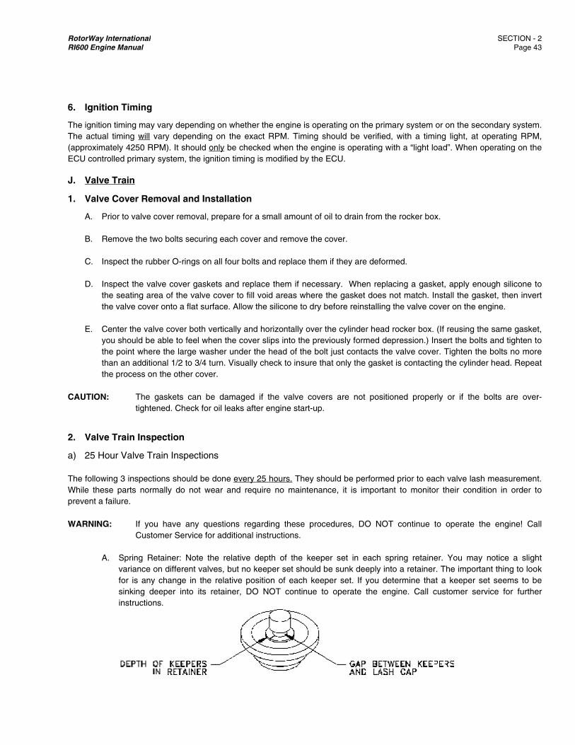
RotorWay IRI600 Engin
6. Ignitio
The ignitionThe actual(approximaECU contro
J. Valve
1. Valve
A. P
B. R
C. In
D. Inthth
E. C
yoththth
CAUTION:
2. Valve
a) 25 Ho
The followiWhile thesprevent a f WARNING
A
International ne Manual
on Timing
n timing may vl timing will vaately 4250 RPMolled primary s
e Train
e Cover Rem
rior to valve co
emove the two
nspect the rubb
nspect the valvhe seating areahe valve cover o
enter the valveou should be ahe point where han an additionhe process on t
: The gatightene
e Train Inspe
our Valve Tra
ing 3 inspectiose parts normafailure.
G: If you Custom
. Spring Retavariance onfor is any csinking deeinstructions
ary depending ary depending M). It should onsystem, the igni
oval and Ins
over removal, p
o bolts securing
ber O-rings on a
ve cover gaskea of the valve conto a flat surfa
e cover both veable to feel whe
the large washnal 1/2 to 3/4 tuthe other cover
askets can be ed. Check for o
ection
in Inspections
ns should be dally do not we
have any quemer Service for
ainer: Note then different valvechange in the eper into its re.
on whether thon the exact
nly be checkedition timing is m
stallation
prepare for a sm
g each cover an
all four bolts an
ets and replacecover to fill voidace. Allow the
ertically and hoen the cover slher under the h
urn. Visually chr.
damaged if toil leaks after e
s
done every 25 ar and require
estions regardadditional inst
e relative deptes, but no keeprelative positioetainer, DO N
e engine is opeRPM. Timing sd when the engmodified by the
mall amount of
nd remove the
nd replace them
e them if necesd areas wheresilicone to dry
orizontally over ips into the prehead of the boeck to insure th
the valve coveengine start-up
hours. They she no maintena
ing these procructions.
th of the keepper set should on of each keeOT continue t
erating on the pshould be verigine is operatine ECU.
oil to drain from
cover.
m if they are de
ssary. When r the gasket dobefore reinstal
the cylinder heeviously formedolt just contactshat only the ga
ers are not po.
hould be perfornce, it is impo
cedures, DO N
per set in eacbe sunk deepl
eper set. If youto operate the
primary systemified, with a timng with a “light
m the rocker bo
eformed.
replacing a gasoes not match. lling the valve c
ead rocker boxd depression.) s the valve covasket is contact
ositioned prope
rmed prior to eortant to monit
NOT continue
h spring retainy into a retaineu determine the engine. Call
m or on the secming light, at oload”. When o
ox.
sket, apply enoInstall the gas
cover on the en
x. (If reusing thInsert the bolts
ver. Tighten theting the cylinde
erly or if the
each valve lashtor their condit
to operate th
ner. You may er. The importaat a keeper secustomer serv
SECTION - 2 Page 43
condary systemoperating RPMoperating on the
ough silicone tosket, then inverngine.
e same gaskets and tighten toe bolts no moreer head. Repea
bolts are over
h measurementtion in order to
he engine! Ca
notice a slighant thing to looet seems to bevice for furthe
2 3
m. M, e
o rt
t, o e
at
r-
t. o
ll
ht k e
er
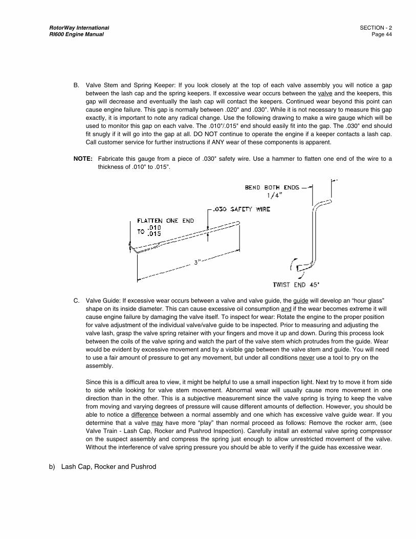
RotorWay IRI600 Engin
B
N
C
b) Lash
International ne Manual
. Valve Stem
between thegap will deccause enginexactly, it isused to mofit snugly if Call custom
OTE: Fabricathickne
. Valve Guideshape on itscause enginfor valve advalve lash, gbetween thewould be evto use a fairassembly.
Since this isto side whidirection thafrom movingable to notidetermine tValve Trainon the suspWithout the
Cap, Rocker
m and Spring Ke lash cap andcrease and evne failure. This s important to nnitor this gap oit will go into t
mer service for f
ate this gauge ess of .010" to .
e: If excessive s inside diametne failure by dadjustment of thegrasp the valvee coils of the vavident by excesr amount of pre
s a difficult areaile looking for an in the otheg and varying dce a differencethat a valve m
n - Lash Cap, Rpect assemblyinterference o
and Pushrod
Keeper: If you d the spring keeventually the la
gap is normallnote any radicaon each valve. he gap at all. Dfurther instructi
from a piece .015".
wear occurs beter. This can caamaging the vae individual valve spring retainealve spring andssive movemenessure to get a
a to view, it migvalve stem m
r. This is a subdegrees of pree between a n
may have moreRocker and Puy and compresof valve spring p
d
look closely aepers. If exces
ash cap will coly between .02al change. UseThe .010"/.015
DO NOT continions if ANY we
of .030" safety
etween a valveause excessivealve itself. To inve/valve guide er with your fingd watch the parnt and by a visny movement,
ght be helpful tmovement. Abbjective measussure will caus
normal assembe “play” than nushrod Inspectss the spring jupressure you s
at the top of essive wear occntact the keep0" and .030". W
e the following 5" end should nue to operate
ear of these com
y wire. Use a
e and valve guie oil consumptinspect for wear
to be inspectegers and movert of the valve sible gap betwebut under all c
to use a small inormal wear wurement since se different ambly and one whnormal proceedion). Carefully ust enough to
should be able t
each valve assurs between th
pers. ContinuedWhile it is not ndrawing to maeasily fit into th the engine if a
mponents is ap
hammer to flat
ide, the guide won and if the wr: Rotate the ened. Prior to meae it up and dowstem which proen the valve st
conditions neve
inspection lightwill usually cathe valve sprinounts of deflec
hich has excesd as follows: Rinstall an exteallow unrestri
to verify if the g
sembly you wihe valve and thd wear beyond
necessary to mke a wire gaughe gap. The .0a keeper conta
pparent.
tten one end o
will develop an wear becomes engine to the proasuring and ad
wn. During this potrudes from thtem and guide.er use a tool to
t. Next try to mause more mong is trying to ction. Howeverssive valve guidRemove the roernal valve spricted movemenguide has exce
SECTION - 2 Page 44
ill notice a gaphe keepers, thisd this point caneasure this gapge which will be030" end shouldacts a lash cap
of the wire to a
“hour glass” extreme it will oper position justing the process look e guide. Wear . You will need pry on the
ove it from sideovement in one
keep the valve, you should bede wear. If you
ocker arm, (seeing compressont of the valveessive wear.
2 4
p s n p e d
p.
a
e e e e u e
or e.

RotorWay International SECTION - 2 RI600 Engine Manual Page 45
Perform if lash is found to be in excess of .008". Rotate the engine to the proper position for valve adjustment of the individual valve to be inspected. (See Valve Adjustment). Loosen the set screw and rocker nut. Remove the rocker nut with set screw. Set it and all additional parts on a clean surface for inspection and replacement in the engine. Carefully remove the rocker and the ball. Remove the pushrod taking note of which end goes against the rocker and which end goes into the pushrod tube. Inspect the lash cap for wear. The top surface which comes in contact with the rocker should not be “dished out”. It should also be relatively snug on the valve and certainly should not rock at all on the valve. Replace as necessary. Visually inspect the rocker and the pushrod for any signs of excessive wear. Roll the pushrod on a flat surface to ensure that it is not bent. Replace any part as necessary. Replace the parts exactly as removed.
CARE MUST BE TAKEN that the pushrod is properly seated in both the rocker and in the lifter, (at the bottom of the pushrod tube). A common error is to have the pushrod improperly located in the rocker arm. Adjust the lash as per instructions in the lash adjustment section. After the adjustment has been made, slowly rotate the engine through two complete revolutions and repeat the valve adjustment as necessary. Continue this process until lash remains unchanged after two complete revolutions. If any parts were replaced, a valve adjustment should be performed hourly until the lash stabilizes.
NOTE: When replacing a lash cap, it is important to seat it on the valve completely. Tapping the lash cap onto the valve with
a plastic tipped hammer may be necessary. It is important that the piston is not near the top of its stroke when tapping on the lash cap. Observing the gap between the lash cap and the keeper will ensure that the lash cap is seated properly.
NOTE: When replacing lash caps it is important to realize that an intake lash cap is different from an exhaust lash cap. The
cavity on an exhaust lash cap is .120"/.125" deep. This depth on an intake lash cap is .145"/.150". Incorrectly installing an intake lash cap on an exhaust valve would result in the lash cap hitting the valve keepers.
c) Camshaft Lift Inspection
This should be done if excessive valve adjustment is repeatedly performed on a valve AND on the valve directly opposite it, suggesting wear or breakdown of a cam lobe. Remove the valve cover from one side of the engine and mount a 1" dial travel indicator exactly parallel with the valve and contacting the “flat” of the valve spring retainer. (This is generally done with a magnetic base type indicator mounted on a fabricated steel plate attached locally to the rocker box.)
Zero the indicator when the engine is in the position to adjust that particular valve. Rotate the engine through two complete revolutions and note the maximum lift generated at the valve. Compare your findings with the specifications in the “Component Specifications And Wear Limits” section of this manual. If you find that a reading appears to be out of tolerance, take a reading on the valve directly opposite the suspect valve to verify that the problem is with the cam lobe and not something else. This is not an inspection that is regularly performed. It should only need to be done at 500 hour intervals unless a problem warrants the inspection.
3. Valve Lash Adjustment
CAUTION: Valve adjustments can ONLY be made after the engine has cooled down and its internal temperature has stabilized at 50° to 90° F. The aluminum case, waterjackets, and cylinder heads will expand with temperature more than the steel pushrods, causing a major difference between “hot” and “cold” valve lash. Adjustments made to a warm engine can result in valves not closing when the engine is cool; conversely, if the engine is too cold when making the adjustments, the lash settings will be too big at operating temperatures.
A. MAKE SURE that the ignition switches are OFF

RotorWay IRI600 Engin
B. Remov C. Rotate
centercranks
NOTE: Th
tobyadth
D. The ro
valve i CAUTION:
E. Use th
blade propera snug
F
NOTE: ITyotrake
Ainof
WARNING
F. If adju
by hanscrew cap. Wmovedshouldand lo
International ne Manual
ve both valve c
e the engine inred over the seshaft degrees a
he only proper o obtain this tooy rotating the djustments. If mhe engine in a c
ocker directly ois fully open, th
: You may noadjust the laopposite the
he feeler gaugebetween the rr size is determg fit and should
Figure 1 - NARR
T IS IMPORTAou are also moain is the contieep records of
ny time a lashndication that yof the correspon
G: BecausExcess
stment is reqund until the feeto 120 in. lbs.
When moving td back and ford first turn the rosen up your a
covers. (See “V
n a counter cloeam of the engat approximate
way to rotate tol are Snap Onmain rotor bl
making a valveclockwise direc
opposite from the #3 exhaust v
otice that thereash at these loce one to be adj
e set which hasocker and the
mined when thed not easily slid
ROW THE REQ
NT to measureonitoring the vainued developmall valve lash a
h measuremenou need to ma
nding lash cap.
se of the desigsive lash will ca
ired, loosen theler gauge is sn. Check the adthe rocker up rth between throcker nut dowadjustment. A l
Valve Cover Re
ockwise directigine case. At ly 90 degrees b
the engine is wn Tools and Maades by hand
e lash adjustmection will cause
the valve, whicvalve is ready f
e are crankshacations. The lajusted at a full o
s been modifielash cap. Whi
e feeler gauge de in and out be
QUIRED FEEL
e the lash befoalve train for exment of excessadjustments.
nt is made andake more regula
n of the camshause damage to
e set screw annug when you
djustment. The and down, if t
he rocker and n snug by hanittle practice w
emoval”)
ion (looking dothis point, two before and afte
with a specially ac Tools. DO Nd. This can caent with the ma the blades to
ch is fully openfor adjustment
aft positions in ash must be proopen position.
d per the followle moving the has a light dra
etween the valv
LER GAUGE A
ore any adjustmxcessive wear sive lash on an
d several of thar adjustments
haft in the RI 1o the lash caps
nd rocker nut. Wmove the rock.004" feeler g
the .006" feelelash cap. It shd is that the tigill give you the
own from the tof the valves
er top dead cen
made tool whiNOT attempt to ause damage ain rotor bladerotate.
, is now readyat the rocker.
which the valvoperly set in th
wing drawing. Mrocker up and
ag when movedve and rocker.)
AS SHOWN. LE
ment is made. Iof parts. A cleany one valve. F
he valves haves. Any lash foun
62F engine, it s, pushrods, ca
With the .004" ker up and dowauge should e
er gauge can bhould not moveghtening of the
right feel for th
top) until the oare FULLY op
nter.
ch grips the flyrotate the engto the rotor ss attached, be
y for adjustmen
ve lash will be e crankshaft po
Measure the cld down, center d back and fort)
EAVE A SMOO
In addition to mar and simple iFor this reason
e a lash of mond in excess of
is essential thamshaft, and th
feeler gauge inwn. Hold the nueasily slide betwbe inserted, it e in and out loset screw cau
he process.)
oval holes in thpen. This happ
ywheel ring geagine by engaginsystem and dis aware that an
nt. Example: If
slightly increasosition which p
learance as folthe rocker on
th. (The feeler
OTH ROUND E
making the corindication of wen, it is recomm
ore than .008",f .008" warrant
at proper lash he timing gear.
n place, tightenut in place andween the rockemust have a loosely. (The rses the nut to
SECTION - 2 Page 4
he flywheel arepens every 180
ar. Two sourcesng the starter osplace lead/lag
ny movement o
the #1 exhaus
sed. Do not replaces the valve
lows: Insert thethe valve. Thegauge must be
EDGE.
rect adjustmenear in the valve
mended that you
this is a cleats an inspection
be maintained
n the rocker nud tighten the seer and the lashight drag wheneason that youback off slightly
2 6
e 0
s or g
of
st
e-e
e e e
nt e u
ar n
d.
ut et h n u y
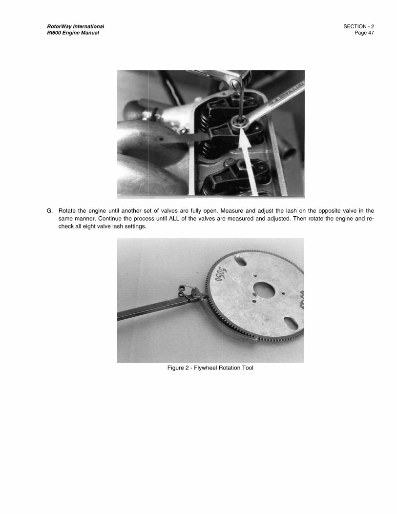
RotorWay IRI600 Engin
G. Rotate
same check
International ne Manual
e the engine umanner. Contiall eight valve
ntil another seinue the procelash settings.
et of valves aress until ALL of
Figure 2
e fully open. Mf the valves are
2 - Flywheel R
Measure and ae measured an
otation Tool
adjust the lash nd adjusted. Th
on the opposhen rotate the
SECTION - 2 Page 47
site valve in theengine and re
2 7
e e-
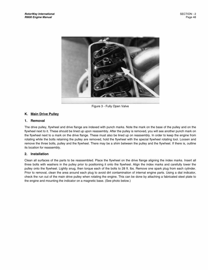
RotorWay IRI600 Engin
K. Main
1. Remo
The drive pflywheel nethe flywheerotating whremove theits location
2. Instal
Clean all sthree boltspulley ontoPrior to remcheck the the engine
International ne Manual
Drive Pulley
oval
pulley, flywheeext to it. These el next to a mahile the bolts ree three bolts, p for reassembl
llation
surfaces of thes with washers o the flywheel. moval, clean thrun out of the and mounting
y
el and drive flanshould be line
ark on the driveetaining the pupulley and the fy.
parts to be rein the pulley Lightly snug, t
he area aroundmain drive pulthe indicator o
Figu
nge are indexeed up upon rease flange. Theseulley are removflywheel. There
eassembled. Pprior to positiothen torque ead each plug to ley when rotati
on a magnetic b
ure 3 - Fully Op
ed with punch mssembly. After e must also beved, hold the flye may be a sh
lace the flywheoning it onto thach of the bolts
avoid dirt coning the enginebase. (See pho
pen Valve
marks. Note thethe pulley is re
e lined up on reywheel with thim between th
eel on the drivhe flywheel. Alis to 28 ft. lbs. Rntamination of i. This can be d
oto below.)
e mark on the emoved, you weassembly. In oe special flywhe pulley and th
e flange alignign the index mRemove one sinternal enginedone by attach
base of the puwill see another order to keep theel rotating tohe flywheel. If t
ng the index mmarks and carespark plug frome parts. Using ahing a fabricate
SECTION - 2 Page 4
ulley and on thepunch mark on
the engine fromool. Loosen andthere is, outline
marks. Insert aefully lower the
m each cylindera dial indicator
ed steel plate to
2 8
e n
m d e
all e r. r, o
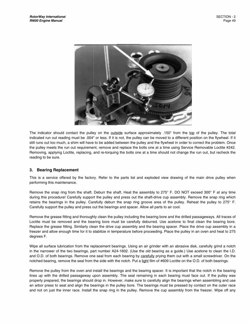
RotorWay IRI600 Engin
The indicaindicated rstill runs outhe pulley Removing,reading to
3. Beari
This is a sperforming Remove thduring this retains theCarefully s Remove thLoctite muReplace thfreezer anddegrees F. Wipe all suin the narroand O.D. onotched be Remove thlines up wproperly pran arbor pand not on
International ne Manual
ator should conun out readingut too much, a meets the run applying Loctbe sure.
ing Replacem
service offeredg this maintena
he snap ring frprocedure! Ca
e bearings in tupport the pull
he grease fittingust be removedhe grease fittingd allow enough
urface lubricatioower of the tw
of both bearingearing, remove
he pulley from twith the drilled repared, the beress to seat an
n just the inner
ntact the pulle must be .004"shim will haveout requiremeite, replacing, a
ment
d by the factornce.
rom the shaft. arefully supporthe pulley. Carey and press o
g and thoroughd and the beag. Similarly cleh time for it to s
on from the rewo bearings, pags. Remove on
the seal from t
the oven and ipassageway u
earings should nd align the ber race. Install t
ey on the outs" or less. If it is
e to be added bnt, remove andand re-torquing
ry. Refer to th
Deburr the shrt the pulley anrefully deburr tout the bearings
hly clean the puaring bore musean the drive cstabilize in tem
placement beaart number A24e seal from eathe side with th
nstall the bearupon assemblydrop in. Howe
earings in the pthe snap ring i
side surface as not, the pulleybetween the pud replace the bg the bolts one
e parts list an
aft. Heat the and press out ththe snap ring s and spacer. A
ulley including tst be carefullyup assembly a
mperature befor
arings. Using a4-1602. (Use t
ach bearing by he notch. Put a
rings and the by. The seal remever, make surepulley bore. Thn the pulley. R
pproximately .y can be move
ulley and the flybolts one at a te at a time sho
nd exploded vi
assembly to 27he shaft-drive cgroove area o
Allow all parts t
the bearing boy deburred. Usand the bearingre proceeding.
an air grinder whe old bearingcarefully pryin
a light film of #6
bearing spacer.maining in eace to carefully ahe bearings muRemove the cu
150" from theed to a differenywheel in ordertime using Servould not change
ew drawing of
75° F. DO NOcup assembly. of the pulley. Rto air cool.
re and the drillese acetone to g spacer. PlacePlace the pulle
with an abrasiveg as a guide.) Ug them out wit
609 Loctite on t
. It is importantch bearing mualign the bearinust be pressedup assembly fr
e top of the punt position on thr to correct the vice Removabe the run out, b
f the main driv
T exceed 300°Remove the s
Reheat the pu
ed passagewafinal clean thee the drive cupey in an oven a
e disk, carefullUse acetone toh a small screwthe O.D. of bot
t that the notchst face out. If
ngs when assed by contact onrom the freeze
SECTION - 2 Page 4
ulley. The totahe flywheel. If problem. Once
le Loctite #242but recheck the
ve pulley when
° F at any timesnap ring whichulley to 275° F
ays. All traces oe bearing borep assembly in aand heat to 275
ly grind a notcho clean the I.Dwdriver. On theh bearings.
h in the bearingthe pulley wasmbling and use
n the outer raceer. Wipe off any
2 9
al it e
2. e
n
e h
F.
of e. a 5
h D. e
g s e e y

RotorWay International SECTION - 2 RI600 Engine Manual Page 50
moisture contamination on the shaft using acetone. Put a light film of #609 loctite on the portion of the shaft which will contact the top bearing. Similarly place a light film on the I.D. of the bottom bearing. Immediately install the cup assembly. It should drop in. If the press is required, only light pressure is allowed or damage to the bearings could occur. Wipe off any excess Loctite from the bottom of the shaft and install the snap ring. Allow the assembly to cool and check the bearings for freedom of movement by rotating the drive cup in the pulley. If the bearings feel tight or rough, lightly tap the shaft of the drive cup with an aluminum or brass hammer. This will usually free up the bearings. Slowly pump 7 shots of grease into the pulley while rotating the drive cup. (Refer to GREASE REQUIREMENTS AND SPECIFICATIONS FOR THE MAIN DRIVE PULLEY in Section 1.)

RotorWay International SECTION - 3 RI600 Engine Manual Page 51
SECTION 3: Start-up and Initial Run-in Procedures
A. Introduction It is important that you read this entire manual as vital procedures are contained throughout. Each section contains relevant information essential to properly start and operate the powerplant. It is mandatory that you read Section 2 (Individual System Procedures) prior to starting the power plant for the first time. Failure to follow all of these procedures may damage the engine. Monitor the RI 600 engine very closely especially during the first 5 hours of operation.
WARNING: The engine can be started without the main rotor blades installed, however: A. The pitch control rods of the rotor system must be removed from the rotating swash plate. B. All remaining components of the drive system must be connected. C. The engine must not be operated above 2000 RPM. D. The engine must not be run at idle for extended periods of time.
WARNING: When the starter is engaged, all drive train components will turn, including the main rotor blades if they are
installed. WARNING: It is VERY IMPORTANT to not exceed an idle until the coolant temperature reaches 160° F. Oil
temperature must also be in the green range on the gauge. DO NOT idle the engine for long, extended periods of time. Once the coolant and oil temperatures reach the green range on the gauges, the RPM and LOAD should be varied for most effective “run in”. The engine should NEVER be idled for longer than is necessary. On shut down, idle the engine only long enough to cool down and stabilize the engine components. A water temperature drop of 5-10° F after set down from a hover is adequate for component stabilization. Follow the maintenance requirements closely. Frequent inspections will expose the need for adjustments before problems and damage occur. Individual experiences may also direct you toward ADDITIONAL inspections and adjustments beyond the increments outlined in this manual. WARNING: DO NOT operate the RI 600 powerplant in a rough running condition under load. (High frequency vibration
or roughness in the engine is readily felt through the pedals in the ship). The initial start-up procedure on the engine will require at least two people. Each person should have definite responsibilities. A comprehensive review of all procedures and related duties ahead of time will eliminate most of the confusion during the exciting first few minutes of engine operation. Proper preplanning and complete comprehension of all material contained in this manual are essential ingredients to a successful operation of the powerplant.
B. First Start Outline Summary
1. Prepare the Fuel System, Cooling System, Oil System and Ignition System for first start-up by complying with the information contained in Section 2.
2. Wear safety glasses and have a fire extinguisher nearby. Be careful of all rotating parts, especially the main rotor
blades, the tail rotor blades, and belt assemblies.
3. It is advisable to perform these procedures away from other people because of the distractions and danger a crowd presents.
RotorWay International SECTION - 3 RI600 Engine Manual Page 52
4. Pay special attention to:
A. Leaks, which present a fire hazard B. Oil pressure C. Water temperature D. Rotating parts
5. We advise you to attend our training program prior to starting the engine. The hands-on instruction regarding the
proper care and operation of the engine is extremely valuable to even the best mechanic.
C. Maintenance Requirements
FIRST HOUR SERVICE
1. MEASURE AND ADJUST VALVE LASH AND INSPECT VALVE TRAIN: If any adjustment is necessary at one hour, valve
adjustment should be repeated hourly until the lash stabilizes. (Initial “break in” of the valve train may require several hourly adjustments. It is extremely important to make these inspections and adjustments.)
2. RE-TORQUE BOLTS: Re-torque the bolts on the exhaust manifold flanges, intake manifolds, and waterjacket elbows. 3. INSPECT COOLING SYSTEM: Check entire system, including engine, for any sign of leakage. Make sure all hose clamps
are installed past the bead or flare on the end of the adjoining tube or fitting and re-tighten them. Check the hoses, making sure there is no interference with vibrating or rotating parts or any sign of heat damage. Re-bleed the cooling system at the water pump, radiator, and engine.
4. INSPECT OIL SYSTEM: Check entire system for any sign of leakage. Check the security of all oil line connections. Also
check the lines for proper clearance from other parts and heat sources. 5. INSPECT FUEL SYSTEM: Check the security of all fuel hoses and check for any signs of leakage on the entire system. 6. INSPECT IGNITION SYSTEM: Check all wiring, including spark plug wires, for proper mounting and condition. Replace any
wire that shows any sign of damage. 7. INSPECT THROTTLE CONTROL: Check return spring and linkage for proper adjustment and freedom of movement. 8. INSPECT EXHAUST SYSTEM: Check the entire exhaust system for cracks and leaks. A proper fit of each exhaust
manifold to its mating port is important. This can be verified while idling the engine and positioning your finger approximately 1/2" away from the exhaust ports. Test all the way around the circumference of each port for any escaping gases. If no turbulence is felt within the proximity, you can be assured that the system will be sufficiently leak free at full RPM.
Check the security and condition of all exhaust related shielding. NOTE: After first run-up, retighten exhaust bolts.
RotorWay International SECTION - 3 RI600 Engine Manual Page 53
WARNING: All four gaskets should be replaced at the first hint of flange leakage. Any type of exhaust system leak may allow carbon monoxide fumes to enter the cabin area. Exposure to these fumes can be fatal and any indication of leakage must be corrected before operation is continued.
9. INSPECT FADEC WIRING: With engine idling, carefully wiggle all FADEC system connector plugs and wires. Pay special
attention to the ECU plugs and wiring bundle. If any problem is encountered, refer to the diagnostic section for the FADEC system.
FIRST FIVE HOUR SERVICE
1. TORQUE CYLINDER HEAD BOLTS: The engine must be cold when torquing these bolts. (See “Cylinder Head Torque
Sequence” in Section 1.) Remove rockers as necessary to access all head bolts. Valve lash adjustment must be done after replacing the rockers. It is advisable to perform this procedure in conjunction with the required valve lash adjustment sequence.
2. INSPECT AND CLEAN THE FUEL PRE-FILTER: See Fuel System components section. 3. REPEAT ALL FIRST HOUR ITEMS
FIRST TEN HOUR SERVICE
1. CHANGE OIL AND FILTER 2. REPEAT ALL FIRST HOUR ITEMS
FIRST 25 HOUR SERVICE
1. TORQUE CYLINDER HEAD BOLTS: The engine must be cold when torquing these bolts. (See “Cylinder Head
Torque Sequence” in Section 1.) Remove rockers as necessary to access all head bolts. Valve lash adjustment must be done after replacing the rockers. It is advisable to perform this procedure in conjunction with the required valve lash adjustment sequence.
2. PERFORM ALL “REGULAR” 25 HOUR SERVICE ITEMS
RotorWay International SECTION - 4 RI600 Engine Manual Page 54
SECTION 4: Inspection and Maintenance Schedule
A. Introduction The following schedule is presented as a guide to the regular maintenance required on the engine. It should be followed exactly, as all of the procedures are essential to achieving a long lasting and reliable powerplant. In no way does this mean this is all of the maintenance YOUR engine may require! By closely monitoring all systems and analyzing any problems you encounter, you may find that you need to increase the amount of the attention you give to an individual system or component. Obviously if any problem is encountered either at a regular maintenance interval or during post or pre flight inspections, immediate action must be taken and you will need to closely monitor the situation until you are certain that the problem is completely resolved. Each service should be performed at every increment in the life of the powerplant. The procedures necessary to complete each maintenance item are covered in the Individual System Procedures section of the manual. WARNING: After any rework of the cylinder heads or waterjackets, the inspection and maintenance schedule for a new
engine should be followed.
B. 25 Hour Service NOTE: The following maintenance items are to be performed EVERY 25 hours.
1. SERVICE AIR FILTER: Clean as necessary and inspect for damage.
2. GREASE MAIN DRIVE PULLEY: Refer to Section 1 for procedure and for correct type and quantity of grease.
3. TORQUE CYLINDER HEAD BOLTS: The engine must be cold when torquing these bolts. (See “Cylinder Head Torque Sequence” in Section 1.) Remove rockers as necessary to access all head bolts. Valve lash adjustment must be done after replacing the rockers. It is advisable to perform this procedure in conjunction with the required valve lash adjustment sequence.
4. MEASURE AND ADJUST VALVE LASH AND INSPECT VALVE TRAIN: Also, if any initial measurement is in
excess of .008", inspect the lash cap for wear and repeat valve adjustment at one hour intervals until the lash stabilizes. If repeated excess lash is encountered, all related valve train components should be inspected.
5. INSPECT COOLING SYSTEM: Check entire system, including engine, for any sign of leakage. Check the security of
all hoses, and make sure all hose clamps are installed past the bead or flare on the end of the adjoining tube or fitting. Re-tighten all hose clamps. Check the hoses, making sure there is no interference with vibrating or rotating parts or any sign of heat damage.
6. INSPECT OIL SYSTEM: Check entire system for any sign of leakage. Check the security of all oil line connections.
Also, check the lines for proper clearance from heat sources and other parts.
7. INSPECT FUEL SYSTEM: Check the security of all fuel hoses and check for any signs of leakage on the entire system.
RotorWay International SECTION - 4 RI600 Engine Manual Page 55
8. INSPECT EXHAUST SYSTEM: Check entire exhaust system for cracks and leaks. Proper fit of each exhaust manifold to its mating port is important. Proper fit can be verified while idling the engine and positioning your finger approximately 1/2" away from the exhaust ports. Test all the way around the circumference of each port for any escaping gases. If no turbulence is felt within the proximity, the system will be sufficiently leak free at full RPM.
Also check the security and condition of all exhaust related shielding.
9. INSPECT IGNITION SYSTEM: Check all wiring, including spark plug wires, for proper mounting and condition. Replace any wire that shows any sign of damage.
10. RE-TORQUE BOLTS: Re-torque the bolts on the exhaust manifold flanges, intake manifolds, and waterjacket
elbows.
11. INSPECT THROTTLE CONTROL: Check return spring and linkage for proper adjustment and freedom of movement. Check cable ends and cable for wear.
12. CHANGE OIL AND FILTER: Change oil and filter every six months even if 25 hours of operation has not yet
occurred.
C. 50 Hour Service NOTE: The following maintenance item is to be performed EVERY 50 hours.
1. SPARK PLUGS: Re-gap all spark plugs to specification. Check all spark plugs for proper burning. The central ceramic insulator should be a light tan in color, the outside barrel should be light charcoal to dark brown in color. (Prolonged idling of the engine will cause a black soot to form on the spark plugs which will shield visibility of the above determination of colors.) The electrode should have sharp square edges. Replace a spark plug if any sign of wear or damage is evident. Clean and apply a light film of anti-seize to the threads before re-installing the spark plugs.
2. PERFORM ALL REGULAR 25 HOUR SERVICE ITEMS
D. 100 Hour Service NOTE: The following maintenance items are to be performed EVERY 100 hours.
1. REPLACE SPARK PLUGS
2. TEST CYLINDER LEAKAGE: Using a cylinder leak down tester, measure the percentage of leakage of each cylinder. If reading is above 15%, determine the source of leakage and repair. With tester hooked up, listen for air leakage at:
Tail pipe (leaking exhaust valve) Plenum intake (leaking intake valve) Oil sump breather (leaking by piston rings)
3. REPLACE FUEL FILTER
4. PERFORM ALL REGULAR 25 AND 50 HOUR SERVICE ITEMS
E. 250 Hour Service NOTE: The following maintenance items are to be performed EVERY 250 hours.
RotorWay International SECTION - 4 RI600 Engine Manual Page 56
1. REPLACE AIR FILTER
2. REPLACE ALL WATER HOSES: Replace all water hoses, hose clamps and coolant. Replace every five years even
if 250 hours of operation has not yet occurred.
3. REPLACE CAM GEAR
4. REBUILD CYLINDER HEADS (IF USING 100 LOW LEAD OR LEADED AUTOMOTIVE GASOLINE): Specifications have been given to perform this service and all of the necessary parts are available from the factory. This is a critical and complex task and should not be attempted by anyone who is not familiar with all aspects of aluminum cylinder head rebuilding. This service is offered by the factory.
5. PERFORM ALL REGULAR 25 AND 50 HOUR SERVICE ITEMS
F. 500 Hour Service NOTE: The following maintenance items are to be performed EVERY 500 hours.
1. REBUILD CYLINDER HEADS (IF USING UNLEADED GASOLINE): Specifications have been given to perform this service and all of the necessary parts are available from the factory. This is a critical and complex task and should not be attempted by anyone who is not familiar with all aspects of aluminum cylinder head rebuilding. This service is offered by the factory.
NOTE: If using 100 low lead aviation gasoline or leaded automotive gasoline, cylinder heads must be rebuilt every 250 hours.
2. INSPECT CAMSHAFT LIFT AND END PLAY
3. REPLACE MAIN DRIVE PULLEY BEARINGS: This service is offered by the factory.
4. PERFORM ALL REGULAR 25, 50, 100 AND 250 HOUR SERVICE ITEMS
G. 1000 Hour Service NOTE: The following maintenance items are to be performed EVERY 1000 hours.
1. REPLACE SPARK PLUG WIRES
2. REPLACE FUEL INJECTORS
3. REPLACE FUEL HOSES
4. COMPLETE ENGINE OVERHAUL: This is a critical and complex task. It is recommended that this service be performed only by the factory and not by anyone else even if they are familiar with all aspects of internal engine overhaul. However, specifications have been given to perform this service and all the necessary parts are available from the factory.
5. PERFORM ALL REGULAR 25, 50, 100, 250 AND 500 HOUR SERVICE ITEMS
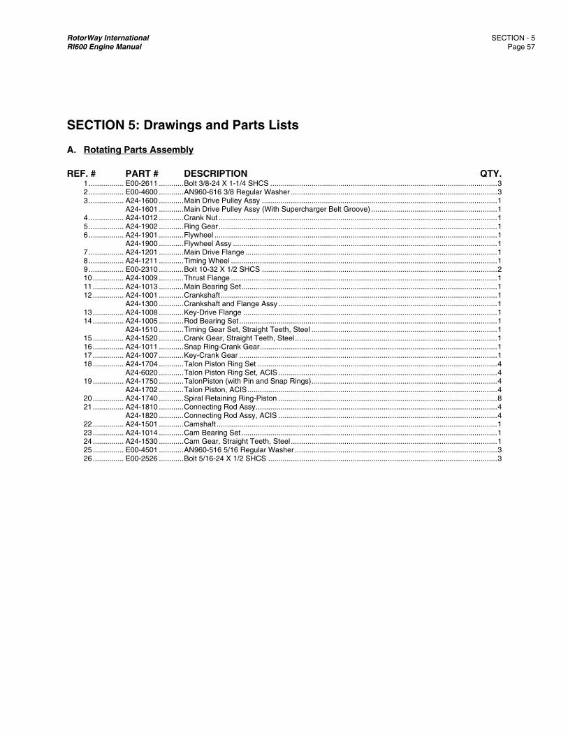
RotorWay International SECTION - 5 RI600 Engine Manual Page 57
SECTION 5: Drawings and Parts Lists
A. Rotating Parts Assembly
REF. # PART # DESCRIPTION QTY. 1 ................. E00-2611 ............ Bolt 3/8-24 X 1-1/4 SHCS .............................................................................................................. 3 2 ................. E00-4600 ............ AN960-616 3/8 Regular Washer .................................................................................................... 3 3 ................. A24-1600 ............ Main Drive Pulley Assy .................................................................................................................. 1 A24-1601 ............ Main Drive Pulley Assy (With Supercharger Belt Groove) ............................................................. 1 4 ................. A24-1012 ............ Crank Nut ....................................................................................................................................... 1 5 ................. A24-1902 ............ Ring Gear ....................................................................................................................................... 1 6 ................. A24-1901 ............ Flywheel ......................................................................................................................................... 1 A24-1900 ............ Flywheel Assy ................................................................................................................................ 1 7 ................. A24-1201 ............ Main Drive Flange .......................................................................................................................... 1 8 ................. A24-1211 ............ Timing Wheel ................................................................................................................................. 1 9 ................. E00-2310 ............ Bolt 10-32 X 1/2 SHCS .................................................................................................................. 2 10 ............... A24-1009 ............ Thrust Flange ................................................................................................................................. 1 11 ............... A24-1013 ............ Main Bearing Set ............................................................................................................................ 1 12 ............... A24-1001 ............ Crankshaft ...................................................................................................................................... 1 A24-1300 ............ Crankshaft and Flange Assy .......................................................................................................... 1 13 ............... A24-1008 ............ Key-Drive Flange ........................................................................................................................... 1 14 ............... A24-1005 ............ Rod Bearing Set ............................................................................................................................. 1 A24-1510 ............ Timing Gear Set, Straight Teeth, Steel .......................................................................................... 1 15 ............... A24-1520 ............ Crank Gear, Straight Teeth, Steel .................................................................................................. 1 16 ............... A24-1011 ............ Snap Ring-Crank Gear ................................................................................................................... 1 17 ............... A24-1007 ............ Key-Crank Gear ............................................................................................................................. 1 18 ............... A24-1704 ............ Talon Piston Ring Set .................................................................................................................... 4 A24-6020 ............ Talon Piston Ring Set, ACIS .......................................................................................................... 4 19 ............... A24-1750 ............ TalonPiston (with Pin and Snap Rings) .......................................................................................... 4 A24-1702 ............ Talon Piston, ACIS ......................................................................................................................... 4 20 ............... A24-1740 ............ Spiral Retaining Ring-Piston .......................................................................................................... 8 21 ............... A24-1810 ............ Connecting Rod Assy ..................................................................................................................... 4 A24-1820 ............ Connecting Rod Assy, ACIS .......................................................................................................... 4 22 ............... A24-1501 ............ Camshaft ........................................................................................................................................ 1 23 ............... A24-1014 ............ Cam Bearing Set ............................................................................................................................ 1 24 ............... A24-1530 ............ Cam Gear, Straight Teeth, Steel .................................................................................................... 1 25 ............... E00-4501 ............ AN960-516 5/16 Regular Washer .................................................................................................. 3 26 ............... E00-2526 ............ Bolt 5/16-24 X 1/2 SHCS ............................................................................................................... 3
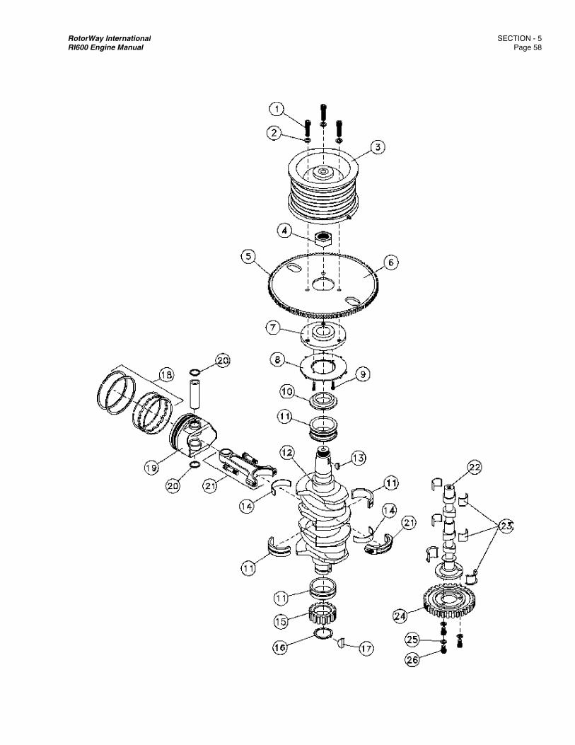
RotorWay IRI600 Engin
International ne Manual
SECTION - Page 5
5 8
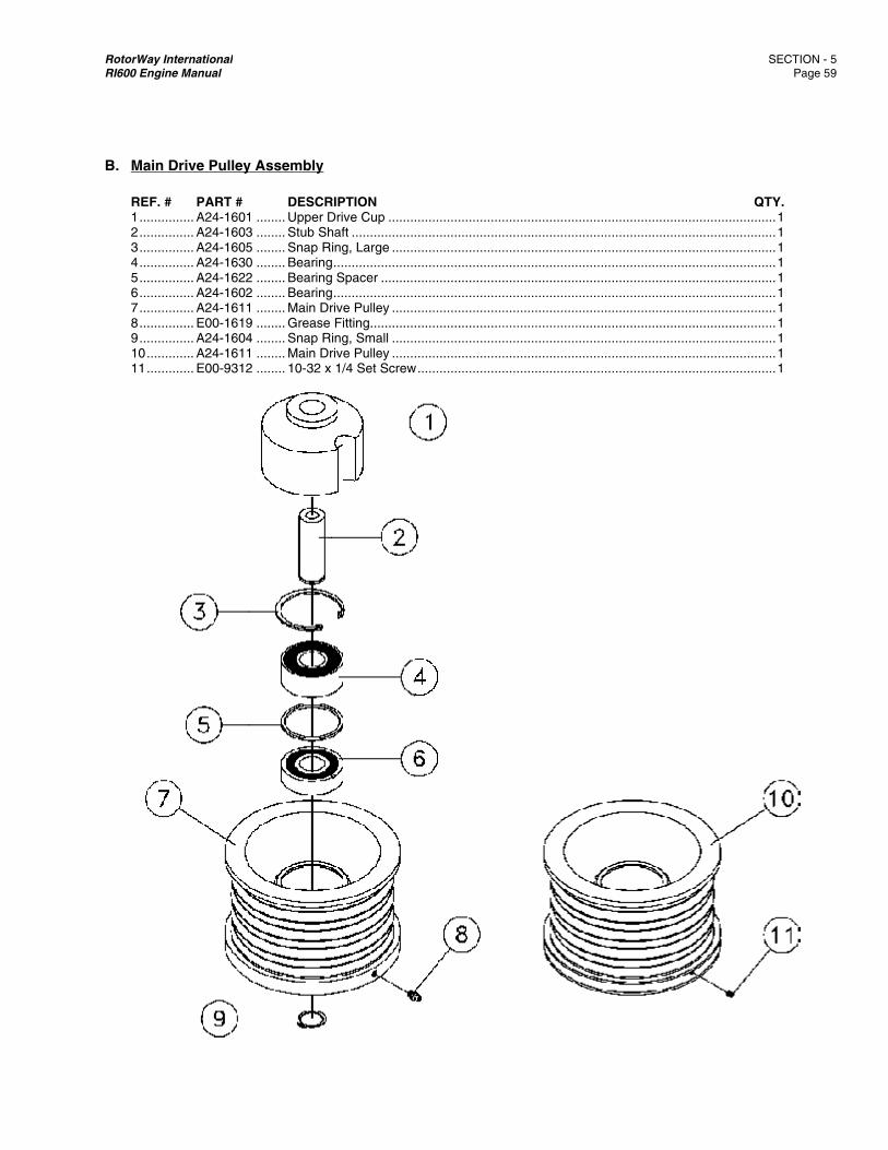
RotorWay IRI600 Engin
B. Main REF. # 1 ........ 2 ........ 3 ........ 4 ........ 5 ........ 6 ........ 7 ........ 8 ........ 9 ........ 10 ...... 11 ......
International ne Manual
Drive Pulley
# PART # ........ A24-1601........ A24-1603........ A24-1605........ A24-1630........ A24-1622........ A24-1602........ A24-1611........ E00-1619........ A24-1604........ A24-1611........ E00-9312
y Assembly
DESCR1 ........ Upper D3 ........ Stub Sh5 ........ Snap Ri0 ........ Bearing2 ........ Bearing2 ........ Bearing1 ........ Main Dr9 ........ Grease 4 ........ Snap Ri1 ........ Main Dr2 ........ 10-32 x
RIPTIONDrive Cup ........haft ..................ing, Large ....... ....................... Spacer .......... .......................
rive Pulley .......Fitting.............ing, Small .......rive Pulley .......1/4 Set Screw
.......................
.......................
.......................
.......................
.......................
.......................
.......................
.......................
.......................
.......................w ......................
.......................
.......................
.......................
.......................
.......................
.......................
.......................
.......................
.......................
.......................
.......................
.......................
.......................
.......................
.......................
.......................
.......................
.......................
.......................
.......................
.......................
.......................
.......................
.......................
.......................
.......................
.......................
.......................
.......................
.......................
.......................
.......................
.......................
SECTION - Page 5
QTY. ........ 1 ........ 1 ........ 1 ........ 1 ........ 1 ........ 1 ........ 1 ........ 1 ........ 1 ........ 1 ........ 1
5 9
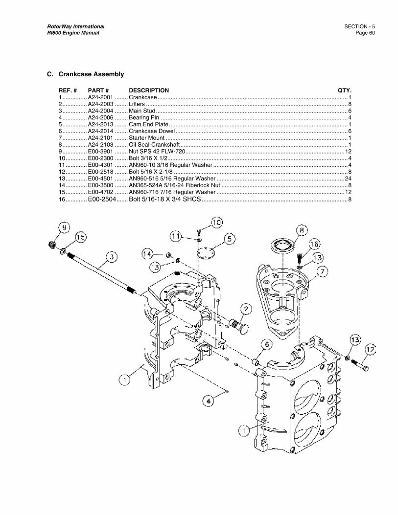
RotorWay IRI600 Engin
C. Crank REF. # 1 ........ 2 ........ 3 ........ 4 ........ 5 ........ 6 ........ 7 ........ 8 ........ 9 ........ 10 ...... 11 ...... 12 ...... 13 ...... 14 ...... 15 ...... 16 ......
International ne Manual
kcase Assem
# PART # ........ A24-2001........ A24-2003........ A24-2004........ A24-2006........ A24-2013........ A24-2014........ A24-2101........ A24-2103........ E00-3901........ E00-2300........ E00-4301........ E00-2518........ E00-4501........ E00-3500........ E00-4702........ E00-250
mbly
DESCR1 ........ Crankca3 ........ Lifters ..4 ........ Main St6 ........ Bearing3 ........ Cam En4 ........ Crankca1 ........ Starter M3 ........ Oil Seal1 ........ Nut SPS0 ........ Bolt 3/11 ........ AN960-8 ........ Bolt 5/11 ........ AN960-0 ........ AN365-2 ........ AN960-04 ....... Bolt 5/1
RIPTIONase .........................................ud ................... Pin ................
nd Plate ...........ase Dowel .......Mount .............l-Crankshaft ....S 42 FLW-720 .6 X 1/2............10 3/16 Regula6 X 2-1/8 ........516 5/16 Regu524A 5/16-24 F716 7/16 Regu16-18 X 3/4 S
.......................
.......................
.......................
.......................
.......................
.......................
.......................
.......................
.......................
.......................ar Washer .............................ular Washer ....Fiberlock Nut .ular Washer ....SHCS .............
.......................
.......................
.......................
.......................
.......................
.......................
.......................
.......................
.......................
.......................
.......................
.......................
.......................
.......................
.......................
.......................
.......................
.......................
.......................
.......................
.......................
.......................
.......................
.......................
.......................
.......................
.......................
.......................
.......................
.......................
.......................
.......................
.......................
.......................
.......................
.......................
.......................
.......................
.......................
.......................
.......................
.......................
.......................
.......................
.......................
.......................
.......................
.......................
SECTION - Page 60
QTY. ........ 1 ........ 8 ........ 6 ........ 4 ........ 1 ........ 6 ........ 1 ........ 1 ...... 12 ........ 4........ 4 ........ 8...... 24 ........ 8 ...... 12 ........ 8
5 0

RotorWay International SECTION - 5 RI600 Engine Manual Page 61
D. Lower Cover Assembly REF. # PART # DESCRIPTION QTY. 1 ............... A24-2007 ........ Lower Cover ................................................................................................................. 1 2 ............... A24-2010 ........ Oil Exit Fitting ............................................................................................................... 1 3 ............... A24-2015 ........ Bushing-Lower Cover ................................................................................................... 1 4 ............... A24-2016 ........ O-Ring (Main Galley) ................................................................................................... 1 5 ............... A24-2201 ........ Oil Temp Sender .......................................................................................................... 1 6 ............... A24-2202 ........ Lower Cover Dowel ...................................................................................................... 2 7 ............... A24-2230 ........ 90° Oil Hose Fitting ...................................................................................................... 2 A24-2231 ........ -8 Tee, 3/8 NPT on Side (ACIS) ................................................................................... 1 E38-6460 ........ -8 to -6 Adapter (ACIS) ................................................................................................ 1 8 ............... A24-2401 ........ Oil Pump Cover ............................................................................................................ 1 9 ............... A24-2402 ........ Oil Pump Cover O-Ring (Small) ................................................................................... 1 10 ............. A24-2403 ........ Oil Pump Cover O-Ring (Large) ................................................................................... 1 11 ............. A24-2410 ........ Oil Pump Assy .............................................................................................................. 1 12 ............. A24-2450 ........ Piston ........................................................................................................................... 1 13 ............. A24-2451 ........ Spring ........................................................................................................................... 1 14 ............. A24-2452 ........ Spring Backing Plate .................................................................................................... 1 15 ............. A24-2453 ........ Gasket (Regulator) ....................................................................................................... 1 16 ............. A24-2454 ........ Oil Pressure Adjustment Plug ...................................................................................... 1 17 ............. A24-2455 ........ O-Ring (Regulator) ....................................................................................................... 1 18 ............. A24-2220 ........ Oil Drain Plug (1/4 Pipe) .............................................................................................. 1 19 ............. E00-2529 ........ Bolt 5/16-18 X 2 ........................................................................................................... 2 20 ............. A24-2240 ........ 45° Oil Hose Fitting ...................................................................................................... 1 21 ............. E00-4501 ........ AN960-516 5/16 Regular Washer .............................................................................. 14 22 ............. E00-3501 ........ AN316-5R 5/16 Jam Nut .............................................................................................. 1 23 ............. E00-2530 ........ Bolt 5/16-24 X 2 SHCS ................................................................................................ 1 24 ............. E00-2527 ........ Bolt 5/16-18 X 1-1/2 ..................................................................................................... 1
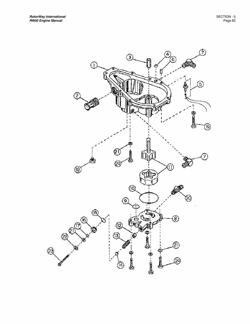
RotorWay International SECTION - 5 RI600 Engine Manual Page 62
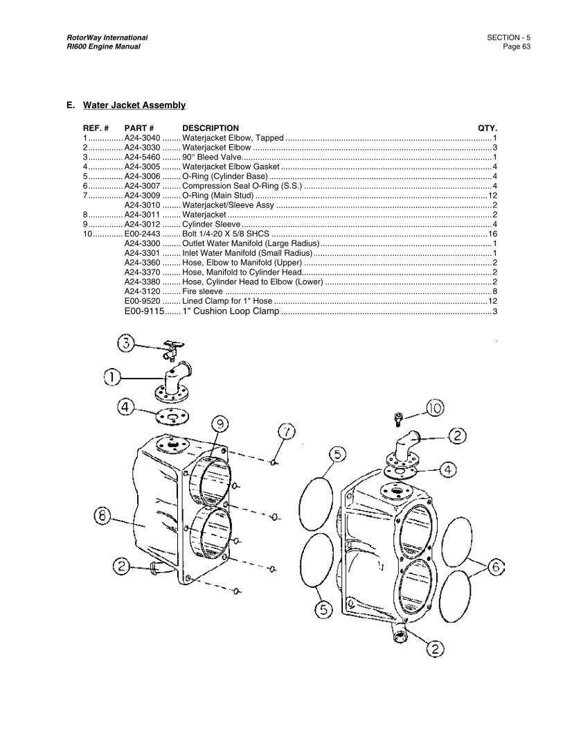
RotorWay IRI600 Engin
E. Wate REF. # 1 ........ 2 ........ 3 ........ 4 ........ 5 ........ 6 ........ 7 ........ 8 ........ 9 ........ 10 ......
International ne Manual
r Jacket Ass
# PART # ........ A24-3040........ A24-3030........ A24-5460........ A24-3005........ A24-3006........ A24-3007........ A24-3009
A24-3010........ A24-3011........ A24-3012........ E00-2443
A24-3300A24-3301A24-3360A24-3370A24-3380A24-3120E00-9520E00-911
sembly
DESCR0 ........ Waterja0 ........ Waterja0 ........ 90° Blee5 ........ Waterja6 ........ O-Ring 7 ........ Compre9 ........ O-Ring 0 ........ Waterja1 ........ Waterja2 ........ Cylinder3 ........ Bolt 1/40 ........ Outlet W1 ........ Inlet Wa0 ........ Hose, E0 ........ Hose, M0 ........ Hose, C0 ........ Fire slee0 ........ Lined C5 ....... 1" Cush
RIPTIONacket Elbow, Taacket Elbow .....ed Valve..........
acket Elbow Ga(Cylinder Base
ession Seal O-R(Main Stud) ....
acket/Sleeve Asacket ................r Sleeve ..........-20 X 5/8 SHC
Water Manifold ater Manifold (SElbow to ManifoManifold to CyliCylinder Head teve .................lamp for 1" Hohion Loop Cla
apped ...........................................................
asket ...............e) ....................Ring (S.S.) ............................ssy ...............................................................
CS ...................(Large Radius
Small Radius) .old (Upper) .....nder Head ......o Elbow (Lowe.......................
ose ..................amp ...............
.......................
.......................
.......................
.......................
.......................
.......................
.......................
.......................
.......................
.......................
.......................s) ..........................................................................................
er) ........................................................................................
.......................
.......................
.......................
.......................
.......................
.......................
.......................
.......................
.......................
.......................
.......................
.......................
.......................
.......................
.......................
.......................
.......................
.......................
.......................
.......................
.......................
.......................
.......................
.......................
.......................
.......................
.......................
.......................
.......................
.......................
.......................
.......................
.......................
.......................
.......................
.......................
.......................
.......................
SECTION - Page 63
QTY. ........ 1 ........ 3 ........ 1 ........ 4 ........ 4 ........ 4 ...... 12 ........ 2 ........ 2 ........ 4 ...... 16 ........ 1 ........ 1 ........ 2 ........ 2 ........ 2 ........ 8 ...... 12 ........ 3
5 3
RotorWay International SECTION - 5 RI600 Engine Manual Page 64
F. Cylinder Head Assembly REF.# PART # DESCRIPTION QTY. 1 ............... A24-4002 ........ Intake Valve ................................................................................................................. 4 2 ............... A24-4003 ........ Intake Valve Seat ......................................................................................................... 4 A24-4004 ........ Intake Valve Guide ....................................................................................................... 4 3 ............... A24-4055 ........ Exhaust Valve .............................................................................................................. 4 4 ............... A24-4056 ........ Exhaust Valve Seat ...................................................................................................... 4 5 ............... A24-4057 ........ Exhaust Valve Guide .................................................................................................... 4 6 ............... A24-4008 ........ Valve Spring ................................................................................................................. 8 7 ............... A24-4009 ........ Spring Shim ................................................................................................................. 8 8 ............... A24-4010 ........ Spring Retainer ............................................................................................................ 8 9 ............... A24-4011 ........ Spring Keeper (2 per valve) ....................................................................................... 16 10 ............. A24-4012 ........ Rocker Arm Stud .......................................................................................................... 8 11 ............. A24-4013 ........ Rocker Arm .................................................................................................................. 8 12 ............. A24-4014 ........ Pivot Ball ...................................................................................................................... 8 13 ............. A24-4015 ........ O-Ring (Valve Stem) .................................................................................................... 8 14 ............. A24-4017 ........ Gasket (Valve Cover) ................................................................................................... 2 15 ............. A24-4018 ........ O-Ring (Valve Cover) ................................................................................................... 4 A24-4040 ........ Lash Cap (Intake) ......................................................................................................... 4 16 ............. A24-4050 ........ Lash cap (Exhaust) ...................................................................................................... 4 17 ............. A24-5430 ........ FADEC Water Temp Sensor (Install near Cyl. #2) ....................................................... 1 18 ............. A24-2201 ........ Water Temp. Sender (Install near Cyl. #4) ................................................................... 1 19 ............. A24-4090 ........ Cylinder Head (With Seats and Guides) ...................................................................... 2 A24-4095 ........ Cylinder Head (With Valves) ........................................................................................ 2 A24-4100 ........ Cylinder Head Complete Assy ..................................................................................... 2 20 ............. A24-4110 ........ Pushrod ........................................................................................................................ 8 21 ............. A24-4204 ........ Pushrod Tube Seals ................................................................................................... 16 22 ............. A24-4260 ........ Pushrod Tube Assy ...................................................................................................... 8 23 ............. A24-4270 ........ Pushrod Tube O-Ring ................................................................................................ 16 24 ............. A24-4280 ........ Pushrod Tube Seal Ring ............................................................................................ 16 25 ............. A24-4300 ........ Polyloc Assy ................................................................................................................. 8 26 ............. A24-4075 ........ 90° Oil Drain Fitting ...................................................................................................... 2 27 ............. A24-4071 ........ Water Hose Fitting ....................................................................................................... 4 28 ............. A24-4030 ........ Valve Cover (with Gasket) ........................................................................................... 2 29 ............. E00-2430 ........ Bolt 1/4-20 X 2-3/4 ....................................................................................................... 4 30 ............. E00-4402 ........ MS15795-10 1/4 Large Washer ................................................................................... 4 A24-4036 ........ Bolt 3/8 X 2 12 Point ................................................................................................... 4 A24-4037 ........ Bolt 3/8 X 3-1/8 12 Point ............................................................................................. 4 31 ............. A24-4038 ........ Bolt 3/8 X 4-5/8 12 Point ............................................................................................. 8 32 ............. E00-4600 ........ AN960-616 3/8 Regular Washer ................................................................................ 20
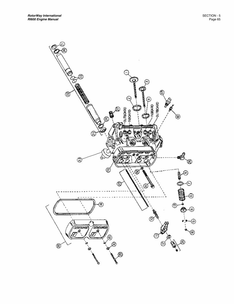
RotorWay International SECTION - 5 RI600 Engine Manual Page 65
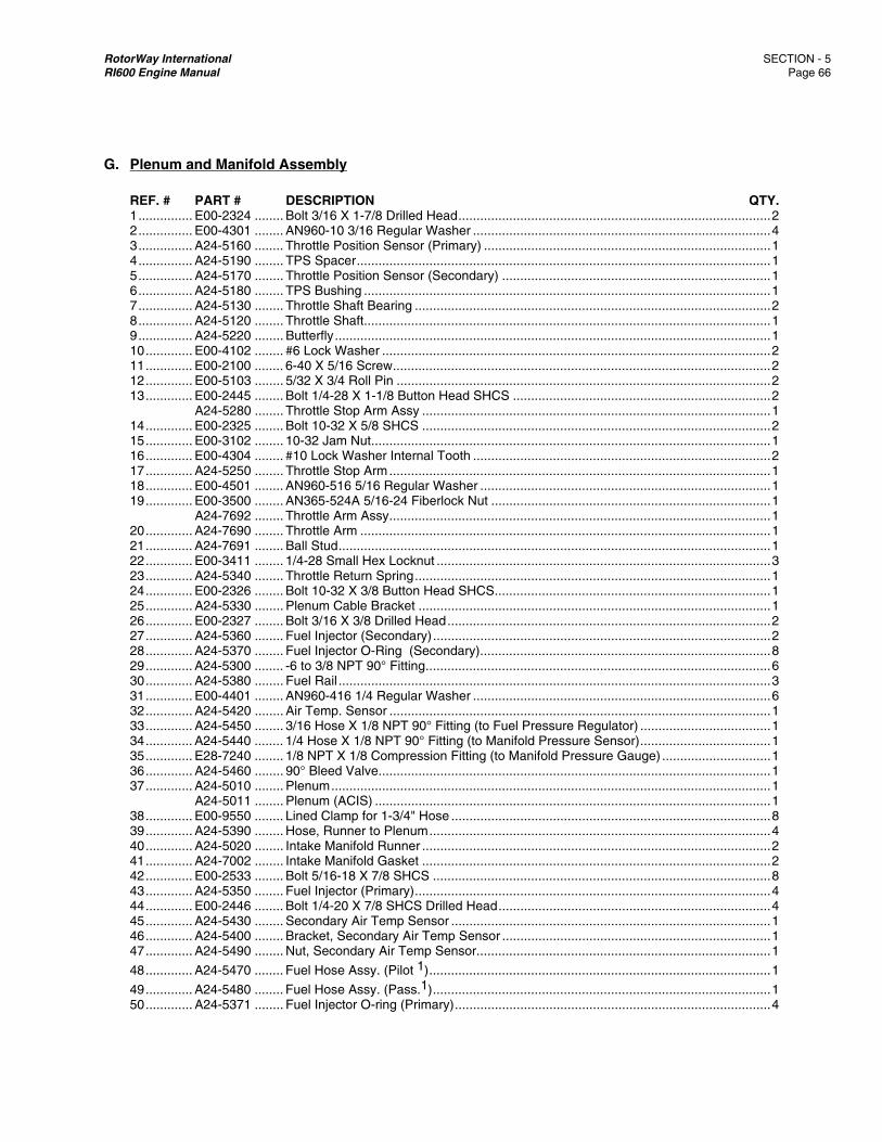
RotorWay International SECTION - 5 RI600 Engine Manual Page 66
G. Plenum and Manifold Assembly REF. # PART # DESCRIPTION QTY. 1 ............... E00-2324 ........ Bolt 3/16 X 1-7/8 Drilled Head ...................................................................................... 2 2 ............... E00-4301 ........ AN960-10 3/16 Regular Washer .................................................................................. 4 3 ............... A24-5160 ........ Throttle Position Sensor (Primary) ............................................................................... 1 4 ............... A24-5190 ........ TPS Spacer .................................................................................................................. 1 5 ............... A24-5170 ........ Throttle Position Sensor (Secondary) .......................................................................... 1 6 ............... A24-5180 ........ TPS Bushing ................................................................................................................ 1 7 ............... A24-5130 ........ Throttle Shaft Bearing .................................................................................................. 2 8 ............... A24-5120 ........ Throttle Shaft................................................................................................................ 1 9 ............... A24-5220 ........ Butterfly ........................................................................................................................ 1 10 ............. E00-4102 ........ #6 Lock Washer ........................................................................................................... 2 11 ............. E00-2100 ........ 6-40 X 5/16 Screw ........................................................................................................ 2 12 ............. E00-5103 ........ 5/32 X 3/4 Roll Pin ....................................................................................................... 2 13 ............. E00-2445 ........ Bolt 1/4-28 X 1-1/8 Button Head SHCS ....................................................................... 2 A24-5280 ........ Throttle Stop Arm Assy ................................................................................................ 1 14 ............. E00-2325 ........ Bolt 10-32 X 5/8 SHCS ................................................................................................ 2 15 ............. E00-3102 ........ 10-32 Jam Nut.............................................................................................................. 1 16 ............. E00-4304 ........ #10 Lock Washer Internal Tooth .................................................................................. 2 17 ............. A24-5250 ........ Throttle Stop Arm ......................................................................................................... 1 18 ............. E00-4501 ........ AN960-516 5/16 Regular Washer ................................................................................ 1 19 ............. E00-3500 ........ AN365-524A 5/16-24 Fiberlock Nut ............................................................................. 1 A24-7692 ........ Throttle Arm Assy ......................................................................................................... 1 20 ............. A24-7690 ........ Throttle Arm ................................................................................................................. 1 21 ............. A24-7691 ........ Ball Stud ....................................................................................................................... 1 22 ............. E00-3411 ........ 1/4-28 Small Hex Locknut ............................................................................................ 3 23 ............. A24-5340 ........ Throttle Return Spring .................................................................................................. 1 24 ............. E00-2326 ........ Bolt 10-32 X 3/8 Button Head SHCS ............................................................................ 1 25 ............. A24-5330 ........ Plenum Cable Bracket ................................................................................................. 1 26 ............. E00-2327 ........ Bolt 3/16 X 3/8 Drilled Head ......................................................................................... 2 27 ............. A24-5360 ........ Fuel Injector (Secondary) ............................................................................................. 2 28 ............. A24-5370 ........ Fuel Injector O-Ring (Secondary) ................................................................................ 8 29 ............. A24-5300 ........ -6 to 3/8 NPT 90° Fitting ............................................................................................... 6 30 ............. A24-5380 ........ Fuel Rail ....................................................................................................................... 3 31 ............. E00-4401 ........ AN960-416 1/4 Regular Washer .................................................................................. 6 32 ............. A24-5420 ........ Air Temp. Sensor ......................................................................................................... 1 33 ............. A24-5450 ........ 3/16 Hose X 1/8 NPT 90° Fitting (to Fuel Pressure Regulator) .................................... 1 34 ............. A24-5440 ........ 1/4 Hose X 1/8 NPT 90° Fitting (to Manifold Pressure Sensor) .................................... 1 35 ............. E28-7240 ........ 1/8 NPT X 1/8 Compression Fitting (to Manifold Pressure Gauge) .............................. 1 36 ............. A24-5460 ........ 90° Bleed Valve............................................................................................................ 1 37 ............. A24-5010 ........ Plenum ......................................................................................................................... 1 A24-5011 ........ Plenum (ACIS) ............................................................................................................. 1 38 ............. E00-9550 ........ Lined Clamp for 1-3/4" Hose ........................................................................................ 8 39 ............. A24-5390 ........ Hose, Runner to Plenum .............................................................................................. 4 40 ............. A24-5020 ........ Intake Manifold Runner ................................................................................................ 2 41 ............. A24-7002 ........ Intake Manifold Gasket ................................................................................................ 2 42 ............. E00-2533 ........ Bolt 5/16-18 X 7/8 SHCS ............................................................................................. 8 43 ............. A24-5350 ........ Fuel Injector (Primary) .................................................................................................. 4 44 ............. E00-2446 ........ Bolt 1/4-20 X 7/8 SHCS Drilled Head ........................................................................... 4 45 ............. A24-5430 ........ Secondary Air Temp Sensor ........................................................................................ 1 46 ............. A24-5400 ........ Bracket, Secondary Air Temp Sensor .......................................................................... 1 47 ............. A24-5490 ........ Nut, Secondary Air Temp Sensor ................................................................................. 1
48 ............. A24-5470 ........ Fuel Hose Assy. (Pilot 1) .............................................................................................. 1
49 ............. A24-5480 ........ Fuel Hose Assy. (Pass.1) ............................................................................................. 1 50 ............. A24-5371 ........ Fuel Injector O-ring (Primary) ....................................................................................... 4
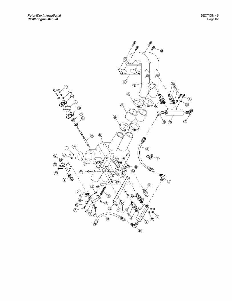
RotorWay IRI600 Engin
International ne Manual
SECTION - Page 67
5 7
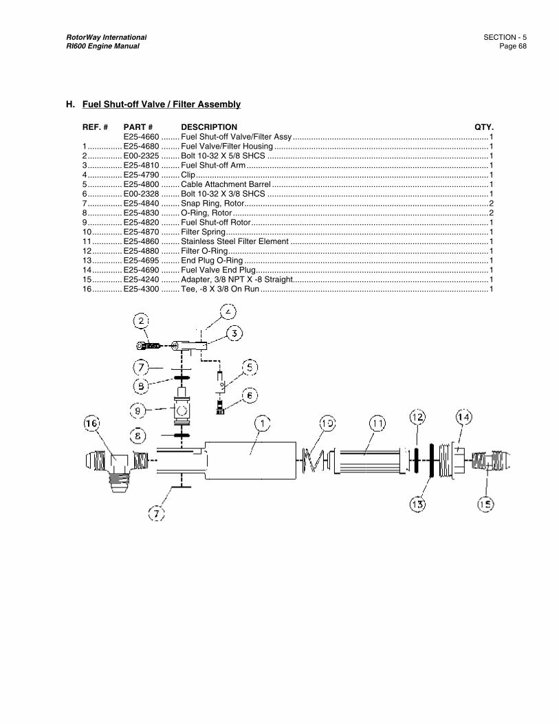
RotorWay IRI600 Engin
H. Fuel S REF. # 1 ........ 2 ........ 3 ........ 4 ........ 5 ........ 6 ........ 7 ........ 8 ........ 9 ........ 10 ...... 11 ...... 12 ...... 13 ...... 14 ...... 15 ...... 16 ......
International ne Manual
Shut-off Valv
# PART # E25-4660
........ E25-4680
........ E00-2325
........ E25-4810
........ E25-4790
........ E25-4800
........ E00-2328
........ E25-4840
........ E25-4830
........ E25-4820
........ E25-4870
........ E25-4860
........ E25-4880
........ E25-4695
........ E25-4690
........ E25-4240
........ E25-4300
ve / Filter As
DESCR0 ........ Fuel Sh0 ........ Fuel Va5 ........ Bolt 10-0 ........ Fuel Sh0 ........ Clip ......0 ........ Cable A8 ........ Bolt 10-0 ........ Snap Ri0 ........ O-Ring,0 ........ Fuel Sh0 ........ Filter Sp0 ........ Stainles0 ........ Filter O-5 ........ End Plu0 ........ Fuel Va0 ........ Adapter0 ........ Tee, -8
sembly
RIPTIONut-off Valve/Fil
alve/Filter Hous32 X 5/8 SHCSut-off Arm ..............................
Attachment Bar32 X 3/8 SHCSing, Rotor ........ Rotor .............ut-off Rotor .....pring ................ss Steel Filter E-Ring ...............
ug O-Ring ........alve End Plug ...r, 3/8 NPT X -8X 3/8 On Run .
ter Assy .........sing .................S ..................................................................rrel ..................S ................................................................................................................Element ...............................................................................
8 Straight................................
.......................
.......................
.......................
.......................
.......................
.......................
.......................
.......................
.......................
.......................
.......................
.......................
.......................
.......................
.......................
.......................
.......................
.......................
.......................
.......................
.......................
.......................
.......................
.......................
.......................
.......................
.......................
.......................
.......................
.......................
.......................
.......................
.......................
.......................
.......................
.......................
.......................
.......................
.......................
.......................
.......................
.......................
.......................
.......................
.......................
.......................
.......................
.......................
.......................
.......................
.......................
SECTION - Page 6
QTY. ........ 1 ........ 1 ........ 1 ........ 1 ........ 1 ........ 1 ........ 1 ........ 2 ........ 2 ........ 1 ........ 1 ........ 1 ........ 1 ........ 1 ........ 1 ........ 1 ........ 1
5 8
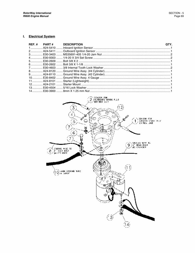
RotorWay IRI600 Engin
I. Elect REF. # 1 ........ 2 ........ 3 ........ 4 ........ 5 ........ 6 ........ 7 ........ 8 ........ 9 ........ 10 ...... 11 ...... 12 ...... 13 ...... 14 ......
International ne Manual
rical System
# PART # ........ A24-5410........ A24-5411........ E00-3403........ E00-9303........ E00-2609........ E00-2602........ E00-4603........ A24-8120........ A24-8110........ E35-8402........ A24-8101........ A24-2101........ E00-4504........ E00-3900
m
DESCR0 ........ Inboard 1 ........ Outboar3 ........ MS35693 ........ 1/4-20 X9 ........ Bolt 3/8 2 ........ Bolt 3/8 3 ........ 3/8 Inter0 ........ Ground 0 ........ Ground 2 ........ Ground 1 ........ Starter (1 ........ Starter M4 ........ 5/16 Loc0 ........ 8mm X
RIPTIONIgnition Senso
rd Ignition Sens91-405 1/4-20 JX 3/4 Set Screw
X 2 ................X 1-1/8 ..........
rnal Tooth LocWire Assy. (#4Wire Assy. (#2Wire Assy. 4 G
(Lightweight) ...Mount .............ck Washer ......1.25 mm Nut ..
or ....................sor .................Jam Nut .........w ..................................................................k Washer .......4 Cylinder) ......2 Cylinder) ......Gauge ........................................................................................................
.......................
.......................
.......................
.......................
.......................
.......................
.......................
.......................
.......................
.......................
.......................
.......................
.......................
.......................
.......................
.......................
.......................
.......................
.......................
.......................
.......................
.......................
.......................
.......................
.......................
.......................
.......................
.......................
.......................
.......................
.......................
.......................
.......................
.......................
.......................
.......................
.......................
.......................
.......................
.......................
.......................
.......................
SECTION - Page 6
QTY. ........ 1 ........ 1 ........ 2 ........ 2 ........ 1 ........ 1 ........ 2 ........ 1 ........ 1 ........ 1 ........ 1 ........ 1 ........ 1 ........ 1
5 9

RotorWay IRI600 Engin
J. Oil Sy REF. # 1 ........ 2 ........ 3 ........ 4 ........ 5 ........ 6 ........ 7 ........ 8 ........ 9 ........ 10 ...... 11 ......
International ne Manual
ystem
# PART # ........ E28-6112........ A24-2230........ A24-2240........ E36-3120........ E28-6142........ E28-6122........ E28-1201........ E28-1192........ E28-1230........ E28-1180........ E38-6660
DESCR2 ........ Oil Hose0 ........ 90° Fitti0 ........ 45° Fitti0 ........ Oil Pres2 ........ Oil Hose2 ........ Oil Hose1 ........ Oil Brea2 ........ Valve C0 ........ Main Oi0 ........ 3/8 NPT0 ........ 1/2” X 3
RIPTIONe, Sump to Oil ng ...................ng (Pump Outl
ssure Sender ...e, Oil Pump to e, Filter to Engather Cap With
Cover Drain Hosl Drain Hose ...
T Brass Plug ....3/8 NPT Hose B
Pump ...................................let) .........................................Filter ..............ine .................Dipstick .........
se .................................................................Barb (ACIS) ....
.......................
.......................
.......................
.......................
.......................
.......................
.......................
.......................
.......................
.......................
.......................
.......................
.......................
.......................
.......................
.......................
.......................
.......................
.......................
.......................
.......................
.......................
.......................
.......................
.......................
.......................
.......................
.......................
.......................
.......................
.......................
.......................
.......................
SECTION - Page 70
QTY. ........ 1 ........ 2 ........ 1 ........ 1 ........ 1 ........ 1 ........ 1 ........ 2 ........ 1 ........ 2 ........ 2
5 0
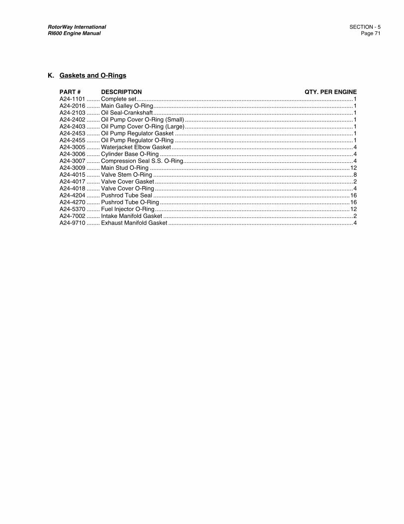
RotorWay International SECTION - 5 RI600 Engine Manual Page 71
K. Gaskets and O-Rings PART # DESCRIPTION QTY. PER ENGINE A24-1101 ........ Complete set .................................................................................................................................. 1 A24-2016 ........ Main Galley O-Ring ........................................................................................................................ 1 A24-2103 ........ Oil Seal-Crankshaft ........................................................................................................................ 1 A24-2402 ........ Oil Pump Cover O-Ring (Small) ..................................................................................................... 1 A24-2403 ........ Oil Pump Cover O-Ring (Large) ..................................................................................................... 1 A24-2453 ........ Oil Pump Regulator Gasket ........................................................................................................... 1 A24-2455 ........ Oil Pump Regulator O-Ring ........................................................................................................... 1 A24-3005 ........ Waterjacket Elbow Gasket ............................................................................................................. 4 A24-3006 ........ Cylinder Base O-Ring .................................................................................................................... 4 A24-3007 ........ Compression Seal S.S. O-Ring ...................................................................................................... 4 A24-3009 ........ Main Stud O-Ring ........................................................................................................................ 12 A24-4015 ........ Valve Stem O-Ring ........................................................................................................................ 8 A24-4017 ........ Valve Cover Gasket ....................................................................................................................... 2 A24-4018 ........ Valve Cover O-Ring ....................................................................................................................... 4 A24-4204 ........ Pushrod Tube Seal ...................................................................................................................... 16 A24-4270 ........ Pushrod Tube O-Ring .................................................................................................................. 16 A24-5370 ........ Fuel Injector O-Ring ..................................................................................................................... 12 A24-7002 ........ Intake Manifold Gasket .................................................................................................................. 2 A24-9710 ........ Exhaust Manifold Gasket ............................................................................................................... 4
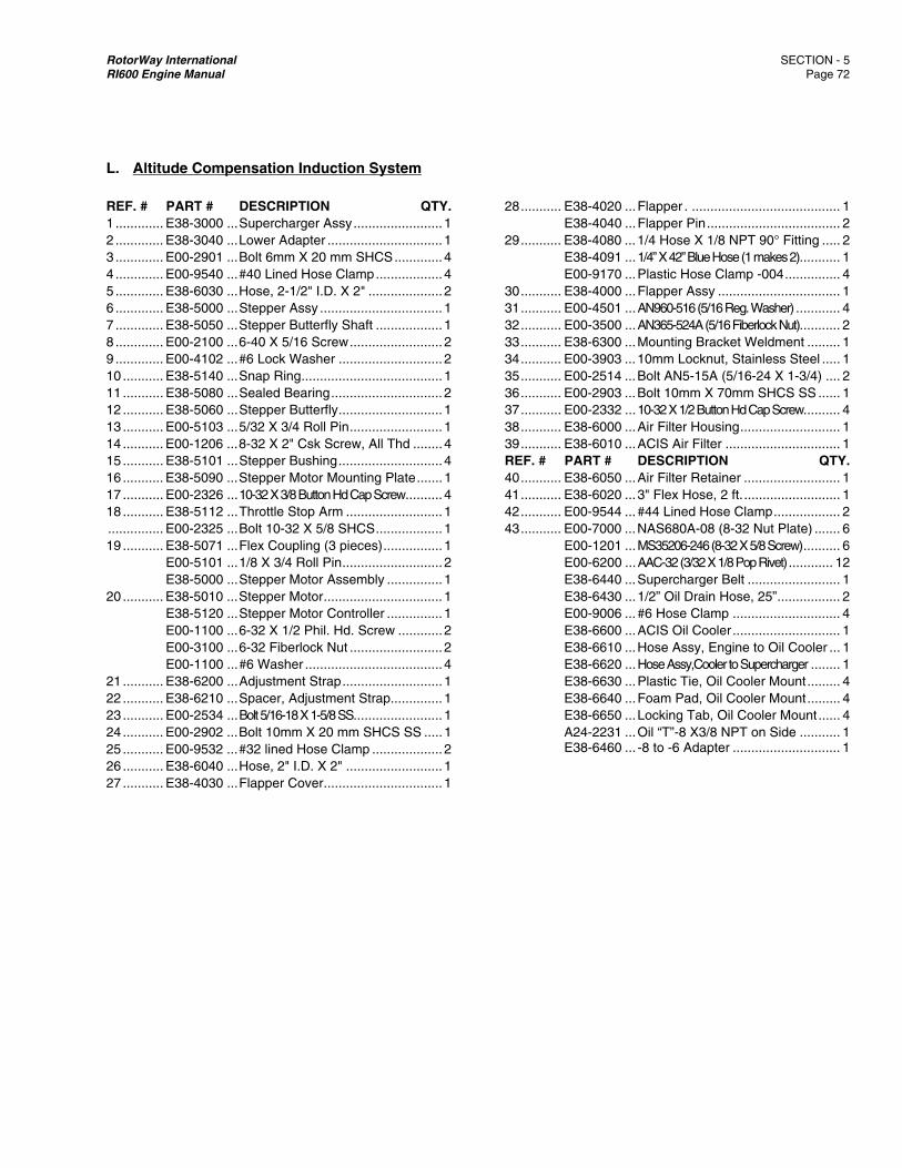
RotorWay International SECTION - 5 RI600 Engine Manual Page 72
L. Altitude Compensation Induction System
REF. # PART # DESCRIPTION QTY. 1 ............. E38-3000 ... Supercharger Assy ........................ 1 2 ............. E38-3040 ... Lower Adapter ............................... 1 3 ............. E00-2901 ... Bolt 6mm X 20 mm SHCS ............. 4 4 ............. E00-9540 ... #40 Lined Hose Clamp .................. 4 5 ............. E38-6030 ... Hose, 2-1/2" I.D. X 2" .................... 2 6 ............. E38-5000 ... Stepper Assy ................................. 1 7 ............. E38-5050 ... Stepper Butterfly Shaft .................. 1 8 ............. E00-2100 ... 6-40 X 5/16 Screw ......................... 2 9 ............. E00-4102 ... #6 Lock Washer ............................ 2 10 ........... E38-5140 ... Snap Ring ...................................... 1 11 ........... E38-5080 ... Sealed Bearing .............................. 2 12 ........... E38-5060 ... Stepper Butterfly ............................ 1 13 ........... E00-5103 ... 5/32 X 3/4 Roll Pin ......................... 1 14 ........... E00-1206 ... 8-32 X 2" Csk Screw, All Thd ........ 4 15 ........... E38-5101 ... Stepper Bushing ............................ 4 16 ........... E38-5090 ... Stepper Motor Mounting Plate ....... 1 17 ........... E00-2326 ... 10-32 X 3/8 Button Hd Cap Screw .......... 4 18 ........... E38-5112 ... Throttle Stop Arm .......................... 1 ............... E00-2325 ... Bolt 10-32 X 5/8 SHCS .................. 1 19 ........... E38-5071 ... Flex Coupling (3 pieces) ................ 1 E00-5101 ... 1/8 X 3/4 Roll Pin ........................... 2 E38-5000 ... Stepper Motor Assembly ............... 1 20 ........... E38-5010 ... Stepper Motor ................................ 1 E38-5120 ... Stepper Motor Controller ............... 1 E00-1100 ... 6-32 X 1/2 Phil. Hd. Screw ............ 2 E00-3100 ... 6-32 Fiberlock Nut ......................... 2 E00-1100 ... #6 Washer ..................................... 4 21 ........... E38-6200 ... Adjustment Strap ........................... 1 22 ........... E38-6210 ... Spacer, Adjustment Strap .............. 1 23 ........... E00-2534 ... Bolt 5/16-18 X 1-5/8 SS ........................ 1 24 ........... E00-2902 ... Bolt 10mm X 20 mm SHCS SS ..... 1 25 ........... E00-9532 ... #32 lined Hose Clamp ................... 2 26 ........... E38-6040 ... Hose, 2" I.D. X 2" .......................... 1 27 ........... E38-4030 ... Flapper Cover ................................ 1
28 ........... E38-4020 ... Flapper . ........................................ 1 E38-4040 ... Flapper Pin .................................... 2 29 ........... E38-4080 ... 1/4 Hose X 1/8 NPT 90° Fitting ..... 2 E38-4091 ... 1/4” X 42” Blue Hose (1 makes 2) ........... 1 E00-9170 ... Plastic Hose Clamp -004 ............... 4 30 ........... E38-4000 ... Flapper Assy ................................. 1 31 ........... E00-4501 ... AN960-516 (5/16 Reg. Washer) ............ 4 32 ........... E00-3500 ... AN365-524A (5/16 Fiberlock Nut) ........... 2 33 ........... E38-6300 ... Mounting Bracket Weldment ......... 1 34 ........... E00-3903 ... 10mm Locknut, Stainless Steel ..... 1 35 ........... E00-2514 ... Bolt AN5-15A (5/16-24 X 1-3/4) .... 2 36 ........... E00-2903 ... Bolt 10mm X 70mm SHCS SS ...... 1 37 ........... E00-2332 ... 10-32 X 1/2 Button Hd Cap Screw.......... 4 38 ........... E38-6000 ... Air Filter Housing ........................... 1 39 ........... E38-6010 ... ACIS Air Filter ............................... 1 REF. # PART # DESCRIPTION QTY. 40 ........... E38-6050 ... Air Filter Retainer .......................... 1 41 ........... E38-6020 ... 3" Flex Hose, 2 ft. .......................... 1 42 ........... E00-9544 ... #44 Lined Hose Clamp .................. 2 43 ........... E00-7000 ... NAS680A-08 (8-32 Nut Plate) ....... 6 E00-1201 ... MS35206-246 (8-32 X 5/8 Screw) .......... 6 E00-6200 ... AAC-32 (3/32 X 1/8 Pop Rivet) ............ 12 E38-6440 ... Supercharger Belt ......................... 1 E38-6430 ... 1/2” Oil Drain Hose, 25” ................. 2 E00-9006 ... #6 Hose Clamp ............................. 4 E38-6600 ... ACIS Oil Cooler ............................. 1 E38-6610 ... Hose Assy, Engine to Oil Cooler ... 1 E38-6620 ... Hose Assy,Cooler to Supercharger ........ 1 E38-6630 ... Plastic Tie, Oil Cooler Mount ......... 4 E38-6640 ... Foam Pad, Oil Cooler Mount ......... 4 E38-6650 ... Locking Tab, Oil Cooler Mount ...... 4 A24-2231 ... Oil “T”-8 X3/8 NPT on Side ........... 1 E38-6460 ... -8 to -6 Adapter ............................. 1
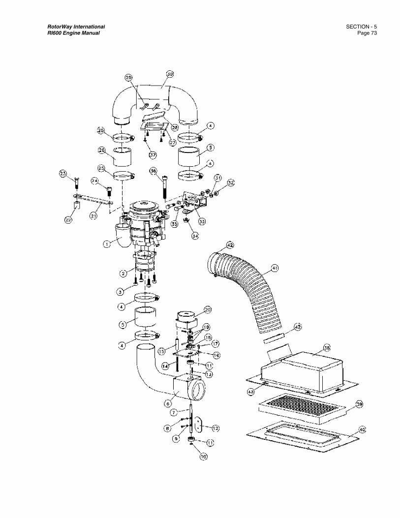
RotorWay IRI600 Engin
International ne Manual
SECTION - Page 73
5 3
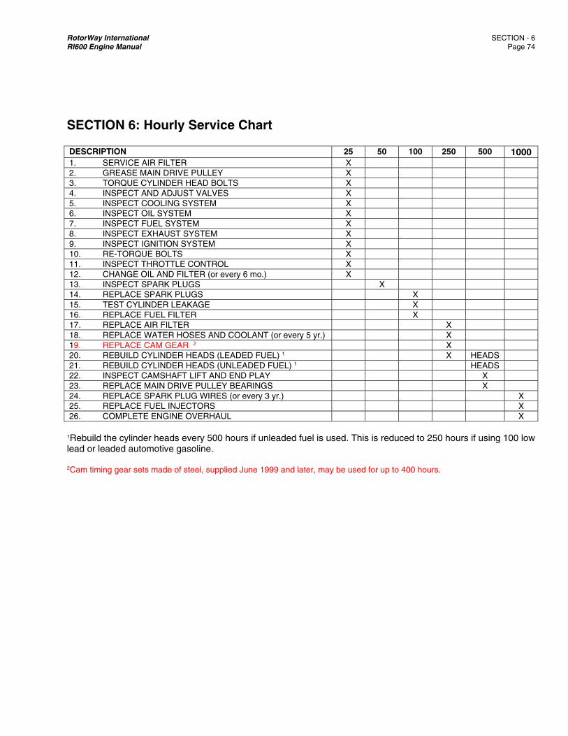
RotorWay International SECTION - 6 RI600 Engine Manual Page 74
SECTION 6: Hourly Service Chart DESCRIPTION 25 50 100 250 500 10001. SERVICE AIR FILTER X 2. GREASE MAIN DRIVE PULLEY X 3. TORQUE CYLINDER HEAD BOLTS X 4. INSPECT AND ADJUST VALVES X 5. INSPECT COOLING SYSTEM X 6. INSPECT OIL SYSTEM X 7. INSPECT FUEL SYSTEM X 8. INSPECT EXHAUST SYSTEM X 9. INSPECT IGNITION SYSTEM X 10. RE-TORQUE BOLTS X 11. INSPECT THROTTLE CONTROL X 12. CHANGE OIL AND FILTER (or every 6 mo.) X 13. INSPECT SPARK PLUGS X 14. REPLACE SPARK PLUGS X 15. TEST CYLINDER LEAKAGE X 16. REPLACE FUEL FILTER X 17. REPLACE AIR FILTER X 18. REPLACE WATER HOSES AND COOLANT (or every 5 yr.) X 19. REPLACE CAM GEAR 2 X 20. REBUILD CYLINDER HEADS (LEADED FUEL) 1 X HEADS 21. REBUILD CYLINDER HEADS (UNLEADED FUEL) 1 HEADS 22. INSPECT CAMSHAFT LIFT AND END PLAY X 23. REPLACE MAIN DRIVE PULLEY BEARINGS X 24. REPLACE SPARK PLUG WIRES (or every 3 yr.) X 25. REPLACE FUEL INJECTORS X 26. COMPLETE ENGINE OVERHAUL X 1Rebuild the cylinder heads every 500 hours if unleaded fuel is used. This is reduced to 250 hours if using 100 low lead or leaded automotive gasoline. 2Cam timing gear sets made of steel, supplied June 1999 and later, may be used for up to 400 hours.