Rhino-Rack - Fitting Instructions - R1913 RTS525 Ford...
6
Page 1 of 6 RTS525 Ford Ranger PX USA - Two Cross Bar Track Mount System Important Information Important: Please read these instructions carefully prior to installation. Please refer to your fitting instruction to ensure that the roof racks are installed in the correct locations. Check the contents of kit before commencing fitment and report any discrepancies Maximum carrying capacity: On Road Cargo Allowance Unsealed Road Cargo Allowance Roof Allowance Rack Weight 95kg / 209lb 75kg / 165lb 100kg / 220lb 5kg / 11lb Unsealed Road: Any driven path taken that is not on sealed (tarred/ bitumen) and maintained road Roof Allowance: Total permissible weight attached to the roof of the car. This is inclusive of the weight of the roof rack system Cargo Allowance: Total permissible weight allowed on top, and attached to roof racks whilst the vehicle is in motion Please refer to your vehicle manufacturers handbook for maximum carrying capacity. Always use the lower of the two figures. Load must be evenly distributed over the entire system. Weight of roof rack accessories is to be included in cargo allowance. Torque settings Unless stated otherwise in these instructions, all fasteners should be set to the following torque settings - M6: 4-5Nm (3-4lbs/ft), M8: 8-10Nm (6-7.5lbs/ft) and M10: 16-18Nm (12-13lbs/ft). Warning: • Check Part No. and/ or Kit is correct for use with your vehicle • Do not attempt to fit the rack system to your vehicle unless you fully understand these fitting instructions. Please direct any questions regarding fitting to the dealer from where the roof racks were purchased. • Use only non-stretch fastening ropes or straps. • The handling characteristics of the vehicle changes when you transport a load on the roof. For safety reasons we recommend you exercise extreme care when transporting wind-resistant loads. Special consideration must be taken into account when cornering and braking. • Although the system is tested and approved to AS1235-2000 / ISO 11154, off-road conditions can be much more rigorous. Extreme care must be taken in off road conditions Recommendations: It is essential that all bolt connections be checked after driving a short distance when you first install your roof racks. Bolt connections should be checked again at regular intervals (once a week is enough, depending on road conditions, usage, loads and distances travelled). You should also check the roof racks each time they are re-fitted. Always make sure to fasten your load securely. Please also ensure that all loads are evenly distributed and that the centre of gravity is kept as low as possible and must be entirely contained within the extents of the roof racks. Note for Dealers and Fitters: It is your responsibility to ensure these fitting instructions are given to the end user or client Rhino-Rack, 22 Hanson St, Eastern Creek NSW 2766, Australia Document No: R1913 (02) 8846 1900 Issue No: 2 rhinorack.com.au Issue Date: 09/05/2019 These instructions remain the property of Rhino-Rack Australia Pty. Ltd. and may not be used or changed for any other purpose than intended. Be sure to check Rhino-Rack website to ascertain if you have the latest version of instructions.
Transcript of Rhino-Rack - Fitting Instructions - R1913 RTS525 Ford...

Page 1 of 6
RTS525 Ford Ranger PX USA - Two Cross Bar Track Mount System
Important Information
Important: Please read these instructions carefully prior to installation. Please refer to your fi tting instruction to ensure that the roof racks are installed in the correct locations. Check the contents of kit before commencing fi tment and report any discrepancies
Maximum carrying capacity:
On Road Cargo Allowance
Unsealed Road Cargo Allowance Roof Allowance Rack Weight
95kg / 209lb 75kg / 165lb 100kg / 220lb 5kg / 11lb
Unsealed Road: Any driven path taken that is not on sealed (tarred/ bitumen) and maintained roadRoof Allowance: Total permissible weight attached to the roof of the car. This is inclusive of the weight of the roof rack systemCargo Allowance: Total permissible weight allowed on top, and attached to roof racks whilst the vehicle is in motion Please refer to your vehicle manufacturers handbook for maximum carrying capacity. Always use the lower of the two fi gures. Load must be evenly distributed over the entire system. Weight of roof rack accessories is to be included in cargo allowance.Torque settings Unless stated otherwise in these instructions, all fasteners should be set to the following torque settings -M6: 4-5Nm (3-4lbs/ft), M8: 8-10Nm (6-7.5lbs/ft) and M10: 16-18Nm (12-13lbs/ft).Warning: • Check Part No. and/ or Kit is correct for use with your vehicle
• Do not attempt to fi t the rack system to your vehicle unless you fully understand these fi tting instructions. Please direct any questions regarding fi tting to the dealer from where the roof racks were purchased.
• Use only non-stretch fastening ropes or straps. • The handling characteristics of the vehicle changes when you transport a load on the roof. For safety reasons we recommend you
exercise extreme care when transporting wind-resistant loads. Special consideration must be taken into account when cornering and braking.
• Although the system is tested and approved to AS1235-2000 / ISO 11154, off -road conditions can be much more rigorous. Extreme care must be taken in off road conditions
Recommendations: It is essential that all bolt connections be checked after driving a short distance when you fi rst install your roof racks. Bolt connections should be checked again at regular intervals (once a week is enough, depending on road conditions, usage, loads and distances travelled). You should also check the roof racks each time they are re-fi tted. Always make sure to fasten your load securely. Please also ensure that all loads are evenly distributed and that the centre of gravity is kept as low as possible and must be entirely contained within the extents of the roof racks.
Note for Dealers and Fitters: It is your responsibility to ensure these fi tting instructions are given to the end user or clientRhino-Rack, 22 Hanson St, Eastern CreekNSW 2766, Australia Document No: R1913(02) 8846 1900 Issue No: 2rhinorack.com.au Issue Date: 09/05/2019These instructions remain the property of Rhino-Rack Australia Pty. Ltd. and may not be used or changed for any other purpose than intended.
Be sure to check Rhino-Rack website to ascertain if you have
the latest version of instructions.
rod.renkin
Controlled
Page 2 of 6
4
3
2
1
5
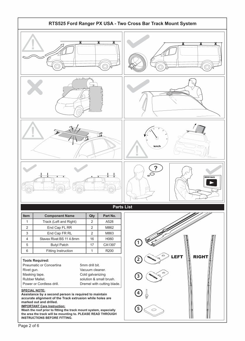
Item Component Name Qty Part No.1 Track (Left and Right) 2 A5282 End Cap FL RR 2 M8623 End Cap FR RL 2 M8634 Stavex Rivet BS 11 4.8mm 16 H0605 Butyl Patch 17 CA13976 Fitting Instruction 1 R200
LEFT RIGHT
RTS525 Ford Ranger PX USA - Two Cross Bar Track Mount System
Parts List
Tools Required:Pneumatic or ConcertinaRivet gun.Masking tape.Rubber Mallet.Power or Cordless drill.
5mm drill bit.Vacuum cleaner.Cold galvanizingsolution & small brush.Dremel with cutting blade.
SPECIAL NOTE:Assistance by a second person is required to maintain accurate alignment of the Track extrusion while holes are marked out and drilled.IMPORTANT Care Instruction:Wash the roof prior to fi tting the track mount system, especially the area the track will be mounting to. PLEASE READ THROUGH INSTRUCTIONS BEFORE FITTING.
km/h
?
!
!!

Page 3 of 6
NOTE: WE RECOMMEND THAT YOU COMPLETELY INSTALL ONE TRACK AT A TIME.
1
2
Short edge facesOUTSIDE of vehicle.
Short edge facesOUTSIDE of vehicle.
TOP VIEW
Front of car
REAR of car
RIGHT Track
LEFT Track
LEFT Track
RIGHT Track
Rectangular cut out REAR
The track extrusions are Left and Right handed. Each track has 2 circular cut outs at one end, this denotes the FRONT of the vehicle. The single large rectangular cut out denotes the REAR.
Align the REAR of the track as shown. Create a reference here with a marker.
2 circular cut outs FRONT !
Extra care when
drilling this hole
due to airbag
location
Approximately 7 1/4” (185mm) from the REAR of car
Ditch mould tooling line.
1 9/16” (40mm)
RTS525 Ford Ranger PX USA - Two Cross Bar Track Mount System
Fitting Instructions
Page 4 of 6
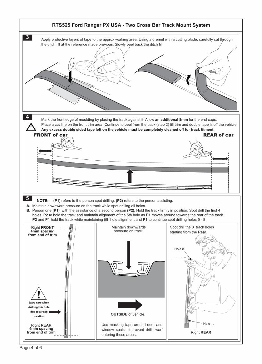
A. Maintain downward pressure on the track while spot drilling all holes.B. Person one (P1), with the assistance of a second person (P2). Hold the track fi rmly in position. Spot drill the fi rst 4 holes. P2 to hold the track and maintain alignment of the 5th hole as P1 moves around towards the rear of the track. P2 and P1 hold the track while maintaining 5th hole alignment and P1 to continue spot drilling holes 5 - 8
5 NOTE: (P1) refers to the person spot drilling. (P2) refers to the person assisting.
Spot drill the 8 track holes starting from the Rear.
Maintain downwards pressure on track.
OUTSIDE of vehicle.
Use masking tape around door and window seals to prevent drill swarf entering these areas.
Hole 8.
Hole 1.
4mm spacingfrom end of trim
4mm spacingfrom end of trim
Right REAR
Right FRONT
Right REAR
4 Mark the front edge of moulding by placing the track against it. Allow an additional 8mm for the end caps.Place a cut line on the front trim area. Continue to peel from the back (step 2) till trim and double tape is off the vehicle. Any excess double sided tape left on the vehicle must be completely cleaned off for track fi tment
REAR of carFRONT of car!
3 Apply protective layers of tape to the approx working area. Using a dremel with a cutting blade, carefully cut through the ditch fi ll at the reference made previous. Slowly peel back the ditch fi ll.
!Extra care when
drilling this hole
due to airbag
location
RTS525 Ford Ranger PX USA - Two Cross Bar Track Mount System

Page 5 of 6
9 Peel the white backing strip off the track foam tape.
8b 1:Remove the backing tape from the ButylPatches. 2:Place over holes drilled. Once in place remove the rest of the protective tape from the top of the patches.
1.
8a Apply a liberal amount of cold galvanizing solution to the inside and surrounds of all holes. Allow cold galvanizing solution to touch dry, ten minutes or so.
6 All 8 holes can now be drilled through. A drill stop must be used to prevent drilling through the hood lining on the inside. Make sure that when drilling you hold the drill perpendicular to the roof angle. The roof skin is approx. 2-3mm thick.
90° Drill stop.RDS sold as separate
7 Use a vacuum to remove swarf to eliminate scratching. Wipe clean the installation area of the roof.
ALWAYS vacuum swarf. NEVER blow swarf away with an air gun as it will cause rust
!
RTS525 Ford Ranger PX USA - Two Cross Bar Track Mount System

Page 6 of 6
10Insert the end caps at each end. Ensure that the profi le of the end cap matches the ends as shown
11
End cap.
End cap.
Line up and place all 8 rivets in their respective holes. Pay extra attention to the 5th hole (from the front) where the air bag module resides. With the assistance of a second person to maintain track alignment start rivet-ing from the centre rivet. Follow the numerical riveting order as shown below. Holes 6 and 8 will have the end caps.
1.2. 3.4.
7. 8.
6. 5.
M862 - Front Left and Rear RightM863 - Front Right and Rear Left
REAR of car
FRONT of car
! Airbag location here
RTS525 Ford Ranger PX USA - Two Cross Bar Track Mount System