Rexroth System setup and access
31
Rexroth System setup and access management in the BOS 5000 Confidential Mobile Hydraulics Service Automation Pneumatics Linear Motion Assembly Technologies Electric Drives and Controls Industrial Hydraulics Technical Information 1070 087 054 Edition 03
Transcript of Rexroth System setup and access

Rexroth System setup and access management in the BOS 5000
Confidential
MobileHydraulics
ServiceAutomationPneumatics
Linear MotionAssembly Technologies
Electric Drivesand Controls
IndustrialHydraulics
Technical Information
1070 087 054 Edition 03

II Electric Drivesand Controls
Bosch Rexroth AG PSS 5000 - System setup 1070 087 054 / 03
Rexroth System setup and access management in the BOS 5000
Confidential
Technical Information
DOK-PS5000-Systeminfo*-PA03-EN-P
The present manual informs about:
D the password protection of the BOS-5000 user interface, andD the user levels.
Description ReleaseDate
Notes
DOK-PS5000-Systeminfo*-PA03-EN-P 08.2003
E Bosch Rexroth AG, 1998 - 2003
Copying this document, giving it to others and the use orcommunication of the contents thereof without express authority areforbidden. Offenders are liable for the payment of damages. All rightsare reserved in the event of the grant of a patent or the registrationof a utility model or design (DIN 34-1).
The specified data is for product description purposes only andmay not be deemed to be guaranteed unless expressly confirmedin the contract. All rights are reserved with respect to the contentsof this documentation and the availability of the product.
Bosch Rexroth AGPostfach 11 62D-64701 ErbachBerliner Straße 25D-64711 ErbachTel.: +49 (0) 60 62/78-0Fax: +49 (0) 60 62/78-4 28Abt.: BRC - WS/VTR
Title
Type of Documentation
Document Type Code
Purpose of Documentation
Record of Revisions
Copyright
Validity
Published by

Electric Drivesand Controls
IIIBosch Rexroth AGPSS 5000 - System setup1070 087 054 / 03
Contents
ContentsPage
1 Safety instructions and notes for the reader 1-11.1 Typographic conventions 1-3. . . . . . . . . . . . . . . . . . . . . . . . . . . . . 1.2 Proper use 1-3. . . . . . . . . . . . . . . . . . . . . . . . . . . . . . . . . . . . . . . . . 1.3 Not permitted for persons with cardiac pacemakers 1-4. . . . . . 1.4 Qualified personnel 1-5. . . . . . . . . . . . . . . . . . . . . . . . . . . . . . . . . .
2 General 2-1. . . . . . . . . . . . . . . . . . . . . . . . . . . . . . . . . 2.1 Adjusting the access management 2-3. . . . . . . . . . . . . . . . . . . .
3 System menu BOS-5000 3-1. . . . . . . . . . . . . . . . . . 3.1 Windows Setup 3-2. . . . . . . . . . . . . . . . . . . . . . . . . . . . . . . . . . . . . 3.2 Access management 3-2. . . . . . . . . . . . . . . . . . . . . . . . . . . . . . . . 3.3 Read user file 3-5. . . . . . . . . . . . . . . . . . . . . . . . . . . . . . . . . . . . . . . 3.4 Read mask file 3-6. . . . . . . . . . . . . . . . . . . . . . . . . . . . . . . . . . . . . . 3.5 Creating a user disk 3-7. . . . . . . . . . . . . . . . . . . . . . . . . . . . . . . . . 3.6 Protocol memory setup 3-7. . . . . . . . . . . . . . . . . . . . . . . . . . . . . . 3.7 BOS-5000 Setup 3-8. . . . . . . . . . . . . . . . . . . . . . . . . . . . . . . . . . . .
4 Order data 4-1. . . . . . . . . . . . . . . . . . . . . . . . . . . . . . .
A Annex A-1. . . . . . . . . . . . . . . . . . . . . . . . . . . . . . . . . . . A.1 Index A-1. . . . . . . . . . . . . . . . . . . . . . . . . . . . . . . . . . . . . . . . . . . . . .

IV Electric Drivesand Controls
Bosch Rexroth AG PSS 5000 - System setup 1070 087 054 / 03
Contents
Notes:

Electric Drivesand Controls
1-1Bosch Rexroth AGPSS 5000 - System setup1070 087 054 / 03
Safety instructions and notes for the reader
1 Safety instructions and notes for the reader
Read this document before working for the first time with the systemsetup and the access management of the BOS-5000 software.Store this manual in a place to which the system administrator has ac-cess at any time. The information contained in this manual should onlybe available to the system administrators.
The products described here were developed, manufactured, testedand documented in compliance with the safety standards of the EU Ma-chinery Directive.
Nevertheless, there still is some residual risk!
The present documentation describes the- Access management (access control)- System setup
in the BOS-5000 software.
There is a certain hierarchy of warnings in this manual. The warningsare printed in bold letters and marked by a warning sign at the margin ofthe page to attract the reader�s attention.
The hierarchy of warnings is as follows:1. WARNING2. ATTENTION3. NOTE
WARNING!
The term WARNING will be used wherever danger is imminent.The possible consequences may be death or severe injury (personal in-jury).
ATTENTION!
The term ATTENTION will be used wherever a dangerous situation ispossible.The possible consequences include death, severe or light injury (per-sonal injury), damage to property (destruction of modules) or environ-mental hazards.In any case, you will lose your warranty in the event of non-compliancewith/non-observation of these warnings.
!
!

1-2 Electric Drivesand Controls
Bosch Rexroth AG PSS 5000 - System setup 1070 087 054 / 03
Safety instructions and notes for the reader
NOTE
The term NOTE will be used for making recommendations on the use.Here, you will find additional information, recommendations, notes, andtips.Non-compliance with these recommendations may result in damage toproperty, e.g., to the machine or the workpiece.

Electric Drivesand Controls
1-3Bosch Rexroth AGPSS 5000 - System setup1070 087 054 / 03
Safety instructions and notes for the reader
1.1 Typographic conventions
General listing - Example: - The message isdisplayed onthe screen.
Activities D Example: D Insert floppy disk,D Read value.
Screen displays, Italics Example: Battery emptymessages, displays Dressing request.
(Welding) parameters [in brackets] Example: [Weld time],[Schedule].
Interface signals, keys,<Key> Example: Press <F8>Command buttons
Inputs: Values, texts CAPITAL LETTERS
NOTEPlease note: Black bars at the margin of the page indicate that changeshave been made compared to the previous edition.The present documentation has been completely revised.
1.2 Proper use
The present manual contains information concerning the proper use ofthe system setup and the access management (access control) for pro-gramming and operating weld timers with the BOS-5000 software.
In conjunction with the prescribed welding equipment, weld timers servefor:
- Resistance welding of metals- in industrial environments pursuant to DIN EN 50082-2 and
DIN EN 50081-2 relating to electromagnetic compatibility
Any other application is deemed improper use!
ATTENTION!
The consequences of an improper use include personal damages of theuser or of third parties as well as damages to property � the technicalequipment, the workpiece to be processed, or environmental hazards.Therefore, you should only use our products for their intended purpose!
!

1-4 Electric Drivesand Controls
Bosch Rexroth AG PSS 5000 - System setup 1070 087 054 / 03
Safety instructions and notes for the reader
1.3 Not permitted for persons with cardiac pacemakers
WARNING for persons with cardiac pacemakers!
Warning signs should be posted for protecting persons with cardiacpacemakers because the function of these devices may be disturbed(impulse failure, total failure) and a negative influence on the pacemakerprogramming or even a total program destruction may occur!!!
We recommend posting a warning of the type shown below at all en-trances to factory halls containing resistance welding equipment:
No entry for persons with cardiacpacemakers!
Danger!DIN 40023
!

Electric Drivesand Controls
1-5Bosch Rexroth AGPSS 5000 - System setup1070 087 054 / 03
Safety instructions and notes for the reader
1.4 Qualified personnel
This manual is designed for specifically trained system administrators orskilled welding engineers with special knowledge of the welding technol-ogy.
They require profound knowledge of:- Weld timers (WT)
The term qualified personnel refers to
- engineering personnel familiar with the safety standards of theelectrical and automation technology
- commissioning personnel entitled to commission, earth and labelelectrical circuits and equipment/systems in compliance with thestandards of safety technology.
WARNING!
An exception are persons with cardiac pacemakers! Due to the strong magnetic fields arising from resistance welding, thefunction of cardiac pacemakers may be disturbed. This may cause thedeath or considerable health damages to the persons concerned!Therefore, these persons should avoid the welding system.
Please note our comprehensive range of training courses. Our trainingcenter will be pleased to provide you with further information, telephone+49 (0) 6062 / 78 258.
!

1-6 Electric Drivesand Controls
Bosch Rexroth AG PSS 5000 - System setup 1070 087 054 / 03
Safety instructions and notes for the reader
Notes:

Electric Drivesand Controls
2-1Bosch Rexroth AGPSS 5000 - System setup1070 087 054 / 03
General
2 GeneralThe installation of the BOS-5000 software is performed with default set-tings which may be adjusted to the internal requirements by the systemadministrator or the specialized welding engineer.
The first login is carried out by:
- User group DEMO
- User password DEMO
The following adjustments should be made after installation:
System setup
- How does the BOS-5000 software work, e.g., which communica-tion channel (COM interface, PROFIBUS or INTERBUS) is usedto link the programming terminal to the timer?
System administrator
BOS-5000
Language of the BOS-5000 user interface
Directoriescontaining user data
Protocols
Communication channelTimer type and selection
Login: User group User password
Selection ofFault displays

2-2 Electric Drivesand Controls
Bosch Rexroth AG PSS 5000 - System setup 1070 087 054 / 03
General
Access management
- Each user group is assigned a unique name and user level, refer to3.2 and 3.3.
- Each mask displayed has an alterable read and write level.
- A screen mask will be displayed whenever the user level is higherthan or equal to the read level for this screen.
- Values can be changed in a screen mask if the user level is higherthan or equal to the write level for this screen.
- The user name and password can be saved on a floppy disk to pro-vide for logging in without keyboard entry, refer to 3.
User group e.g. Maintenance personnel
(MP)
User group e.g. Line supervisor
(LS)
User group e.g. Operator
(OP)Systemadministrator
User level
5
4
2

Electric Drivesand Controls
2-3Bosch Rexroth AGPSS 5000 - System setup1070 087 054 / 03
General
2.1 Adjusting the access management
The access privileges for the various user groups can be assigned afterthe installation of the BOS-5000 software.
Procedure
- New Login with system disk:D Start window BOS-5000 - System - New Login or <F12>
- Define user groups, user passwords and user levelsD Start window BOS-5000 - System - Access management, refer to
section 3.2or
D Read and adjust user file, refer to section 3.3
D Read mask file (access rights have also been defined without�Read mask file�), refer to section 3.4
- New Login with lowest user level:D Start window BOS-5000 - System - New Login or <F12>
- Inform user groups of user passwords together with the informa-tion that user passwords can be individually changed by the usergroups.
- Changing the user password by the user group:D Start window BOS-5000 - System - Password edit
NOTE
User passwords that have been changed later on by the user group will render apreviously generated user disk invalid.
- Create user floppies containing the user group and user pass-word, refer to section 3.5.

2-4 Electric Drivesand Controls
Bosch Rexroth AG PSS 5000 - System setup 1070 087 054 / 03
General
Notes:

Electric Drivesand Controls
3-1Bosch Rexroth AGPSS 5000 - System setup1070 087 054 / 03
System menu BOS-5000
3 System menu BOS-5000The items of the System menu can only be selected if you have logged infrom a floppy disk (System disk). The System disk contains the following files:
- BOS_USER.TXT, predefined user groups with specifically as-signed user privileges
- BOS_MASK.TXT, numbers of the screen masks with predefineduser privileges
- BOS_PASS.TXT, for Login as system administrator
Calling up the System menu for the system administrator
Condition: System disk in the floppy disk drive
D BOS-5000 start windowD <F12> or menu item New LoginD Command button <from disk>
The picture on the right shows the System menu after Login from theSystem disk:
System menu options after Loginwith system disk
System menu options after Loginwithout system disk

3-2 Electric Drivesand Controls
Bosch Rexroth AG PSS 5000 - System setup 1070 087 054 / 03
System menu BOS-5000
3.1 Windows Setup
Windows system setup
- For details, refer to your Windows manual.
3.2 Access management
The following user groups will be available after the installation of theBOS-5000 software:
[1]
[2]
[4]
[3]
[5]
NOTEThe columnn width of the user table can be changed by clickingwith the left mouse button in the first line of the table.
Changes for internal requirements are made by:
- Editing the user table.
- Reading and changing the user file on the system disk.

Electric Drivesand Controls
3-3Bosch Rexroth AGPSS 5000 - System setup1070 087 054 / 03
System menu BOS-5000
When a user file has been read (refer to section 3.3), e.g., the followinguser groups may be used:
Service [1]
[2]
[4]
[3]
[5]
****
The system administrator defines the names of the user groups and therelated user passwords. Each user group can change its user passwordlater on, BOS 5000 start window - System - Password edit.
The new user password is no longer visible, not even for the system ad-ministrator.
[1] Name of the user group, e.g., Service:- Maximum of 8 ASCII characters without special characters.
[2] User password of the user group:- Maximum of 8 ASCII characters without special characters.
- The user password is not visible, not even for the system ad-ministrator.
NOTEAs the user password is not displayed in the BOS-5000 software:- you have to enter it carefully,- you should select a user password that is easy to remember,- the user password must be stored safely.

3-4 Electric Drivesand Controls
Bosch Rexroth AG PSS 5000 - System setup 1070 087 054 / 03
System menu BOS-5000
[3] Definition of user level (access privileges) of the user group:- Input range 0 to 9.
- The highest access privileges are reserved to user level 9.
- The access privileges of the system administrator are abovethe highest user level.
[4] Table containing the user group and the user privileges assignedto it:- The user password is not displayed.
[5] Command buttons:
- < >Browsing in the user table:First line, page up, one line up,one line down, page down, last line.
- <Insert>Insert a new user group from the input field into the usertable. The new name of the user group must be unique andmust not yet exist in the user table.
- <Change>The data in the input field is transmitted to the user groupmarked in the user table. This will replace the old data.
- <Delete>To delete one or several user groups from the user table,these groups must be marked in the Index column.Deletion must be confirmed.
- <Clr. all>Deletes all user groups from the user table.Deletion must be confirmed.
NOTEReading the user file from the system disk will overwrite accessmanagement.

Electric Drivesand Controls
3-5Bosch Rexroth AGPSS 5000 - System setup1070 087 054 / 03
System menu BOS-5000
3.3 Read user file
The user file BOS_USER.TXT on the system disk is read as a default fordefining the user groups and the related user privileges.
NOTEWhen the user file has been read, the user groups and related user pass-words are no longer valid. Only the user groups contained in the file andtheir passwords can be used afterwards for a new login. TheEVERYONE and SYSTEM user groups are always maintained.
The names of the user groups and the user privileges can be changed tosuit the internal requirements using menu item Access management, re-fer to section 3.2.
Contents of the file: # represents the beginning of a comment line
ATTENTION!Never change the entry in the key line (first line).
The maximum line length in the BOS_USER.TXT file is 80 characters.
Example:
# User-Name Password Level user1 test1 1user2 test2 2user3 test3 3user4 test4 4user5 test5 5user6 test6 6user7 test7 7user8 test8 8user9 test9 9
Example for user5:The �user 5� user group has been assigned the password �test5� anduser level �5�.
NOTEChanging the access management later will replace the user file readfrom the floppy.
!

3-6 Electric Drivesand Controls
Bosch Rexroth AG PSS 5000 - System setup 1070 087 054 / 03
System menu BOS-5000
3.4 Read mask file
The mask file BOS_MASK.TXT is read from the system disk. It containsthe allocation of the user privileges (read only and modify) on the screenmasks.
NOTEWhen the mask file has been read-in, the user privileges contained inthis file are available to the user groups.
The user privileges are assigned to the user groups in the Access man-agement menu, refer to section 3.2.
The current mask file is stored as a .ZIP file in the ..\db\maske folder(separate password protection).
Contents of the mask file (extracts):# represents the beginning of a comment line
ATTENTION!Never change the entry in the key line (first line).
The maximum line length in the BOS_MASK.TXT file is 80 characters.
# Screen-Mask-Number Read-Level Modify-Level Comment #Main: Exit
0.0 0 8# Main: Menu
0.1 0 8...
# Programming: Stepper param.4.16 1 8
# Programming: Schedule param: 4.17 1 8
# Programming: Inverter4.18 9 9
Example:Programming the schedule parameters, screen mask no. (screenmask number) 4.17, display privileges (Read level) 1, write privileges(Modify level) 8In this example, it is assumed that the user file was read from the diskand has not yet been changed by Access management/control.
- User group �user1� can only view the programming of the scheduleparameters.
- User group �user8� can view and modify the programming of theschedule parameters.
!

Electric Drivesand Controls
3-7Bosch Rexroth AGPSS 5000 - System setup1070 087 054 / 03
System menu BOS-5000
3.5 Creating a user disk
The user group and user password can be stored on a floppy disk in themain folder.
D Create file named BOS_PASS.TXT with the following contentsusing a text editor:- <User group> <User password><Return>
Example:OPERATOR LINE8<Return> ( =blank).
D Save file BOS_PASS.TXT on user disk.
If a user disk is used, Login is performed by selecting the command but-ton <from disk>.
ATTENTION!Before saving the BOS_PASS.TXT file, you should check whether theright floppy has been inserted into the drive. The system disk contains afile with the same name for the system administrator.
NOTEUser passwords that have been changed later on by the user group willrender a previously generated user disk invalid.
3.6 Protocol memory setup
Serves to delete all protocol memories displayed in a widow.
!

3-8 Electric Drivesand Controls
Bosch Rexroth AG PSS 5000 - System setup 1070 087 054 / 03
System menu BOS-5000
3.7 BOS-5000 Setup
A changed system setup is saved in the file BOS_5000.INI which hadbeen copied to the Windows folder (e.g. C:\WINDOWS) during theinstallation.
The following system data may be adjusted to the individual require-ments:
Input range at cursor position
[1] [2]
[3]
[4]
[5]
[6]
[7]
[8]
[9]
[10]
[11]
[1] The language in which the BOS-5000 user interface is displayed.- All languages available in the user interface are displayed
for selection.
[2] The Selection to be made for Programming <F9> or Quick pro-gramming <F11>? Changing over the Selection between Timer � Spot in theBOS-5000 user interface acts on this setting.- The Selection is made via a display of the weld timers as-
signed.
- The Selection is made via a display of the spots assigned,provided that a Spot Reference Table has been entered.

Electric Drivesand Controls
3-9Bosch Rexroth AGPSS 5000 - System setup1070 087 054 / 03
System menu BOS-5000
[3] The target directories used to save user dataHitting the <Search> command button will open the path selectionor enable the creation of a new directory. By specifying the com-plete path, you determine which file is to be stored in which des-tination folder.Directory selection is made for the following user files:- Backup files for welding parameters.
- Login file including the user group and user password.
- Mask file (BOS_MASK.TXT) containing the numbers of thescreen masks and the related user level.
- Files containing the Timer and Spot Reference.
- Logfiles for welding faults, welding current faults or datachanges.
[4] The protocols generated- Protocol, the entire protocol function is activated or deacti-
vated; if deactivated, none of the following individual proto-cols may be turned on
- Fault protocol relating to the [schedule].
- Weld fault protocol
- Data change protocol
- Protocol time Time interval between two refresh cycles of a protocol.- Short refresh cycles increase data traffic, especially if
the weld timers are linked by field bus systems.
[5] Functioning of the protocol function and operator Login- Auto. Protocol:
If turned �On�, Operation and the protocol function are acti-vated as soon as the program is started.
- Auto. LoginIf turned �On�, the log-in is automatically performed at thelowest user level without querying the user group or the userpassword.
- Auto. LogoutIf switched �On�, the system returns to the lowest user levelwhen the logout time has elapsed (i.e. the time without anyentries or operations of BOS-5000).

3-10 Electric Drivesand Controls
Bosch Rexroth AG PSS 5000 - System setup 1070 087 054 / 03
System menu BOS-5000
[6] Automatic data transfer to the timer after each data change in aninput windowThis option can also be set within the BOS-5000 user interface.- If turned �Off�, several pieces of data can be modified in an
input field and then be transferred as a batch.
- If turned �On�, the system queries Data -> WT after each pa-rameter change in an input field.
[7] Refresh cycle for the following tables in the display on the pro-gramming terminal- Stepper Prewarning Table
- %I Prewarning Table
- Fault Table
Short refresh cycles increase data traffic, especially if the weld tim-ers are linked by field bus systems.
Fields [8] to [10] may contain a maximum of 20 fault codes. For thesefaults, the Status display, the entry in the Fault Table and the entry in theFault Protocol are suppressed.
For the Status window, all fault messages will be suppressed if �*� is in-put.
If the cursor is located in an input field, clicking the right mouse button -left mouse button in turns will display the list of fault messages.
[8] The faults (e.g. end of stepper) not displayed in the Timer Statuswindow
[9] The faults not displayed in the Fault Table.
[10] The faults not recorded in the Fault Protocol.
[11] Change-over to screen 2 of the System Setup
Electric Drivesand Controls
3-11Bosch Rexroth AGPSS 5000 - System setup1070 087 054 / 03
System menu BOS-5000
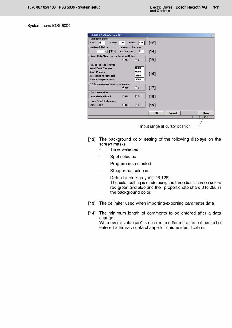
[12]
[13] [14]
[15]
[16]
[17]
[18]
[19]
Input range at cursor position
[12] The background color setting of the following displays on thescreen masks- Timer selected
- Spot selected
- Program no. selected
- Stepper no. selected
Default = blue-grey (0,128,128).The color setting is made using the three basic screen colorsred green and blue and their proportionate share 0 to 255 inthe background color.
[13] The delimiter used when importing/exporting parameter data
[14] The minimum length of comments to be entered after a datachangeWhenever a value � 0 is entered, a different comment has to beentered after each data change for unique identification.

3-12 Electric Drivesand Controls
Bosch Rexroth AG PSS 5000 - System setup 1070 087 054 / 03
System menu BOS-5000
[15] Transmission of the date and time of the programming terminal tothe timerWhen this function is turned off, there may be differences betweenthe date and time stored in the programming terminal and the weldtimers. Protocols are generated including the timer date and time.Date and time are transmitted if the function is switched on for:- Backup
- Auto. Backup
- Timer change
[16] The number of protocol memory entries recordedProtocol memory entries are organized according to the �First-in-First-out� principle, i.e, when the number of protocol memory en-tries is exceeded, the oldest entries are deleted.
[17] Recording of the %I value monitoring When this function is switched off, the %I monitoring value has tobe programmed separately.When it is turned on, the %I monitoring value is automatically pro-grammed when entering the commanded current.
ATTENTION!If the %I monitoring value is automatically recorded, it may still benecessary to adjust the %I monitoring value after a command value inputfor short weld times or active slope.
[18] Immediate printing of the documentation Preliminary decision for subsequent generation of the documenta-tion.- Print documentation to file.- Print documentation immediately.
[19] If turned �On�, the data of the Spot Reference and the Timer Refer-ence are also copied to the selected Backup directory. Copying isperformed for Backup and Auto-Backup.
!

Electric Drivesand Controls
4-1Bosch Rexroth AGPSS 5000 - System setup1070 087 054 / 03
Order data
4 Order data
Description Part no.
System disk on request

4-2 Electric Drivesand Controls
Bosch Rexroth AG PSS 5000 - System setup 1070 087 054 / 03
Order data
Notes:

Electric Drivesand Controls
A-1Bosch Rexroth AGPSS 5000 - System setup1070 087 054 / 03
Annex
A Annex
A.1 Index
Symbols%I monitoring value, 3-12%I Prewarning Table , 3-10
AAccess management, 2-2, 3-2
Procedure, 2-3Allocation table, 3-4ATTENTION, 1-1Automatic data transmission, 3-10Automatic Login, 3-9Automatic Logout, 3-9Automatic protocol generation, 3-9
BBackground color, 3-11BOS_5000.INI, 3-8BOS_MASK.TXT, 3-1, 3-6BOS_PASS.TXT, 3-1, 3-7BOS_USER.TXT, 3-1, 3-5
CCardiac pacemakers, 1-4, 1-5Comments, Length, 3-11
DData change protocol , 3-9Date, 3-12Delimiter, 3-11DEMO, 2-1Destination folder, 3-9Documentation, 3-12
EEU Machinery Directive, 1-1
FFault code, 3-10Fault protocol, 3-9, 3-10Fault Table , 3-10
LLanguage, 3-8Login, 2-1
MMask file, 3-6Modifications, 1-3
Modify-Level, 3-6
NNOTE, 1-1
PProper use, 1-3Protocol, 3-9Protocol memory, Delete, 3-7Protocol memory entries, 3-12Protocol memory setup, 3-7Protocol time , 3-9
QQualified personnel, 1-5
RRead-Level, 3-6Refresh time, Tables, 3-10
SSelection, 3-8Stepper Prewarning Table , 3-10System disk, 3-1
Login, 3-1System menu, 3-1System setup, 2-1, 3-8
Figure 2, 3-10
TTime, 3-12Timer Status window, 3-10Training, 1-5Typographic conventions , 1-3
UUser disk, 3-7User file, 3-5User group, 3-3User groups, 3-3User level, 3-4User password, 3-3User table, 3-2, 3-4
WWARNING, 1-1Weld fault protocol , 3-9Windows Setup, 3-2

A-2 Electric Drivesand Controls
Bosch Rexroth AG PSS 5000 - System setup 1070 087 054 / 03
Annex
Notes:

Electric Drivesand Controls
A-1Bosch Rexroth AGPSS 5000 - System setup1070 087 054 / 03
Bosch Rexroth AGElectric Drives and ControlsBgm.-Dr.-Nebel-Str. 297816 Lohr a. Main, [email protected]
Printed in GermanyDOK-PS5000-Systeminfo*-PA03-EN-P