Rexroth SYNAX 200 Modular system solution for shaftless printing
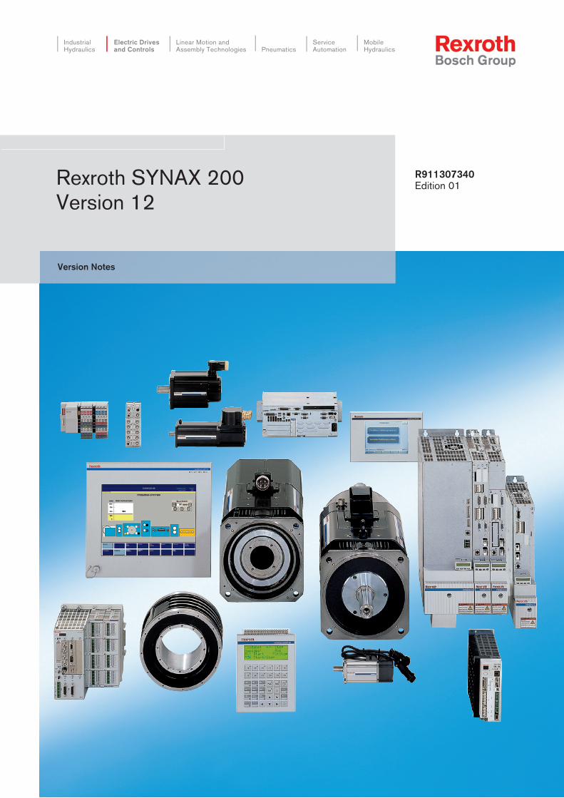
Rexroth IndraControl VCP 20
IndustrialHydraulics
Electric Drivesand Controls
Linear Motion and Assembly Technologies Pneumatics
ServiceAutomation
MobileHydraulics
Rexroth SYNAX 200Version 12
R911307340Edition 01
Version Notes

About this Documentation Rexroth SYNAX 200
DOK-SYNAX*-SY*-12VRS**-FV01-EN-P
Rexroth SYNAX 200
Version 12
Version Notes
DOK-SYNAX*-SY*-12VRS**-FV01-EN-P
• Box 40-12V-EN
• SY112E_V.doc
• Document number 120-2200-B350-01/EN
The documentation gives an overview about the new and changedfunctionalities of SYNAX 200 version 12 compared with the previousversion 11.
Description ReleaseDate
Notes
DOK-SYNAX*-SY*-12VRS**-FV01-EN-P 02.05 Version 12VRS
2004 Bosch Rexroth AG
Copying this document, giving it to others and the use or communicationof the contents thereof without express authority, are forbidden. Offendersare liable for the payment of damages. All rights are reserved in the eventof the grant of a patent or the registration of a utility model or design(DIN 34-1).
The specified data is for product description purposes only and may notbe deemed to be guaranteed unless expressly confirmed in the contract.All rights are reserved with respect to the content of this documentationand the availability of the product.
Bosch Rexroth AGBgm.-Dr.-Nebel-Str. 2 • D-97816 Lohr a. Main
Telephone +49 (0)93 52/40-0 • Tx 68 94 21 • Fax +49 (0)93 52/40-48 85
http://www.boschrexroth.com/
Dept. BRC/ESP (HJD)
This document has been printed on chlorine-free bleached paper.
Title
Type of Documentation
Document Typecode
Internal File Reference
Purpose of Documentation
Record of Revisions
Copyright
Validity
Published by
Note

Rexroth SYNAX 200 About this Documentation
DOK-SYNAX*-SY*-12VRS**-FV01-EN-P
Summary of Documentation - Overview
Order designation:DOK-SYNAX*-SY*-12V*1/2-FK01-EN-PDOK-SYNAX*-SY*-12V*2/2-FK01-EN-P
Order designation:DOK-SYNAX*-SY*-12VRS**-PA01-EN-P
Order designation:DOK-SYNAX*-SY*-12VRS**-WA01-EN-P
Order designation:DOK-SYNAX*-SY*-12VRS**-FV01-EN-P
Order designation:DOK-SYNAX*-SY*-12VRS**-PR01-EN-P
Functional Description; Interfaces:
Help familiarize the user with SYNAX 200and the functions of SYNAX 200
Parameter Description:
Description of the SYNAX 200 system parameters
Trouble Shooting Guide:
Explanation of the diagnostics statesHow to proceed when eliminating faults
Project Planning:
Selection of units and hardware componentsBasic control in cabinet construction
Order designation:DOK-SYNAX*-SY*-12VRS**-4001-EN-P
Firmware Version Notes:
Description of the new and changedfunctions between SYNAX 200 version 12and previous version 11
FK
PA
WA
FV
PR
About this Documentation Rexroth SYNAX 200
DOK-SYNAX*-SY*-12VRS**-FV01-EN-P

Rexroth SYNAX 200 Contents I
DOK-SYNAX*-SY*-12VRS**-FV01-EN-P
Contents
1 References 1-1
1.1 Product family ............................................................................................................................... 1-1
1.2 Referenced hardware ................................................................................................................... 1-1
1.3 Reference list firmware/software .................................................................................................. 1-4
Motion control firmware ........................................................................................................... 1-4
Drive firmware.......................................................................................................................... 1-5
Commissioning interface / PLC programming interface.......................................................... 1-7
Firmware download ................................................................................................................. 1-7
Cam tool .................................................................................................................................. 1-7
HMI software............................................................................................................................ 1-8
Control terminals of VEP series............................................................................................... 1-8
Miniature control terminals of VCP series ............................................................................... 1-9
1.4 System documentation ................................................................................................................. 1-9
Motion control components ..................................................................................................... 1-9
Drive components.................................................................................................................. 1-10
Visualization units PC based ................................................................................................. 1-10
Visualization units Windows CE based ................................................................................. 1-10
Miniature control terminals VCP............................................................................................ 1-11
2 SYNAX 200 firmware version 12VRS 2-1
2.1 Release notes on SYNAX 200 firmware version 12V01 .............................................................. 2-1
2.2 Flash module labellings ................................................................................................................ 2-1
2.3 New functions ............................................................................................................................... 2-2
Support of new hardware ........................................................................................................ 2-2
Scalable Sercos cycle time in the SYNAX-Ring...................................................................... 2-2
Free configurable cyclical SERCOS data container................................................................ 2-2
Support of onboard IO’s on the PPC....................................................................................... 2-3
Execution of binary SYNAX IO’s ............................................................................................. 2-3
Continous probe input function................................................................................................ 2-3
Data exchange between PPC’s with Indralogic....................................................................... 2-3
Communication with the programming software Indralogic via Ethernet ................................ 2-3
Simple configuration of the cyclical process data channel between MotionControland integrated PLC.................................................................................................................. 2-3
New library-, function block- and I/O - notations in IndraLogic................................................ 2-4
New functionalities in libraries of the integrated PLC.............................................................. 2-5
New libraries in the integrated PLC......................................................................................... 2-8
New browser commands ......................................................................................................... 2-8
New tool for the determination of installed system components ............................................. 2-8
II Contents Rexroth SYNAX 200
DOK-SYNAX*-SY*-12VRS**-FV01-EN-P
2.4 Porting a PLC project based on SYNAX Version 11 to a SYNAX Version 12 based PLCproject ........................................................................................................................................... 2-9
2.5 New parameters, I/Os and diagnostics....................................................................................... 2-10
New Y parameters................................................................................................................. 2-10
New C parameters................................................................................................................. 2-10
New A parameters................................................................................................................. 2-11
New inputs/outputs ................................................................................................................ 2-11
New diagnostic messages..................................................................................................... 2-12
2.6 Changed and extended functions............................................................................................... 2-13
Register controller.................................................................................................................. 2-13
Tension controller with load cell ............................................................................................ 2-13
Fieldbus communication........................................................................................................ 2-13
2.7 Changed and extended parameters, I/Os and diagnostics ........................................................ 2-14
Changed Y parameters ......................................................................................................... 2-14
Changed C parameters ......................................................................................................... 2-17
Changed A parameters ......................................................................................................... 2-17
Changed inputs/outputs......................................................................................................... 2-19
Changed diagnostic messages ............................................................................................. 2-21
2.8 Phase out of functions / hardware .............................................................................................. 2-21
Following hardware is no longer supported by the SYNAX 12V01: ...................................... 2-21
3 Service & Support 3-1
3.1 Helpdesk....................................................................................................................................... 3-1
3.2 Service-Hotline ............................................................................................................................. 3-1
3.3 Internet.......................................................................................................................................... 3-1
3.4 Vor der Kontaktaufnahme... - Before contacting us... .................................................................. 3-1
3.5 Kundenbetreuungsstellen - Sales & Service Facilities ................................................................. 3-2

Rexroth SYNAX 200 References 1-1
DOK-SYNAX*-SY*-12VRS**-FV01-EN-P
1 References
1.1 Product family
The firmware version description references the product family:
SYNAX 200 Decentralized System for the Synchronization of MachineAxes.
Current firmware versions: FWA-PPCPR*-SY*-12VRS-D0,
FWA-PPCPR*-SL*-12VRS-D0,
FWA-PPCPR*-SLE*-12VRS-D0.
1.2 Referenced hardware
Permissible module carrier• RMB02.2-02 (for installation of 2 modules)
• RMB02.2-04 (for installation of 4 modules)
Permissible controls• PPC-R22.1N-N (2 RECO slots, up to 3 expansion cards)
• PPC-R22.1N-T(2 RECO slots, Ethernet on board, up to 3 expansion cards)
• PPC-P11.1N-N (PCI plug-in card, up to 3 expansion cards)
Fieldbus slave interfaces PPC-R2x and PPC-P11• DAQ03 (option Q1, cross link and/or ARCNET)
• DAQ04 (option Q2, cross link and/or ARCNET)
• DPS01 (option P2, Profibus slave)
• DNS03 (option V2, DeviceNet slave)
Fieldbus slave interfaces for PPC-P11• ETH01 (option T2, Ethernet/IP, Ethernet)
Fieldbus master interfaces for integrated PLC• DPM01DPM01 (option P1, Profibus master)
• DNM03 (option V1, DeviceNet master)
Function module for master encoder• LAG (option G2, 2 master encoder interfaces)

1-2 References Rexroth SYNAX 200
DOK-SYNAX*-SY*-12VRS**-FV01-EN-P
RECO local bus, I/O modules• RME02.2-16-DC024 (digital inputs)
• RME02.2-32-DC024 (digital inputs)
• RME02.2-16-AC115 (digital inputs)
• RMA02.2-16-DC024-200 (digital outputs)
• RMA02.2-32-DC024-050 (digital outputs)
• RMA02.2-16-AC230-200 (digital outputs)
• RMA02.2-16-RE230-200 (digital outputs)
RECO local bus, module for integrated PLC• RMC02.2-2E-1A (analog module 2 x input, 1 x output)
RECO Inline, fieldbus modules for the integrated PLC(slave interfaces)Fieldbus coupling modules:
• R-IL PB BK (PROFIBUS-DP bus clamp)
• R-IL DN-BK (DeviceNet bus clamp)
Digital input modules:
• R-IB IL 24 DI 2 (clamp with 2 digital inputs)
• R-IB IL 24 DI 4 (clamp with 4 digital inputs)
• R-IB IL 24 DI 8 (clamp with 8 digital inputs)
• R-IB IL 24 DI 16 (clamp with 16 digital inputs)
• R-IB IL 24 DI 32/HD (clamp with 32 digital inputs)
• R-IB IL 24 EDI 2-DES (clamp with 2 digital and 2 diagnostic inputs)
Digital output modules:
• R-IB IL 24 DO 2-2A (clamp with 2 digital outputs 2A)
• R-IB IL 24 DO 4 (clamp with 4 digital outputs 500 mA)
• R-IB IL 24 DO 8 (clamp with 4 digital outputs 500 mA)
• R-IB IL 24 DO 8-2A (clamp with 8 digital outputs 2A)
• R-IB IL 24 DO 16 (clamp with 16 digital outputs 500 mA)
• R-IB IL 32/DO 32/HD (clamp with 32 digital outputs)
Analog In/Output modules:
• R-IB IL AI 2/SF (clamp with 2 analog input channels)
• R-IB IL AL 8/SF (clamp with 8 analog inputs voltage/current)
• R-IB IL AL 8/IS (clamp with 8 analog input, only current)
• R-IB IL 24 TEMP 2 RTD (clamp with 2 input channels for connectionof temperature resistors)
• R-IB IL 24 AO 1/SF (clamp with 1 analog output channel)
• R-IB IL 24 AO 2 U/BP (clamp with 2 analog voltage outputs)

Rexroth SYNAX 200 References 1-3
DOK-SYNAX*-SY*-12VRS**-FV01-EN-P
Other modules:
• R-IB IL 24/230 DOR 1/W (clamp with 1 relay output)
• R-IB IL 24/230 DOR 4/W (clamp with 4 relay outputs)
• R-IB IL DOR LV-SET (clamp pair as accessory for relay clamp)
• R-IB IL 24 CNT (function clamp counter – timer)
• R-IB IL PWR IN (supply clamp)
• R-IB IL SEG/F (segment clamp)
Block I/O-modules:
• R-ILB 24 DI16 DO16(Profibus-DP 16 digital inputs, 16 digital outputs)
• R-ILB DN 24 DI16 DO16 (DeviceNet 16 digital inputs, 16 digitaloutputs)
Drive families• Diax 03
• Diax 04
• IndraDrive
• EcoDrive 03
• EcoDrive Cs

1-4 References Rexroth SYNAX 200
DOK-SYNAX*-SY*-12VRS**-FV01-EN-P
1.3 Reference list firmware/software
Note: The software with suffix -COPY may be copied.
Motion control firmware
SYNAX 200 MotionControl PPC-R2x and PPC-P withoutPLC
Product:Product firmware(order designation):
Printed board firmware(flash module labelling):
PPC-R2x or PPC-P FWA-PPCPR*-SY*-12VRS-D0-XXXXXX FWC-PFM01*-SY*-12VRS-D0
PPC-R2x or PPC-P+ Profibus slave
FWA-PPCPR*-SY*-12VRS-D0-P2XXXX FWC-PFM01*-SY*-12VRS-D0FWC-DPS01*-PHP-02VRS-NN
PPC-R2x or PPC-P+ DeviceNet slave
FWA-PPCPR*-SY*-12VRS-D0-V2XXXX FWC-PFM01*-SY*-12VRS-D0FWC-DNS01*-PHV-01VRS-NN
Fig. 1-1: SYNAX 200 MotionControl PPC-R2x or PPC-P without PLC
SYNAX 200 MotionControl PPC-R2x and PPC-P with PLC(MotionLogic)
Product:Product firmware(order designation):
Printed board firmware(flash module labelling):
PPC-R2x or PPC-P FWA-PPCPR*-SL*-12VRS-D0-XXXXXX FWC-PFM01*-SL*-12VRS-D0
PPC-R2x or PPC-P+ Profibus slave
FWA-PPCPR*-SL*-12VRS-D0-P2XXXX FWC-PFM01*-SL*-12VRS-D0FWC-DPS01*-PHP-02VRS-NN
PPC-R2x or PPC-P+ DeviceNet slave
FWA-PPCPR*-SL*-12VRS-D0-V2XXXX FWC-PFM01*-SL*-12VRS-D0FWC-DNS01*-PHV-01VRS-NN
PPC-R2x or PPC-P+ Profibus master
FWA-PPCPR*-SL*-12VRS-D0-P1XXXX FWC-PFM01*-SL*-12VRS-D0FWC-DPM01*-PHP-02VRS-NN
PPC-R2x or PPC-P+ DeviceNet master
FWA-PPCPR*-SL*-12VRS-D0-V1XXXX FWC-PFM01*-SL*-12VRS-D0FWC-DNM03*-PHV-01VRS-NN
PPC-R2x or PPC-P+ Profibus master+ Profibus slave
FWA-PPCPR*-SL*-12VRS-D0-P1P2XX FWC-PFM01*-SL*-12VRS-D0FWC-DPM01*-PHP-02VRS-NNFWC-DPS01*-PHP-02VRS-NN
PPC-R2x or PPC-P+ DeviceNet master+ DeviceNet slave
FWA-PPCPR*-SL*-12VRS-D0-V1V2XX FWC-PFM01*-SL*-12VRS-D0FWC-DNM03*-PHV-01VRS-NNFWC-DNS01*-PHV-01VRS-NN
Fig. 1-2: SYNAX 200 MotionControl PPC-R2x with PLC (MotionLogic)

Rexroth SYNAX 200 References 1-5
DOK-SYNAX*-SY*-12VRS**-FV01-EN-P
SYNAX 200 MotionControl PPC-R2x and PPC-P with PLC(MotionLogic economy)
Product:Product firmware(order designation):
Printed board firmware(flash module labelling):
PPC-R2x or PPC-P FWA-PPCPR*-SLE-12VRS-D0-XXXXXX FWC-PFM01*-SLE-12VRS-D0
PPC-R2x or PPC-P+ Profibus slave
FWA-PPCPR*-SLE-12VRS-D0-P2XXXX FWC-PFM01*-SLE-12VRS-D0FWC-DPS01*-PHP-02VRS-NN
PPC-R2x or PPC-P+ DeviceNet slave
FWA-PPCPR*-SLE-12VRS-D0-V2XXXX FWC-PFM01*-SLE-12VRS-D0FWC-DNS01*-PHV-01VRS-NN
Fig. 1-3: SYNAX 200 MotionControl PPC-R2x with PLC (MotionLogic economy)
Drive firmware
Full versions: firmware for synchronous axis with allauxiliary modes
Product:Product firmware(order designation):
Printed board firmware(EPROM/flash module labelling):
Drive familyIndraDrive
FWA-INDRV*-MPH-03VRS-D5-1-SNC-NN FWC-CSH1.1-MPH-03VRS-MSFWC-HSI11*-SST-01VRS-MS
Drive family IndraDrive +all packages
FWA-INDRV*-MPH-03VRS-D5-1-ALL-NN FWC-CSH1.1-MPH-03VRS-MSFWC-HSI11*-SST-01VRS-MS
Drive family IndraDrive +PLC
FWA-INDRV*-MPH-03VRS-D5-1-SNC-ML FWC-CSH1.1-MPH-03VRS-MSFWC-HSI11*-SST-01VRS-MS
Drive family IndraDrive +all packages + PLC
FWA-INDRV*-MPH-03VRS-D5-1-ALL-ML FWC-CSH1.1-MPH-03VRS-MSFWC-HSI11*-SST-01VRS-MS
Drive familyIndraDrive Basic
FWA-INDRV*-MPB-03VRS-D5-1-SNC-NN FWC-CSB1.1-MPB-03VRS-MSFWC-HSI11*-SST-01VRS-MS
Drive familyIndraDrive Basic + PLC
FWA-INDRV*-MPB-03VRS-D5-1-SNC-TF FWC-CSB1.1-MPB-03VRS-MSFWC-HSI11*-SST-01VRS-MS
Drive family IndraDriveBasic + all packages
FWA-INDRV*-MPB-03VRS-D5-1-ALL-NN FWC-CSB1.1-MPB-03VRS-MSFWC-HSI11*-SST-01VRS-MS
Drive family IndraDriveBasic + all packages +PLC
FWA-INDRV*-MPB-03VRS-D5-1-ALL-TF FWC-CSB1.1-MPB-03VRS-MSFWC-HSI11*-SST-01VRS-MS
Drive family IndraDriveBasic Double Axis
FWA-INDRV*-MPD-03VRS-D5-1-SNC-NN FWC-CDB1.1-MPD-03VRS-MSFWC-HSI11*-SST-01VRS-MS
Drive family IndraDriveBasic Double Axis+ all packages
FWA-INDRV*-MPD-03VRS-D5-1-ALL-NN FWC-CDB1.1-MPD-03VRS-MSFWC-HSI11*-SST-01VRS-MS
Drive familyEcoDrive03
FWA-DRIVE*-SGP-20VRS-MS FWC-ESM2.2-SGP-20VRS-MS
Drive family DKR FWA-DIAX03-ELS-06VRS-MS FWC-DSM2.3-ELS-06VRS-MS
Drive family Diax 04 FWA-DIAX04-ELS-06VRS-MS FWC-HSM1.1-ELS-06VRS-MS
Fig. 1-4: Drive firmware (synchronization, positioning mode, idle mode)

1-6 References Rexroth SYNAX 200
DOK-SYNAX*-SY*-12VRS**-FV01-EN-P
Firmware for positioning mode and idle mode
Product:Product firmware(order designation):
Printed board firmware(EPROM/flash module labelling):
Drive family IndraDriveBasic
FWA-INDRV*-MPB-03VRS-D5-1-NNN-NN FWC-CSB1.1-MPB-03VRS-MSFWC-HSI11*-SST-01VRS-MS
Drive familyIndraDrive Basic + PLC
FWA-INDRV*-MPB-03VRS-D5-1-NNN-TF FWC-CSB1.1-MPB-03VRS-MSFWC-HSI11*-SST-01VRS-MS
Drive family IndraDriveBasic Double Axis
FWA-INDRV*-MPD-03VRS-D5-1-NNN-NN FWC-CDB1.1-MPD-03VRS-MSFWC-HSI11*-SST-01VRS-MS
Drive familyEcoDrive Cs
FWA-ECODR3-MGP-01VRS-MS FWC-ECODR3-MGP-01VRS-MS
Drive familyEcoDrive 03
FWA-ECODR3-SMT-02VRS-MS FWC-ESM2.1-SMT-02VRS-MS
Fig. 1-5: Drive firmware (positioning and idle mode)
Firmware for speed synchronous and speed-controlledaxis without encoder (speed synchronization and idlemode)
Product:Product firmware(order designation):
Printed board firmware(EPROM/flash module labelling):
Drive family IndraDrive FWA-INDRV*-MPH-03VRS-D5-0-SNC-NN FWC-CSH1.1-MPH-03VRS-MSFWC-HSI11*-SST-01VRS-MS
Drive familyIndraDrive + PLC
FWA-INDRV*-MPH-03VRS-D5-0-SNC-ML FWC-CSH1.1-MPH-03VRS-MSFWC-HSI11*-SST-01VRS-MS
Drive familyIndraDrive Basic
FWA-INDRV*-MPB-03VRS-D5-0-SNC-NN FWC-CSB1.1-MPB-03VRS-MSFWC-HSI11*-SST-01VRS-MS
Drive familyIndraDrive Basic + PLC
FWA-INDRV*-MPB-03VRS-D5-0-SNC-TF FWC-CSB1.1-MPB-03VRS-MSFWC-HSI11*-SST-01VRS-MS
Drive family IndraDriveBasic Double Axis
FWA-INDRV*-MPD-03VRS-D5-0-SNC-NN FWC-CDB1.1-MPD-03VRS-MSFWC-HSI11*-SST-01VRS-MS
Fig. 1-6: Drive firmware (speed synchronization and idle mode)
Firmware for speed-controlled axis without encoder (idlemode)
Product:Product firmware(order designation):
Printed board firmware(EPROM/flash module labelling):
Drive family IndraDrive FWA-INDRV*-MPH-03VRS-D5-0-NNN-NN FWC-CSH1.1-MPH-03VRS-MSFWC-HSI11*-SST-01VRS-MS
Drive familyIndraDrive + PLC
FWA-INDRV*-MPH-03VRS-D5-0-NNN-ML FWC-CSH1.1-MPH-03VRS-MSFWC-HSI11*-SST-01VRS-MS
Drive familyIndraDrive Basic
FWA-INDRV*-MPB-03VRS-D5-0-NNN-NN FWC-CSB1.1-MPB-03VRS-MSFWC-HSI11*-SST-01VRS-MS
Drive family IndraDriveBasic + PLC
FWA-INDRV*-MPB-03VRS-D5-0-NNN-TF FWC-CSB1.1-MPB-03VRS-MSFWC-HSI11*-SST-01VRS-MS
Drive family IndraDriveBasic Double Axis
FWA-INDRV*-MPD-03VRS-D5-0-NNN-NN FWC-CDB1.1-MPD-03VRS-MSFWC-HSI11*-SST-01VRS-MS
Fig. 1-7: Drive firmware (idle mode)

Rexroth SYNAX 200 References 1-7
DOK-SYNAX*-SY*-12VRS**-FV01-EN-P
Commissioning interface / PLC programming interface
Product:Product software(order designation): CD labelling
Parameterization and PLCprogramming interfaceSynTop and IndraLogic
SWA-SYNAX*-INB-12VRS-D0-CD650-COPY SWD-SYNAX*-INB-12VRS-D0-CD650
Fig. 1-8: Commissioning software
Firmware download
Product:Product software(order designation): Disk labelling
DOLFI tool for downloadof firmware
SWA-DOL*PC-INB-01VRS-MS-C1,44-COPY SWD-DOL*PC-INB-01VRS-MS-C1,44
Fig. 1-9: Firmware download
Note: DOLFI can be found on the CD SWA-SYNAX*-INB-12VRS-D0-CD650-COPY.
Cam tool
Product:Product software(order designation): CD labelling
CamBuilder SWA-CAM*PC-INB-01VRS-D0-CD650 SWD-CAM*PC-INB-01VRS-D0-CD650
CamBuilder(demo version)
SWA-CAM*PC-INB-01DRS-D0-CD650 SWD-CAM*PC-INB-01DRS-D0-CD650
Fig. 1-10: Cam tool

1-8 References Rexroth SYNAX 200
DOK-SYNAX*-SY*-12VRS**-FV01-EN-P
HMI software
Product:Product software(order designation):
Product software(CD labelling):
Engineering
HMI for SYNAX 200 SWA-SYNAX*-HMI-12VRS-D0-CD650 SWD-SYNAX*-HMI-12VRS-D0-CD650
License for WinStudioprogramming interface
SWS-WINSTU-RUD-06VRS-D0-64K 64000 variables, 1024 array size,64 class members,target system WinNT/2000/XP/CE
License for WinStudioprogramming interface
SWS-WINSTU-RUD-06VRS-D0-4K 4000 variables, 512 array size,32 class memberstarget system WinNT/2000/XP/CE
License for WinStudioprogramming interface
SWS-WINSTU-RUD-06VRS-D0-1K5 1500 variables, 256 array size,32 class memberstarget system WinNT/2000/XP/CE
Runtime licenses (PC)
Runtime license forWinStudio-HMI
SWS-WINSTU-RUN-06VRS-D0-64K 64000 variables, 1024 array size,64 class memberstarget system WinNT/2000/XP
Runtime license forWinStudio-HMI
SWS-WINSTU-RUN-06VRS-D0-4K 4000 variables, 512 array size,32 class memberstarget system WinNT/2000/XP
Runtime license forWinStudio-HMI
SWS-WINSTU-RUN-06VRS-D0-1K5 1500 variables, 256 array size,32 class memberstarget system WinNT/2000/XP
Fig. 1-11: HMI software
Control terminals of VEP series
Product:Product software/firmware(order designation): Description
VEP firmware
VEP 30/40/50 FWA-VE**01-CWL-01VRS-D0 Windows CE 4.2 .NET with WinStudio
Runtime licenses
Runtime license forWinStudio-HMI atWindows CE
SWS-WINSTU-RUN-06VRS-D0-WCE4K 4000 variables, 512 array size,32 class memberstarget system Windows CE
Runtime license forWinStudio-HMI atWindows CE
SWS-WINSTU-RUN-06VRS-D0-WCE1K5 1500 variables, 256 array size,32 class memberstarget system Windows CE
Fig. 1-12: Visualization units VEP

Rexroth SYNAX 200 References 1-9
DOK-SYNAX*-SY*-12VRS**-FV01-EN-P
Miniature control terminals of VCP series
Product:Product software/firmware(order designation):
Disk labelling/Printed board firmware(EPROM/flash module labelling)
Project planning softwareVI-Composer
SWA-VIC*PC-INB-01VRS-D0-CD650 SWD-VIC*PC-INB-01VRS-D0-CD650
Download tool forVCP devices
DOK-SUPPL*-VCP*VID*V01-IB04-D0-D0650
Fig. 1-13: Visualization units VCP
1.4 System documentation
Additional information of the components can be found in the followingdocumentations.
Motion control components
Order designation Title
DOK-SYNAX*-SY*-12V*1/2-FK01-EN-P Rexroth SYNAX 200 - Functional Description
DOK-SYNAX*-SY*-12V*2/2-FK01-EN-P Rexroth SYNAX 200 - Interfaces Description
DOK-SYNAX*-SY*-12VRS**-PA01-EN-P Rexroth SYNAX 200 - Parameter Description
DOK-SYNAX*-SY*-12VRS**-PR01-EN-P Rexroth SYNAX 200 - Project Planning Manual
DOK-SYNAX*-SY*-12VRS**-WA01-EN-P Rexroth SYNAX 200 - Troubleshooting Guide
DOK-SYNAX*-SY*-12VRS**-FV01-EN-P Rexroth SYNAX 200 - Version Notes
DOK-SYNAX*-SY*-12VRS**-4001-EN-P Rexroth SYNAX 200 - Box 40-12V
SWA-SYNAX*-INB-12VRS-D0-CD650-COPY General help for Rexroth SYNAX 200 - version 12VRS
DOK-SYNAX*-SY*-12VRS**-IB01-EN-P Rexroth SYNAX 200 Version 12 - System Installation - First steps -Commissioning Manual
DOK-SYNAX*-IL*-12VRS**-AW01-EN-P Rexroth SYNAX 200 - MotionLogic Version 12 - Application Manual
DOK-SYNAX*-IL*-12VRS**-4101-EN-P Rexroth SYNAX 200 - MotionLogic - Box 41-12V
DOK-CONTRL-IL**PRO*V01-AW01-EN-P PLC Programming with Rexroth IndraLogic 1.0 - Operating andProgramming Guide
DOK-CONTRL-R-IL*PB*-BK-FK02-EN-P Rexroth Inline Profibus DP - Functional Description
DOK-CONTRL-R-IL*PBSSYS-AW02-EN-P Rexroth Inline Profibus DP - Application Manual
DOK-CONTRL-R-IL*DIO***-FK03-EN-P Rexroth Inline Digital I/O Terminals - Functional Description
DOK-CONTRL-R-IL*AIO***-FK02-EN-P Rexroth Inline Analog I/O Terminals - Project Planning Manual
DOK-CONTRL-R-IL*CNT***-AW02-EN-P Rexroth Inline Counter terminal - R-IB IL CNT
DOK-CONTRL-RF-FLS-PB**-PR02-EN-P Rexroth Fieldline PROFIBUS Devices- Project Planning Manual
DOK-CONTRL-RF-FLS-PB**-AW01-EN-P Rexroth Fieldline PROFIBUS Devices- Application Manual
Fig. 1-14: Documentation: motion control components

1-10 References Rexroth SYNAX 200
DOK-SYNAX*-SY*-12VRS**-FV01-EN-P
Drive components
Order designation Title
DOK-DIAX03-DKR********-PR02-EN-P DKR02, DKR03 and DKR04 Drive Controllers - Project Planning Manual
DOK-DIAX03-ELS-06VRS**-IF01-EN-P DIAX 03 - Brief Description
DOK-DIAX04-HDD+HDS**G2-PR05-EN-P Diax 04 HDD and HDS Controllers 2nd Generation - Project PlanningManual
DOK-DIAX04-PLUG*IN*MOD-PR03-EN-P Diax 04 Plug-in modules for Digital Intelligent Drive Controllers - ProjectPlanning Manual
DOK-DIAX04-ELS-06VRS**-6001-EN-P Diax 04 - Box 60-06V
DOK-POWER*-HVE+HVR**G2-AW07-EN-P Diax 04 HVE and HVR 2nd Generation Power Supply Units - ApplicationDescription
DOK-INDRV*-HMD+HMS****-PR02-EN-P Rexroth IndraDrive M - Drive controllers - Power Section
DOK-INDRV*-CSH********-PR02-EN-P Rexroth IndraDrive - Drive controllers - Control Section
DOK-INDRV*-MP*-03VRS**-8101-EN-P Rexroth IndraDrive - Box 81-03V
DOK-ECODR3-DKC**.3****-PR05-DE-P EcoDrive 03 -Project Planning Manual
DOK-ECODR3-DKC**.3-CS*-PR01-EN-P Rexroth Ecodrive Cs - Project Planning Manual
DOK-DRIVE*-SGP-20VRS**-7201-EN-P Rexroth EcoDrive 03 - Box 72-01V
DOK-INDRV*-HCS02.1****-PR01-EN-P Rexroth IndraDrive C Drive Controllers Power Sections HCS02.1 - ProjectPlanning Manual
DOK-INDRV*-HCS03.1****-PR01-EN-P Rexroth IndraDrive C Drive Controllers Control Section HCS03.1 - ProjectPlanning Manual
DOK-GENERL-EMV********-PR02-EN-P Electromagnetic Compatibility (EMC) in Drive and Control Systems -Project Planning Manual
Fig. 1-15: Documentation: Drive components
Visualization units PC based
Order designation Title
DOK-SUPPL*-BTV16/40/60-PR01-EN-P Rexroth BTV 16.2/40.2/60.2 - Project Planning Manual
DOK-SUPPL*-IPC*40.2***-PR01-EN-P Rexroth IPC 40.2 - Project Planning Manual
DOK-SUPPL*-VSB*40*****-PR01-EN-P Rexroth VSB 40.1 - Project Planning Manual
DOK-SUPPL*-VDP16/40/60-PR01-EN-P Rexroth IndraControl VDP 16/40/60 - Project Planning Manual
DOK-SUPPL*-VSP*16/40**-PR01-EN-P Rexroth IndraControl VSP 16/40 - Project Planning Manual
DOK-SUPPL*-VPP*21.1***-PR01-EN-P Rexroth IndraControl VPP21.1 - Project Planning Manual
Fig. 1-16: Documentation: Visualization units
Visualization units Windows CE based
Order designation Title
DOK-SUPPL*-VEP20/30/40-PR01-EN-P Rexroth VEP 20/30/40 - Project Planning Manual
Fig. 1-17: Documentation: Visualization units

Rexroth SYNAX 200 References 1-11
DOK-SYNAX*-SY*-12VRS**-FV01-EN-P
Miniature control terminals VCP
Order designation Title
DOK-SUPPL*-VCP*01*****-PR01-EN-P Rexroth VCP 01 - Project Planning Manual
DOK-SUPPL*-VCP02******-PR02-EN-P Rexroth VCP 02 - Project Planning Manual
DOK-SUPPL*-VCP05******-PR02-EN-P Rexroth VCP 05 - Project Planning Manual
DOK-SUPPL*-VCP08******-PR02-EN-P Rexroth VCP 08 - Project Planning Manual
DOK-SUPPL*-VCP20******-PR02-EN-P Rexroth VCP 20 - Project Planning Manual
DOK-SUPPL*-VCP25******-PR02-EN-P Rexroth VCP 25 - Project Planning Manual
DOK-SUPPL*-VIC*BEDIEN-AW01-EN-P VCP operating concept - Application Manual
Fig. 1-18: Documentation: Miniature control terminals VCP
1-12 References Rexroth SYNAX 200
DOK-SYNAX*-SY*-12VRS**-FV01-EN-P

Rexroth SYNAX 200 SYNAX 200 firmware version 12VRS 2-13
DOK-SYNAX*-SY*-12VRS**-FV01-EN-P
2 SYNAX 200 firmware version 12VRS
2.1 Release notes on SYNAX 200 firmware version 12V01
The SYNAX 200 firmware version 12V01 was released
12.11.2004.
2.2 Flash module labellings
Module Labelling Firmware
Flash module PFM01.1 PFM01.1-032-FW295174 Kxx/yy
2 8 7 6 3 7
FWC-PFM01*-SY*-12V01-D0Kxx/yy
SN307354-xxxxx xxx
FWC-PFM01*-SY*-12V01
for PPC-R2x and PPC-P11
Motion only
Flash module PFM01.1 PFM01.1-032-FW295174 Kxx/yy
2 8 7 6 3 7
FWC-PFM01*-SL*-12V01-D0Kxx/yy
SN307353-xxxxx xxx
FWC-PFM01*-SL*-12V01
for PPC-R2x and PPC-P11
Motion + IndraLogic
Flash-Modul PFM01.1 PFM01.1-032-FW295174 Kxx/yy
2 8 7 6 3 7
FWC-PFM01*-SLE-12V01-D0Kxx/yy
SN307351-xxxxx xxx
FWC-PFM01*-SLE-12V01
for PPC-R2x and PPC-P11
Motion + IndraLogic
Fig. 2-1: Flash module labelling for version 12V01
2-14 SYNAX 200 firmware version 12VRS Rexroth SYNAX 200
DOK-SYNAX*-SY*-12VRS**-FV01-EN-P
2.3 New functions
Support of new hardware
The SYNAX 200 version 12VRS supports the following new hardwarecomponents:
PPC-link mounting card DAQ04With the new PC-104-Option card DAQ04 for PPC-link, the following newfunctionalities are supported:
• Sercos transfer rate in SYNAX and link ring up to 16 MBaud
• Support of up to 64 PPC-link participants
• Scalable link cycle time dependent on the max. link participants (2ms,4ms, 8ms)
• Support of „passive“ link participants. This are link participants whichsend no main axis positions to the link; they only can send main axispositions of other participants to the drives. Thereby the length of thelink telegram can be minimized
Sercos-Phase run-up in the link double ring is also possible at interruptedprimary ring
Master axis encoder cardWith the new PC104 option card for PPC-R2x and PPC-P it's possible toread in a master axis encoder directly on the MotionControl. Up to 2EnDat-encoder can be connected, e.g. Rexroth types GDS02.1 orGDM02.1.
Scalable Sercos cycle time in the SYNAX-RingAdjustable Sercos cycle time in the SYNAX-Ring dependent on thenumber of drives in the ring (2ms, 4ms, 8ms, 10ms, 16ms).
Free configurable cyclical SERCOS data containerIn the cyclical data container between MotionControl and drive masterdata telegram (MDT) and drive telegram (AT) in each case two freeconfigurable parameter can be configured.
Note: The use of the free configurable cyclical SERCOS datacontainer is only meaningful from drive firmware versionIndradrive MPxV03, since this drive firmware has a 8 bytewider cyclical channel.

Rexroth SYNAX 200 SYNAX 200 firmware version 12VRS 2-15
DOK-SYNAX*-SY*-12VRS**-FV01-EN-P
Support of onboard IO’s on the PPCThree binary inputs and two binary outputs are supported by the PPC.These IO's are on interface X1 and can be used by the help of the I/Ologic, resp. by the integrated PLC.
Execution of binary SYNAX IO’sThe binary SYNAX IO control signals (main axis, following axis, MotionControl, interconnection) can be executed now in the SERCOS cycle.
Note: For the Motion Logic firmware it is the default setting, in theMotion-Only firmware it must be adjusted in parameter Y-0-0531 „PPC – configured options“.
Continous probe input functionThis is a simple alternative to configure a continous probe input functionof the drive for any purposes.
Data exchange between PPC’s with IndralogicAn integrated PLC is able to exchange data via ethernet with anotherintegrated PLC on a PPC via so called network variables.
This data exchange is possible in both directions. Furthermore so calledbroadcast messages to all integrated controls are possible.
Note: The data exchange via network variables is only available withthe target "SYNAX 200 - MotionLogic 12VRS (PPC-R)".
Communication with the programming software Indralogic via EthernetThe communication with the programming software Indralogic is alsopossible now via Ethernet. This enables faster program downloads.
Simple configuration of the cyclical process data channel betweenMotionControl and integrated PLC
The cyclical process data channel between MotionControl and integratedPLC is now comfortable adjustable at only one place in IndraLogic by thehelp of selection dialogues. For the cyclical exchanged parameterdiagnostics in the IndraLogic marker memory are available now.

2-16 SYNAX 200 firmware version 12VRS Rexroth SYNAX 200
DOK-SYNAX*-SY*-12VRS**-FV01-EN-P
New library-, function block- and I/O - notations in IndraLogicIn the course of standardization of library-, function block-, function- andI/O- notations at Bosch Rexroth, the notations become adapted.
Library notaion SL11 Library notaion SL12
BinaryIO_MS11.lib MS_BaseSL12.lib
AcyclicComm_MSV01.lib MSV_AcyclicComm.lib
AcyclicComm_MS11.lib MS_AcyclicComm.lib
CamTable_MSV01.lib MSV_CamTable.lib
AdvanceMath.lib MS_AdvanceMath.lib
LoopControl.lib MS_LoopControl.lib
Diagnosis.lib RIL_Diagnosis.lib
CommonTypes.lib RIL_CommonTypes.lib
Utilities.lib RIL_Utilities.lib
ProfibusComm_MS11.lib MS_ProfibusComm.lib
Fig. 2-2: Overview of the modified notations in SYNAX 200 - MotionLogic -version 11 and version 12
MS_ProfibusComm.lib
Notation in SL11 Notation in SL12
FN_ASCII_TO_WORD MS_ASCIIToWordPb
FN_LOCK_ACCESS MS_LockAccessPb
FN_UNLOCK_ACCESS MS_UnlockAccessPb
FB_PB_RD_LIST_SF1 MS_ReadListArrayParameterPb
FB_PB_WR_LIST_SF1 MS_WriteListArrayParameterPb
FB_PB_CHANGE_PHASE_SIS MS_ChangePhasePb
FB_PB_RD_PHASE_SIS MS_ReadPhasePb
FB_PB_ABORT_TRANS_SIS MS_AbortServicePb
FB_PB_RD_ATTRIBUTE_SF1 MS_ReadAttributePb
FB_PB_RD_DATASTATUS_SF1 MS_ReadDataStatusPb
FB_PB_RD_DATALIST_SF1 MS_ReadDbParameterPb
FB_PB_RD_PARAMETER_SF1 MS_ReadParameterPb
FB_PB_WR_DATALIST_SF1 MS_WriteDbParameterPb
FB_PB_WR_PARAMETER_SF1 MS_WriteParameterPb
FB_PB_RD_MUX_DATA32 MS_ReadMuxLayer32Pb
FB_PB_WR_MUX_DATA32 MS_WriteMuxLayer32Pb
Fig. 2-3: Overview of the modified notations of the function blocks and functionsin SYNAX 200 - MotionLogic - version 11 and version 12

Rexroth SYNAX 200 SYNAX 200 firmware version 12VRS 2-17
DOK-SYNAX*-SY*-12VRS**-FV01-EN-P
Notation in SL11 Notation in SL12
FIELDBUS_IN MS_PB_FIELDBUS32_IN
FIELDBUS_OUT MS_PB_FIELDBUS32_OUT
ACYCLIC_IN MS_PB_ACYCLIC_IN
ACYCLIC_OUT MS_PB_ACYCLIC_OUT
CYCLIC_IN MS_PB_CYCLIC32_IN
CYCLIC_OUT MS_PB_CYCLIC32_OUT
Fig. 2-4: Overview of the modified notations of data types in SYNAX 200 -MotionLogic - version 11 and version 12
MS_AdvanceMath.lib
Notation in SL11 Notation in SL12
IL_DegToRad MS_DegToRad
IL_RadToDeg MS_RadToDeg
IL_MaxValue MS_MaxValue
IL_LinearInterpolation MS_LinearInterpolation
Fig. 2-5: Overview of the modified notations of function blocks and functions inSYNAX 200 - MotionLogic - version 11 and version 12
Notation in SL11 Notation in SL12
ValueTable MS_COORDINATE_PAIR_ TYPE02
Fig. 2-6: Overview of the modified notations of data types in SYNAX 200 -MotionLogic - version 11 and version 12
MS_LoopControl.lib
Notation in SL11 Notation in SL12
IL_TwoPointType01 MS_TwoPointType01
IL_PT1Type01 MS_PT1Type01
Fig. 2-7: Overview of modified notations of function blocks and functions inSYNAX 200 - MotionLogic - version 11 and version 12

2-18 SYNAX 200 firmware version 12VRS Rexroth SYNAX 200
DOK-SYNAX*-SY*-12VRS**-FV01-EN-P
New functionalities in libraries of the integrated PLCIn the so far libraries for the integrated PLC the adjacent listed newfunctionalities are available in IndraLogic.
MSV_CamTable.lib
Notation Type Description
MSV_CamTableType06 FBThe function block MSV_CamTableType06 calculates a camdisk tablewith 1024 base elements on basis of predetermined coordinate pairsconsisting of position [degrees] and velocity.
MSV_CamTableType07 FBThe function block MSV_CamTableType07 calculates a camdisk tablewith 1024 base elements on basis of predetermined coordinate pairsconsisting of position [degrees] and velocity.
MSV_CamTableType08 FBThe function block MSV_CamTableType08 calculates a camdisk tablewith 1024 base elements on basis of predetermined coordinate pairsconsisting of position [degrees] and acceleration
MSV_CamTableType09 FBThe function block MSV_CamTableType09 calculates a camdisk tablewith 1024 base elements on basis of predetermined coordinate pairsconsisting of position [degrees] and position.
MSV_CamTableType10 FBThe function block MSV_CamTableType10 calculates a camdisk tablewith 1024 base elements on basis of predetermined coordinate pairsconsisting of position [degrees] and position.
MSV_CamTableType11 FB
The function block MSV_CamTableType11 calculates a camdisk tablefor the technology function cross cutter, resp. rotation shears on basisof VDI2143. It combines MSV_CamTableType02 andMSV_CamTableType03 in a common function block.
MSV_CamTableType12 FBThe function block MSV_CamTableType12 calculates a camdisk tablewith 1024 base elements for the technology function print repeat rangecorrection on basis of VDI2143.
Fig. 2-8: Overview of the new function blocks and functions in libraryMSV_CamTable.lib
MS_AdvanceMath.lib
Notation Type Description
MS_DegToInc FNCThe function MS_DegToInc converts the predertermined angle indegree (0°<=x<360°) to the corresponding increment value(0<=x<2^20).
MS_IncToDec FNCThe function MS_IncToDec converts the predetermined angle inincrements (0<=x<2^20) to the corresponding angle in degree(0°<=x<360°).
MS_RadToInc FNC The function MS_RadToInc converts the predetermined angle inradian (0<=x<2*PI) to the corresponding increment value (0<=x<2^20).
MS_IncToRad FNCThe function MS_IncToRad converts the predetermined angel inincrements (0<=x<2^20) to the corresponding angle in radian(0<=x<2*PI).
Fig. 2-9: Overview of the new function blocks and functions in libraryMS_AdvanceMath.lib

Rexroth SYNAX 200 SYNAX 200 firmware version 12VRS 2-19
DOK-SYNAX*-SY*-12VRS**-FV01-EN-P
MS_ProfibusComm.lib
Notation Type Description
MS_ReadMuxLayer64Pb FB The function block MS_ReadMultiplexLayer64 is used for reading amultiplex layer (64 words fieldbus data).
MS_WriteMuxLayer64Pb FB The function block MS_WriteMultiplexLayer64 is used for writing amultiplex layer (64 wods fieldbus data).
Fig. 2-10: Overview of the new function blocks and functions in libraryMS_ProfibusComm.lib
MS_LoopControl.lib
Notation Type Description
MS_PIDType01 FB The function block MS_PIDType01 implements a PID controller withpause, preset and anti-reset-windup.
Fig. 2-11: Overview of the new function blocks and functions in libraryMS_LoopControl.lib
MS_BaseSL12.lib
Notation Type Description
MS_COORDINATE_PAIR_TYPE01 STRUCT Coordinate pair (LREAL, LREAL)
MS_COORDINATE_PAIR_TYPE02 STRUCT Coordinate pair (DINT, DINT)
Fig. 2-12: Overview of new data types in library MS_BaseSL12.lib

2-20 SYNAX 200 firmware version 12VRS Rexroth SYNAX 200
DOK-SYNAX*-SY*-12VRS**-FV01-EN-P
New libraries in the integrated PLCAdditionally to the so far libraries the following new libraries withsubsequent listed content are available.
MSV_CheckRtv.libThe library contains blocks for automatic monitoring of the PLC programcode related to runtime errors (division by zero, range exceeding in arraysand variables).
Notation Type Description
CheckBounds FNC The function CheckBounds is used for automatic check related torange exceeeding of the array index.
CheckDivByte FNC The function CheckDivByte is used for automatic check of the divisorrelated to a division by zero.
CheckDivWord FNC The function CheckDivWord is used for automatic check of the divisorrelated to a division by zero.
CheckDivDWord FNC The function CheckDivDWord is used for automatic check of thedivisor related to a division by zero.
CheckDivReal FNC The function CheckDivReal is used for automatic check of the divisorrelated to a division by zero.
CheckRangeSigned FNC The function CheckRangeSigned is used for automatic check relatedto the exceeding of the value range of a variable.
CheckRangeUnsigned FNC The function CheckRangeUnsigned is used for automatic checkrelated to the exceeding of the value range of a variable.
Fig. 2-13: Overview of the new function blocks and functions in libraryMSV_CheckRtv.lib
Note: The check takes place implicit by integration of the library, i.e.the functions must not be integrated in the program anothertime
NetVarUdp_LIB_V23.libThe library contains blocks for use of network variables and theparameter manager, i.e. for data exchange between two or severalcontrols.
Note: The library NetVarUdp_LIB_V23.lib is only available on target"SYNAX 200 - MotionLogic 12VRS (PPC-R)".
New browser commandsIn IndraLogic new browser commands are available. By the help of thiscommands, e.g. to detect the actualisation rate of the cyclic exchangedparameter, the PLC program can be optimized.
New tool for the determination of installed system componentsIn IndraLogic in register "Resources" in folder "Tools" the tool „SYNAX200 Information“ for determination of installed system componenents likeinstalled targets, version of installed IndraLogic, SynTop etc. is available.

Rexroth SYNAX 200 SYNAX 200 firmware version 12VRS 2-21
DOK-SYNAX*-SY*-12VRS**-FV01-EN-P
2.4 Porting a PLC project based on SYNAX Version 11 to aSYNAX Version 12 based PLC project
Variant 1 – Without conversion tool
• Save the existing project by a new name.
• Open the new saved project and change in register "Resources" infolder Target settings the configuration in the pull-down menu to„None“.
• Remove all listed libraries in register "Resources" in folder Librarymanager.
• Change in register "Resources" in folder Target settings theconfiguration in the pull-down-menu to „SYNAX200-MotionLogic12VRS (PPC-R)“, resp. "SYNAX200-MotionLogic 12VRS (PPC-P)".
• Reset these setting at open control configuration usingExtras/Standard configuration and insert all necessary I/Os at thecorresponding place. For orientation you can open IndraLogic anothertime with the original project.
• Insert again all not yet loaded necessary libraries, exchange renamedblocks and then compile the PLC project.
Variant 2 – With conversion tool via export file (in preparation)
• Export the complete project.
• Compile the export file by the help of the conversion tool.
• Create a new project with the corresponding target and import theconverted export file. Due to changes, add in the control configurationthe removed I/Os by help of the logfile at the corresponding place.
• Insert again all not yet loaded necessary libraries, exchange renamedblocks and then compile the PLC project.

2-22 SYNAX 200 firmware version 12VRS Rexroth SYNAX 200
DOK-SYNAX*-SY*-12VRS**-FV01-EN-P
2.5 New parameters, I/Os and diagnostics
New Y parameters
ID no. Name of parameter
Y-0-0017 Master encoder card - error class
Y-0-0018 Master encoder card - error group
Y-0-0019 Master encoder card - error number
Y-0-0025 Master encoder card - position value encoder 1
Y-0-0026 Master encoder card - position value encoder 2
Y-0-0034 Target cycle time
Y-0-0035 Cycle: minimal possible cycle time
Y-0-0036 Cycle: calculation time
Y-0-0037 Cycle: transmission time and realtime calculations
Y-0-0052 Master encoder card - hardware version
Y-0-0053 Master encoder card - firmware version
Y-0-0054 Master encoder card - encoder system
Y-0-0055 Master encoder card - encoder type
Y-0-0056 Master encoder card - encoder options
Y-0-0137 Internal I/O: PPC outputs 2, output bits 33...64
Y-0-0138 Internal I/O: PPC outputs 3, output bits 33...64
Y-0-0139 Internal I/O: PPC outputs 4, output bits 33...64
Y-0-0140 Internal I/O: PPC outputs 5, output bits 33...64
Y-0-0141 Internal I/O: PPC outputs 6, output bits 33...64
Y-0-0148 External I/O: Status PPC onboard inputs X1-I
Y-0-0149 External I/O: Status PPC onboard outputs X1-Q
Y-0-0532 Integrated PLC - Name of stored bootproject
Y-0-0533 Free memory in the PLC file system
Y-0-0534 Fieldbus – PLC list data container 1
Y-0-0535 Fieldbus – PLC list data container 2
Y-0-0536 Fieldbus – PLC list data container 3
Y-0-0537 Fieldbus – PLC list data container 4
Fig. 2-14: New Y parameters
New C parameters
ID no. Name of parameter
C-0-0103 SM - absolute reference
C-0-0116 SM - absolute reference offset, actual value
Fig. 2-15: New C parameters
List of new Y parameters
List of new C parameters

Rexroth SYNAX 200 SYNAX 200 firmware version 12VRS 2-23
DOK-SYNAX*-SY*-12VRS**-FV01-EN-P
New A parameters
ID no. Name of parameter
A-0-0042 Configuration data container 2 Byte - MDT
A-0-0043 Configuration data container 4 Byte - MDT
A-0-0044 Configuration data container 2 Byte - AT
A-0-0045 Configuration data container 4 Byte - AT
A-0-0046 Command value data container 2 Byte - MDT
A-0-0047 Command value data container 4 Byte - MDT
A-0-0048 Command value data container 2 Byte - AT
A-0-0049 Command value data container 4 Byte - AT
A-0-0055 Configuration cycle digital drive I/O
A-0-0195 Control word continuous probe function
Fig. 2-16: New A parameters
New inputs/outputs
DesignationI/O logic Designation PLC Function
_E:L#.23 FMA_SET_ABS_POS Set absolute reference, secondary master axis
_E:C01.13 MEC_CLEAR_ERROR Master encorder card - clear error
_E:F#.42 SI_STATE_E10 Check input status (E10)
_E:F#.43 SI_ACTIV_NO_TOL_TIME SI-functionality will be active before tolerance time
Fig. 2-17: New inputs
DesignationI/O logic Designation PLC Function
_A:L#.11 FMA_SET_ABS_POS_ACK Acknowledge set absolute reference, secondary master axis
_A:L#.40 FMA_ABS_POS_ACK Absolute reference available, secondary master axis
_A:C01.14 MEC_ERROR_ENCODER_1
Master encoder card - error encoder 1
_A:C01.15 MEC_ERROR_ENCODER_2
Master encoder card - error encoder 2
_A:C01.16 MEC_CLEAR_ERROR_ACK
Master encoder card - acknowledge clear error
_A:C01.30 IFS_CHANGED IFS changed - hardware change not secure
Fig. 2-18: New outputs
List of new A parameters
New inputs
New outputs
2-24 SYNAX 200 firmware version 12VRS Rexroth SYNAX 200
DOK-SYNAX*-SY*-12VRS**-FV01-EN-P
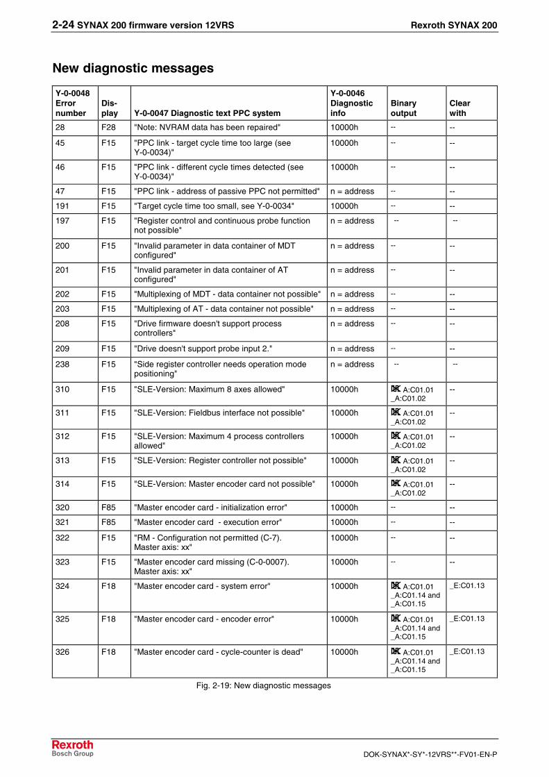
New diagnostic messages
Y-0-0048Errornumber
Dis-play Y-0-0047 Diagnostic text PPC system
Y-0-0046Diagnosticinfo
Binaryoutput
Clearwith
28 F28 "Note: NVRAM data has been repaired" 10000h -- --
45 F15 "PPC link - target cycle time too large (seeY-0-0034)"
10000h -- --
46 F15 "PPC link - different cycle times detected (seeY-0-0034)"
10000h -- --
47 F15 "PPC link - address of passive PPC not permitted" n = address -- --
191 F15 "Target cycle time too small, see Y-0-0034" 10000h -- --
197 F15 "Register control and continuous probe functionnot possible"
n = address -- --
200 F15 "Invalid parameter in data container of MDTconfigured"
n = address -- --
201 F15 "Invalid parameter in data container of ATconfigured"
n = address -- --
202 F15 "Multiplexing of MDT - data container not possible" n = address -- --
203 F15 "Multiplexing of AT - data container not possible" n = address -- --
208 F15 "Drive firmware doesn't support processcontrollers"
n = address -- --
209 F15 "Drive doesn't support probe input 2." n = address -- --
238 F15 "Side register controller needs operation modepositioning"
n = address -- --
310 F15 "SLE-Version: Maximum 8 axes allowed" 10000h A:C01.01_A:C01.02
--
311 F15 "SLE-Version: Fieldbus interface not possible" 10000h A:C01.01_A:C01.02
--
312 F15 "SLE-Version: Maximum 4 process controllersallowed"
10000h A:C01.01_A:C01.02
--
313 F15 "SLE-Version: Register controller not possible" 10000h A:C01.01_A:C01.02
--
314 F15 "SLE-Version: Master encoder card not possible" 10000h A:C01.01_A:C01.02
--
320 F85 "Master encoder card - initialization error" 10000h -- --
321 F85 "Master encoder card - execution error" 10000h -- --
322 F15 "RM - Configuration not permitted (C-7).Master axis: xx"
10000h -- --
323 F15 "Master encoder card missing (C-0-0007).Master axis: xx"
10000h -- --
324 F18 "Master encoder card - system error" 10000h A:C01.01_A:C01.14 and_A:C01.15
_E:C01.13
325 F18 "Master encoder card - encoder error" 10000h A:C01.01_A:C01.14 and_A:C01.15
_E:C01.13
326 F18 "Master encoder card - cycle-counter is dead" 10000h A:C01.01_A:C01.14 and_A:C01.15
_E:C01.13
Fig. 2-19: New diagnostic messages

Rexroth SYNAX 200 SYNAX 200 firmware version 12VRS 2-25
DOK-SYNAX*-SY*-12VRS**-FV01-EN-P
2.6 Changed and extended functions
Register controller• The number of the max. possible register controllers is increased to
16.
• The correction window is now also possible for indirect correction.
• New controlled variables group command value 1 and 2.
Tension controller with load cellThe binary input process controller "pause" is now also supported by thetension controller with load cell.
Fieldbus communicationThe telegram length for the cyclical process data channel by
• Ethernet
• Profibus
• DeviceNet
was enlarged from 32 words up to 64 words.
In addition, the cyclical process data channel may be active in all Sercoscommunication phases (phase 0 .. 4) if it is configured in parameter Y-0-0129 „Fieldbus – control bits“ .
For Y-Parameter, C-Parameter it is then active in all Sercos phases.
For A-Parameter, S/P-Parameter it is always active from Sercos phase 4.
The fieldbus interfaces
• Interbus-S
• ControlNet
are no longer supported.

2-26 SYNAX 200 firmware version 12VRS Rexroth SYNAX 200
DOK-SYNAX*-SY*-12VRS**-FV01-EN-P
2.7 Changed and extended parameters, I/Os and diagnostics
Changed Y parameters
ID no. Name of parameters
Y-0-0016 Integrated PLC configuration
Y-0-0040 Analogue channels - select target parameters
Y-0-0102 PPC-link - control word
Y-0-0106 Internal I/O: PPC outputs 2, output bits 1...32
Y-0-0126 Operation time counter
Y-0-0127 Fieldbus/Ethernet 1 Configuration list of process input data
Y-0-0128 Fieldbus/Ethernet 1 Configuration list of process output data
Y-0-0129 Fieldbus - control bits
Y-0-0164 Command store motion-control-parameters in FW-module
Y-0-0181 Internal I/O: PPC outputs 3, output bits 1...32
Y-0-0182 Internal I/O: PPC outputs 4, output bits 1...32
Y-0-0183 Internal I/O: PPC outputs 5, output bits 1...32
Y-0-0184 Internal I/O: PPC outputs 6, output bits 1...32
Y-0-0185 Ethernet 2 Configuration list of process output data
Y-0-0186 Ethernet 3 Configuration list of process output data
Y-0-0187 Ethernet 4 Configuration list of process output data
Y-0-0188 Ethernet 2 Configuration list of process input data
Y-0-0189 Ethernet 3 Configuration list of process input data
Y-0-0190 Ethernet 4 Configuration list of process input data
Y-0-0191 PPC - IP address
Y-0-0200 -Y-0-0231
Fieldbus - External IO, PPC input word 1 - 32
Y-0-0250 -Y-0-0281
Fieldbus - External IO, PPC output word 1 - 32
Y-0-0300 -Y-0-0363
Fieldbus - PLC input variable data container 1 (Y363 = 64)
Y-0-0531 PPC - Configured options
Fig. 2-20: Changed Y parameters
Y-0-0016 Integrated PLC configurationBits 9 and 10 were added.
Y-0-0040 Analogue channels - select target parametersPermissible entries were added.
Y-0-0102 PPC-link - control wordBit 5 (participant structure) was added.
List of changedY parameters
Individual Y parameter changes

Rexroth SYNAX 200 SYNAX 200 firmware version 12VRS 2-27
DOK-SYNAX*-SY*-12VRS**-FV01-EN-P
Y-0-0106 Internal I/O: PPC outputs 2, output bits 1...32The text has been changed.
Y-0-0126 Operation time counterThe weighting/unit has been changed to 10^4 h. The storage type hasbeen changed from nvRAM to RAM.
Y-0-0127 Fieldbus/Ethernet 1 Configuration list ofprocess input dataThe maximum length was changed from 2048 byte to 4096 byte.
Y-0-0128 Fieldbus/Ethernet 1 Configuration list ofprocess output dataThe maximum length was changed from 2048 byte to 4096 byte.
Y-0-0129 Fieldbus - control bitsBit 28 was added. Default values for the SY version (Motion only) and forthe SL version (MotionLogic) were added.
Y-0-0164 Command store motion-control-parameters inFW-moduleText was added. Access "Write protected in operating mode" has beenchanged to "No write protection".
Y-0-0181 Internal I/O: PPC outputs 3, output bits 1...32Number of the link participants has been changed from 32 to 64.Examples have been changed.
Y-0-0182 Internal I/O: PPC outputs 4, output bits 1...32Number of the link participants has been changed from 32 to 64.Examples have been changed.
Y-0-0183 Internal I/O: PPC outputs 5, output bits 1...32Number of the link participants has been changed from 32 to 64.Examples have been changed.
Y-0-0184 Internal I/O: PPC outputs 6, output bits 1...32Number of the link participants has been changed from 32 to 64.Examples have been changed.
Y-0-0185 Ethernet 2 Configuration list of process outputdataThe maximum length was changed from 2048 byte to 4096 byte.

2-28 SYNAX 200 firmware version 12VRS Rexroth SYNAX 200
DOK-SYNAX*-SY*-12VRS**-FV01-EN-P
Y-0-0186 Ethernet 3 Configuration list of process outputdataThe maximum length was changed from 2048 byte to 4096 byte.
Y-0-0187 Ethernet 4 Configuration list of process outputdataThe maximum length was changed from 2048 byte to 4096 byte.
Y-0-0188 Ethernet 2 Configuration list of process inputdataThe maximum length was changed from 2048 byte to 4096 byte.
Y-0-0189 Ethernet 3 Configuration list of process inputdataThe maximum length was changed from 2048 byte to 4096 byte.
Y-0-0190 Ethernet 4 Configuration list of process inputdataThe maximum length was changed from 2048 byte to 4096 byte.
Y-0-0191 PPC - IP addressThe default value was corrected from 192.168.010.001 to192.168.001.001.
Y-0-0200 - Y-0-0231 Fieldbus - External IO, PPC inputword 1 - 32The memory was changed from FLASH to nvRAM.
Y-0-0250 - Y-0-0281 Fieldbus - External IO, PPC outputword 1 - 32The memory was changed from FLASH to RAM.
Y-0-0300 - Y-0-0363 Fieldbus - PLC input variable datacontainer 1 (Y363 = 64)The memory was changed from RAM to nvRAM.
Y-0-0531 PPC - configured optionsBits 2, 8, 9 and 10 were added.

Rexroth SYNAX 200 SYNAX 200 firmware version 12VRS 2-29
DOK-SYNAX*-SY*-12VRS**-FV01-EN-P
Changed C parameters
ID no. Name of parameters
C-0-0007 RM - control word
C-0-0013 Step width: phase offset, gear input
C-0-0014 Step width: phase offset, gear output
C-0-0081 Phase offset adjusting speed, gear input
C-0-0097 Phase offset adjusting speed, gear output
Fig. 2-21: Changed C parameters
C-0-0007 RM - control wordBits 8, 9, 10 and 11 were added.
C-0-0013 Step width: phase offset, gear inputThe maximum input value has been changed from 10.0000 degree to40.0000 degree.
C-0-0014 Step width: phase offset, gear outputThe maximum input value has been changed from 10.0000 degree to40.0000 degree.
C-0-0081 Phase offset adjusting speed, gear inputThe minimum input value has been changed from 0 to 0.05.
C-0-0097 Phase offset adjusting speed, gear outputThe minimum input value has been changed from 0 to 0.05.
Changed A parameters
ID no. Name of parameters
A-0-0001 Axis type
A-0-0003 Synchronization mode
A-0-0025 Process control - control word 1
A-0-0030 Process controller - proportional gain 1
A-0-0051 Configuration list signal status word (IndraDrive)
A-0-0052 Assign list signal status word (IndraDrive)
A-0-0053 Configuration list signal control word (IndraDrive)
A-0-0054 Assign list signal control word (IndraDrive)
A-0-0107 Register control - target parameter selection
A-0-0132 Group command value additive 1
A-0-0146 Process control - control word 2
A-0-0155 Group command value additive 2
Fig. 2-22: Changed A parameters
List of changedC parameters
Individual C parameter changes
List of changedA parameters

2-30 SYNAX 200 firmware version 12VRS Rexroth SYNAX 200
DOK-SYNAX*-SY*-12VRS**-FV01-EN-P
A-0-0001 Axis typeBit 8 was added.
A-0-0003 Synchronization modeBit combination "Electronic profile of motion" (bit 11, 12) was added.
A-0-0025 Process control - control word 1The default value was changed from 0x0000 0000 to 0xC000 0000.
A-0-0030 Process controller - proportional gain 1The weighting was changed from 0,0001 to 0.000001. The default valuewas changed from 0.0000 to 0.000000.
A-0-0051 Configuration list signal status word(IndraDrive)The name was changed.
A-0-0052 Assign list signal status word (IndraDrive)The name was changed.
A-0-0053 Configuration list signal control word(IndraDrive)The name was changed.
A-0-0054 Assign list signal control word (IndraDrive)The name was changed.
A-0-0107 Register control - target parameter selectionThe bit combination "Select target parameters with direct correction" (bit0, 1, 2) was expanded by bit 3. The bit combination "Select targetparameters with indirect correction" (bit 8, 9, 10) was expanded by bit 11.
A-0-0132 Group command value additive 1The text has been changed.
A-0-0146 Process control - control word 2The default value was changed from 0x0000 0000 to 0x0000 1000.
A-0-0155 Group command value additive 2The text has been changed.
Individual A parameter changes
Rexroth SYNAX 200 SYNAX 200 firmware version 12VRS 2-31
DOK-SYNAX*-SY*-12VRS**-FV01-EN-P
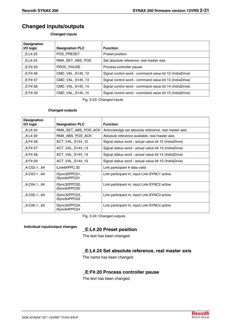
Changed inputs/outputs
DesignationI/O logic Designation PLC Function
_E:L#.20 POS_PRESET Preset position
_E:L#.24 RMA_SET_ABS_POS Set absolute reference, real master axis
_E:F#.20 PROC_PAUSE Process controller pause
_E:F#.56 CMD_VAL_S145_12 Signal control word - command value bit 12 (IndraDrive)
_E:F#.57 CMD_VAL_S145_13 Signal control word - command value bit 13 (IndraDrive)
_E:F#.58 CMD_VAL_S145_14 Signal control word - command value bit 14 (IndraDrive)
_E:F#.59 CMD_VAL_S145_15 Signal control word - command value bit 15 (IndraDrive)
Fig. 2-23: Changed inputs
DesignationI/O logic Designation PLC Function
_A:L#.24 RMA_SET_ABS_POS_ACK Acknowledge set absolute reference, real master axis
_A:L#.39 RMA_ABS_POS_ACK Absolute reference available, real master axis
_A:F#.56 ACT_VAL_S144_12 Signal status word - actual value bit 12 (IndraDrive)
_A:F#.57 ACT_VAL_S144_13 Signal status word - actual value bit 13 (IndraDrive)
_A:F#.58 ACT_VAL_S144_14 Signal status word - actual value bit 14 (IndraDrive)
_A:F#.59 ACT_VAL_S144_15 Signal status word - actual value bit 15 (IndraDrive)
_A:C02.1...64 iLink64PPC.32 Link participant # data valid
_A:C03.1...64 iSync32PPC01,iSync64PPC01
Link participant m, input Link-SYNC1 active
_A:C04.1...64 iSync32PPC02,iSync64PPC02
Link participant m, input Link-SYNC2 active
_A:C05.1...64 iSync32PPC03,iSync64PPC03
Link participant m, input Link-SYNC3 active
_A:C06.1...64 iSync32PPC04,iSync64PPC04
Link participant m, input Link-SYNC4 active
Fig. 2-24: Changed outputs
_E:L#.20 Preset positionThe text has been changed.
_E:L#.24 Set absolute reference, real master axisThe name has been changed.
_E:F#.20 Process controller pauseThe text has been changed.
Changed inputs
Changed outputs
Individual input/output changes
2-32 SYNAX 200 firmware version 12VRS Rexroth SYNAX 200
DOK-SYNAX*-SY*-12VRS**-FV01-EN-P
_E:F#.56 Signal control word - command value bit 12(IndraDrive)The name has been changed.
_E:F#.57 Signal control word - command value bit 13(IndraDrive)The name has been changed.
_E:F#.58 Signal control word - command value bit 14(IndraDrive)The name has been changed.
_E:F#.59 Signal control word - command value bit 14(IndraDrive)The name has been changed.
_A:L#.24 Acknowledge set absolute reference, realmaster axisThe name has been changed.
_A:L#.39 Absolute reference available, real master axisThe name has been changed.
_A:F#.56 Signal status word - actual value bit 12(IndraDrive)The name has been changed.
_A:F#.57 Signal status word - actual value bit 13(IndraDrive)The name has been changed.
_A:F#.58 Signal status word - actual value bit 14(IndraDrive)The name has been changed.
_A:F#.59 Signal status word - actual value bit 15(IndraDrive)The name has been changed.
_A:C02.1...64 Link participant # data validNumber of the link participants has been changed from 32 to 64. Textwas added.
_A:C03.1...64 Link participant m, input Link-SYNC1activeNumber of the link participants has been changed from 32 to 64. Textwas added.

Rexroth SYNAX 200 SYNAX 200 firmware version 12VRS 2-33
DOK-SYNAX*-SY*-12VRS**-FV01-EN-P
_A:C04.1...64 Link participant m, input Link-SYNC2activeNumber of the link participants has been changed from 32 to 64. Textwas added.
_A:C05.1...64 Link participant m, input Link-SYNC3activeNumber of the link participants has been changed from 32 to 64. Textwas added.
_A:C06.1...64 Link participant m, input Link-SYNC4activeNumber of the link participants has been changed from 32 to 64. Textwas added.
Changed diagnostic messages
Y-0-0048Errornumber
Dis-play Y-0-0047 Diagnostic text PPC system
Y-0-0046Diagnosticinfo
Binaryoutput
Clearwith
23 F23 "PPC hardware changed -> NVRAM parametersfrom CF loaded!"
10000h -- --
Fig. 2-25: Changed diagnostic messages
F23 (23) PPC hardware changed -> NVRAM parametersfrom CF loaded!The name has been changed. The text has been changed.
2.8 Phase out of functions / hardware
Following hardware is no longer supported by the SYNAX 12V01:
1. PPC-R01.2 (small, 1 RECO-Slot, 1 expansion card)
2. PPC-R02.2 (wide, 2 RECO-Slots, up to 3 expansion cards)
3. Fieldbus communication
The fieldbus interfaces
• Interbus-S
• ControlNet
are no longer supported.
Individual diagnostic messagechanges

2-34 SYNAX 200 firmware version 12VRS Rexroth SYNAX 200
DOK-SYNAX*-SY*-12VRS**-FV01-EN-P

Rexroth SYNAX 200 Service & Support 3-1
DOK-SYNAX*-SY*-12VRS**-FV01-EN-P
3 Service & Support
3.1 Helpdesk
Unser Kundendienst-Helpdesk im Hauptwerk Lohram Main steht Ihnen mit Rat und Tat zur Seite.Sie erreichen uns
Our service helpdesk at our headquarters in Lohr amMain, Germany can assist you in all kinds of inquiries.Contact us
- telefonisch - by phone: +49 (0) 9352 40 50 60über Service Call Entry Center Mo-Fr 07:00-18:00- via Service Call Entry Center Mo-Fr 7:00 am - 6:00 pm
- per Fax - by fax: +49 (0) 9352 40 49 41
- per e-Mail - by e-mail: [email protected]
3.2 Service-Hotline
Außerhalb der Helpdesk-Zeiten ist der Servicedirekt ansprechbar unter
After helpdesk hours, contact our servicedepartment directly at
+49 (0) 171 333 88 26
oder - or +49 (0) 172 660 04 06
3.3 Internet
Unter www.boschrexroth.com finden Sieergänzende Hinweise zu Service, Reparatur undTraining sowie die aktuellen Adressen *) unsererauf den folgenden Seiten aufgeführten Vertriebs-und Servicebüros.
Verkaufsniederlassungen
Niederlassungen mit Kundendienst
Außerhalb Deutschlands nehmen Sie bitte zuerst Kontakt mitunserem für Sie nächstgelegenen Ansprechpartner auf.
*) Die Angaben in der vorliegenden Dokumentation könnenseit Drucklegung überholt sein.
At www.boschrexroth.com you may findadditional notes about service, repairs and trainingin the Internet, as well as the actual addresses *) ofour sales- and service facilities figuring on thefollowing pages.
sales agencies
offices providing service
Please contact our sales / service office in your area first.
*) Data in the present documentation may have becomeobsolete since printing.
3.4 Vor der Kontaktaufnahme... - Before contacting us...
Wir können Ihnen schnell und effizient helfen wennSie folgende Informationen bereithalten:
1. detaillierte Beschreibung der Störung und derUmstände.
2. Angaben auf dem Typenschild der betreffendenProdukte, insbesondere Typenschlüssel undSeriennummern.
3. Tel.-/Faxnummern und e-Mail-Adresse, unterdenen Sie für Rückfragen zu erreichen sind.
For quick and efficient help, please have thefollowing information ready:
1. Detailed description of the failure andcircumstances.
2. Information on the type plate of the affectedproducts, especially type codes and serialnumbers.
3. Your phone/fax numbers and e-mail address,so we can contact you in case of questions.

3-2 Service & Support Rexroth SYNAX 200
DOK-SYNAX*-SY*-12VRS**-FV01-EN-P
3.5 Kundenbetreuungsstellen - Sales & Service Facilities
Deutschland – Germany vom Ausland: (0) nach Landeskennziffer weglassen!from abroad: don’t dial (0) after country code!
Vertriebsgebiet MitteGermany Centre
Rexroth Indramat GmbHBgm.-Dr.-Nebel-Str. 2 / Postf. 135797816 Lohr am Main / 97803 Lohr
Kompetenz-Zentrum Europa
Tel.: +49 (0)9352 40-0Fax: +49 (0)9352 40-4885
S E R V I C E A U T O M A T I O N
C A L L E N T R Y C E N T E RH e l p d e s kMO – FR
von 07:00 - 18:00 Uhrfrom 7 am – 6 pm
Tel. +49 (0) 9352 40 50 60Fax +49 (0) 9352 40 49 41
S E R V I C E A U T O M A T I O N
H OTLIN E 24 / 7 / 365
außerhalb der Helpdesk-Zeitout of helpdesk hours
Tel.: +49 (0)172 660 04 06o d e r / o r
Tel.: +49 (0)171 333 88 26
S E R V I C E A U T O M A T I O N
ERSATZTEILE / SPARESverlängerte Ansprechzeit- extended office time -
♦ nur an Werktagen- only on working days -
♦ von 07:00 - 18:00 Uhr- from 7 am - 6 pm -
Tel. +49 (0) 9352 40 42 22
Vertriebsgebiet SüdGermany South
Bosch Rexroth AGLandshuter Allee 8-1080637 München
Tel.: +49 (0)89 127 14-0Fax: +49 (0)89 127 14-490
Vertriebsgebiet WestGermany West
Bosch Rexroth AGRegionalzentrum WestBorsigstrasse 1540880 Ratingen
Tel.: +49 (0)2102 409-0Fax: +49 (0)2102 409-406
+49 (0)2102 409-430
Gebiet SüdwestGermany South-West
Bosch Rexroth AGService-Regionalzentrum Süd-WestSiemensstr.170736 Fellbach
Tel.: +49 (0)711 51046–0Fax: +49 (0)711 51046–248
Vertriebsgebiet NordGermany North
Bosch Rexroth AGWalsroder Str. 9330853 Langenhagen
Tel.: +49 (0) 511 72 66 57-0Service: +49 (0) 511 72 66 57-256Fax: +49 (0) 511 72 66 57-93Service: +49 (0) 511 72 66 57-783
Vertriebsgebiet MitteGermany Centre
Bosch Rexroth AGRegionalzentrum MitteWaldecker Straße 1364546 Mörfelden-Walldorf
Tel.: +49 (0) 61 05 702-3Fax: +49 (0) 61 05 702-444
Vertriebsgebiet OstGermany East
Bosch Rexroth AGBeckerstraße 3109120 Chemnitz
Tel.: +49 (0)371 35 55-0Fax: +49 (0)371 35 55-333
Vertriebsgebiet OstGermany East
Bosch Rexroth AGRegionalzentrum OstWalter-Köhn-Str. 4d04356 Leipzig
Tel.: +49 (0)341 25 61-0Fax: +49 (0)341 25 61-111

Rexroth SYNAX 200 Service & Support 3-3
DOK-SYNAX*-SY*-12VRS**-FV01-EN-P
Europa (West) - Europe (West)
vom Ausland: (0) nach Landeskennziffer weglassen, Italien: 0 nach Landeskennziffer mitwählenfrom abroad: don’t dial (0) after country code, Italy: dial 0 after country code
Austria - Österreich
Bosch Rexroth GmbHElectric Drives & ControlsStachegasse 131120 Wien
Tel.: +43 (0)1 985 25 40Fax: +43 (0)1 985 25 40-93
Austria – Österreich
Bosch Rexroth GmbHElectric Drives & ControlsIndustriepark 184061 Pasching
Tel.: +43 (0)7221 605-0Fax: +43 (0)7221 605-21
Belgium - Belgien
Bosch Rexroth NV/SAHenri Genessestraat 11070 Bruxelles
Tel: +32 (0) 2 451 26 08Fax: +32 (0) 2 451 27 [email protected]@boschrexroth.be
Denmark - Dänemark
BEC A/SZinkvej 68900 Randers
Tel.: +45 (0)87 11 90 60Fax: +45 (0)87 11 90 61
Great Britain – Großbritannien
Bosch Rexroth Ltd.Electric Drives & ControlsBroadway Lane, South CerneyCirencester, Glos GL7 5UH
Tel.: +44 (0)1285 863000Fax: +44 (0)1285 [email protected]@boschrexroth.co.uk
Finland - Finnland
Bosch Rexroth OyElectric Drives & ControlsAnsatie 6017 40 Vantaa
Tel.: +358 (0)9 84 91-11Fax: +358 (0)9 84 91-13 60
France - Frankreich
Bosch Rexroth SASElectric Drives & ControlsAvenue de la Trentaine(BP. 74)77503 Chelles Cedex
Tel.: +33 (0)164 72-63 22Fax: +33 (0)164 72-63 20Hotline: +33 (0)608 33 43 28
France - Frankreich
Bosch Rexroth SASElectric Drives & ControlsZI de Thibaud, 20 bd. Thibaud(BP. 1751)31084 Toulouse
Tel.: +33 (0)5 61 43 61 87Fax: +33 (0)5 61 43 94 12
France – Frankreich
Bosch Rexroth SASElectric Drives & Controls91, Bd. Irène Joliot-Curie69634 Vénissieux – Cedex
Tel.: +33 (0)4 78 78 53 65Fax: +33 (0)4 78 78 53 62
Italy - Italien
Bosch Rexroth S.p.A.Via G. Di Vittorio, 120063 Cernusco S/N.MI
Hotline: +39 02 92 365 563Tel.: +39 02 92 365 1Service: +39 02 92 365 300Fax: +39 02 92 365 500Service: +39 02 92 365 516
Italy - Italien
Bosch Rexroth S.p.A.Via Paolo Veronesi, 25010148 Torino
Tel.: +39 011 224 88 11Fax: +39 011 224 88 30
Italy - Italien
Bosch Rexroth S.p.A.Via Mascia, 180053 Castellamare di Stabia NA
Tel.: +39 081 8 71 57 00Fax: +39 081 8 71 68 85
Italy - Italien
Bosch Rexroth S.p.A.Via del Progresso, 16 (Zona Ind.)35020 Padova
Tel.: +39 049 8 70 13 70Fax: +39 049 8 70 13 77
Italy - Italien
Bosch Rexroth S.p.A.Via Isonzo, 6140033 Casalecchio di Reno (Bo)
Tel.: +39 051 29 86 430Fax: +39 051 29 86 490
Netherlands - Niederlande/Holland
Bosch Rexroth Services B.V.Technical ServicesKruisbroeksestraat 1(P.O. Box 32)5281 RV Boxtel
Tel.: +31 (0) 411 65 16 40+31 (0) 411 65 17 27
Fax: +31 (0) 411 67 78 14+31 (0) 411 68 28 60
Netherlands – Niederlande/Holland
Bosch Rexroth B.V.Kruisbroeksestraat 1(P.O. Box 32)5281 RV Boxtel
Tel.: +31 (0) 411 65 19 51Fax: +31 (0) 411 65 14 83www.boschrexroth.nl
Norway - Norwegen
Bosch Rexroth ASElectric Drives & ControlsBerghagan 1 or: Box 30071405 Ski-Langhus 1402 Ski
Tel.: +47 (0) 64 86 41 00
Fax: +47 (0) 64 86 90 62
Hotline: +47 (0)64 86 94 [email protected]
Spain - Spanien
Bosch Rexroth S.A.Electric Drives & ControlsCentro Industrial SantigaObradors s/n08130 Santa Perpetua de MogodaBarcelona
Tel.: +34 9 37 47 94 00Fax: +34 9 37 47 94 01
Spain – Spanien
Goimendi S.A.Electric Drives & ControlsParque Empresarial ZuatzuC/ Francisco Grandmontagne no.220018 San Sebastian
Tel.: +34 9 43 31 84 21- service: +34 9 43 31 84 56Fax: +34 9 43 31 84 27- service: +34 9 43 31 84 [email protected]
Sweden - Schweden
Bosch Rexroth ABElectric Drives & Controls- Varuvägen 7(Service: Konsumentvägen 4, Älfsjö)125 81 Stockholm
Tel.: +46 (0)8 727 92 00Fax: +46 (0)8 647 32 77
Sweden - Schweden
Bosch Rexroth ABElectric Drives & ControlsEkvändan 7254 67 Helsingborg
Tel.: +46 (0) 42 38 88 -50Fax: +46 (0) 42 38 88 -74
Switzerland East - Schweiz Ost
Bosch Rexroth Schweiz AGElectric Drives & ControlsHemrietstrasse 28863 ButtikonTel. +41 (0) 55 46 46 111Fax +41 (0) 55 46 46 222
Switzerland West - Schweiz West
Bosch Rexroth Suisse SAAv. Général Guisan 261800 Vevey 1
Tel.: +41 (0)21 632 84 20Fax: +41 (0)21 632 84 21

3-4 Service & Support Rexroth SYNAX 200
DOK-SYNAX*-SY*-12VRS**-FV01-EN-P
Europa (Ost) - Europe (East)
vom Ausland: (0) nach Landeskennziffer weglassenfrom abroad: don’t dial (0) after country code
Czech Republic - Tschechien
Bosch -Rexroth, spol.s.r.o.Hviezdoslavova 5627 00 Brno
Tel.: +420 (0)5 48 126 358Fax: +420 (0)5 48 126 112
Czech Republic - Tschechien
DEL a.s.Strojírenská 38591 01 Zdar nad SázavouTel.: +420 566 64 3144Fax: +420 566 62 1657
Hungary - Ungarn
Bosch Rexroth Kft.Angol utca 341149 Budapest
Tel.: +36 (1) 422 3200Fax: +36 (1) 422 3201
Poland – Polen
Bosch Rexroth Sp.zo.o.ul. Staszica 105-800 Pruszków
Tel.: +48 22 738 18 00– service: +48 22 738 18 46Fax: +48 22 758 87 35– service: +48 22 738 18 42
Poland – Polen
Bosch Rexroth Sp.zo.o.Biuro Poznanul. Dabrowskiego 81/8560-529 Poznan
Tel.: +48 061 847 64 62 /-63Fax: +48 061 847 64 02
Romania - Rumänien
East Electric S.R.L.Bdul Basarabia no.250, sector 373429 Bucuresti
Tel./Fax:: +40 (0)21 255 35 07+40 (0)21 255 77 13
Fax: +40 (0)21 725 61 [email protected]
Romania - Rumänien
Bosch Rexroth Sp.zo.o.Str. Drobety nr. 4-10, app. 1470258 Bucuresti, Sector 2
Tel.: +40 (0)1 210 48 25+40 (0)1 210 29 50
Fax: +40 (0)1 210 29 52
Russia - Russland
Bosch Rexroth OOOWjatskaja ul. 27/15127015 Moskau
Tel.: +7-095-785 74 78+7-095 785 74 79
Fax: +7 095 785 74 [email protected]
Russia Belarus - Weissrussland
ELMIS10, Internationalnaya246640 Gomel, Belarus
Tel.: +375/ 232 53 42 70+375/ 232 53 21 69
Fax: +375/ 232 53 37 [email protected]
Turkey - Türkei
Bosch Rexroth OtomasyonSan & Tic. A..S.Fevzi Cakmak Cad No. 334630 Sefaköy Istanbul
Tel.: +90 212 413 34 00Fax: +90 212 413 34 17www.boschrexroth.com.tr
Turkey - Türkei
Servo Kontrol Ltd. Sti.Perpa Ticaret Merkezi B BlokKat: 11 No: 160980270 Okmeydani-Istanbul
Tel: +90 212 320 30 80Fax: +90 212 320 30 [email protected]
Slowenia - Slowenien
DOMELOtoki 2164 228 Zelezniki
Tel.: +386 5 5117 152Fax: +386 5 5117 [email protected]

Rexroth SYNAX 200 Service & Support 3-5
DOK-SYNAX*-SY*-12VRS**-FV01-EN-P
Africa, Asia, Australia – incl. Pacific Rim
Australia - Australien
AIMS - Australian IndustrialMachinery Services Pty. Ltd.28 Westside DriveLaverton North Vic 3026Melbourne
Tel.: +61 3 93 14 3321Fax: +61 3 93 14 3329Hotlines: +61 3 93 14 3321
+61 4 19 369 [email protected]
Australia - Australien
Bosch Rexroth Pty. Ltd.No. 7, Endeavour WayBraeside Victoria, 31 95Melbourne
Tel.: +61 3 95 80 39 33Fax: +61 3 95 80 17 [email protected]
China
Shanghai Bosch RexrothHydraulics & Automation Ltd.Waigaoqiao, Free Trade ZoneNo.122, Fu Te Dong Yi RoadShanghai 200131 - P.R.China
Tel.: +86 21 58 66 30 30Fax: +86 21 58 66 55 [email protected][email protected]
China
Shanghai Bosch RexrothHydraulics & Automation Ltd.4/f, Marine TowerNo.1, Pudong AvenueShanghai 200120 - P.R.China
Tel: +86 21 68 86 15 88Fax: +86 21 58 40 65 77
China
Bosch Rexroth China Ltd.15/F China World Trade Center1, Jianguomenwai AvenueBeijing 100004, P.R.China
Tel.: +86 10 65 05 03 80Fax: +86 10 65 05 03 79
China
Bosch Rexroth China Ltd.Guangzhou Repres. OfficeRoom 1014-1016, Metro Plaza,Tian He District, 183 Tian He Bei RdGuangzhou 510075, P.R.China
Tel.: +86 20 8755-0030+86 20 8755-0011
Fax: +86 20 8755-2387
China
Bosch Rexroth (China) Ltd.A-5F., 123 Lian Shan StreetSha He Kou DistrictDalian 116 023, P.R.China
Tel.: +86 411 46 78 930Fax: +86 411 46 78 932
China
Melchers GmbHBRC-SE, Tightening & Press-fit13 Floor Est Ocean CentreNo.588 Yanan Rd. East65 Yanan Rd. WestShanghai 200001
Tel.: +86 21 6352 8848Fax: +86 21 6351 3138
Hongkong
Bosch Rexroth (China) Ltd.6th Floor,Yeung Yiu Chung No.6 Ind Bldg.19 Cheung Shun StreetCheung Sha Wan,Kowloon, Hongkong
Tel.: +852 22 62 51 00Fax: +852 27 41 33 44
India - Indien
Bosch Rexroth (India) Ltd.Electric Drives & ControlsPlot. No.96, Phase IIIPeenya Industrial AreaBangalore – 560058
Tel.: +91 80 51 17 0-211...-218Fax: +91 80 83 94 345
+91 80 83 97 374
India - Indien
Bosch Rexroth (India) Ltd.Electric Drives & ControlsAdvance House, II FloorArk Industrial CompoundNarol Naka, Makwana RoadAndheri (East), Mumbai - 400 059
Tel.: +91 22 28 56 32 90+91 22 28 56 33 18
Fax: +91 22 28 56 32 93
India - Indien
Bosch Rexroth (India) Ltd.S-10, Green Park ExtensionNew Delhi – 110016
Tel.: +91 11 26 56 65 25+91 11 26 56 65 27
Fax: +91 11 26 56 68 87
Indonesia - Indonesien
PT. Bosch RexrothBuilding # 202, CilandakCommercial EstateJl. Cilandak KKO, Jakarta 12560
Tel.: +62 21 7891169 (5 lines)Fax: +62 21 7891170 - [email protected]
Japan
Bosch Rexroth Automation Corp.Service Center JapanYutakagaoka 1810, Meito-ku,NAGOYA 465-0035, Japan
Tel.: +81 52 777 88 41+81 52 777 88 53+81 52 777 88 79
Fax: +81 52 777 89 01
Japan
Bosch Rexroth Automation Corp.Electric Drives & Controls2F, I.R. BuildingNakamachidai 4-26-44, Tsuzuki-kuYOKOHAMA 224-0041, Japan
Tel.: +81 45 942 72 10Fax: +81 45 942 03 41
Korea
Bosch Rexroth-Korea Ltd.Electric Drives and ControlsBongwoo Bldg. 7FL, 31-7, 1GaJangchoong-dong, Jung-guSeoul, 100-391
Tel.: +82 234 061 813Fax: +82 222 641 295
Korea
Bosch Rexroth-Korea Ltd.1515-14 Dadae-Dong, Saha-guElectric Drives & ControlsPusan Metropolitan City, 604-050
Tel.: +82 51 26 00 741Fax: +82 51 26 00 [email protected]
Malaysia
Bosch Rexroth Sdn.Bhd.11, Jalan U8/82, Seksyen U840150 Shah AlamSelangor, Malaysia
Tel.: +60 3 78 44 80 00Fax: +60 3 78 45 48 [email protected]@tm.net.my
Singapore - Singapur
Bosch Rexroth Pte Ltd15D Tuas RoadSingapore 638520
Tel.: +65 68 61 87 33Fax: +65 68 61 18 25sanjay.nemade
@boschrexroth.com.sg
South Africa - Südafrika
TECTRA Automation (Pty) Ltd.71 Watt Street, MeadowdaleEdenvale 1609
Tel.: +27 11 971 94 00Fax: +27 11 971 94 40Hotline: +27 82 903 29 [email protected]
Taiwan
Bosch Rexroth Co., Ltd.Taichung Industrial AreaNo.19, 38 RoadTaichung, Taiwan 407, R.O.C.
Tel : +886 - 4 -235 08 383Fax: +886 - 4 -235 08 [email protected]@boschrexroth.com.tw
Taiwan
Bosch Rexroth Co., Ltd.Tainan BranchNo. 17, Alley 24, Lane 737Chung Cheng N.Rd. YungkangTainan Hsien, Taiwan, R.O.C.
Tel : +886 - 6 –253 6565Fax: +886 - 6 –253 [email protected]
Thailand
NC Advance Technology Co. Ltd.59/76 Moo 9Ramintra road 34Tharang, Bangkhen,Bangkok 10230
Tel.: +66 2 943 70 62+66 2 943 71 21
Fax: +66 2 509 23 62Hotline +66 1 984 61 [email protected]
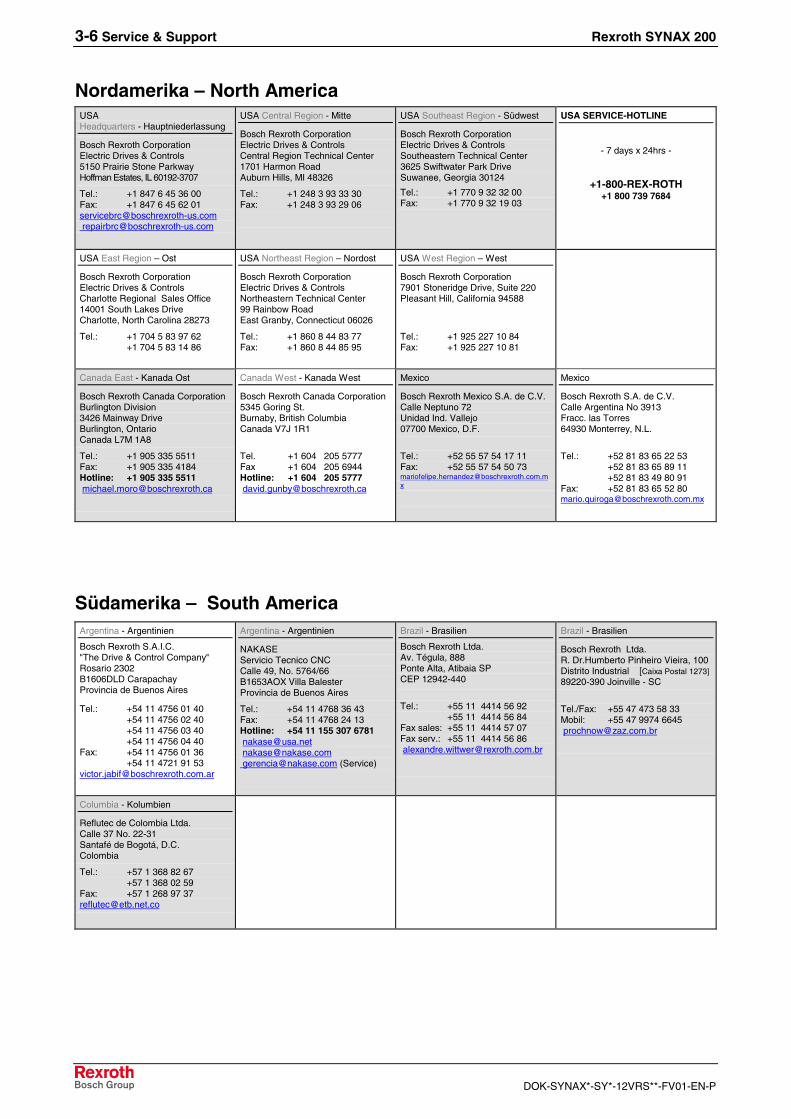
3-6 Service & Support Rexroth SYNAX 200
DOK-SYNAX*-SY*-12VRS**-FV01-EN-P
Nordamerika – North AmericaUSAHeadquarters - Hauptniederlassung
Bosch Rexroth CorporationElectric Drives & Controls5150 Prairie Stone ParkwayHoffman Estates, IL 60192-3707
Tel.: +1 847 6 45 36 00Fax: +1 847 6 45 62 [email protected]@boschrexroth-us.com
USA Central Region - Mitte
Bosch Rexroth CorporationElectric Drives & ControlsCentral Region Technical Center1701 Harmon RoadAuburn Hills, MI 48326
Tel.: +1 248 3 93 33 30Fax: +1 248 3 93 29 06
USA Southeast Region - Südwest
Bosch Rexroth CorporationElectric Drives & ControlsSoutheastern Technical Center3625 Swiftwater Park DriveSuwanee, Georgia 30124
Tel.: +1 770 9 32 32 00Fax: +1 770 9 32 19 03
USA SERVICE-HOTLINE
- 7 days x 24hrs -
+1-800-REX-ROTH+1 800 739 7684
USA East Region – Ost
Bosch Rexroth CorporationElectric Drives & ControlsCharlotte Regional Sales Office14001 South Lakes DriveCharlotte, North Carolina 28273
Tel.: +1 704 5 83 97 62+1 704 5 83 14 86
USA Northeast Region – Nordost
Bosch Rexroth CorporationElectric Drives & ControlsNortheastern Technical Center99 Rainbow RoadEast Granby, Connecticut 06026
Tel.: +1 860 8 44 83 77Fax: +1 860 8 44 85 95
USA West Region – West
Bosch Rexroth Corporation7901 Stoneridge Drive, Suite 220Pleasant Hill, California 94588
Tel.: +1 925 227 10 84Fax: +1 925 227 10 81
Canada East - Kanada Ost
Bosch Rexroth Canada CorporationBurlington Division3426 Mainway DriveBurlington, OntarioCanada L7M 1A8
Tel.: +1 905 335 5511Fax: +1 905 335 4184Hotline: +1 905 335 [email protected]
Canada West - Kanada West
Bosch Rexroth Canada Corporation5345 Goring St.Burnaby, British ColumbiaCanada V7J 1R1
Tel. +1 604 205 5777Fax +1 604 205 6944Hotline: +1 604 205 [email protected]
Mexico
Bosch Rexroth Mexico S.A. de C.V.Calle Neptuno 72Unidad Ind. Vallejo07700 Mexico, D.F.
Tel.: +52 55 57 54 17 11Fax: +52 55 57 54 50 [email protected]
Mexico
Bosch Rexroth S.A. de C.V.Calle Argentina No 3913Fracc. las Torres64930 Monterrey, N.L.
Tel.: +52 81 83 65 22 53+52 81 83 65 89 11+52 81 83 49 80 91
Fax: +52 81 83 65 52 [email protected]
Südamerika – South AmericaArgentina - Argentinien
Bosch Rexroth S.A.I.C."The Drive & Control Company"Rosario 2302B1606DLD CarapachayProvincia de Buenos Aires
Tel.: +54 11 4756 01 40+54 11 4756 02 40+54 11 4756 03 40+54 11 4756 04 40
Fax: +54 11 4756 01 36+54 11 4721 91 53
Argentina - Argentinien
NAKASEServicio Tecnico CNCCalle 49, No. 5764/66B1653AOX Villa BalesterProvincia de Buenos Aires
Tel.: +54 11 4768 36 43Fax: +54 11 4768 24 13Hotline: +54 11 155 307 [email protected]@[email protected] (Service)
Brazil - Brasilien
Bosch Rexroth Ltda.Av. Tégula, 888Ponte Alta, Atibaia SPCEP 12942-440
Tel.: +55 11 4414 56 92+55 11 4414 56 84
Fax sales: +55 11 4414 57 07Fax serv.: +55 11 4414 56 [email protected]
Brazil - Brasilien
Bosch Rexroth Ltda.R. Dr.Humberto Pinheiro Vieira, 100Distrito Industrial [Caixa Postal 1273]89220-390 Joinville - SC
Tel./Fax: +55 47 473 58 33Mobil: +55 47 9974 [email protected]
Columbia - Kolumbien
Reflutec de Colombia Ltda.Calle 37 No. 22-31Santafé de Bogotá, D.C.Colombia
Tel.: +57 1 368 82 67+57 1 368 02 59
Fax: +57 1 268 97 [email protected]

Bosch Rexroth AGElectric Drives and ControlsP.O. Box 13 5797803 Lohr, GermanyBgm.-Dr.-Nebel-Str. 297816 Lohr, GermanyPhone +49 (0)93 52-40-50 60Fax +49 (0)93 52-40-49 [email protected]
Printed in GermanyDOK-SYNAX*-SY*-12VRS**-FV01-EN-PR911307340