Revit Lab 2a
36
Adding Stairs and Railings In this lesson, you add stair and railing objects to the basic building layout. You learn to create a: ■ Multi-story straight stair. ■ Multi-story U-shaped stair. ■ Family type for wall-mounted railings, and apply this type to the U-shaped stair. ■ Guardrail for the balcony over the pavilion. Adding a Straight Stair In this exercise, you add a straight run stair to the project. You then modify it, creating a multi-story stair by adding a stair from the second to the third floor. 10 167
-
Upload
dsunte-wilson -
Category
Documents
-
view
224 -
download
1
description
Revit
Transcript of Revit Lab 2a

Adding Stairs and Railings
In this lesson, you add stair and railing objects to the basic building layout. You learn to create a:
■ Multi-story straight stair.
■ Multi-story U-shaped stair.
■ Family type for wall-mounted railings, and apply this type to the U-shaped stair.
■ Guardrail for the balcony over the pavilion.
Adding a Straight StairIn this exercise, you add a straight run stair to the project. You then modify it, creating a multi-story stairby adding a stair from the second to the third floor.
10
167

Training File
■ Click ➤ Open.
■ In the left pane of the Open dialog, click Training Files, and open Imperial\RAC_SR_01_Straight_Stair_i.rvt.
Create the stair
1 In the Project Browser, under Floor Plans, double-click 01 - Entry Level.
2 Zoom in to the opening in the lower area of the main concourse.
The dashed lines represent the opening in the floor above for the stairs.
3 Click Home tab ➤ Circulation panel ➤ Stairs.
4 Click Create Stairs Sketch tab ➤ Element panel ➤ Stairs Properties.
You verify that the correct stair family type is selected, and then specify the stair width.
5 Specify parameters in the Instance Properties dialog:
■ For Type, verify that 6'' max riser 12'' tread is selected.
■ Under Dimensions, for Width, type 5'4''.
■ Click OK.
6 On the Draw panel, verify that Run is selected.
168 | Chapter 10 Adding Stairs and Railings
When you use the Run option, the risers are drawn according to the calculation rules in thestair type properties. Because you are not yet sure how long the stair should be, you draw thestair at a distance from the opening, and then move it into the correct position.
7 Click to the right of the opening to specify the start point for the stair.
As you draw the run, the dynamic indicator displays the number of risers created and the numberremaining.
8 Move the cursor up to draw 12 risers, and click to specify the endpoint of the stair.
You end the stair so you can create a landing.
9 Move the cursor up until the second guide (horizontal dashed line) displays, and click to beginthe second flight of stairs.
When creating landings, guides help you place the stair run. In this example, you create a landingthe same length as the width of the stair.
10 Move the cursor up until 1 riser is remaining, and click to end the second flight.
You end the flight at this point so that it meets the edge of the floor above. In this example,the floor edge will be used and will count as the final riser.
Adding a Straight Stair | 169

11 Click Modify.
12 Draw a selection box around the stair.
You select the stair and move it into position in the center of the floor opening.
13 Click Create Stairs Sketch tab ➤ Modify panel ➤ Move.
14 Select the top center endpoint of the second flight of stairs.
15 Select the midpoint of the top of the opening to reposition the stair.
170 | Chapter 10 Adding Stairs and Railings

16 Press Esc.
17 Click Create Stairs Sketch tab ➤ Stairs panel ➤ Finish Stairs.
18 Close the warning that displays. (The floor edge will count as the final riser.)
Create a section view
19 Click View tab ➤ Create panel ➤ Section.
20 Click above the stair (at the horizontal midpoint of the stair) to specify the section start point,and click below the stair to specify the endpoint.
Adding a Straight Stair | 171

21 Press Esc.
22 Double-click the section head (at the top of the section line) to open the section view.
Modify the stair object to reach the third floor
23 Select the stair.
24 Click Modify Stairs tab ➤ Element panel ➤ Element Properties drop-down ➤ Instance Properties.
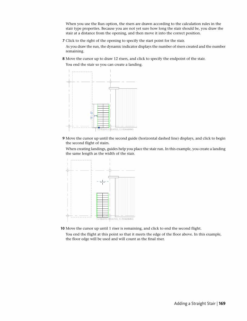
25 In the Instance Properties dialog, for Multistory Top Level, select 03 - Floor, and click OK.
By making a stair multi-story, the geometry of the stair is duplicated as needed to reach thespecified floor.
172 | Chapter 10 Adding Stairs and Railings
26 Press Esc.
27 Close the file with or without saving it.
Adding a U-Shaped StairIn this exercise, you add a U-shaped stair to the project at one of the stair tower locations. You modify thestair from single- to multi-story, and extend it to the third floor.
Adding a U-Shaped Stair | 173

Training File
■ Click ➤ Open.
■ In the left pane of the Open dialog, click Training Files, and open Imperial\RAC_SR_02_U_Stair_i.rvt.
Place the stair
1 In the Project Browser, under Floor Plans, double-click 01 - Entry Level.
2 Zoom in to the stair tower area at the right end of the longer wing of the building.
3 Click Home tab ➤ Circulation panel ➤ Stairs.
4 Click Create Stairs Sketch tab ➤ Element panel ➤ Stairs Properties.
5 Specify values in the Instance Properties dialog:
■ For Type, select 6'' max riser 12'' tread.
■ For Multistory Top Level, select 03 - Floor.You create the stair up to the third floor.
■ Under Dimensions, for Width, type 3'9''.
■ Click OK.
174 | Chapter 10 Adding Stairs and Railings

6 Using the reference planes as a guide, place the stair:
■ Press Tab to highlight the upper-left endpoint of the left reference plane, and click to specifythe first point of the stair run.
■ Move the cursor down, and click the bottom endpoint of the left reference plane.
The first flight of stairs is placed.
■ Using the previous method, and starting at the bottom of the right reference plane, placethe second flight of stairs.Notice that the landing is automatically created, forming a U-shaped stair.
The stair ends with 1 riser remaining because the last riser is the floor edge.
Adding a U-Shaped Stair | 175
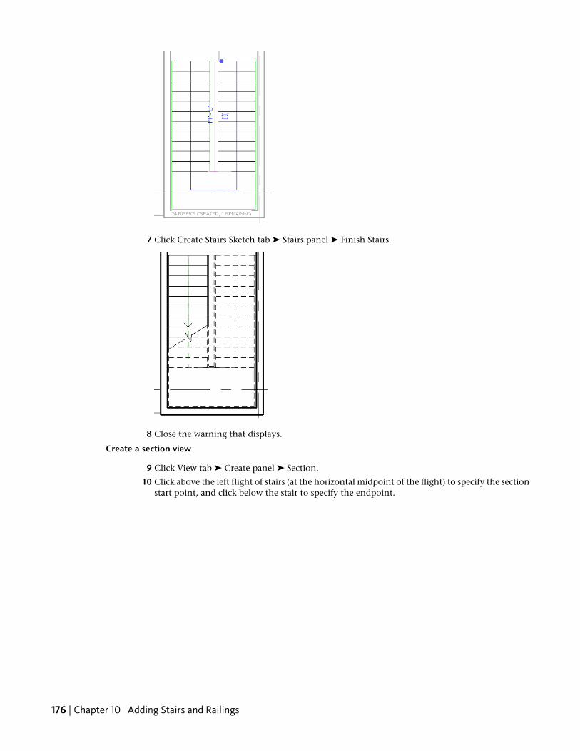
7 Click Create Stairs Sketch tab ➤ Stairs panel ➤ Finish Stairs.
8 Close the warning that displays.
Create a section view
9 Click View tab ➤ Create panel ➤ Section.
10 Click above the left flight of stairs (at the horizontal midpoint of the flight) to specify the sectionstart point, and click below the stair to specify the endpoint.
176 | Chapter 10 Adding Stairs and Railings
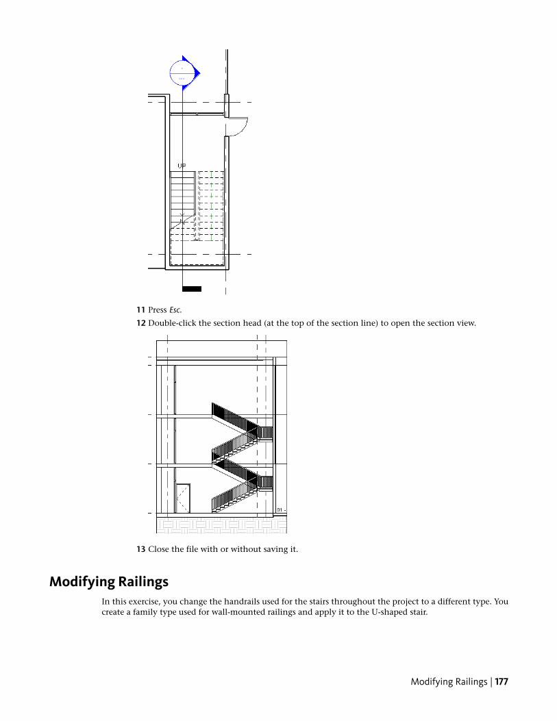
11 Press Esc.
12 Double-click the section head (at the top of the section line) to open the section view.
13 Close the file with or without saving it.
Modifying RailingsIn this exercise, you change the handrails used for the stairs throughout the project to a different type. Youcreate a family type used for wall-mounted railings and apply it to the U-shaped stair.
Modifying Railings | 177
Training File
■ Click ➤ Open.
■ In the left pane of the Open dialog, click Training Files, and openImperial\RAC_SR_03_Modify_Railing_i.rvt.
Create a wall-mounted handrail type
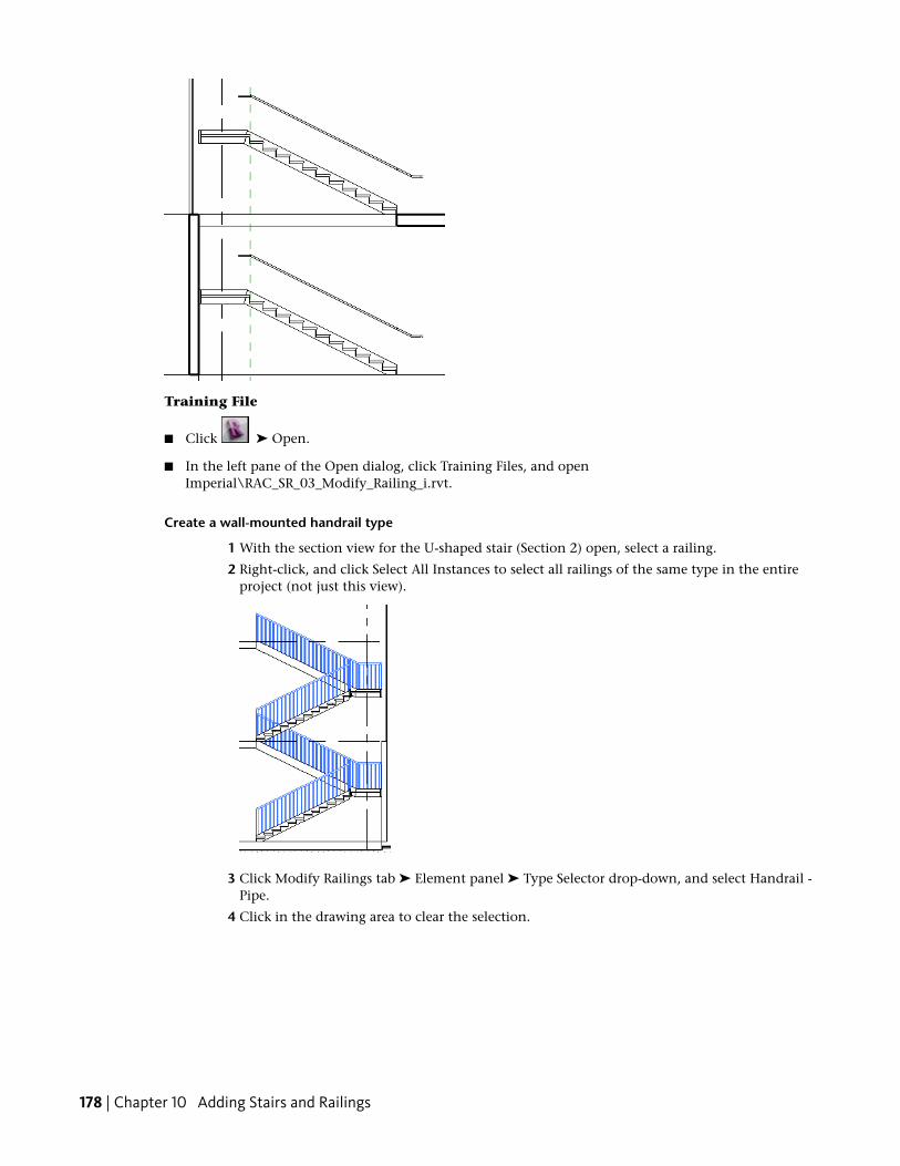
1 With the section view for the U-shaped stair (Section 2) open, select a railing.
2 Right-click, and click Select All Instances to select all railings of the same type in the entireproject (not just this view).
3 Click Modify Railings tab ➤ Element panel ➤ Type Selector drop-down, and select Handrail -Pipe.
4 Click in the drawing area to clear the selection.
178 | Chapter 10 Adding Stairs and Railings
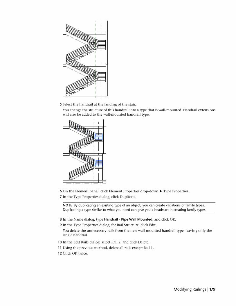
5 Select the handrail at the landing of the stair.
You change the structure of this handrail into a type that is wall-mounted. Handrail extensionswill also be added to the wall-mounted handrail type.
6 On the Element panel, click Element Properties drop-down ➤ Type Properties.
7 In the Type Properties dialog, click Duplicate.
NOTE By duplicating an existing type of an object, you can create variations of family types.Duplicating a type similar to what you need can give you a headstart in creating family types.
8 In the Name dialog, type Handrail - Pipe Wall Mounted, and click OK.
9 In the Type Properties dialog, for Rail Structure, click Edit.
You delete the unnecessary rails from the new wall-mounted handrail type, leaving only thesingle handrail.
10 In the Edit Rails dialog, select Rail 2, and click Delete.
11 Using the previous method, delete all rails except Rail 1.
12 Click OK twice.
Modifying Railings | 179

13 Press Esc.
Load baluster families
14 Click Insert tab ➤ Load from Library panel ➤ Load Family.
You replace the vertical balusters of the railing type with wall brackets and handrail extensions.You load these baluster families into the project to use in the railing type.
15 In the left pane of the Load Family dialog, click Training Files, and navigate to Imperial\Families.
16 Open the following families:
■ Handrail - Bracket.rfa
■ Handrail - Round w Extension - End.rfa
■ Handrail - Round w Extension - Start-Offset.rfa
NOTE While pressing Ctrl, select all 3 families, and load them at the same time.
Replace baluster and post types
17 Select the handrail at the landing of the stair.
18 On the Element panel, click Element Properties drop-down ➤ Type Properties.
19 In the Type Properties dialog, for Baluster Placement, click Edit.
20 Specify types in the Edit Baluster Placement dialog:
■ In the Main pattern section, for the Regular baluster, Baluster Family, select Handrail - Bracket: Handrail - Bracket.The vertical post used through the main body of the rail is replaced with a handrail bracket.
■ In the Posts section, for the Start Post Baluster Family, select Handrail - Round w Extension- Start-Offset : 1 1/2'' Handrail.
■ For the Corner Post Baluster Family, select Handrail - Bracket - Handrail - Bracket.
■ For the End Post Baluster Family, select Handrail - Round w Extension - End : 1 1/2'' Handrail.
The posts placed at the beginning, end, and corners of the railings are replaced with the respectivefamilies that you loaded into the project in the previous steps.
21 Click OK twice.
180 | Chapter 10 Adding Stairs and Railings

Edit the railing
22 In the Project Browser, under Floor Plans, double-click 01 - Entry Level, and zoom in to the stairin the longer wing.
You do not need to run the railing running along the wall around the landing of the stair. Editthe railing so each flight has a single wall-mounted rail.
23 Select the outside railing, and click Modify Railings tab ➤ Edit panel ➤ Edit Path.
24 While pressing Ctrl, select the railing segments on the landing and the left stair flight, and pressDelete.
Railings must be drawn as a single line; therefore, they cannot be placed as broken segments.You create the rail on the left flight of stairs as a separate railing object.
25 Click Modify Railings tab ➤ Railing panel ➤ Finish Railing.
Add a railing to the left stair
26 Click Home tab ➤ Circulation panel ➤ Railing.
27 Select the upper left endpoint of the left stair, and select the lower left endpoint of the stair.
NOTE When selecting the endpoints, make sure to click the interior stringer edge; otherwise, therailing will be created in the wall.
Modifying Railings | 181
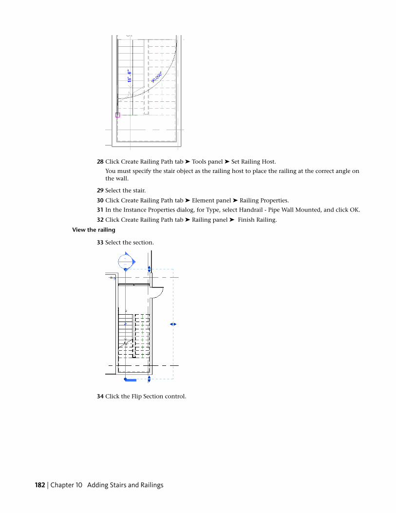
28 Click Create Railing Path tab ➤ Tools panel ➤ Set Railing Host.
You must specify the stair object as the railing host to place the railing at the correct angle onthe wall.
29 Select the stair.
30 Click Create Railing Path tab ➤ Element panel ➤ Railing Properties.
31 In the Instance Properties dialog, for Type, select Handrail - Pipe Wall Mounted, and click OK.
32 Click Create Railing Path tab ➤ Railing panel ➤ Finish Railing.
View the railing
33 Select the section.
34 Click the Flip Section control.
182 | Chapter 10 Adding Stairs and Railings
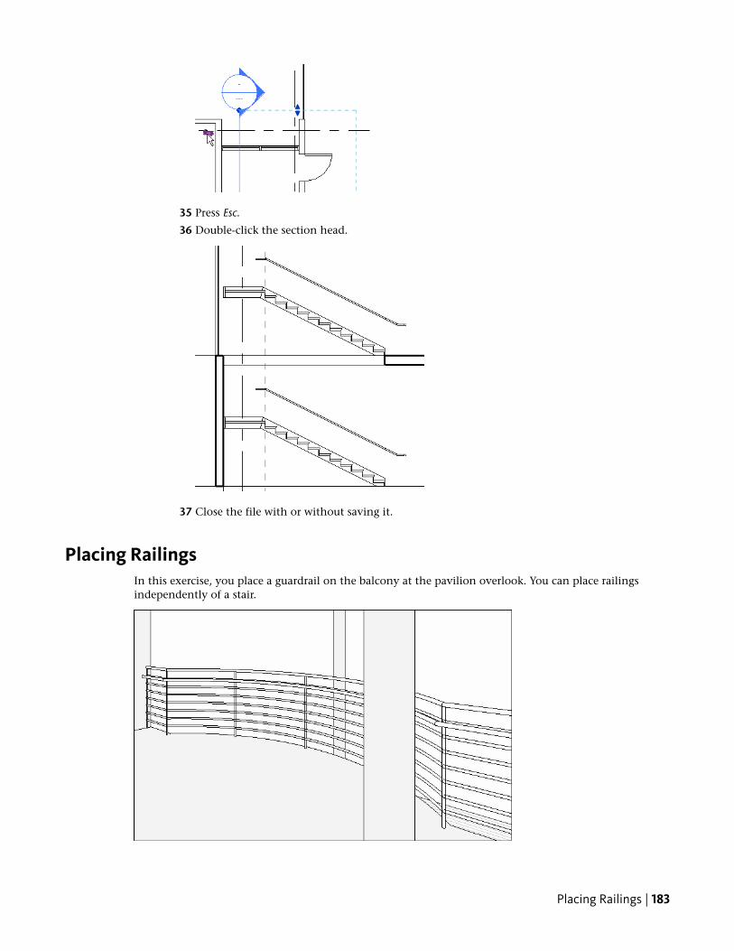
35 Press Esc.
36 Double-click the section head.
37 Close the file with or without saving it.
Placing RailingsIn this exercise, you place a guardrail on the balcony at the pavilion overlook. You can place railingsindependently of a stair.
Placing Railings | 183

Training File
■ Click ➤ Open.
■ In the left pane of the Open dialog, click Training Files, and open Imperial\RAC_SR_04_Place_Railing_i.rvt.
Create a stair
1 In the Project Browser, under Floor Plans, double-click 02 - Floor, and zoom in to the balconynear the center of the building.
2 Click Home tab ➤ Circulation panel ➤ Railing.
3 Click Create Railing Path tab ➤ Element panel ➤ Railing Properties.
4 In the Instance Properties dialog, for Type, select Guardrail - Pipe, and click OK.
5 Click Create Railing Path tab ➤ Draw panel ➤ (Pick Lines).
6 On the Options Bar, for Offset, type 4''.
You use the floor slab edge as the basis for the geometry of the railing.
7 Click the 3 balcony floor edges so the offset is to the inside.
NOTE To avoid having to trim the drawing, make sure you select the floor edge for the vertical linesrather than the curtain wall.
184 | Chapter 10 Adding Stairs and Railings

8 Click Create Railing Path tab ➤ Railing panel ➤ Finish Railing.
9 Press Esc.
Create a 3D view
10 Click View tab ➤ Create panel ➤ 3D View drop-down ➤ Camera.
Place a camera to see the railing that has been placed in a 3D view.
11 Click to place the eye position, and click to place the view target, as shown.
Placing Railings | 185

12 Press Esc, and view the railing in the 3D view.
13 Close the file with or without saving it.
186 | Chapter 10 Adding Stairs and Railings

Adding Other DesignElements
In this lesson, you add objects and design elements to the basic building layout. You learn to:
■ Create room separation lines and place rooms.
■ Define a color scheme based on area and apply it to the view.
■ Create area plans and define a schedule to analyze building use.
■ Add a furniture layout to the plan view and schedule the components.
Color scheme and color fill legend applied to the view
Placing RoomsIn this exercise, you place rooms in the project. You add room separation lines to divide the public circulationarea into 3 separate areas to allow for 3 separate rooms.
11
187
Training File
■ Click ➤ Open.
■ In the left pane of the Open dialog, click Training Files, and openImperial\RAC_ODE_01_Place_Rooms_i.rvt.
Place rooms
1 In the Project Browser, under Floor Plans, double-click 01 - Entry Level.
2 Click Home tab ➤ Room & Area panel ➤ Room drop-down ➤ Room.
3 On the Options Bar, clear Tag on placement.
Tags can be added to rooms as they are placed into the model. However, for this tutorial, youadd room tags in a separate exercise.
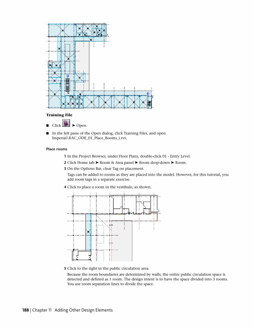
4 Click to place a room in the vestibule, as shown.
5 Click to the right in the public circulation area.
Because the room boundaries are determined by walls, the entire public circulation space isdetected and defined as 1 room. The design intent is to have the space divided into 3 rooms.You use room separation lines to divide the space.
188 | Chapter 11 Adding Other Design Elements
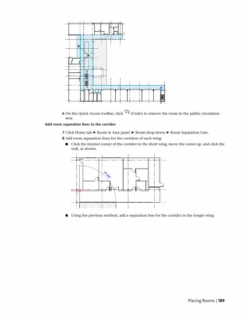
6 On the Quick Access toolbar, click (Undo) to remove the room in the public circulationarea.
Add room separation lines to the corridor
7 Click Home tab ➤ Room & Area panel ➤ Room drop-down ➤ Room Separation Line.
8 Add room separation lines for the corridors of each wing:
■ Click the interior corner of the corridor in the short wing, move the cursor up, and click thewall, as shown.
■ Using the previous method, add a separation line for the corridor in the longer wing.
Placing Rooms | 189
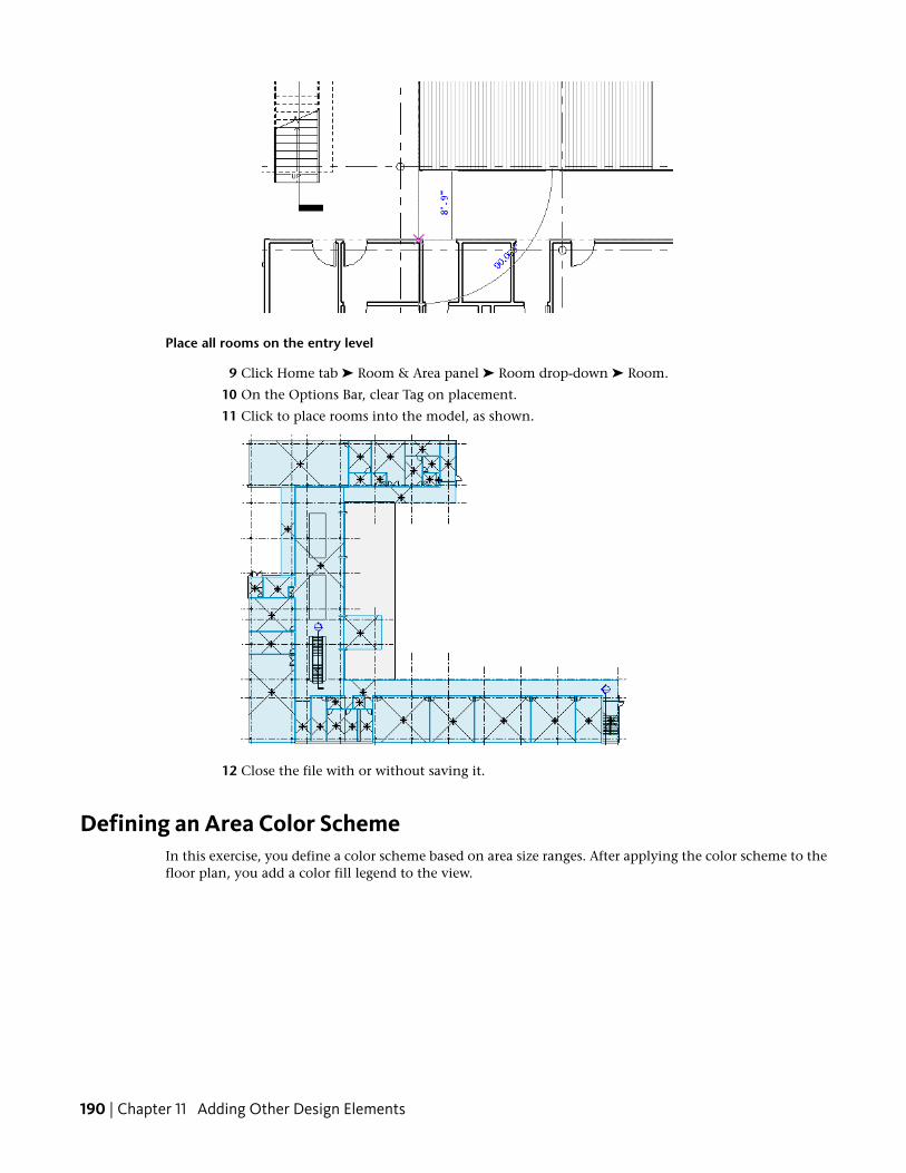
Place all rooms on the entry level
9 Click Home tab ➤ Room & Area panel ➤ Room drop-down ➤ Room.
10 On the Options Bar, clear Tag on placement.
11 Click to place rooms into the model, as shown.
12 Close the file with or without saving it.
Defining an Area Color SchemeIn this exercise, you define a color scheme based on area size ranges. After applying the color scheme to thefloor plan, you add a color fill legend to the view.
190 | Chapter 11 Adding Other Design Elements
Training File
■ Click ➤ Open.
■ In the left pane of the Open dialog, click Training Files, and openImperial\RAC_ODE_02_Color_Scheme_i.rvt.
Define a color scheme by area
1 In the Project Browser, under Floor Plans, double-click 01 - Entry Level.
2 In the Project Browser, under Floor Plans, right-click 01 - Entry Level, and click Properties.
3 In the Instance Properties dialog, for Color Scheme, click <none>.
4 In the Edit Color Scheme dialog, under Schemes, select Name.
You copy an existing color scheme and modify the scheme definition to use the Area parameter.
5 Click (Duplicate).
6 In the New color scheme dialog, type Area, and click OK.
7 Under Scheme Definition, for Color, select Area.
8 In the informational dialog, click OK.
9 To the right of the Color field, select By range.
When first created, the color scheme is set to By value. This creates a separate color for eachvalue, in this case Area. You want to create this color scheme by range rather than value.
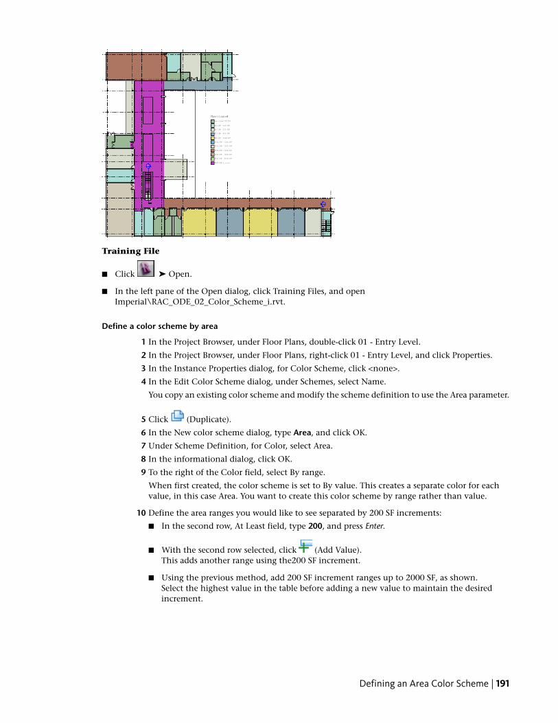
10 Define the area ranges you would like to see separated by 200 SF increments:
■ In the second row, At Least field, type 200, and press Enter.
■ With the second row selected, click (Add Value).This adds another range using the200 SF increment.
■ Using the previous method, add 200 SF increment ranges up to 2000 SF, as shown.Select the highest value in the table before adding a new value to maintain the desiredincrement.
Defining an Area Color Scheme | 191

11 Click OK twice.
The color scheme is applied to the view.
Add a color scheme legend
12 Click Home tab ➤ Room & Area panel ➤ Legend.
13 Click in the courtyard to place the legend.
192 | Chapter 11 Adding Other Design Elements
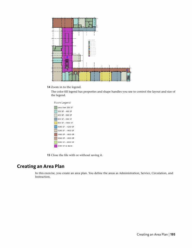
14 Zoom in to the legend.
The color fill legend has properties and shape handles you use to control the layout and size ofthe legend.
15 Close the file with or without saving it.
Creating an Area PlanIn this exercise, you create an area plan. You define the areas as Administration, Service, Circulation, andInstruction.
Creating an Area Plan | 193
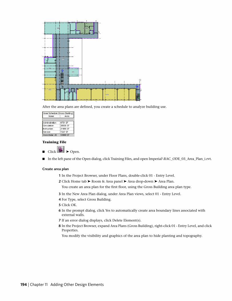
After the area plans are defined, you create a schedule to analyze building use.
Training File
■ Click ➤ Open.
■ In the left pane of the Open dialog, click Training Files, and open Imperial\RAC_ODE_03_Area_Plan_i.rvt.
Create area plan
1 In the Project Browser, under Floor Plans, double-click 01 - Entry Level.
2 Click Home tab ➤ Room & Area panel ➤ Area drop-down ➤ Area Plan.
You create an area plan for the first floor, using the Gross Building area plan type.
3 In the New Area Plan dialog, under Area Plan views, select 01 - Entry Level.
4 For Type, select Gross Building.
5 Click OK.
6 In the prompt dialog, click Yes to automatically create area boundary lines associated withexternal walls.
7 If an error dialog displays, click Delete Element(s).
8 In the Project Browser, expand Area Plans (Gross Building), right-click 01 - Entry Level, and clickProperties.
You modify the visibility and graphics of the area plan to hide planting and topography.
194 | Chapter 11 Adding Other Design Elements
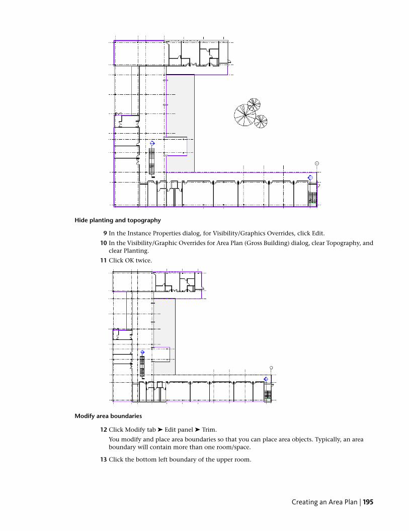
Hide planting and topography
9 In the Instance Properties dialog, for Visibility/Graphics Overrides, click Edit.
10 In the Visibility/Graphic Overrides for Area Plan (Gross Building) dialog, clear Topography, andclear Planting.
11 Click OK twice.
Modify area boundaries
12 Click Modify tab ➤ Edit panel ➤ Trim.
You modify and place area boundaries so that you can place area objects. Typically, an areaboundary will contain more than one room/space.
13 Click the bottom left boundary of the upper room.
Creating an Area Plan | 195
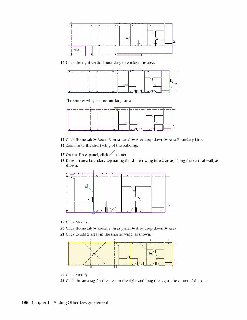
14 Click the right vertical boundary to enclose the area.
The shorter wing is now one large area.
15 Click Home tab ➤ Room & Area panel ➤ Area drop-down ➤ Area Boundary Line.
16 Zoom in to the short wing of the building.
17 On the Draw panel, click (Line).
18 Draw an area boundary separating the shorter wing into 2 areas, along the vertical wall, asshown.
19 Click Modify.
20 Click Home tab ➤ Room & Area panel ➤ Area drop-down ➤ Area.
21 Click to add 2 areas in the shorter wing, as shown.
22 Click Modify.
23 Click the area tag for the area on the right and drag the tag to the center of the area.
196 | Chapter 11 Adding Other Design Elements

Edit area tags
24 Click the tag, and click the text label to select the tag in the left area.
25 Type Service, and press Enter.
The names you apply to the areas will be used to create a color fill and area schedule for theproject.
26 Using the previous method, change the area tag in the right area to Administration.
Define a color fill
27 In the Project Browser, under Area Plans (Gross Building), right-click 01 - Entry Level, and clickProperties.
28 In the Instance Properties dialog, for Color Scheme, click <none>.
29 In the Edit Color Scheme dialog, under the Schemes section, select Gross Building Area, and inthe Scheme Definition section, for Color, select Name.
You define a color fill for the view where the area name is used as the parameter to assign thecolor.
30 In the informational dialog, click OK.
31 Click OK twice.
The area plan can be refined as required by the project. (For this exercise, a completed trainingfile has been provided where area plans are already defined.)
32 Close the file with or without saving it.
Open the completed training file
33 Open the completed training file:
■ Click ➤ Open.
■ In the left pane of the Open dialog, click Training Files, and openImperial\RAC_ODE_04_Area_Plans_Complete_i.rvt.
Creating an Area Plan | 197

34 Optionally, in the Project Browser, expand Area Plans (Gross Building), and open the preparedarea plans.
Create a schedule to analyze area plans
35 Click View tab ➤ Create panel ➤ Schedules drop-down ➤ Schedule/Quantities.
36 In the New Schedule dialog, for Category, select Areas (Gross Building), and click OK.
37 In the Schedule Properties dialog, for Available fields, select Name, and click Add.
38 Using the previous method, add Area.
39 Specify options on the Sorting/Grouping tab:
■ Select Grand totals.
■ Clear Itemize every instance.
■ For Sort by, select Name.
40 On the Formatting tab, under Fields, select Area.
41 Under Field formatting, select Calculate totals, and click OK.
42 Close the file with or without saving it.
Adding FurnitureIn this exercise, you add furniture components to the project. The process is similar for adding any othercomponents to a project.
You also create a schedule to track the components added to the project.
Training File
■ Click ➤ Open.
■ In the left pane of the Open dialog, click Training Files, and openImperial\RAC_ODE_05_Add_Furniture_i.rvt.
198 | Chapter 11 Adding Other Design Elements

Add tables and chairs
1 In the Project Browser, under Floor Plans, double-click 01 - Entry Level.
2 Zoom in to the left side of the shorter wing.
3 Click Insert tab ➤ Load from Library panel ➤ Load Family.
You add a dining table and chairs to the cafeteria area. Because this family is not currently loadedinto the project, you load it from an external library.
4 In the left pane of the Load Family dialog, click Training Files, and openImperial\Families\Table-Dining Round w Chairs.rfa.
5 Click Home tab ➤ Build panel ➤ Component drop-down ➤ Place a Component.
6 In the Type Selector, verify that Table-Dining Round w Chairs 36'' Diameter is selected.
7 Click to place an instance of the table and chairs in the upper-left corner of the cafeteria.
8 Place 2 additional tables/chairs, as shown.
9 Click Modify.
Array the tables and chairs
10 While pressing Ctrl, select the 3 table/chairs components.
11 On the Modify panel, click Array.
You use the Array command to quickly fill the room with the table layout.
12 Press Tab to highlight, and click to select the midpoint of the top table, move the cursor to theright, and click to specify the array direction. (The exact distance is not important.)
Adding Furniture | 199

13 Select the array number, and type 7.
Press Enter.
Delete extra furniture
14 While pressing Ctrl, select the columns of tables 4-7, and on the Group panel, click Ungroup.
Ungroup the elements of the array to erase the unnecessary tables and chairs from the layout.
15 Press Esc.
16 While pressing Ctrl, select the bottom table in columns 4-6, and the entire column 7 of tables,as shown.
200 | Chapter 11 Adding Other Design Elements
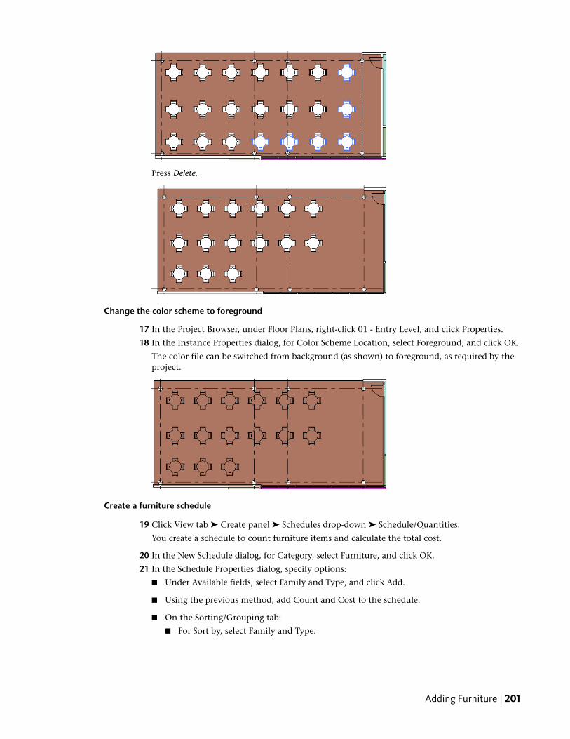
Press Delete.
Change the color scheme to foreground
17 In the Project Browser, under Floor Plans, right-click 01 - Entry Level, and click Properties.
18 In the Instance Properties dialog, for Color Scheme Location, select Foreground, and click OK.
The color file can be switched from background (as shown) to foreground, as required by theproject.
Create a furniture schedule
19 Click View tab ➤ Create panel ➤ Schedules drop-down ➤ Schedule/Quantities.
You create a schedule to count furniture items and calculate the total cost.
20 In the New Schedule dialog, for Category, select Furniture, and click OK.
21 In the Schedule Properties dialog, specify options:
■ Under Available fields, select Family and Type, and click Add.
■ Using the previous method, add Count and Cost to the schedule.
■ On the Sorting/Grouping tab:
■ For Sort by, select Family and Type.
Adding Furniture | 201

■ Select Grand totals.
■ Clear Itemize every instance.
■ On the Formatting tab:
■ Under Fields, select Cost.
■ Under Field formatting, select Calculate totals.
The cost of the items is calculated as a running total.
■ Click OK.
22 Double-click the heading column dividers to expand the columns to fit the entries.
No cost information is being reported because values have not been specified for this parameterin the family. You add a cost value for the component in the family parameters so the total costcan be calculated.
Add cost values to the furniture families
23 In the Project Browser, Expand Families/Furniture/Chair-Breuer, and double-click Chair-Breuer.
24 In the Type Properties dialog, for Cost, type 45, and click OK.
25 Using the previous method, for the Table-Dining Round w Chairs/36'' Diameter family, specifya cost of 300.
The schedule updates with the cost values.
26 Close the file with or without saving it.
202 | Chapter 11 Adding Other Design Elements