
Revision October REGULATORY GUIDE - NRC
14
Revision 1 October 1983 U.S. NUCLEAR REGULATORY COMMISSION REGULATORY GUIDE OFFICE OF NUCLEAR REGULATORY RESEARCH REGULATORY GUIDE 5.38 (Task SG 0484) NONDESTRUCTIVE ASSAY OF HIGH-ENRICHMENT URANIUM FUEL PLATES BY GAMMA RAY SPECTROMETRY A. INTRODUCTION Part 70 of Title 10 of the Code of Federal Regulations requires each licensee authorized to possess more than 350 grams of contained 235U to conduct a physicalinven tory of all special nuclear material in its possession at intervals not to exceed 12 months. Each licensee authorized to possess more than one effective kilogram of high enrichment uranium is required to conduct measured physical inventories of special nuclear materials at bimonthly intervals. Further, these licensees are required to conduct their nuclear material physical inventories in compliance with specific requirements set forth in Part 70. Inventory procedures acceptable to the NRC staff for complying with these provisions of Part 70 are detailed in Regulatory Guide 5.13, "Conduct of Nuclear Material Physical Inven tories." The fuel for certain nuclear reactors consists of highly enriched uranium fabricated into flat or bowed plates. Typically, these plates are relatively thin so that a signifi cant percentage of the 235U gamma rays penetrates the fuel and cladding. When the measurement conditions are properly controlled and corrections are made for variations in the attenuation of the gamma rays, a measurement of the 235 U gamma rays can be used as an acceptable measurement of the distribution and the total 23 5 U content of each fuel plate. In lieu of assaying the product fuel plates, fuel plate core compacts may be assayed through the procedures detailed in this guide provided steps are taken to ensure the traceability and integrity of encapsulation of each assayed fuel plate core compact. This guide describes features of a gamma ray spectrometry system acceptable to the NRC staff for nondestructive assay of high-enrichment uranium fuel plates or fuel plate core compacts. Any guidance in this document related to information collection activities has been cleared under OMB Clearance No. 3150-0009. USNRC REGULATORY GUIDES Regulatory Guides are issued to describe and make available to the public methods acceptable to the NRC staff of implementing specific parts of the Commission's regulations, to delineate tech niques used by the staff in evaluating specific problems or postu lated accidents or to provide guidance to applicants. Regulatory Guides are no? substitutes for regulations, and compliance with .___/ them is not required. Methods and solutions different from those set out in the guides will be acceptable if they provide a basis for the findings requisite to the issuance or continuance of a permit or license by the Commission. This guide was issued after consideration of comments received from the public. Comments and suggestions for improvements in these guides are encouraged at all times, and guides will be revised, as appropriate, to accommodate comments and to reflect new informa tion or experience. B. DISCUSSION The number, energy, and intensity of gamma rays associated with the decay of 235 U provide the basis for nondestructive assay of high-enrichment fuel plates by gamma ray spectrometry (Ref. 1). The 185.7-keV gamma ray is the most useful 235 U gamma ray for this application; it is emitted at the rate of 4.25 x 10 4 gamma rays per second per gram of 235 U. Lower energy gamma rays emitted by 235 U are less penetrating and more sensitive to errors due to fluctuations in cladding and core thickness. In general, more accurate fuel plate assays may be made by measuring only the activity attributable to the 185.7-keV 235 U gamma ray. Assay measurements are made by integrating the response observed during the scanning of single fuel plates and comparing each response to a calibration based on the response to known calibration standards. 1. GAMMA RAY MEASUREMENT SYSTEM 1.1 Gamma Ray Detection System 1.1.1 Gamma Ray Detector High-resolution gamma ray detectors, i.e., high-purity germanium, HPGe, also referred to as intrinsic germanium (IG), or lithium-drifted germanium [Ge(Li)] detectors, provide resolution beyond that required for this assay application. While the performance of high-resolution detectors is more than adequate, their low intrinsic detec tion efficiency, higher maintenance requirements, and high cost make them unattractive for the measurements dis cussed here. Most sodium iodide [NaI(TI)] scintillation detectors are capable of sufficient energy resolution to be used for the measurement of the 185.7-keV gamma rays. For plate Comments should be sent to the Secretary of the Commission, U.S. Nuclear Regulatory Commission, Washington, D.C. 20555, Attention: Docketing and Service Branch. The guides are issued in the following ten broad divisions: 1. Power Reactors 6. Products 2. Research and Test Reactors 7. Transportation 3. Fuels and Materials Facilities 8. Occupational Health 4. Environmental and Siting 9. Antitrust and Financial Review 5. Materials and Plant Protection 10. General Copies of issued guides may be purchased at the current Government Printing Office price. A subscription service for future guides in spe cific divisions is available through the Government Printing Office. Information on the subscription service and current GPO prices may be obtained by writing the U.S. Nuclear Regulatory Commission, Washington, D.C. 20555, Attention: Publications Sales Manager.
Transcript of Revision October REGULATORY GUIDE - NRC
Revision 1 October 1983U.S. NUCLEAR REGULATORY COMMISSION
REGULATORY GUIDE OFFICE OF NUCLEAR REGULATORY RESEARCH
REGULATORY GUIDE 5.38 (Task SG 0484)
NONDESTRUCTIVE ASSAY OF HIGH-ENRICHMENT URANIUM FUEL PLATES BY GAMMA RAY SPECTROMETRY
A. INTRODUCTION
Part 70 of Title 10 of the Code of Federal Regulations requires each licensee authorized to possess more than 350 grams of contained 235U to conduct a physicalinventory of all special nuclear material in its possession at intervals not to exceed 12 months. Each licensee authorized to possess more than one effective kilogram of highenrichment uranium is required to conduct measured physical inventories of special nuclear materials at bimonthly intervals. Further, these licensees are required to conduct their nuclear material physical inventories in compliance with specific requirements set forth in Part 70. Inventory procedures acceptable to the NRC staff for complying with these provisions of Part 70 are detailed in Regulatory Guide 5.13, "Conduct of Nuclear Material Physical Inventories."
The fuel for certain nuclear reactors consists of highly enriched uranium fabricated into flat or bowed plates. Typically, these plates are relatively thin so that a significant percentage of the 235U gamma rays penetrates the fuel and cladding. When the measurement conditions are properly controlled and corrections are made for variations in the attenuation of the gamma rays, a measurement of the 2 3 5 U gamma rays can be used as an acceptable measurement of the distribution and the total 2 3 5
U content of each fuel plate. In lieu of assaying the product fuel plates, fuel plate core compacts may be assayed through the procedures detailed in this guide provided steps are taken to ensure the traceability and integrity of encapsulation of each assayed fuel plate core compact. This guide describes features of a gamma ray spectrometry system acceptable to the NRC staff for nondestructive assay of high-enrichment uranium fuel plates or fuel plate core compacts.
Any guidance in this document related to information collection activities has been cleared under OMB Clearance No. 3150-0009.
USNRC REGULATORY GUIDES
Regulatory Guides are issued to describe and make available to the public methods acceptable to the NRC staff of implementing specific parts of the Commission's regulations, to delineate techniques used by the staff in evaluating specific problems or postulated accidents or to provide guidance to applicants. Regulatory Guides are no? substitutes for regulations, and compliance with
.___/ them is not required. Methods and solutions different from those set out in the guides will be acceptable if they provide a basis for the findings requisite to the issuance or continuance of a permit or license by the Commission.
This guide was issued after consideration of comments received from the public. Comments and suggestions for improvements in these guides are encouraged at all times, and guides will be revised, as appropriate, to accommodate comments and to reflect new information or experience.
B. DISCUSSION
The number, energy, and intensity of gamma rays associated with the decay of 2 3 5 U provide the basis for nondestructive assay of high-enrichment fuel plates by gamma ray spectrometry (Ref. 1). The 185.7-keV gamma ray is the most useful 2 3 5 U gamma ray for this application; it is emitted at the rate of 4.25 x 10⁴ gamma rays per second per gram of 2 3 5 U. Lower energy gamma rays emitted by 235 U are less penetrating and more sensitive to errors due to fluctuations in cladding and core thickness. In general, more accurate fuel plate assays may be made by measuring only the activity attributable to the 185.7-keV 235 U gamma ray.
Assay measurements are made by integrating the response observed during the scanning of single fuel plates and comparing each response to a calibration based on the response to known calibration standards.
1. GAMMA RAY MEASUREMENT SYSTEM
1.1 Gamma Ray Detection System
1.1.1 Gamma Ray Detector
High-resolution gamma ray detectors, i.e., high-purity germanium, HPGe, also referred to as intrinsic germanium (IG), or lithium-drifted germanium [Ge(Li)] detectors, provide resolution beyond that required for this assay application. While the performance of high-resolution detectors is more than adequate, their low intrinsic detection efficiency, higher maintenance requirements, and high cost make them unattractive for the measurements discussed here.
Most sodium iodide [NaI(TI)] scintillation detectors are capable of sufficient energy resolution to be used for the measurement of the 185.7-keV gamma rays. For plate
Comments should be sent to the Secretary of the Commission, U.S. Nuclear Regulatory Commission, Washington, D.C. 20555, Attention: Docketing and Service Branch.
The guides are issued in the following ten broad divisions:
1. Power Reactors 6. Products 2. Research and Test Reactors 7. Transportation 3. Fuels and Materials Facilities 8. Occupational Health 4. Environmental and Siting 9. Antitrust and Financial Review 5. Materials and Plant Protection 10. General
Copies of issued guides may be purchased at the current Government Printing Office price. A subscription service for future guides in specific divisions is available through the Government Printing Office. Information on the subscription service and current GPO prices may be obtained by writing the U.S. Nuclear Regulatory Commission, Washington, D.C. 20555, Attention: Publications Sales Manager.
assays by scanning techniques, the detector diameter is determined by the fuel plate width and the scanning method selected (see Section B.l.2 of this guide). For passive counting of the total fuel plate (see Section B. 1.3 of this guide), the detector diameter is not a critical parameter, and detectors suitable for plate scanning would also be adequate for the passive counting measurements. In both cases, the thickness of the Nal crystal is selected to provide a high probability of detecting the 185.7-keV gamma rays and a low probability of detecting higher energy radiation. A crystal thickness of 1/2 to 1 inch (13 to 25 mm) is recommended.
For measurements to be reproducible, it is recommended that the detection system be energy stabilized. Internally "seeded" NaI crystals that contain a radioactive source (typically 24'Am) to produce a reference energy pulse are commercially available. The detection system is stabilized on the reference, and the amplifier gain is automatically corrected to ensure that the reference energy and the rest of the spectrum remain fixed.
1.1.2 Gamma Ray Collimator
The detector collimator is intended to shield the detector from radiation from all sources except those that are to be measured. Thus the collimator shielding not only defines the front area of the detector crystal to be exposed but it also shields the sides and, if possible, the rear of the detector. The front opening of the collimator is designed to define the field of view appropriate for the measurement technique to be employed. Once a measurement system is calibrated with a particular collimator configuration, that configuration must be maintained for all subsequent assays. Any change in the collimation system will necessitate recalibration of the measurement system.
1.1.2.1 Collimation for Scanning Techniques. To ensure that the only gamma ray activity detected originates from a well-defined segment of the fuel plate, the detector is shielded from extraneous background radiations and collimated to define the plate area "seen" by the detector crystal. The collimator consists of a disk of appropriate shielding material. A slit is machined through the center of the disk to allow only those gamma rays emitted within the slit opening to strike the detector. The disk thickness is a minimum of six mean free path lengths to effectively stop all 185.7-keV gamma rays emitted from outside the field of view. For more compact counting geometries, higher density shielding materials (such as tungsten or lead) can be used. The linear dimensions of other shielding materials scale down according to the decrease in mean free path length. 1
The probability of detection for gamma rays emitted at the center of the collimator slit is greater than that for gamma rays emitted near the ends of the slit. This effect becomes increasingly important at small detector-toplate spacing, especially when scanning near the edge of a
1 For the 185.7-keV gamma ray from 235U, a thickness equivalent to six mean free path lengths in lead is approximately 0.45 cm; in tungsten it is approximately 0.33 cm; and in iron it is approximately 4.9 cm.
plate. To minimize this detection nonuniformity and to minimize the sensitivity to vibration, the detector-to-plate distance can be made large, especially with respect to the dimensions of the slit opening. As an alternative means of reducing the detection nonuniformity across the slit, the slit opening can be divided into channels by inserting a honeycomb baffle into the slit or by fabricating the collimator by drilling holes through the disk in a pattern that ensures that each hole is surrounded by a minimum wall thickness of 0.2 mean free path length. A 7.0-cm-thick iron disk with holes less than 0.5 cm in diameter drilled in a pattern having 0.2 cm of wall between adjacent holes is one example of a collimator that would perform satisfactorily. A large number of small-diameter holes is preferable to a few large-diameter holes.
1.1.2.2 Collimation for Total Plate Counting. For total plate counting (see Section B. 1.3), the collimator opening is circular with a diameter less than that of the NaI crystal. Furthermore, the collimator diameter and detector-to-plate distance are chosen so that the field of view includes the entire fuel plate. (Note that in this more relaxed counting geometry, the viewing area may have to be isolated from nearby sources of the 185.7-keV gamma rays in the line of sight of the detector. This can be accomplished by shadow shielding with small pieces of lead or tungsten.)
1.1.3 Multiple Detectors
Several detectors may be used to shorten the measurement time. The detectors can be positioned to measure different segments of a single fuel plate or several separate fuel plates simultaneously. In some cases it may be useful to sum the response from two detectors positioned on opposite sides of a plate to increase counting efficiency. In such cases, it is essential that the relative response of such detectors be known and checked at frequent intervals for continued stability.
1.2 Scanning Techniques
It is critical that the scanning apparatus for moving the plates relative to the detector provide a uniform and reproducible scan. The importance of a well-constructed mechanically stable conveyor cannot be overemphasized. Either the detector can be moved and the plate held stationary, or the plate can be moved past a fixed detector. If the detector collimator field of view extends beyond the edges of the fuel plate, care must be exercised to maintain the detector-to-plate spacing within close tolerances to minimize errors caused by the resulting dependence of count rate on this spacing. This is especially important in the case of close spacing, which is sometimes desirable to maximize the count rate. However, a superior collimator configuration from this point of view would be one in which the field of view is filled with active material over a range of detector-toplate distances. In this case, the measured material acts as an area source for which the counting rate is nearly independent of the detector-to-plate spacing. Therefore, in the "sweeping spot scan" technique discussed in Section B. 1.2.2, the spacing is not as critical a measurement parameter. Various commercial conveying systems have been used and
5.38-2
K-
¾�

found to be adequate. Such systems may significantly reduce the cost of designing and building new scanning mechanisms. High-precision tool equipment such as milling
•, machines, lathes, and x-y scanning tables can be investigated. Numerically controlled units offer additional advantages when they can be incorporated into a scanning system. This is particularly true when an automated scanning system is being developed.
Fuel plate core compacts may be sufficiently small to permit total assay in a fixed-geometry counting system without scanning (see Section B.1.3). The scanning techniques for fuel plates discussed in the following subsections can also be used for core compacts when total fixed compact counting is not possible.
1.2.1 Linear Total Scan
The detector collimation consists of a rectangular opening that extends across the width of the fuel plates beyond the edges of the uranium core contained within the plate cladding. Scanning the total plate is accomplished by starting the count sequence on the end of a plate and continuing to count until the entire length of plate has been scanned.
To ensure that gamma rays emitted anywhere across the face of the fuel plate have an equal probability of being detected, it is necessary that the diameter of the detector crystal exceed the plate width or that the detector be
.•- positioned away from the plate.
Use of the spot or circular collimator scan technique eliminates or reduces to insignificance most of these edge effects.
1.2.2 Sweeping Spot Scan
If the collimator channel width is smaller than the fuel plate width, the viewing area (spot) can be swept across the plate as the detector scans along the length of the plate (Ref. 2). This scanning technique can be readily adapted to scanning bowed plates through the use of a cam that is designed to maintain the detectoi-to-plate distance constant over the entire fuel plate. The collimator channel dimensions can be selected to provide compatible information on the uniformity of the fuel plate, which is frequently obtained by comparing fixed (static) spot counts at a variety of locations to reference counts.
1.2.3 Sampled Increment Assay
When used in conjunction with radiographic dimensional measurements performed on all fuel plates, the 235 U content of a fuel plate can be measured by scanning the ends of each fuel plate and sampling the balance of the plate. It is necessary to measure the dimensions of the fuel core loading radiographically through gamma ray scanning
___ along the length of the plate or by spot-scanning the fuel plate ends and measuring the distance between end spots where the fuel loading stops. The 235 U content of the plate
is then determined by averaging the results of sample spot measurements of the 2 3 5 U content per unit area at a number of sites along the plate and multiplying this average value by the measured area of the fuel core. The radiograph of each plate is examined to ensure that the core filler is uniform since nonuniformities would invalidate this type of assay.
The collimator shape and dimensions can be selected to provide compatible information on the uniformity of the fuel plate.
1.3 Passive Total Counting Techniques
A single passive gamma count of a fuel plate can be used to obtain the information of primary concern, namely the total 23SU content of the plate. The detector response in a "wide-angle" counting geometry can be converted to grams of 2 3 5 U in the plate if the response with standard fuel plates is known for the same counting geometry and if appropriate attenuation corrections are made with suitable transmission sources.
The detector collimator and detector-to-plate distance defines a field of view that (a) includes the entire fuel plate and (b) is isolated from other sources of radiation in the line of sight of the detector. Provide a measurement platform to facilitate the reproducible placement of the fuel plates, transmission sources, detector, and collimator shielding in a standard measurement configuration.
Core compacts are also to be assayed in this way provided representative standards are used to calibrate the measurement for the geometry pertaining to these items.
Additional details on passive total sample counting and the associated attenuation corrections for assay of special nuclear materials are given in References 3 and 4.
1.4 Computer Control
Computer control of the plate scanning techniques can greatly reduce the associated manpower requirements and improve measurement reproducibility. The computer can be used to control data acquisition by accumulating counts according to a predetermined scheme. Also, the computer can be used for data analysis, including background and attenuation corrections and intermachine normalization, calibration, error analysis, and diagnostic test measurements and analyses. Report preparation and data recording for subsequent analysis are also readily accomplished through an appropriately designed computer-controlled system. Use of a computer can be of great value in many of these functions for the total passive gamma counting technique as well.
2. INTERPRETATION OF MEASUREMENT DATA
The raw measurement data from either a scanning or a total passive counting technique can be distorted by several effects for which corrections should be made for accurate assays. The three factors discussed below are the most
5.38-3

important potential sources of measurement error that can give rise to significant misinterpretation of the data.
2.1 Enrichment Variations
Licensees authorized to possess highly enriched uranium are required to account for each element and isotope as prescribed in § 70.51. Under the conditions detailed in this guide, the 2 3 5 U content of individual plates is measured. To determine the total uranium content of each plate, the 235U enrichment of the core filler must be known from separate measurements.
Enrichment variations may also alter the radiation background in the gamma ray energy region of interest and cause fluctuations in the 2 3 5 U assay. The 2 3 8 U decays by alpha particle emission to 2 3 4 Th. The 2 3 4 Th then decays by beta particle emission with a half-life of 24.1 days to 2 34 Pa which, in turn, decays by beta particle emission to 234U. Approximately 1 percent of the 234Pa decays are followed by high-energy (e.g., 1001 keV, 766 keV) gamma rays. These gamma rays frequently lose energy through Compton scattering and may appear in the 185-keV spectral region. It is important to note that activity from 234Pa may be altered by disturbing the equilibrium between 2 3 5 U and 2 3 4 Th, as frequently occurs in uranium chemical conversion processes. The interference due to variations in 2 3 8 U daughter activity becomes less important as the enrichment of 2 3 5 U increases. At enrichment levels above 90 percent, this problem can essentially be ignored.
2.2 Radiation Attenuation
Attenuation of gamma radiation mayrange from complete absorption of the radiation by the intervening material to partial energy loss of the emitted radiation through scattering processes. Both effects reduce the number of full-energy gamma ray events that are detected. Gamma rays from 235 U are attenuated in the uranium, in the cladding, and in the inert material that may be added with the uranium to form the core of the fuel plate. Through well-controlled product tolerance limits, each of these potential sources of signal variability can be controlled to permit accurate accountability assays.
2.2.1 Self-Attenuation
The photon attenuation coefficient of uranium for gamma ray energies corresponding to 2 3 5 U emissions is quite large (Ref. 5). Small changes in uranium density resulting from increased fuel loading or from variations in the manufacturing process can therefore significantly change the number of gamma rays that escape from the fuel plate.
2.2.2 Cladding Attenuation
Small variations in cladding thickness may cause significant variations in attenuation. These variations in attenuation can be measured by a simple gamma ray absorption test using thin sheets of cladding material as absorbers and vary-
ing the clad thickness over the range of thicknesses to be encountered in normal product variability.
2.2.3 Core Filler Attenuation
Radiation intensity measurements may be made of plates fabricated with different ratios of uranium to filler to show the effects of this type of attenuation. If significant effects are noted, plates can be categorized by core composition characteristics and the assay system can be independently calibrated for each category of fuel plates.
2.2.4 Attenuation Corrections
When the thickness of the core and cladding and the composition of the core material are known, an attenuation correction can be calculated and applied to improve the accuracy of the assay. These corrections must also be applied to the assays of the standards in the calibration procedure. Ultrasonic gauging may provide such a measure if the metallographic zones within the plate are sufficiently defined to provide a detectable interface.
The alternative attenuation correction can be based on a micrometer measurement of the total thickness of each plate. The clad thickness of a plate is estimated by subtracting the mean core thickness of the product plates, which is determined by periodically sampling product plates and cutting a cross section to permit visual measurement of clad and core thickness.
As long as the gamma ray attenuation corrections are computed on the basis of declared component thicknesses and composition (or on the basis of occasional measurements of these quantities), unnoticed plate-to-plate fluctuations in these parameters will undermine the accuracy of the assays. A far more reliable approach to the application of attenuation corrections is to measure the gamma ray transmission property of each plate (standard as well as unknown) as it is being assayed. This approach increases the complexity of the assay procedures, but poses the further advantages of ýl)rendering the calibration dependent only upon the 35U loading of the standard plates and independent of other plate properties and (2) making the sample plate assays insensitive to possible fluctuations in cladding thicknesses and core composition and thickness. General discussions of gamma ray attenuation corrections accompanying passive assays are given in References 3, 4, and 6. Specific details of a correction procedure for Materials Testing Reactor (MTR) fuel plates are given in the appendix to this guide.
2.3 Interfering Radiations
As noted in Section B.2.1 of this guide, an internal background variation may arise from changes in the amount of 2 3 8 U present in a fuel plate or from changes in the ratio of 234Th to 238U resulting from fuel manufacturing processes. Fluctuations in the internal background cause the response of the unknown items to be different from the calibration standards, thereby creating a fluctuating measure-
5.38-4
ment bias. In addition, some discrete gamma ray interferences may be present at energies near 185.7 keV. For further information on these possible interferences, see Reference 7. Both the background and discrete gamma ray interferences are generally of minor importance, but they can be corrected for by measurement of additional regions of the gamma ray spectrum. Pertinent nuclear data for such measurements are available in Reference 1.
Other interfering radiations may come from external sources, from fuel plates awaiting assay, or from nearby radiation sources used for other measurements. This is not expected to be a major problem and can be controlled through (1) removing radiation sources, (2) shielding the detectors, and (3) monitoring the background at frequent intervals.
3. CALIBRATION AND VERIFICATION
3.1 Initial Operations
Calibration and the verification of assay predictions is an ongoing effort where performance is periodically monitored and the calibration relationship is modified to improve the accuracy of assay predictions. During initial operations, two means of basing preliminary calibrations are appropriate.
3.1.1 Foil Calibration Technique
Methods for calibrating scanning systems for highenrichment uranium fuel plates through the assay of prepared clad uranium foils are described in Reference 2. These methods may be used in place of or in addition to the technique described in the following subsection.
3.1.2 Fabricated Calibration Plates
Calibration standard fuel plates can be fabricated using special precautions to ensure that the amounts of uranium, 2 35 U, inert matrix, and cladding are accurately measured and that these parameters fall within manufacturing tolerances for product plates.
3.2 Routine Operations
The performance of the assay system is periodically monitored to ensure that the response of the assay system has not shifted since its last calibration. Control limits for acceptable performance can be established for the response to an appropriate working standard. The control chart of the responses to the working standard can be checked for indications of short-term instrument drift or malfunction. The control chart can also be analyzed to detect longterm shifts -within the measurement-to-measurement control limits that may be corrected by recalibrating the system. In general, however, it is important that observed instrument drifts and performance changes be investigated and remedied rather than compensated for by recalibration.
To ensure that the calibration remains valid during "-' normal operations and that accuracy estimates are rigorously
justified, assay predictions are periodically compared with
more accurate measurements of the content of typical fuel plates (see Regulatory Postion 4 of this guide). Guidance on methods to relate this assay to the national measurement system and to reconcile verification measurements is addressed in Regulatory Guide 5.58, "Considerations for Establishing Traceability of Special Nuclear Material Accounting Measurements."
C. REGULATORY POSITION
The content and distribution of 23 5U in high-enrichment uranium plates can be measured through the gamma ray assay methods discussed in this guide. Combining this measurement with the results of an independent measurement of the 2 3 SU enrichment enables the total uranium content of the fuel plates to be determined. The factors presented below should be taken into consideration for this assay method to be acceptable to the NRC staff.
1. MEASUREMENT SYSTEM
1.1 Gamma Ray Measurement System
1.1.1 Gamma Ray Detector
Thallium-activated sodium iodide [NaI(TI)] scintillation detectors are recommended for this assay application. When more than one detector is to be incorporated into the measurement system, the performance characteristics of the detectors should be matched as closely as possible, and the relative response of the detectors should be checked periodically to verify continued stability of the system. The diameter of the crystal should be larger than the projected view onto the crystal face through the collimator channel. A crystal thickness of 1/2 to 1 in. (13 to 25 mm) is recommended. The crystal should contain an internal seed that is doped with a suitable alpha emitter (typically 2 4 1 Am) to produce a reference energy peak for spectral stabilization. The seed should produce approximately 1,000 counts per second at the reference energy.
1.1.2 Collimator and Detector Shielding
The collimator should be fabricated of appropriate gamma ray shielding material such as iron, lead, or tungsten. The shielding should completely surround the detector and photomultiplier assembly and should be sufficiently thick to completely shield the detector from extraneous radiation.
1.1.3 Electronic Apparatus
All electronic systems should be powered by filtered, highly regulated power supplies. The ambient temperature and humidity in the vicinity of the scanning system should be controlled so that permitted fluctuations do not significantly affect the assay measurements. All electronic circuitry in signal-processing components should feature temperature compensation. Residual sensitivity to fluctuations in the ambient environment should be tested and monitored periodically.
5.38-5
The capability for multichannel gamma ray pulse height analysis with cathode ray tube spectral display should be provided. Signal-processing electronics capable of stabilizing on the reference energy peak produced by the alpha-emitterdoped seed should be provided to stabilize the energy spectrum.
1.2 Measurement System
Plate scanning should be accomplished by one of the three techniques discussed in Section B.1.2 of this guide. With these techniques, a mechanically sound, highly reproducible, automated scanning system should be employed. When more than one scanning system is employed, the assay responses of each system should be normalized so that each instrument provides consistent results. Verification data to estimate the bias for each assay system should be obtained with the same standard plate.
If a passive total counting technique is used, a stable, carefully constructed measurement platform should be employed to ensure the achievement of a reproducible measurement geometry.
1.3 Computer Control
A dedicated minicomputer to control data acquisition, calibration, diagnostic testing, and report preparation should be employed for fuel plate assay operations.
2. MEASUREMENT INTERPRETATION
2.1 Enrichment Variations
Procedures should be developed to ensure that the enrichment of the plates being scanned is known through separate measurements. Fuel plates generally satisfy the gamma ray penetrability criteria for quantitative 2 3 SU assay; they do not satisfy the criteria for nondestructive enrichment measurement through gamma ray spectrometry. 2
Facilities processing more than one uranium enrichment should maintain strict isotopic control and characterize the enrichment through appropriate measurement methods.
2.2 Attenuation Corrections
If computed attenuation corrections are used, attenuation variations arising from plate-to-plate changes in core thickness, core composition, and clad thickness should be determined over the range of product tolerance specifications. When such variations cause the assay standard deviation to exceed the standard deviation realized without the variations by 33 percent or more, procedures should be implemented to measure and apply a correction to the assay of each plate. It should be noted that routine measurement of attenuation corrections for each plate is recommended since such a procedure will remove the necessity of
2 Criteria for gamma ray uranium enrichment measurements are given in Regulatory Guide 5.21, "Nondestructive Uranium-235 Enrichment Assay by Gamma Ray Spectrometry." A proposed revision to this guide has been issued for comment as Task SG 044-4.
monitoring the variations in plate cladding thicknesses and core composition and thickness. For further detail on such corrections, see References 4 and 6 as well as the appendix to this guide.
2.3 Radiation Interferences
A graphic record of an acceptable (reference) gamma ray spectrum display (i.e., free of interferences and exhibiting nominal background) should be prepared. When radioactive interference may be encountered, the assay spectrum should be compared at appropriate intervals to the reference spectrum for indications of interference. Background radiation should be measured periodically during each operating shift.
3. MEASUREMENT CALIBRATION AND CONTROL
During initial operations, the assay system should be calibrated either by the foil calibration method or with specially prepared sample fuel plates as described in Section B.3.1 of this guide. Instrument response to appropriate working standards should also be checked periodically to verify the continued stability of the assay system calibration.
4. SOURCES OF VARIATION AND BIAS
4.1 Random Assay Standard Deviation Estimation
A replicate assay program should be established to generate data for the evaluation of the random assay standard deviation during each material balance period. During each bimonthly interval, a minimum of fifteen plates should be selected for replicate assay. The second assay of each plate selected for replicate assay should be made at least four hours after the first assay. Replicate assay data should be collected and analyzed at the end of the material balance period. The single-measurement standard deviation of the replicate assay differences should be computed as described in Reference 8. Replicate measurements should be made under the same conditions as routine measurements, performed throughout the production run, and checked for consistency. If the probability distributions for the data are not different, pooling of results from previous inventory periods can improve the random assay standard deviation estimates.
4.2 Calibration Standard Deviation Estimation
The calibration standard deviation associated with the assay of all fuel plates assayed during each calibration period throughout the material balance period can be determined through one of the procedures presented below. These methods are discussed in detail in ANSI 15.20-1975, "Guide to Calibration of NDA Systems," 3 and in Regulatory Guide 5.53, "Qualification, Calibration, and Error Estimation Methods for Nondestructive Assay" (a proposed revision to this guide has been issued for comment as Task SG 049-4).
3 Available from the American National Standards Institute, 1430 Broadway, New York, New York 10018.
5.38-6
I--
To estimate the standard deviation arising from the calibration procedure, the calibration should be based on a least-squares fitting of the calibration data to an appropriate model, then part of the calibration standard deviation
•-•- can be derived using the residual mean square. The standard deviation for the calibration standards includes the standard deviation of the reference values for the calibration standards. See ANSI 15.20-1975.
To ensure the validity of the measurements, the stable performance of the instrument should be monitored and normalized through the response to appropriate working standards that are assayed at frequent intervals. The frequency for assaying working standards should be determined through testing but should -not be lower than one test during each two-hour assay interval for spot response stability and one full scan test during each operating shift. For total passive counting techniques, assay of working standards should take place during each four-hour assay interval during each operating shift. Indications of shifting instrument performance should be investigated and the cause should be remedied. The instrument should then be recalibrated to ensure the validity of subsequent measurements.
In order to ensure that the calibration standards continue to adequately represent the unknown fuel plates, key production parameters that affect the observed response should be monitored through separate tests. (If transmission corrections are being measured for each plate assayed, the monitoring of plate parameters is less critical for assay accuracy.) Data should be compiled and analyzed at the close of each material balance period. When a production
S parameter shifts from previously established values, the impact of the shift on the response of the assay instrument should be determined through an appropriate experiment or calculation (Ref. 9). A bias correction should be determined and applied to all items assayed from the point of the parameter change. The variance of the bias estimate should be combined with the variance due to the calibration procedure. When the bias exceeds 3 percent of the plate contents in a single material balance period, when a trend of .1.5 percent or more is observed in three consecutive material balance periods, or when the standard deviation in the estimated bias is sufficient to increase the standard error (i.e., twice the standard deviation) of the assay above 0.5 percent, new calibration standards should be obtained and the scanning measurement system should be recalibrated.
As a further check on the continued validity of the calibration standards, a program to introduce new calibration standards periodically should be implemented. A minimum of one new calibration standard fuel plate should be introduced during each six-month period.
4.3 Bias Estimation
When two sets of measurements are made on each of a series of items and the accuracy of one of the methods used is considerably better than the other, the corresponding estimates can be compared to establish an estimate of bias
-- between the measurement methods and to estimate the
random assay standard deviation associated with the less accurate measurement method. To determine precisely the bias in the nondestructive assay measurement, the fuel plates selected for comparative measurements should be randomly selected but should span tile range of 2 3 5
U contents encountered in normal production. The fuel plates could have been selected from those rejected from the process stream for failing to meet quality assurance requirements. Each plate should be repeatedly assayed to reduce the random assay relative standard deviation (coefficient of variation) to less than 10 percent. To determine its 2 35 U and total uranium content, the plate should be completely dissolved and the resulting solution should be analyzed by high-accuracy assay procedures such as chemical and mass-spectrometric analyses.
For one material balance period during the initial implementation of this guide, a product fuel plate should be randomly selected twice each week for an accuracy verification measurement. Following this initial implementation period, facilities manufacturing 100 or more fuel plates per week may reduce the verification frequency to one plate per week and pool the verification data (provided the two distributions can be tested to show no differences) for two consecutive material balance periods. Low-throughput facilities manufacturing less than 100 plates per week should verify at least 4 plates per material balance period through the procedures described above. At the close of each material balance period, data should generally be pooled (if allowable) to include the 15 most current data points. However, if the data are demonstrably stable over longer periods, using additional data points from previous compatible results is one method of reducing the random assay standard deviation estimate.
Two methods are presented for estimating the bias. When the 23SU content of the plates assayed using a common calibration relationship varies over a range of ±5 percent or more of all plate loadings, the bias should be estimated by Method No. 1. When plate loadings are tightly clustered about a nominal value, the bias should be estimated by Method No. 2.
Method No. 1. At the close of the reporting period, the assay value for each plate is plotted against the verified quantity. The verification data plot is examined for indications of nonlinearity or obvious outlier data. Anomalous indications should be investigated and remedied. Further details on handling outlier data are contained in Regulatory Guide 5.36, "Recommended Practice for Dealing with Outlying Observations." The comparison data should be analyzed as described in Regulatory Position 7.3 of Regulatory Guide 5.53, "Qualification, Calibration, and Error Estimation Methods for Nondestructive Assay." A proposed revision to this guide has been issued for comment as Task SG 049-4.
Method No. 2. When all plates contain essentially the same 235U content, the difference in the mean content values should be tested against zero as an indication of bias, and the standard deviation associated with an inventory of
5.38-7

plates should be estimated as the standard deviation of the mean difference. For individual plates, the standard deviation should be estimated as the standard deviation of a single measurement.
5. CORE COMPACT ASSAY
Final product assay in high-enrichment fuel plate manufacturing can also be accomplished through assaying each core compact following the procedures detailed in this guide and the following supplemental criteria:
1. Each core compact should carry a unique identification. Accountability records should be created for each
compact. The fuel plate should carry an identification corresponding to the compact identification.
2. Each fuel plate should be radiographically examined to ensure that the entire compact has been encapsulated.
3. Each fuel plate should be checked with a gamma ray probe to ensure qualitatively that the plate core is uranium of the normal product enrichment.
4. Calibration and error evaluation should follow the procedures for fuel plate assay.
5.38-8

APPENDIX
SAMPLE ATTENUATION CORRECTION BY TRANSMISSION MEASUREMENT FOR MATERIALS
TESTING REACTOR FUEL PLATES
1. BACKGROUND
Gamma ray assay data are subject to distortions due to the attenuation of the gamma ray flux by the intervening sample material and sample container. The data must be corrected for this effect or the amount of nuclear material being assayed will be underestimated. The measured intensity I for the 185.7-keV gamma radiation from a Materials Testing Reactor (MTR) fuel plate is related to the 23SU content MU of the fuel plate by:
MU = kI/C (1)
where k is a calibration constant that includes effects such as detector efficiency, counting geometry, and nuclear properties of uranium. The factor C is the correction factor that adjusts the raw data for the attenuation of the 18,5.7-keV gamma ray by the plate cladding and core material.
Determination of this attenuation correction factor can be accomplished using an external gamma ray source. (Ideally, this should be a 23 5U source. For details on how to use a transmission source with a gamma ray energy different from that measured in the assay, see Reference 4.) The radiation from this source is detected after it passes through the fuel plate, and that transmitted gamma intensity I I is compared with the source intensity with no plate present 10 to obtain the gamma ray transmission T through the plate materials:
T = 11/1 0 (2)
This total plate transmission can be subdivided as follows:
T=TT 2 (3) U c
where Tc is the gamma ray transmission through one thickness of the plate cladding, and TU is the transmission through the core material. (The same cladding thickness on both sides of the plate is assumed.)
The gamma ray transmission through a plate is dominated by the effect of the core material (i.e., TU < Tc), so it is convenient to treat the cladding transmission Tc as a constant. Furthermore, variations in the core composition will cause more drastic fluctuations in the gamma ray attenuation than the small variations in the cladding thickness tc. For example, a 20-mil (0.051 cm) aluminum cladding thickness attenuates the 185.7-keV gamma intensity according to:
Tc= e c ctc = 0.983 (4)
where lic is the mass absorption coefficient of the cladding at 185.7 keV (for aluminum, pc = 0.126 cm 2/g) and pc is the cladding density (for aluminum, pc = 2.7 g/cm 3 ). If the cladding thickness varies by as much as 10 percent, the corresponding variation in Tc will be only 0.2 percent. Thus an assumption of invariant cladding attenuation for a particular type of fuel plate will contribute very little to the assay variance when the constant cladding attenuation correction is applied. One then determines Tc for the fuel plates from careful measurement of the cladding thickness and application of Equation 4.
Under the above assumption, one can then determine the transmission of the core material TU from the measured total plate transmission T, knowledge of Tc, and Equation 3. The attenuation correction factor in Equation 1 is then given by (see References 3 and 4):
In TU
Tc (1- TU)(5)
2. IMPLEMENTATION
2.1 The Scanning Techniques
A small transmission source should be placed behind the fuel plate as shown in Figure 1. The transmission correction must be measured and applied at each scan point so that nonuniformities in core composition within a plate can be corrected for. The transmission of the plate T(i) is measured at each scan point i by determining (1) the plate count rate with the transmission source shielded I(i) (Figure 1A), (2) the total counting rate of the plate and unshielded transmission source IT(i) (Figure 1B), and (3) the transmission source count rate with no intervening plate 10 (i) (Figure 1C).
T(i) = [IT(i) - I(i)l /1o(i) (6)
If the transmission source is a small localized 2 35 U source, a plate assay with the attenuation correction will require two scans: one to get the I (i) values and one to get the I(i) values. (The quantity IoTi) will be constant at all scan points and can be measured at a separate time.) If the transmission source is another fuel plate that remains stationary with respect to the plate being assayed, the I0 (i) must be measured by scanning the transmission source fuel plate. That is, an unattenuated transmission source plate intensity 10 (i) must be measured at the same scan points i and associated with the corresponding IT(i) and 1(i) from the measurements with the unknown plate. The count arrays IT(i), I(i), and 10 (i) must be stored in the computer memory as they are measured. The counts I(i) are then corrected by the factor in Equation 5 for each total plate transmission T(i).
5.38-9
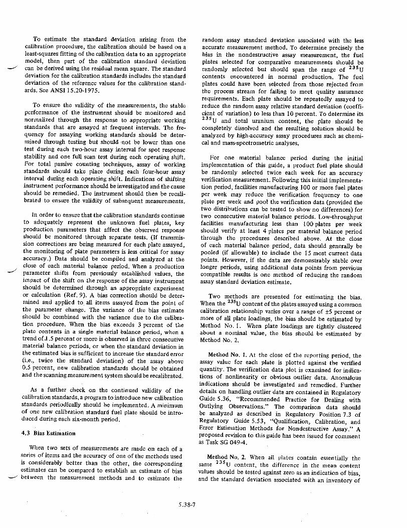
2.2 Total Passive Count Technique
In this case, an average attenuation correction is determined by measuring T for the entire plate using a 235U source behind the plate. An extended transmission source is recommended (ideally another fuel plate) in order to observe an average transmission over as much of the unknown plate as possible. The transmission source must not extend beyond or radiate around the edges of the fuel plate being assayed. In this case, the assay involves three counts: (1) fuel plate plus shielded transmission source I, (2) plate plus unshielded source IT, and (3) unshielded source with no plate Io. The average plate transmission T is then defined as:
T = (IT- I)/Io (7)
A single attenuation correction from Equation 5 is then applied to the passive count of the plate I.
3. MEASUREMENTS WITH HIGH-RESOLUTION SYSTEMS
The transmission of the 235U gamma ray can be inferred from measured transmission just above and just below 185.7 keV in energy. In one application using high-resolution gamma ray spectrometers (Reference 10), a 1 6 9Yb transmission source is used. Two of the gamma rays emitted by this isotope are at 177.2 and 198.0 keV, conveniently bracketing the 185.7-keV energy region. Measurement of T at these two energies and interpolating to 185.7 keV results in a determination of the attenuation correction factor C at the 235U gamma ray energy. A high-resolution detector system must be used in order to resolve the 177.2-, 185.7-, and 198.0-keV gamma ray peaks. In this way, the assay and transmission correction data are acquired simultaneously and multiple scans or multiple counts are not necessary. As a practical matter, 169yb has the short half-life of 32 days, so this source must be replaced frequently (or reirradiated in a reactor) in order to provide sufficient counts for a precise measurement of the attenuation corrections.
5.38-10

SORE TRANSMISSION SOURCE
COLLIMATED DETECTOR "'1?> oUNKNOWN FUEL
U(A)
*
(8)
*
(C)
Figure 1
A schematic of the measurement arrangements for MTR fuel plate gamma ray assay with measured attenuation correction. The close geometry of the scanning technique is used as an example. (A) Configuration for measuring 235 radiation coming only from the unknown fuel plate (I in the text). (B) Configuration for determining the sum of the fuel plate gamma intensity and the source intensity passing through the fuel plate (IT in the text). (C) Configuration for measuring
___ the incident transmission source gamma intensity (10 in the text).
5.38-11
PLATE
11.ýc
SOURCE
ý,ýc
REFERENCES
1. J. E. Cline, R. J. Gehrke, and L. D. McIssac, "Gamma Rays Emitted by the Fissionable Nuclides and Associated Isotopes," ANCR-1029, 1972.
2. N. S. Beyer, "Assay of 235U in Nuclear Reactor Fuel Elements by Gamma-Ray Scintillation Spectrometry," Proceedings of the 4th International Conference on Nondestructive Testing, London, 1963.
3. R. Sher and S. Untermeyer, The Detection of Fissionable Material by Nondestructive Means, American Nuclear Society Monograph, 1980.
4. R. H. Augustson and T. D. Reilly, "Fundamentals of Passive Nondestructive Assay of Fissionable Material," Los Alamos Scientific Laboratory, LA-5651-M, 1974.
5. E. Storm and H. Israel, "Photon Cross Sections from 0.001 to 100 MeV for Elements 1 Through 100," Los Alamos Scientific Laboratory, LA-3753, 1967.
6. J. L. Parker and T. D. Reilly, "Bulk Sample SelfAttenuation Correction by Transmission Measure-
ment," Proceedings of the ERDA X- and Gamma-Ray Symposium, Ann Arbor, Michigan, Conf. 760639, p. 219, May 1976.
7. T. D. Reilly, "Gamma-Ray Measurements for Uranium Enrichment Standards," Proceedings of the American Nuclear Society Topical Meeting on "Measurement Technology for Safeguards and Material Control," Kiawah Island, South Carolina, November 1979; National Bureau of Standards Special Publication No. 582, p. 103, June 1980.
8. J. L. Jaech, "Statistical Methods in Nuclear Materials Control," Atomic Energy Commission, Report No. TID-26298, 1973.
9. R. A. Forster, D. B. Smith, and H. 0. Menlove, "Error Analysis of a Cf-252 Fuel Rod Assay System," Los Alamos Scientific Laboratory, LA-5317, 1974.
10. E. R. Martin, D. F. Jones, and J. L. Parker, "GammaRay Measurements with the Segmented Gamma Scan," Los Alamos Scientific Laboratory, LA-7059-M, 1977.
5.38-12
VALUE/IMPACT STATEMENT
2. TECHNICAL APPROACH
Not applicable.
Regulatory Guide 5.38 was published in September 1974. The proposed action, a revision to this guide, is needed to bringthe guide upto date with respect to advances in measurement methods and changes in terminology.
1.2 Value Impact of Proposed Action
1.2.1 NRC Operations
The regulatory positions will be brought up to date.
1.2.2 Other Government Agencies
Not applicable.
1.2.3 Industry
Since industry is already applying the methods and procedures discussed in the guide, updating the guide should have no adverse impact.
1.2.4 Public
No adverse impact on the public can be foreseen.
1.3 Decision on Proposed Action
The regulatory guide should be revised to reflect the improvement in measurement techniques and to bring the language of the guide into conformity with current usage.
3. PROCEDURAL APPROACH
Of the procedural alternatives considered, revision of the existing regulatory guide was selected as the most advantageous and cost effective.
4. STATUTORY CONSIDERATIONS
4.1 NRC Authority
Authority for the proposed action is derived from the Atomic Energy Act of 1954, as amended, and the Energy Reorganization Act of 1974, as amended, and implemented through the Commission's regulations.
4.2 Need for NEPA Assessment
The proposed action is not a major action that may significantly affect the quality of the human environment and does not require an environmental impact statement.
5. RELATIONSHIP TO OTHER EXISTING OR PROPOSED REGULATIONS OR POLICIES
The proposed action is one of a series of revisions of existing regulatory guides on nondestructive assay techniques.
6. SUMMARY AND CONCLUSIONS
Regulatory Guide 5.38 should be revised to bring it up to date.
5.38-13
1. PROPOSED ACTION
1.1 Description and Need

UNITED STATES NUCLEAR REGULATORY COMMISSION
WASHINGTON, D.C. 20555
FIRST CLASS MAIL POSTAGE & FEES PAID
USNRC WASH 3 C
PERMIT No G-Lk
OFFICIAL BUSINESS PENALTY FOR PRIVATE USE. $300