November 1982 REGULATORY GUIDE - NRC: Home Page
15
U.S. NUCLEAR REGULATORY COMMISSION Revision 1 November 1982 REGULATORY GUIDE OFFICE OF NUCLEAR REGULATORY RESEARCH (Reissued February 1983 to correct page 1.145-7) REGULATORY GUIDE 1.145 ATMOSPHERIC DISPERSION MODELS FOR POTENTIAL ACCIDENT CONSEQUENCE ASSESSMENTS AT NUCLEAR POWER PLANTS A. INTRODUCTION Section 100.10 of 10 CFR Part 100, "Reactor Site Criteria," states that meteorological conditions at the site and surrounding area should be considered in determining the acceptability of a site for a power reactor. Section 50.34 of 10 CFR Part 50, "Domestic Licensing of Produc- tion and Utilization Facilities," requires that each applicant for a construction permit or operating license provide an analysis and evaluation of the design and performance of structures, systems, and components of the facility with the objective of assessing the risk to public health and safety resulting from the operation of the facility. Section 50.34 of 10 CFR Part 50 also states that special attention should be directed to the site evaluation factors identified in 10 CFR Part 100 in the assessment of the site. The regulatory positions presented in this guide repre- sent a substantial change from procedures previously used to determine relative concentrations for assessing the potential offsite radiological consequences for a range of postulated accidental releases of radioactive material to the atmosphere. These procedures now include consideration of plume meander, directional dependence of dispersion conditions, and wind frequencies for various locations around actual exclusion area and low population zone (LPZ) boundaries 3 The direction-dependent approach provides an improved basis for relating the Part 100-related review of a proposed reactor to specific site considerations. Accordingly, this guide provides an acceptable methodology for deter- mining site-specific relative concentrations (X/Q) and should be used in determining xJQ values for the evalua- tions discussed in Regulatory Guide 1.3, "Assumptions Used for Evaluating the Potential Radiological Conse- quences of a Loss of Coolant Accident for Boiling Water I For additional information concerning the bases for the regula- tory positions presented in this guide, see NUREG/CR-2260, "Technical Basis for Regulatory Guide 1.145." Reactors," and Regulatory Guide 1.4, "Assumptions Used for Evaluating the Potential Radiological Consequences of a Loss of Coolant Accident for Pressurized Water Reactors." A number of other regulatory guides also include recom- mendations for or references to radiological analyses of potential accidents. The applicability of the specific criteria discussed herein to these other analyses will be considered on a case-by-case basis. Until such time as generic guidelines are developed for such analyses, the methodology provided in this guide is acceptable to the NRC staff. The Advisory Committee on Reactor Safeguards has 1* been consulted concerning this guide and has concurred in the regulatory position. B. DISCUSSION The atmospheric diffusion 2 models described in this guide reflect review of recent experimental data on diffu- sion from releases at ground level at open sites and from releases at various locations on reactor facility buildings during stable atmospheric conditions with low windspeeds (Refs. I through 6). These tests confirm the existence of effluent plume "meander" during low windspeed condi- tions and neutral (D) and stable (E, F, and G) atmospheric stability conditions (as defined by the temperature differ- ence (AT) criteria in Regulatory Guide 1.23, "Onsite Meteorological Programs," and provide bases for quantify- ing the effects of plume meander on effluent concentra- tions. Effluent concentrations measured over a period of I hour under such conditions have been shown to be substantially lower than would be predicted using the traditional curves (Ref. 7) of lateral and vertical plume spread. Lines indicate substantive changes from previous issue. 2 1n discussions throughout this regulatory guide, atmospheric dispersion will be considered as consisting of two components: atmospheric transport due to organized or mean airflow within the atmosphere and amospheric diffusion due to disorganized or random air motions. Plume depletion and surface deposition of airborne materials are not included in the dispersion models descibed in this guide. USNRC REGULATORY GUIDES Regulatory Guides are issued to describe and make available to the public methods acceptable to the NRC staff of implementing specific parts of the Commission's regulations, to delineate tech- niques used by the staff in evaluating specific problems or postu- lated accidents or to provide guidance to applicants. Regulatory Guides are not substitutes for regulations, and compliance with them is not required. Methods and solutions different from those set out in the guides will be acceptable if they provide a basis for the findings requisite to the issuance or continuance of a permit or license by the Commission. This guide was issued after consideration of comments received from the public. Comments and suggestions for improvements in these guides are encouraged at all times, and guides will be revised, as appropriate, to accommodate comments and to reflect new informa- tion or experience. Comments should be sent to the Secretary of the Commission, U.S. Nuclear Regulatory Commission, Washington, D.C. 20555, Attention: Docketing and Service Branch. The guides are issued in the following ten broad divisions: 1. Power Reactors 6. Products 2. Research and Test Reactors 7. Transportation 3. Fuels and Materials Facilities 8. Occupational Health 4. Environmental and Siting 9. Antitrust and Financial Review 5. Materials and Plant Protection 10. General Copies of Issued guides may be purchased at the current Government Printing Office price. A subscription service for future guides in spe- cific divisions is available through the Government Printing Office. Information on the subscription service and current GPO prices may be obtained by writing the U.S. Nuclear Regulatory Commission, Washington, D.C. 20555, Attention: Publications Sales Manager.
Transcript of November 1982 REGULATORY GUIDE - NRC: Home Page

U.S. NUCLEAR REGULATORY COMMISSIONRevision 1
November 1982
REGULATORY GUIDEOFFICE OF NUCLEAR REGULATORY RESEARCH
(Reissued February 1983to correct page 1.145-7)
REGULATORY GUIDE 1.145
ATMOSPHERIC DISPERSION MODELS FOR POTENTIAL ACCIDENTCONSEQUENCE ASSESSMENTS AT NUCLEAR POWER PLANTS
A. INTRODUCTION
Section 100.10 of 10 CFR Part 100, "Reactor SiteCriteria," states that meteorological conditions at the siteand surrounding area should be considered in determiningthe acceptability of a site for a power reactor. Section50.34 of 10 CFR Part 50, "Domestic Licensing of Produc-tion and Utilization Facilities," requires that each applicantfor a construction permit or operating license provide ananalysis and evaluation of the design and performance ofstructures, systems, and components of the facility with theobjective of assessing the risk to public health and safetyresulting from the operation of the facility. Section 50.34of 10 CFR Part 50 also states that special attention shouldbe directed to the site evaluation factors identified in 10CFR Part 100 in the assessment of the site.
The regulatory positions presented in this guide repre-sent a substantial change from procedures previously usedto determine relative concentrations for assessing thepotential offsite radiological consequences for a range ofpostulated accidental releases of radioactive material to theatmosphere. These procedures now include consideration ofplume meander, directional dependence of dispersionconditions, and wind frequencies for various locationsaround actual exclusion area and low population zone(LPZ) boundaries 3
The direction-dependent approach provides an improvedbasis for relating the Part 100-related review of a proposedreactor to specific site considerations. Accordingly, thisguide provides an acceptable methodology for deter-mining site-specific relative concentrations (X/Q) andshould be used in determining xJQ values for the evalua-tions discussed in Regulatory Guide 1.3, "AssumptionsUsed for Evaluating the Potential Radiological Conse-quences of a Loss of Coolant Accident for Boiling Water
I For additional information concerning the bases for the regula-tory positions presented in this guide, see NUREG/CR-2260,"Technical Basis for Regulatory Guide 1.145."
Reactors," and Regulatory Guide 1.4, "Assumptions Usedfor Evaluating the Potential Radiological Consequences of aLoss of Coolant Accident for Pressurized Water Reactors."A number of other regulatory guides also include recom-mendations for or references to radiological analyses ofpotential accidents. The applicability of the specific criteriadiscussed herein to these other analyses will be consideredon a case-by-case basis. Until such time as generic guidelinesare developed for such analyses, the methodology providedin this guide is acceptable to the NRC staff.
The Advisory Committee on Reactor Safeguards has 1*been consulted concerning this guide and has concurred inthe regulatory position.
B. DISCUSSION
The atmospheric diffusion2 models described in thisguide reflect review of recent experimental data on diffu-sion from releases at ground level at open sites and fromreleases at various locations on reactor facility buildingsduring stable atmospheric conditions with low windspeeds(Refs. I through 6). These tests confirm the existence ofeffluent plume "meander" during low windspeed condi-tions and neutral (D) and stable (E, F, and G) atmosphericstability conditions (as defined by the temperature differ-ence (AT) criteria in Regulatory Guide 1.23, "OnsiteMeteorological Programs," and provide bases for quantify-ing the effects of plume meander on effluent concentra-tions. Effluent concentrations measured over a period ofI hour under such conditions have been shown to besubstantially lower than would be predicted using thetraditional curves (Ref. 7) of lateral and vertical plumespread.
Lines indicate substantive changes from previous issue.
2 1n discussions throughout this regulatory guide, atmosphericdispersion will be considered as consisting of two components:atmospheric transport due to organized or mean airflow within theatmosphere and amospheric diffusion due to disorganized orrandom air motions. Plume depletion and surface deposition ofairborne materials are not included in the dispersion modelsdescibed in this guide.
USNRC REGULATORY GUIDES
Regulatory Guides are issued to describe and make available to thepublic methods acceptable to the NRC staff of implementingspecific parts of the Commission's regulations, to delineate tech-niques used by the staff in evaluating specific problems or postu-lated accidents or to provide guidance to applicants. RegulatoryGuides are not substitutes for regulations, and compliance withthem is not required. Methods and solutions different from those setout in the guides will be acceptable if they provide a basis for thefindings requisite to the issuance or continuance of a permit orlicense by the Commission.
This guide was issued after consideration of comments received fromthe public. Comments and suggestions for improvements in theseguides are encouraged at all times, and guides will be revised, asappropriate, to accommodate comments and to reflect new informa-tion or experience.
Comments should be sent to the Secretary of the Commission,U.S. Nuclear Regulatory Commission, Washington, D.C. 20555,Attention: Docketing and Service Branch.
The guides are issued in the following ten broad divisions:
1. Power Reactors 6. Products2. Research and Test Reactors 7. Transportation3. Fuels and Materials Facilities 8. Occupational Health4. Environmental and Siting 9. Antitrust and Financial Review5. Materials and Plant Protection 10. General
Copies of Issued guides may be purchased at the current GovernmentPrinting Office price. A subscription service for future guides in spe-cific divisions is available through the Government Printing Office.Information on the subscription service and current GPO prices maybe obtained by writing the U.S. Nuclear Regulatory Commission,Washington, D.C. 20555, Attention: Publications Sales Manager.

The procedures in this guide also recognize that atmos-pheric dispersion conditions and wind frequencies areusually directionally dependent; that is, certain airflowdirections can exhibit substantially more or less favorablediffusion conditions than others, and the wind can trans-port effluents in certain directions more frequently than inothers. The procedures also allow evaluations of atmos-pheric dispersion for directionally variable distances suchas a noncircular exclusion area boundary.
C. REGULATORY POSITION
This section identifies acceptable methods for (1)calculating atmospheric relative concentration (xJQ) values,(2) determining X/Q values on a directional basis, (3) deter-mining XJQ values on an overall site basis, and (4) choosingX/Q values to be used in evaluations of the types of eventsdescribed in Regulatory Guides 1.3 and 1.4.
Selection of conservative, less detailed site parametersfor the evaluation may be sufficient to establish compliancewith regulatory guidelines.
1. CALCULATION OF ATMOSPHERIC RELATIVE CON-CENTRATION (X/Q) VALUES
Equations and parameters presented in this sectionshould be used unless unusual siting, meteorological, orterrain conditions dictate the use of other models orconsiderations. Site-specific atmospheric diffusion testscovering a full range of conditions may be used as a basisfor modifying the equations and parameters.
1.1 Meteorological Data Input
The meteorological data needed for X/Q calculationsinclude windspeed, wind direction, and a measure of atmos-pheric stability. These data should represent hourly averagesas defined in Regulatory Guide 1.23.
Wind direction should be classed into 16 compass direc-tions (22.5-degree sectors centered on true north, north-northeast, etc.).
Atmospheric stability should be determined by verticalAT between the release height and the 10-meter level.Acceptable stability classes are given in Regulatory Guide1.23. If other well-documented parameters are used todetermine plume dispersion (with appropriate justification),the models described in this guide may require modifica-tion. A well-documented parameter is one that is substan-tiated by diffusion data collected in terrain conditionssimilar to those at the nuclear power plant site beingconsidered.
Calms should be defined as hourly average windspeedsbelow the vane or anemometer starting speed, whichever ishigher (to reflect limitations in instrumentation). If theinstrumentation program conforms to the regulatoryposition in Regulatory Guide 1.23, calms should be assigneda windspeed equal to the vane or anemometer startingspeed, whichever is higher. Otherwise, consideration of a
conservative evaluation of calms, taking into account thelimitations of the windspeed measurement system, will benecessary. Wind directions during calm conditions shouldbe assigned in proportion to the directional distribution ofnoncalm winds with speeds less than 1.5 meters persecond.3
1.2 Determination of Distances for X/Q Calculations
For each wind direction sector, XJQ values for eachsignificant release point should be calculated at an appro-priate exclusion area boundary distance and outer lowpopulation zone (LPZ) boundary distance. The followingprocedure should be used to determine these distances. Theprocedure takes into consideration the possibility of curvedairflow trajectories, plume segmentation (particularly inlow wind, stable conditions), and the potential for wind-speed and wind direction frequency shifts from year toyear.
For each of the 16 sectors, the distance for exclusionarea boundary or outer LPZ boundary X/Q calculationshould be the minimum distance from the stack or, in thecase of releases through vents or building penetrations, thenearest point on the building to the exclusion area bound-ary or outer LPZ boundary within a 45-degree sectorcentered on the compass direction of interest.
For stack releases, the maximum ground-level concentra-tion in a sector may occur beyond the exclusion areaboundary distance or outer LPZ boundary distance. There-fore, for stack releases, X/Q calculations should be made ineach sector at each minimum boundary distance and atvarious distances beyond the exclusion area boundarydistance to determine the maximum relative concentrationfor consideration in subsequent calculations.
1.3 Calculation of X/Q Values at Exclusion Area Bound-ary Distances
Relative concentrations that can be assumed to apply atthe exclusion area boundary for 2 hours immediatelyfollowing an accident should be determined.4 Calculationsbased on meteorological data representing a 1-hour averageshould be assumed to apply for the entire 2-hour period.This assumption is reasonably conservative considering thesmall variation of xIQ values with averaging time (Ref. 8).If releases associated with a postulated event are estimatedto occur in a period of less than 20 minutes, the applicabil-ity of these models should be evaluated on a case-by-casebasis.
Procedures for calculating "2-hour" X/Q values dependon the mode of release. The procedures are describedbelow.
3 Staff experience has shown that noncalm windspeeds below 1.5meters per second provide a reasonable range for defining thedistribution of wind direction during light winds.
4 See § 100.11 of 10 CFR Part 100.
1.145-2

1.3.1 Releases Through Vents or Other BuildingPenetrations
This class of release modes includes all release points orareas that are effectively lower than two and one-half timesthe height of adjacent solid structures (Ref. 9). Within thisclass, two sets of meteorological conditions are treateddifferently, as follows:
a. During neutral (D) or stable (E, F, or G) atmos-pheric stability conditions when the windspeed at the10-meter level is less than 6 meters per second, horizontalplume meander may be considered. xIQ values may bedetermined through selective use of the following set ofequations for ground-level relative concentrations at theplume centerline:
XIQ = IUl 0 (irayaz + A/2) ( 1)
U1 0 (37r=a ) (2)
X/ Q= U. l_,a 3Ui17TI yCz (3)
where
X/Q is relative concentration, in sec/m3 ,
X/Q values should be calculated using Equations 1, 2,and 3. The values from Equations I and 2 should be com-pared and the higher value selected. This value should becompared with the value from Equation 3, and the lowervalue of these two should then be selected as the appro-priate xJQ value. Examples and a detailed explanation ofthe rationale for determining the controlling conditions aregiven in Appendix A to this guide.
b. During all other meteorological conditions, plumemeander should not be considered. The appropriate X/Qvalue for these conditions is the higher value calculatedfrom Equation 1 or 2.
1.3.2 Stack Releases
This class of release modes includes all release points atlevels that are two and one-half times the height of adjacentsolid structures or higher (Ref. 9). Nonfumigation condi-tions are treated separately.
a. For nonfumigation conditions, the equation forground-level relative concentration at the plume center-line for stack releases is:
21 -Uhe
IX/Q = l7hyzexpj7 ] (4)
where
Ir is 3.14159.
U1 0 is windspeed at 10 meters above plant grade,5 inm/sec,
ay is lateral plume spread, in mn, a function of atmos-pheric stability and distance (see Fig. 1),
Uz is vertical plume spread, in m, a function ofatmospheric stability and distance (see Fig. 2),
Ty is lateral plume spread with meander and buildingwake effects, in m, a function of atmosphericstability, windspeed U, and distance [fordistances of. 800 meters or less, Z = May, whereM is determined from Fig. 3; for Lstances greaterthan 800 meters, Zy = (M - 1) uy800m + ay], and
A is the smallest vertical-plane cross-sectional area ofthe reactor building, in m2 . (Other structuresor a directional consideration may be justifiedwhen appropriate.)
5 The 10-meter level is considered to be representative of thelayer through which the plume is mixed when subjected to buildingwake effects.
Uh is windspeed representing conditions at therelease height, in m/sec,
he is effective stack height, in m: he = h5 - ht,
hs is the initial height of the plume (usually thestack height) above plant grade, in m, and
ht is the maximum terrain height above plantgrade between the release point and the pointfor which the calculation is made, in m. Ifht is greater than h5 , then he = 0.
For those cases in which the applicant can demon-strate that the vertical velocity of effluent plumes from theplant (because of either buoyancy or mechanical jet effects)will be maintained during the course of the accident, thisadditional velocity may be considered in the determinationof the effective stack height (he) using the same proceduresdescribed in regulatory position 2.a of Regulatory Guide1.1 11, "Methods for Estimating Atmospheric Transportand Dispersion of Gaseous Effluents in Routine Releasesfrom Light-Water-Cooled Reactors."
b. For fumigation conditions, a "fumigation X/Q"should be calculated for each sector as follows. The equa-tion for ground-level relative concentration at the plumecenterline for stack releases during fumigation conditionsis:
1.145-3

X/Q= 'he >0(27r) Uh, ayhe
where
Uhe is windspeed representative of the fumigationlayer of depth he, in m/sec; in lieu of informa-tion to the contrary, the NRC staff considers avalue of 2 meters per second as a reasonablyconservative assumption for he of about 100meters, and
Gr is the lateral plume spread, in m, that is repre-sentative of the layer at a given distance; amoderately stable (F) atmospheric stabilitycondition is usually assumed.
Equation 5 cannot be applied indiscriminately becausethe X/Q values calculated, using this equation, becomeunrealistically large as he becomes small (on the order of10 meters). The x/Q values calculated using Equation 5must therefore be limited by certain physical restrictions.The highest ground-level xJQ values from elevated releasesare expected to occur during stable conditions with lowwindspeeds when the effluent plume impacts on a terrainobstruction (i.e., he = 0). However, elevated plumes diffuseupward through the stable layer aloft as well as downwardthrough the fumigation layer. Thus ground-level relativeconcentrations for elevated releases under fumigationconditions cannot be higher than those produced bynonfumigation, stable atmospheric conditions with he = 0.For the fumigation case that assumes F stability and awindspeed of 2 meters per second, Equation 4 should beused instead of Equation 5 at distances greater than thedistance at which the XIQ values determined using Equa-tion 4 with he = 0 and Equation 5 are equal.
1.4 Calculation of X/Q Values at Outer LPZ BoundaryDistances
Two-hour XjQ values should also be calculated at outerLPZ boundary distances. The procedures described abovefor exclusion area boundary distances (see regulatoryposition 1.3) should be used.
An annual average (8760-hour) X/Q should be calculatedfor each sector at the outer LPZ boundary distance for thatsector, using the method described in regulatory posi-tion L.c of Regulatory Guide 1.1 11. For stack releases, heshould be determined as described in regulatory posi-tion 1.3.2 above.
These calculated 2-hour and annual average values areused in regulatory position 2.2 to determine sector X/Qvalues at outer LPZ boundary distances for various inter-mediate time periods. 6
6 See § 100.11 of 10 CFR Part 100.
2. DETERMINATION OF MAXIMUM SECTOR x/QVALUES
The XJQ values calculated in regulatory position 1 areused to determine "sector xJQ values" and "maximumsector XJQ values" for the exclusion area boundary and theouter LPZ boundary.
2.1 Exclusion Area Boundary
2.1.1 General Method
Using the XJQ values calculated for each hour of dataaccording to regulatory position 1.3, a cumulative proba-bility distribution of X/Q values should be constructed foreach of the 16 sectors. Each distribution should be de-scribed in terms of probabilities of given XJQ values beingexceeded in that sector during the total time. A plot of XJQversus probability of being exceeded should be made foreach sector, and a smooth curve should be drawn to forman upper bound of the computed points. For each of the 16curves, the XJQ value that is exceeded 0.5 percent 7 of thetotal number of hours in the data set should be selected(Ref. 10). These are the sector X/Q values. The highest ofthe 16 sector values is defined as the maximum sector X/Qvalue.
2.1.2 Fumigation Conditions for Stack Releases
Regulatory position 1.3.2 describes procedures forcalculating a fumigation XJQ for each sector. These sectorfumigation values, and the general (nonfumigation) sectorvalues obtained in regulatory position 2.1.1, are usedto determine appropriate sector fumigation x/Qs. Conserva-tive assumptions for fumigation conditions, which differ forinland and coastal sites, are described below. Modificationsmay be appropriate for specific sites.
a. Inland Sites: For stack releases at sites located 3.2kilometers or more from large bodies of water (e.g., oceansor Great Lakes), a fumigation condition should be assumedto exist at the time of the accident and continue for 1/2hour (Ref. 11). For each sector, if the sector fumigationX/Q exceeds the sector nonfumigation X/Q, use the fumiga-tion value for the 0 to 1/2-hour time period and the non-fumigation value for the 1/2-hour to 2-hour time period.Otherwise, use the nonfumigation sector value for theentire 0 to 2-hour time period. The 16 (sets of) values thusdetermined should be used in dose assessments requiringtime-integrated concentration considerations.
b. Coastal Sites: For stack releases at sites located lessthan 3.2 kilometers from large bodies of water, a furniga-tion condition should be assumed to exist at the exclusionarea boundary at the time of the accident and continue forthe entire 2-hour period. For each sector, the larger of the
7 Selection of the 0.5 percent level is based on an equalitywithout consideration of plume meander, between the S percendirectionally independent evaluation of X/Q (the previous evaluatiorprocedure) and the 0.5 percent directionally dependent evaluationof VQ averaged over a reasonably representative number of existininuclear power plant sites. See NUREG/CR-2260 for additionainformation.
1.145-4

sector fumigation X/Q and the sector nonfumigation X/Qshould be used for the 2-hour period. Of these 16 sectorvalues, the highest is the maximum sector X/Q value.
c. Modifications: These conservative assumptions do notconsider frequency and duration of fumigation conditionsas a function of airflow direction. If information can bepresented to substantiate the likely directional occurrenceand duration of fumigation conditions at a site, the assump-tions of fumigation in all directions and of duration of 1/2hour and 2 hours for the exclusion area boundary may bemodified. Then fumigation need only be considered forairflow directions in which fumigation has been determinedto occur and of a duration determined from the study ofsite conditions.8
2.2 Outer LPZ Boundary
2.2.1 General Method
Sector X/Q values for the outer LPZ boundary should bedetermined for various time periods throughout the courseof the postulated accident.9 The time periods shouldrepresent appropriate meteorological regimes, e.g., 8 and16 hours and 3 and 26 days as presented in Section 2.3.4 ofRegulatory Guide 1.70, "Standard Format and Content ofSafety Analysis Reports for Nuclear Power Plants-LWREdition," or other time periods appropriate to releasedurations.
For a given sector, the average X/Q values for the varioustime periods may be approximated by a logarithmic inter-polation between the 2-hour 10 sector X/Q and the annualaverage (8760-hour) X/Q for the same sector. The 2-hoursector XJQ for the outer LPZ boundary is determined usingthe general method given for the exclusion area boundaryin regulatory position 2.1. The annual average X/Q for a givensector is determined as described in regulatory position 1.4.
The logarithmic interpolation procedure produces resultsthat are consistent with studies of variations of averageconcentrations with time periods up to 100 hours (Ref. 8).Alternative methods should also be consistent with thesestudies and should produce results that provide a mono-tonic decrease in average X/Q with time.
For each time period, the highest of the 16 sector X/Qvalues should be identified. In most cases, these highestvalues will occur in the same sector for all time periods.
8For example, examination of site-specific information at alocation in a pronounced river valley may indicate that fumigationconditions occur only during the downvalley "drainage flow"regime and persist for durations of about 1/2 hour. Therefore, inthis case, airflow directions other than the downvalley directionsmay be excluded from consideration of fumigation conditions, andthe duration of fumigation would still be considered as 1/2 hour.On the other hand, data from sites in open terrain (noncoastal) mayindicate no directional preference for fumigation conditions butmay indicate durations much less than 1/2 hour. In this case,fumigation should be considered for all directions, but with dura-tions of less than 1/2 hour.
9See § 100.11 of 10 CFR Part 100.1oThe X(Qs are based on 1-hour averaged data but are assumed
to apply for 2 hours.
These are then the maximum sector X/Q values. However, ifthe highest sector X/Qs do not all occur in the same sector,the 16 (sets of) values will be used in dose assessmentsrequiring time-integrated concentration considerations.The set of XJQ values resulting in the highest time-integrated dose within a sector should be considered themaximum sector X/Q values.
2.2.2 Fumigation Conditions for Stack Releases
Determination of sector X/Q values for fumigationconditions at the outer LPZ boundary involves the follow-ing assumptions concerning the duration of fumigation forinland and coastal sites:
a. Inland Sites: For stack releases at sites located 3.2kilometers or more from large bodies of water, a fumigationcondition should be assumed to exist at the outer LPZboundary at the time of the accident and continue for 1/2hour. Sector xJQ values for fumigation should be deter-mined as for the exclusion area boundary in regulatoryposition 2.1.2.
b. Coastal Sites: For stack releases at sites located lessthan 3.2 kilometers from large bodies of water, a fumiga-tion condition should be assumed to exist at the outer LPZboundary following the arrival of the plume and continuefor a 4-hour period (Ref. 11). Sector X/Q values for fumiga-tion should be determined as for the exclusion area bound-ary in regulatory position 2.1.2.
c. The modifications discussed in regulatory posi-tion 2.1.2 may also be considered for the outer LPZboundary.
3. DETERMINATION OF 5 PERCENT OVERALL SITEX/Q VALUE
The X/Q values that are exceeded no more than 5 per-cent of the total number of hours in the data set around theexclusion area boundary and around the outer LPZ bound-ary should be determined as follows (Ref. 10):
Using the xJQ values calculated according to regulatoryposition 1, an overall cumulative probability distributionfor all directions combined should be constructed. A plotof X/Q versus probability of being exceeded should bemade, and an upper bound curve should be drawn. The2-hour X/Q value that is exceeded 5 percent of the timeshould be selected from this curve as representing thedispersion condition indicative of the type of release beingconsidered. In addition, for the outer LPZ boundary themaximum of the 16 annual average X/Q values should beused along with the 5 percent 2-hour X/Q value to deter-mine X/Q values for the intermediate time periods bylogarithmic interpolation.
4. SELECTION OF X/Q VALUES TO BE USED INEVALUATIONS
The X/Q value for exclusion area boundary or outer LPZboundary evaluations should be the maximum sector X/Q
1.145-5

(regulatory position 2) or the 5 percent overall site xIQ(regulatory position 3), whichever is higher. All direction-dependent sector values should be presented for considera-tion of the appropriateness of the exclusion area and outerLPZ boundaries. Where the basic meteorological datanecessary for the analyses described herein substantiallydeviate from the regulatory position stated in RegulatoryGuide 1.23, consideration should be given to the resultinguncertainties in dispersion estimates.
D. IMPLEMENTATION
The purpose of this section is to provide information toapplicants regarding the NRC staff plans for using thisregulatory guide.
Except in those cases in which an applicant proposes anacceptable alternative method for complying with specifiedportions of the Commission's regulations, the methoddescribed herein will be used in the evaluation of thefollowing:
1. For early site review applications.
2. For construction permit applications (including those
incorporating or referencing a duplicate plant designand those submitted under the replicate plant optionof the Commission's standardization program).
3. Operating license applications.
For operating reactors, the licensee may use the methoddescribed in this guide or may continue to use the methodpreviously contained or referenced in the FSAR for suchfacilities.
This guide does not apply to the following optionsspecified in the Commission's standardization policy underthe reference system concept:
1. Preliminary design approval applications.
2. Final design approval, Type 1, applications.
3. Final design approval, Type 2, applications.
4. Manufacturing license applications.
The implementation date for this guide is December 30,1982.
1.145-6

l4
5 IiI'
O = ZaEZ t_ _ e l _I JI I I II!-
I_ XDA
40/ i_ _ _C 11|
E2 B
E1 2 S 03 2 104 2
-3 I Ez
Fiur 1. Laea ifso1wtotmadrad uligwk fecs y S onstbliy 5Rf )
U
adiioa infonaton
0c ) o
00
~j2<0
05L0
2 - - MODERATELY STNL
£0'
4100 2 5 0 2 5 14 25 1DISTANCE FROM SOURCE (M)
Figure 1. Lateral diffusion without meander and building wake effects, ay, vs. down-wind distance from source for Pasquill's turbulence types (atmosphericstability) (Ref. 7).
The sigma values presented above are for unrestricted flow over relatively flat, uniform terrain. They mayrequire modification before application in situations in which rough terrain or restricted flow conditions (e.g.,within the confines of a narrow valley) must be considered or in coastal and desert areas. (See Ref. 12 foradditional infonnation.)
For purposes of estimating a y during extremely stable (G) atmospheric stability conditions, without plumemeander or other lateral enhancement, the following approximation is appropriate:
a (G) -- (F)y
1.145-7

10
000, X00, 1 -
l- 2 2 5 135 10 2 5
zUj
02U-
z0
01
I--
> 10 E OEAEYUSAL
01
DISTANCE fROM SOURCE Am)
Figure 2. Vertical diffusion without meander and building wake effects,
oz. vs. downwind distance from source for Pasquill's turbulence
types (atmospheric stability) (Ref. 7).
The sigma values presented above are for unrestricted flow over relatively flat, uniform terrain. They may
require modification before application in situations in which rough terrain or restricted flow conditions
(e.g., within the confines of a narrow valley) must be considered or in coastal and desert areas. (See Ref. 12
for additional information.)
For purposes of estimating cz during extremely stable (G) atmospheric stability conditions, the following
approximation is appropriate:
a (G) - _ (F)z 5 z
1.145-8

10 T 1-1
J Stabilityj Class
,;-
X:
atCZI-C)C-
C-)
CC)
6
4 .
3 -
G
I
I
i.
:
l
l---. I
14 -- i I - 5 .3 4 52
r ; I -
6
WINDSPEED (m/sec)
Figure 3. Correction factors for ay values by atmospheric stability class (see Appendix A tothis guide).
1.145-9

APPENDIX A
ATMOSPHERIC DIFFUSION MODEL FOR RELEASETHROUGH VENTS AND BUILDING PENETRATIONS
Rationale
The effects of building wake mixing and ambient plumemeander on atmospheric dispersion are expressed in thisguide in terms of conditional use of Equations 1, 2, and 3.1
Equations I and 2 are formulations that have beenacceptable for evaluating nuclear power plant sites over aperiod of many years (Ref. 7 and Regulatory Guides 1.3and 1.4). The conditional use of Equations 1 and 2 providesan assessment of atmospheric diffusion, including only theeffects of building wake mixing that occur during moderatewindspeed conditions (>3 m/sec). These equations haverecently been found to provide estimates of ground-levelconcentrations that are consistently too high during lightwind and stable or neutral atmospheric conditions for1-hour release durations (Refs. I through 6).
Equation 3 is an empirical formulation based on NRCstaff analysis of atmospheric diffusion experiment results(Ref. 2). The NRC staff examined values of lateral plumespread with meander and building wake effects (:y) byatmospheric stability class (based on AT), calculated frommeasured ground4evel concentrations from the experi-mental results. Plots of the computed Z; values by atmos-pheric stability class and downwind distance were analyzedconservatively but within the scatter of the data points byvirtually enveloping most test data. The resultant analysis isthe basis for the correction factors applied to the a values(see Fig. 3 of this guide). Thus, Equation 3 identiges con-servatively the combined effects of increased plume meanderand building wake on diffusion in the horizontal crosswinddirection under light wind and stable or neutral atmos-pheric conditions, as quantified in Figure 3. These experi-ments also indicate that vertical building wake mixingduring light wind and stable conditions is not as completeas during moderate wind, unstable conditions. In addition,
| For additional information see NUREG/CR-2260.
vertical plume meander is shown to be virtually nonexistentduring light wind, stable conditions. However, the experi-mental results for both situations could not be quantifiedfor general application at this time.
The conditional use of Equations 1, 2, and 3 is consid-ered appropriate because (1) horizontal plume meandertends to dominate dispersion during light wind and stableor neutral conditions and (2) building wake mixing becomesmore effective in dispersing effluents than meander effectsas the windspeed increases and the atmosphere becomes lessstable.
Examples of Conditional Use of Diffusion Equations
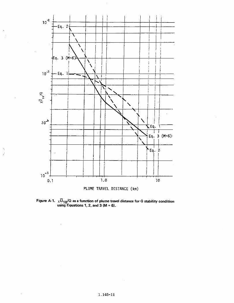
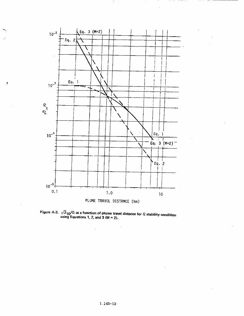
Figures A-1, A-2, and A-3 show plots of XU10 /Q (X/Qmultiplied by the windspeed U1 )versus downwind distancebased on the conditional use (as described in regulatoryposition 1.3.1) of Equations 1, 2, and 3 during atmos-pheric stability class G. The variable M for Equation 3equals 6, 3, and 2 respectively in Figures A-1, A-2, and A-3(M is as defined in regulatory position 1.3.1).
In Figure A-I, the XU, IQ from Equation 3 (M=6) isless than the higher value from Equation 1 or 2 at alldistances. Therefore, for M = 6, Equation 3 is used for alldistances.
In Figure A-2, the xU1 0/Q from Equation 3 (M = 3) isless than the higher value from Equation 1 or 2 beyond 0.8km. Therefore, for M = 3, Equation 3 is used beyond 0.8km. For distances less than 0.8 kin, the value from Equa-tion 3 equals that from Equation 2. Equation 2 is thereforeused for distances less than 0.8 km.
In Figure A-3, the XUIO/Q from Equation 3 (M = 2) isnever less than the higher value from Equation 1 or 2.Therefore, for M = 2, Equation 3 is not used at all. Instead,Equation 2 is used up to 0.8 km, and Equation 1 is usedbeyond 0.8 km.
1.145-10
1 02
10-3 Eq. I I 1....I i I I_ _
A I.
,10_-4. _X ___ _ H ____
_ _ __ _ x EEq. 1
= = --- Eq. 3(M=6)
I 1Eq. 2
1 0
0.1 1.0 10
PLUME TRAVEL DISTANCE (km)
Figure A-1. xU1O/Q as a function of plume travel distance for G stability conditionusing Equations 1, 2, and 3 (M = 6).
1.145-11

10
1 0
0*0
10 =q.
0.1 1.0 10
PLUME TRAVEL DISTANCE (km)
Figure A-2. xU10/Q as a function of plume travel distance for G stability condition
using Equations 1, 2, and 3 (M = 3).
1.145-12
102
4 I10-5 ; i
Eq. 3 (M=2)
0.1 1.0 10
PLUME TRAVEL DISTANCE (km)
Figure A-3. xU1j/Q as a function of plume travel distance for G stability conditionusing Equations 1, 2, and 3 (M = 2).
1.145-13
REFERENCES
1. I. Van der Hoven, "A Survey of Field Measurementsof Atmospheric Diffusion Under Low-Wind SpeedInversion Conditions," Nuclear Safety, Vol. 17,No.4, March-April 1976.
2. G. E. Start et al., "Rancho Seco Building WakeEffects on Atmospheric Diffusion," NOAA TechnicalMemorandum ERL ARL-69, Air Resources Labora-tory, Idaho Falls, Idaho, November 1977. Availablefrom Publication Services, Environmental ResearchLaboratories, National Oceanic and AtmosphericAdministration, Boulder, Colorado 80302.
3. R. B. Wilson et al., "Diffusion Under Low WindspeedConditions Near Oak Ridge, Tennessee," NOAATechnical Memorandum ERL ARL-6 1, Air ResourcesLaboratory, Idaho Falls, Idaho, 1976. Available fromPublication Services, Environmental Research Labora-tories, National Oceanic and Atmospheric Administra-tion, Boulder, Colorado 80302.
4. J. E. Sagendorf and C. R. Dickson, "Diffusion UnderLow Windspeed, Inversion Conditions," NOAATechnical Memorandum ERL ARL-52, Air ResourcesLaboratory, Idaho Falls, Idaho, 1974. Available fromPublication Services, Environmental Research Labora-tories, National Oceanic and Atmospheric Administra-tion, Boulder, Colorado 80302.
5. Gulf States Utilities Company, "Dispersion of TracerGas at the Proposed River Bend Nuclear PowerStation," Preliminary Safety Analysis Report, Amend-ment 24, Docket Numbers 50-458 and 50459, 1974.
6. Metropolitan Edison Company, "Atmospheric Diffu-
sion Experiments with SF Tracer Gas at Three MieIsland Nuclear Station Under Low Wind SpeecInversion Conditions," Final Safety Analysis Report,Amendment 24, Docket Number 50-289, 1972.
7. F. A. Gifford, Jr., "An Outline of Theories of Diffusion in the Lower Layers of the Atmosphere,'Chapter 3 in Meteorology and Atomic Energy-1960(D. H. Slade, Ed.). Available as TID-24190 from th(National Technical Information Service, SpringfieldVirginia 22151.
8. F. Gifford, "Atmospheric Dispersion Models fo)Environmental Pollution Applications," Lectures orAir Pollution and Environmental Impact AnalysesAmerican Meteorological Society, pp. 35-38, 1975
9. W. H. Snyder and R. E. Lawson, Jr., "Determinatioiof a Necessary Height for a Stack Close to a BuildingA Wind Tunnel Study," Atmospheric EnvironmentVol. 10, pp. 683-691, Pergamon Press, 1976.
10. D. R. Muller memorandum to H. R. Denton, "Meteorological Model for Part 100 Evaluations," July 251978, and August 2, 1978 reply.
11. 1. Van der Hoven, "Atmospheric Transport aniDiffusion at Coastal Sites," Nuclear Safety, Vol. E
pp. 490-499, 1967.
12. International Atomic Energy Agency, "AtmospheriDispersion in Nuclear Power Plant Siting-A SafetGuide," Safety Series No. 50-SG-S3, Vienna, Austria1980. Available from UNIPUB, 345 Park AvenuSouth, New York, N.Y. 10010.
1.145-14

UNITED STATESNUCLEAR REGULATORY COMMISSION
WASHINGTON, D.C. 2D555
FIRST-CLASS MAILPOSTAGE & fEES PAI
USD RCWASt. 0. C.
PERMIT No.. SjLj.
OFFICIAL BUSINESSPENALTY FOR PRIVATE USE, $30O