
Rev 5 to Procedure QI-QP-11.0-1, 'Cadweld Insp Activities.'
23
. , •.. . \ .. ,. , .... . - ..... . ' . . . . . ... •· . ( .. TEXAS UTILITIES GE_NERAT'ING CO. .. CPSES • TUGCO INSTRUCTION· .. · QI•QP-11.0·l Rev. 5 Page ·i. of 22 SEP 24. 1g94 CPDWELD INSPECTION ACTIVITIES ,., PREPARED:§E --=-= :;/ ' APPROVED BY: /(,£,,yA- j . APPROVED BY: .· Ak..R'l. bate 1.0 REFEREtCES 1-A Specification 2323-SS-ll, "Cadweld Connectors for Rein- forcing Steel 11 1-B B&R Construction Procedure, 35-1195-CCP-19, 1-C Procedure cP .. QP-16.0, 11 Nonconfonnances M Z.O GENERAL 2.1 · PURPOSE ... To describe the QC inspection and testing methods for mechanical splicing of reinforcing bars using the Cadweld Rebar Splice Method. 2.2 SCOPE To control methods for qua11f1catfon, requa11f1catfon, fdentiff- catfon of splicer and cedwelds, production records, cadweld inspection, and samp 11 ng &nd testing • 8512020580 851106 PDR FOi A QARDE85-59 PDR
Transcript of Rev 5 to Procedure QI-QP-11.0-1, 'Cadweld Insp Activities.'

. , •.. . \
.. ,. , ....
. - ..... . ' . . . . . ~ ... •· .
( .. TEXAS UTILITIES GE_NERAT'ING CO.
.. CPSES • ~.· TUGCO INSTRUCTION· .. · QI•QP-11.0·l Rev. 5 Page ·i. of 22
SEP 24. 1g94
CPDWELD INSPECTION ACTIVITIES ,.,
PREPARED:§E --=-= :;/ '
APPROVED BY: ,~~ /(,£,,yA-~ j .
APPROVED BY: $e:~-u:?2.o. .· Ak..R'l.
.9·'1-~1 bate
1.0 REFEREtCES
1-A Specification 2323-SS-ll, "Cadweld Connectors for Rein-forcing Steel 11
1-B B&R Construction Procedure, 35-1195-CCP-19,
1-C Procedure cP .. QP-16.0, 11Nonconfonnances M
Z.O GENERAL
2 .1 · PURPOSE ... To describe the QC inspection and testing methods for mechanical splicing of reinforcing bars using the Cadweld Rebar Splice Method.
2.2 SCOPE
To control methods for qua11f1catfon, requa11f1catfon, fdentiffcatfon of splicer and cedwelds, production records, cadweld inspection, and samp 11 ng &nd testing •
8512020580 851106 PDR FOi A QARDE85-59 PDR

.. 1.:.··:· ...... :.·:.. ' ~~T .... : ··.-. •.:. ·; , ·-· . \'i.:~·:. ' ... ::.:.~ ... ., . .:·
·., ·.· .. ·: ..
.. ·, .. ."• ·.
< ., .~
{
\
TEXAS UTILITIES GENERATING CO~
• CPSES -
TUGCO INSTRUCTION QI-QP-11.0·l Rev. 5 Page·2 of 22
SEP 24 1984
3.0 INSTRUCTION
3.1 QUALIFICATION OF CADWELD SPLICERS
3.1.1 Training
Verify fran attendance lists for cadweld splicing training sessions that each prospective cadweld splicer has received training fran an Er1co representative or by Erica-qualified personnel in accordance with Reference 1-B. This training must be administered in each splice position in which the prospective cadweld splicer is to be qualified prior to preparation of qualification splices.
3.1.2 Qualification
a. After the training session. the proposed splicer shall prepare two splices for each position that he 1s qualifying for:
NOTE: Bar size 118 Test Splices qualify for al 1 bar sizes.
b. The QC Inspector shall visually inspect the canpletedsplices in accordance with paragraph 3.4 and docunent re5Ults on the Cadweld Spltcer Qualification.Fann (Figure 1).
c. If the splices are detenn1ned by the QC Inspector to be visually acceptable, they shall be tensile tested in accordance w1 th Reference 1-A and the results docwnented· on the Cadweld Splicer Qualification Fonn (Figure 1).
d. Upon receipt of satisfactory \tensile test results, the qualified splicer shall be issued a unique I.D. symbol to be used as part of the identification for 111· of his future splices. An example of a typical splice sleeve identification 1 s •ABH2P• where:
2 -,
Is the splicer's I.D. symbol
Denotes that splice was shot in the horizontal position (V-Vert1ca1 or D-Diagonal)
Denotes the second splice for the splices in the horizontil · position for this particular blr s1ie.
Denote a Production Test Splice (S·Shter Test Splice or Q-Qualification Test Splice).

{ .···
·,·,'
•
; •. . \ .
:·• ::.·.. . ··~··'
., ··' .. . . (
TEXAS UT lLITIES GENERATING CO.
• CPSES -
TUOCO INSTRUCTION Ql·QP·ll.0-1 Rev. 5 Page 3 of 22
e.
SEP 24 1984
The splicer's I.D. symbol, name and_ badge n1111ber shal 1 be entered in the Cadweld Splicer Qual1f1cat1on Status Report (Figure 2) by C1vil QC Personnel to reflect the splicer's current qualification status.
In addition, the QC Inspector shall sign and date Line 7 on the Cadweld Splicer Qualification Fann (Figure 1) to denote:
1) that the verification of training (Para. 3.1.1) in the applicable splice position has been perfonned and
2) that he has verified that results of vhual inspect ;ons and tensile tests of the qualification splices are satisfactory.
3.2 REQUALIFICATION
3. 2.1 Conditions for Reguali f1cation
a. If the position (Horizontal. Vertical, Diagonal) has not been used for three nonths or 111>re, or
b. If cmnpleted splices fail to pass vtsual inspection. It is not necessary to requalify a splicer on the basis of a single visual reject. but consistent v1 sual rejects by the QC Inspector shall be cause for requa11fication, or
c. If cmnpleted splices fail to pass the tensile tests (1.e •. failure rate exceeds one failure 1n 15 consecutive tensile tests), or
d. if there 1s another reason for the QC _Inspector to question the splicer's ability. ·
3.2.2 Method of Requalification
3.3
3.3.1
The method of requal 1ficaticn shal 1 be identical to the original qua11ficat1on procedure for the applicable splice position.
INSPECTION RB)U1R94ENTS FOR SPLICE SET-UPS
Frequency
The QC Inspector shal 1 perform randClll inspect ions . of the preparation and set'."'up of Cadweld SpHces during each shift in which cldweld1ng is performed.
------"---"--"---"-------~------"-------·---- - - ·- -··- -

,., .....
.. .1 •. 1\, .
':-.,
'. ••'' '.
·, ...
I -~-·~
TEXAS:. UT IL'ITIES· GENERATING co. • CPSES .. ·
~ : ~~
TUGCO INSTllJCTION QI-QP-11.D-l Rev. 5
.. Page 4 of 22 ·
SEP 24 1984 .
3.3~2 Cadweld Splicer !)Jal1f1cation
On those splice· set-ups observed, the QC Inspector shall verify that each splicer is currently qualified 1n the splice pos1tio11 and b& r s 1ze to be used.
3.3.3 Cleaning
a. On those splice· set-·ups observed, the QC Inspector shal 1 verify that bar ends are properly cleaned by heat1 ng and wire brushing to remove all loose millscale, rust, moisture, etc,. In additfon, prior to splice set-'up the QC Inspector shall verify that al 1 rust and foreign matter are raved fre111 the sleeve 1.D. and that the sleeve is heated with an oxyacet;ylene rosebud torch to ensure removal· of 111>hture.
b. If hand wire brushing is used, the bar shal 1 be heated and brushed twice, then wiped w1 th a clean dry cloth to ranove dust •
c. The bar ends shal 1 be cleaned a di stance equal to Is the sleeve . length + 2 1 nches.
d. When either the •b1ent temperature is 32° For less .!U:. the relative humidity is above 65S, the QC Inspector shall verify that the splice sleeve 1s dried by preheating after all · materials and equipa!nt are in position and illlllediately prior to pouring the filler powder fo the crucible.
3.3.4 Reference Marts
a. On those splice set-ups observed, the QC Inspector shall verify that reference marks are placed on each piece of rebar a distance of 12" :1: la" fre111 the bar end.
b. The marks shall be inscribed in the reblr rib with a draw file, preferably prior to putt1ng the sleeve on the bars.,
c. If the bars must be marked after the sleeve 1s centered, the QC. Inspector shall visually check the bar end locations through the.tap hole before the marks are·added.
·· d. If for same reason the ina rtts cannot be located at 12• t' Ii" fram the bar ends, the QC Inspector shall verify sleeve centering by looking through the tap hole. The QC Inspector shall docu•nt the location of the marks (if other than at l~ t i.•) · for future. reference on the Cadwl d Sleeve lnspect1ori Record (Figure 3).

' ..
·•(A· \ ..
TEXAS UTILITIES GENERATING CO.
• CPSES -
·. (,.
TUGCO I ~s TRUCT r ON QI-QP-11.0-l Rev. 5 Page 5 of 22
SEP 24 1984
e. If the. i211 reference marks are on the bar end and it is necessary to change the marks (prior to igniting the splice). the QC Inspector shall verify the nE!W mark location fran the bar end. He w111 then require the splicer to peen out the original mark wfth a hmnner.
f, Removal of the reference marks by peening al so applies when it ; s necessary to trim the bar ends after marks have been placed on the bars.
3.3.5 Positioning of Sleeve
a. When inspecting the position of the sleeve for centering, the QC Inspector should be able to see the gap between rebar ends through the tap hole. On vertical set-ups the gap shal 1 be 1/811
- 3/1611 (using 1 spacer) and a maximum of 3/811 on horizontal or diagonal set.ups.
b. The QC Inspector shal 1 verf fy that asbestos pack1ng 1 s installed in sleeve. ends and that sleeve end· al igmnent Clamps are properly installed (i.e. sleeve 1s centered concentric with the bars and packing is seated properly).
3.3.6 Filler Metal Powder Cartridge
a. The QC Inspector shall verify that the sleeve and filler metal powder cartridge to be used are the proper size for bars to be spliced. In addi t1on, he shall verify that filler metal powder 1s remixed immediately prior to use.
~
3.3.7 Ooct111t11tation of Splice Set Up Inspection
The QC Inspector- shal 1 document inspection of splice set-up or preparation on the Cadweld Sleeve Inspection Record (Figure 3).
3.3.8 Inspection of •e• Series Splice Set-ups
ln add1 t1on to canpl@ting tj.e Cadwel d Sleeve Inspection Record (Figure 3), the QC Inst.'!lctar shall c<111plete the Inspection Report (Figure 6) for those •it1 Series Splice Set:..ups observed.
3.4 INSPECTION OF CCl4PLETED $PLICES
Each canpleted splice shai.1 be inspected by the QC Inspector in accordance with the follow·fng criteria:

' _i.·
.......
(
TEXAS llTil.ITIES GENERATING CO.
··CPSES -
TUGCO INSTRUCT ION QI-QP-11.0-1 Rev. 5 Page 6 of 22
SEP 24 1984
3.4.l Reference Marts
3.4.2
a. The QC Inspector shal 1 inspect each spHce for proper sleeve centering by using reference file marks provided on the rib of each piece of reba r.
b. The reference file marks are placed on the rebar by the splicer during the set-up operation.
c. The QC Inspector shal 1 measure the di stance fran mark to mark, locate the midpoint of that di stance, and verify that the center of the tap hole ;s located within ± '5" of the midpoint.
d. MaxilllJlll allowable distance betwe~n marks is 24 7/a•. Minimum allowable distance between narks is 23 11/16". These tolerances are based on th,. reference marks befog 12" ± '&" f ran the bar ends •
e. If a ccinpleted splice fails to meet any of the criteria in 3.4.1.a through 3~4.1.d, the splice shall be rej~cted.
Tap Hole Inspection
a. The QC Inspector shal 1 inspect the tap hole of each canpleted spl 1ce for the presence of good f11 ler metal ,slag, or porous metal.
b. The inspector can detennine that the material 1n the tap hole 1s good filler metal if it shines after being hit with a hammer.
c. Slag is hard, brittle, ceranic type material with 1 flat chalky gray color. It will shatter when hit with a hammer.
d. Porous metal will have a pt\)'sical appearance similar to sponge. A single shrinkage bubble in the tap hole should not be confused with porous metal and ·is not cause for rejection.
e. If the QC Inspector should determine that slag 1s in the tap hole, the slag shall be removed~ If it is detennined that the slag extends beyond the 1ns1de d1.-neter of the sleeve, that -1 nspector sh111 reject the sp 11ce.

',;
:.> ·.: .. ~·: ·:. ·:-;.~ .. ; ... ·_,...' ';,;' .·, ;;r· •
•
••• •i'· ..
.... ···::_., ·.,'I
'. '. ·- c TEXAS llTlLITlES GENERAT[NG CO.
• CPSES •
~ ·~
(
TUGCO . INSTllJCTION QI-QP-11.0·1 Rev. 5 Page 7 of 22
SEP 241984
f. If the slag 1 s ranoved fran the tap hole .and good filler metal 1s discovered before passing beyond 'the inside diameter of the sleeve, the splice shal 1 not be· rejected for slag in the tap hole. ·
g. Al 1 slag lll!St be ranoved frClll the tap hole before accepting the splice.
3.4.3 Inspection of Sleeve Ends
a. Each access;ble end of each canpleted splice shall be inspected by the QC Inspector for excessive voids, low fill, porous metal, and slag.
b. Void area shal 1 be determined by using a short piece of tie wire to neasure the depth and a standard steel tape to measure the width.
c. The void width shal 1 be measured at the bar and the void depth shall be detennined by the deepest point of the void. The void shall be.considered rectangular ;n shape.
d. Excessive low fill shall be calculated by the same method used for voids.
e. If a splice has both low fill and spot voids, the area shal 1 be added for a cu11Nlative total of void area.
f. The QC Inspector can use the chart (Figure 4) as an aid for calculating the spot void and/or low fill 1re1. · .•
g. The QC Inspector shal 1 use the Cadweld Manufacturer's criteria (Figure 5) for acceptance or rejection of a spot void or low f111 area. Void area in a sleeve end which is greater than the allowable void area in Figure S shal 1 be cause for rejection of the applicable splice.
h. Porous metal or slag in a sleeve end shall be cause for rejection of the applicable splice.
1. Sound splices often have pin holes, shrinkage fissures, and cold joints visible at the ends of cCJnpleted splices which are not cause for rejection. · ·
. . . .~.

•:. 1: .. . ~: . - ·.~· ·.:.
\. . • ,
' . ' ..
. . . ~
TEXAS UTILITIES GENERATING CO. TUGCO INSTRUCTION QI-QP~ll.0-1 Rev~ 5 Page 8 of 22 - CPSES -
SEP 24 1994
3.4.4 Inspection of "B" Series Splices
In addition to ccxnpleting the Cadweld Sleeve Inspect;on Record (Figure 3), the inspector shall use the Inspection Report (Figure 6) for the inspection and documentation of "B" Serie·s splices.
3.4.S Cadweld Acceptance
3.4.6
a. Prior to splice acceptance the QC Inspector shall verify that sleeve identity markings are leg;ble and that splicer ident~fied thereon is currently qualified in the applicable position.
b. The QC Inspector shall apply a white acceptance stripe to each splice inspected and found to be satisfactory.
c. The Cadwel d Sleeve Inspect fon Record (Figure 3) shal 1 be used.to docunent inspection of satisfactory splices.
Cadweld Rejection
a. The QC Inspector shal 1 apply a yellow rejection stripe to each splice inspected and found to be unsatisfactory.
b. A rejected splice shal 1 be cut out, ranoved fran the area and shal 1 not be .used for tensile testing purposes.
· c. The Cadweld Sleeve inspection Record (Figure 3) shal 1 be used to doculll!nt the inspect1o~ of a rejected splice and shall indicate the reason for rejection.
3.5 TENSILE TESTING OF CCl4PLETEO SPLICES
3.5.1 Sampling and Tensile Testing
a. The QC Inspector shal 1 select the location of production and sister splices for tensile testing to maintain the frequency requ1renents. (Reference 1-A Para~ 7.7.1 & 7.7.2).
b. Sister Test s1111ples shall be substituted for Production Simples for. •r series splices "91ded to embedments and ~e• Series . aftchOrlge splices '9f1ere the COnfigUrltion doesn It al low for Production sa:nples •
L,....,;......,;.~....,,;;,.-;.;.. __ _;__..;...;..;__;._....;,___._;__ ____ ___;_ __ - ___ __;__ ________ ~_ -- -· -·-

. :·:.• ·· .. , .·
. ,.,. · .. ···· '';.:._« . .,._.:;.
•
.,. ..
;.,. t .
"'·,
( .. ( . .. .
TEXAS UTILITIES GENERATING CO.
- CPSES • ~ · TUGCO INSTllJCTION QI-QP-11.0·l Rev. 5 Page 9 of 22
c.
d.
e.
f.
g.
SEP 24 1984
On· tightly curved bars (as detennined by the. responsible Civil Quality Control Level II Inspector) Sister samples shall be made in 11eu of Production samples and the sample frequency shall be as noted in Reference 1-A Para. 7. 7. 2.
All other test samples shal 1 ~ Production splices ranoved per the frequency nQted in Reference 1-A Para. 7. 7 .1.
The QC Inspector ma.y use the Daily Test Status Report {Figure 7) as an aid to dr:;tenn1ne the next applicable test for each splicer, positio .. and bar size.
If a test 1s required, the QC lnspec~or shal 1 check the appropriate blank on the Cadweld Consecutive Splice Record (Figure 8) under "Test" {P-Production, S-S1ster}.
The QC Inspector shal 1 not notify the splicer of a Production Test until after the splice is completed.
h. If the requirenent is for a Sister splice, the QC Inspector shall notify the splicer that a sample will be required immediately after the one that the splicer is currently setting up.
1. Test samples shal 1 be identified by the QC Inspector with a red stripe and docurrented on the Cadweld. Sleeve Inspection Record (Figure 3) i 11 P11 for Production and •s 11 for Sister.
j. The test splice shall . be removed by B&R Constrt!ction and subsequently delivered to the 51 te Testing Lab by QC personnel for tens11e testing. '
3.5.2 Reporting
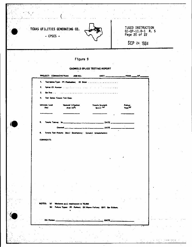
a. QC personnel shal 1 canplete items 1,2 and 3 on Cadwel d Splice Testing Report (Figure 9) for each splice tested and submit to Site Test Lab, l-:i11ch will perfonn each test and rewrn completed report h the responsible Civil Qua11 ey Control Level II Inspector for QA rev1 ew and signature.
b. QC personnel sh411 l:nter the results of 111 Product1'on and Sister splice tensile tests in the order in which they are tested on the· Cadweld Splice Tensile Test Average ·Report (Figure 10). Canpleted reports shal 1 be submitted to the Permanent Plant Records Ymult {PPRV). Either of the fol lowirig condi t;ons shall be cause for the issuance of a noncanfonnance report in. accordance w1 th Reference l· C and the imnedhte stoppage of further Cadwel ding 1ctiv1 tfes: ·
I I

'·,'•' .:. ..... :·
·· ... , .: . ·~ .
·'•
··.1,.··.
( .. ·~· .
TEXAS llTILlTlES GENERATING CO.
• CPSES •
f ( TUGCO INSTRUCTION QI-QP-11.0·l Rev. 5 Page 10 of 22
SEP 24 1984
1. If the. results of mre thin one in any· 15 consecut 1ve individual tensile tests are less than 75,000 psi.
2. If the average of any 15 consecutive· tensile test results is less than 90,000 psi.
c. QC personnel shal 1 perform the tadweld. 90 Day Rev1 ew (Figure 11) and submit to the Penrenent Plant Records Vault (PPRV).
3.6 MAPPING SPLICE TEST LOCATIONS
Each splice location on the Conta1rwnent .al 1 and done shall be located. by QC personnel on 1 record drawing prior to anbednent of applicable splice in concrete. Infonnation shal 1 include test splice locations and n~bers on the record drawing.

..
,, •.... .. ,.
.ii-.::· ·.•.'; ·.•· ..
.· (. I
t.
TEXAS UT ILITlES GENERATING CO.
• CPSES •
TUGCO INSTRUCTION QI-QP-11.0·l R. 5 Page 11 of 22
SEP 24 1984
Ftgure 1
'AGl-O•-'- ........... ____________ .......... ___ ....,. __
I
..
1&11:,,, . ...,, 0 ... ------------
y.__ ._"'ii -....1111 See ~ 3.4
NMo. JI ·&.ct. ..... ,,.3 ..
fO
,_ . .......,. .... .1.tll
._... ................ ___________ -.a.1 .
, ... , ..... .,. ____________ O..: ___ _
a.-.. _____________ o...: ___ _
1. Oa'll
a...rc:..... ________ ,__ ___ .,..; ___ _
~llTI:
NUJU. •· .l.:a ,..,.,._1111 ................. ," •""""""· ........... ~ .......... 11.-,.u .. ..... , ...... .w.-: "' .............. "'' ........

••••
,•
(.
TEXAS UTILITIES GENERATING CO.
- CPSES -
TUGCO INSTRUCTION QI-QP-11.0-1 R. 5 Page 11 of 22
SEP 24 · 1984
Figure 1
CADWILD SPLICER QUALIFICATION
'· ............. _____________ ..... No.------2. B&PSol-1.D .. No. ___________ _
T1Mil1
''""'"'
Viloill
•....-iA-.. loi/l llejMt ClCI See ~3.4
• 111.t.1.1"
5. ,. .. ,.u..-.ftnnllll ..... •·------------ p.aJ.
I. TlftllleT•~ ""-------------·Dita: ___ _
Fllilw9 Tvor
Oledlod _____________ o.te: ___ _
CJuellly CoMNI o.; ____ _
COMMENT$:
NUTH. •· 1.a"'*'f ...... llC~ 1111 ••11 ""'°'· .., . .,;....-......a. ............ 71.~,, ....... .. , ..... ,,,. •i ,.._.; Ill ··-••ii-: ,.,., .........
•''···I";; 1'·•.:··

·:,•·'·
.•
••
.·.,···· · .. ·;.• .
. . .
.• (
TEXAS·UTILITIES GENERATING CO.
. • CPSES •
Figure 2
TUGCO INSTRUCTION Ql-QP-11~0~1 R. 5 Page 12 of 22
SEP 24 1984
CADWELD •LICEA QUALIFICATION ITATUI HfORT
""''---· PAOl_OI ..;,__ U&UAC&11u,. lil&IUl
SPLICEll'S SPLICER'S IPLICER"S •no 110• 1a1· ~--~ .... l.D.NO. NAME IADGEND. QC ClC ClC
DATE INITIAIJ DATE INITIALS DATE INITIALS
I
I
I I I
i
;
'•
•NUTll:
-

·;',
.
. . ' --
.
••
( ·.
TEXAS UTILITIES GENERATING CO.
• CPSES
-
TUGCO INSTRUCTION QI-QP-11~0-l
R~ 5 Page 13 of 22
·
PJ ' ' ... .., c ~
SEP 24· 1984
Figure 3
I I I I I I I I I I I I I I I I I I I I
. I ,
as 11
11 1
11
11
I I 11 11
I 11 I I
.. -q
er: .
l _,_

. . . ' . .
.. :····.
' . -~ ·.:
'.. ~· ·.c TEXAS UTILITIES GENERATING CO.
• CPSES -
TUGCO INSTRUCTION QI-QP-11~0-l R. 5 Page 14 of 22 .
SEP 24 1984
Figure 4
WIDTK
! . . II ~~ ~ '·:'~' ~-:~~ ~-~·I 1·1/Z 1·5111 1·31•1 1·7/1 I 1·1/1 1•1/4 1•3/1 1·1/Z Z•S/I Z·3/4 Z·7/8 1 ....... 1 .• j •••• . •. 2 l 1.22 1.32 11.'2 1.52 1,63 1.73 1.113 1.93 Z.03 2.13 2.2J 2.?4 2.u
1-:1s' ,g, I :.:is 1.11 1.29 1,c1 i.s2 I.fie L7fi · 1.as 1,n 2.11 2.23 Z.35 z.4& 2.58 2.10 2.a1
1·1/• 1.05 1.19 1;33 1.46 1,5!1 1.12 1.86 1.99 Z.12 z.zs 2.39 2.sz z.ss Z.78 Z.92
1·3/8 l.19 1.34 1.49. 1.64 1,7!1 1.93 Z.OS Z.ZJ Z.38 Z.53 Z.U Z,83 Z.ta
l·l/2 1.31 1.'7 1.54 1.80 1.17 2.13 Z.29 2.46 Z.62 2,71 Z.!5
:::t 1-5/IJ 11.4' i 1.52 1.80 1.98 2.16 2.J4 2.52 Z.70 2.18 •~--t·-------1----;.--....... ---+---0.---1-----1----' ! i·Jf( j 1.55 j 1.16 1.96 2.15 2.34 Z.54 . 2.73 Z.93 I ~--"f---+---+---+---+----+---+---.+---.-1 1 1·7/! 1.69 1.90 2.11 2.32 2.54 2.75 Z.96
z I u1 2.0• 2.26 2.49 z.12 z.~
CADWELD VOID MU 2-1/8 ! I. 94 2.18 Z.43 2.67 2.9l
2-11,i 2.0& · 2.32 z.sa z.Bl. ---------:-:LOV::F'IL'L AREA z.3/8 I 2.l9 Z.C6 2.74
M/2 2.31 2.60 Z.89
2·5/B z.ca 2.75 .443 .371 .313 .250 .118
Z•3/& 2,55 z.aa z.7/1 2.59
J 2.01
D E p T H
5/11 .IH .75 .'26 ,500 ,376
3/1 1.33 1.13 .939 .750 .SM
7116 1.11 1.50 1.25 .752
1/Z z.zz 1.11 1.57 1.25 ·" !Utll Z.H Z.ZS 1.U 1.5 1.13
5/1 3.11 2.53 z.11 1.75 1.32
NOTE: Add antwrt f ... llatll Clll"'I II nllded,
.125
,15
.375
.s .525
.75
.875
• ·3/11 for pack1ns hit 11re1d1 been f19ul'ld in botll chlrt1
.0'3
.125
.188
.25
.31
.375
,438
, ... ·

••
••
·.-le.. ··.;····
.· (·. (
. \ ..
TEXAS UTILITIES GENERATING CO~ ~
~ TUGCO INSTRUCTION QI-QP-11.0-1 R. 5 Page 15 of 22 • CPSES ~
... SEP 24 1984
Figure 5
·'1' "·-: :"' ...... --:". r.;, .• i.ia..- •PLll:llii.
I ...................... ~ .. --------.......... . void ·limits· V9'd - ire •111 • ....... .._..In .................. .-a.- .... will
~-=:-._..IM_....,..._~.
r I :-r:-V.WAI• h ,.--, ... •-CM.•• -·- .. , ... •••• .._. Cal•-& -·--- . _L_ - - I .... !"'•t:.'b CIHVM••· ... ~
notes: (;\Aflttw1blt HCllfPIUllli.,. •tPtl ,; 111ot111rn le11 rich wnd. 'Ot •• · ~ • •Pli<w ol 11'8 W"' t1•1.1n1 d -•""""•ii"• .., wMI Fil' ..... ,,. ...
- ,,, . I •• , ... 011 "' ! OU .. ,, •lf•·t!Oll ·Ml I OUllllJ
• • I llT.llOIC·MI I OH . '" llTl·llOll·lll '""·°' •• ltf .. IOIC•lll I , ... • •n lllTl·JIDIC•MI ••11.m ,,, llT • 71011 •MJ I
,.., . "' .. " .. 1011·111 Ulltl.OZ
ti I .. ,.,,.,, ... , Ull . ,,. llTl·llDll·MI 1.n11 DI
•• 11t.:"lf· 0•• I -"' , .. ,.,,;"·~· ,, l.01
" '"o .. Ct·•··•···•·lll .ttll ... ·H11.;.c '•1·111 I 1.0Jll OJ
•'0 llC 101IC•NI I ... IH -IDtll·MI UIJ 111-IDIDll·HI I I.II
•10/11 llC:lll·lllOC·MO IOJ/1 OJ llflD·ll 1014-'ll Ultl ~l
"" llC·ll71( 0 HJ lllJ IH•lllOl(·HI 1.U
tllltl• HClt.t•lll·MI l.Dlltl.J• ltftl•UIOll·MI l.IJll.11 ,.,,.,,. llCll • 11111 ·MI 1.IJIUO llfllolllOll•NI l.IJfl ... ...
I llC•Ull(oHJ I ,,. HC·1•1ll•MI UJ llT.1•Nl 0 H1 UI llT•UIOll·MI J.11 ... ,,. llC:ta.11'-l•NJ u11uo llTl••lllOll•MI J.11/1.ft ... I llC·lllll·MI .... RIC•llJll•MI W
m:m11::1 = '-·
.. ., .. • 'llotll II . ,. ..
"''. II .,. • • .,...
llllo
"' 'llo • 'llot'llo
""" 'llo .. 'llo/I
"''" 'llolllo llol II
'llo • • • .,. .,. • ... "' • ·---" ._ _.,. '
olld'Mo" lltwlffil_,,__., • . ;,, ,..,.._ '1 /W, (C,,,,..,. """9llOid-•11' • (IW.-1'.) + ~~·(7.09-11'1 • 2.66 oqtlM itfdiel), 1M
rftOI (WJ al .,,.,woid ·-· fllff ., lhl IHI ,,.,,,,,.,.,,
(!) UM W. c°"""" .,,,, Ill 6UIHIMI 1p/lc11: wttiul. heti· -L -ilonut rill• lilJ. M· ,,1.d 1pliu1 1nd B·HtiH S11uer111• $pticN ,.,,,. 1pot '#/di. @ u.. rJi;r c.u.. ,,,,. Wlficlll
.... ..i, . wilfl """ lilltt
""'-' .,_,,, """ '"-• f-CI (IOI lpO# Wliill. - ....... CoAlmnAJ,A#fiU6/• #rtlf11t' w1tlc1/ • •Hti•• St1uctu1• Well .,.;,11 low ,.,., _,., "°""" .,,, .. ~ NOrE: Void ~ un ..~.,-.,. ,,,....,,. .......
_ .• ...!!.'~'!.!;~l ----':!"·-···--• ...,.,__ ... .,.........,. _____ ......, .... ,..,.111. ·1'1.-.. ,,.,,,, .. ,.
void llmlts-C-t6 series compression only splices ~ Jiiiy llllicll lhaH bl~ wlWl9 Mid ,._ 111t..C ii Ill .,._. 11 , ... Splice SIMwe TIO Hol1. lltld .... ••• llO ...,.. ,,..,. ' Inch, ....... lllOI Wide • lull circuMIMntlal '°"' foU.
....... ,..
summary -·· .. _, ......
TM IMpeaioll of I CAOWILO 11.- llllice II -.1 . . OccMlanll .cMcWne °' 1111.--llWMlllll ol llMI llPlicar ·~ llllM W119lflll hi h lollowlfta die _.Cl lllliCiflO PIOC*l-wlll - io relnlooce the iud9-• ol ,... IMOICw. on the jib. lliCCJ llllllllld illllluclionl •hOuld ... ......... .. mldlliOllll lnllli..-

. 'i -~ . . : :_ ' , .....
,:.
,(A. ,.
. .•
.' :·.
.
(
TEXAS UTILITIES GENERATING CO.
• CPSES -
M
Figure 6
s ... llllP!CTICIN REPORT
··---- J --·•e• Sertes Cad~elds
-- I
i-j , ..... , •• "_,_
TUGCO INSTRUCTION QI-QP-11.0-1 . R. 5 Page 16 of 22
SEP 24 i984
- ' I
• ~- ,l"'H• • !;;'; ..... -. e qy. I .._ !'!Cl. 1~ UJlll •a•• •YMIH" •v•--. •ill-
-OP-I I 0-1 llf'v ... • 01·~ CJ~~TIOll Cll'llT~,,_ I TIQtl CJ~Oll a~ • -1111111.TI
0 ~ ClllAl1ID, &L. ,... •er I .,_ IA,..,M:TGIW
c . ...,... ~ .... lllllC!'lllll' ,,.. US1D .... oc ~ oafi
"' ,,.... .. INIHCIHM
.. oc &T11UIUT'!S .. i O&TI c -~ .. ... I 12" rtfer .. nc111 1Mrk h •• ,.,.; •• .i ~i.-- ... ...._11f;nn •L"•"'
I to ........ 11-nt r~- ,1 ...... 1 ; ...... A I
2. No N!fil!rll'nCll! IMrk h· r .. oufrl!d wh .. n r .. hu• nau.r
though sleeve.(see ftqure 1, ftem Cl
'I "-·•#u •h•• A•--~1,. .. 'I I~ ------• •• "•• "-·· -•--
'·
I I I I
I I I I
I I I I I I
..... c-..m.rrc:J
... I_._ 'ICll .a, .. I UI. cu.Ill 0
llAft : ..... Nll'I I I. ec ._.,.CTQll •
Cl/01 8/84
. .... · .

'• . . . .
: ·! ...
- - (
TEXAS UTILITIES GENERATING CO.
• CPSES •
Figure 6 (Cont)
,_ NL ltUllUlliS, SU MIT I_
lftll INSP!CTIQN &tTIHUTIS -' "
. .
.. ·- ,,,.,~ .. .I.
C3D . .
!ID.
'•
-" : i
I
TUGCO INSTRUCTION QI-QP-11.0-1 R. 5 Page 17 of 22
SEP 24 1984
llATI e.c. -'NII
••. t!
J GOO . R A
[!I JYxxrxXXYXX~
~"· ...... . 'i" !~llllXXXV)('YY X' ~-y- X :i~
y _J .. -..TW lllC" .. ~1 U; CUllD- . . : . 11111: c ...... """ I ' IC WWWoa • Cl/Ol 1114
. .. ·~ .... ,:-• .. . ~ ........ ,, ...... .

. .
TEXAS. ur IL I TIES GENERATING CO.
• CPSES -
Figure 7
Daily Test Status Report
, .
TUGCO INSTRUCTION QI-QP-11.0-1 R. 5 Page 18 of 22
SEP 24 t9~4

i. .... . .: ·:
. i . . .
•
TEXAS UTILITIES GENERATING CO.
• CPSES •
Figure 8
··-TUGCO INSTRUCTION QI-OP-11.0-1 · R. 5 Page 19 of 22
SEP 24 198!1
CAD'lfUD ~LICEA CONSECUTIVI ~LIC:E RECORO
.. 0::1.':'1 CO"'"flCMI PlAIC ··=•--DE---cc·.~tcl ! '·-1;"""""' ~~
, ... ~ ........ r£Srl :;:i. I I
i·~·.~v. :J• ··:.·· . lO~:SEC .• llL1:l:. I- •11· i:.:.":"~ ~.;). ;;. Sue. , P !i j 1:0. 1 DO:.Tt tXJ. S· Sur. r I)
I l i I I
I I I I
~
I I I I
I I I I I I
.. I I I I i
i.;....-- i I I I l I
I .. I I
L I i I I ..
i . ! . ' ___ l.l. ---,-··-- I I ----.-- I
---.. -·- - ·----L--! .. ..__
~······ •• ·" ~~~: :;1!~ I .----~----·-·--· .... -_-_-·_· ---'~=~:. __ -. __ SPLICCR no._ L
·.:.·
(
TEXAS UTILITIES GENERATING CO.
- CPSES •
Figure 9
CAIMELD SPLICE T!STING REPORT
TUGCO INSTRUCT.I ON QI-QP-11.0-1 R. 5 Page 20.of 22
SEP 24 1984
"'Q.IECT: COMANCHI PIAIC .109 NO.: UNIT: _____ PAOl_O,_
1. TMt~T.,,r. IPI .......... : Ill Ii- ................. .
2. Scilim l.D. N""'- . , , .. , . . .. , . . . .
3. Bir Son . ,
I. r..-.1 • ..,.: "'-----------DATE _____ _ Clwdold ___________ DAT! ------
COMMENTS:
NOT!I: Ill ....,_ 111o1J. ,....._ II 79,000
C.I ,.._ -ry,.: Cl'I ......_: W.1 .,_ l'eil-: l•FI ._ , ......

. . . ' .
' ....• ,. . .· .. ' (
•
(
TEXAS.UTlllTIES GENERATING. CO.
• CPSES •
TUGCO INSTRUCTION QI-QP-11.0·l R. 5 Page 21 of 22
'
I I
SEP 24 1984
Figure 10
'lllOJECT: _____ _ JOI NO, ___ UIUT_ l'AGE___;oF_
i TEST SPLrCE TYPE
B&R SPLICE BAR PROD.(P) SISTER(S) l,D, NO, SIZE
F.ldl IY.1"11~ a~ H c:on11c11th• sw.=t11 . ("1nf1U1 of 90,000 ps1) SATISFACTORY __ _
Not ..,,.. ttian Oftt 1ncl1vfdua1 ttftlfle ltNf'lllttl tn 15 C0111ecUth1 1111 thin 75.DOO Pl f • SATISFACTORY
OUALlTY COHTRDL:
INDIVIDUAL AVERAGE OF TE?fllLE SAl~L~ :. ~:~~GTH PREVIOUS l,.
CO~SECrl'!E PSI .
I
UNSATISFACTORY_
UMSATISFACTORY
.. ~D _llY:. _____ ..._...__.... __ CHECKED llf:~------------btlt bAit
QA AlVIEW:. ___ ..._ ______ liA.itt-
-~,., .. · . ..,_.... ~ .. •.

...
.(. ·\,,
,(
TEXAS UTILITIES GENERAllNG CO.
• CPSES •
Figure 11
CADWEUI Ill DAT ~Vl[W
TUGCO INSTRUCTION QI-QP·ll.0-1 R. 5 Page 22 of 22
SEP 24 1984
-.Q· CPSES -1114 n.1m Ul':tT ___ ,ao,_ OP~
I R["l[U lllfEP.VAL: ·"-~• .. ~•h1,.ll ------ FJL£ 110. Ri:\'J£!!£D: ____ _ 1
I DAft Of lr.ITIALS SPLICER I mm1 OF !tEYIEWER ID .Y£RT. DATE: HDIUZ. DATE Dlt.GO:W. ...~ . • r .. '
' . I I I .. I I
I I I i
I I I -
I i I
: I
I I I
-· I i I -- I -- ,_. I I -·- I --· -1-- . I --·- - -I -.. - ' -
··-·- -- I --- I .. ' ·----· -·- ---- --- - ;
-
.. :·'