005-001-004-004 Royal Geographical Society - Gap Planning Toolkit
Report No. 42074-R-004
SEISMIC VERIFICATION OF BATTERY CHARGER 21 AT INDIAN POINT UNIT 2
September 23, 1991
Revision 0
Prepared for:
CONSOLIDATED EDISON
EQE ENGINEERING

42074-R-004 Revision 0 September 23, 1991 Page 1 of 21
SEISMIC VERIFICATION OF BATTERY CHARGER 21 AT INDIAN POINT UNIT 2
September 23, 1991
Revision 0
Prepared for:
CONSOLIDATED EDISON 4 Irving Place
New York, NY 10003
EQE Project Number: 42074.03
EQE ENGINEERING

42074-R-004 Revision 0 September 23, 1991 Page 2 of 21
01991 by EQE Incorporated ALL RIGHTS RESERVED
The information contained in this document is confidential and proprietary data. No part of this document may be reproduced or transmitted in any form or by any means, electronic or mechanical, including photocopying, recording, or by any information storage and retrieval system, without permission in writing from EQE Incorporated.
CONED/R740-TORMEE
42074-R-004 Revision 0 September 23, 1991 Page 3 of 21
APPROVAL COVER SHEET
Seismic Verification of Battery Charger 21 at Indian Point Unit 2
REPORT NUNMBER:
CLIENT:
PROJECT NO.:
42074-R-004
Consolidated Edison
42074.03
REVISION RECORD
REV. NO. DATE PREPARED REVIEWED APPROVED
0 9/23/91
forms/repomt/cvr-sht/1 2-13-89
CONED/R740-TOR
TITLE:

42074-R-004 Revision 0 September 23, 1991 Page 4 of 21
TABLE OF REVISIONS
Description of Revision
Initial Issue
Date Approved
September 23, 1991
Revision No.
0
CONED/R740-TOR
42074-R-004 Revision 0 September 23, 1991 Page 5 of 21
SUMMARY
This report documents the seismic verification of Battery Charger 21 located in
the Control Building of Indian Point Unit 2. The seismic verification is based on
the performance of similar components in past strong-motion earthquakes. The
evaluation consists of design response spectra comparison, similarity comparison
of equipment with the experience data base equipment, investigation of specific
qualification caveats, and walkdowns to document field conditions. The results of
the walkdown and evaluation show that the battery charger will remain functional
following a Safe Shutdown Earthquake (SSE) at the Indian Point site.
To ensure the applicability of this conclusion, the anchor bolts must be tightness
checked during the future A-46 walkdowns.
CONED/R740-SUM

42074-R-004 Revision 0 September 23, 1991 Page 6 of 21
TABLE OF CONTENTS
Page SUM MARY ........................................................................................... 5
1. INTRODUCTION AND BACKGROUND ....................................... 8
1.1 Introduction ...................................................................... 8
1.2 Background of Seismic Experience Methods .................... 8
2. SCOPE ........................................................................................ 10
3. M ETHODOLOGY ......................................................................... 11
3.1 Seismic Qualification Utility Group Methodology ............... 11
3.2 Spectrum Com parison ..................................................... 12
3.3 W alkdown ......................................................................... 12
3.3.1 Unit Anchorage ....................................................... 13
3.3.2 Relay Review ........................................................... 13
3.3.3 Seism ic Spatial System s Interaction ........................ 14
3.3.4 Internal Com ponent Com parison ........................... 14
3.3.5 Transform er Location ............................................... 14
3.3.6 Base Assem bly Stiffness .......................................... 14
3.4. Outlier Evaluation .............................................................. 14
4. RESULTS .................................................................................... 16
4.1 Spectrum Com parison ...................................................... 16
4.2 W alkdown ......................................................................... 16
4.2.1 Unit Anchorage ....................................................... 16
4.2.2 Relay Review ........................................................... 17
4.2.3 Seism ic Spatial System s Interaction ........................ 17
4.2.4 Internal Com ponent Com parison ........................... 17
4.2.5 Transform er Location .............................................. 17
4.2.6 Base Assem bly Stiffness ......................................... 17
4.3 Outlier Evaluation .............................................................. 17
5. CONCLUSIONS ........................................................................... 19
6. REFERENCES ............................................................................. 20
CONED/R740-TOC

42074-R-004 Revision 0 September 23, 1991 Page 7 of 21
APPENDICES
Page A. Summary of the Seismic Experience Data Base ...................... A-1 to A-13
B. Generic Equipment Class of Battery Chargers ........................ B-1 to B-26
C. Completed Screening and Evaluation Worksheets .................. C-1 to C-5
D. Battery Charger Anchorage Evaluation ................................... D-1 to D-34
E. Battery Charger 21 Phetos ...................................................... E-1 to E-4
"FIGURES
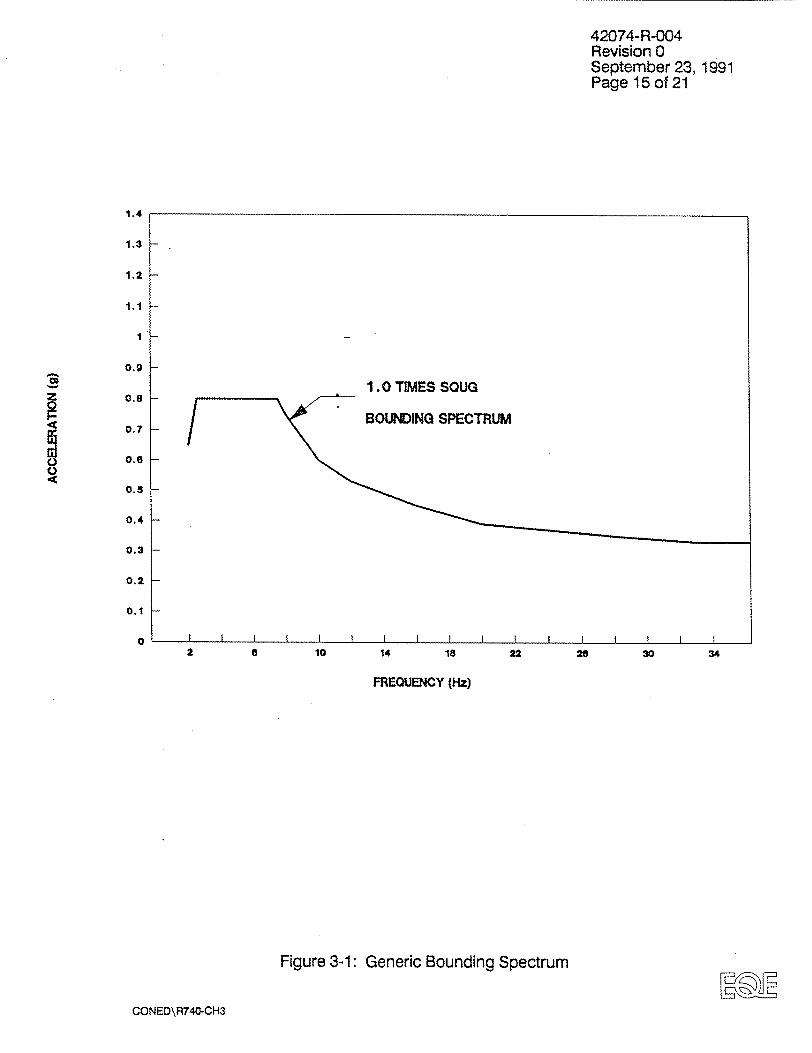
3-1 SSRAP Generic Bounding Spectrum ....................................... 15
4-1 Comparison of Indian Point Unit 2 ground spectrum with
the Generic Bounding Spectrum .............................................. 18
CONED/R740-TOC

42074-R-004 Revision 0 September 23, 1991 Page 8 of 21
1. INTRODUCTION AND BACKGROUND
1.1 Introduction
This report documents the seismic evaluation of Battery Charger 21 installed on
Elevation 33'-0" of the Control Building at the Indian Point Unit 2 Station. The
methods used for the evaluation are those developed for the Seismic Qualification
Utility Group (SQUG), based on a seismic experience data base of the perform
ance of similar components in past strong-motion earthquakes. These methods
have been developed for different generic equipment categories and are detailed
in the Senior Seismic Review and Advisory Panel (SSRAP) Report (Reference 2)
and EQE's Twenty Classes of Equipment Report (Reference 3). The use of
seismic experience data has been endorsed by the United States Nuclear
Regulatory Commission (USNRC) as a reasonable and cost effective method to
verify the seismic adequacy of components in operating nuclear power plants
(Reference 1).
The SSRAP recommendations, as stated in Reference 2, are used as the tech
nical basis for the work performed on this project. SSRAP is an independent
review board consisting of a five-member panel of seismic experts whose
members were jointly selected by SQUG and the USNRC.
1.2 Background of Seismic Experience Methods
In 1982, the SQUG was formed to address USNRC Unresolved Safety Issue (USI)
A-46, "Seismic Qualification of Equipment in Operating Nuclear Power Plants."
The goal of the SQUG was to develop a reasonable and cost effective resolution
to this issue, which could be applied generically to all of its member utilities. The
generic resolution to USI A-46 is based primarily on the use of seismic experience
data, lessons learned from earthquakes. In 1988, the SQUG produced a Generic
Implementation Procedure (Reference 4) describing the procedure to be used for
resolving USI A-46 for its member utilities. The GIP was endorsed by the NRC in
1988 (Reference 5).
CONED/R740-CH1

42074-R-004 Revision 0 September 23, 1991 Page 9 of 21
Battery chargers and inverters are included in the USI A-46 program by the SQUG. The SQUG review procedures are founded primarily on a data base of experience of similar equipment which have been subjected to earthquakes comparable to or stronger than the design Safe Shutdown Earthquakes (SSE) for typical nuclear plants in the eastern United States. The review procedures
developed by the SQUG, with approval from the USNRC, focus on demonstrated sources of seismic vulnerability in power plant equipment. The SQUG program and its supporting experience data base are described in detail in References 2 and 3. Appendix A provides a brief summary of the seismic experience data
base.
The experience data base has demonstrated that battery chargers and inverters are not susceptible to damage in earthquakes comparable to the SSE for nuclear plants in the eastern United States (earthquakes with a peak ground acceleration less than about 0.30g). This conclusion is based upon the experience data base which is founded on studies of over 100 facilities located in the strong motion
areas of 18 earthquakes that have occurred in the United States and throughout the world since 1971. Of this inventory, there are no examples of seismicallyinduced damage to properly anchored battery chargers or inverters that resulted
in loss of function or structural integrity.
CONED/R740-CH1

42074-R-004 Revision 0 September 23, 1991 Page 10 of 21
2. SCOPE
The workscope for this project is the seismic verification of Battery Charger 21
installed on the floor at Elevation 33'-0" of the Control Building at the Indian Point
Unit 2 Station. The project consists of evaluations and inspections to verify the
seismic adequacy of the equipment. This includes an in-plant inspection, seismic
spectrum comparison, and calculations to verify anchorage adequacy.
The operability requirements for this battery charger is that it must remain
functional following a SSE and must remain structurally intact and in place during
and after a SSE.
All work performed under this scope is in accordance with the latest revision of
EQE's Quality Assurance Program Manual.
CONED/R740-CH2
42074-R-004 Revision 0 September 23, 1991 Page 11 of 21
3. METHODOLOGY
3.1 Seismic Qualification Utility Group (SQUG) Methodology
The methodology employed for the seismic verification of equipment in this report was developed as part of the SQUG program to address USI A-46. A Generic
Implementation Procedure has been developed (Reference 4) and endorsed by
the NRC (Reference 5). The development of this methodology is based on the
information included in References 1 through 6.
In summary, very few components of nuclear plant systems are unique to nuclear
facilities. Nuclear plant systems include battery chargers and inverters, water chillers, compressors, heat exchangers, piping and piping components (e.g.,
valves, strainers), control panels, ducts, and many other items that are common
components of conventional power plants and industrial facilities. The seismic
experience data base was developed to address the problem of equipment qualification in nuclear plants for equipment which was purchased and/or installed as
commercial grade. By reviewing the performance of facilities that contain equipment similar to that found in nuclear plants, conclusions can be drawn about the
performance of nuclear plant equipment during and after a safe shutdown earth
quake. A pilot program to demonstrate the feasibility of using earthquake
experience in lieu of formal seismic qualification of equipment was performed in 1982 (Reference 6). This program demonstrated that selected types of equip
ment in data base facilities are similar to equipment in operating nuclear plants. It
further demonstrated that explicit seismic qualification of those equipment types
should not be required in view of their performance in strong earthquakes. The
last conclusion is currently supported by the program data base for nuclear sites
with ground PGA less than about 0.30g.
During the evaluation and walkdown, four areas should be considered. These
areas are:
", Equipment seismic capacity vs. seismic demand (see Section 3.2)
", Applicability of seismic experience data to plant specific equipment (see Section 3.3)
CONED\R740-CH3

42074-R-004 Revision 0 September 23, 1991 Page 12 of 21
"Equipment anchorage (see Section 3.3.1)
"* Seismic interaction (see Section 3.3.3)
3.2 Spectrum Comparison
A Generic Bounding Spectrum (Figure 3-1) was developed to compare the potential seismic exposure of equipment in a nuclear power plant with the estimated ground motion that similar equipment experienced (resisted) in earthquakes described in the data base.
"The comparison of the seismic bound with design horizontal ground response spectrum is judged to be acceptable for equipment mounted less than about 40 feet above grade (top of the ground surrounding the building) and for reasonably stiff structures. For equipment mounted more than about 40 feet above grade, comparison of 1.5 times the Bounding Spectrum with horizontal in-structure
spectra is necessary" (Reference 2).
3.3. Walkdown
A walkdown inspection of the battery charger was performed on September 4, 1991. This walkdown was in accordance with the SQUG GIP (Reference 4).
The EQE walkdown addressed the following issues:
,, Determination of whether equipment lies within the limitations of the caveats and similarity exclusion rules defined in the documentation (References 2, 3 and 4).
,, Judgmental evaluation of any factor that might affect the seismic performance of the equipment.
,, Flagging of any unusual or nontypical conditions, such as major modifications to standard equipment or equipment that is unique, for special review.
• , Assessment of the adequacy of equipment anchorage.
,, Assessment of seismic spatial systems interactions.
* Documentation of the walkdown.
CONED\R740-CH3
42074-R-004 Revision 0 September 23, 1991 Page 13 of 21
"The exercise of considerable judgment and experience is necessary during a seismic walkdown" (Reference 2). In accordance with the SQUG methodology, knowledgeable and practical individuals were selected to participate in the
walkdown as part of the Seismic Review Team (SRT). All engineers shall have knowledge of the failure modes and performance of components during strongmotion earthquakes in heavy industrial process plants and fossil fuel power plants and have knowledge of nuclear design standards and seismic design practices for nuclear power plants. Therefore, these engineers will have the ability and experience to perform seismic capability evaluations, including structural/ mechanical analysis, as needed.
The detailed evaluation methodology used by EQE and Con Edison during the walkdown is described in the Generic Implementation Procedure (Reference 4). The walkdown results were documented on Screening and Evaluation Work
Sheets (Attachment D).
3.3.1 Unit Anchorage. The presence of properly engineered anchorage is perhaps the most important single item which affects the seismic performance of equipment. Earthquakes have repeatedly demonstrated that equipment will slide, overturn, or move excessively when it lacks positive anchorage or when it does not have proper engineered anchorage. Anchored equipment failures in the earthquake experience data base include expansion bolts with very short embedments, friction clips (steel plates anchored to the concrete base which extend over the flange or base of the equipment without a positive connection), and base anchorage details with significant eccentricities which allow the equipment base to bend or tear or which generate large prying forces. Adequate anchorage is determined to be that which provides both adequate strength and stiffness. Adequate strength and stiffness of equipment anchorage can be determined by any one of many commonly accepted analysis methods.
3.3.2 Relay Review. Relays within the unit should be evaluated to determine possible effects of seismically induced vibration in accordance with the guidelines given in Reference 2, Section 5.
CONED\R740-CH3

42074-R-004 Revision 0 September 23, 1991 Page 14 of 21
3.3.3 Seismic Spatial Systems Interaction. In accordance with the SQUG methodology, an assessment of potential seismic spatial system interaction hazards shall be performed. The scope of this assessment is limited to an interaction review in the area surrounding the battery charger. The seismic interaction assessment considers examples of poor housekeeping, inadequately supported HVAC ducts, cable trays, conduit, piping, and instrument tubing. The SRT will also review the area for possible hazardous interactions with building structural members (e.g., columns, beams, bracing) or with architectural items (e.g., fire separation walls, stairways). This review will be performed to verify that impacts during a seismic event which rn-ight cause damage are precluded. The specific methodology to be used by EQE and Con Edison for performing the seismic spatial systems interaction review (including details on the basis for engineering judgment of the items reviewed) is presented in Section 4.5 of the GIP (Refer
ence 4).
3.3.4 Internal Component Composition. The battery charger or static inverter should be a solid-state type. The solid-state electrical construction is the primary type included in the earthquake experience database. The concern is that electronics which are not of the solid state variety (glass tubes, etc.) are vulnerable to earthquake damage.
3.3.5 Transformer Location. For the floor-mounted units, the transformer, which is the heaviest component of this equipment, should be positively anchored and mounted near the base of the cabinet. If not mounted near the base, then the load path should be evaluated.
3.3.6 Base Assembly Stiffness. The base assembly of floor-mounted units shall be properly braced or stiffened such that lateral forces in any direction do not rely on weak-way bending of sheet metal or thin webs of structural steel shapes. If such unbraced or stiffened steel webs exist in the nuclear plant, they shall be investigated and justified by the walkdown engineer by other means for adequacy of strength and stiffness.
3.4 Outlier Evaluation
Items that cannot be qualified by use of the SQUG methods as described above are considered "outliers". Outliers can be seismically verified either by further review of the seismic experience data base or by standard analysis techniques.
CONED\R740-CH3
2 6 10 14 18 22 26 30 34
FREQUENCY (Hz)
Figure 3-1: Generic Bounding Spectrum
CONED\R7T40-CH3
42074-R-004 Revision 0 September 23, 1991 Page 15 of 21
1.4
1.3
1.2
1.1
1
0.9
0.8
0.7S 0
0 0.6
0.5
0.4
0.3
0.2
0.1
0
M

42074-R-004 Revision 0 September 23, 1991 Page 16 of 21
4. RESULTS
This section presents the results of the seismic evaluation of Battery Charger 21 using the SQUG methodology summarized in Section 3.
4.1 Spectrum Comparison
The equipment location is on the floor at Elevation 33'-0" of the Control Building. This elevation is less than about 40 feet above grade (grade is Elevation 18'). Consequently, the IP2 site horizontal SSE free-field response spectrum was compared with the Generic Bounding Spectrum from Reference 2 in EQE calculation 41008.01-C-003 (Reference 9). This calculation shows the Generic Bounding Spectrum envelopes the IP2:SSE spectrum over the entire frequency range (Figure 4-1). This verifies the use of experience data for the seismic qualification of the battery charger.
4.2 Walkdown
Two different walkdowns of the battery charger were performed. One was by Con Edison and EQE personnel during which access to the internals of Battery Charger 21 was not possible. A walkdown of a similar unit which was accessible on the turbine floor deck was performed. This walkdown evaluated all SQUG GIP caveats except anchorage. The anchorage of Battery Charger 21 was walked down and evaluated at an earlier date by Con Edison personnel.
A number of key areas were addressed by the Seismic Review Teams including the caveats for battery chargers as outlined in Section 11 of Reference 2. These included unit anchorage, relays, seismic spatial systems interaction, internal construction, transformer location, and base assembly stiffness.
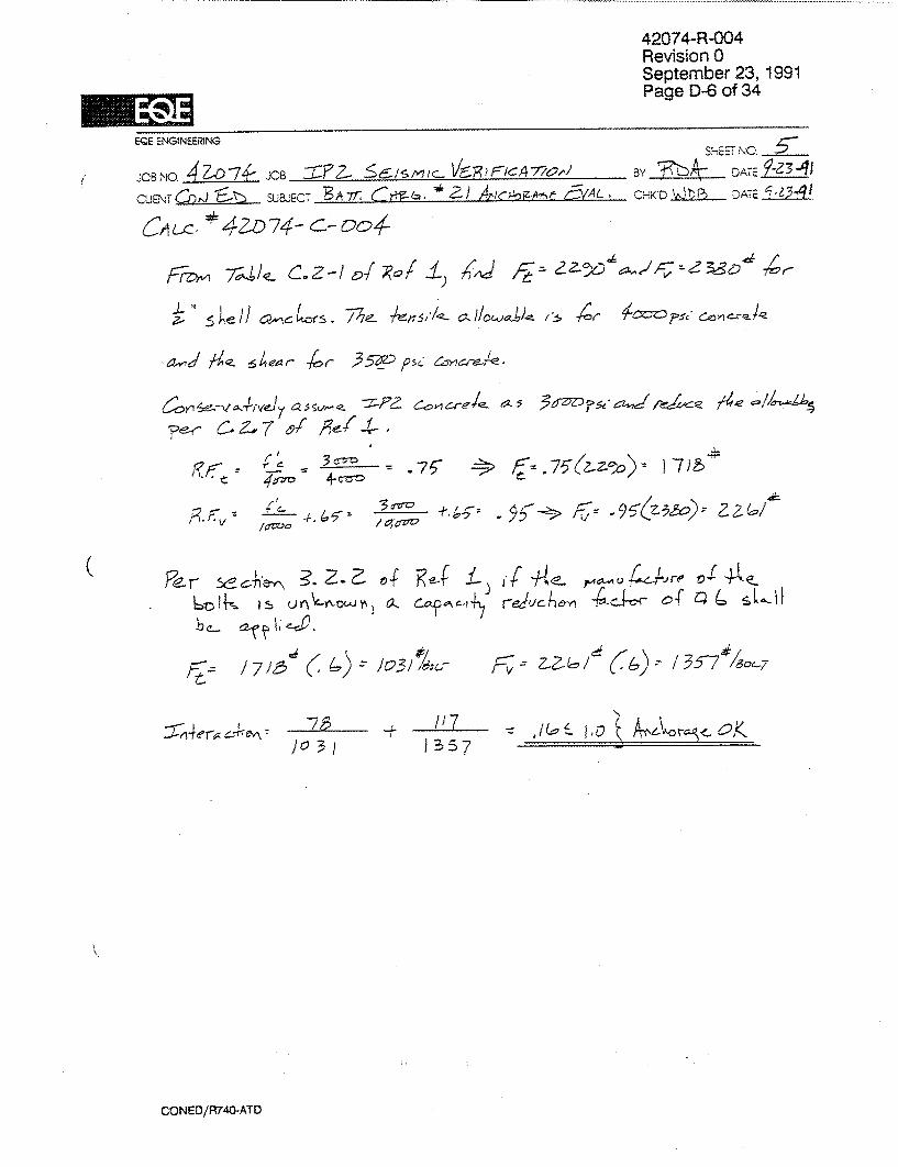
4.2.1 Unit Anchorage. The battery charger is secured to the floor by (4) 1/2" diameter shell anchors. This anchorage was evaluated by EQE in Reference No. 10 and was found to be adequate for the IP2 SSE event. This finding is contingent upon the anchor bolts being successfully tightness tested during the
future A-46 walkdowns.
CONED/R740-CH4

42074-R-004 Revision 0 September 23, 1991 Page 17 of 21
4.2.2 Relay Review.
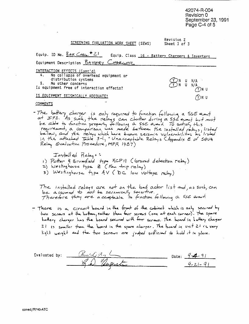
The Battery Charger is only required to function following a SSE event at IP2. As
such, the relays can chatter during a SSE event but must be able to function properly following the earthquake. To satisfy this requirement, a comparison was made between the installed relays and those which have been found to be so
seismically sensitive that they could be damaged during an earthquake. This
comparison is shown in Appendix C.
It was found that the IP2 relays are not on the seismic "bad actors" list and as
such are adequate to function following a seismic event at IP2.
4.2.3 Seismic Spatial Systems Interaction. The interaction review was performed
during the EQE walkdown and was in accordance with the guidelines of Reference 4. The walkdown investigated the area in the vicinity of the Battery Charger
and did not find any possibility of unacceptable interactions.
4.2.4 Internal Component Composition. The internals of the battery chargers were reviewed during the walkdown and found to be composed entirely of solid
state devices.
4.2.5 Transformer Location. The transformer was found to be mounted on a
metal shelf 3'-2" above the battery charger base. The transformer is secured to
the 1/8" thick shelf with (4) 1/4" A307 bolts. This shelf is in turn bolted to the
battery charger internal framing by (8) 1/4" bolts.
This mounting and associated load path was reviewed by the Seismic Review Team and was judged to be adequate to ensure position retention of the
transformer during and following an SSE event.
4.2.6 Base Assembly Stiffness. The base was found to be comprised of small, welded steel channels. These were judged to be adequate to transfer the seismic loads of the battery charger to the anchor bolts.
4.3 Outlier Evaluation
No outliers were identified during the walkdowns.
CONED/R740-CH4

42074-R-004 Revision 0 September 23, 1991 Page 18 of 21
6 10 14 18 22 26 30 34
FREQUENCY (Hz)
Figure 4-1: Comparison of the Indian Point Unit 2 Free Field SSE response spectrum with the Generic Bounding Spectrum.
CONED/R740-CH4
1.4
1.3
1.2
1
I 0
0
0.9
0.8
0.7
0.6
0.5
0.4
0.3
0.2
0.1
0
5% DAMPING]
1.0 TIMES SOUG BOUNDING SPECTRUM
IP2 SSE GROUND RESPONSE SPECTRUM
I I I I
2
K'ý ý EE

42074-R-004 Revision 0 September 23, 1991 Page 19 of 21
5. CONCLUSIONS
Battery Charger 21 installed on Elev. 33'-0" of the Control Building at Indian Point Unit 2 has been evaluated using the seismic experience data in accordance with References 2, 3 and 4. The conclusion of this evaluation is that the battery charger is seismically rugged and will remain functional following a SSE event at IP2.
This evaluation did not include an anchor bolt tightness check which must be performed during the future A-46 walkdowns.
CONED/R740-CH5

42074-R-004 Revision 0 September 23, 1991 Page 20 of 21
6. REFERENCES
1. USNRC. February 1987. NUREG 1211. Status Report, Unresolved Safety
Issue A-46. "Seismic Qualification of Equipment in Operating Plants."
2. Senior Seismic Review and Advisory Panel. February 28, 1991. "Use of
Seismic Experience and Test Data to Show Ruggedness of Equipment in
Nuclear Power Plants." Prepared for the Seismic Qualification Utility Group.
3. EQE Engineering. February 1989. "Summary of the Seismic Adequacy of
Twenty Classes of Equipment Required for the Safe Shutdown of Nuclear Plants." Draft. Prepared for the Seismic Qualification Utility Group.
4. Bishop, Cook, Purcell and Reynolds; EQE Incorporated; MPR Associates,
Inc.; Stevensons and Associates; and URS/John A. Blume and Associates,
Engineers. September 21, 1990. "Generic Implementation Procedure (GIP)
for Seismic Verification of Nuclear Plant Equipment." Revision 2. Prepared for the Seismic Qualification Utility Group.
5. USNRC. July 29, 1988. Generic Safety Evaluation Report on SQUG Generic
Implementation Procedure.
6. EQE Engineering. 1982. "Pilot Program Report, Program for the Development
of an Alternative Approach to Seismic Equipment Qualification." Prepared for the Seismic Qualification Utility Group.
7. EQE Incorporated. August 11, 1986. Revision 1. "Quality Assurance
Manual."
8. URS Corporation/John A. Blume & Associates, Engineers, "Seismic Verifica
tion of Nuclear Plant Equipment Anchorage, Volume 2: Anchorage Inspection
Workbook." May 1987.
9. EQE Engineering Calculation Number 41008.01 -C-003, "Spectrum Com
parison." Revision 0 dated December 29, 1988.
42074-R-004 Revision 0 September 23, 1991 Page 21 of 21
10. EQE Engineering Calculation Number 42074-C-004, "Battery Charger #21 Anchorage Evaluation." Revision 0 dated September 23, 1991.
11. Yanev, Peter I. and Sam W. Swan. September 1982. "Program for the
Development of an Alternative Approach to Seismic Equipment Qualification",
2 volumes. San Francisco, CA. EQE Incorporated.
42074-R-004 Revision 0 September 23, 1991 Page A-1 of 13
APPENDIX A
SUMMARY OF SEISMIC EXPERIENCE DATA BASE
CONED/R740-ATA

42074-R-004 Revision 0 September 23, 1991 Page A-2 of 13
SUMMARY OF THE EARTHQUAKE EXPERIENCE DATA BASE
Strong-motion earthquakes frequently occur in California and Latin American countries, where power plants or industrial facilities are included in the affected areas. By studying the performance of these earthquake-affected (or data base) facilities, a large inventory of various types of equipment installations can be compiled that have experienced substantial seismic motion.
The primary purposes of the seismic experience data base are summarized as follows:
"* To determine the most Common sources of seismic damage, or adverse effects, on equipment installations typical of industrial facilities.
"* To determine the thresholds of seismic motion corresponding to various types of seismic damage.
", To determine the performance of equipment during earthquakes, regardless of the levels of seismic motion.
"* To determine minimum standards in equipment construction and installation, based on past experience, to assure the ability to withstand anticipated seismic loads.
To summarize, the primary assumption in compiling an experience data base is that the actual seismic hazard to industrial installations is best demonstrated by the performance of similar installations in past earthquakes.
FACILITIES SURVEYED IN COMPILING THE DATA BASE. The seismic experience data base is founded on studies of over 100 facilities located in the strong motion areas of 18 earthquakes that have occurred in California and Latin America since 1971. The earthquakes and facilities included in the data base are summarized in Table 1.
The data base was compiled through surveys of the following types of facilities:
", Fossil-fueled power plants
", Hydroelectric power plants
"* Electrical distribution substations
"a Oil processing and refining facilities
"* Water treatment and pumping stations
", Natural gas processing and pumping stations
"* Manufacturing facilities
"* Large commercial facilities (focusing on their HVAC plants)
CONED/R740-ATA
42074-R-004 Revision 0 September 23, 1991 Page A-4 of 13
Standard procedures used in surveying data base facilities focus on collecting all information on damage or adverse effects of any kind caused by the earthquake. For a large majority of the facilities surveyed in the data base, this is not a lengthy task. Except for sites that experienced very high seismic motion (in excess of 0.50g peak ground acceleration), seismic damage to well-engineered facilities is normally limited to only a few items.
CONED/R740-ATA
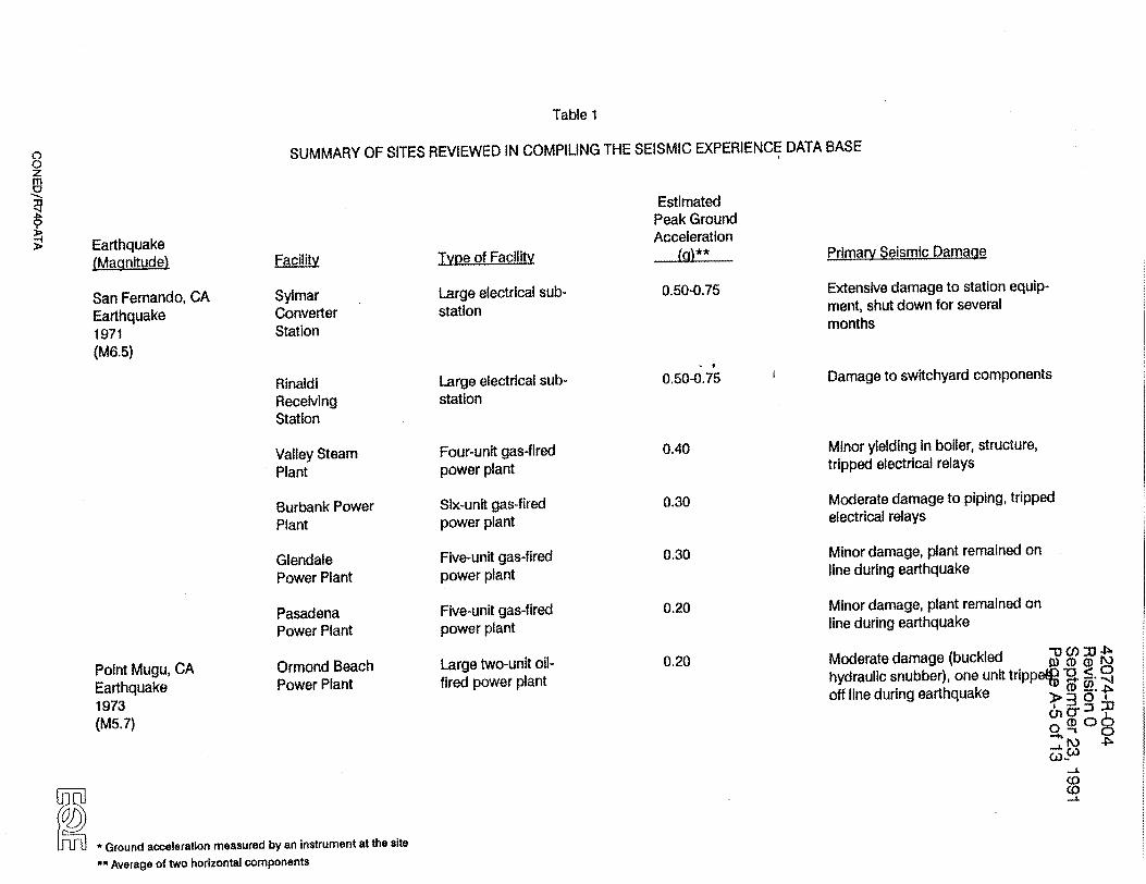
Table 1
SUMMARY OF SITES REVIEWED IN COMPILING THE SEISMIC EXPERIENCE DATA BASEC) 0 Z m
Earthquake (Magnitude)
San Fernando, CA Earthquake 1971 (M6.5)
Point Mugu, CA Earthquake 1973 (M5.7)
Facility
Sylmar Converter Station
Rinaldi Receiving Station
Valley Steam Plant
Burbank Power Plant
Glendale Power Plant
Pasadena Power Plant
Ormond Beach Power Plant
Type of Facility
Large electrical sub
station
Large electrical substation
Four-unit gas-fired power plant
Six-unit gas-fired power plant
Five-unit gas-fired power plant
Five-unit gas-fired power plant
Large two-unit oilfired power plant
Estimated Peak Ground Acceleration
(a00)**
0.50-0.75
0.50-0.;5
0.40
0.30
0.30
0.20
0.20
Primary Seismic Damage
Extensive damage to station equipment, shut down for several months
Damage to switchyard components
Minor yielding in boiler, structure, tripped electrical relays
Moderate damage to piping, tripped electrical relays
Minor damage, plant remained on line during earthquake
Minor damage, plant remained on line during earthquake
Moderate damage (buckled hydraulic snubber), one unit trilppn. ,. . 0 off line during earthquake D0
CD 0o
S * Ground acceleration measured by an instrument at the site
** Average of two horizontal components

Earthquake (Magnitude)
Ferndale, CA Earthquake 1975 (M5.5)
Santa Barbara, CA Earthquake 1978 (M5.7)
Imperial Valley, CA Earthquake 1979 (M6.6)
Humboldt, CA Earthquake 1980 (M7.0)
Coalinga, CA Earthquake 1983 (M6.7)
Estimated Peak Ground Acceleration
(Cl)**- -Facility
Humboldt Bay Power Plant
Goleta Substation
El Centro Steam Plant
Drop IV Hydro. Plant
Humbolt Bay Power Plant
Main Oil Pumping Plant
Union Oil Butane Plant
Shell Water Treatment Plant
S* Ground acceleration measured by an instrument at the site
** Average of two horizontal components
Type of Facility
Two gas-fired units, one nuclear unit
Electrical substation
Four-unit gas-fired power plant
Two-unit hydroelectric plant
Two gas-fired units one nuclear unit
Pumping station feeding oil pipe-line from Coalinga area
Petrochemical facility to extract butane and propane from well waste gas
Petrochemical facility to demimeralize water prior to steam injection Into oil wells
0.30*
0.26*
0.42*
0.30
0.25
0.60
0.60
0.60
Primary Seismic Damage
Damage to air preheater seismic stops, units tripped off line during earthquake
No damage, station remained on-line during earthquake
Moderate damage to piping and equipment, two units tripped off line during earthquake
Minor damage, plant remained online during earthquake
Moderate damage to piping, two units tripped off-line during earthquake
Extensive damage to equipment anchorages, plant shut down during earthquake
Moderate damage to structures and tanks, plant shut down during W Mo 33 *0< 0
earthquake (0'0
Moderate damage to equipment O 0
anchorage, plant shut down _during earthquake
(0

Estimated Peak Ground Acceleration
(.. a)** -Type of Facility Primary Seismic Damage
Morgan Hill, CA Earthquake 1984 (M6.2)
Coalinga Water Treatment
Coalinga Substation No. 2
Shell tank Farm No. 29
Pleasant Valley
f
San Luis Canal Pumping Stations (29)
Gates Substation
Kettleman Compressor Station
United Tech. Chemical Plant
IBM/Santa Teresa Facility
Potable water purification facility
Electrical Substation
Oil storage tank farm
Pumping station to supply Pumping Plant water from the San Luis Canal to the Coalinga Canal
Agricultural pumping stations taking water from the San Luis Canal
Large electrical substation
Natural gas pipeline booster station
Large research facility for missile systems development
Large computer facility for software development
0.60
0.60
0.60
0.56'"
0.20-0.60
0.25
0.20
0.50
0.37*
Minor damage to equipment anchorage, plant shut down during earthquake
Extensive structural damage to control house, station remained operable during earthquake
Extensive damage to 60% of tanks associated equipment not damaged
Minor damage, plant shut down during earthquake
Minor damage, power temporarily lost during earthquake
Minor damage
Minor damage, plant operated through earthquake
Moderate damage to cable trays an4(D M p, ducts, power lost during earthquakqe -, <
.. n 0 Minor damage, facility operated -ro
through earthquake W
CD• Co3
Ir••I * Ground acceleration measured by an Instrument at the site
** Average of two horizontal components
Earthquake (Magnitude) Facilit

Estimated Peak Ground Acceleration
(g)•**--Facilit
San Martin Winery
Witron Electronics Plant
Metcalf Substation
Evergreen Community College
Mirassou Winery
Bata Shoe Factory
San Isidro Substation
Uolieo Water Pumping Plant
Terquim Tank Farm
Vicuna Hospital
Ground acceleration measured by an instrument at the site
** Average of two horizontal components
Type of Facility
Winery
Electronics manufacturing facility
Large electrical substation
Large college complex with self-contained HVAC power plant
Winery
Four-building factory and tannery
Electrical substation
Water pumping station
Oil/acetate/acid storage tank farm
Four-story hospital
0.35
0.35
0.40
0.20
0.20
0.64
0.58*
0.55
0.55
0.55
Primary Seismic Damage
Extensive tank damage
Moderate damage to equipment anchorage and ducts, facility not in operation at time of earthquake
Moderate switchyard damage, power lost during earthquake
Minor damage to architectural features
Moderate tank damage
Extensive structural and equipment damage power lost during
Moderate switchyard and equipment damage, power lost during earthquake
Moderate piping and equipment damage, power lost during earthquake
0(DV M
Extensive tank damage D _..p,
>30 O0 n
Moderate damage to piping and r P. equipment anchorage hospital CAP
closed following earthquake -L
Earthquake NMagnitudej
Chile Earthquake 1985 earthquake (M7.8)

Facility
Rapel Hydroelectric Plant
San Sebastian Substation
Concon Petroleum Refinery
Oxiquim Chemical Plant
Concon Water Pumping Station
Type of Facility
Five-unit hydroelectric plant
Electrical substation
Petrochemical facility producing fuel oil, asphalt, gasoline, and other petroleum products
Chemical facility producing various chemicals, including feed stock for paint ingredients
Water pumping station
Estimated Peak Ground Acceleration
(g)I±
0,40*
0.35
0.30
0.30
0.30
Primary Seismic Damaae
Moderate damage to equipment, relays, and switchyard equipment, plant not on-line during earthquake
No damage
Moderate equipment and tank damage, relay actuation tripped plant off line
Moderate damage to tanks and piping, power lost during earthquake
Moderate damage to piping and equipment anchorages, power lost during earthquake
Renca Power Plant
Laguna Verde Power Plant
Las Ventanas Copper Refinery
Las Ventanas Power Plant
Ground acceleration measured by an instrument at the site
** Averaoe of two horizontal components
Two-unit coal-fired peaking power plant
Two-unit coal-fired peaking plant
Copper refinery/foundry/ power plant
Two-unit gas-fired power plant
0.30
0.25
0.25
0.25*
Minor damage to structure and equipment anchorage plant not on-line during earthquake
Moderate damage to structural and piping, plant not online during earthquake W (D D
n-'O < 0J Extensive structural damage, plant > 3
taken off-line during earthquake b rr = ,- D C)
0. 0
Moderate damage to structure and c equipment, one line tripped unit
off-during earthquake
Earthquake (Maanitude)

Type of Facility
Estimated Peak Ground Acceleration
(cl)*_*... Primary Seismic Damage
San Cristobal Substation
Las Condes Hospital
Mexico Earthquake 1985 (M8.1)
InflernIllo Dam
La Villita Power Plant
SICARTSA Steel Mill
Fertimex Fertilizer Plant
Adak, Alaska Earthquake 1986 (M7.5)
North Palm Springs, CA Earthquake 1986 (M6.0)
Adak Naval Base
Devers Substation
Whitewater Hydro. Plant
Electrical substation
Four-story hospital
Six-unit hydroelectric plant
Four-unit hydroelectric
plant
Large, modern steel mill
Fertilizer plant
Diesel-electric power plants, electrical substations, sewage lift stations, water treatment plant, steam plants
Large electrical distribution substation
Small hydroelectric power plant
0.25
0.20
0.15
0.14
0.25-0.50
0.25-0.50
0.25
0.85*
0.50
Moderate structural and switchyard damage, power was lost during earthquake
Minor damage, hospital operated through earthquake
No damage
No damage
Extensive damage to equipment and structures, facility shut down following earthquake
Extensive damage to equipment and structures, facility shut down following earthquake
Minor structural and equipment damage, facilities remained online during earthquake
Extensive switchyard damage, plant lost power during earthquake
Minor equipment damage
"1D0 M " bi, 0 < 0
>E30' ,_
Q)(D 06 ~'0
C.o (0 CA)
* Ground acceleration measured by an Instrument at the site
Earthquake (Magnitude) Faculty

0 0 Z m
Earthquake (Magnitudel
Chalfant Valley, CA Earthquake 1986 (M6.0)
controller,
San Salvador Earthquake 1986 (M5.4)
Cerro Prieto, Mexico Earthquake 1987 (M5.4)
Bay of Plenty, New Zealand 1987 (M6.25)
Caxton Paper Mill
Kawerau Substation
Whakatane Board Mill
* Ground acceleration measured by an instrument at the site
' Average of two horizontal components
Facilly
Control Gorge Hydro Plant
Hi-Head Hydro
Plant
Soyapango Substation
San Antonio substation
Power Plant 1
Power Plant 3
Edgecumbe Substation
New Zealand Distillery
Estimated Peak Ground Acceleration
0.25
0.25
Type of Facility
Two-unit hydroelectric plant
Small one-unit unmanned
hydroelectric plant
Electric substation
Electrical substation
Geothermal power plant
Geothermal power plant
230/115 kV substation
Liquor distillery
Paper and pulp mill
230/115 kV substation
Paper mill producing cardboard
Primary Seismic Damage
Minor switchyard damage, plant lost power during earthquake
Damage to programmable
plant lost power during earthquake
Moderate switchyard and equipment damage tripped electrical relays
Minor switchyard damage, plant lost
power during earthquake
No damage, both plants tripped by actuation of sudden pressure relays
Extensive switchyard damage, plant lost power during earthquake
Extensive tank damage, plant lost power during earthquake
0.50
0.40
0.20-0.30
0.20-0.30
0.50-1.0
0.50-1.0
0.40-0.55
0.40-0.55
0.30
Moderate equipment and duct damage plant lost power during -0 C/ X earthquake .) CD (
Extensive switchyard damage, plant> 3 o_-" lost power during earthquake "• : M
Moderate equipment damage, plant 'o.5 lost power during earthquake C.0
Co
Facility
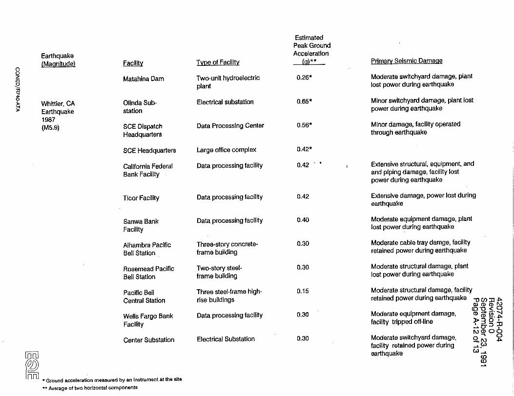
Matahina Dam
Olinda Substation
SCE Dispatch Headquarters
SCE Headquarters
California Federal Bank Facility
Ticor Facility
Sanwa Bank Facility
Alhambra Pacific Bell Station
Rosemead Pacific Bell Station
Pacific Bell Central Station
Wells Fargo Bank Facility
Center Substation
Earthquake (MaanitudeI
Estimated Peak Ground Acceleration
(g)**
0.26*
0.65*
0.56*
Primary Selsmic Damage
Moderate switchyard damage, plant
lost power during earthquake
Minor switchyard damage, plant lost power during earthquake
Minor damage, facility operated through earthquake
0 0 z m
Type of Facility
Two-unIt hydroelectric plant
Electrical substation
Data Processing Center
Large office complex
Data processing facility
Data processing facility
Data processing facility
Three-story concreteframe building
Two-story steelframe building
Three steel-frame highrise buildings
Data processing facility
Electrical Substation
0.15
0.30
0.30
Extensive structural, equipment, and and piping damage, facility lost power during earthquake
Extensive damage, power lost during earthquake
Moderate equipment damage, plant lost power during earthquake
Moderate cable tray damge, facility retained power during earthquake
Moderate structural damage, plant lost power during earthquake
Moderate structural damage, facility retained power during earthquake .V CO ,,
Q3 D CD < Moderate equipment damage, CD ̀ _.. facility tripped off-line > 0
K)CD 06 Moderate switchyard damage, o 41'
-'hC facility retained power during " 2 earthquake C "
CD .,D=
* Ground acceleration measured by an instrument at the site
** Average of two horizontal components
0.42*
0.42
0.42
0.40
0.30
0.30
Whittier, CA Earthquake 1987 (M5.9)
Type of Facility
Estimated Peak Ground Acceleration
(g)** Primary Seismic Damage
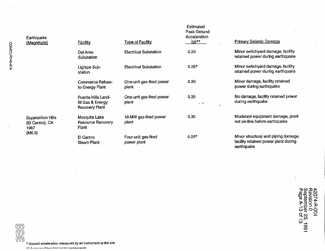
Superstition Hills (El Centro), CA 1987 (M6.3)
Del Amo Substation
Lightpe Substation
Commerce Refuseto-Energy Plant
Puente Hills Landfill Gas & Energy Recovery Plant
Mesquite Lake Resource Recovery Plant
El Centro Steam Plant
Electrical Substation
Electrical Substation
One-unit gas-fired power plant
One-unit gas-fired power plant
16 MW gas-fired power plant
Four-unit gas-fired power plant
0.20
0.26*
0.30
0.20
Minor switchyard damage, facility retained power during earthquake
Minor switchyard damage, facility retained power during earthquake
Minor damage, facility retained power during earthquake
No damage, facility retained power during earthquake
Moderate equipment damage, plant not on-line before earthquake
Minor structural and piping damage, facility retained power plant during earthquake
0.30
0.25*
* Ground acceleration measured by an Instrument at the site
** -- ,nf tx,-, ý rmnonenfiý
Earthquake (Magnitude) Facility
D -0 < 0
->3 0
W00 (0
C) r " 'p_L CO• C'a I,
42074-R-004 Revision 0 September 23, 1991 Page B-1 of 26
APPENDIX B
GENERIC EQUIPMENT CLASS
OF BATTERY CHARGERS
coned/R740-ATB

42074-R-004 Revision 0 September 23, 1991 Page B-2 of 26
SECTION 16
BATTERY CHARGERS AND INVERTERS
SUMMARY OF SEISMIC ADEQUACY
This class of equipment includes solid-state battery chargers and
inverters. Battery chargers and inverters perform similar functions,
contain similar components, and are packaged-in similar cabinets. IEEE
Standard 650-1979 groups these two components together for Class 1E
qualification purposes due to their inherent similarity. Although
inverters and battery chargers-perform electrically inverse functions,
they are physically very similar and will be treated in the same class.
16.1 DEFINITION OF EQUIPMENT-CLASS
Battery chargers are assemblies of electronic components whose function
is to convert ac input into dc output. Inverters are assemblies of
similar electronic components whose function is to convert dc input into
ac output. Battery chargers and inverters are normally housed in floor
or wall-mounted cabinets.
Battery Chargers
The primary electrical function of a battery charger (i.e., production
of direct current by means of an alternating voltage) is accomplished
using a rectifier. Traditionally, many kinds of rectifiers have been
used for battery charging, including rotary converters, mercury-arc
rectifiers, and thermionic valves. Most modern battery chargers are
based on solid-state rectifiers consisting of semiconductors of
selenium, germanium, or silicon diodes. Solid-state battery chargers
have substantial representation in the data base and are the focus of
this equipment class. Rotary type chargers and inverters are
represented in the equipment class of Motor Generators.
The primary components of battery chargers include solid-state diodes,
transformer coils, capacitors, electronic filters, and resistors. In
addition, the primary components are usually protected from electrical
896/20c04c16/3 16-1 1 -
coned/R740-ATB
42074-R-004 Revision 0 September 23, 1991 Page B-3 of 26
faults by molded case circuit breakers and fuses. The internal
components are normally bolted either to the rear panel or walls of the
cabinet, or to interior panels or steel frames mounted within the
cabinet. The front panel of the cabinet typically contains
instrumentation and controls, including ammeters, voltmeters, switches,
alarms, and control relays. Figure 16-1 shows the arrangement of
components within a typical wall-mounted battery charger.
Inverters
Inverters perform the Qpposite function of battery chargers; they change
dc into ac power. The primary components of an inverter are similar to
those of a battery charger except that inverters use a solid-state
thyristor (or silicon-controlled rectifier) instead of a diode, and have
a commutation control circuit which activates the thyristor in
converting dc voltage into positive and negative half-cycles. Virtually
all inverters used in power plant applications are designed using solid
state components. Figure 16-2 shows a typical arrangement of components
in an inverter.
Battery Charger and Inverter Characteristics
Battery chargers and inverters are typically mounted in separate
cabinets. For applications sized for the same power system, the overall
dimensions and weight of chargers and inverters are usually similar.
Some manufacturers supply the battery charger and inverter as an
assembly of two adjoining cabinets.
Battery chargers and inverters cover a range of sizes and capacities.
The smallest units are wall-mounted or rack-mounted with typical
dimensions of 10 to 20 inches in height, width, and depth, and typical
weights of 50 to 200 pounds. Typical wall-mounted and rack-mounted
units are shown in Figure 16-5 (lower photograph) and Figure 16-4 (lower
photograph), respectively. Most power plant applications require
larger, floor-mounted units, as shown in Figure 16-5 (upper photograph)
and Figure 16-7. Typical cabinet dimensions are 20 to 40 inches in
width and depth, and 60 to 80 inches in height. The weights of the
896/20c04c16/3 16-2
coned/R740-ATB

42074-R-004 Revision 0 September 23, 1991 Page B-4 of 26
floor-mounted chargers and inverters range from several hundred to
several thousand pounds, depending on the power requirements of the
system they serve.
Typical ac voltages to battery chargers and from inverters range from
120 to 480 volts. Voltages in dc power typically range from 24 to 240
volts.
Industry standards are maintained for the construction of cabinets by
Underwriter's Laboratory Standard (e.g., UL-1236 1984) and the National
Electrical Manufacturer's Association (e.g., NEMA Standard ICS-6 1978).
These standards determine the minimum structural framing and sheet metal
thickness for charger and inverter cabinetry as a function of size.
Equipment Anchorage
Floor-mounted cabinets typically rest on base channels. Holes are
normally provided in the bottom flange of the base channel for embedded
bolts or expansion anchors into the concrete floor. Alternately, the
cabinet may be welded to embedded steel, either by puddle welds through
the bolt holes or tack welds along the periphery of the base channels.
Wall- or rack-mounted units are normally anchored by bolts through the 'rear panel of the cabinet. If the unit is attached directly to a
concrete wall, expansion anchors are normally used. Rack-mounted units are typically anchored by threaded connections such as the
manufacturer's standard spring-supported nut into a Unistrut member.
Data Base Applications
The most common applications for both battery chargers and inverters are as components of an uninterruptible power supply (UPS). UPS systems are
used extensively to supply high quality power to equipment such as
programmable control systems or computers. A typical UPS consists of a
solid-state inverter, a battery charger, a set of lead-acid storage
batteries, and an automatic transfer switch. These components
effectively isolate critical loads from all types of power
896/20c04c16/3 16-3 r; 7ý-
coned/R740-ATB

42074-R-004 Revision 0 September 23, 1991 Page B-5 of 26
perturbations, including line transients, voltage fluctuations, and loss
of normal offsite power.
In the normal mode, a UPS battery charger is powered from an offsite ac
power line. It provides regulated dc output to the inverter, while
simultaneously float-charging the battery. This system acts as a buffer
to critical systems, isolating them from voltage transients and
frequency fluctuations. The inverter then supplies a steady flow of ac
power to critical loads. In the event of a loss of offsite power, the
critical load continues to be supplied by the UPS inverter, which
obtains power from the standby batteries. The UPS batteries will
continue to supply ac power through the inverter until the emergency
generators come on-line or commercial offsite ac power is restored.
Application in Nuclear Plants
In nuclear plants, chargers serve the station batteries which provide a
dc power source to controls, instrumentation and switchgear. A portion
of the dc power from the batteries is routed through inverters which
provide a source of ac power to critical equipment. Inverters and
battery chargers in nuclear plants are, in general, the same type, size,
and construction as those found in the data base, as illustrated in the
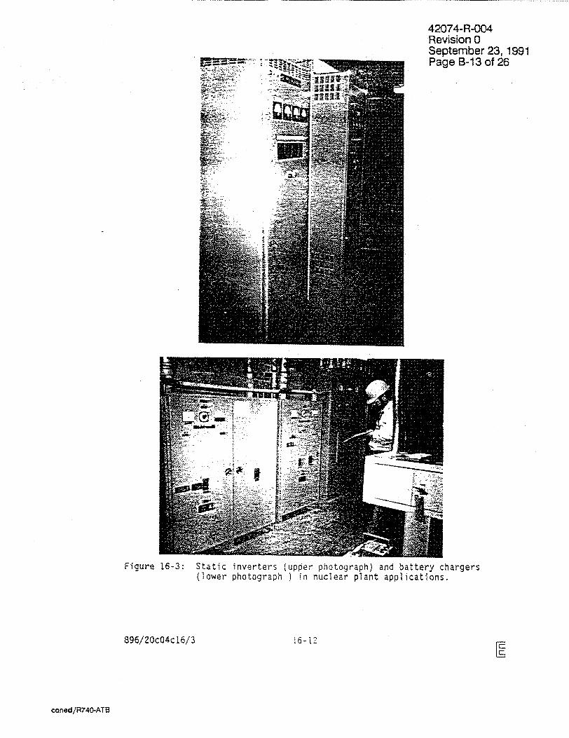
examples from nuclear plants shown in Figure 16-3.
16.2 DATA BASE REPRESENTATION FOR BATTERY CHARGERS AND INVERTERS
Figures 16-4 through 16-15 present examples of battery chargers and
inverters within the data base. The data base inventory of
inverters/chargers includes about 90 examples, representing 36 sites and
14 of the earthquakes studied in compiling the data base. Of this
inventory, there is one instance of seismically-induced loss of function
to an inverter.
Figure 16-16 presents a bar chart that illustrates the inventory of
battery chargers/inverters at various data base sites as a function of
their estimated PGA.
896/20c04c16/3 16-4
coned/R740-ATB

42074-R-004 Revision 0 September 23, 1991 Page B-6 of 26
The general bounds of the data base representation for the equipment class of battery chargers and inverters are summarized below.
Solid-state inverters and battery chargers are represented in freestanding, rack-mounted, and wall-mounted configurations. Floor or wall anchorage of cabinets includes bolts (typically 3/8- or 1/2-inch), welds, or friction clips.
Data base representation includes the following components:
"* The sheet metal enclosure and all internal components
"* Junction boxes attached to the cabinet
"* Attached cable or conduit between the unit and the nearest building anchor point
Basis for the Generic Bounding Spectrum
The Svlmar Converter Station is one of the major power facilities reviewed in the SQUG pilot program. The station, located near the fault rupture of the 1971 San Fernando Earthquake, is estimated to have experienced at least O.50g peak ground acceleration, with about ten seconds of strong motion.
The station control building is a three-story steel-frame structure. The basement of the station contains two battery chargers, which are bolted to steel angle frames (Figure 16-4, lower photograph). The chargers were manufactured by Powertronic Equipment Limited, of Ontario, Canada. The frame is bolted to the concrete floor with four 1-inch anchor bolts. The battery chargers were undamaged by the earthquake.
The Union Oil Butane Plant experienced a peak ground acceleration of approximately O.60g, with strong motion occurring for a duration of about 15 seconds, during the 1983 Coalinga Earthquake. This PGA is a conservative estimate, based on the nearest ground motion record of 0.56g (an average of the horizontal components) recorded at the Pleasant Valley Plant much further from the fault.
896/20c04c16/3 16-5
coned/R740-ATB

42074-R-004 Revision 0 September 23, 1991 Page B-7 of 26
The plant contains three small battery chargers wall-mounted into the
rear of sheet metal cabinets (Figure 16-5, lower photograph). They are
manufactured by Nife Corporation of Rhode Island and operate at 240
volts, 20 amps dc. All battery chargers were undamaged by the
earthquake.
The Main Oil Pumoino Plant is located near the epicenter of the initial
shock in the 1983 Coalinga sequence of earthquakes. The ground motion
spectrum recorded at the Pleasant Valley Plant is applicable to the
nearby Main Oil Pumping Plant site.
The plant contains one wall-mounted battery charger and a floor-mounted
inverter. The charger, manufactured by Power Conversion Products,
operates at 120 volts, 5 amps. The inverter was manufactured by Exide Power Systems, and operates at 105/140 volts dc input, 120 volts ac
output (Figure 16-5, upper photograph). The inverter was not anchored
during the earthquake and slid several inches. Both units were
undamaged by the earthquake.
The Pleasant Valley Pumping Plant recorded ground motion closest to the
epicenter of the 1983 Coalinga sequence of earthquakes. Strong motion
monitors are located in the station switchyard, as well as in the
basement, operating floor, and on the roof of the station building. The
monitor located in the switchyard (free-field) recorded an average
horizontal peak ground acceleration of 0.56g, with a duration of strong
motion of about 15 seconds.
The station includes two floor-mounted battery chargers. The chargers,
manufactured by Exide, are anchored with four 1/2-inch bolts in the corners of the cabinets. The units were undamaged by the earthquakes,
but there was evidence of impact with the adjacent wall.
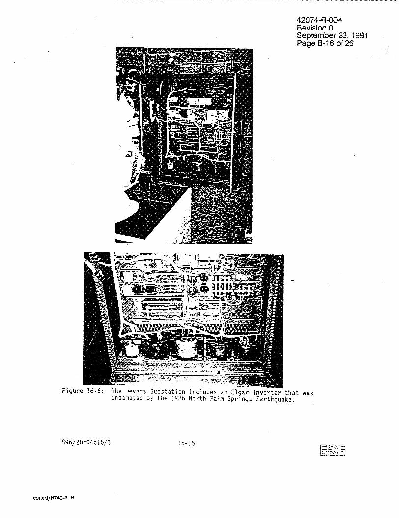
The Devers Substation recorded an average horizontal PGA of 0.85g with a
duration of about six seconds, during the 1986 North Palm Springs
Earthquake. The site experienced from two to five times more motion
than its design basis, resulting in extensive damage to switchyard
equipment.
896/20c04c16/3 16-6 fE..
coned/R740-ATB
42074-R-004 Revision 0 September 23, 1991 Page B-8 of 26
The substation control building is a one-story reinforced concrete-block
structure with a wood diaphragm roof. The station includes two battery
chargers and one inverter (Figure 16-6). The units were undamaged by
the earthquake and operated for two hours following the event.
Eventually, the batteries serving the inverter were exhausted and the
system switched off.
16.3 INSTANCES OF SEISMIC EFFECTS AND DAMAGE
The experience data base includes one instance of seismic damage to an
inverter that resulted in a loss of function and several instances of
seismic effects which did not dffect functionality.
At the Wells Fargo Data Processing Center, which experienced an
estimated PGA in excess of O.-3Og during the 1987 Whittier Earthquake,
one Uninterruptible Power Supply (UPS) unit sustained five blown fuses
following the earthquake (Figure 16-12). The blown fuses in the unit
caused a loss of emergency power to the facility.
The UPS is an Emerson "Acu-Power" which regulates incoming. ac power and
supplies emergency power to the facility. The system requires three
units in order to maintain full power. If less than three units are
available, overload breakers will actuate, and all UPS systems will
disconnect. At the time of the earthquake, one of the four UPS units
was down for maintenance; the remaining three units were operating to
supply ac power to the facility.
Approximately 4-1/2 hours following the earthquake, system problems in
the power grid caused a loss of offsite power. When power was lost to
the facility, one of the operating UPS units sustained five blown fuses.
The facility engineer and the manufacturer suggested threeý possible
explanations for the damage. When offsite power is lost, emergency dc
power is supplied by batteries. If one of the cells is not functional,
certain fuses within the UPS will blow in order to protect the more
valuable subcomponents. Another potential explanation is that power
surges occurred prior to the loss of offsite power, which could blow
896/20c04c16/3 16-7
coned/R740-ATB
42074-R-004 Revision 0 September 23, 1991 Page B-9 of 26
fuses in the unit. A third and equally plausible explanation is that the UPS unit contained faulty fuses or other subcomponents.
At the Del Amo Substation, which experienced an estimated PGA of O.20g during the 1987 Whittier Earthquake, a battery charger was tripped by the actuation of a molded case, branch circuit breaker in the associated distribution panel (Figure 16-13). The distribution panel is a 110/220 volt dead front switchboard, manufactured by Square 0. The distribution panel is anchored with 1/2-inch bolts in the corners of the cabinet, and the adjacent cabinets in the assembly are bolted together. There is about a 1/2-inch clearance between the panel and the adjacent wall. The breaker actuation appears to be the result of impact of the panel with the wall.
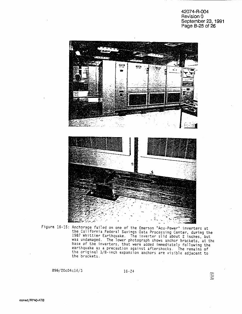
At the California Federal Bank Data Processing Facility, an Emerson "Acu-Power" Uninterruptible Power Supply (UPS) pulled or sheared all of its anchor bolts (Figure 16-15). The unit was anchored with 3/8-inch shell type expansion anchors. The UPS was not damaged, in spite of a PGA in excess of 0.40g measured nearby.
At the Sanwa Bank Computer Facility, which experienced an estimated PGA of 0.40g during the 1987 Whittier Earthquake, two UPS units sheared their anchorage and slid about 12 inches during the earthquake. The cabinets were observed to have poor anchorage-concrete pad edge distance. The units remained functional.
No additional instances of seismically-induced damage to inverters and battery chargers were found in an extensive literature search/telephone
survey.
16.4 SOURCES OF SEISMIC DAMAGE
The seismic experience data base indicates that static inverters and battery chargers possess characteristics which generally preclude damage in earthquakes. With the exception of units with poorly designed
anchorage, the experience data base demonstrates no tendency for seismic
damage to static inverters and battery chargers.
896/20c04c16/3 16-8 F%
coned/R740-ATB

42074-R-004 Revision 0 September 23, 1991 Page B-10 of 26
16.5 BIBLIOGRAPHY
1. "IEEE Standard for Qualification of Class 1E Static Battery
Chargers and Inverters for Nuclear Power Generating Stations."
n.d. IEEE Standard 650-1979.
2. Underwriters Laboratory Standard UL-1236. August 1978. "Electric
Battery Chargers." Northbrook, IL.
3. National Electrical Manufacturer's Association (NEMA) Standard
ICS-6. April 1980. "Enclosures for Industrial Controls and
Systems." Washington, DC
4. Ratelco Inc. June 1985. "Emergency AC Power: Count on It, with
Ratelco on Charge!" Power Systems Division.
5. Emerson Electric Co. April 1987. "AP300 Series 60 Hz
Uninterruptible Power System." Santa Ana, CA.
6. KW Control Systems, Inc. n.d. "Introduction to the Uniblock UPS
System." Middletown, NY.
7. Atlas Energy Systems. n.d. "The Atlas UPC/Unterruptible Power
Conditioner."
8. RTE DELTEC Corporation. 1985. "Uninterruptible Power Systems."
San Diego, CA.
9. Square D Company. November 1984. "DC to AC Sine Wave Inverters
Especially for Telecommunications Systems."
10. T. B. Wood's Sons Company. January 1986. "E-TRAC AC Inverter."
Chambersburg, PA.
11. Zenith Controls, Inc. n.d. "Zenith ZTS Transfer Switches."
Chicago, IL.
896/20c04c16/3 16-9
coned/R740-ATB

42074-R-004 Revision 0 September 23, 1991 Page B-11 of 26
Li1 CHOKE
I( zlý
TIMER OR
MANUAL FLOAT EQUALIZE
SWITCH
GROUND DETECTION
SWITCH
FLOAT __1 VOLTAGE-CONTROL T
POWER TRANSFORMERV EQUALIZE VOLTAGE CONTROL
Courtesy Gould Incorporated
Figure 16-1: Typical wall-mounted solid-state battery charger.
896/20c04c16/3 16-10
U_
ooned/R740-ATB
lab

42074-R-004 Revision 0 September 23, 1991 Page B-12 of 26
fronsfer-Z- erfer con-ro-sed-ion
Figure 16-2:
896/20c04c16/3
Typical inverter.
16-11
Input filter /ocotin
Ac output filter
powertion
coned/R740-AT8
42074-R-004 Revision 0 September 23, 1991 Page B-13 of 26
Figure 16-3: Static inverters (upper photograph) and battery chargers (lower photograph ) in nuclear plant applications.
896/20c04c16/3 16-i2
coned/R740-ATB

A wall-mounted PR Industries battery charger Station.
Figure 16-4: Battery chargers Earthquake.
896/20c04c16/3
42074-R-004 Revision 0 September 23, 1991 Page B-14 of 26
at the Rinaldi Receiving
At the Sylmar Converter Station, Powertronic battery chargers are bolted to a steel frame that is bolted into the concrete floor.
at sites affected by the 1971 San Fernando
16-13
coned/R740-AT8

42074-R-004 Revision 0 September 23, 1991 Page B-1 5 of 26
This Exide inverter at the Main Oil Pumping Plant was unanchored at the time of the earthquake. It slid several inches without damage.
This small wall-mounted battery charger is bolted to the rear of a sheet metal cabinet at the Union Oil Plant.
Figure 16-5:
896/20c04c16/3
Battery chargers and inverters at near-field sites affected by the Coalinga sequence of earthquakes of 1983.
16-14
coned/R740-ATB
42074-R-004 Revision 0 September 23, 1991 Page B-16 of 26
A) 4
... ..
Figure 16-6:
896/20c04c16/3
The Devers Substation includes an Elgar Inverter that was undamaged by the 1986 North Palm Springs Earthquake.
16-15
coned/R740-ATB

42074-R-004 Revision 0 September 23, 1991 P•,B-17 of 26
S,4r,
The Rapel Hydroelectric Plant has approximately five AEG battery chargers and five AEI inverters, each anchored with four 3/8-inch anchor bolts.
I
Las Ventanas Power Plant contains at least two inverters manufactured by Solid-state Controls, Inc., each anchored with four 3/8-inch anchor bolts.
Figure 16-7:
896/20c04c16/3
Battery chargers and Chile Earthquake.
inverters at sites affected by the 198E
16-16
coned/R740-ATB

42074-R-004 Revision 0 September 23, 1991
S926
The battery charger at the Burbank Power Plant is bolted to steel channels that are anchored to the concrete floor with 1/2inch (est.) bolts.
SCI Inverter located in the basement at the Glendale Power Plant.
Figure 16-8:
896/20c04c16/3
Battery chargers and inverters at sites affected by the 1971 San Fernando Earthquake.
16-17
coned/R74M-ATB
42074-R-004 Revision 0 September 23, 1991 Page B-19 of 26
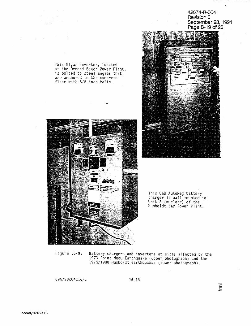
This Elgar inverter, located at the Ormond Beach Power Plant, is bolted to steel angles that are anchored to the concrete floor with 5/8-inch bolts.
This C&D AutoReg battery charger is wall-mounted in Unit 3 (nuclear) of the Humboldt Bay Power Plant.
Figure 16-9: Battery chargers and inverters at sites affected by the 1973 Point Mugu Earthquake (upper photograph) and the 1975/1980 Humboldt earthquakes (lower photograph).
896/20c04c16/3 16-18
coned/R740-ATB
42074-R-004 Revision 0 September 23, 1991
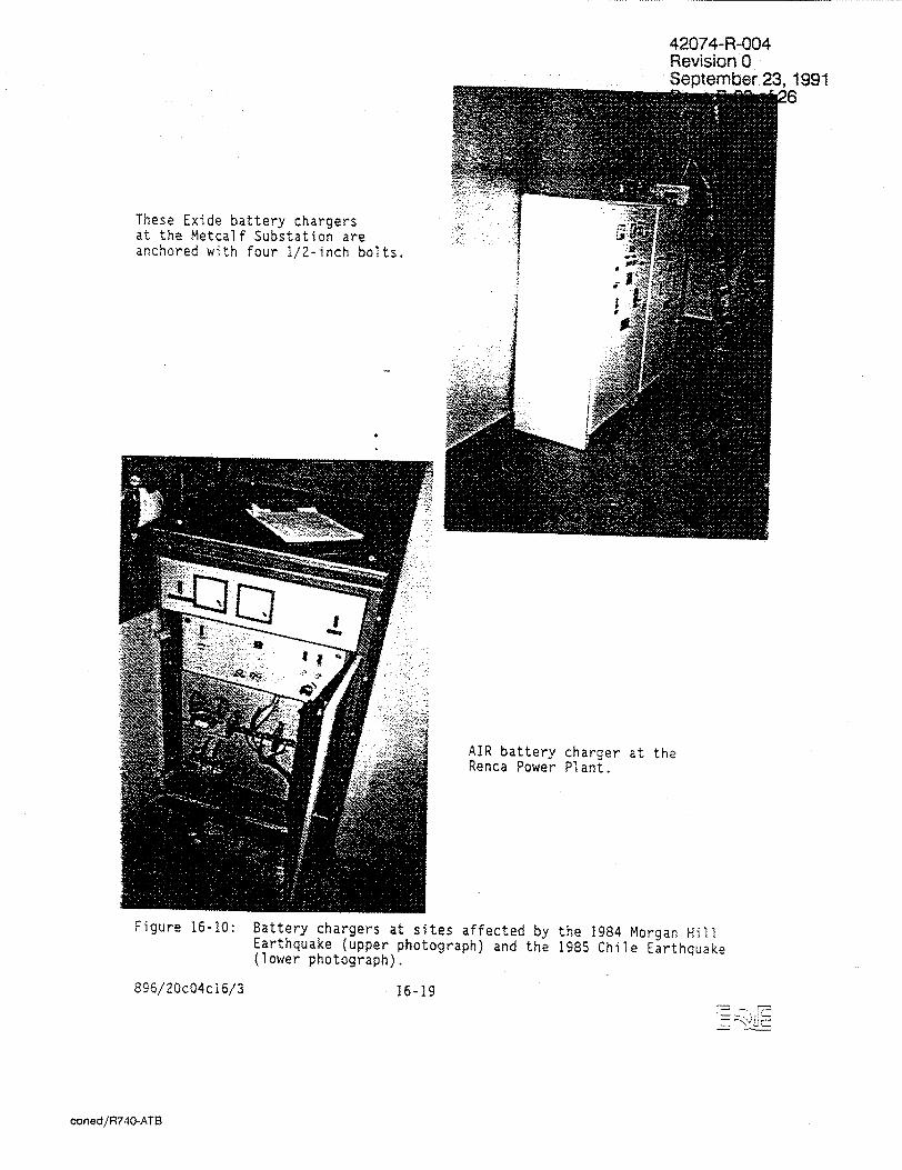
These Exide battery chargers at the Metcalf Substation are anchored with four 1/2-inch bolts.
AIR battery charger at the Renca Power Plant.
Figure 16-10:
895/20c04ci6/3
Battery chargers at sites affected by the 1984 Morgan Hill Earthquake (upper photograph) and the 1985 Chile Earthquake (lower photograph).
16-19
coned/R740-ATB

42074-R-004 Revision 0 September 23, 1991 Page B-21 of 26
Figure 16-11: Single enclosure UPS systems at Adak Naval Station. No units were damaged in the 1986 Adak, Alaska Earthquake.
896/20c04c16/3 16-20
coned/R740-ATB

42074-R-004 Revision 0 September 23, 1991 Page B-22 of 26
The Wells Fargo Bank Computer Facility experienced an estimated average horizontal PGA in excess of O.30g during the 1987 Whittier Earthquake. There are four Emerson Acu-Power UPS units located on the fourth floor of the facility. One of the UPS systems sustained five blown fuses Following the earthquake.
896/20c04c16/3 16-21
ure 16-12:
coned/R740-ATB

42074-R-004 Revision 0 September 23, 1991 Page B-23 of 26
Figure 16-13: At the Del Amo Substation, affected by the 1987 Whittier Earthquake, a battery charger (lower photograph) was tripped by the actuation of a molded case circuit breaker in the associated distribution panel (upper photograph). The breaker actuation was apparently the result of the panel impacting the adjacent wall.
896/20c04c16/3
coned/R740-ATB
16-22
S• •i•:•

42074-R-004 Revision 0 September 23, 1991 Page B-24 of 26
re 16-14: Examples of large capacity inverters, serving the UPS systems of the data processing centers, are found in the Emerson "Acu-Power" units at the Southern California Edison Dispatch Center, affected by the 1987 Whittier Earthquake.
896/20c04c16/3 16-23
coned/R740-ATB
42074-R-004 Revision 0 September 23, 1991 Page B-25 of 26
Figure 16-15: Anchorage failed on one of the Emerson "Acu-Power" inverters at the California Federal Savings Data Processing Center, during the 1987 Whittier Earthquake. The inverter slid about 2 inches, but was undamaged. The lower photograph shows anchor brackets, at thE base of the inverters, that were added immediately following the earthquake as a precaution against aftershocks. The remains of the original 3/8-inch expansion anchors are visible adjacent to the brackets.
896/20c04c15/3 16-24
coned/R740-ATB
CC
4. .4
C)i I LC uk
•0 - ýI.. • 1: .. ) C
Co . - . _ • C. ?•C ,r
•" .. ....... r ' ..
(Reference 4,Dawn o.921OF2X1)0
-~~~~~ -- ... . • ••o-- 00
"-0
•4 ' " .... LAM C"' ". .
:• :i.. "• - ' , . . . .
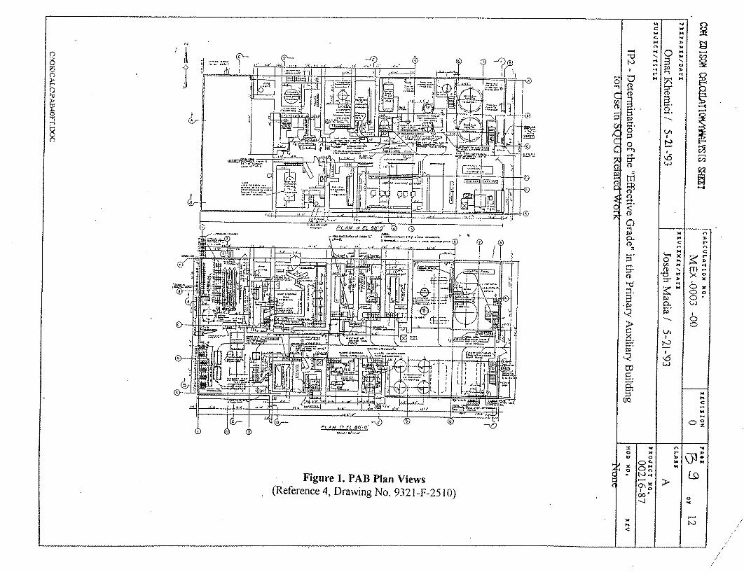
Figure 1. PAB Plan Views • (Reference 4, Drawing No. 9321-F-25 10) •
54 N
C

8
H go
* At th Well Faroo Bark Coute C or, a LkPS sygtem wtstakied &qe blown Iuhxa.
lndlaltaa A dmmoged uniA.
0
C)
0
(-4
I•
0W
Co
0
cc tu
ItJ
cc
0
cc 0
c4 C > X
cc
z
0 0.20g
400C 40 94 t4.4-0 C*0 f
al0.8Og
Figure 16-16: Selected inventory of static inverters and battery chargers within the seismic experience data base as a function of ground motion. All instances resulting in loss of function are indicated.
(gJn`
0.40g O.50g 0.60g
PEAK GROUND ACCELERATION (AVERAGE HORIZONTAL)
0.30g
Lfl
0.90g
M(0
(D 0 CD 4ý
03 ZI:0

1V-Ot1,L8/p0Uoo
£/9 tV0D0Z/962
Cr
CL0
*CD
"I
e- '
CD
LA -.,
-0
o M
(I
e-.
'* 0,
-4==
0.
=0~
= 0
S(0D
U
S0
o0
0
(0
mi
0 a z
0 0
-I"
z in
rn
0
0 z -'1
3-
0
0
0
0 (0=
0 .o 0
0
9Z .o 9Z-8 Ge~d L66tL '63 jeqwejdes
0 UOIS!A9eE tO0-1d-VLZOti,
NUMBER OF CHARGERS OR INVERTERS0
Adak Naval Station Las Ventanas Power Pant Renca Power Plant
Gates Substation Goleta Substation
::I: :: Glendale Power Plant Shurno•Bay Power Piant
Burbank Power Plant Mesquite Lake Facilty
Mesa Substation >& Metcalf Substation
Valley Steam Paant
Wels Fargo Computer Center*
n Substation .Rrnald Receivkig Station
SSylmar Converter Station Whitewater Hydroelectric Plant
7 SCE Dispatch Center J Pleasant Valley Pumping Plant
.Union XMain C~tzping Plants ~jSan Wdro Substation
F7 Ofinda Substation I C)
.z..1Devers Substation
SZ-91

42074-R-004 Revision 0 September 23, 1991 Page C- 1 of 5
APPENDIX C
COMPLETED SCREENING AND EVALUATION WORKSHEETS
coned/R740-ATC

42074-R-004 Revision 0 September 23, 1991 Page C-2 of 5
Revision 2 Status Y N U
SCREENING EVALUATION WORK SHEET (SEWS) Sheet 1 of 3
Equip. ID No. 2- Equip. Class 16 - Battery Charcers & inverters
Equipment Description BlqY/ve: y C •hg,Location: Bldg. F-• 7L. Floor El. 3 ' Room, Row/Col
Manufacturer, Model, Etc.
SEISMIC CAPACITY VS DEMAND 1. Elevation where equipment receves seismic input 2. Elevation of seismic input below about 40' from grade 3. Equipment has fundamental frequency above about 8 Hz 4. Capacity based on: Existing Documentation
Bounding :Spectrum GERS
5. Demand based on: Ground Spectra Amplified (Floor) Spectra
Does capacity exceed demand?
CAVEATS - BOUNDING SPECTRUM I. Equipment is included in earthquake experience
data base 2. Solid state type 3. For floor-mounted, transformer positively
anchored and mounted near base, or load path is U"' evaluated
4. Base assembly of floor-mounted unit properly braced or stiffened for lateral forces
5. For wall-mounted, transformer supports and bracing provide adequate load path to the rear cabinet wall
6. All latches and fasteners in doors secured 7. Anchorage adequate 8. Relays mounted on equipment evaluated -se.•. 9. No other concerns
Are the caveats met for Bounding Spectrum?
CAVEATS - GERS 1. Equipment is included in generic seismic test
data base 2. Meets all Bounding Spectrum caveats 3. Silicon-Controlled Rectifier (SCR) power controls;
wall- or floor-mounted NEMA-type enclosure
-3-3 1
) U N/A
AFS
O9N U
N/A N/A
N/A
U N/A
Y N 6ý) N If -)N
N N
U U U U U
7A) N/A N/A N/A
QDN U N/A
Y N U Y N U (ZA;
coned/R740-ATC
'j . " O'.J•
4.2074-R-004 Revision 0 September 23, 1991 Page C-4 of 5
Revision 2 SCREENING EVALUATTON WORK SHEET (SEWS) Sheet 3 of 3
Equip. 10 No. 3.~ Z Equip. Class 16 - Battery Charqers &-Inverters
Equipment Description &ý7T--gy
INTERACTION EFFECTIS (Cont'd) 4. No collapse of overhead equipment or
di stribution systems N U N/A 5. No other concerns N U N/A
Is equipment free of interaction effects? ON U
IS EQUIPMENT SEISMICALLY ADEQUATE? )N U
COM~MENTS
7-11e- 6J4 '9r ::ýr-rew I.S ýO~ raijoireeJ 40 ývc-c 4l-o.
7 I e s- 4 re, a )rsj no4 e i- tU 5 occ L)
7¾1- re- 5*..'s r a l it5. czr4te- n 4-t a i A A,,- 6- CLCC-1'6+ "' (/-~e-) 4 )E C"~
);jU wel 4 a -1 +L- 4xvo S'C-revi ar ,jk+4vJ 50i~;. C' "I hý .jJIM P4
Evaluated by: _____________________ at: ______
~KAO. Date:
coned/R74G-ATC

42074-R-004 Revision 0 September 23, 1991 Page C-5 of 5
Table 3-1
Unacceptable Relays (Appendix E of SQUG Relay Evaluation Procedure, MPR 1987)
Relay Operating Mode* References
GE CFD All
GE CFVB
GE CEH
GE CPD
GE IJD+ (none IE)
GE PVDII and PVD21
GE RAV11
GE HGA
W HLF
W HU (non 1E)
W ITH
W ARMLA W PMQ
W SG
ASEA ARMX-1
English Electric YCG+
Mercury Switches
Sudden Pressure Switches
Al I All
Al 1
All
All
All
(DE, NC)
All
All
All
All
All
(DE, NC)
All
All
All
1 (81-14/313, 82-26/348, 86-13/ 293),2, 3, 4, 5 (IN 85-82), 6
2, 3, 6
2, 6
2, 6
2
1 (84-20/352), 3, 4 (GE)
4 (GE)
1 (84-18/331, 86-15/269, 87-11/ 250), 4, 5 (IN 88-14)
2, 6
3, 6
1 (81-44/346 and 81-37/346)
5 (IN 82-55)
1 (85-16/247)
4 (ANCO)
1 (88-06/387)
2
1 (86-25/249), 2
2
REFERENCES:
1 LERS 2 Earthquake Experience Data 3 SAFEGUARDS Data 4 IEEE 501 Test Data 5 Notices, Bulletins, etc. 6 Induction Cup or Induction Cylinder Design * DE = DE-energized
E - Energized NC - Normally Closed Contact NO - Normally Open ALL - All Modes
+ Susceptible to damage; damage has occurred to this relay in an earthquake and it must be assumed that it will be inoperable following an SSE level earthquake.
960nb/chatch3 3-5
coned/R740-ATC

42074-R-004 Revision 0 September 23, 1991 Page D-1 of 34
ATTACHMENT D
BATTERY CHARGER ANCHORAGE EVALUATION
CONED/R740-ATD
42074-R-004 Revision 0 September 23, 1991 Page D-2 of 34
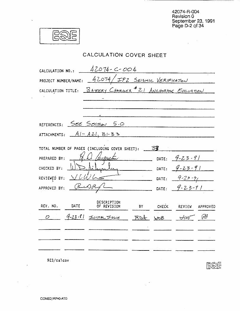
CALCULATION NO.:
PROJECT NUMBER/NAM
CALCULATION TITLE:
REFERENCES:
ATTACHMENTS:
TOTAL NUMBER
PREPARED BY:
CHECKED BY:
REVIEWED BY:
APPROVED BY:
CALCULATION COVER SHEET
4io74- c- oo4
IE: 47.7 P ~lc
A -925ll Z- A~io4RAtj- ýýVLUA 701,)
A I- A?! -3
OF PAGES (INCLUDING COVER SHEET)"
DATE: ,,, :- 3-9-i
DATE: -2- -1'!
DATE:
DATE: , 2-3-ri
DESCRIPTION REV. NO. DATE OF REVISION BY
923/calcov
CHECK REVIEW APPROVED
~i- -E:
CONED/R740-ATD
42074-R-004 Revision 0 September 23, 1991 Page D-3 of 34
EQE ENGINEEM1NG
CLIENT CX 6 z SUB&ECT 7~/¶2 ~ -~ /L
-74
+ 5, �CF�<c�Jczo5
SH~EET NO. z___
8y DATE _____,24
CHK'D WT- DATE 1-23-f)
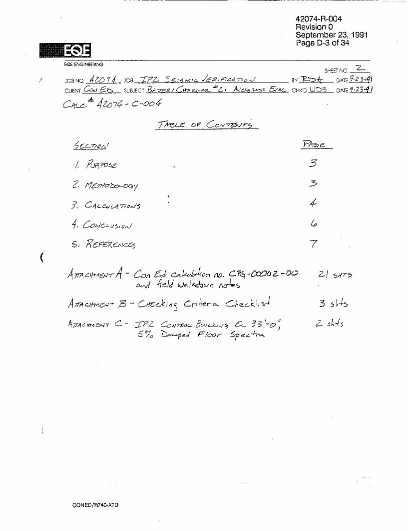
3
3
(a
7
14- cm C tier- c Aec)Ja
A 7rA 6) jr4&1, T ::1 -7z ~ zO/ ~~~ 5L. 3 3
` %
CONED/R740-ATD
(2-i SY75
13 sb-15

42074-R-004 Revision 0 September 23, 1991
1______ Page D-4 of 34
EQEEIGNERNGSHEET;NO. ___
JOB NO.Z07 -:C8 P 5 ,5r~1.5mi V~zir1/::-r1QAj1s DATE____3
CLUENT S&ET y2 AI ý'~6~ CHK- Di:3 DATE ±3
(AL~ 44D n4 Y-c
I.JL c4e- 4); 0-/ý1 evaýuJ 4 -2 ;4J,10- ý-lr/
-4 f '
~ 2~~~~ZA -- ~~/(~7 'sLzJ6 7 ' 5/Cf
CONED/R740-ATO
C.

42074-R-004 Revision 0 September 23, 1991 Page D-5 of 34
EQE ENG~NEEP1NG
JOB NO -7___ JOB ,cai~~ /~~7 CLIENT !C-IA fc SUBJECT ~A6~2-) !A~~~AL
SHEET \4c.___
CHK'D ý/JblA- DATE LU
c - CA ý-C- u'
Sý4 Az I Lc0l/h aZS 4)W5
-F~-cM pjý- Ao l
Qt4$S
____ ___ ~ e 5-c
-305
(45",
-r�-�--� �.
3 60~ 4
-74-S
>105
-~~~, -2,~ 0~ (.) 4 ,/4, ±1,.~4
Pý 'ýIlja c e /?-rlýl Iy-4
4ý 3 0 0_
i~'a7- 2-~v Z j/ 7~~ -7f))
4-u Z L~
CONED/R740-ATO
/
7b
loc-r--leS ýý44Z-f-k/ ,me-Lr-
EQE ENGiNEERING
2CB NO.______ J08 2Y- 7ic:Vr/c72, CUJENT 6Pt>\ SUBJECT EA 77/ A~CZ-A5 AL,
(,ifx #-,'42ýD74- Oc4-0 L
F,- 7ý4/, -ýRclý ) 4,
42074- R-004 Revision 0 September 23, 1991 Page D-6 of 34
S ETNC. ____
BY Ll DATE____
ClHKDC) W)Pa DA7c 1,13.41
Fe=2-aO.k t J -=-2 -1 ,D4 74 r
~)~4 7e ~s/~ 5 f#~DLqCe/Y'-''
g~ 4,d 4c3
(Fe T -W e -
/ 7 0b5 , Z 05/t
73 /171, 0 O
C, 'Z 7
CONEO/R740-ATD
`> f= . = ) 7),5
F,, - Z-Z- ý, / -" rý,) ;- / 3 3-7'ý'1,5- -7

42074-R-004 Revision 0 September 23,1991 Page D-7 of 34
EQE ENGINEEP¶NG SHEET NO.____
OUENT~n$ SUaiECT BA77i~ . #zI Aj~~ 6V,4L,. CH'D, T___
C4L ýo 74 -C-64
tjer C4v~rA!CjIJS/OA
~ ~ ~ X'4c~ 4 4
-/4ea&-ý b4
CONED/R740-ATD

0 z
mm
A-A
(AKLA -u n 00
% 0
CA)
L))

42074-R-004 Revision 0 September 23, 1991
Page D-9 of 34
SEP t3- FR 3:20 ID: Ta NO
RECEIVED SEP 1 3 1991
FAX TRANSMITTAL LSHEET
ATTACHMENT A SHEET /•)DATE:&19 CON EDISON
4 Irving Placc - Rat. 1028 FAX NO,.U II2 7 85 Z Civil Engineering Dept. New•,Yo:rk, New York 10003
CALC. NO. 42 0 7 4- -C- 004FROM: JOHN SKONIECZNY
TELE: 212-460-2794 -
STO:1 P•. A- AuC) -rJ
COMPANY NAME: -
FAX NO. 7 75-74' -7 7)
SPAGE 1 OF , • /
(INCLUDING COVER SHEET)
COMMENT
CONED/R740-ATD

42074-R-004 Revision 0
September 23, 1991 Page D-10 of 34
*SEP-13-'91 FRI 03:2! 10: TsI- NO: ~ rsls P2 CON EDISON CALCULATION/ANALYSIS Palq I of
COVER SEEET
;ubsection" GENERATION STRUCTURES Code- CPG
;alc.No.; CPG-00002-00 Calc.Type: SEISMIC QUALIFICATION
Citle. FU3DASMENTAL FREQUENCY Or WESTINGHOUSE #21 BAT"TERY CHARGER
?roject: 69982-RA Modificationf: NONE
)ocument ?age Count: 010
TAG NUMBERS
(none)
. * * COMPONENT(S) AFFECTED * * *
Equip.Type 007 BATTERY CHARGER
Structure 08 CONTROL BUILDING
System 18 BATTERIES AND DC DIST
Class (Check as appropriate): A age __ NET ___ __ Non-CiaBB __
Preparer/Date Reviewer/Date Approval/Date Super- Confirm.
(Print/Sign) (Print/Sign) (Print/Sign) Rev.No. cedes Required? -- -- - -- - ----------------- --
Concurrence (If Required)
ATTACHMENT A SHEET /
CALM NO.'42D1L1--Crn004-
CONED/R740-ATD

034ICTIVI
-70 o;:- T-Lý 1ý-_ &A -1,rS.Ry
ATTACHMEN'T A u *EET CALC. NO. 42 C)74--.Cm Clo4-
111six lasts 443 197TASNCTS
A
C>A mjEpj T-AL-
42074-R-004 Revision 0 September 23, 1991 Page D-1 1 of 34
03:2! M, ..... TF-1 ý40 , wjltay -Ooccl-cc
Uj -Z
týkm erj T"A-1- F-Q-elýz u W F,-4,r Ira Q n, %-W ?- c to
7.ý4e 6'a'TISay Ae-r 14-6A 61,11týftl CAVT-/"FVf-,e
T-0 -mo r-94m i4L-. (4.jrý Rwr- 774t L4 S'Dg- sm (, rclqc-. . & Homf.-ýoF Z7,-jiz--r1p tr- rtJi AtJb
0,-1 1'2- (.rc.1 V S jLz -,10 CA 1. 4 Lc,.,4Tr, J-ý 15 aA SLC CA ý- iý)ErrcrLMW&c ý r
Wf4((-94 tS M 7t#- OAiU- I/J vý F-j A, S9AQf- tVIE '1eT-A4-0U-CX-- C- ý-(r'ý26dlt
sezvIct- 7-tqf- F-RecNetackr' 14 Cxc,,-VLýýr) LA"'X:, r-ýe
CONED/R740-ATO

42074-R-004 Revision 0 September 23, 1991 Page D-12 of 34
___ ___ __ :-ý -D *10 -0
c. a.a
14
SATT, CHAJEN• A HE1-T4
z
0
44
S..,,,
CONED/R740-ATD
---------------------- . ........ -
0
0 0 0
a z 4
-4
-4
U -. 4 4
42074-R-004 Revision 0 September 23, 1991 Page D-1 2 of 34
*19 P0
- - - . � �- � ----------- � I I
43 0 in
C
4 -4 U
'-4
C
4��
bd 4
ATTýCHýAENt A
CAL-9 ).N. -42 074- C
_________ 1�
? i - -_ i- -rtI
____________________ J -___________________ 2. Z� L.Z.....
CONED/R740-ATD
9
-0
SHEýT Af-
.4
-S z 0 '-4 I.4
0
0 z 0 en 4-4
z .4
0 z a '-4
'-4
0 �hi
SEUz-13-'91 FýZl e3:2-2 ID' Te- No e' A I * -A 079 - 0 0

42074-R-004 Revision 0 September 23, 1991 Page D-13 of 34
TM- NO:
CON EDISON4-CENTRAL ENGINEERING CALCULATION/ANALYSIS SHEET
STAT IONAJNIT CALCUL.ATIOtM NO. PAGE
2P 2- 1 .ZGox2O 4- a-PREPARER/qATC ZEEEWR/DATE CASS ( .P Ct&.Y)
SLO...CT OF COMPUTATION4 MOO NO./p~ej. 1N0.
compaNENT DES= XPTION
N~FLYI. p; -- - -7
tIV4,~
LFRONT
sll:ý
PLAt-J OF SA-r7EPr C,4,96.Z
F-A L L- . Aý4 e.O'ýV4 S
ATTACHMENT A SHEET .45CAL 'o. NO42o F-7T-C-ocxl-
CONED/R740-ATO
__j
SEP-13-191 FRI W,.22 'D:
7-
590PI r-IF-L-b or-

42074-R-004 Revision 0 September 23,1991 Page D-14 of 34
SEP-3-'l FI e3:23 10:
�A'r� �AS:CCLL�-�J F.�A�ML
V
�
I I
ff.
0
++
CALO. NO. 42 074- -Cc4
- ~ ~ e to,7 + 7 8OSV
CONED/R740-ATO
TEL. NO -
CON EDISON-CENTRAL- ENGINSEEING CALCULATION/ANALYSIS SHEET STATIOHA/tRIT CAL~CULATION NO. PACE
PREPARERJ'QATE PEVIEWER/CATE CLASS (I.*P. CNL.Y
SU&~ECT OF COMPUTA-rxcN MCO NO. AVOJ. No.
COPO~NEN DESCRIPT ION jLr8eCJAg At~
Z,-JeýZ-IfA Cl) ;:j,,jL
7(;

ATTAC
CALO.
TZAý- c4-ti~ (2 J I a ,,4j 10 T
eL~o S-c#H A-4F. S 744 '7A ER AX -rý TVP r,.
~r SHf4 Fr .s LA.4 Sr r-j;5 ;V~e I IL ;f
CONED/R740-ATD
42074-R-004 Revision 0 September 23, 1991 Page D-15 of 34
SEP-13-'91. FRI 0323 ID: e-'4.;*1 0
CON EDISON-CENTRAL ENGINEERING CALCULATION/ANALYSTS SHýEET STATIOt*A*'4T CtLACNNO. PAGE
PREPAPR/RIqATE REV IEWESjDA TE 6 5-iCL~ASS (C PONLY)
SU~kECT OF COMPUTATION MOO No./PROJ. No.
COMr'CMNT DESCRIPTION I
~~-e z- 4~Rr C.Ag&L
+ 1 z S) (itis) + 627S nI'2JA /zP)
~HMENT ASH T% zt\4 t-6+
NO. 42 o-74- oc4

42074-R-004 Revision 0 September 23, 1991 Page D-16 of 34
SE-3-'91 FRI 03:24 ED *18 Pee
CON 5DISON-CENTRAL ENGINEERING CALCULATION/ANALYSIS SHeET
STATICKA.VIT FCALCULATION NO. PAGE
PRi PAREER/OATE CLASS (IP.ONLY)
SUBOECT OF~ COWUTATIO MOD NOi'PRO.J. NO-.
coMPtEN? DESCRIPTION
AMLCA 2 CA*P'r
ATTACHMENT A SHEET A~
M A, CALC4: NO. 420o74- -C- oc)4
Vsl 10c~$ 6ZS Z1,4 7 t3 0'(3c a; 7
12c5
x cx, 7q,
k 0l 41,R .M
IV
-rSVS
CONED/R740-ATD

To cs
sa!ý 6 7E
5Aý 1-70*'
C0,jr-iooj Tu;_ C_'ý cAJ
PE'afýalylstm A sto;(),urr- Lv 1-. es r7MAýTf- 0 jr- IVE
71LAt'I.Sr_02'"&lZ R%ý
e
00
10AA-r A EA Lq tV 1414 Lt UJ 47U E-S
CONED/R740-ATD
-1 ------ I ..................................
42074-R-004 Revision 0 September 23, 1991 Page D-17 of 34
:*Is Peg -
CON EDISON-CSNTPAL ZMGINeEPING - CALCULATION/ANAL.YSIS SHEZT
$TATION/UNIT _-TC-11""ATION NO. PAGE it) =:92- I C PG -00ca 2. - Cc & -OF
PREPARER/OATE REVIEWER/OATE CLASS (1.9.aNLY)
'4f , 'V U sLeJECT OF CCWUTATkl.;N MOO No./PRW. NO,
COMPOWENT OESCRIPTION
tLAý eAAd'we'..P
SEP-13-'91 FRI e3:24 ID:
A17ACHIME-N-11- A %*:HEET'A') (D MoTCP,(r-ANý Ar 70P of: CACý,wfr:
-Z C4jýqS F ev4rrUf; r E c,-r/,_f4rE4 JV Aý7- Nrl- WEJ4,47'
TPIS mcrTvr2, ts 400
7R A NO. 42 o74 oo4
AoM A 7oTAt- 0/:r
NO 6ov,_o SOL Filt,,P40
TR"sme-mE4e. j6A,ý C0,j7ALr?,J6, W)Ei5r7,JGHDU.SE,
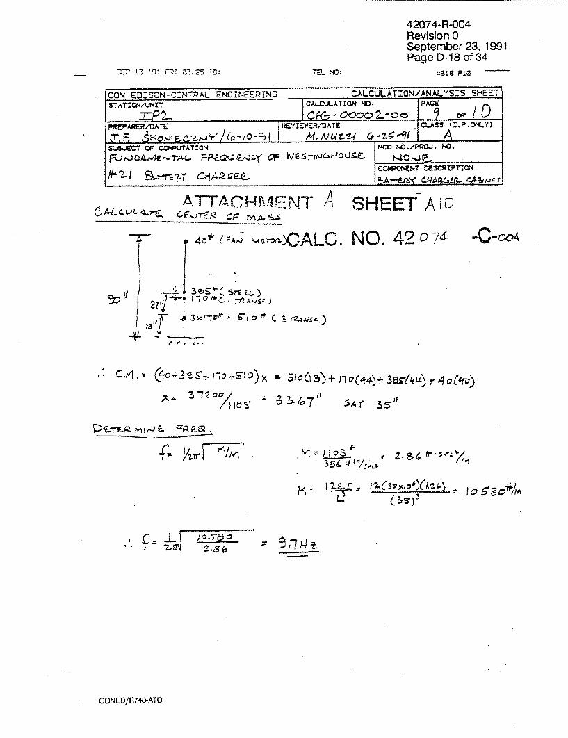
42074-R-004 Revision 0 September 23, 1991 Page D-18 of 34
CO6N EDISON-CENTMAL ENGINEERING CALCULATION/ANALYSIS SHEET' STATIOtN4AJNIT CAMCU.AT1014 NO, PACE
2I. C 8 - Cc'c2.-o a0 C- DO Pi~EPARER/OArE REVIEWER/DATE CL.ASS (IPQLY
SUBOECT OF COWUTATION M'OO NO./PRW.. NO.
C-PQNET DESCRIPTION
At .1 - ATIT16HRAENT A SHEET AIQ)
40 7FA 4ý- ~o r-:;? ALC.
9, CYýl,- (c+3.T~+ r~o+S-))x
D -s mt4L- FAF-z
A�r � M- = Ios "1-
7- Fri ______________ - �
CONED/R740-ATO
FR 325 ID: a- NO:
NO.-A 92 074-r -C-004
Xt~= -2 /10
-F
5 A r 35.5i- -3 '!)- &7 li
I./) z )I" - - 10 9804//A
Lý - CýS-)3
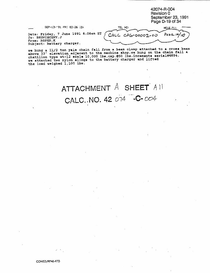
42074-R-004 Revision 0 September 23, 1991 Page D-19 of 34
SEP-13-'91 FýRl W:2S !D:f._ _ TE---- NO."•
Date: -'riday, 7 June 1991 6:06am ST CA.- •&-Jc/-o rot: KONIECZNY.J Erom: ROPER.K Subject: battery charger.
we hung a 11/2 ton yale chain fall from a beam clamp attached to a crons beam
above 33' elevation adjacent to the machine shop.we hung on the chain fall a
chatillon type wt-12 scale 10,000 lbs.cap.@50 lbs.incements serial#48 9 4 .
we attached two nylon slings to the battery charger and lifted the load weighed 1,100 lbs.
ATTACHMENT A SHEET AII
CALC..NO. 42 0-74 -C- wc4-
CONED/R740-ATD
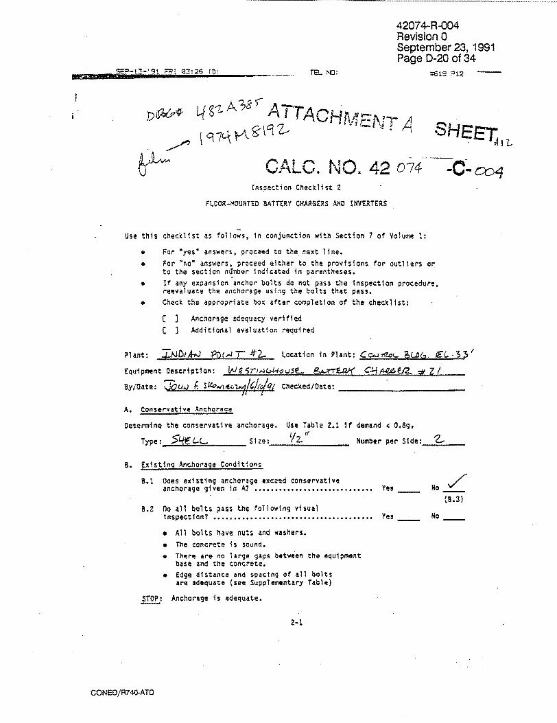
42074-R-004 Revision 0 September 23, 1991 Page D-20 of 34
.S.-13 !'91 RT 03:2S FO: TF. NO: *IS ,12
I ~~3 5w ATTACH~j1="~ SH~
CALC. NO. 42 o74 Inspection Checklist 2
FLOOR-MOUNTED BATTERY CH4ARGERS AND INVERTERS
Use this checklist as follows, in conjunction with Section 7 of Volume 1:
"* For "yes* answers, proceed to the next line.
"* For 'no* answers, proceed either to the provisions for outliers or to the section number indicated in parentheses.
"* If any expansion anchor bolts do not pass the inspection procedure, reevaluate the anchorage using the bolts that pass.
"* Check the appropriate box after completion of the checklist:
C J Anchorage adequacy verified
C 3 Additional evaluation required
Plant: ZNDi-A,-J n)O,41: 4ý-2. Location in Plant: Cc fZo,. B (,. XL.3
Equipment Description: W r'E 5",,-1W SL. 9,_ Ariaf C"A.2 . _•
Bly/Data: 70,w,) ( S~4C0A /#1 /(, / Checked/Date- ______________
A. Conservative Anchorage
Determine the conservative anchorage. Use Table 2.1 If demand ( 0,8g.
Type: _ -L. Size- V2_ Number per Side: 2
B. Existing Anchorage Conditions
3.1 Does existing anchorage exceed conservative
anchorage given in A? I................................. Yes No
(9.3) 8.2 no all bolts pass the following visual
1nspection? ....................................... Yes No
# All bolts have nuts and washers.
* The concrete is sound. e There are no large gaps between the equipment
base and the concrete.
e Edge distance and spacing of all bolts are adequate (see Supplementary Table)
STOP: Anchorage is adequate.
a-i.
CONED/R740-ATD
............

-•3-'9t ;-RI 0-3:27 [D:V
C
42074-R-004 Revision 0 September 23, 1991 Page D-21 of 34
*1iý F=-E- NC:
ATTACHMENT A SHEET A 8.3 Type and size of fasteners (see Mote U,)
Are fasteners located within 2" of the 'f /
outer corners of each cabinet? ................... ys
Expansion Anc or Bolts
Shell: - Nonshell.: Unknown Diameter
Does each cabinet in the lineup have at least . two bolts per side (see Note 2)? .................. Yes
None or Other: Go to provisions for outliers.
8.4 Dimension of one cabinet in the lineup (see Notes 2 and 3):
Height ........................................
Depth ............................................
Leng th ....... .... .... ................. ... .. .
Aspect ratio ...............................
8.5 Are L 64", a 4 40", and H/1 e ? .................
B.6 Is the center of gravity approximately at midheight? ................................
S //
Yes No
Yes O
C. Demand
Record demand for this location in the plant ....................
0. Screenino Procedure for Expansion Anchor 8olt Anchorage
0.i Determine anchorage capacity, G, from Screening Figure 2.1 or 2.2 ...............................
0.2 Is demand less than capacity? . . . .... Yes / o
0.3 Are edge distance and spacing of all bolts adequate (see Supplementary Table)? ......... Yes No
0.4 Do bolts pass the attached inspection V.,.
guldelines? ...................................... ...... Yo
STOP_ Anchorage is adequate.
Notes T.--Tf values vary, use minimum. 2. See Section 7 of Yolume I for an alternative approach for multicabinot lineups.
3. If values vary, use mAximum.
pALC. NO. 42 074-
2-2
//
CONED/R740-ATD
--00o4fL

42074-R-004 Revision 0 September 23, 1991 Page D-22 of 34
:6-8 P14SER-=-t0-'91 CI OJ:3Z.- ID- ,. TE NO:
ATTACHM"ENT A SHEET A ',4
CALC. NO. 42 o074- -C- of4 Table Z.1
CONSERYATIYE ANCHORAGE FOR 3AflMRY CHARGERS AND INYERTERS FOR DEMANO - OSS
*See Screening Figure 2.1
2-3
CONED/R740-ATO

0 0 z m 0
1-1/4' typ
1 -/44 typ
B 40^ Density 4 45 pcf
II
L 64=
Battery Charger Base PIan
3.0"a
Id
4-a
U
ILI
U,
3.0
2.5
2.0
U15
d'
-t U.,
,U
-5
Cabinet Width, B (in.)
3/8- BOLTS
H/3 - 2
I IHIB I' 4 F1 -- H .0 15 20 25 30 35 Cabinet Width. B (in.)
15 20 25 30 35 40 Cabinet Width. 8 (tn.)
Screening Figure 2.1. Screening Criteria for Floor-Mounted Battery Chargers and inverters Anchored with Shell-Type Expansion Anchor Bolts
>) >
O i
Z m ro .
3
40
03
to
CA 0
-,0
(D CD
0.5
/ I

-I3,0
00 z m
0�
U 4'
4'
U
fri
I) i-i
3.0-
2? 20
S1.0
0.,5
3
Cabinet Vi~dth, 8 (in.)
v-I-~-I ~
N
5/8' BOLTS
0/8-KiB - 3
kf/B -4
*toCabinet Vidth. 6 (in.)
15 20 25 30 35 Cabi net, Width, 8 (in.)
Screeninq Figure 2.2. Screen$ing Criteria for Floor-Mounted Battery Chargers and InVerters Anchored with Nonshell-Type Expansion Anchor Botts
>
m
mo: <D 0
CD
(D
CA)O
1-1/4* typ
a 0 1- iI4'typ
aB 40"j Density < 45 j pcf
Battery Charger Base Plan
3.0.
N di
U
4'
44
40
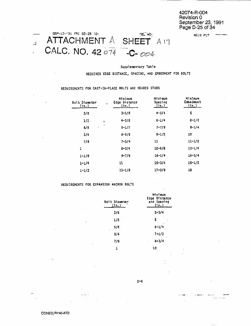
SEP-13-'91 FRI 03:29 ID: TEL',:
- ATTACHMENT A SHEET A v. CALO. NO. 42 074 -'C- c4-
42074-R-004 Revision 0 September 23, 1991 Page D-25 of 34
*19S P!7 -
Suplementary Table
REQUIRED EDGE OISTANCE, SPACING, AND EMBEDMENT FOR BOLTS
REQUIREMENTS FOR CAST-19-PLACE BOLTS AND HEADED STUDS
Bolt Diamee~r (in.)
3/8
1/2
5/8
3/4
7/8
1-1/8
1-1/4
1-1/Z
Minimum _ Edge Distance
3-3/8
4-3/8
5-1/Z
6-5/8
7-3/4
8-3/4
5-7/8
11
13-1/8
Minimum Spacing
(in.)
4-3/4
6-1/4
7-7/8
9-1/2
11
12-S/8
14-1/4
15-3/4
17-3/8
Mii mum Utbedment:
6-11/
8-1/4
10
11-L.Z
13-1/4
14-3/4
16-1/2
18
REQUIREMENTS FOR EXPANSION ANCHOR BOLTS
Bolt Diamter , ifn. )
3/8
1/2
S/S
3/4
7/8
1
Minimum Edge Distance and Spacing
(in.)
3-3/4
6-1/4
7-1/2
8-3/4
10
CONED/R740-ATD
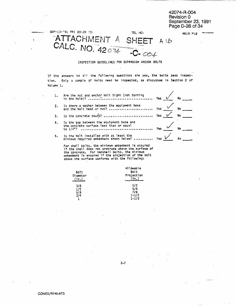
42074-R-004 Revision 0 September 23, 1991 Page D-26 of 34
. .. •- -' FRI 03:29 ID[: T. ýC:
-ATTACHMENT A SHEET A
CaLC NO. 42- 0.
INSPECTION GUIDELINES FOR EXPANSION ANCHOR BOLTS
If the answers to all the following questions are yes, the bolts pass Inspec
tion. Only a sample of bolts need be inspected, as discussed in Section 2 of
Volume 1.
1. Are the nut and anchor bolt tight (not turning in the hole)? ....... ..........................
2. Is there a washer between the equipment base
and the bolt head or nut? .......................
3. Is the concrete sound? ..........................
4. Is the gap between the equipment base and the concrete surface less than or equal to 1/40? .........................................
5. Is the bolt installed with at least the minimum required embedment shown below? ...........
For shell bolts, the minimum embedment Is ensured if the shell does not protrude above the surface of the concrete. For nonshell bolts, the minimum embedment is ensured if the orojection of the bolt above the surface conforms with the following:
Bolt Diameter (in.)
3/8 1/2 5/8 3/4 1
Yes
Yes
Yes
Yes
Yes
No
No
No
No
No
Allowable 801 t
Projection (in. )
1/2 5/8 7/8
1-I/2 1-1/2
2-7
CONED/R740-ATD
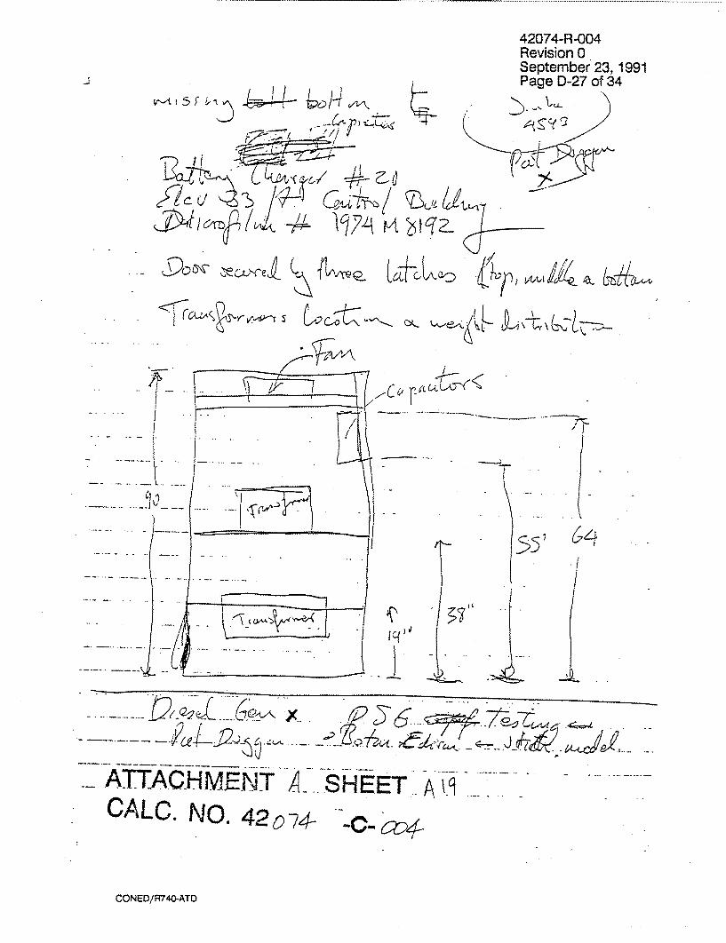
FG / ~I~A
,P /1 12
k
.
.--...
,. .
S .... .. .. _ -- .7 :•. -- 3' • <
.AT'TACHM.H.ENT AI SHEET. . CALOM NO. 42074- A--
CONED/R740-ATD
�.1��
Vtillz/4,e- ýý
42074-R-004 Revision 0 September 23, 1991 Page D-27 of 34
~c(23

F
ATTACHMENTA SHEET AZFa CALC. NO. 42074 -C-co4
INSPECTION GUIDELINES FOR EXPANSION ANCHOR' BOLTS
,2074-R-004 Revision 0 September 23, 1991 'age D-28 of 34
If the answers to all the following questions are yes, the bolts pass fnspection. Only a sample of bolts need be inspected, as discussed in Section 2 of Volume 1.
I. Are the nut and anchor bolt tight (not turning in the hole)?.
2. Is there a washer between tbe equipment base and the bolt head or nut? .........................
3. Is the concrete sound? ............................
4. Is the gap between the eqjipment base and the concrete surface less than or equal to 1/4"?
5. Is the bolt installed with at least the minimum required embedment shown below? ........... For shell bolts, the minimum embedment Is ensured If the shell does not protrude above the surface of the concrete. For nonshell bolts, the minimum embedment is ensured if the projection of the bolt above the surface conforms with the following:
Bolt niameter
3/8 1/2
5/8 3/4
i
Yes No
Yes No
Yes i No
Yes NO
Yes No
Allowable Bolt
Projection __n {i).
1/2 5/8 7/8
1-1/2 1-1/2
2-7
CONED/R740-ATD
M,

42074-R-004 Revision 0 September 23, 1991 Page D-29 of 34
Li
ATTACHMENT A SHEET
/� Y-Ž
CALC. NO. 4,2 07)4- -cm oo4-
CONED/R740-ATD
A2-1

42074-R-004 Revision 0 September 23, 1991 Page D-30 of 34
A 7746/1.- B 5i i
C4ECKING ClT•1A CHECK<LIST
Cilent CAI Pro Job No. ___ __ __cal
Re' C'ýteria Yes
-1. Originiator followed defined pro. cedures
2- Title, Purpose and function of ]
the work checked are adpquately / described
-3- Work method clearly stated and I/ Sappropriate
4. Assumptions identified. Opeon items flagged for Subsequent verification
where necessary.
7. Technical bases and references current . ce ofy sele wded and incorporated.
t. Technical input prperfy selected and b r adequately identified. Any specific inr to be excmnuded are adequately identified.
7. Applicable codes, standards and regu
latory requirements Identified and . gproperly used,
8. Analytical steps can ne verified without S reccurse to originator.
traceable to Originator, date and job or equivalent control number
10. All markings legible and identifiable t"
1 1. Work clearly references any ffna! suppot ling computer runs
12. Final computer runs iniclude input listing
and output
13. Final computer runs contain unique number identifier
Nject. A rc_ 4- , -o
c No. 42?0-07 4-C-oa4ision No. O
CONED/R740-ATD

42074-R-004 Revision 0 September 23, 1991 Page D-31 of 34
(Cantiriue~o)
Client C^O/,,f ý5
Job No. 4Z-O74Project A~cjozex azrp A-
Caic No. --Z0~74(-C-Ond
Revision No._____ _____
Yesl No IN/Al
Checked by:Date: 6ýL"16L31
CONED/R74G-ATD
42074-R-004 Revision 0 September 23, 1991 Page D-32 of 34
C,-&. 430.D74- - c ,# CHECKINQ. QCfTrERTA CHEC,-KLIST
(Canhinued)
fcrM317.9c=c
CONEO/R7440-ATO
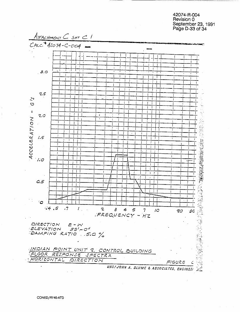
42074-R-004 Revision 0 September 23, 1991 Page D-33 of 34
1 A~r pietf&,4r .$ft-Hr (-• /C,.tr--*40o74 -c-oc,,4
Z. s22
0
tU -J '4, C) C)
I. .6
jiz
Os.7
/ z ~ ~7 /0 -*Z
eL/VT/ c c 710,.OE
DcAMOPING gZA7-/C 5.
./AhClAN liO/Ntq UNI-T '2j CONTRZOL /5U!II-IDNGC :FL-OCR /ZcJ> Ns~e ~INOC7T/A 8O'Q/ZION'TAL. D/IZcC7/, FIGUR/E c
URS/JUHN A. OL UME & ASSOC/ArTE-S El/.GINEIF-A;..
CONED/R740-ATD
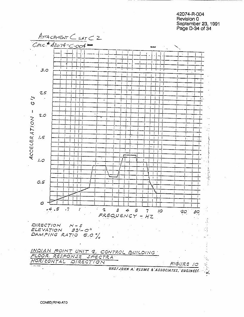
42074-R-004 Revision 0 September 23, 1991 Page D-34 of 34
&4-~ -*4 0 -74 x-,f~
0.5
C45* .7 / a 7
P/~U~CY -HZ
C/0/9.TQ S-S710N 4ELEVA7O TICS 3~-9 4DAMOING P.A7/C0 6-0/ 4
/NC'/AN /lac/NT N1 C0OV7-IL 15UILIDING -FLOOIZ. /?G10OGNSJEP~T~ A'O/ZI/CN7AL C/ZlECT7cO FIGUR~E /0
UR-71JOHN A: H(UIMc ASCAESiI~
CONED/R740-ATD
3.0
N.
0�
U) -�2
0 0
/.s.

42074-R-004 Revision 0 September 23, 1991 Page E-1 of 4
APPENDIX E
BATTERY CHARGER 21 PHOTOS
coned/R740-ATE

42074-R-004 Revision 0 September 23, 1991 Page E-2 of 4
Figure E-1: Battery Charger 21
Figure E-2: Typical 1/2" shell anchor bolt
coned/R74G-ATEME

42074-R-004 Revision 0 September 23, 1991 Page E-3 of 4
-- TOP
-V.
BOTTOM - -
Figure E-3: Internals of spare battery charger similar to Battery Charger 21
coned/R740-ATE E I ZWIý
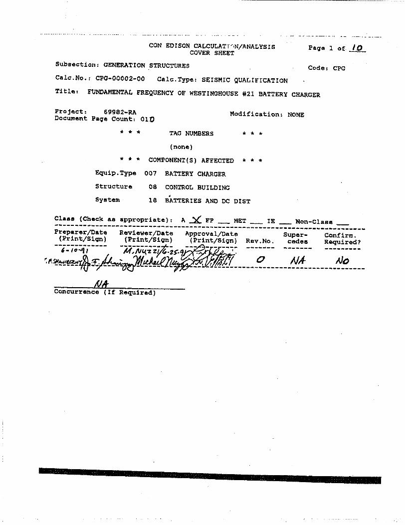
CON EDISON CALCULATT',N/ANALYSIS COVER SHEET
Subsection: GENERATION STRUCTURES
Page I of -_10
Code: CPGCalc.No.: CPC-00002-00 Calc.Type: SEISMIC QUALIFICATION
Title: FUNDAMENTAL FREQUENCY OF WESTINGHOUSE #21 BATTERY CHARGER
Project: 69982-RA Document Page Count: 01)
Modification: NONE
TAG NUMBERS
(none)
* * * COMPONENT(S) AFFECTED * * *
Equip.Type 007 BATTERY CHARGER
Structure
System
08 CONTROL BUILDING
18 BATTERIES AND DC DIST
Class (Check as appropriate): A _ FP _ MET _ IE - Non-Class _ ------------------------------------ , . Preparer/Date Reviewer/Date Approval/Date Super- Confirm. (Print/Sign) (Print/Sign) (Print/Sign) Rev.No. cedes Required?
----------------- ----- ------ ------- ------ --------
Concurrence (If Required)
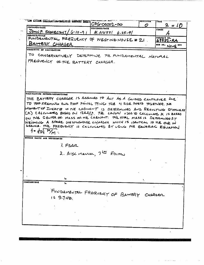
CLASS
Zomorm
Not r-p-Muraocy Cf 19 1ý-2- -&A Q4AA6M *99 me. Rev
OS4$&CTfVg Of
TO CONStRVATIVE.ý-Y ZýVrEERMIQ6 F--'-IbAmErJ7-.41- /,14Twý,41
CALCULATION
-rNF BA.T-rErzy cqAaccp- is A-4,svmkz 7"0 4e-r A6 A 6K.,meD gýAric-F6,f pT'O TOP J=RA^,N;(* Ajh Rl;or- FllýrJLL TýiJC-7 7WI 44 5109. Posrz TvGrc'7%4kR. 7QF
t-40ME-'-170F XrJlF.P-r/P IF rUf CAGINIEtalr f-5 DrlrF9PllrJEO AfJbI RrCelVfrfAJ&' grIACA.If-SS CK) CAL 4w%-AAV-b RASOýO OIIJ ISLr/O, 7t*- CIP46n4 VSCO -0 C-M.4.",ý'ATf, j< /S 8A.S04 O#j TO& C E^jTfA cP MAsS or- rl/f- CA.VJ"7-. WL T07-AL MASt Is OE rrmmw&o A r
A SPAgf- Cý14,446f/t WWltq PS JUVrICA.4- rV TLX 0,W /,.j EZvicf-. T%4F- MecpjftJcr /-s cAcýevLýýO 6,1,1 L/SwG r4t Gapýýelz-A-<
SIS &No
PsAa
2, A- i 6c. t-)AIJVd- I n VAJ


FA0fJT
CON EDISON-CENTRAL ENGINEERING CALCULATION/ANALYSIS SHEET STATION/UNIT CALCULATION NO. PAGE
mp z I cp&-oowZ-00 4 or 10
PREPAAER/QATE REVIEWER/DATE CLASS (I.P.ONLY)
TF. SkwtF4?,wf le,- lo-")l SUSXCT OF COMPUTATIOW MOD NO./PROJ. NO.
FJtJNAMENr.4L- Fq"UF,,44,Y OF: COMPONENT DESCRIPTION
'ý2-1 i3-4M RY CWAP-(.C--P- OArM4Y 14AI26fit 4ASific-ri
tz 11 s 11
I4
PLAtJ oF 13AT-rER,( CqAg6fia
FRAMIN* (WE,5-rjj& 1ý10VSE)
'14' ALI,- bf m IL4 IS f0tJ SFROM F I F- 1ý b M f A'S v 12 F- vi fG.;7- o r-
SPAA& K/LSriý,&Noula U'r'r'FliY d(lA(2e.FfL
ruý) 4 0 (VIO)
GlrM
OW

N�,jA CL?� r�v�- oa LSAS "
COL~'-~q F~nAML
(V I -I
'5/7s4 L.
'11031
+ a 5t2S1 I 2 r..7 r1 (,lr it7SY i TS .- rSrl)*v
= - n7& 4- , 'Ll0 *
tIJE-. To b~2 ~~c~s~rr
CON EDISON-CENTRAL ENGINEERING CALCULATION/ANALYSIS SHEET STATIOWNWIT CALCULATION NO. PAGE
Tp ý I pG-c002-oo - F/ PREPARER/qATE REVIEWER/DATE CLASS (I.P .OILY)
SLU.ECT OF COMPUTATION MOO NO.#'PROJ. NO. V bA#AWl~rAL, FýjJOo Wg=~
COMPON~ENT DESCRIPTION RAJYC.HADIL.M.A &CM f Af
MVM*,,jT- k3r-
t
4-(,e (4) - (5) - 17 2 S-1-L) 4-
+1,7 (p) e'(- 'S 7S- J,)
IZ + .5.(, mr)

Tke Pf-Al2ewI
Tx-le CAGrt Ij
L.SHxrPL A
+~ ~ z~l +~SLYllj
Ir OPLAtt.5 Tue S'IDeo5 orc
E- A 6 4s, c6 r4 .,,,
ALSoj SIjfcL 'L 4IATfrTI. jCOL
? ~ L.C4 Wit F Z A-~L r- rt- 5 A (LC t Irr s I I,'- L. n A-ý ýi j f & g7. I e rf
CON EDISON-CENTRAL ENGINEERING CALCULATION/ANALYSIS SHEET STATIONA*IIT CALCILATIOC4 NO. PAGE
2. =U s-oo2 c - & OF/ PREPARER/QATE RVER/AECLASS (I .P.Om..y
.FA( (gi- fAJ ZsI(o &- Z5s-1 A SUBJECT OF COMwPUTATION MOD0 NO./PROJ. NO.
FrAMEAJ7rAL. FTh~uACyVF VVe Wr (^XiOf)S& LLoNjF
tk 2-1i RATT-kY.R C4AttwL12. COMP'ONENT DESCRIPTION Z gy 6re c4&,vz

A-"oUS L-Qhfoe Foe. MIS
x .06-S x+f-2 -~ ~ 0 WJ 54~,)t 1
CON EDISON-CENTRAL ENGINEERING CALCULATION/ANALYSIS SHEET STATION/UN~IT CAICULATION NO. PAGE
c.-P r-& ccc -oc 7 OF O PREPARER/DATE REVIEWER/DATE CLASS (I.P.ONLY)
SUBJECT OF COMP~UTATIO MOO NO./PRO.J. NO.
+ 8 a rsaiý CH4 e COM~PONENT DESCRIPTION IAM Lf 04NA6L-4- CAgioj&r~

CON EDISON-CENTRAL ENGINEERING CALCULATION/ANALYSIS SHEET: STATION/UNIT CALCULATION NO. PAGE
=?2 ICPC &-o o 0 2- IC)aOF 0 PREAKER/DATE REVIEWER/DATE CLASS I .P .CNLY)
T.F. Ko,.JlfI i SUB1.CT OF COIWUTATION ' o NO. pROJ. N~O.
COMONENT DESCRIPTION
MOTOP t ~~(rKFAQ AT- 7Of: CA L-IL
-XT I S Co 14 FeLdA rf LCI.r F_ ý.Ti^44 M tc l ltA~r--.N w EitL4 r
OF 7RRaF~M.E'2 .S
T3'-lEL Aff- A T0774L OF q T1RA4A VO1"RS AIdp
A,4
*~"F 1,1001
Prc"ý t^ ftA S c.o~ o xm Lvf. fsr mA w, o r: nvf.
C'NL ttALr A.

04 o* t FAJ - mo ro&J)
2?1" 1 aA4
ir7Pb I f o TAAU
( *403 S 170S1)
E4-TtA friL FAEG
`316- &7 l
M = I Iv!ý
:S A 235"
g.2.,56 9p#-5'c In
Lr 13Z
-2.86
CON EDISON-CENTRAL ENGINEERING CALCULATION/ANALYSIS, SHEET' STATION/UNIT ICALCULATION NO. PAGE
2(2. G -0coc ?-oo 0 /OF PREPARER/DATE REVIEWER/DATE CLASS tI .P.ONLY)
SLBUECT OF COM4PUTAT ION MOODP40./PROJ. NO.
COMPONENT DESCRIPT ION
CA-L(:(.oL4,?-r ( ,,FjfA 0,r MXSý,
= 9 "7 4 ?_

Date: Friday, 7 June 1991 6:06am ET •- -" To: SKONIECZNY.J , 9-oooo 1A/10 From: ROPER.K Subject: battery charger. -
we hung a 11/2 ton yale chain fall from a beam clamp attached to a cross beam above 33' elevation adjacent to the machine shop.we hung on the chain fall a chatillon type wt-12 scale 10,000 lbs.cap.050 lbs.incements serial#4894. we attached two nylon slings to the battery charger and lifted the load weighed 1,100 lbs.

42050-R-001ENGINEERING CONSULTANTS
INDIAN POINT UNIT 2 COMMON CONTROL ROOM
INSTRUMENTATION PANEL BASELINE SEISMIC
VERIFICATION
MAY 1992
REVISION 0
Prepared for:
CONSOLIDATED EDISON COMPANY
EQE ENGINEERING CONSULTANTS. A Division of EQE International