Retrofitting FSO Systems in Existing RF Infrastructure: A ...
18
1 Retrofitting FSO Systems in Existing RF Infrastructure: A Non-Zero Sum Game Technology Abderrahmen Trichili, Member IEEE, Amr Ragheb, Member, IEEE, Dmitrii Briantcev, Student Member, IEEE, Maged A. Esmail, Member, IEEE, Majid Altamimi, Member, IEEE, Islam Ashry, Senior Member, IEEE, Boon S. Ooi, Senior Member, IEEE, Saleh Alshebeili, Mohamed-Slim Alouini, Fellow, IEEE Abstract—Progress in optical wireless communication (OWC) has unleashed the potential to transmit data in an ultra-fast manner without incurring large investments and bulk infras- tructure. OWC includes wireless data transmissions in three optical sub-bands; ultraviolet, visible, and infrared. This paper discusses installing infrared OWC, known as free space optics (FSO), systems on top of installed radio frequency (RF) networks for outdoor applications to benefit from the reliability of RF links and the unlicensed broad optical spectrum, and the large data rates carried by laser beams propagating in free space. We equally review commercially available solutions and the hardware requirements for RF and FSO technology co-existence. The potential of hybrid RF/FSO for space communication is further discussed. Finally, open problems and future research directions are presented. Index Terms—Free space optics, RF systems, heterogeneous links, switching, diversity, atmospheric turbulence, propagation effects, digital divide, 6G and beyond, satellite and deep space communication I. I NTRODUCTION I NTERNET and data traffic drastically increased over the last few years with the emergence of new online applications such as virtual reality and ultra-high-definition video streaming. Satisfying the demand of the bandwidth- hungry world requires reliable connectivity. Free space optics (FSO) is a license-free technology that connects two communicating terminals using narrow infrared (IR) light beams and has received massive attention over the last few years. FSO can be a solution to the so-called ‘last mile’ and ‘last meter’ connectivity problems and can be used when optical fiber installation is scarce (See Fig. 1). FSO has also been proposed for 5G backhauling [1], [2] and expected to play a significant role to build next-generation 6G networks [3], [4]. It has been shown that FSO can benefit from spatial mode multiplexing to push the communication capacity by using the spatial structure of the light [5] and through other various degrees of freedom of light such as the frequency [6] and polarization [7]. Due to the spectrum scarcity of radio frequency (RF) technology, FSO has been widely proposed as an alternative to existing RF links. Such an idea attracted A. Trichili, D. Briantcev, I. Ashry, B. S. Ooi, and M.-S Alouini are with the Computer, Electrical and Mathematical Sciences & Engineering in King Abdullah University of Science and Technology. Email: {abderrahmen.trichili,dmitrii.briantcev,islam.ashry,boon.ooi,slim.alouini}@ kaust.edu.sa. A. Ragheb, M. Altamimi, S. Alshebeili are with King Saud University. Email: {a.ragheb,mtamimi,dsaleh}@ksu.edu.sa M. A. Esmail is with Prince Sultan University. Email: [email protected]. several negative arguments in particular because of FSO signals’ sensitivity to propagation effects. But what if FSO is used as a complementary technology to RF? For instance, RF and FSO links are affected differently with weather conditions [8]. FSO links, for example, are sensitive to fog but not to rain, while RF links are severally degraded by rain but resilient to fog. Therefore, RF can be used when the FSO is not available, and FSO can be used when the RF is not available. Furthermore, FSO systems are easily integrable and can be up and running over a short period [9]. More importantly, installing FSO systems does not incur additional civil engineering costs and can be installed on the well-established RF infrastructure. Indeed, RF and FSO technologies’ complementary behavior has led to various proposals of hybrid RF/FSO implementations [10]. In this context, we focus on the various hybrid RF/FSO links. In particular, we present the different RF/FSO link switching mechanisms, such as soft switching and hard switching. The scenario when the RF and FSO systems transmit simultaneously is also reviewed. The practicality of each of these approaches and the hardware challenges of building heterogeneous RF/FSO systems are discussed. Commercially available RF/FSO solutions are equally reviewed. The potentials of the co-existence of RF and FSO technologies for near-Earth and deep space applications are also presented. A. Related Reviews Free space optics has been a topic of interest of many published reviews [11]–[14]. From a communication theory perspective, authors of [11] reviewed FSO communication and covered the various aspects of FSO links, including channel modeling, modulation techniques, and transceivers’ structures. Hybrid RF/FSO systems were briefly discussed, illustrating their potential in combating propagation effects. Ghassemlooy et al. highlighted the potential of optical wireless communication systems to complement existing RF networks [12]. Authors of [13] conducted an extensive survey on optical communication in space and the various challenges and corresponding mitigation strategies. In particular, RF/FSO was presented as a potential technique to mitigate atmospheric turbulence effects. Authors of [15] discussed hybrid optical networks; in particular, they overviewed RF/FSO links and their potential to achieve high data rate reliable wireless transmissions. A broad overview of many of the essential arXiv:2105.07543v1 [cs.ET] 16 May 2021
Transcript of Retrofitting FSO Systems in Existing RF Infrastructure: A ...
1
Retrofitting FSO Systems in Existing RFInfrastructure: A Non-Zero Sum Game TechnologyAbderrahmen Trichili, Member IEEE, Amr Ragheb, Member, IEEE, Dmitrii Briantcev, Student Member, IEEE,
Maged A. Esmail, Member, IEEE, Majid Altamimi, Member, IEEE, Islam Ashry, Senior Member, IEEE, Boon S.Ooi, Senior Member, IEEE, Saleh Alshebeili, Mohamed-Slim Alouini, Fellow, IEEE
Abstract—Progress in optical wireless communication (OWC)has unleashed the potential to transmit data in an ultra-fastmanner without incurring large investments and bulk infras-tructure. OWC includes wireless data transmissions in threeoptical sub-bands; ultraviolet, visible, and infrared. This paperdiscusses installing infrared OWC, known as free space optics(FSO), systems on top of installed radio frequency (RF) networksfor outdoor applications to benefit from the reliability of RFlinks and the unlicensed broad optical spectrum, and the largedata rates carried by laser beams propagating in free space. Weequally review commercially available solutions and the hardwarerequirements for RF and FSO technology co-existence. Thepotential of hybrid RF/FSO for space communication is furtherdiscussed. Finally, open problems and future research directionsare presented.
Index Terms—Free space optics, RF systems, heterogeneouslinks, switching, diversity, atmospheric turbulence, propagationeffects, digital divide, 6G and beyond, satellite and deep spacecommunication
I. INTRODUCTION
INTERNET and data traffic drastically increased overthe last few years with the emergence of new online
applications such as virtual reality and ultra-high-definitionvideo streaming. Satisfying the demand of the bandwidth-hungry world requires reliable connectivity. Free spaceoptics (FSO) is a license-free technology that connects twocommunicating terminals using narrow infrared (IR) lightbeams and has received massive attention over the last fewyears. FSO can be a solution to the so-called ‘last mile’ and‘last meter’ connectivity problems and can be used whenoptical fiber installation is scarce (See Fig. 1). FSO has alsobeen proposed for 5G backhauling [1], [2] and expected toplay a significant role to build next-generation 6G networks[3], [4]. It has been shown that FSO can benefit from spatialmode multiplexing to push the communication capacity byusing the spatial structure of the light [5] and through othervarious degrees of freedom of light such as the frequency [6]and polarization [7]. Due to the spectrum scarcity of radiofrequency (RF) technology, FSO has been widely proposedas an alternative to existing RF links. Such an idea attracted
A. Trichili, D. Briantcev, I. Ashry, B. S. Ooi, and M.-S Alouini are withthe Computer, Electrical and Mathematical Sciences & Engineeringin King Abdullah University of Science and Technology. Email:abderrahmen.trichili,dmitrii.briantcev,islam.ashry,boon.ooi,[email protected]. Ragheb, M. Altamimi, S. Alshebeili are with King Saud University. Email:a.ragheb,mtamimi,[email protected]. A. Esmail is with Prince Sultan University. Email: [email protected].
several negative arguments in particular because of FSOsignals’ sensitivity to propagation effects. But what if FSOis used as a complementary technology to RF? For instance,RF and FSO links are affected differently with weatherconditions [8]. FSO links, for example, are sensitive to fogbut not to rain, while RF links are severally degraded byrain but resilient to fog. Therefore, RF can be used whenthe FSO is not available, and FSO can be used when theRF is not available. Furthermore, FSO systems are easilyintegrable and can be up and running over a short period[9]. More importantly, installing FSO systems does not incuradditional civil engineering costs and can be installed onthe well-established RF infrastructure. Indeed, RF and FSOtechnologies’ complementary behavior has led to variousproposals of hybrid RF/FSO implementations [10]. In thiscontext, we focus on the various hybrid RF/FSO links. Inparticular, we present the different RF/FSO link switchingmechanisms, such as soft switching and hard switching.The scenario when the RF and FSO systems transmitsimultaneously is also reviewed. The practicality of each ofthese approaches and the hardware challenges of buildingheterogeneous RF/FSO systems are discussed. Commerciallyavailable RF/FSO solutions are equally reviewed. Thepotentials of the co-existence of RF and FSO technologies fornear-Earth and deep space applications are also presented.
A. Related Reviews
Free space optics has been a topic of interest of manypublished reviews [11]–[14]. From a communication theoryperspective, authors of [11] reviewed FSO communicationand covered the various aspects of FSO links, includingchannel modeling, modulation techniques, and transceivers’structures. Hybrid RF/FSO systems were briefly discussed,illustrating their potential in combating propagation effects.Ghassemlooy et al. highlighted the potential of optical wirelesscommunication systems to complement existing RF networks[12]. Authors of [13] conducted an extensive survey onoptical communication in space and the various challengesand corresponding mitigation strategies. In particular, RF/FSOwas presented as a potential technique to mitigate atmosphericturbulence effects. Authors of [15] discussed hybrid opticalnetworks; in particular, they overviewed RF/FSO links andtheir potential to achieve high data rate reliable wirelesstransmissions. A broad overview of many of the essential
arX
iv:2
105.
0754
3v1
[cs
.ET
] 1
6 M
ay 2
021

2
topics required to design and develop next-generationFSO systems was provided in [14]. Retrofitting FSO inexisting RF installation was proposed to increase the datarates, and communication reliability of wireless backhauls[14]. Integrating wireless fidelity (WiFi) and visible lightcommunication (VLC), also known as light fidelity (LiFi), forindoor environments was addressed in [16].
B. Contributions
Here, we provide a comprehensive review on integratingIR FSO systems on existing RF infrastructures. We start bygiving a brief comparison between RF and FSO to highlightthe complementarity of both technologies. We shed light onthe various switching techniques between FSO and RF in ahybrid system. Among these system configurations, we reviewthe contributions in the following approaches:
• Soft switching• Hard switching• Machine-learning-based switching• Diversity scheme
We also compare them in terms of hardware complexity. Thespecifications of RF/FSO systems available in the market,field trials, and seminal deployments are covered. Furthermore,the contribution of hybrid RF/FSO for space and near-Earthapplications is presented. Issues mainly related to the cost arealso discussed. A set of insightful future research directions isfinally proposed.
C. Paper Organization
The remainder of this paper is organized as follows. SectionII provides a comparison between FSO and RF technologiesmainly in terms of licensing, safety, system foot-print, andpossible propagation effects. Section III is dedicated to themixed RF/FSO links. Section IV is devoted to the variousconfigurations of hybrid RF/FSO links. Section V describescommercially available RF/FSO solutions and the main fielddemonstrations. The potentials of hybrid RF/FSO systems forsatellite and deep space applications are discussed in Section VI.Open issues and potentials research directions from the authors’perspective are provided on VII. Section VIII concludes thepaper.
II. FSO VS RF
FSO and RF communications, each of which has manyadvantages and constraints. For example, dust and fog dras-tically affect FSO, while rain severely affects RF. RF beamstend to diverge higher than FSO ones; however, FSO signalsare more sensitive to pointing errors. This section discussesthe advantages and disadvantages of FSO and RF systems interms of bandwidth, footprint, safety, secrecy, and resilienceto channel propagation effects. Such discussion will motivatethe integration of both technologies to create robust hybridsystems.
A. Unlicensed Spectrum and Available Bandwidth
Currently, RF is the technology of choice for wirelesscommunication. However, radio communication requires payingfor licenses to use a few bands of the strictly regulated spectrum.FSO, on the other hand, does not suffer from such a problemsince the spectrum of light is unlicensed. In terms of bandwidth,FSO has a vast bandwidth in the range of a few hundredTHz, while RF has a much smaller available bandwidth. RFfrequencies below 10 GHz are almost exhausted because oftheir favorable communication properties, while moving tohigher frequencies comes with a higher cost, more complexity,and propagation challenges. Current RF technology supportsdata rates in the range of Mbps/Gbps. However, state-of-the-artFSO intensity modulation/direct detection (IM/DD) technologycan support Gbps data rates and reach beyond Tbps whencoherent optical systems are used [14]. We note that in anIM/DD system, the intensity of a laser is modulated using anRF signal. The modulated optical signal is detected using aphotodetector at the receiver. In contrast, a coherent systeminvolves using the intensity and phase of an optical carrier,which requires continuous phase tracking utilizing a deviceknown as a local oscillator. This drive the system complexityand cost higher.High-speed FSO systems are possible using all-optical networksas light signals coming from an optical fiber can be directedto an FSO channel and vice versa without the need forintermediate electrical to optical and optical to electricalconversion devices that limit the bandwidth. Moreover, thisarrangement contributes to reducing the end-to-end systemlatency.
B. System Footprint and Geometrical Loss
The desired beamwidth of the received signal after thepropagation over a wireless channel primarily defines thereceiving terminal size. A narrow beamwidth reduces theamount of power loss and terminal size. The beamwidth,at a position of the receiver zRX along the propagation isproportional to the wavelength, λ, and is inversely proportionalto the transmitter aperture diameter DT , that is:
ω(zRX) ∼ λ
DT. (1)
With a fixed DT , a transition from RF to FSO will significantlyreduce the beamwidth ω. For the sake of comparison, let’sassume an RF frequency of 50 GHz for a possible 5Gsystem with a corresponding λ1 ≈ 6 · 10−3 [m]. Also,consider an infrared wavelength used for an FSO system withλ2 = 1550 [nm] = 1.55 · 10−6 [m]. Even in this, favorablefor the RF system comparison scenario, a relative reductionof a spot size coming from RF to FSO will be equal toλ1
λ2≈ 4 · 103. This improvement in the beam waist of more
than 3 orders of magnitude reduces the transmitter aperturediameter DT for a reduced footprint of the FSO systemcompared to RF. The reduction in the transmitter aperturediameter reduces the signal’s power loss at the receiver dueto the geometric path loss. The small beam sizes make FSOpreferable for backhaul applications, while RF is preferred for

3
Fig. 1. Illustration of potential outdoor FSO use cases ranging from point-to-point terrestrial communication to satellite-to satellite and satellite-to groundconnections. ©King Abdullah University of Science and Technology.
access networks.
C. Safety and Secrecy
FSO has fewer restrictions than the RF technology in termsof power levels and EMF (electromagnetic field) radiation risksbecause of its point-to-point topology and narrow beam nature[17]. Similarly, for the same reasons, FSO’s physical layersecurity (PLS) is higher as it is not easy to intercept collimatedIR signals using power meters and spectrum analyzers. Inaddition to being invisible to the naked eye, some infraredFSO signals are also invisible to standard photography, or state-of-the-art video cameras [18]. FSO signals cannot penetrateopaque objects along the propagation path, such as walls;therefore, they are secure from hidden adversaries. On thecontrary, RF is susceptible to eavesdropping issues. It has alsobeen shown that FSO links can contribute to RF’s physicalsecurity enhancement when installed parallel to an RF link [19].The advanced security of wireless IR optical beams comes witha cost that FSO, when compared with RF, is restricted to apoint-to-point network configuration, limiting the coverage andreach of such a technology. Note that in some situations, FSOsignals can be intercepted, notably when an eavesdropper isplaced close to the legitimate transmitter [20]. In practice, thisrequires some intruder prevention practices, such as installinga shield behind the FSO receiver to block the undetected lightin situations when the incident beam area is larger than thereceiving aperture, as proposed in [18] (for a commercial FSOproduct).
D. Channel Propagation Effects
Even though the fundamental principle of both FSO and RFtechnologies is based on the transmission of electromagneticwaves through the atmosphere, the wavelength and the waveinteraction with the outdoor environment vary drasticallybetween the two technologies. Overall, FSO is more sensitiveto propagation effects, as will be discussed in this section. Thepossible propagation effects that may encounter FSO signalsare illustrated in Fig. 2.While propagating through the atmosphere, optical signals are
subject to attenuation. Attenuation originates from two maineffects; absorption and scattering. Absorption is caused by theinteraction of waves with molecular and aerosol particles inthe atmosphere. However, IR FSO wavelengths are chosen tomatch atmospheric transmission windows where the molecularand aerosol absorption is minimum. Therefore, scattering,experienced by IR light waves in the atmosphere, is the majorfactor for attenuating the received signal. There are two mainscattering types when propagating through the atmosphere;Rayleigh scattering [21] and Mie scattering. As illustrated inFig. 3, Rayleigh scattering is a diffused all-directions scattering,while Mie scattering is a forward scattering.

4
Fig. 3. An illustration of Rayleigh and Mie scattering types. Rayleigh isan all-direction scattering, while Mie scattering tends to be in the forwarddirection.
Rayleigh scattering occurs when the particles in theatmosphere are much smaller than the wavelength. Miescattering is, conversely, the scattering of an EM wave onparticles of comparable or larger size than the wavelength. RFwaves with wavelengths of ∼ 10−2 m and larger experiencesalmost exclusively Rayleigh scattering, whereas FSO withtypical wavelengths of ∼ 10−6 m experiences mainly Miescattering. Fog is the primary source of Mie scattering. Otherweather conditions such as rain, snow, and dust cause a thirdtype of scattering for FSO signals with particle sizes largerthan the optical wavelength.The effect of fog on FSO systems is significantly detrimental,and the attenuation could reach 200 dB/km and even 350dB/km in low visibility regimes [22]. Attenuation underdusty channels at low visibility could be higher than fogas demonstrated in [23] using an FSO experiment with alaboratory-emulated dust storm. Attenuation due to snow canalso reach 150 dB/km [8]. Compared to fog and snow, theeffect of attenuation is less drastic during the rain, with a 45dB/km attenuation loss recorded for 1550 nm signals under aheavy rain regime [8]. In this view, the combination of FSOand RF in one communication system is even more appealing,as the RF is affected the worst by the rain of all atmosphericconditions, whereas the fog has little to no effect on the RFpropagation.
FSO channels are also subject to turbulence resulting from
Fig. 2. Possible propagation effects on FSO signals transmitted through theatmosphere.
Fig. 4. A schematic illustration mixed serial dual-hop RF/FSO configuration.RF signals at the relay node are converted to optical signals and forwarded tothe destination on the FSO link.
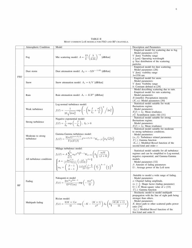
random variations of the refractive index due to fluctuations oftemperature and pressure in the atmosphere. Atmospheric tur-bulence affects FSO almost exclusively due to the wavelengthcompared to RF. Atmospheric turbulence can be modeled usingnumerical models based on Kolomogrov theory and statisticalmodels [24]. Different statistical models have been widely usedto model turbulent FSO channels in the literature, such as thenegative exponential, log-normal, Gamma-Gamma, and theMalaga models [11].Dynamic wind loads causing sway of buildings, weak earth-quakes, and small vibrations due to road traffic cause the beamto deviate from its path randomly [25]. These effects are knownas pointing errors and impose additional challenges for FSOlinks and severally affect the transmissions’ reliability if notcompensated. Pointing errors are commonly modeled using aRayleigh distribution [26]. In terms of noise, FSO is subjectto ambient noise from the sun, while RF is subject to thermalnoise.For a full budget link calculation of FSO links, taking intoaccount attenuation, turbulence, beam divergence, and pointingerrors, we direct the reader to the detailed study in [14].As takeaway messages of this section, the full comparisonbetween the FSO and RF technologies is summarized in Table I.Moreover, the most common line of sight (LoS) models forthe FSO and RF channels under different channel conditionsare reported in Table II.
III. MIXED RF/FSO MULTIHOP LINKS
A possible scenario for the deployment of FSO is when it iscombined with RF transmission systems to fill the connectivitygap between the RF access network and the fiber backbonenetwork [35], [36]. A schematic illustration of a dual-hopmixed RF/FSO configuration is shown in Fig. 4. The dual-hophas two primary designs: Amplify and Forward (AF) andDecode and Forward (DF).
• In an AF system, the data initially encoded on an RFchannel is received by an antenna at a relay node. Thereceived electrical signals are converted to optical signalsand amplified and forwarded to the FSO transmitter atthe relay.
• In the case of DF relaying, the signal is decoded,regenerated, and then retransmitted to the FSO node.
The AF approach is preferable and less complex than DF, asit does not require any decoding at the relay node.
Dual-hop heterogeneous systems, with both AF and DF
5
TABLE ICOMPARISON BETWEEN FSO AND RF TECHNOLOGIES.
Technology RF FSOAvailable Spectrum ∼ 300 GHz ∼ 100s THz
Licensing Licensed UnlicensedTerminal Foot-prints Bulk SmallEnergy Consumption Tens of [W] Tens of [mW]
Data Rates Mbits/Gbits TbitsConfiguration LoS/NLoS LoS
Latency Moderate LowNoise sources Interference with other users Background ambient light
Safety Subject to EMF radiations Eye and skin safeSecurity Susceptible to Eavesdropping Secure
Sensitivity to Pointing Errors Low HighPropagation Effects Attenuation, fading Attenuation, turbulence
relays, have been well studied considering a wide range ofRF and FSO channels [35]–[39]. In a seminal study, Lee et al.studied the outage performance of a dual-hop heterogeneousRF/FSO system with a fixed gain AF relay [35]. The RFlink is assumed to be subject to a Rayleigh fading, and theFSO is subject to Gamma-Gamma turbulence. A sub-intensitymodulation (SIM) scheme was considered for the AF relayto convert the incoming RF signal to optical signals beforebeing forwarded to the destination. We note that SIM is atechnique that consists of modulating a pre-modulated RFsignal on the intensity of optical signals, which lowers thesystem’s complexity [40]. The primary outcome of the studyreported in [35] is that RF/FSO systems have slightly worseperformance (in terms of outage probability) than conventionaldual-hop RF/RF links. The work was followed by the outageperformance analysis of a dual-hop system subject to a Rayleighfading for the RF hop and an M-fading generalized model forthe FSO hop [36]. The authors also assumed a SIM schemeto convert the RF signals to optical signals at the fixed-gainAF relay node and further considered the effect of pointingerrors that could occur on the FSO link. The capacity and errorperformances of a dual-hop RF/FSO system with a Nakagami-m RF channel and a Gamma-Gamma distributed FSO linkwere studied in [37]. Authors of [38] considered the same RFand FSO channel conditions as [35] but with a DF relayingscheme. Both fixed gain and channel state information (CSI)relaying scenarios are considered in a dual-hop RF/FSO studyreported in [39], where the RF link is subject to a Nakagami-mfading, and the FSO is subject to Gamma-Gamma turbulence.Note that the CSI-based relaying, also known as variable gain,assumes feedback sent from the receiver to the transmitter. Theeffect of outdated CSI on the outage BER performances ofRF/FSO mixed system was investigated in [41]. The authorsassumed that the RF link is subject to Rayleigh fading, andthe FSO is modeled by a Gamma-Gamma distribution.
A less conventional relaying scheme known as Quantize andEncode (QE) was considered in an RF/FSO dual-hop system[42]. In a QE relaying scheme, the RF source uses a quadratureamplitude modulation (QAM) format, and the relay estimatesand quantizes the log-likelihood ratio of each received bit in aQAM symbol and then transmits it through the FSO channel.Overall, with many relaying schemes, mixed RF/FSO systemshave been well studied in the literature.
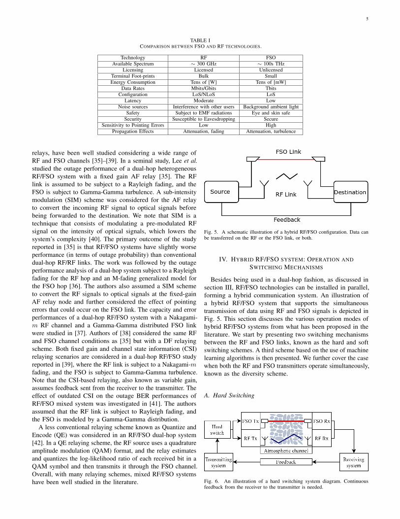
Fig. 5. A schematic illustration of a hybrid RF/FSO configuration. Data canbe transferred on the RF or the FSO link, or both.
IV. HYBRID RF/FSO SYSTEM: OPERATION ANDSWITCHING MECHANISMS
Besides being used in a dual-hop fashion, as discussed insection III, RF/FSO technologies can be installed in parallel,forming a hybrid communication system. An illustration ofa hybrid RF/FSO system that supports the simultaneoustransmission of data using RF and FSO signals is depicted inFig. 5. This section discusses the various operation modes ofhybrid RF/FSO systems from what has been proposed in theliterature. We start by presenting two switching mechanismsbetween the RF and FSO links, known as the hard and softswitching schemes. A third scheme based on the use of machinelearning algorithms is then presented. We further cover the casewhen both the RF and FSO transmitters operate simultaneously,known as the diversity scheme.
A. Hard Switching
Fig. 6. An illustration of a hard switching system diagram. Continuousfeedback from the receiver to the transmitter is needed.
6
TABLE IIMOST COMMON LOS MODELS FOR FSO AND RF CHANNELS.
Atmospheric Condition Model Description and Parameters
FSO
Fog Mie scattering model: A =13
V
(λ
0.55
)−q[dB/km]
· Empirical model for scattering due to fog.· Model parameters [27]:V [km]: Visibility rangeλ [µm]: Operating wavelengthq: Size distribution of the scatteringparticles
Dust storm Dust attenuation model: Ad = −52V −1.05 [dB/km]
· Empirical model for dust scattering.· Model parameters [28]:V [km]: visibility rangeλ=1550 nm
Snow Snow attenuation model: As = k/V [dB/km]
· Empirical model for snow.· Model parameters:V [km]: Visibility rangek: Constant defined in [29]
Rain Rain attenuation model: Ar = KRα [dB/km]
· Model describing scattering due to rain.· Empirical model for rain scattering.· Model parameters:R [mm/hr]: Precipitation intensity(K,α): Model parameters [30]
Weak turbulence
Log-normal turbulence model:
f(I) =1
2I√
2πσ2I
exp
−(lnI
Io+σ2I
2
)2/2σ2I
· Statistical model suitable for weakfluctuations regime.· Model parameters:E[I] = I0: Mean irradiance.σ2I : Scintillation index (SI) [31]
Strong turbulenceNegative exponential model:
f(I) =1
I0exp
(−I
I0
), I0 > 0
· Statistical model suitable for strongfluctuations regime.· Model parameters:E[I] = I0: Mean irradiance
Moderate to strongturbulence
Gamma-Gamma turbulence model:
fI(I) =2(αβ)(α+β)/2
Γ(α)Γ(β)I(α+β)/2−1Kα−β
(2√αβI
)· Statistical model suitable for moderateto strong turbulence conditions.· Model parameters:(α, β): Turbulence related parameters·Γ(.): Gamma function·Kv(.): Modified Bessel function of thesecond kind and order v
All turbulence conditions
Malaga turbulence model:
fI(I) = A
β∑k=1
αkIα+k
2−1Kα−k
(2
√αβI
γβ + Ω
)A = 2αα/2
γ1+α/2Γ(α)
(γβ
γβ+Ω
)β+α2
αk =
(β − 1
k − 1
)(γβ+Ω
′)1− k
2
(k−1)!
(Ω′
γ
)k−1 (αβ
) k2
· Statistical model suitable for all turbulenceregimes and can be simplified to Log-normal,negative exponential, and Gamma-Gammamodels· Model parameters [32]β: Amount of fading parametersΩ : Average power of the LoS term
RF
FadingNakagami-m model
f(x) =2mmx2m−1
ΩmΓ(m)exp(−mx2
Ω
) ·Suitable to model a wide range of fading.· Model parameters:x: Channel fading amplitude,m ≥ 1
2: Shape factor (fading parameter)
Ω > 0: Mean-square value of x [33]·Γ(.): Gamma function
Multipath fading
Rician model:
f(x) =2(K + 1)x
Ωexp
(−K −
(K + 1)
x2
)I0
(2
√K(K + 1)
Ωx
)· Stochastic model to model multipathpropagation with the line of sight path beingstronger than others.· Model parameters:K direct path to other scattered paths powerratio [34]·I0(.): Modified Bessel function of thefirst kind and order 0

7
In a system based on hard switching, either the RF link orthe FSO link is operational at any given time. Feedback fromthe receiver to the transmitter is used to coordinate betweenthe two communicating terminals to perform the switching.Usman et al. proposed in [43] a hard switching mechanism forhybrid FSO/RF systems. The authors assumed the use of theFSO link when it is above a certain threshold, and when thelink becomes unacceptable, the RF is used instead. A dual FSOthreshold system design was also considered, where the FSOhas two different thresholds for transitioning between “on” and“off” states. The dual threshold system showed to be similarin performance to a simple hard switching while reducingthe number of switches and preserving the FSO subsystem.The performance of the hard-switching approach was furtherinvestigated in numerous manuscripts [44], [45]. Authors of[44] studied the performance of a hard-switch-based RF/FSOsystem over generalized fading models. Time Hysteresis (TH)and Power Hysteresis (PH) modifications to the hard-switchingapproach were studied in [45], where the switching thresholdmay be variable based on the channel conditions and history.A multi-user FSO/RF hybrid network scheme was proposed in[46], where a primary FSO link services every user. When theFSO link fails, a central node allocates a backup RF link withnon-equal priority to different users. Finally, the performanceof a selective dual-hop RF/FSO DF relay network based onhard switching was studied in [47]. The authors assumed twoRF/FSO subsystems with a relay node and maximum ratiocombining (MRC) scheme at the receiver [47]. The proposedscheme was found to outperform FSO cooperative system andsingle hope RF/FSO system.
B. Soft Switching
Fig. 7. An illustration of a soft switching system diagram based on jointencoding and decoding and with an optional (that is limited if used) feedbackfrom the receiver to the transmitter.
Within the soft-switching approach, channel coding can beused to coordinate between the FSO and the RF links. Themain advantage of the soft-switching compared to the hard-switching is that the rate of the FSO link is not wasted if theRF link is selected. Zhang et al. proposed a soft switchingapproach based on short length Raptor codes [48]. In Raptorcodes, each message sent from the RF and FSO subsystemsis different from the previous one. The decoder decides toaccept the entire block as soon as a sufficient number ofmessages have been collected, whether they come from RF orthe FSO transmitter. This approach allows utilizing an otherwiseunused FSO data rate for long-distance transmission scenarioswhen the received FSO power would be considered below the
threshold for the hard switching-based mechanism. Authors of[48] showed a rate gain by 4 folds (and more) compared to thehard switching approach for 1 and 2 km transmission lengthscenarios. However, both hard- and soft switching approachesshowed similar average data rate performance at a half-kmtransmission length due to the sufficient optical power at thereceiver.Alternatively, authors of [49] proposed to adapt the transmittedsymbol rate and the constellations on the RF and FSO linksdepending on the channel conditions. The authors pointed thatsuch an approach could be particularly of interest for grid-connected systems, where power conservation is not crucial.
C. Machine Learning Based Switching
Fig. 8. An illustration of an ML-powered system diagram where hard switchingis performed based on the ML prediction. The feedback in the ML scheme isoptional.
Machine learning is a versatile tool that has found usesin almost all the various fields of communication. Machinelearning has been used in RF and optical communicationsystems for applications such as performance monitoring,modulation format identification, channel modeling, and digitalsignal processing [50]–[52]. However, for the hybrid FSO/RFsystems, only a few studies have been so far reported. In[53] and [54], several machine learning algorithms, includingrandom forest, decision tree, and others, are exploited topredict the received signal strength indicator (RSSI) in ahybrid FSO/RF hard switching system. Accurate predictionof RSSI parameter helps in fastening the switching betweenFSO link and RF link where for low RSSI, low-speed RFlink is used and for high RSSI, high-speed FSO link is used.The obtained results show high accuracy for predicting theRSSI parameter with superiority for the decision tree algorithm.Proactive switching for hybrid FSO/RF links that ensure energyefficiency is studied in [55]. In hybrid FSO/RF links, energywastage happens because of the need to continuously keep theFSO link “on” when the RF link is operational. The reason is tomonitor the channel, so when the channel conditions improve,the system switches to the FSO link. To cope with this problem,the authors of [55] proposed that when the RF link is “on”, theFSO link is kept in sleep mode with the capability to activateit periodically to sample the FSO signal power by transmittingbeacon signals. These samples are used to train a Long ShortTerm Memory (LSTM) algorithm to predict the link switchingtime (the time when the FSO signal is expected to be above apredetermined threshold). The reported simulation results haveshown that the proposed technique can significantly improvethe energy efficiency of the RF/FSO system [55].

8
D. Diversity Scheme
Fig. 9. An illustration of a diversity system diagram where both systemssimultaneously and the received data from the RF and FSO link are combinedin a combiner unit. The feedback in the diversity scheme is optional.
The diversity scheme consists of simultaneously transmittingthe same information on FSO and RF co-existing links. Underthe assumption that millimeter waves at 6 GHz support thesame data rates as optical links, authors of [56] proposedencoding the same data signals on an FSO and an RF link.At the receiver, selective combining (SC) and MRC schemesare considered. This diversity approach is challenging mainlywhen a complex modulation format, such as phase shift keying(PSK), is used with the optical links requiring coherent systems.
Authors of [57] proposed the use of receive diversity in ahybrid setup by introducing multiple receivers for both FSOand RF subsystems. The FSO link is assumed to have an equalgain combining (EGC) scheme, while the RF had an MRCscheme to collect received signals. An IM/DD configurationwas considered for the FSO, making the implementation of sucha system possible in practice. The proposed hybrid RF/FSOsystem design demonstrated reduced power consumption for asimilar performance compared with RF or FSO only solutionsand the case when only a single receiver RF/FSO system isused. The primary motivation of the proposed technique is tobe used in scenarios where one of two links experiences afrequent outage due to the weather conditions.Rakia et al. proposed a power adaptation scheme based ontruncated channel inversion for an FSO/RF system employingadaptive combining to ensure a constant signal-to-noise ratio(SNR) [58]. The FSO transmitting power was considered tobe constant, and two policies of power allocation to the RFsubsystem, based on RF only and joined SNR, were considered.Unlike other diversity schemes presented, the feedback channelbetween receiver and transmitter is once again needed in thisscheme.
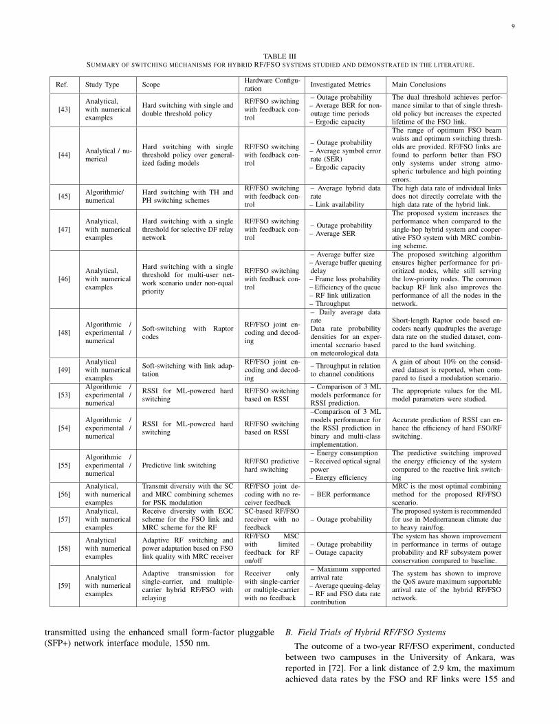
Finally, a complex hybrid RF/FSO backhaul network wasconsidered in [59]. The authors proposed the use of buffer-aidedand quality-of-service (QoS) aware relays in conjunction withnovel adaptive single-carrier and multiple carrier transmissionschemes to reduce delay for latency-sensitive applications suchas virtual reality and smart grid control. Given a fixed QoS,numerical simulations showed an increase in the maximumsupported arrival rate.A detailed summary of the studies on the various RF/FSOswitching mechanisms in the literature is given in Table III.
V. RF/FSO SYSTEMS HARDWARE CONFIGURATION
In this section, we discuss the hardware configuration forpractical hybrid RF/FSO systems. In particular, we reviewthe specification of commercially available RF/FSO solutions.Then, we present some of the recent field trials aiming to setreliable RF/FSO systems.
A. Commercially Available RF/FSO Solutions
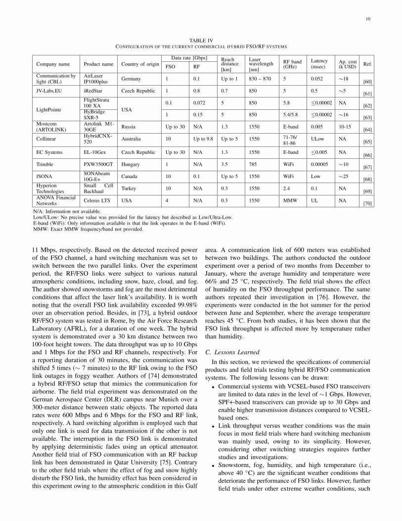
Recent market statistics have shown that the expectedinvestments in FSO equipment will exceed $300 million in 2029[71]. There are many commercially available FSO products,and some of these systems offer the possibility to also transmitdata over RF channels [64]. In this section, we highlight themain features of some of the currently available FSO/RFsolutions. Table IV summarizes the main configurations ofcommercially available products in terms of data rate, reachdistance, operating wavelength, backup RF band, latency, andthe approximate cost (whenever the information is available).Note that the system’s approximate cost varies with thecustomization and how big the equipment order is.
Some hybrid commercial products offer FSO links that cansupport up to 30 Gbps in ideal weather conditions, such as ECSystems (EL-10Gex) and Mostcom (Artolink M1-30GE). Themaximum transmission distance can also reach up to 5 km withCollinear (HybridCNX-520) and fSONA (SONAbeam 10G-E+)solutions. However, in harsh environments (under heavy fog,dust, or snow), the communication link is often switched to theRF backup channel. The data rates are reduced by more than anorder of magnitude, as specified by Communication by Light(CBL-AirLaserIP1000plus), LightPointe (HyBridge SXR-5),and fSONA (SONAbeam 10G-E+) systems. Note that mostcompanies have used unlicensed RF bands for the radio backuplinks to reduce interference and cost. These bands include bothlower frequency sub-bands (typically 2.4 and 5 GHz) andhigher frequency millimeter-wave (MMW) sub-bands beyond60 GHz.
Latency is a crucial parameter in emerging and next-generation wireless networks. For instance, the 5G New Radio(NR) global standard is targeting 1 msec as air-interface latency.In this regard, current commercial products have shown FSOlinks latency varying from 0.1 msec (Hyperion Technologies)to 50 nsec (Trimble) with transmission distances ranging from0.3 to 3.5 km, respectively. This motivates the deployment ofthese systems in advanced wireless communication networks.Furthermore, the current commercial solutions operate in the850 nm and 1550 nm bands. Both bands are characterized bylow atmospheric attenuation. Besides being “eye-safe”, one ofthe advantages of the 1550 nm band is the relatively low costof FSO transmitting and receiving devices. Advanced vertical-cavity surface-emitting laser (VCSEL) transmitters and highsensitive avalanche photodiodes (APD) are widely used in thisband. The proliferation of high-speed transmitters, amplifiers,wavelength division multiplexing (WDM) components, andreceivers optimize the FSO transmission in the 1550 nm band.It is worth noting that the maximum commercial speed in the850 nm band is 1 Gbps using VCSELs and on-off keying(OOK) modulation, whereas beyond 10 Gbps (OOK) can be
9
TABLE IIISUMMARY OF SWITCHING MECHANISMS FOR HYBRID RF/FSO SYSTEMS STUDIED AND DEMONSTRATED IN THE LITERATURE.
Ref. Study Type Scope Hardware Configu-ration Investigated Metrics Main Conclusions
[43]Analytical,with numericalexamples
Hard switching with single anddouble threshold policy
RF/FSO switchingwith feedback con-trol
– Outage probability– Average BER for non-outage time periods– Ergodic capacity
The dual threshold achieves perfor-mance similar to that of single thresh-old policy but increases the expectedlifetime of the FSO link.
[44] Analytical / nu-merical
Hard switching with singlethreshold policy over general-ized fading models
RF/FSO switchingwith feedback con-trol
– Outage probability– Average symbol errorrate (SER)– Ergodic capacity
The range of optimum FSO beamwaists and optimum switching thresh-olds are provided. RF/FSO links arefound to perform better than FSOonly systems under strong atmo-spheric turbulence and high pointingerrors.
[45] Algorithmic/numerical
Hard switching with TH andPH switching schemes
RF/FSO switchingwith feedback con-trol
– Average hybrid datarate– Link availability
The high data rate of individual linksdoes not directly correlate with thehigh data rate of the hybrid link.
[47]Analytical,with numericalexamples
Hard switching with a singlethreshold for selective DF relaynetwork
RF/FSO switchingwith feedback con-trol
– Outage probability– Average SER
The proposed system increases theperformance when compared to thesingle-hop hybrid system and cooper-ative FSO system with MRC combin-ing scheme.
[46]Analytical,with numericalexamples
Hard switching with a singlethreshold for multi-user net-work scenario under non-equalpriority
RF/FSO switchingwith feedback con-trol
– Average buffer size– Average buffer queuingdelay– Frame loss probability– Efficiency of the queue– RF link utilization– Throughput
The proposed switching algorithmensures higher performance for pri-oritized nodes, while still servingthe low-priority nodes. The commonbackup RF link also improves theperformance of all the nodes in thenetwork.
[48]Algorithmic /experimental /numerical
Soft-switching with Raptorcodes
RF/FSO joint en-coding and decod-ing
– Daily average datarateData rate probabilitydensities for an exper-imental scenario basedon meteorological data
Short-length Raptor code based en-coders nearly quadruples the averagedata rate on the studied dataset, com-pared to the hard switching.
[49]Analyticalwith numericalexamples
Soft-switching with link adap-tation
RF/FSO joint en-coding and decod-ing
– Throughput in relationto channel conditions
A gain of about 10% on the consid-ered dataset is reported, when com-pared to fixed a modulation scenario.
[53]Algorithmic /experimental /numerical
RSSI for ML-powered hardswitching
RF/FSO switchingbased on RSSI
– Comparison of 3 MLmodels performance forRSSI prediction.
The appropriate values for the MLmodel parameters were studied.
[54]Algorithmic /experimental /numerical
RSSI for ML-powered hardswitching
RF/FSO switchingbased on RSSI
–Comparison of 3 MLmodels performance forthe RSSI prediction inbinary and multi-classimplementation.
Accurate prediction of RSSI can en-hance the efficiency of hard FSO/RFswitching.
[55]Algorithmic /experimental /numerical
Predictive link switching RF/FSO predictivehard switching
– Energy consumption– Received optical signalpower– Energy efficiency
The predictive switching improvedthe energy efficiency of the systemcompared to the reactive link switch-ing
[56]Analytical,with numericalexamples
Transmit diversity with the SCand MRC combining schemesfor PSK modulation
RF/FSO joint de-coding with no re-ceiver feedback
– BER performanceMRC is the most optimal combiningmethod for the proposed RF/FSOscenario.
[57]Analytical,with numericalexamples
Receive diversity with EGCscheme for the FSO link andMRC scheme for the RF
SC-based RF/FSOreceiver with nofeedback
– Outage probabilityThe proposed system is recommendedfor use in Mediterranean climate dueto heavy rain/fog.
[58]Analyticalwith numericalexamples
Adaptive RF switching andpower adaptation based on FSOlink quality with MRC receiver
RF/FSO MSCwith limitedfeedback for RFon/off
– Outage probability– Outage capacity
The system has shown improvementin performance in terms of outageprobability and RF subsystem powerconservation compared to baseline.
[59]Analyticalwith numericalexamples
Adaptive transmission forsingle-carrier, and multiple-carrier hybrid RF/FSO withrelaying
Receiver onlywith single-carrieror multiple-carrierwith no feedback
– Maximum supportedarrival rate– Average queuing-delay– RF and FSO data ratecontribution
The system has shown to improvethe QoS aware maximum supportablearrival rate of the hybrid RF/FSOnetwork.
transmitted using the enhanced small form-factor pluggable(SFP+) network interface module, 1550 nm.
B. Field Trials of Hybrid RF/FSO Systems
The outcome of a two-year RF/FSO experiment, conductedbetween two campuses in the University of Ankara, wasreported in [72]. For a link distance of 2.9 km, the maximumachieved data rates by the FSO and RF links were 155 and
10
TABLE IVCONFIGURATION OF THE CURRENT COMMERCIAL HYBRID FSO/RF SYSTEMS
Company name Product name Country of originData rate [Gbps] Reach Laser RF band Latency Ap. cost Ref.FSO RF distance
[km]wavelength[nm] (GHz) (msec) (k USD)
Communication bylight (CBL)
AirLaserIP1000plus Germany 1 0.1 Up to 1 830 – 870 5 0.052 ∼18 [60]
JV-Labs.EU iRedStar Czech Republic 1 0.8 0.7 850 5 0.5 ∼5 [61]
LightPointe
FlightStrata100 XA
USA0.1 0.072 5 850 5.8 ≤0.00002 NA [62]
HyBridgeSXR-5 1 0.15 5 850 5.4/5.8 ≤0.00002 ∼16 [63]
Mostcom(ARTOLINK)
Artolink M1-30GE Russia Up to 30 N/A 1.3 1550 E-band 0.005 10-15 [64]
Collinear HybridCNX-520 Australia 10 Up to 9.8 Up to 5 1550 71-76/
81-86ULow NA [65]
EC Systems EL-10Gex Czech Republic Up to 30 N/A 1.3 1550 E-band ≤0.005 NA [66]
Trimble PXW3500GT Hungary 1 N/A 3.5 785 WiFi 0.00005 ∼10 [67]
fSONA SONAbeam10G-E+ Canada 10 0.1 Up to 5 1550 WiFi Low ∼25 [68]
HyperionTechnologies
Small CellBackhaul Turkey 10 N/A 0.3 1550 2.4 0.1 NA [69]
ANOVA FinancialNetworks Celeras LTS USA 4 N/A 0.3 1550 MMW UL NA [70]
N/A: Information not available.Low/ULow: No precise value was provided for the latency but described as Low/Ultra-Low.E-band (WiFi): Only information available is that the link operates in the E-band (WiFi).MMW: Exact MMW frequency/band not provided.
11 Mbps, respectively. Based on the detected received powerof the FSO channel, a hard switching mechanism was set toswitch between the two parallel links. Over the experimentperiod, the RF/FSO links were subject to various naturalatmospheric conditions, including snow, haze, cloud, and fog.The author showed snowstorms and fog are the most detrimentalconditions that affect the laser link’s availability. It is worthnoting that the overall FSO link availability exceeded 99.98%over an observation period. Besides, in [73], a hybrid outdoorRF/FSO system was tested in Rome, by the Air Force ResearchLaboratory (AFRL), for a duration of one week. The hybridsystem is demonstrated over a 30 km distance between two100-foot height towers. The data throughput was up to 10 Gbpsand 1 Mbps for the FSO and RF channels, respectively. Fora reporting duration of 30 minutes, the communication wasshifted 5 times (∼ 7 minutes) to the RF link owing to the FSOlink outages in foggy weather. Authors of [74] demonstrateda hybrid RF/FSO setup that mimics the communication forairborne. The field trial experiment was demonstrated on theGerman Aerospace Center (DLR) campus near Munich over a300-meter distance between static objects. The reported datarates were 600 Mbps and 6 Mbps for the FSO and RF link,respectively. A hard switching algorithm is employed such thatonly one link is used for data transmission if the other is notavailable. The interruption in the FSO link is demonstratedby applying deterministic fades using an optical attenuator.Another field trial of FSO communication with an RF backuplink has been demonstrated in Qatar University [75]. Contraryto the other field trials where the effect of fog and snow highlydisturb the FSO link, the humidity effect has been considered inthis experiment owing to the atmospheric condition in this Gulf
area. A communication link of 600 meters was establishedbetween two buildings. The authors conducted the outdoorexperiment over a period of two months from December toJanuary, where the average humidity and temperature were66% and 25 C, respectively. The field trial shows the effectof humidity on the FSO throughput performance. The sameauthors repeated their investigation in [76]. However, theexperiments were conducted in the hot summer for the periodbetween June and September, where the average temperaturereaches 45 C. From both studies, it has been shown that theFSO link throughput is affected more by temperature ratherthan humidity.
C. Lessons LearnedIn this section, we reviewed the specifications of commercial
products and field trials testing hybrid RF/FSO communicationsystems. The following lessons can be drawn:
• Commercial systems with VCSEL-based FSO transceiversare limited to data rates in the level of ∼1 Gbps. However,SPF+-based transceivers can provide up to 30 Gbps andenable higher transmission distances compared to VCSEL-based ones.
• Link throughput versus weather conditions was the mainfocus in most field trials where hard switching mechanismwas mainly used, owing to its simplicity. However,considering other switching strategies requires furtherstudies and investigations.
• Snowstorm, fog, humidity, and high temperature (i.e.,above 40 C) are the significant weather conditions thatdeteriorate the performance of FSO links. However, furtherfield trials under other extreme weather conditions, such
11
as rain and dust storms, are required before large-scaletechnology deployment.
VI. RF/FSO FOR SPACE COMMUNICATIONS
Here, we discuss the potentials of the co-existence of RF andFSO technologies for near-Earth and deep space applications.
A. Overview on Satellites and Space Communication
Satellites have a wide range of applications, includingremote sensing, climate change control, deep space exploration,tackling the digital divide, and providing connectivity torural areas [77]. There are three main types of Earth orbitssatellites:
• Low Earth Orbit (LEO) Satellites: which operate in closeproximity of Earth over distances between 160 to 2000km. LEO satellites are mainly used for imaging and areknown for the low latency due to the relatively shortpropagation distance in space. Recently, LEO satelliteconstellations (a group of satellites working together) arereceiving considerable attention and being used to provideconnectivity in rural areas.
• Medium Earth Orbit (MEO) Satellites: which operate inthe region above 2000 km and below the static geostation-ary orbit. MEO satellites are mainly used for navigation,communication, and space environment science.
• Geosynchronous Earth Orbit (GEO) satellites: which arefixed with Earth in the geostationary orbit (35,786 km)above the Earth’s equator and rotate in the same directionwith the Earth’s rotation. GEO satellites are typicallyused for TV broadcasting and used by some satellitecommunication companies to provide world coverage witha minimum number of satellites.
In satellite communication, the link connecting the networkto the satellite is known as a feeder link. The satellite sendssignals to ground users through multi-beams, known as theuser links.
Traditional satellite communication has been historicallybased on microwave bands, in particular, the L (1-2 GHz), Ku-band (12-18 GHz), and the Ka-band (26.4-40 GHz). Comparedto the Ku and Ka bands, the L band is less susceptible tofading caused by rain. Ka and Ku have wider bandwidths andsmaller components. In the Ku band, only 1 GHz of bandwidthis allocated for satellite services: half of it for uplink and theother half for the downlink. 6 GHz of bandwidth is dedicatedin the Ka-band for satellite communication [78].
B. Optical Near-Earth Space Communication
Optical communication in space has made tremendousprogress over the years [79]. An early inter-satellitedemonstration has reported a successful error-free 5.6 Gbpstransmission between two Low Earth Orbit (LEO) satellites(NFIRE and TerraSar-X) over several seconds [80], [81].Ground-to-satellite (uplink) and satellite-to-ground (downlink)FSO links have also been demonstrated [82], [83]. Thefirst uplink and downlink demonstrations date back to 1994
with a 1.024 Mbps two-way communication between theJapanese Engineering Test Satellite-VI (ETS-VI) and a groundstation [82]. In 2016, the SOTA (Small Optical TrAnsponder)system, developed by the National Institute of Informationand Communications Technology (NICT) in Japan, was usedto establish an optical communication link between a LEOsatellite (SOCRATES) to ground connection with a groundstation affiliated to the German aerospace center [83]. NASA,in collaboration with MIT Lincoln Laboratory, is currentlydeveloping a 200 Gbps optical communication system to beinstalled on an LEO Cubesat (small satellite at an altitude of740 km) with a downlink that could reach 200 Gbps to delivermore than 50 Terabytes of information per day to a groundstation, as a part of the TeraByte InfraRed Delivery (TBIRD)program [84]. In addition to the vast bandwidth, opticalsatellite link require small footprints devices that consume lessenergy compared to those operating in the microwave bandstypically used for Earth-satellite communications.
As the satellite communication race gears up, multiplecompanies are developing optical free space feeder links andinter-satellite links to bring fiber-like throughput to space. Forexample, Lightspeed-Telesat, and Starlink-SpaceX projectsaim to establish FSO satellite crosslinks in their satelliteconstellations installed to provide broadband internet accessall over the globe [85], [86].
Optical links are preferable compared to RF links for spaceapplications because of the lower divergence of optical wavesthan the RF ones. However, ground-space optical links aresubject to turbulence and weather conditions, particularly inthe lower layers of the atmosphere, as discussed in section II-D.
C. Mixing Optical and RF Links For Satellite Communication
Mixing optical communications and RF can be highlyadvantageous in applications related to satellite, and deep-spacecommunications [13]. As we pointed out earlier, optical linksare subject to atmospheric turbulence affecting earth-to-spaceand space-to-earth links. Even though RF and optical beamsmay propagate through the same geometrical path through theatmosphere, the channel effects, in most cases, are more severeon optical signals. These effects are caused by the variousair densities on different heights above the ground and thedifference in the air’s turbulent behavior closer to the ground.The distortions of the beam attributed to the atmosphericturbulence are far greater close to the ground due to moresubstantial turbulence and higher air density. This means thatthe downlink beam will encounter most of the disturbancescloser to the receiver, resulting in fewer distortions on thebeams’ intensity profiles than in the uplink case, where mostof the atmospheric disturbances are encountered immediatelyafter leaving the transmitter, and its adverse diffractive effectscan accumulate over longer propagation distances.Therefore, it may be beneficial for the hybrid RF/FSO systemto use FSO for downlink and RF for the uplink. This isalso beneficial, as RF downlink signals may contribute tothe spectrum congestion on the ground due to its large spotsize. We note that RF signals can result in interference for
12
the uplink but not as prominent as the downlink case. FSOcan be further beneficial for the downlink from the energyefficiency standpoint due to the reduced energy consumption[87], [88]. However, more efforts are required to developadvanced pointing, acquisition, and tracking mechanisms (PAT)for FSO systems for near-Earth application [89]–[92].We note that many satellite and aerial network configurationsbased on hybrid RF/FSO links have been proposed in theliterature, such as the following:
1) Satellite-aerial-terrestrial network, where a high-altitudeplatform (HAP) acts as a relay between a satellite andterrestrial terminals [93]–[96].
2) Spatial networks, where the communications links suchas satellite-to-satellite (in the same or different orbits),HAP-to-HAP. The links in these layers can be establishedusing both RF or FSO [97].
3) Hybrid networks as the RF link is for the ground-to-airchannel, and the FSO link is for the air-to-air path, anda hybrid RF/FSO system for the air-to-ground channel.Such a setup utilizes the frequency spectrum efficiently,enhances data rates, and provides inherent security [98].
4) Multibeam high-throughput satellite systems where thefeeder link operates in the FSO band and the user link,between the satellite and the user terminal, is in the RFKa-band [99].
Another potential application of using FSO together withRF systems that worth mentioning in this section is achievingsatellite-based quantum key distribution (QKD). Satellite-basedQKD consists of distributing secret encryption keys to enhancethe security of long-range communication systems. Earth-Satellite QKD demonstrations over distances beyond 1000 kmhave been reported [100], [101]. The field of satellite-basedQKD is continuously growing [102], [103], and these researchand development efforts will result in a global QKD networkthat may enhance the encryption of conventional near-Earthcommunication.
D. RF/FSO for Deep Space Operations
For deep space communication, RF can benefit from thewell-established infrastructure of the current systems. FSO canbe used as a complementary technology to push the data ratesfor this infrastructure, opening the door to various applicationssuch as outer-space real-time video streaming and the transferof high-resolution images. Indeed, recent demonstrations haveshown that optical wireless communication can potentiallybring fiber-like connectivity to the space [104], [105]. InFall 2013, Nasa’s Lunar laser communication demonstration(LLCD), which was part of the LADEE (Lunar Atmosphereand Dust Environment Explorer) mission, reported a seriesof full-duplex communications between a satellite in lunarorbit (400.000 from the Earth) and multiple ground stations(in Spain and US) with a maximum uplink throughput of 20Mbits and downlink throughput of 622 Mbits [104], [105]. Incollaboration with SpaceX company, NASA is also currentlyworking to install an FSO system for the Psyche mission toexplore a metal asteroid orbiting between March and Jupiter[106]. The idea is to improve communication performance
by 10 to 100 times over the current RF technology withoutincurring increases in mass, volume, or power. The FSO linkis expected to be operational in 2026.
VII. OPEN ISSUES AND FUTURE RESEARCH DIRECTIONS
In the following, we discuss the open issues associatedwith the RF/FSO co-existence, related mainly to the cost oftechnology deployment. We then provide a set of future andinsightful research directions that we believe can potentiallylead to the wide-scale deployment of parallel RF/FSO links.
A. Economic ChallengesThe main limiting factor of the wide-scale deployment of
RF/FSO is the cost. The cost of building the optical wirelessinfrastructure by network operators is a significant challenge,in particular when coherent detection is used or sophisticatedPAT systems are involved for the FSO links. However, thereturn of investment in terrestrial applications can be quick,mainly if IM/DD systems are installed, and the FSO systemis the primary link to preserve the power consumption. Thecost may also vary depending on the installation’s geographicallocation. For example, suppose the hybrid system is installedin a site where fog is a dominant weather condition. In thatcase, it will mostly rely on radio technology, which deriveshigher Operating expenses (OPEX). Programming the devicesto perform the switching mechanisms can also generate extracosts. To build confidence in such a technology, it should beinstalled in pilot locations such as cities with clear weatherconditions throughout the year.
B. Boosting the Role of Machine LearningUsing machine learning algorithms for efficient switching
between FSO and RF links has not yet been fully exploited.Efficient switching ML-based algorithms can be built based onseveral parameters like channel impairments. Such parameterscould be predicted using various ML tools with high accuracy,as reported in [107]–[109]. A recent study reported in [109],has shown that turbulence, pointing errors, and optical SNRcan be predicted accurately at different FSO transfer rates. ML-based switching can also be set on power consumption or othernon-channel-related parameters such as the EMF radiation.This scenario can be suitable for cases when the RF is theprimary source of communication. The FSO system, in thiscase, can be turned “on” to reduce the amount (or duration)of EMF radiations in a particular location.
We should note that the adoption of ML algorithms in parallellinks requires channel measurements on various RF and FSOchannel conditions to build the learning models. The relativelynewly introduced Generative Adversarial Networks (GAN) MLframework can be used for data augmentation in such cases. Wenote that GAN is a deep neural network that learns to generatenew data with the same statistics of the learning set [110].Using GAN can minimize the amount of outdoor collecteddata required to train the learning models for the RF/FSOML-based switching method; in particular, that measurementcollection can be a time-consuming process. A recent studyrevealed that GAN-based modeling is promising in wirelessRF communication [111].
13
C. Connecting the Unconnected
As of January 2021, more than 35% of the world populationdoes not have access to the internet [112]. A large percentageof the connected population is also under-connected withlimited access to the internet, even in developed countries.RF/FSO hybrid backhauling can significantly contribute toconnecting the unconnected and under-connected world regions.Setting new optical fiber networks can be costly, mainly interms of Capital Expenditure (CAPEX), which involves theinitial installation cost [113]. OPEX of RF/FSO systems iscomparable to those of RF-only systems, especially if theFSO link is operational over long hours, which reduces theoverall energy consumption. Using only RF links may alsonot be enough to fulfill the continuously increasing capacitydemand. Therefore, co-installing RF and FSO technologies canbe a practical solution yet economically profitable to connectfar-flung areas with higher resistance to natural disasters.In particular, commercially available plug-and-play hybridsystems can cover distances up to 10 km and can be installedquickly without incurring civil engineering costs to lay opticalfibers underground [14]. RF/FSO system can equally contributeto enhancing the internet throughput for those living in denselypopulated areas and suffering from low internet penetration.Providing reliable connectivity to these locations can enablenew technologies for smart agriculture and also climate changemonitoring and internet of things (IoT) devices [114].
D. Massive MIMO Hybrid RF/FSO
Massive MIMO configuration can significantly contributeto increasing the data rates of radio links [115]. A massiveMIMO configuration can enable to match the throughputof RF links to what could be provided by a single FSOlink. Progress in VCSEL technology has also led to thedevelopment of many FSO sources that could be modulatedindependently on a single chip. There are also various designsof multi-aperture detectors in direct and coherent detectionconfigurations. Newly developed antennas can be incorporatedto extend the field of view of high-speed optical detectors[116]. MIMO RF/FSO can equally improve the reliability ofboth links.
E. Non-Conventional RF/FSO hybrid systems
There has been considerable interest in using the orbitalangular momentum (OAM) degree of freedom of theelectromagnetic wave to push the transmission capacity [117].OAM is associated with a helical phase- front of exp(i`φ)[118], with ` being the topological charge and φ is theazimuth. The orthogonality between OAM beams enabledan extra multiplexing scheme in optical communication[119]. OAM multiplexing is possible in FSO, as well asin radio communication [120]. Beyond Tbps transmissionswere reported using OAM multiplexing using optical signalspropagating in free space [121], [122] and Multi-Gbpstransmissions have also been demonstrated in the RF domain[123]. OAM multiplexing is a particular case of spatial
mode multiplexing, which also involves using orthogonalmode families to carry independent data streams, such asthe Laguerre Gaussian (LG), Hermite Gaussian (HG), andInce Gaussian (IG) mode bases. Another promising aspect ofusing spatial mode multiplexing is fulfilling diversity withoutany requirements on the separation between the transmittingor receiving apertures [124]. Diversity is not restricted toOAM-only modes derived from LG mode basis but can covermodes from different mode bases, such as LG and HG modes.Djordjevic proposed in [125] using OAM FSO/RF to increasethe spectral efficiency and PLS of the optical and RF wirelesssystems [125].
This non-conventional RF/FSO spatial-mode based isindeed promising. However, there are still some issues mainlyassociated with the design of compact mode generationand detection techniques that need to be addressed beforedeploying such a method beyond laboratory-test benches eitherin the optical or RF bands.
F. Toward Multiband Transmission
The THz band has recently attracted considerable attentionand seems to offer plenty of opportunities for wireless commu-nication [126]. Progress in devices and modeling may bringTHz communication to life sooner than we thought [127], [128].Incorporating this frequency band, ranging from 100 GHz to 10THz, fills the gap between the RF and optical bands and leadsto creating multiband systems. Multiband systems can providefurther resilience to a wide range of channel conditions [129].For example, as we discussed in section II-D, FSO signalsare severely affected by dust storms. However, experimentalinvestigations, reported in [129], showed that THz signals arebarely affected by dust signals. Multiband can equally openup new applications. Although water vapor in the atmosphereseverely absorbs THz signals, they can be used with RF/FSOsystems to provide high-throughput connectivity in non-line-of-sight scenarios or short-range transmissions.
Multiband transmission can be further of interest for near-Earth and deep space applications. THz beams have lowerdivergence compared to RF ones, which can provide a goodcompromise between pointing sensitivity and geometrical loss.It has been pointed out that THz communication systems canoffer a comparable performance to FSO systems for Earth-to-satellite links in dry regions [130].
Another advantage of parallel multiband transmissions isstrengthening the secrecy of the system. If an intruder isdetected in one band, switching the communication on oneof the other two technologies makes signal interception orjamming difficult. It is also possible to divide the sameinformation on the various communication bands, restrictingany eavesdropper from revealing any useful information byeavesdropping on a single band. This can provide extra securityto RF/FSO networks.
G. Toward Self-Powered RF/FSO Networks
Solar-powered RF base stations are being deployed invarious areas of the world [131]. Powering RF sites using solar

14
panels can ensure power delivery to radio base stations inremote locations or regions without reliable grid connectivity[131]. A future idea to explore is to build hybrid RF/FSOself-powered networks. A particular scenario of interestis to use FSO systems to lower power consumption inbattery-powered sites to avoid or reduce the power outageperiod, mainly because FSO systems typically consume lessenergy than the RF ones, and therefore ensuring longer batterylives.
Using solar power as an energy source can reduce the carbonfootprints of cellular base stations compared to fuel-poweredones. It has also been demonstrated that off-the-shelf solarpanels can be used to decode information signals whileharvesting energy [132]. Indeed, high data rates in the orderof 1 Gbps can be reached when using solar cells operating asphotodetectors [133]. MIMO configuration using solar cellshas been shown to be also possible in [134]. Using solar cellsinitially used to power base station batteries to decode opticalinformation signals without using any dedicated photodetectorsis another idea to explore, mainly in scenarios when no largeamount of data is transmitted. Using large area solar detectorscan equally ease the PAT requirements for FSO systems even inthe presence of atmospheric turbulence or slight pointing errors.
VIII. CONCLUSION
FSO communication is paving the way toward high-speedwireless backhauls. However, the sensitivity of optical signalsto atmospheric turbulence may limit the potential of large-scaledeployment of such a technology. By retrofitting FSO systemsto existing RF infrastructure, it is possible to benefit from thehigh data rates of FSO systems and the resilience of RF links toatmospheric turbulence. Throughout this paper, we identifiedthe motivation of using RF and FSO communication linkstogether. We presented the different operation and switchingmechanisms adopted in RF/FSO parallel links. The charac-teristics of various commercially available RF/FSO solutionsas well as reported field trials are reviewed. The potential ofusing FSO on top of RF systems for near-Earth and deepspace applications is highlighted. Open issues associated withhybrid RF/FSO systems’ hardware and deployment cost arediscussed. We finally identified future research directions thatcould be of interest to academics and industrials working on thedesign of RF/FSO parallel links. Among such directions, usingRF/FSO communication can contribute to the efforts willingto connect the unconnected and enhance internet throughput inunder-connected regions. Building multiband systems coveringthe THz band can create a wide range of new opportunitiesand further resilience to atmospheric conditions for terrestrialand satellite communications. RF/FSO networks can lowerpower consumption and, therefore, decrease outage risks inbattery-powered base stations in difficult-access locations.
LIST OF ABBREVIATIONS
5G: Fifth Generation6G: Sixth GenerationAF: Amplify and Forward
APD: Avalanche PhotodetectorBER: Bit Error RateCAPEX: Capital ExpenditureCSI: Channel State InformationDF: Decode and ForwardDSP: Digital Signal ProcessingEGC: Equal Gain CombiningEMF: Electromagnetic FieldFSO: Free Space OpticsGAN: Generative Adversarial NetworkGEO: Geosynchronous Earth OrbitHAP: High Altitude PlatformHG: Hermite GaussianHTS: High Throughput SatelliteIoT: Internet of ThingsIM/DD: Intensity Modulation/Direct DetectionIR: InfraredLEO: Low Earth SatelliteLG: Laguerre GaussianLiFi: Light FidelityLoS: Line of SightLSTM: Long Short Term MemoryMEO: Medium Earth OrbitMIMO: Multiple-Input Multiple-OutputML: Machine LearningMMW: Millimeter WaveMRC: Maximum Ratio CombiningNLoS: Non-line-of sightNR: New RadioOAM: Orbital Angular MomentumOOK: On Off KeyingOPEX: Operating ExpensesPAT: Pointing, Acquisition, and TrackingPH: Power HysteresisPLS: Physical Layer SecurityPSK: Phase Shift KeyingQAM: Quadrature Amplitude ModulationQE: Quantize and EncodeQKD: Quantum Key DistributionQoS: Quality of ServiceRF: Radio FrequencyRx: ReceiverRSSI: Received Signal Strength IndicatorSATN: Satellite-Aerial-Terrestrial NetworkSC: Selective CombiningSER: Symbol Error RateSFP: Small Form-factor PluggableSI: Scintillation IndexSIM: Sub-intensity ModulationSISO: Single-Input Single OutputSNR: Signal to Noise RatioTH: Time HysteresisTx: TransmitterUAV: Unmanned Aerial VehicleVCSEL: Vertical Cavity Surface Emitting LaserVLC: Visible Light CommunicationWDM: Wavelength Division MultiplexingWiFi: Wireless Fidelity
15
WOC: Wireless Optical Communication
FUNDING
KAUST-KSU special initiative. KAUST office of sponsoredresearch (OSR).
ACKNOWLEDGMENT
Figure 1 was produced by Heno Hwang, a scientific illustra-tor at King Abdullah University of Science and Technology(KAUST).
REFERENCES
[1] M. Alzenad, M. Z. Shakir, H. Yanikomeroglu, and M.-S. Alouini, “FSO-based vertical backhaul/fronthaul framework for 5G+ wireless networks,”IEEE Communications Magazine, vol. 56, no. 1, pp. 218–224, 2018.
[2] Y. W. Chen, R. Zhang, C. W. Hsu, and G. K. Chang, “Key enablingtechnologies for the post-5G era: Fully adaptive, all-spectra coordinatedradio access network with function decoupling,” IEEE CommunicationsMagazine, vol. 58, no. 9, pp. 60–66, 2020.
[3] K. David and H. Berndt, “6G vision and requirements: Is there anyneed for beyond 5G?” IEEE Vehicular Technology Magazine, vol. 13,no. 3, pp. 72–80, 2018.
[4] S. Dang, O. Amin, B. Shihada, and M.-S. Alouini, “What should 6Gbe?” Nature Electronics, vol. 3, p. 20–29, 2020.
[5] A. Trichili, K. Park, M. Zghal, B. S. Ooi, and M.-S. Alouini,“Communicating using spatial mode multiplexing: Potentials, challenges,and perspectives,” IEEE Communications Surveys & Tutorials, vol. 21,no. 4, pp. 3175–3203, 2019.
[6] G. Nykolak, P. F. Szajowski, J. Jacques, H. M. Presby, J. A. Abate,G. E. Tourgee, and J. Auborn, “4× 2.5 Gb/s 4.4 km WDM free-spaceoptical link at 1550 nm,” in Optical Fiber Communication Conferenceand the International Conference on Integrated Optics and OpticalFiber Communication. Optical Society of America, 1999, p. PD11.
[7] N. Cvijetic, D. Qian, J. Yu, Y.-K. Huang, and T. Wang, “Polarization-multiplexed optical wireless transmission with coherent detection,” J.Lightwave Technol., vol. 28, no. 8, pp. 1218–1227, Apr 2010.
[8] I. I. Kim and E. J. Korevaar, “Availability of free-space optics (FSO)and hybrid FSO/RF systems,” in Optical Wireless Communications IV,E. J. Korevaar, Ed., vol. 4530, International Society for Optics andPhotonics. SPIE, 2001, pp. 84 – 95.
[9] H. A. Willebrand and B. S. Ghuman, “Fiber optics without fiber,” IEEESpectrum, vol. 38, no. 8, pp. 40–45, 2001.
[10] A. Douik, H. Dahrouj, T. Y. Al-Naffouri, and M. Alouini, “Hybridradio/free-space optical design for next generation backhaul systems,”IEEE Transactions on Communications, vol. 64, no. 6, pp. 2563–2577,2016.
[11] M. A. Khalighi and M. Uysal, “Survey on free space optical communi-cation: A communication theory perspective,” IEEE communicationssurveys & tutorials, vol. 16, no. 4, pp. 2231–2258, 2014.
[12] Z. Ghassemlooy, S. Arnon, M. Uysal, Z. Xu, and J. Cheng, “Emergingoptical wireless communications-advances and challenges,” IEEEJournal on Selected Areas in Communications, vol. 33, no. 9, pp.1738–1749, 2015.
[13] H. Kaushal and G. Kaddoum, “Optical communication in space:Challenges and mitigation techniques,” IEEE Communications Surveys& Tutorials, vol. 19, no. 1, pp. 57–96, 2017.
[14] A. Trichili, M. A. Cox, B. S. Ooi, and M.-S. Alouini, “Roadmap tofree space optics,” Journal of the Optical Society of America B, vol. 37,no. 11, pp. A184–A201, Nov 2020.
[15] M. Z. Chowdhury, M. K. Hasan, M. Shahjalal, M. T. Hossan, andY. M. Jang, “Optical wireless hybrid networks: Trends, opportunities,challenges, and research directions,” IEEE Communications Surveys &tutorials, vol. 22, no. 2, pp. 930–966, 2020.
[16] X. Wu, M. D. Soltani, L. Zhou, M. Safari, and H. Haas, “HybridLiFi and WiFi networks: A survey,” IEEE Communications Surveys &Tutorials, 2021.
[17] L. Chiaraviglio, A. Elzanaty, and M.-S. Alouini, “Health risks associatedwith 5G exposure: A view from the communications engineeringperspective,” arxiv preprint, 2020, arXiv:2006.00944.
[18] FSONA Optical Wireless, “Application note - Security of a free spaceoptical transmission,” http://www.fsona.com/tech/app notes/fSONA-APPNOTE-FSO Security.pdf (Acessed 8 February 2021).
[19] Y. Ai, A. Mathur, H. Lei, M. Cheffena, and I. S. Ansari, “Secrecyenhancement of RF backhaul system with parallel FSO communicationlink,” Optics Communications, vol. 475, p. 126193, 2020.
[20] F. J. Lopez-Martinez, G. Gomez, and J. M. Garrido-Balsells, “Physical-layer security in free-space optical communications,” IEEE PhotonicsJournal, vol. 7, no. 2, pp. 1–14, 2015.
[21] A. T. Young, “Rayleigh scattering,” Applied Optics, vol. 20, no. 4, pp.533–535, Feb 1981.
[22] M. A. Esmail, H. Fathallah, and M.-S. Alouini, “Outdoor FSOcommunications under fog: Attenuation modeling and performanceevaluation,” IEEE Photonics Journal, vol. 8, no. 4, pp. 1–22, 2016.
[23] ——, “An experimental study of FSO link performance in desertenvironment,” IEEE Communications Letters, vol. 20, no. 9, pp. 1888–1891, 2016.
[24] L. C. Andrews and R. L. Phillips, Laser Beam Propagation throughRandom Media, 2nd ed. SPIE Press, 2005.
[25] D. Kedar and S. Arnon, “Urban optical wireless communicationnetworks: the main challenges and possible solutions,” IEEE Com-munications Magazine, vol. 42, no. 5, pp. S2–S7, 2004.
[26] A. A. Farid and S. Hranilovic, “Outage capacity optimization forfree-space optical links with pointing errors,” Journal of LightwaveTechnology, vol. 25, no. 7, pp. 1702–1710, 2007.
[27] I. I. Kim, B. McArthur, and E. J. Korevaar, “Comparison of laserbeam propagation at 785 nm and 1550 nm in fog and haze for opticalwireless communications,” in Optical Wireless Communications III, E. J.Korevaar, Ed., vol. 4214, International Society for Optics and Photonics.SPIE, 2001, pp. 26 – 37.
[28] M. A. Esmail, H. Fathallah, and M.-S. Alouini, “An experimental studyof FSO link performance in desert environment,” IEEE CommunicationsLetters, vol. 20, no. 9, pp. 1888–1891, 2016.
[29] M. S. Awan, L. Csurgai-Horvath, S. S. Muhammad, E. Leitgeb,F. Nadeem, and M. S. Khan, “Characterization of fog and snow attenu-ations for free-space optical propagation,” Journal of Communications,vol. 4, no. 8, pp. 533–545, 2009.
[30] A. Suriza, I. Md Rafiqul, A. Wajdi, and A. Naji, “Proposed parametersof specific rain attenuation prediction for free space optics link operatingin tropical region,” Journal of Atmospheric and Solar-Terrestrial Physics,vol. 94, pp. 93 – 99, 2013.
[31] Z. N. Chaleshtory, A. Gholami, Z. Ghassemlooy, and M. Sedghi,“Experimental investigation of environment effects on the FSO linkwith turbulence,” IEEE Photonics Technology Letters, vol. 29, no. 17,pp. 1435–1438, 2017.
[32] A. Jurado-Navas, J. M. Garrido-Balsells, J. F. Paris, and A. Puerta-Notario, Numerical Simulations of Physical and Engineering Processes.IntechOpen, 2011, ch. A Unifying Statistical Model for AtmosphericOptical Scintillation.
[33] M. K. Simon and M.-S. Alouini, Digital communication over fadingchannels. John Wiley & Sons, 2005, vol. 95.
[34] A. Abdi, C. Tepedelenlioglu, M. Kaveh, and G. Giannakis, “On theestimation of the K parameter for the Rice fading distribution,” IEEECommunications Letters, vol. 5, no. 3, pp. 92–94, 2001.
[35] E. Lee, J. Park, D. Han, and G. Yoon, “Performance analysis of theasymmetric dual-hop relay transmission with mixed RF/FSO links,”IEEE Photonics Technology Letters, vol. 23, no. 21, pp. 1642–1644,2011.
[36] H. Samimi and M. Uysal, “End-to-end performance of mixed RF/FSOtransmission systems,” IEEE/OSA Journal of Optical Communicationsand Networking, vol. 5, no. 11, pp. 1139–1144, 2013.
[37] E. Zedini, I. S. Ansari, and M. Alouini, “Performance analysis of mixedNakagami-m and Gamma–Gamma dual-hop FSO transmission systems,”IEEE Photonics Journal, vol. 7, no. 1, pp. 1–20, 2015.
[38] S. Anees and M. R. Bhatnagar, “Performance evaluation of decode-and-forward dual-hop asymmetric radio frequency-free space opticalcommunication system,” IET Optoelectronics, vol. 9, no. 5, p. 232 –240, Oct 2015.
[39] E. Zedini, H. Soury, and M.-S. Alouini, “On the performance analysisof dual-hop mixed FSO/RF systems,” IEEE Transactions on WirelessCommunications, vol. 15, no. 5, pp. 3679–3689, 2016.
[40] W. O. Popoola and Z. Ghassemlooy, “BPSK subcarrier intensitymodulated free-space optical communications in atmospheric turbulence,”Journal of Lightwave Technology, vol. 27, no. 8, pp. 967–973, 2009.
[41] G. T. Djordjevic, M. I. Petkovic, A. M. Cvetkovic, and G. K.Karagiannidis, “Mixed RF/FSO relaying with outdated channel stateinformation,” IEEE Journal on Selected Areas in Communications,vol. 33, no. 9, pp. 1935–1948, 2015.
16
[42] K. Kumar and D. K. Borah, “Quantize and encode relaying through FSOand hybrid FSO/RF links,” IEEE Transactions on Vehicular Technology,vol. 64, no. 6, pp. 2361–2374, 2015.
[43] M. Usman, H. Yang, and M.-S. Alouini, “Practical switching-basedhybrid FSO/RF transmission and its performance analysis,” IEEEPhotonics Journal, vol. 6, no. 5, pp. 1–13, 2014.
[44] N. Vishwakarma and S. R, “Performance analysis of hybrid FSO/RFcommunication over generalized fading models,” Optics Communica-tions, vol. 487, p. 126796, 2021.
[45] M. M. Abadi, Z. Ghassemlooy, S. Zvanovec, M. R. Bhatnagar, andY. Wu, “Hard switching in hybrid FSO/RF link: Investigating datarate and link availability,” in 2017 IEEE International Conference onCommunications Workshops (ICC Workshops), 2017, pp. 463–468.
[46] T. Rakia, F. Gebali, H. Yang, and M.-S. Alouini, “Performance analysisof multiuser FSO/RF network under non-equal priority with p -persistence protocol,” IEEE Transactions on Wireless Communications,vol. 19, no. 3, pp. 1802–1813, 2020.
[47] S. Sharma, A. S. Madhukumar, and S. R, “Switching-based cooperativedecode-and-forward relaying for hybrid FSO/RF networks,” Journal ofOptical Communications and Networking, vol. 11, no. 6, pp. 267–281,Jun 2019.
[48] W. Zhang, S. Hranilovic, and C. Shi, “Soft-switching hybrid FSO/RFlinks using short-length raptor codes: Design and implementation,”IEEE Journal on Selected Areas in Communications, vol. 27, no. 9, pp.1698–1708, 2009.
[49] Y. Tang, M. Brandt-Pearce, and S. G. Wilson, “Link adaptation forthroughput optimization of parallel channels with application to hybridFSO/RF systems,” IEEE Transactions on Communications, vol. 60,no. 9, pp. 2723–2732, 2012.
[50] W. S. Saif, M. A. Esmail, A. M. Ragheb, T. A. Alshawi, and S. A.Alshebeili, “Machine learning techniques for optical performancemonitoring and modulation format identification: A survey,” IEEECommunications Surveys & Tutorials, vol. 22, no. 4, pp. 2839–2882,2020.
[51] F. Musumeci, C. Rottondi, A. Nag, I. Macaluso, D. Zibar, M. Ruffini,and M. Tornatore, “An overview on application of machine learningtechniques in optical networks,” IEEE Communications Surveys &Tutorials, vol. 21, no. 2, pp. 1383–1408, 2019.
[52] C. Zhang, P. Patras, and H. Haddadi, “Deep learning in mobile andwireless networking: A survey,” IEEE Communications Surveys &Tutorials, vol. 21, no. 3, pp. 2224–2287, 2019.
[53] R. Haluska, P. Sul’aj, L. Ovsenık, S. Marchevsky, J. Papaj, and L. Dobos,“Prediction of received optical power for switching hybrid FSO/RFsystem,” Electronics, vol. 9, no. 8, p. 1261, 2020.
[54] J. Toth, L. Ovsenık, J. Turan, L. Michaeli, and M. Marton, “Classifica-tion prediction analysis of RSSI parameter in hard switching processfor FSO/RF systems,” Measurement, vol. 116, pp. 602–610, 2018.
[55] Y. Meng, Y. Liu, S. Song, Y. Yang, and L. Guo, “Predictive linkswitching for energy efficient FSO/RF communication system,” in Proc.of Asia Communications and Photonics Conference (ACP), 2019, pp.1–3.
[56] N. D. Chatzidiamantis, G. K. Karagiannidis, E. E. Kriezis, andM. Matthaiou, “Diversity combining in hybrid RF/FSO systemswith PSK modulation,” in 2011 IEEE International Conference onCommunications (ICC), 2011, pp. 1–6.
[57] M. A. Amirabadi and V. Tabataba Vakili, “A novel hybrid FSO / RFcommunication system with receive diversity,” Optik, vol. 184, pp. 293– 298, 2019.
[58] T. Rakia, H. Yang, F. Gebali, and M.-S. Alouini, “Power adaptationbased on truncated channel inversion for hybrid FSO/RF transmissionwith adaptive combining,” IEEE Photonics Journal, vol. 7, no. 4, pp.1–12, 2015.
[59] M. Z. Hassan, M. J. Hossain, J. Cheng, and V. C. M. Leung, “HybridRF/FSO backhaul networks with statistical-QoS-aware buffer-aidedrelaying,” IEEE Transactions on Wireless Communications, vol. 19,no. 3, pp. 1464–1483, 2020.
[60] “Communication by light,” https://www.cbl.de/en/downloads/data-sheets/, last accessed: 22-12-2020.
[61] jv labs, http://www.jv-shop.eu, last accessed: 22-12-2020.[62] Teldata, http://www.teldata.net/teldata-datasheets/DS FlightStrata 100
XA.pdf, last accessed: 22-12-2020.[63] LightPointe, http://site.microcom.us/shl212505hs0er, last accessed: 22-
12-2020.[64] “FSO technology,” http://www.moctkom.ru/fso-technology/, last ac-
cessed 02.12.2020.[65] Collinear, https://www.collinear.com/hybridcnx/, last accessed: 22-12-
2020.
[66] E. Systems, http://www.ecsystem.cz/en/products/free-space-optic-equipment, last accessed: 22-12-2020.
[67] “Free space optics wireless communication solutions,” http://trimble.hu/fso en, last accessed: 22-12-2020.
[68] fSONA, http://www.fsona.com, last accessed: 22-12-2020.[69] Hyperion Technologies, online, Accessed, Dec 2020,
http://www.hyperiontechs.com/5g-small-cell-backhaul/.[70] ANOVA, https://anovanetworks.com/celeras/, last accessed: 22-12-2020.[71] “Global free space optics communications analysis,”
https://www.businesswire.com/news/home/20200924005531/en/Global-Free-Space-Optics-Communications-Analysis-2020-Worldwide-Commercial-Use-of-Commercial-Terrestrial-FSO-TransmitterReceivers-is-Forecast-to-Reach-363-million-in-2029---ResearchAndMarkets.com/, last accessed: 23-12-2020.
[72] A. Akbulut, H. G. Ilk, and F. Ari, “Design, availability and reliabilityanalysis on an experimental outdoor FSO/RF communication system,” inProceedings of 2005 7th International Conference Transparent OpticalNetworks, 2005., vol. 1, 2005, pp. 403–406.
[73] R. B. Youssef, J. L. Riggins, M. P. O’Toole, K. T. Newell, J. W.Zobel, K. Patel, J. E. Malowicki, R. J. Dimeo, V. Bedi, and W. G.Cook, “Hybrid FSO/RF communications system for high-availability,high-capacity networks,” in Free-Space Laser Communications XXXII,H. Hemmati and D. M. Boroson, Eds., vol. 11272, International Societyfor Optics and Photonics. SPIE, 2020, pp. 33 – 40.
[74] B. Rodiger, D. Ginthor, J. P. Labrador, J. Ramirez, C. Schmidt, andC. Fuchs, “Demonstration of an FSO/RF hybrid-communication systemon aeronautical and space applications,” in Laser Communication andPropagation through the Atmosphere and Oceans IX, J. A. Anguita,J. P. Bos, and D. T. Wayne, Eds., vol. 11506, International Society forOptics and Photonics. SPIE, 2020, pp. 1 – 11.
[75] S. J. Hussain, A. Touati, M. Elamri, F. Touati, and M. Uysal, “Evaluationof FSO link throughput in Qatar,” in 2015 4th Mediterranean Conferenceon Embedded Computing (MECO), 2015, pp. 232–235.
[76] A. Touati, F. Touati, A. Abdaoui, A. Khandakar, S. J. Hussain,and A. Bouallegue, “An experimental performance evaluation of thehybrid FSO/RF,” in Free-Space Laser Communication and AtmosphericPropagation XXIX, H. Hemmati and D. M. Boroson, Eds., vol. 10096,International Society for Optics and Photonics. SPIE, 2017, pp. 409 –415.
[77] N. Saeed, A. Elzanaty, H. Almorad, H. Dahrouj, T. Y. Al-Naffouri, andM.-S. Alouini, “Cubesat communications: Recent advances and futurechallenges,” IEEE Communications Surveys & Tutorials, vol. 22, no. 3,pp. 1839–1862, 2020.
[78] R. M. Calvo, J. Poliak, J. Surof, A. Reeves, M. Richerzhagen, H. F.Kelemu, R. Barrios, C. Carrizo, R. Wolf, F. Rein, A. Dochhan,K. Saucke, and W. Luetke, “Optical technologies for very high through-put satellite communications,” in Free-Space Laser CommunicationsXXXI, H. Hemmati and D. M. Boroson, Eds., vol. 10910, InternationalSociety for Optics and Photonics. SPIE, 2019, pp. 189 – 204.
[79] H. Hemmati, A. Biswas, and I. B. Djordjevic, “Deep-space opticalcommunications: Future perspectives and applications,” Proceedings ofthe IEEE, vol. 99, no. 11, pp. 2020–2039, 2011.
[80] R. Fields, C. Lunde, R. Wong, J. Wicker, D. Kozlowski, J. Jordan,B. Hansen, G. Muehlnikel, W. Scheel, U. Sterr, R. Kahle, andR. Meyer, “NFIRE-to-TerraSAR-X laser communication results: satellitepointing, disturbances, and other attributes consistent with successfulperformance,” in Sensors and Systems for Space Applications III, J. L.Cox and P. Motaghedi, Eds., vol. 7330, International Society for Opticsand Photonics. SPIE, 2009, pp. 211 – 225.
[81] S. Seel, H. Kampfner, F. Heine, D. Dallmann, G. Muhlnikel, M. Gregory,M. Reinhardt, K. Saucke, J. Muckherjee, U. Sterr, B. Wandernoth,R. Meyer, and R. Czichy, “Space to ground bidirectional opticalcommunication link at 5.6 Gbps and EDRS connectivity outlook,” in2011 Aerospace Conference, 2011, pp. 1–7.
[82] Y. Arimoto, M. Toyoshima, M. Toyoda, T. Takahashi, M. Shikatani,and K. Araki, “Preliminary result on laser communication experimentusing Engineering Test Satellite-VI (ETS-VI),” in Free-Space LaserCommunication Technologies VII, G. S. Mecherle, Ed., vol. 2381,International Society for Optics and Photonics. SPIE, 1995, pp. 151 –158.
[83] C. Fuchs, D. Kolev, F. Moll, A. Shrestha, M. Brechtelsbauer, F. Rein,C. Schmidt, M. Akioka, Y. Munemasa, H. Takenaka, and M. Toyoshima,“Sota optical downlinks to DLR’s optical ground stations,” in In-ternational Conference on Space Optics — ICSO 2016, B. Cugny,N. Karafolas, and Z. Sodnik, Eds., vol. 10562, International Societyfor Optics and Photonics. SPIE, 2017, pp. 1228 – 1236.
[84] B. S. Robinson, D. M. Boroson, C. M. Schieler, F. I. Khatri, O. Guldner,S. Constantine, T. Shih, J. W. Burnside, B. C. Bilyeu, F. Hakimi,A. Garg, G. Allen, E. Clements, and D. M. Cornwell, “TeraByte InfraRed
17
Delivery (TBIRD): a demonstration of large-volume direct-to-Earth datatransfer from low-Earth orbit ,” in Free-Space Laser Communicationand Atmospheric Propagation XXX, H. Hemmati and D. M. Boroson,Eds., vol. 10524, International Society for Optics and Photonics. SPIE,2018, pp. 253 – 258.
[85] M. Handley, “Delay is not an option: Low latency routing in space,” inProceedings of the 17th ACM Workshop on Hot Topics in Networks,ser. HotNets ’18. New York, NY, USA: Association for ComputingMachinery, 2018, p. 85–91.
[86] I. del Portillo, B. G. Cameron, and E. F. Crawley, “A technicalcomparison of three low earth orbit satellite constellation systems toprovide global broadband,” Acta Astronautica, vol. 159, pp. 123 – 135,2019.
[87] E. Zedini, A. Kammoun, and M.-S. Alouini, “Performance of multibeamvery high throughput satellite systems based on FSO feeder links withHPA nonlinearity,” IEEE Transactions on Wireless Communications,vol. 19, no. 9, pp. 5908–5923, 2020.
[88] L. Arienzo, “Green RF/FSO communications in cognitive relay-based space information networks for maritime surveillance,” IEEETransactions on Cognitive Communications and Networking, vol. 5,no. 4, pp. 1182–1193, Dec. 2019.
[89] X. Liu, M. Lin, W.-P. Zhu, J.-Y. Wang, and P. K. Upadhyay, “Outageperformance for mixed FSO-RF transmission in satellite-aerial- terres-trial networks,” IEEE Photonics Technology Letters, vol. 32, no. 21, pp.1349–1352, Nov 2020.
[90] M. Siddharth, S. Shah, and S. R, “Outage analysis of adaptivecombining scheme for hybrid FSO/RF communication,” in 2020National Conference on Communications (NCC), Feb. 2020, pp. 1–6.
[91] M. S. Bashir and M.-S. Alouini, “Adaptive acquisition schemes forphoton-limited free-space optical communications,” IEEE Transactionson Communications, vol. 69, no. 1, pp. 416–428, 2021.
[92] M. S. Bashir, M.-C. Tsai, and M.-S. Alouini, “Cramer-rao bounds forbeam tracking with photon counting detector arrays in free-space opticalcommunications,” IEEE Open Journal of the Communications Society,pp. 1–1, 2021.
[93] Q. Huang, M. Lin, W.-P. Zhu, J. Cheng, and M.-S. Alouini, “Uplinkmassive access in mixed RF/FSO satellite-aerial-terrestrial networks,”IEEE Transactions on Communications, pp. 1–1, 2021.
[94] R. Swaminathan, S. Sharma, and A. S. MadhuKumar, “Performanceanalysis of HAPS-based relaying for hybrid FSO/RF downlink satellitecommunication,” in 2020 IEEE 91st Vehicular Technology Conference(VTC2020-Spring), May 2020, pp. 1–5.
[95] H. Kong, M. Lin, W.-P. Zhu, H. Amindavar, and M.-S. Alouini,“Multiuser scheduling for asymmetric FSO/RF links in satellite-UAV-terrestrial networks,” IEEE Wireless Communications Letters, vol. 9,no. 8, pp. 1235–1239, Aug. 2020, conference Name: IEEE WirelessCommunications Letters.
[96] J.-H. Lee, J. Park, M. Bennis, and Y.-C. Ko, “Integrating LEO satellitesand multi-UAV reinforcement learning for hybrid FSO/RF non-terrestrialnetworks,” arXiv preprint, Oct. 2020, arXiv: 2010.10138.
[97] N. Saeed, H. Almorad, H. Dahrouj, T. Y. Al-Naffouri, J. S. Shamma,and M.-S. Alouini, “Point-to-point communication in integrated satellite-aerial networks: State-of-the-art and future challenges,” arXiv preprint,Dec. 2020.
[98] E. Erdogan, I. Altunbas, N. Kabaoglu, and H. Yanikomeroglu, “Acognitive radio enabled RF/FSO communication model for aerialrelay networks: Possible configurations and opportunities,” IEEE OpenJournal of Vehicular Technology, vol. 2, pp. 45–53, 2021.
[99] I. Ahmad, K. D. Nguyen, N. Letzepis, and G. Lechner, “On the next-generation high throughput satellite systems with optical feeder links,”IEEE Systems Journal, pp. 1–12, 2020.
[100] S.-K. Liao, W.-Q. Cai, W.-Y. Liu, and et al., “Satellite-to-groundquantum key distribution,” Nature, vol. 549, no. 43–47, 2017.
[101] J. Y. et al., “Satellite-based entanglement distribution over 1200kilometers,” Science, vol. 356, no. 6343, pp. 1140–1144, 2017.
[102] R. Bedington, J. M. Arrazola, and A. Ling, “Progress in satellite quantumkey distribution,” npj Quantum Information, vol. 3, no. 30, 2017.
[103] D. K. L. Oi, A. Ling, J. A. Grieve, T. Jennewein, A. N. Dinkelaker,and M. Krutzik, “Nanosatellites for quantum science and technology,”Contemporary Physics, vol. 58, no. 1, pp. 25–52, 2017.
[104] D. M. Boroson, B. S. Robinson, D. V. Murphy, D. A. Burianek, F. Khatri,J. M. Kovalik, Z. Sodnik, and D. M. Cornwell, “Overview and results ofthe Lunar Laser Communication Demonstration,” in Free-Space LaserCommunication and Atmospheric Propagation XXVI, H. Hemmati andD. M. Boroson, Eds., vol. 8971, International Society for Optics andPhotonics. SPIE, 2014, pp. 213 – 223.
[105] R. C. Elphic, G. T. Delory, B. P. Hine, P. R. Mahaffy, M. Horanyi,A. Colaprete, M. Benna, S. K. Noble, and The LADEE Science Team,“The lunar atmosphere and dust environment explorer mission,” SpaceScience Reviews, vol. 185, 2014.
[106] B. R. Buck, G. D. Allen, E. K. Duerr, K. A. McIntosh, S. T. Moynihan,V. N. Shukla, and J. D. Wang, “Photon counting camera for the NASAdeep space optical communication demonstration on the PSYCHEmission,” in Advanced Photon Counting Techniques XIII, M. A. Itzler,J. C. Bienfang, and K. A. McIntosh, Eds., vol. 10978, InternationalSociety for Optics and Photonics. SPIE, 2019, pp. 30 – 40.
[107] A. Ragheb, W. Saif, A. Trichili, I. Ashry, M. A. Esmail, M. Altamimi,A. Almaiman, E. Altubaishi, B. S. Ooi, M.-S. Alouini, and S. Alshebeili,“Identifying structured light modes in a desert environment usingmachine learning algorithms,” Optics Express, vol. 28, no. 7, pp. 9753–9763, Mar 2020.
[108] J. Li, M. Zhang, D. Wang, S. Wu, and Y. Zhan, “Joint atmosphericturbulence detection and adaptive demodulation technique using theCNN for the OAM-FSO communication,” Optics Express, vol. 26, no. 8,pp. 10 494–10 508, Apr 2018.
[109] M. A. Esmail, W. S. Saif, A. M. Ragheb, and S. A. Alshebeili, “Freespace optic channel monitoring using machine learning,” Optics Express,vol. 29, no. 7, pp. 10 967–10 981, Mar 2021.
[110] I. Goodfellow, J. Pouget-Abadie, M. Mirza, B. Xu, D. Warde-Farley,S. Ozair, A. Courville, and Y. Bengio, “Generative adversarial networks,”in Proceedings of the International Conference on Neural InformationProcessing Systems (NIPS), 2014, p. 2672–2680.
[111] Y. Yang, Y. Li, W. Zhang, F. Qin, P. Zhu, and C. Wang, “Generative-adversarial-network-based wireless channel modeling: Challenges andopportunities,” IEEE Communications Magazine, vol. 57, no. 3, pp.22–27, 2019.
[112] “Africa internet users, 2020 population and facebook statistics,” https://www.internetworldstats.com/stats.htm, last accessed: 18-04-2021.
[113] E. Yaacoub and M. Alouini, “A key 6G challenge and opportu-nity—connecting the base of the pyramid: A survey on rural con-nectivity,” Proceedings of the IEEE, vol. 108, no. 4, pp. 533–582,2020.
[114] E. Yaacoub and M.-S. Alouini, “Efficient fronthaul and backhaulconnectivity for iot traffic in rural areas,” IEEE Internet of ThingsMagazine, vol. 4, no. 1, pp. 60–66, 2021.
[115] E. Bjornson, J. Hoydis, and L. Sanguinetti, “Massive mimo has unlimitedcapacity,” IEEE Transactions on Wireless Communications, vol. 17,no. 1, pp. 574–590, 2018.
[116] O. Alkhazragi, A. Trichili, I. Ashry, T. K. Ng, M.-S. Alouini, and B. S.Ooi, “Wide-field-of-view optical detectors using fused fiber-optic tapers,”Optics Letters, vol. 46, no. 8, pp. 1916–1919, Apr 2021.
[117] A. E. Willner, H. Huang, Y. Yan, Y. Ren, N. Ahmed, G. Xie,C. Bao, L. Li, Y. Cao, Z. Zhao, J. Wang, M. P. J. Lavery, M. Tur,S. Ramachandran, A. F. Molisch, N. Ashrafi, and S. Ashrafi, “Opticalcommunications using orbital angular momentum beams,” Advances inOptics and Photonics, vol. 7, no. 1, pp. 66–106, 2015.
[118] L. Allen, M. W. Beijersbergen, R. J. C. Spreeuw, and J. P. Woerdman,“Orbital angular momentum of light and the transformation of Laguerre-Gaussian laser modes,” Physical Review A, vol. 45, pp. 8185–8189,1992.
[119] G. Gibson, J. Courtial, M. J. Padgett, M. Vasnetsov, V. Pas’ko, S. M.Barnett, and S. Franke-Arnold, “Free-space information transfer usinglight beams carrying orbital angular momentum,” Optics Express, vol. 12,no. 22, pp. 5448–5456, Nov 2004.
[120] F. Tamburini, E. Mari, A. Sponselli, B. Thide, A. Bianchini, andF. Romanato, “Encoding many channels on the same frequency throughradio vorticity: first experimental test,” New Journal of Physics, vol. 14,no. 3, p. 033001, 2012.
[121] J. Wang, J.-Y. Yang, I. M. Fazal, N. Ahmed, Y. Yan, H. Huang, Y. Ren,Y. Yue, S. Dolinar, M. Tur, and A. E. Willner, “Terabit free-spacedata transmission employing orbital angular momentum multiplexing,”Nature Photonics, vol. 6, no. 7, pp. 488–496, 2012.
[122] H. Huang, G. Xie, Y. Yan, N. Ahmed, Y. Ren, Y. Yue, D. Rogawski,M. J. Willner, B. I. Erkmen, K. M. Birnbaum, S. J. Dolinar, M. P. J.Lavery, M. J. Padgett, M. Tur, and A. E. Willner, “100 Tbit/s free-spacedata link enabled by three-dimensional multiplexing of orbital angularmomentum, polarization, and wavelength,” Optics Letters, vol. 39, no. 2,pp. 197–200, 2014.
[123] Y. Yan, G. Xie, M. P. Lavery, H. Huang, N. Ahmed, C. Bao, Y. Ren,Y. Cao, L. Li, Z. Zhao, A. F. Molisch, M. Tur, M. J. Padgett, and A. E.Willner, “High-capacity millimetre-wave communications with orbitalangular momentum multiplexing,” Nature Communications, vol. 5, no. 1,pp. 1–9, 2014.
18
[124] M. A. Cox, L. Cheng, C. Rosales-Guzman, and A. Forbes, “ModalDiversity for Robust Free-Space Optical Communications,” PhysicalReview Applied, vol. 10, no. 2, p. 024020, 2018.
[125] I. B. Djordjevic, “OAM-based hybrid free-space optical-terahertzmultidimensional coded modulation and physical-layer security,” IEEEPhotonics Journal, vol. 9, no. 4, pp. 1–12, 2017.
[126] H. Elayan, O. Amin, R. M. Shubair, and M.-S. Alouini, “Terahertzcommunication: The opportunities of wireless technology beyond5G,” in 2018 International Conference on Advanced CommunicationTechnologies and Networking (CommNet), 2018, pp. 1–5.
[127] K. Sengupta, T. Nagatsuma, and D. M. Mittleman, “Terahertz integratedelectronic and hybrid electronic–photonic systems,” Nature Electronics,vol. 1, p. 622–635, 2018.
[128] H. Sarieddeen, M.-S. Alouini, and T. Y. Al-Naffouri, “An overviewof signal processing techniques for terahertz communications,” arXivpreprint, 2020, arXiv:2005.13176.
[129] K. Su, L. Moeller, R. B. Barat, and J. F. Federici, “Experimentalcomparison of terahertz and infrared data signal attenuation in dustclouds,” Journal of the Optical Society of America A, vol. 29, no. 11,pp. 2360–2366, Nov 2012.
[130] J. Y. Suen, M. T. Fang, S. P. Denny, and P. M. Lubin, “Modeling ofterabit geostationary terahertz satellite links from globally dry locations,”IEEE Transactions on Terahertz Science and Technology, vol. 5, no. 2,pp. 299–313, 2015.
[131] V. Chamola and B. Sikdar, “Solar powered cellular base stations:current scenario, issues and proposed solutions,” IEEE CommunicationsMagazine, vol. 54, no. 5, pp. 108–114, 2016.
[132] S. Das, E. Poves, J. Fakidis, A. Sparks, S. Videv, and H. Haas., “Towardsenergy neutral wireless communications: Photovoltaic cells to connectremote areas,” Energies, vol. 12, no. 3772, 2019.
[133] J. Fakidis, H. Helmers, and H. Haas, “Simultaneous wireless data andpower transfer for a 1-Gb/s GaAs VCSEL and photovoltaic link,” IEEEPhotonics Technology Letters, vol. 32, no. 19, pp. 1277–1280, 2020.
[134] I. Tavakkolnia, L. K. Jagadamma, R. Bian, P. P. Manousiadis, S. Videv,G. A. Turnbull, I. D. W. Samuel, and H. Haas, “Organic photovoltaics forsimultaneous energy harvesting and high-speed MIMO optical wirelesscommunications,” Light: Science & Application, vol. 10, no. 41, 2021.