Retractor System - Spineology
22
SOAR ™ Retractor System Surgical Technique
Transcript of Retractor System - Spineology
SOAR™
Retractor System
Surgical Technique
SOAR Retractor System Surgical Technique 1 |
A Note for Physicians
As with any spinal procedure, proper imaging and interpretation of the images are critical to safety. This technique manual describes the parameters for instrument trajectory selection, but does not purport to teach radiographic image interpretation. These instructions are intended as an outline for the use of the SOAR Retractor System for physicians experienced in interpreting biplanar fluoroscopic images of the lumbar spine and in image-guided instrument placement.
Table of ContentsPatient Preparation and Positioning .. ....................... 2
Selecting Incision Location ......................................... 3
Guide Pin Insertion and Dilation ... ............................. 4
SOAR Retractor Placement ........................................ 5
Light Source ................................................................... 7
Decompression and Discectomy ... ........................... 8
One-PASS Technique............................................ 9
Guide Pin Insertion ...... .........................................10
Dilator Placement ..................................................10
Access Portal Placement.....................................11
Discectomy ........ ....................................................12
Shaper ......... ...........................................................13
BackHoe Articulating Curette .............................15
Tissue Extraction ...................................................16
Cage Placement ....... .............................................16
Appendix A:
Access Portal Assembly ...... .......................................17
Appendix B:
Shaper Assembly .........................................................18
Appendix C:
SOAR Retractor System Instruments.......................19
Table Rail Equipment........................................... 19
Appendix D:
Spineology Bayoneted Discectomy Instruments.. 20
| 2
FIG. 1
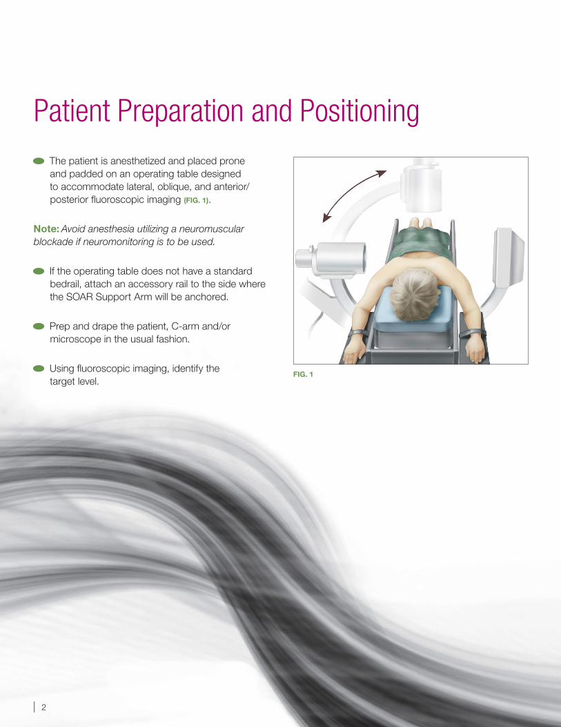
The patient is anesthetized and placed prone and padded on an operating table designed to accommodate lateral, oblique, and anterior/posterior fluoroscopic imaging (FIG. 1).
Note: Avoid anesthesia utilizing a neuromuscular blockade if neuromonitoring is to be used.
If the operating table does not have a standard bedrail, attach an accessory rail to the side where the SOAR Support Arm will be anchored.
Prep and drape the patient, C-arm and/or microscope in the usual fashion.
Using fluoroscopic imaging, identify the target level.
Patient Preparation and Positioning
SOAR Retractor System Surgical Technique 3 |
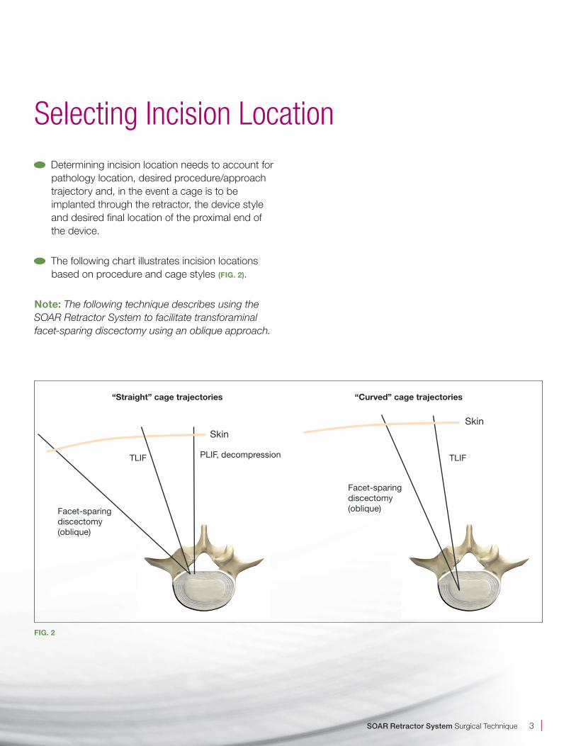
Determining incision location needs to account for pathology location, desired procedure/approach trajectory and, in the event a cage is to be implanted through the retractor, the device style and desired final location of the proximal end of the device.
The following chart illustrates incision locations based on procedure and cage styles (FIG. 2).
Note: The following technique describes using the SOAR Retractor System to facilitate transforaminal facet-sparing discectomy using an oblique approach.
Selecting Incision Location
SkinSkin
Facet-sparingdiscectomy(oblique)
Facet-sparingdiscectomy(oblique)
TLIF TLIFPLIF, decompression
FIG. 2
“Curved” cage trajectories“Straight” cage trajectories
| 4
Insert the Guide Pin at the desired incision site. Target the facet joint and advance along the desired trajectory using fluoroscopic guidance. Tap the Guide Pin lightly to anchor into bone. Make a 2-3 cm incision that penetrates through the subcutaneous fascia (FIG. 3).
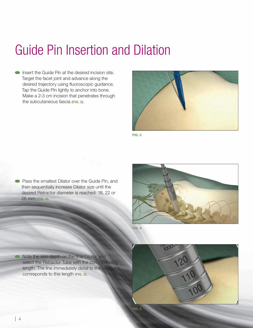
Pass the smallest Dilator over the Guide Pin, andthen sequentially increase Dilator size until thedesired Retractor diameter is reached: 18, 22 or26 mm (FIG. 4).
Note the skin depth on the final Dilator and select the Retractor Tube with the corresponding length. The line immediately distal to the numbers corresponds to this length (FIG. 5).
Guide Pin Insertion and Dilation
FIG. 3
FIG. 4
FIG. 5
SOAR Retractor System Surgical Technique 5 |
FIG. 6
FIG. 7
Attach the Retractor Tube to the Top Ring by aligning the flats on the Retractor Tube with the flats in the Top Ring. Press the components together and tighten the thumbscrew on the Top Ring to lock the components together (FIG. 6).
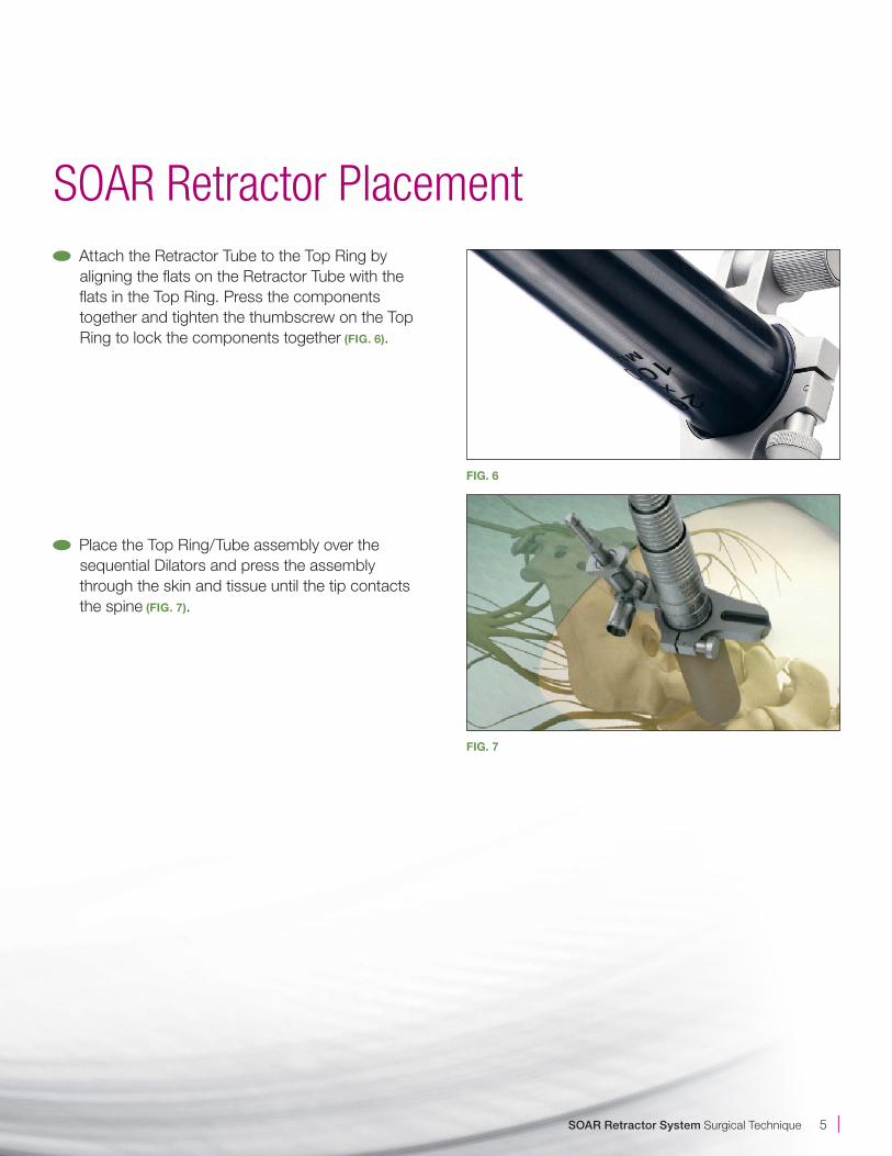
Place the Top Ring/Tube assembly over thesequential Dilators and press the assemblythrough the skin and tissue until the tip contactsthe spine (FIG. 7).
SOAR Retractor Placement
| 6
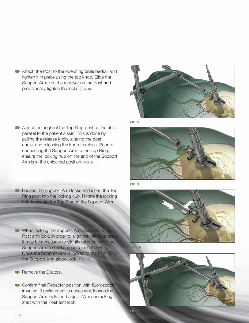
Attach the Post to the operating table bedrail and tighten it in place using the top knob. Slide the Support Arm into the receiver on the Post and provisionally tighten the locks (FIG. 8).
Adjust the angle of the Top Ring post so that it isparallel to the patient’s skin. This is done by pulling the release knob, altering the post angle, and releasing the knob to relock. Prior to connecting the Support Arm to the Top Ring, ensure the locking hub on the end of the Support Arm is in the unlocked position (FIG. 9).
Loosen the Support Arm locks and insert the TopRing post into the locking hub. Rotate the lockinghub to secure the Top Ring to the Support Arm (FIG. 10).
When locking the Support Arm, begin with the Post arm lock. In order to align the interface teeth, it may be necessary to slightly raise or lower the Support Arm a small amount along the Post. Once the Support Arm is locked to the Post, lock the Support Arm elbow lock (FIG. 11).
Remove the Dilators.
Confirm final Retractor position with fluoroscopic imaging. If realignment is necessary, loosen the Support Arm locks and adjust. When relocking, start with the Post arm lock.
FIG. 8
FIG. 9
FIG. 10
FIG. 11
SOAR Retractor System Surgical Technique 7 |
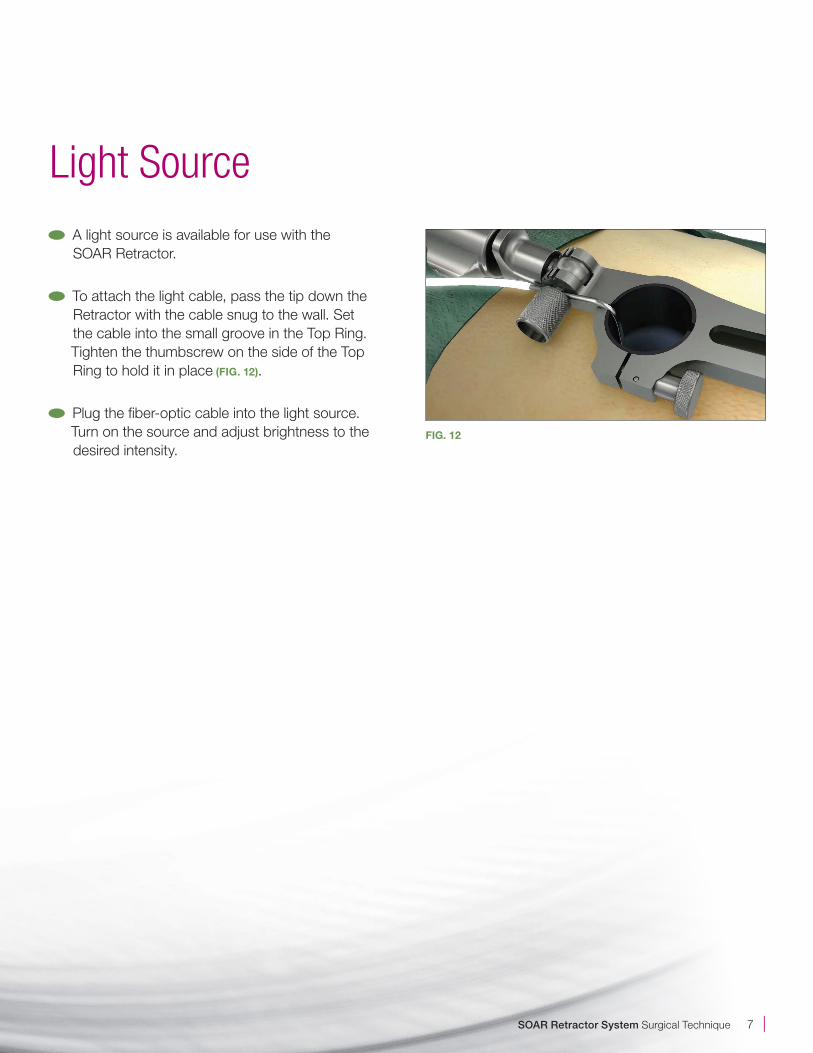
A light source is available for use with the SOAR Retractor.
To attach the light cable, pass the tip down the Retractor with the cable snug to the wall. Set the cable into the small groove in the Top Ring. Tighten the thumbscrew on the side of the Top Ring to hold it in place (FIG. 12).
Plug the fiber-optic cable into the light source. Turn on the source and adjust brightness to the desired intensity.
Light Source
FIG. 12
| 8
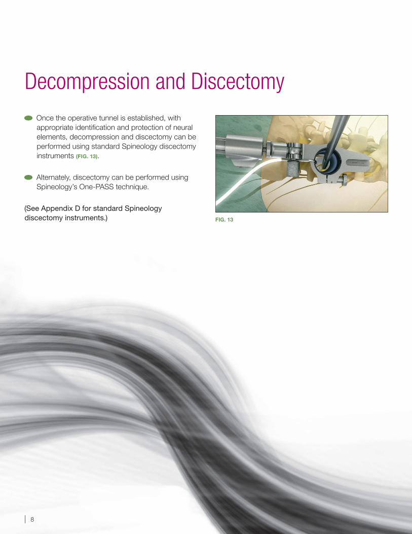
Once the operative tunnel is established, with appropriate identification and protection of neural elements, decompression and discectomy can be performed using standard Spineology discectomy instruments (FIG. 13).
Alternately, discectomy can be performed using Spineology’s One-PASS technique.
(See Appendix D for standard Spineology discectomy instruments.)
Decompression and Discectomy
FIG. 13
SOAR Retractor System Surgical Technique 9 |
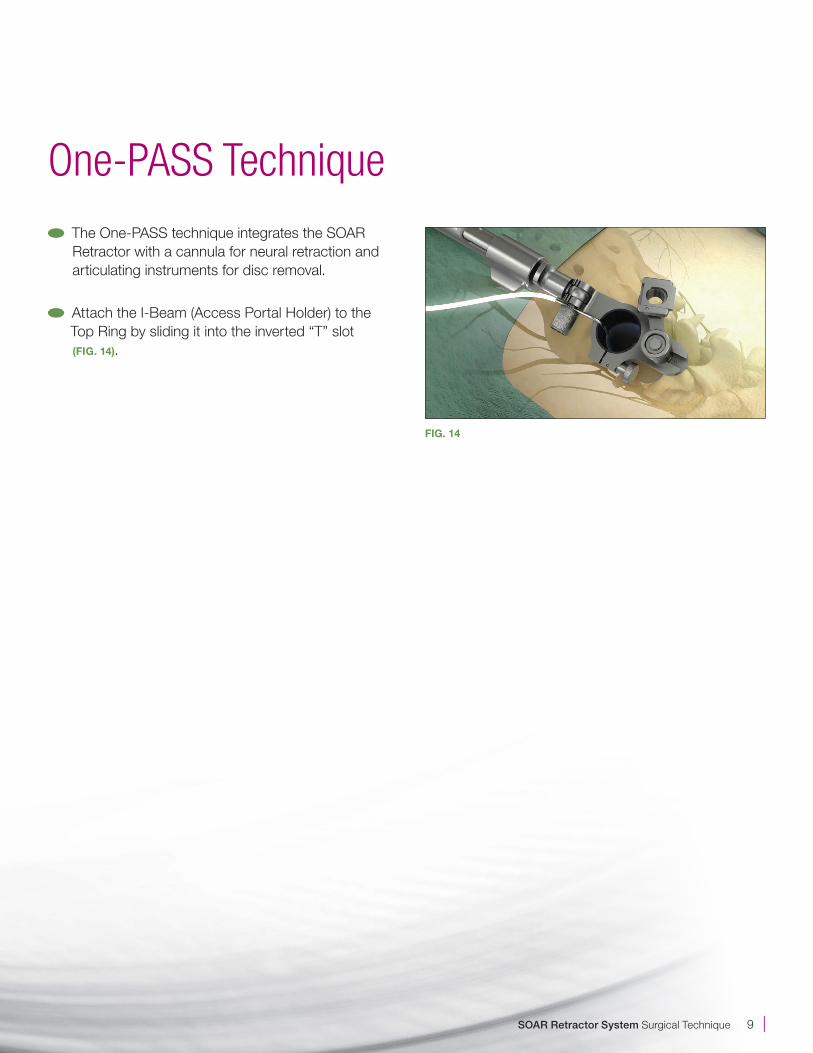
The One-PASS technique integrates the SOAR Retractor with a cannula for neural retraction and articulating instruments for disc removal.
Attach the I-Beam (Access Portal Holder) to the Top Ring by sliding it into the inverted “T” slot (FIG. 14).
One-PASS Technique
FIG. 14
| 10
FIG. 16
FIG. 17
FIG. 15
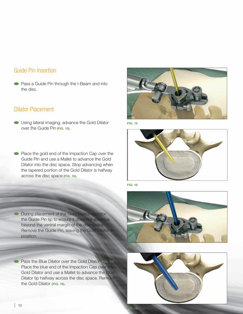
Guide Pin Insertion
Pass a Guide Pin through the I-Beam and into the disc.
Dilator Placement
Using lateral imaging, advance the Gold Dilator over the Guide Pin (FIG. 15).
Place the gold end of the Impaction Cap over the Guide Pin and use a Mallet to advance the Gold Dilator into the disc space. Stop advancing when the tapered portion of the Gold Dilator is halfway across the disc space (FIG. 16).
During placement of the Gold Dilator, monitor the Guide Pin tip to ensure it does not advance beyond the ventral margin of the disc space. Remove the Guide Pin, leaving the Gold Dilator in position.
Pass the Blue Dilator over the Gold Dilator (FIG. 17). Place the blue end of the Impaction Cap over the Gold Dilator and use a Mallet to advance the Blue Dilator tip halfway across the disc space. Remove the Gold Dilator (FIG. 18).
FIG. 18
SOAR Retractor System Surgical Technique 11 |
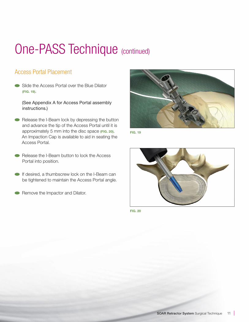
Access Portal Placement
Slide the Access Portal over the Blue Dilator (FIG. 19).
(See Appendix A for Access Portal assembly instructions.)
Release the I-Beam lock by depressing the button and advance the tip of the Access Portal until it is approximately 5 mm into the disc space (FIG. 20). An Impaction Cap is available to aid in seating the Access Portal.
Release the I-Beam button to lock the Access Portal into position.
If desired, a thumbscrew lock on the I-Beam can be tightened to maintain the Access Portal angle.
Remove the Impactor and Dilator.
FIG. 19
One-PASS Technique (continued)
FIG. 20
| 12
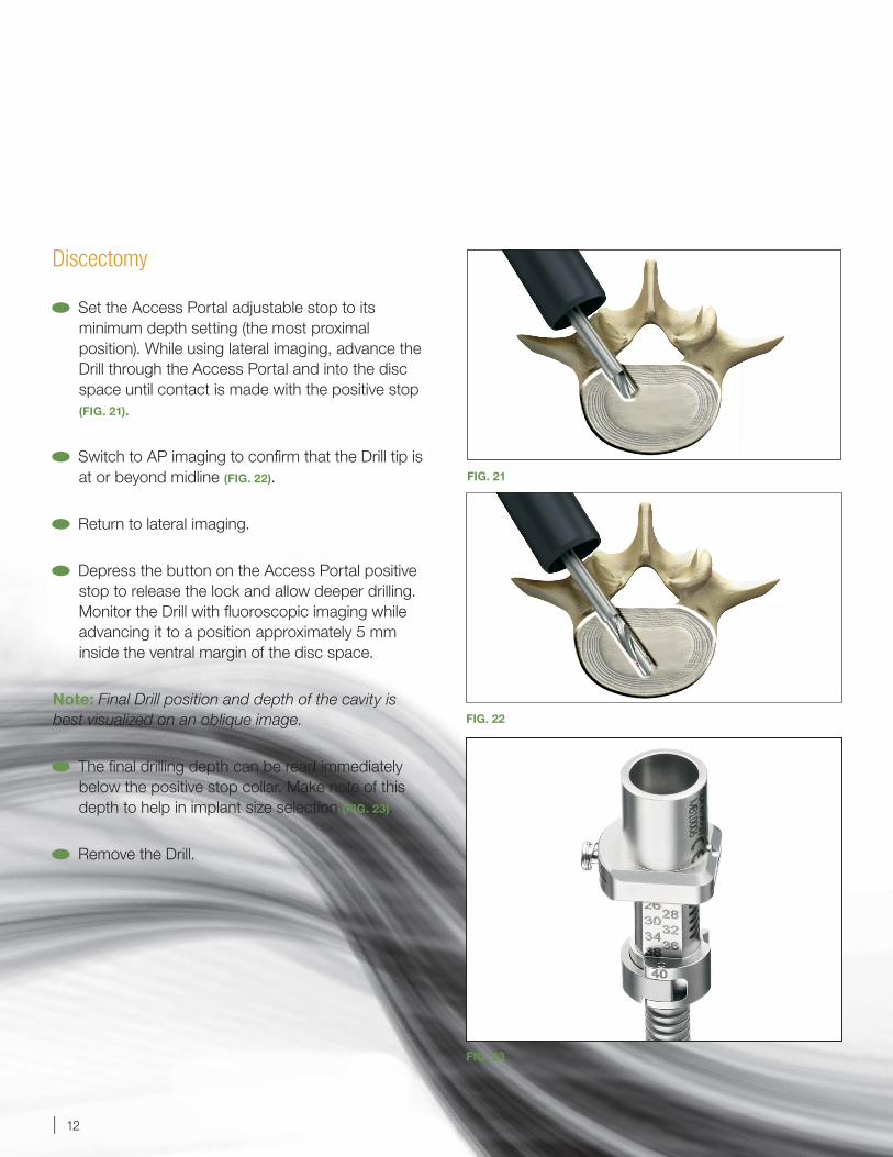
Discectomy
Set the Access Portal adjustable stop to its minimum depth setting (the most proximal position). While using lateral imaging, advance the Drill through the Access Portal and into the disc space until contact is made with the positive stop (FIG. 21).
Switch to AP imaging to confirm that the Drill tip is at or beyond midline (FIG. 22).
Return to lateral imaging.
Depress the button on the Access Portal positive stop to release the lock and allow deeper drilling. Monitor the Drill with fluoroscopic imaging while advancing it to a position approximately 5 mm inside the ventral margin of the disc space.
Note: Final Drill position and depth of the cavity is best visualized on an oblique image.
The final drilling depth can be read immediately below the positive stop collar. Make note of this depth to help in implant size selection (FIG. 23).
Remove the Drill.
FIG. 22
FIG. 21
FIG. 23
SOAR Retractor System Surgical Technique 13 |
FIG. 25
One-PASS Technique (continued)
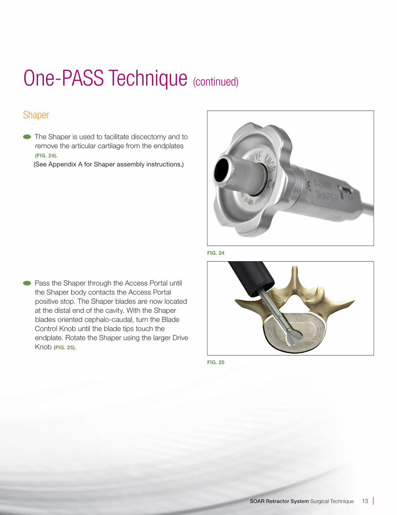
Shaper
The Shaper is used to facilitate discectomy and to remove the articular cartilage from the endplates (FIG. 24).
(See Appendix A for Shaper assembly instructions.)
Pass the Shaper through the Access Portal until the Shaper body contacts the Access Portal positive stop. The Shaper blades are now located at the distal end of the cavity. With the Shaper blades oriented cephalo-caudal, turn the Blade Control Knob until the blade tips touch the endplate. Rotate the Shaper using the larger Drive Knob (FIG. 25).
FIG. 24
| 14
FIG. 26
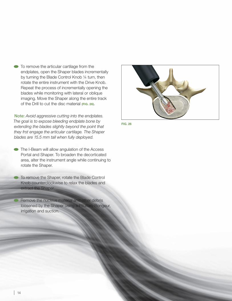
To remove the articular cartilage from the endplates, open the Shaper blades incrementally by turning the Blade Control Knob ¼ turn, then rotate the entire instrument with the Drive Knob. Repeat the process of incrementally opening the blades while monitoring with lateral or oblique imaging. Move the Shaper along the entire track of the Drill to cut the disc material (FIG. 26).
Note: Avoid aggressive cutting into the endplates. The goal is to expose bleeding endplate bone by extending the blades slightly beyond the point that they frst engage the articular cartilage. The Shaper blades are 15.5 mm tall when fully deployed.
The I-Beam will allow angulation of the Access Portal and Shaper. To broaden the decorticated area, alter the instrument angle while continuing to rotate the Shaper.
To remove the Shaper, rotate the Blade Control Knob counterclockwise to relax the blades and extract the Shaper.
Remove the nucleus material and other debris loosened by the Shaper using a Pituitary Rongeur, irrigation and suction.
SOAR Retractor System Surgical Technique 15 |
One-PASS Technique (continued)
FIG. 27
FIG. 28
FIG. 29
BackHoe Articulating Curette
The BackHoe Articulating Curette is used to cut disc material at the periphery of the cavity.
Position the BackHoe through the Access Portal until it contacts the positive stop.
Note: The hub on the BackHoe should always be in contact with the positive stop on the Access Portal while in use.
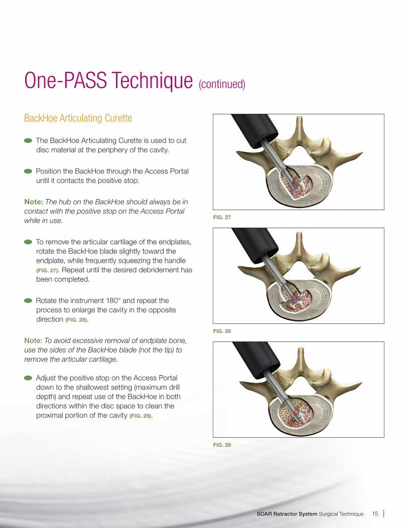
To remove the articular cartilage of the endplates, rotate the BackHoe blade slightly toward the endplate, while frequently squeezing the handle (FIG. 27). Repeat until the desired debridement has been completed.
Rotate the instrument 180° and repeat the process to enlarge the cavity in the opposite direction (FIG. 28).
Note: To avoid excessive removal of endplate bone,use the sides of the BackHoe blade (not the tip) toremove the articular cartilage.
Adjust the positive stop on the Access Portaldown to the shallowest setting (maximum drilldepth) and repeat use of the BackHoe in bothdirections within the disc space to clean theproximal portion of the cavity (FIG. 29).
| 16
Tissue Extraction
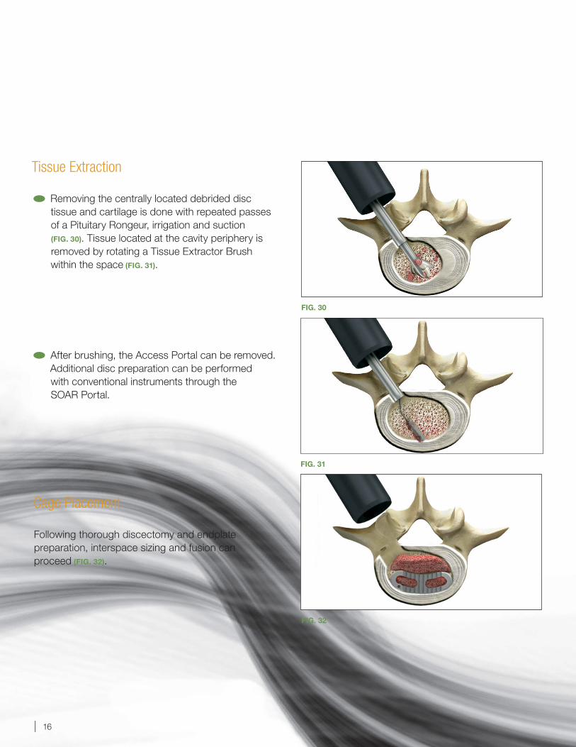
Removing the centrally located debrided disc tissue and cartilage is done with repeated passes of a Pituitary Rongeur, irrigation and suction (FIG. 30). Tissue located at the cavity periphery is removed by rotating a Tissue Extractor Brush within the space (FIG. 31).
After brushing, the Access Portal can be removed. Additional disc preparation can be performed with conventional instruments through the SOAR Portal.
Cage Placement
Following thorough discectomy and endplate preparation, interspace sizing and fusion can proceed (FIG. 32).
FIG. 31
FIG. 32
FIG. 30
SOAR Retractor System Surgical Technique 17 |
Appendix A: Instrument Assemblies
FIG. 35
FIG. 36
FIG. 33
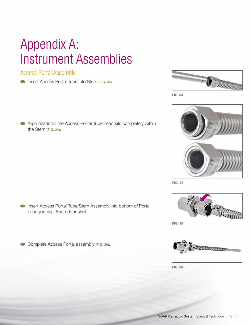
Access Portal Assembly Insert Access Portal Tube into Stem (FIG. 33).
Align heads so the Access Portal Tube head sits completely within the Stem (FIG. 34).
Insert Access Portal Tube/Stem Assembly into bottom of Portal head (FIG. 35). Snap door shut.
Complete Access Portal assembly (FIG. 36).
FIG. 34
| 18
FIG. 38
FIG. 37
FIG. 39
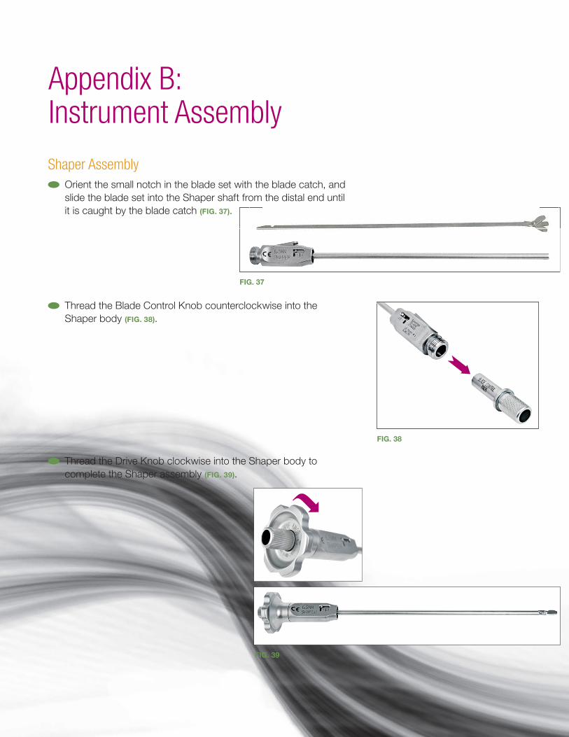
Shaper Assembly Orient the small notch in the blade set with the blade catch, and slide the blade set into the Shaper shaft from the distal end until it is caught by the blade catch (FIG. 37).
Thread the Blade Control Knob counterclockwise into the Shaper body (FIG. 38).
Thread the Drive Knob clockwise into the Shaper body to complete the Shaper assembly (FIG. 39).
Appendix B: Instrument Assembly
SOAR Retractor System Surgical Technique 19 |
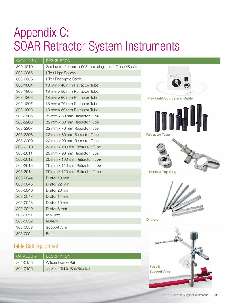
I-Tek Light Source and Cable
Retractor Tube
I-Beam & Top Ring
CATALOG # DESCRIPTION
300-1010 Guidewire, 2.4 mm x 508 mm, single use, Trocar/Round
303-0055 I-Tek Light Source
303-0056 I-Tek Fiberoptic Cable
303-1804 18 mm x 40 mm Retractor Tube
303-1805 18 mm x 50 mm Retractor Tube
303-1806 18 mm x 60 mm Retractor Tube
303-1807 18 mm x 70 mm Retractor Tube
303-1808 18 mm x 80 mm Retractor Tube
303-2205 22 mm x 50 mm Retractor Tube
303-2206 22 mm x 60 mm Retractor Tube
303-2207 22 mm x 70 mm Retractor Tube
303-2208 22 mm x 80 mm Retractor Tube
303-2209 22 mm x 90 mm Retractor Tube
303-2210 22 mm x 100 mm Retractor Tube
303-2611 26 mm x 90 mm Retractor Tube
303-2612 26 mm x 100 mm Retractor Tube
303-2613 26 mm x 110 mm Retractor Tube
303-2614 26 mm x 120 mm Retractor Tube
303-0044 Dilator 18 mm
303-0045 Dilator 22 mm
303-0046 Dilator 26 mm
303-0047 Dilator 14 mm
303-0048 Dilator 10 mm
303-0049 Dilator 6 mm
303-0051 Top Ring
303-0052 I-Beam
303-0053 Support Arm
303-0054 Post
Table Rail Equipment
CATALOG # DESCRIPTION
301-0158 Wilson Frame Rail
301-0156 Jackson Table Rail/Bracket
Appendix C: SOAR Retractor System Instruments
Post &
Support Arm
Dilators
| 20
To augment the utility of the SOAR Portal System and One-PASS technique, Spineology also offers a line of bayonet style discectomy instruments.
CATALOG # DESCRIPTION CATALOG # DESCRIPTION
303-0001 3 mm Straight Pituitary Rongeur 303-0033 11 mm Spineology Custom Shaver
303-0002 3 mm Up Biting Pituitary Rongeur 303-0034 12 mm Spineology Custom Shaver
303-0007 #4 Penfield 303-0035 13 mm Spineology Custom Shaver
303-0009 5 x 7.5 mm Straight Curette 303-0036 14 mm Spineology Custom Shaver
303-0010 5 x 7.5 mm 45° Forward Angled Curette 303-0059 15 mm Spineology Custom Shaver
303-0011 5 x 7.5 mm 45° Reverse Angled Curette 303-0060 16 mm Spineology Custom Shaver
303-0012 30° Angled Triangle Curette 303-0037 Right Facing 30° Serrated Curette
303-0015 Right Facing 30° Curette 303-0038 Left Facing 30° Serrated Curette
303-0016 Left Facing 30° Curette 303-0061 2 mm Bayonet Kerrison Rongeur
303-0019 Straight Triangle Curette 303-0062 3 mm Bayonet Kerrison Rongeur
303-0027 Base Tray 303-0063 4 mm Bayonet Kerrison Rongeur
303-0021 Sterilization Lid 303-0064 Fine Nerve Hook
303-0026 Upper Level Tray 303-0065 Bayonet Scalpel Handle
303-0023 Bayonet Nerve Root Retractor 303-0066 Long Murphy Ball Hook
301-0022 T-Handles 303-0067 #2 Ball Probe
303-0028 6 mm Spineology Custom Shaver 303-0068 #4 Ball Probe
303-0029 7 mm Spineology Custom Shaver 303-0069 8x10 Straight Serrated Curette
303-0030 8 mm Spineology Custom Shaver 303-0070 8x10 Right Facing 30° Serrated Curette
303-0031 9 mm Spineology Custom Shaver 303-0071 8x10 Left Facing 30° Serrated Curette
303-0032 10 mm Spineology Custom Shaver
Appendix D: Spineology Bayoneted Discectomy Instruments

© Spineology Inc. October 2011 L228 Rev. C
Additional U.S. and foreign patents pending.
Spineology Inc.7800 Third Street North, Suite 600Saint Paul, MN 55128-5455p: 888.377.4633 or 651.256.8500f: 651.256.8505
www.spineology.com
Spineology, the innovator in anatomy-conserving spine surgery, develops surgical techniques, instruments and implants that conserve spinal bone, nerve and muscle tissues. Spineology is committed to increasing procedural efficiency, reducing surgical morbidity and accelerating patient recovery. Learn more at spineology.com.