RESULTS OF CHARACTERIZATION TESTS OF THE …/67531/metadc891847/m2/1/high... · surfaces of a...
35
ORNL/TM-2003/115 Oak Ridge National Laboratory RESULTS OF CHARACTERIZATION TESTS OF THE SURFACES OF A COMMERCIALLY CARBURIZED AUSTENITIC STAINLESS STEEL December 2003 K. Farrell
Transcript of RESULTS OF CHARACTERIZATION TESTS OF THE …/67531/metadc891847/m2/1/high... · surfaces of a...

ORNL/TM-2003/115
Oak Ridge
National Laboratory
RESULTS OF CHARACTERIZATION TESTS OF THE SURFACES OF A COMMERCIALLY CARBURIZED AUSTENITIC STAINLESS STEEL
December 2003
K. Farrell

DOCUMENT AVAILABILITY
Reports produced after January 1, 1996, are generally available free via the U.S. Department of Energy (DOE) Information Bridge:
Web site: http://www.osti.gov/bridge Reports produced before January 1, 1996, may be purchased by members of the public from the following source:
National Technical Information Service 5285 Port Royal Road Springfield, VA 22161 Telephone: 703-605-6000 (1-800-553-6847) TDD: 703-487-4639 Fax: 703-605-6900 E-mail: [email protected] Web site: http://www.ntis.gov/support/ordernowabout.htm
Reports are available to DOE employees, DOE contractors, Energy Technology Data Exchange (ETDE) representatives, and International Nuclear Information System (INIS) representatives from the following source:
Office of Scientific and Technical Information P.O. Box 62 Oak Ridge, TN 37831 Telephone: 865-576-8401 Fax: 865-576-5728 E-mail: [email protected] Web site: http://www.osti.gov/contact.html
This report was prepared as an account of work sponsored by an agency of the United States Government. Neither the United States government nor any agency thereof, nor any of their employees, makes any warranty, express or implied, or assumes any legal liability or responsibility for the accuracy, completeness, or usefulness of any information, apparatus, product, or process disclosed, or represents that its use would not infringe privately owned rights. Reference herein to any specific commercial product, process, or service by trade name, trademark, manufacturer, or otherwise, does not necessarily constitute or imply its endorsement, recommendation, or favoring by the United States Government or any agency thereof. The views and opinions of authors expressed herein do not necessarily state or reflect those of the United States Government or any agency thereof.
ORNL/TM-2003/115
RESULTS OF CHARACTERIZATION TESTS OF THE SURFACES OF A COMMERCIALLY CARBURIZED AUSTENITIC STAINLESS STEEL
K. Farrell
December 2003
Prepared by OAK RIDGE NATIONAL LABORATORY
P.O. Box 2008 Oak Ridge, Tennessee 37831-6285
managed by UT-Battelle, LLC
for the U.S. DEPARTMENT OF ENERGY
under contract DE-AC05-00OR22725


CONTENTS
CONTENTS..................................................................................................................................... i
FIGURES........................................................................................................................................ ii
TABLES ........................................................................................................................................ iii
ABSTRACT.................................................................................................................................... 1
1.0 INTRODUCTION .................................................................................................................... 2
2.0 CHARACTERIZATION PROCEDURES ............................................................................... 2
3.0 RESULTS FOR KOLSTERISED ANNEALED DISK C14.................................................... 3
3.1 Surface distortion .................................................................................................................. 3 3.2 Hardness................................................................................................................................ 4 3.3 Toughness ............................................................................................................................. 7 3.4 Corrosion resistance.............................................................................................................. 8 3.5 The Penetration front ............................................................................................................ 9 3.6 Variation in layer thickness .................................................................................................. 9 3.7 Inclusions ............................................................................................................................ 10 3.8 A surface phase ................................................................................................................... 12 3.9 Lattice expansion ................................................................................................................ 14
3.9.1 Depth dependence of lattice expansion........................................................................ 15 3.10 Chemical analyses depth profiles...................................................................................... 16 3.11 TEM .................................................................................................................................. 17
4.0 RESULTS FOR KOLSTERISED TIG WELD H4. ............................................................... 18
4.1 Surface distortion of the weld ............................................................................................. 18 4.2 Cross section of the weld .................................................................................................... 18 4.3 Hardness of the weld........................................................................................................... 20
5.0 DISCUSSION AND CONCLUSIONS .................................................................................. 21
6.0 ACKNOWLEDGEMENTS.................................................................................................... 24
7.0 REFERENCES ....................................................................................................................... 24
DISTRIBUTION........................................................................................................................... 24
i

i

FIGURES Figure Page
Fig. 1. Distorted surface after Kolsterising. ................................................................................. 3 Fig. 2. Spiny structure in the deformed surface.............................................................................. 4 Fig. 3. Surface hardness as a function of indentation load at three randomly chosen regions on
Kolsterised disk C14. .......................................................................................................... 5 Fig. 4. Bodycote’s hardness-depth profiles for Kolsterised 316 stainless steel. ............................ 6 Fig. 5. Disk C14; hardness-depth profile for a 50g load................................................................ 7 Fig. 6. Curlicue of Kolsterised layer formed by action of a cutting tool pushing up from the lower
left corner of the field.......................................................................................................... 8 Fig. 7. Etched cross section though the Kolsterised specimen. ...................................................... 9 Fig. 8. Variation in thickness and surface roughness of Kolsterised layer at edge of piece........ 10 Fig. 9. Etched inclusion stringer in Kolsterised layer in disk C14............................................... 11 Fig. 10. Enhanced etching of inclusion stringers crossing the Kolsterised layer in 316L steel... 12 Fig. 11. Inclusion stringers traversing a Kolsterised layer in 316L austenitic steel.................... 12 Fig. 12. X-ray diffraction peaks from the surface of 316LN steel before and after Kolsterising. ..
............................................................................................................................................14 Fig. 13. Variation of the austenite lattice parameter with depth.................................................. 15 Fig. 14. Electron microprobe analyses of major metallic elements through the thickness of the
Kolsterised layer at three locations. ................................................................................. 16 Fig. 15. Electron microprobe analyses of carbon through the thickness of the Kolsterised layer at
three locations................................................................................................................... 17 Fig. 16. Distortion of originally polished surface of TIG weld H4. ............................................. 18 Fig. 17. Polished and etched cross section through the Kolsterised weld. .................................. 19 Fig. 18. Preferred etching of the *-ferrite phase in the Kolsterised portion of the weld. ............ 19 Fig. 19. Through-depth hardness profiles in welded specimen H4. ............................................. 20
ii


TABLES
Table Page Table 1. Summary of thickness measurements of Kolsterised layer………………………….10
Table 2. Nanohardnesses in the austenite matrix and in the *-ferrite phase in the Kolsterised
weld metal……………………………………………………………………………21
iii


ORNL/TM-2003/115
RESULTS OF CHARACTERIZATION TESTS OF THE SURFACES OF A
COMMERCIALLY CARBURIZED AUSTENITIC STAINLESS STEEL
ABSTRACT A commercial surface carburization treatment that shows promise for hardening the surfaces of the stainless steel target vessel of the Spallation Neutron Source against cavitation erosion and pitting caused by the action of pulsed pressure waves in the liquid mercury target has been investigated. To verify promotional claims for the treatment and to uncover any factors that might be of concern for the integrity of a carburized target vessel, some characterization tests of the nature of the surface layers of carburized austenitic 316LN stainless steel were conducted. The findings support most of the claims. The carburized layer is about 35µm thick. Its indentation hardness is about five times larger than that of the substrate steel and declines rapidly with depth into the layer. The surface is distorted by the treatment, and the austenite lattice is enlarged. The corrosion resistance of the carburized layer in an acid medium is greater than that for untreated austenite. The layer is not brittle; it is plastically deformable and is quite resistant to cracking during straining. Contrary to the provider’s assertations, the maximum carbon content of the layer is much less than 6-7wt% carbon, and the carbon is not simply contained in supersaturated solid solution; some of it is present in a previously unreported iron carbide phase located at the very surface. Large variations were found in the thickness of the layer, and they signify that controls may be needed to ensure a uniform thickness for treatment of the SNS target vessel. Inclusion stringers and *-ferrite phase embraced in the treated layer are less resistant to chemical attack than the treated austenite. From a cavitation pitting perspective under SNS bombardment, such non-austenitic phases may provide preferential sites for pitting. The shallow depth of the hardened layer will require use of protection measures to avoid mishandling damage to the layer during assembly and installation of a target vessel.
1

ORNL/TM-2003/115
RESULTS OF CHARACTERIZATION TESTS OF THE SURFACES OF A COMMERCIALLY CARBURIZED AUSTENITIC STAINLESS STEEL
1.0 INTRODUCTION The 316LN grade austenitic stainless steel vessel that holds the liquid mercury target in the Spallation Neutron Source will be subjected to pitting erosion due to collapse of cavities created in the mercury by the action of the pulsed proton beam. Techniques to mitigate the damage are under investigation. Generally, vessel materials that are hard and tough are more resistant than softer ones. One technique that has shown good promise is a surface hardening treatment known as Kolsterising. Kolsterising is the registered trade name of a proprietary surface carburization treatment for austenitic alloys provided by Bodycote Metal Technology Group from their division in Holland, now available in the USA at Bodycote Kolsterising North America, Boaz, Alabama. Special advantages are said to be improved resistance to pitting, stress corrosion, and crevice corrosion; increased resistance to wear and galling; and greater fatigue properties. According to Bodycote’s promotional information [1], Kolsterising is a process in which carbon is diffused into the surface of an austenitic alloy at low temperature, <300oC, from a gaseous atmosphere. The amount of carbon introduced is 6-7wt% at the surface, declining to zero at a depth that depends on the length of the treatment. Bodycote’s regular treatment purportedly affects a layer about 33µm deep. Within the layer, the infiltrated carbon is incorporated in supersaturated interstitial solid solution in the austenite phase of the steel. Accommodation of the carbon in the layer causes expansion of the affected austenite crystal lattice that is opposed by the unexpanded, and unhardened, substrate. This imposes compressive stresses in the layer. These stresses, combined with the changes in chemical composition, significantly harden the material to a depth of about 33µm. Hardness values of 1000-1200 DPN units (Vickers diamond pyramid number) are produced at the very surface and decline with depth to the substrate hardness of about 200 DPN at 30-40µm. Bodycote is unwilling or unable to disclose details of the Kolsterising treatment. SNS target vessels will be built to exacting standards and will be required to meet or exceed critical performance measures. If a Kolsterising treatment is to be incorporated in the fabrication procedure, it is essential that the provider’s claims be verified independently. To investigate Bodycote’s claims and to uncover any factors that might be of concern for the integrity of a Kolsterised target vessel, some characterization tests of the nature of the surface layers of Kolsterised austenitic 316LN stainless steel have been conducted at ORNL. The results are described herein. 2.0 CHARACTERIZATION PROCEDURES The characterization tests included optical metallographic examination, hardness tests, X-ray analyses for phase recognition and local stress determination, electron microprobe chemical
2

analyses, and transmission electron microscopy (TEM). Two 10mm diam. x 1mm thick disk specimens were studied. Disk #C14, was one of a number of such disks prepared for the LANSCE-WNR cavitation pitting test campaigns from 316LN stainless steel, Jessop heat # 18474. This is the heat from which the first target vessel will be fabricated. Before Kolsterising, disk C14 was machined and ground from plate stock, was vacuum annealed at 1050oC, and one of its flat faces was mechanically polished with 0.25µm diamond paste. Disk # H4 was cut from a TIG (tungsten electrode, inert gas atmosphere) weld made to join two 2.0mm thick annealed plates of a European-made 316 steel labeled EC316LN. Before Kolsterising, disk H4 was ground to 1.0mm thick and one of its flat faces was polished with 0.25µm diamond paste. Both disks were given the 33µm Kolsterising treatment by Bodycote. 3.0 RESULTS FOR KOLSTERISED ANNEALED DISK C14 3.1 Surface distortion Before Kolsterising, the as-polished, exterior flat surface of the disk was mirror smooth and no microstructural features could be discerned except for some inclusions. After the Kolsterising treatment, the surface was heavily wrinkled, Fig. 1. Grain boundaries were strongly demarked
Fig. 1. Distorted surface after Kolsterising.
and the grains contained extensive, coarse parallel slip and/or mechanical twin lines indicating the occurrence of considerable plastic deformation during Kolsterising. The shapes of the grains were not noticeably different from annealed grains. These features were seen without the aid of metallographic etching; they are revealed by surface relief alone. According to Bodycote, plastic
3

deformation of the surface does occur during Kolsterising. Closer examination of the deformed surface revealed the presence of a thin, discontinuous, spiny-like structure, almost hidden by the deformation bands. This structure was detected in all grains but was prominent in only few of them, as in the several lighter toned grains seen at higher magnification in Fig. 2. The structure is distinguished by the facts that its spines are shorter than the width of the grain and they lie in at least four orientations. In contrast, the deformation bands are linear and narrow, they usually span the full width of the grain, and they lie in only one or two directions except where they are perturbed by the presence of annealing twins. This reclusive, spiny feature is considered in more detail in section 3.8.
Fig. 2. Spiny structure in the deformed surface.
3.2 Hardness The hardness of the Kolsterised layer was measured in two ways, one directly on the flat surface then on a cross-section piece cut normal to the flat surface. The on-face tests were made to search for areal variation of hardness and to determine the effects of indentation load. Because the Kolsterised layer is quite thin, microhardness indentations made at normal loads of 500g or more will penetrate through the layer and will sample both the layer and the unhardened substrate, giving a falsely low measure of the layer hardness. Very light loads will test mostly the layer, but the size of the indentation will be small and will be subject to appreciably larger errors of measurement. Bodycote’s promotional literature quotes hardness values of 1000-1200 Vickers diamond pyramid number (DPN) for the surface hardness of Kolsterised austenitic stainless steel
4

measured with a load of 50g. That is a very substantial increase in hardness compared with the normal value of about 200 DPN for untreated annealed austenitic stainless steel. No data are available for areal variation of hardness on a Kolsterised layer. For the areal tests the disk was secured, with the originally as-polished surface facing up, to a flat, metal block using double-sided adhesive tape. Three regions on the face were chosen at random, and in each region seven tests were made at different loads between 50 and 2,000g. The results are shown in Fig. 3. They indicate good reproducibility from one region to another, implying no areal variation. They also show, very clearly, that with increasing load the contribution of the layer to the composite hardness is reduced as more and more of the softer substrate is sampled. The average hardness measured at 50g load is 1040 DPN, in agreement with Bodycote’s hardness of 1000-1200 DPN for Kolsterised austenitic stainless steel. The average hardness at 2000g load is 301 DPN versus 259 DPN measured for the untreated material, indicating only modest detection of the presence of the Kolsterised layer at high loads. Although these hardness tests show no variation with areal location, it is cautioned that they represent only a small area. Later we will see that thickness variations were detected in the Kolsterised layer. A reduced thickness might not affect the 50g surface hardness values nor the initial pitting resistance but it would impair the pitting resistance over time as the layer surface is eroded away, and would shorten the expected service lifetime of the target vessel.
Fig. 3. Surface hardness as a function of indentation load at three randomly chosen regions on
Kolsterised disk C14.
5

Since the Kolsterised layer is created by inward diffusion of carbon, there will be a concentration gradient of carbon in the layer, declining from a maximum at the surface to almost zero at the diffusion front. Likewise the hardness, which is supposedly governed by the concentration of carbon, will decrease with depth within the layer. To map such depth variation, a cross section piece is cut perpendicular to the treated surface and hardness measurements are made at small load at carefully measured distances below the specimen surface across the thickness of the layer and into the immediate unhardened host metal. Examples of hardness-depth profiles determined at 50g load for two Kolsterising treatments, 22µm and 33µm, in 316 austenitic stainless steel and published by Bodycote are reproduced in Fig. 4.
Fig. 4. Bodycote’s hardness-depth profiles for Kolsterised 316 stainless steel.
For the present determination of the hardness profile through the thickness of the disk, a chordal slice was cut from the disk and was mounted in cold-setting epoxy with the cut edge facing up. It was then polished to a mirror finish. Using a load of 50g, hardness impressions were made along a line lying at small angle to the specimen surface and passing across the Kolsterised layer into the parent metal. That way, the indentations could be made close to the surface but with sufficient separation between successive indentations that they did not interfere with one another. The combined results from two traverses are displayed in Fig. 5.
6
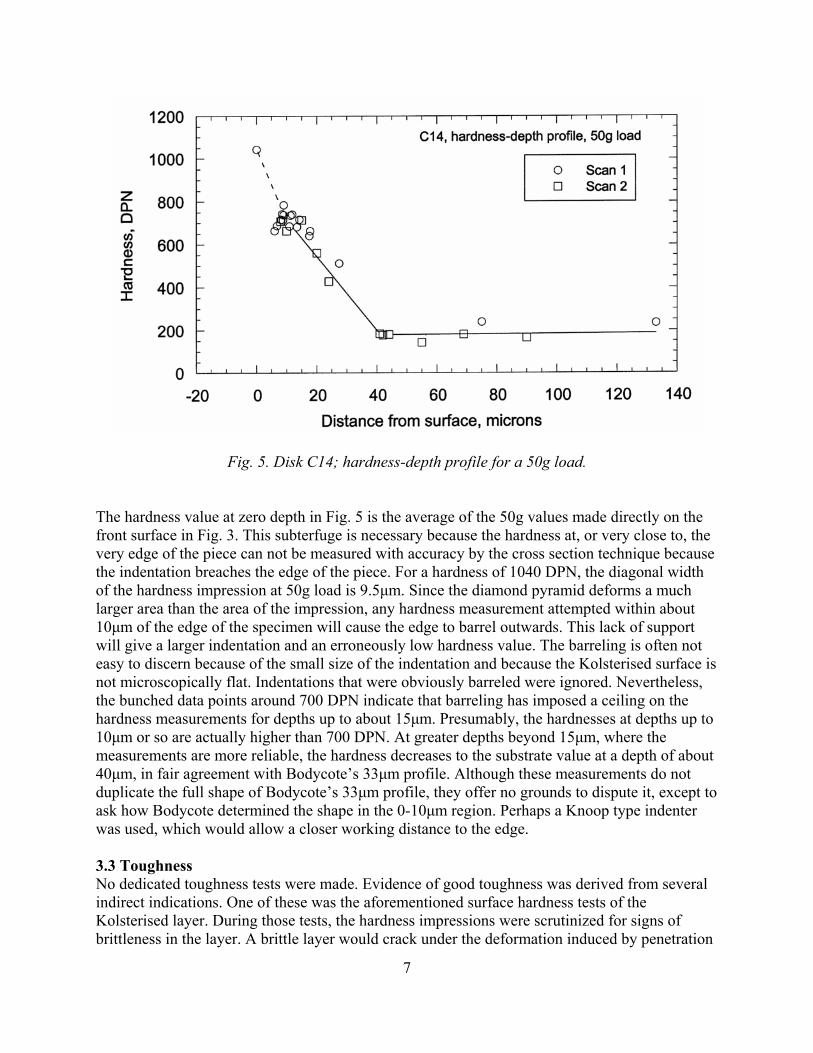
Fig. 5. Disk C14; hardness-depth profile for a 50g load.
The hardness value at zero depth in Fig. 5 is the average of the 50g values made directly on the front surface in Fig. 3. This subterfuge is necessary because the hardness at, or very close to, the very edge of the piece can not be measured with accuracy by the cross section technique because the indentation breaches the edge of the piece. For a hardness of 1040 DPN, the diagonal width of the hardness impression at 50g load is 9.5µm. Since the diamond pyramid deforms a much larger area than the area of the impression, any hardness measurement attempted within about 10µm of the edge of the specimen will cause the edge to barrel outwards. This lack of support will give a larger indentation and an erroneously low hardness value. The barreling is often not easy to discern because of the small size of the indentation and because the Kolsterised surface is not microscopically flat. Indentations that were obviously barreled were ignored. Nevertheless, the bunched data points around 700 DPN indicate that barreling has imposed a ceiling on the hardness measurements for depths up to about 15µm. Presumably, the hardnesses at depths up to 10µm or so are actually higher than 700 DPN. At greater depths beyond 15µm, where the measurements are more reliable, the hardness decreases to the substrate value at a depth of about 40µm, in fair agreement with Bodycote’s 33µm profile. Although these measurements do not duplicate the full shape of Bodycote’s 33µm profile, they offer no grounds to dispute it, except to ask how Bodycote determined the shape in the 0-10µm region. Perhaps a Knoop type indenter was used, which would allow a closer working distance to the edge. 3.3 Toughness No dedicated toughness tests were made. Evidence of good toughness was derived from several indirect indications. One of these was the aforementioned surface hardness tests of the Kolsterised layer. During those tests, the hardness impressions were scrutinized for signs of brittleness in the layer. A brittle layer would crack under the deformation induced by penetration
7
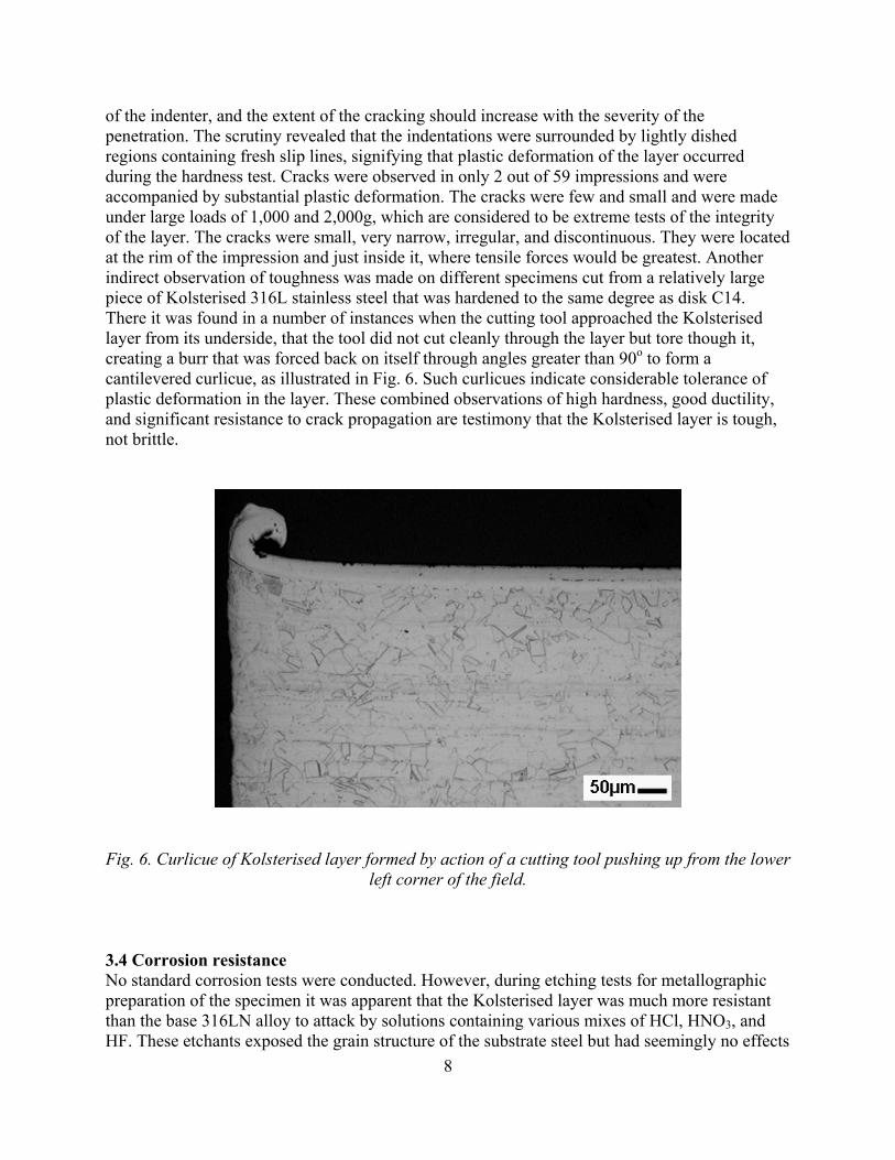
of the indenter, and the extent of the cracking should increase with the severity of the penetration. The scrutiny revealed that the indentations were surrounded by lightly dished regions containing fresh slip lines, signifying that plastic deformation of the layer occurred during the hardness test. Cracks were observed in only 2 out of 59 impressions and were accompanied by substantial plastic deformation. The cracks were few and small and were made under large loads of 1,000 and 2,000g, which are considered to be extreme tests of the integrity of the layer. The cracks were small, very narrow, irregular, and discontinuous. They were located at the rim of the impression and just inside it, where tensile forces would be greatest. Another indirect observation of toughness was made on different specimens cut from a relatively large piece of Kolsterised 316L stainless steel that was hardened to the same degree as disk C14. There it was found in a number of instances when the cutting tool approached the Kolsterised layer from its underside, that the tool did not cut cleanly through the layer but tore though it, creating a burr that was forced back on itself through angles greater than 90o to form a cantilevered curlicue, as illustrated in Fig. 6. Such curlicues indicate considerable tolerance of plastic deformation in the layer. These combined observations of high hardness, good ductility, and significant resistance to crack propagation are testimony that the Kolsterised layer is tough, not brittle.
Fig. 6. Curlicue of Kolsterised layer formed by action of a cutting tool pushing up from the lower
left corner of the field.
3.4 Corrosion resistance No standard corrosion tests were conducted. However, during etching tests for metallographic preparation of the specimen it was apparent that the Kolsterised layer was much more resistant than the base 316LN alloy to attack by solutions containing various mixes of HCl, HNO3, and HF. These etchants exposed the grain structure of the substrate steel but had seemingly no effects
8

on the Kolsterised layer. The layer remained featureless; no trace of the grain boundaries was discernible in it. The unetched layer contrasted sharply with the etched substrate and could be seen with the naked eye as a thin white skin around the specimen, shown in Fig. 7 at low magnification after swabbing in Glyceregia solution (30 parts each glycerol and HCl and 10 parts HNO3). This resistance of the Kolsterised layer to etching agrees with Bodycote’s claim of improved corrosion resistance.
Fig. 7. Etched cross section though the Kolsterised specimen.
3.5 The Penetration front From visual inspection, unaided or at low magnification, the penetration front of the Kolsterised layer seemed to end abruptly, with no visible evidence of a gradation. At the front, there was no pronounced interface. However, the apparent line between the layer and the unpenetrated portion of the steel seen in Fig. 7 is an optical deception. At higher magnification there is no line; the unetched layer simply merges with the etched substrate (see Figs. 9 and 10). This absence of a sharp physical interface boundary between the hardened surface and the relatively soft substrate is a sign that the hardened surface layer is not a separate layer or coat. It is suggestive of atomic cohesion of the penetration front with the substrate, and taken together with X-ray identification of the layer as expanded austenite (sections 3.9 and 4-0) it confirms that the layer is an integral part of the steel. It is consistent with a diffusion-controlled, carbon penetration process, as asserted by Bodycote. The flatness of the front was relatively independent of the original surface roughness. It was equally flat on the previously mirror-like polished surface (lower edge in Fig. 7) as on the as-ground upper surface. At the short edges of the piece that were rough machined before Kolsterising, the front was a little more irregular than at the ground and polished surfaces, and the outer surface of the layer was decidedly rougher, Fig. 8. There were no symptoms of preferential incursion of carbon along grain boundaries preceding the front. 3.6 Variation in layer thickness It is expected that uniformity of thickness of the Kolsterised layer on a target vessel will be a prerequisite for establishing a reliable performance lifetime for the vessel. Therefore, the thickness of the layer on the cross section chordal piece used for the hardness-depth profiles was measured carefully. The layer was not uniformly thick, nor was the outer surface uniformly flat. The layer on the prepolished surface was dished near the center length of the piece. This tapered thickness is seen in the bottom surface in Fig. 7. There, the depth varied from a maximum of 42µm to a minimum of 12.5µm at the base of the dished layer. The depth of the layer was measured at other positions around the piece. On the as-ground surface the depth was a uniform
9
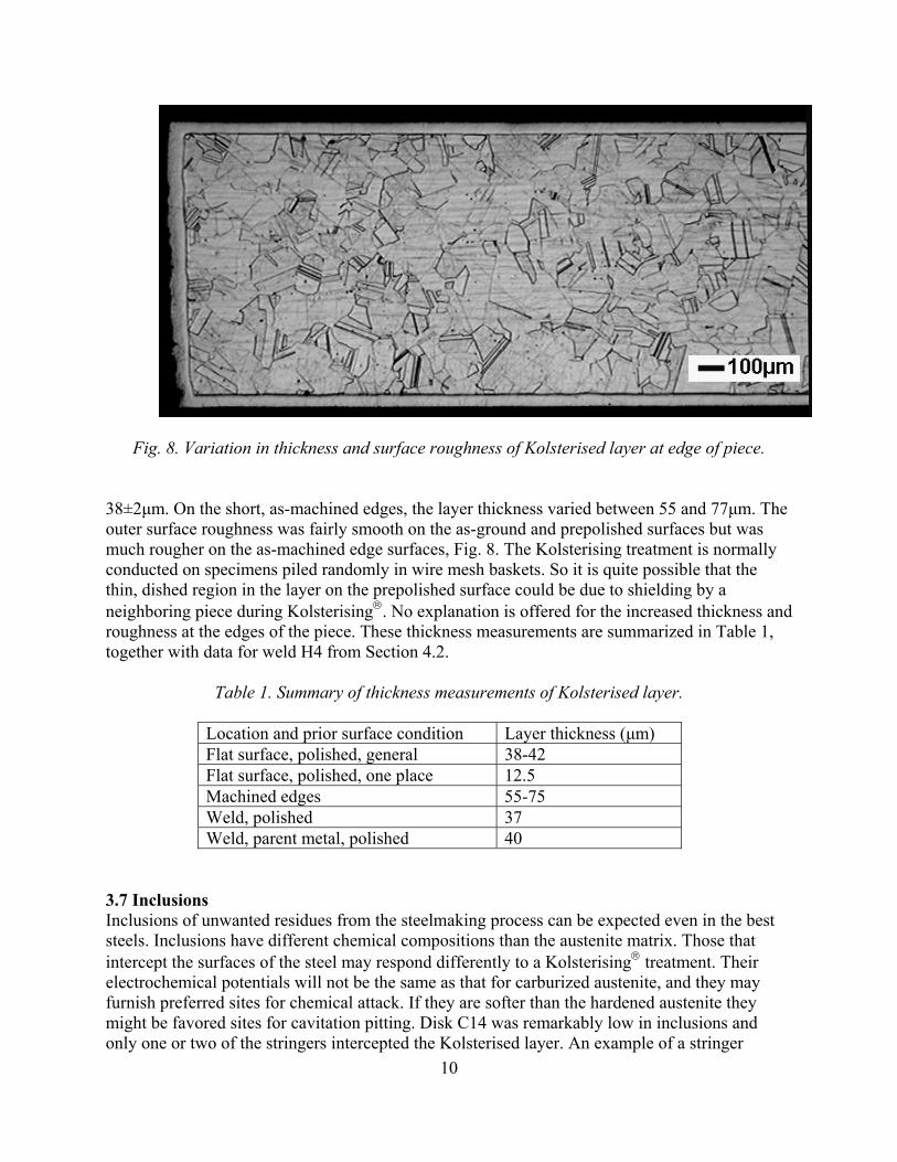
Fig. 8. Variation in thickness and surface roughness of Kolsterised layer at edge of piece.
38±2µm. On the short, as-machined edges, the layer thickness varied between 55 and 77µm. The outer surface roughness was fairly smooth on the as-ground and prepolished surfaces but was much rougher on the as-machined edge surfaces, Fig. 8. The Kolsterising treatment is normally conducted on specimens piled randomly in wire mesh baskets. So it is quite possible that the thin, dished region in the layer on the prepolished surface could be due to shielding by a neighboring piece during Kolsterising. No explanation is offered for the increased thickness and roughness at the edges of the piece. These thickness measurements are summarized in Table 1, together with data for weld H4 from Section 4.2.
Table 1. Summary of thickness measurements of Kolsterised layer.
Location and prior surface condition Layer thickness (µm) Flat surface, polished, general 38-42 Flat surface, polished, one place 12.5 Machined edges 55-75 Weld, polished 37 Weld, parent metal, polished 40
3.7 Inclusions Inclusions of unwanted residues from the steelmaking process can be expected even in the best steels. Inclusions have different chemical compositions than the austenite matrix. Those that intercept the surfaces of the steel may respond differently to a Kolsterising treatment. Their electrochemical potentials will not be the same as that for carburized austenite, and they may furnish preferred sites for chemical attack. If they are softer than the hardened austenite they might be favored sites for cavitation pitting. Disk C14 was remarkably low in inclusions and only one or two of the stringers intercepted the Kolsterised layer. An example of a stringer
10

completely within the layer and lying at a small angle to the surface is shown in Fig. 9. The position of the penetration front of the layer is indicated in this figure and in later figures by the white arrows. The stringer is more heavily etched than stringers in the substrate.
Fig. 9. Etched inclusion stringer in Kolsterised layer in disk C14. Preferred etching of inclusions in the Kolsterised layer is demonstrated more persuasively in Fig. 10, which is a piece of a different steel, a 316L grade containing many inclusion stringers, that has been Kolsterised like disk C14. In this case, the stringers lie at a steeper angle to the surface and some of them are partially within the Kolsterised layer and partially within the substrate. The inferior corrosion resistance of the stringers in the Kolsterised layer is demonstrated by the fact that those portions of the stringers within the substrate are lightly etched whereas the portions of the same stringers lying within the Kolsterised region are eaten away. Clearly, the Kolsterising treatment had an adverse effect on the corrosion resistance of the inclusion stringer. This did not happen with all stringers, so presumably their susceptibility to corrosive attack is dependent on their structure and chemical composition.
11
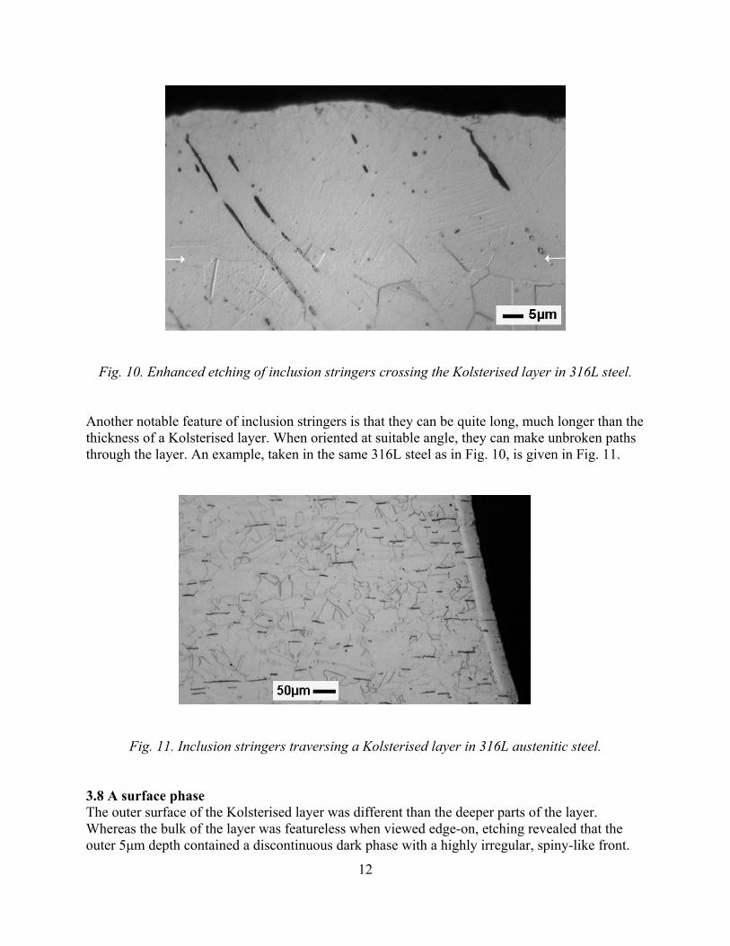
Fig. 10. Enhanced etching of inclusion stringers crossing the Kolsterised layer in 316L steel.
Another notable feature of inclusion stringers is that they can be quite long, much longer than the thickness of a Kolsterised layer. When oriented at suitable angle, they can make unbroken paths through the layer. An example, taken in the same 316L steel as in Fig. 10, is given in Fig. 11.
Fig. 11. Inclusion stringers traversing a Kolsterised layer in 316L austenitic steel. 3.8 A surface phase The outer surface of the Kolsterised layer was different than the deeper parts of the layer. Whereas the bulk of the layer was featureless when viewed edge-on, etching revealed that the outer 5µm depth contained a discontinuous dark phase with a highly irregular, spiny-like front.
12

This phase can be seen at the surface in the left side of Fig. 9. It is the spiny phase noted in section 3.1. The more uniform dark phase on the surface at the right of Fig. 9 is deformation bands. The spiny phase has not been reported by Bodycote, nor was it seen in the surface of the 316L steel, Fig. 10. At first, it was thought that the phase might be martensite caused by plastic deformation of the surface during Kolsterising. It is known that straining, either elastic or plastic, of Fe-Ni-Cr austenite can cause the formation of martensite [2,3]. However, the propensity for martensite formation declines markedly with temperature above room temperature, and is reduced by austenite stabilizing elements such as carbon. Since the Kolsterising treatment is conducted at temperatures below 300oC, and presumably as close to 300oC as possible to maximize the penetration of carbon, it is unlikely that martensite will form during Kolsterising. Nevertheless, plastic deformation and martensite may occur during cooling from the Kolsterising temperature. A phase similar to α'-martensite has been reported in the surface layer of 316 austenitic steel carburized in a methane gas plasma at 400-600oC [4], but was not detected in other work conducted under the same conditions by the same authors on 316 and 304 steels [5]. To identify the spiny phase, X-ray diffraction analyses were made on the outer face of the as-Kolsterised surface and on an annealed, non-Kolsterised, control specimen of the 316LN steel. The intensity peaks are shown in Fig. 12. Several features emerge from comparison of the two spectra. First, Kolsterising has introduced many more peaks. Second, the austenite peaks in the Kolsterised specimen are much broader and are shifted to lower angles than those in the annealed specimen. Analysis of the data indicated that the Kolsterised surface contained roughly equal parts of expanded austenite phase and a carbide phase. The diffraction pattern from the carbide phase coincided most closely with Fe5C2 Hagg (χ) carbide. However, the lattice parameter of the phase was closer to Mn5C2. Two small lines were not assignable to Fe5C2. One of these coincided with a line for Cr7C3, but no other supporting lines were found for Cr7C3 and therefore it was assumed that the chromium carbide phase was not present. The boxes at the base of Fig. 12 display the locations and scales of standard lines for martensite and Fe5C2. All of the standard Fe5C2 lines are found in the spectrum from the Kolsterised specimen except for one at 39o. With regard to martensite phase, the search for it was thwarted by the fact that the positions of the martensite lines coincide with some of those for Fe5C2. Thus, the presence of martensite can not be verified nor rejected on this X-ray evidence. The carbide phase has many more lines than the martensite, and there is no question of its presence. From lattice parameter measurements the carbide phase appeared to be free of stress.
13
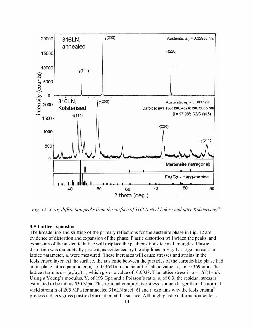
Fig. 12. X-ray diffraction peaks from the surface of 316LN steel before and after Kolsterising.
3.9 Lattice expansion
14
The broadening and shifting of the primary reflections for the austenite phase in Fig. 12 are evidence of distortion and expansion of the phase. Plastic distortion will widen the peaks, and expansion of the austenite lattice will displace the peak positions to smaller angles. Plastic distortion was undoubtedly present, as evidenced by the slip lines in Fig. 1. Large increases in lattice parameter, a, were measured. These increases will cause stresses and strains in the Kolsterised layer. At the surface, the austenite between the particles of the carbide-like phase had an in-plane lattice parameter, ain, of 0.3681nm and an out-of-plane value, aout, of 0.3695nm. The lattice strain is ε = (ain/aout)-1, which gives a value of -0.0038. The lattice stress is σ = εY/(1+ υ). Using a Young’s modulus, Y, of 193 Gpa and a Poisson’s ratio, υ, of 0.3, the residual stress is estimated to be minus 550 Mpa. This residual compressive stress is much larger than the normal yield strength of 205 MPa for annealed 316LN steel [6] and it explains why the Kolsterising process induces gross plastic deformation at the surface. Although plastic deformation widens
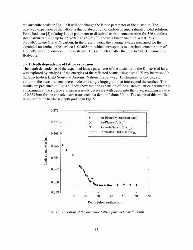
the austenite peaks in Fig. 12 it will not change the lattice parameter of the austenite. The observed expansion of the lattice is due to absorption of carbon in supersaturated solid solution. Published data [5] relating lattice parameter to dissolved carbon concentration for 316 stainless steel carburized with up to 2.5 wt%C at 450-500oC shows a linear function, a = 0.3597 + 0.0054C, where C is wt% carbon. In the present work, the average a value measured for the expanded austenite at the surface is 0.3688nm, which corresponds to a carbon concentration of 1.68 wt% in solid solution in the austenite. This is much smaller than the 6-7wt%C claimed by Bodycote. 3.9.1 Depth dependence of lattice expansion The depth dependence of the expanded lattice parameter of the austenite in the Kolsterised layer was explored by analysis of the energies of the reflected beams using a small X-ray beam spot in the Synchrotron Light Source at Argonne National Laboratory. To eliminate grain-to-grain variation the measurements were made on a single large grain that intercepted the surface. The results are presented in Fig. 13. They show that the expansion of the austenite lattice parameter is a maximum at the surface and progressively decreases with depth into the layer, reaching a value of 0.3595nm for the annealed substrate steel at a depth of about 30µm. The shape of this profile is similar to the hardness-depth profile in Fig. 5.
Fig. 13. Variation of the austenite lattice parameter with depth.
15
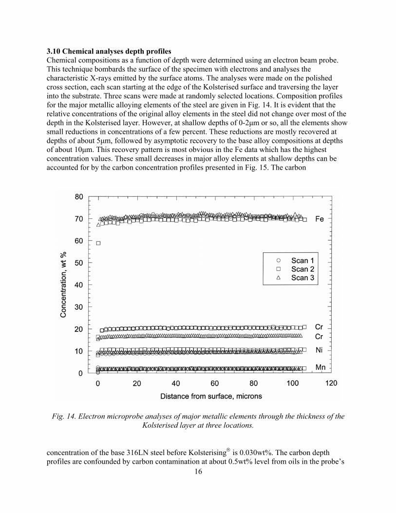
3.10 Chemical analyses depth profiles Chemical compositions as a function of depth were determined using an electron beam probe. This technique bombards the surface of the specimen with electrons and analyses the characteristic X-rays emitted by the surface atoms. The analyses were made on the polished cross section, each scan starting at the edge of the Kolsterised surface and traversing the layer into the substrate. Three scans were made at randomly selected locations. Composition profiles for the major metallic alloying elements of the steel are given in Fig. 14. It is evident that the relative concentrations of the original alloy elements in the steel did not change over most of the depth in the Kolsterised layer. However, at shallow depths of 0-2µm or so, all the elements show small reductions in concentrations of a few percent. These reductions are mostly recovered at depths of about 5µm, followed by asymptotic recovery to the base alloy compositions at depths of about 10µm. This recovery pattern is most obvious in the Fe data which has the highest concentration values. These small decreases in major alloy elements at shallow depths can be accounted for by the carbon concentration profiles presented in Fig. 15. The carbon
Fig. 14. Electron microprobe analyses of major metallic elements through the thickness of the Kolsterised layer at three locations.
16
concentration of the base 316LN steel before Kolsterising is 0.030wt%. The carbon depth profiles are confounded by carbon contamination at about 0.5wt% level from oils in the probe’s

vacuum system, and by inexplicable ripples in the data. The ripples are smallest in scan 3 where it is clear that the carbon concentration is largest at the very surface and decreases with depth to the base value at 25-30µm. The maximum carbon level at the Kolsterised surface, less the contamination background, is about 5wt% for scan 2, which has the largest decreases in the major metallic alloying elements, and is 2.5-3wt% for scans 1 and 2. The overall shapes of the carbon profiles with depth are similar to those for the hardness-depth profiles and the austenite lattice parameter-depth profile. The large variation in carbon concentration for the scans in the near-surface regions can be attributed to random sampling of the mixture of expanded austenite and the discontinuously distributed Fe5C2 phase by the electron beam. The austenite phase at the surface contains about 1.7%C according to section 3.9, and the carbide phase should have a stoichiometric carbon concentration of about 7.9wt%. The sample volume from which X-rays are
Fig. 15. Electron microprobe analyses of carbon through the thickness of the Kolsterised layer at three locations.
emitted under the electron beam is a cubic micrometer or more, which would undoubtedly encompass fractions of the carbide phase. Thus much of the 2.5-5wt%C found at the surface may derive from the Fe5C2 located in the outer surface region. 3.11 TEM Attempts were made to examine the microstructures in the Kolsterised region by TEM. Disks 3 mm diameter and 0.25mm thick containing the Kolsterised layer were excised by
17
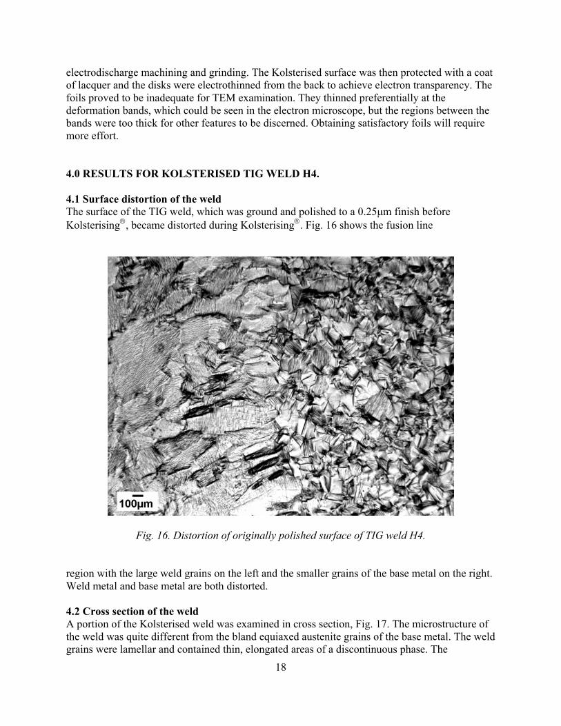
electrodischarge machining and grinding. The Kolsterised surface was then protected with a coat of lacquer and the disks were electrothinned from the back to achieve electron transparency. The foils proved to be inadequate for TEM examination. They thinned preferentially at the deformation bands, which could be seen in the electron microscope, but the regions between the bands were too thick for other features to be discerned. Obtaining satisfactory foils will require more effort. 4.0 RESULTS FOR KOLSTERISED TIG WELD H4. 4.1 Surface distortion of the weld The surface of the TIG weld, which was ground and polished to a 0.25µm finish before Kolsterising, became distorted during Kolsterising. Fig. 16 shows the fusion line
Fig. 16. Distortion of originally polished surface of TIG weld H4.
region with the large weld grains on the left and the smaller grains of the base metal on the right. Weld metal and base metal are both distorted. 4.2 Cross section of the weld A portion of the Kolsterised weld was examined in cross section, Fig. 17. The microstructure of the weld was quite different from the bland equiaxed austenite grains of the base metal. The weld grains were lamellar and contained thin, elongated areas of a discontinuous phase. The
18

morphology and general appearance of the phase, Fig. 18, is characteristic of the delta (*) ferrite phase usually found in fusion welds in austenitic steels [7,8]. The *-ferrite phase encompassed by the Kolsterised layer tended to be more prone to attack by the etchant than the *-ferrite phase in the substrate weld material. This observation agrees with Bodycote’s advisory that Kolsterising may not bestow corrosion resistance on the *-ferrite and duplex structures of austenite and *-ferrite may not deliver uniformity of properties in the Kolsterised layer. The thickness of the Kolsterised layer on the weld was uniform at about 37µm, versus about 40µm for the layer on the base metal. Large thickness variations like those seen in the unwelded C14 disk were not found.
Fig. 17. Polished and etched cross section through the Kolsterised weld.
Fig. 18. Preferred etching of the *-ferrite phase in the Kolsterised portion of the weld.
19

4.3 Hardness of the weld Results of hardness-depth profiles measured on the cross section piece of H4 across the thickness of the Kolsterised layer and into the substrate, one at the weld and the other on the base metal, are shown in Fig. 19. The two sets of data follow a single profile, of similar shape to the profile described earlier for specimen C14. One conclusion from the single curve presentation in Fig. 19 is that in spite of the presence of *-ferrite the weld has the same hardness as the base metal. This agrees with a report [7] that despite differences in crystal structure and chemical composition
Fig. 19. Through-depth hardness profiles in welded specimen H4.
between *-ferrite and austenite phases in welds in austenitic stainless steel, their hardnesses are comparable. However, the *-ferrite phase in the weld is thermally unstable at temperatures above about 475oC [7,8] and undergoes decomposition to G phase and M23C6 carbide, with attendant increase in hardness [7,8]. Therefore, the heat pulses suffered in multi-pass welds, such as ours, could cause the properties of the *-ferrite to vary. Another conclusion from Fig. 19 is that the presence of the *-ferrite phase does not seem to degrade the hardness of the weld in the Kolsterised region. Yet Bodycote recommends that materials offered for Kolsterising treatment should be ferrite-free, presumably because the ferrite phase will impair the properties of the Kolsterised product. In view of these warnings, we wondered whether the apparent lack of sensitivity of our hardness measurements to the presence of *-ferrite phase was due to a limitation of the test. It was noted that the packets of *-ferrite phase are narrow, 2µm or less, compared to the width of a hardness indentation in the layer, which is 10µm or more. Thus, the microhardness tests encompass a much larger volume of austenite than *-ferrite and may not be
20

especially responsive to changes in the *-ferrite. A test that sampled a much smaller volume should be more discriminatory. Therefore, some nanohardness tests were made to ascertain whether the hardness of the *-ferrite phase in the Kolsterised weld layer was different than its surrounding Kolsterised austenite. The results are given in Table 2. These nanohardness data values should not be compared with the earlier microhardness data. Nanohardness tests are different from microhardness tests and their hardness values are not strictly comparable.
Table 2. Nanohardnesses in the austenite matrix and in the *-ferrite phase in the Kolsterised weld metal.
Test # *-ferrite, GPa Test # Austenite,GPa
1 6.0 6 7.4 2 2.8 7 8.4 3 10.7 8 8.1 4 5.9 9 8.7 5 12.3 10 8.3
It can be seen in the table that five measurements made on the austenite matrix gave fairly reproducible nanohardness values of 7-8 Gpa. Five measurements attempted on five *-ferrite areas were not so consistent, giving values that ranged from about 3GPa to about 12GPa. In one of these latter cases, the 6.0 GPa value, it was found that the indentation missed the *-ferrite phase. Many of the *-ferrite particles contained small dark patches, possibly etched-out portions of the phase or maybe thermal decomposition products. It was concluded that this short exercise to test the relative hardnesses of the *-ferrite and the austenite phases in the Kolsterised portion of the weld indicated significant hardness variation in the *-ferrite but would require considerably more effort to give meaningful data. 5.0 DISCUSSION AND CONCLUSIONS The results of these characterization tests verify most of the promotional claims made by Bodycote for its Kolsterising treatment. The surface hardness claims are substantiated, as are the hardness-depth profiles. The surface is distorted by the treatment, and the austenite lattice is enlarged, as stated by Bodycote. The lattice expansion-depth profile is similar to the hardness-depth profile. The corrosion resistance of the Kolsterised layer in an acid medium is greater than that for untreated austenite. The layer is not brittle; it is plastically deformable and is quite resistant to cracking during straining. Contrary to Bodycote’s assertions, the maximum carbon content of the layer is much less than 6-7wt%, and the carbon is not simply contained in supersaturated solid solution; much of it seems to be present in a previously unreported iron carbide phase located non-uniformly at the very surface. Some inclusions and *-ferrite phase particles that were embraced by the Kolsterised layer became more sensitive to acid etching. Generally, many of these observations are similar to those reported by other researchers for stainless steel carburized by a plasma process conducted at temperatures between 300 and 600oC [4,5].
21

The hardness and toughness of the Kolsterised layer are impressive. The surface hardness is about 1040 DPN, which is more than five times the hardness of the annealed 316LN steel. The mechanism of the hardening is not fully clear. Bodycote’s literature cites a surface hardness of 1000-1200 DPN and implies that it is due entirely to the presence of 6-7wt%C entrained in supersaturated solid solution in the austenite. The carbon concentration profiles, austenite lattice parameter measurements and associated estimate of expansion stress determined herein agree in principle that some of the hardening ensues from solid solution hardening, but disagrees with Bodycote on the quantitative aspects. If Bodycote is correct, and if the rate of solid solution hardening scales linearly with carbon concentration, each 1%C will raise the hardness by about 140 DPN above the substrate hardness of 200 DPN. Therefore, our measured maximum carbon concentration of 1.7% in solid solution deduced from the expanded lattice parameter, will yield a surface hardness of about 440 DPN, which is far short of the measured hardness of 1040 DPN. However, the plastic deformation that occurs during the Kolsterising treatment will cause work hardening, and the carbide phase produced by the treatment will undoubtedly be harder than austenite. It is suggested that the balance of the increase in the hardness of the layer is provided by contributions from these two features. Only the outer 10-15:m of the layer is at maximum hardness. Although this thin layer is strong and tough it is not an armor plate. It can be penetrated by a sharp edge, as testified by the surface hardness measurements made under different loads in Fig. 3. This implies that the layer will not be immune to mishandling damage by scratches and dents during installation of the target vessel in the SNS. A scratch visible to the naked eye might be 10:m deep and will create a soft trough in the layer. Such damage will not be reparable except by a repeat Kolsterising treatment. If the layer is breached, the cavitation erosion rate at the breach will probably be the relatively high rate for the untreated substrate. Care will be needed to avoid such accidental damage. The thickness of the 33:m Kolsterised layer on disk C14 was quite variable. On disk H4 the layer was more uniform. A longer treatment that gives a thicker layer of about 45:m is available but judging from the wide variation in thickness measured in specimen C14, +30%/-60% of the nominal 33:m, there is no guarantee that the extra thickness will be any more uniform or any more beneficial than the 33:m treatment. Specimen C14 was selected at random for this work, and the thickness variations found in it are disturbing. The long-term resistance of the layer to cavitation pitting will presumably vary with the thickness of the layer. As mentioned earlier, the thin, dished region on specimen C14 might have resulted from accidental masking by other specimens in the batch Kolsterising treatment. For a target vessel, such masking must be avoided, and efforts should be made to measure or otherwise ensure that the layer thickness on the most susceptible parts of the target vessel surface is uniform and acceptable. The observations that the Kolsterising treatment seems to render some inclusions and the *-ferrite phase more susceptible to etching than the treated austenite implies reduced corrosion resistance for those microstructural features and thereby flags them as potential pitting corrosion sites. That does not necessarily make them the premier cavitation pitting sites. But if there is a connection between pitting corrosion susceptibility and cavitation pitting it becomes more significant because of the possibility the *-ferrite and inclusion stringers might provide short paths through the Kolsterised layer. The *-ferrite phase is networked through the layer, and the inclusion stringers, depending on their orientation, can penetrate more directly through the layer,
22

like tunnels. As such, they may offer preferred sites for pitting under the action of the pressure pulses during SNS service, possibly becoming deep “drill holes”. Such drill holes have been observed in cavitation pitting simulation tests, and further tests of Kolsterised specimens in an ultrasonic vibration system are showing preliminary signs that inclusions are choice pitting locations [9]. If these locations become drill holes and allow leakage of mercury through the wall they will prematurely shorten the service lifetime of the target vessel irrespective of the general rate of erosion of the vessel. Inclusions can be reduced by good steelmaking practice but it is unlikely they can be completely eliminated. Steps can be taken to minimize their effects on the SNS target vessel by paying attention to them during fabrication of the vessel, more specifically, by controlling their orientation with respect to the vessel wall thickness. When a cast steel billet is processed into bar or plate stock by forging, extrusion, or rolling, clusters of inclusions become strung out in the direction of the length of the product. If these stringers are made to lie parallel to the surface of the vessel wall they will be less likely to provide short-circuit drill hole paths through the wall than if they lie perpendicular to the wall. In that regard, a vessel fabricated from rolled sheet would be preferable to one machined from a large billet. In a formed sheet metal vessel the stringers will follow the curvature of the rounded nose of the vessel. In a vessel machined from a billet the stringers will pass through the wall at the curved nose, an undesirable situation. Another signal flag is raised by the presence of, and the tests made on, the *-ferrite phase in the TIG weld. The hardness of the phase seems to be quite variable. It is assumed that soft particles of *-ferrite will pit more readily, making them undesirable for the SNS target vessel. Bodycote warns against performing Kolsterising on ferrite phase, so presumably non-uniformity of properties is one reason for their concern. For the SNS, this problem can be handled easily by eliminating the *-ferrite phase or by placing the welds in the target vessel in positions where they will not be in contact with mercury. Elimination of *-ferrite phase can be achieved by using weld filler materials that stabilize austenitic phase and/or by post-weld heat treatments. Trials on weld coupons can be made to define the appropriate conditions. The target vessel design contains deep, narrow internal passageways that must be hardened like the external surfaces. Because Kolsterising is a diffusion process conducted in a gaseous atmosphere Bodycote expects that the layer produced on the inside surfaces of the deep passageways will be the same as that on more open surfaces and flat sections. To check that the layer is independent of the particular geometry of the SNS target, a large section of the nose portion of a mock-up of a full size target has been Kolsterised. It is undergoing examination to provide a map of layer thickness and hardness. Another concern with a Kolsterised layer is whether it will lose its hardness during the intense irradiation by protons and neutrons that a SNS target will experience. The reason for concern is that the migration of displaced atoms during irradiation might cause phase changes in the layer or may relieve internal stresses. In which cases, the hardness of the layer might fall. To investigate this prospect, an irradiation experiment with Kolsterised specimens is underway in the High Flux Isotope Reactor.
23
6.0 ACKNOWLEDGEMENTS It is a pleasure to acknowledge the contributions of fellow M & C Division staff members to various aspects of this work: J. D. Hunn for providing specimen C14; J. R. Mayotte for hardness tests and metallography; E. D. Specht and J. Pang for the X-ray work, L. R. Walker for electron microprobe analyses, K. A. Yarborough and E. A. Kenik for TEM, and A. Rar for nanohardness testing. 7.0 REFERENCES 1) “Kolsterising”, a hard copy of a CD ROM dated August 2001, distributed by Bodycote
Metal Technology; and some hard-copy fliers. Also, communications with Bodycote personnel.
2) Tryggve Angel, J. Iron and Steel Inst. 177 (1954) 165-174. 3) Dieter Fahr, Met. Trans. 2 (1971) 1883-1892. 4) Y. Sun, X. Li, and T. Bell, Mater. Science and Technology 15 (1999) 1171-1178. 5) Y. Sun, X. Li, and T. Bell, Surface Eng. 15 (1999) 49-54. 6) ASME Boiler and Pressure Vessel Code, Section II – Materials, Part D – Properties, 1998
Edition, July 1, 1998, The American Society of Mechanical Engineers, New York, New York.
7) S. A. David, J. M. Vitek, J. R. Keiser, and W. C. Oliver, Welding J. (1987) 235s-240s. 8) J. M. Vitek, S. A. David, D. J. Alexander, J. R. Keiser, and R. K. Nanstad, Acta metall.
mater. 39-4 (1991) 503-516. 9) S. J. Pawel, Oak Ridge National Laboratory, private communication, 2003.
DISTRIBUTION
24

INTERNAL DISTRIBUTION
1. R. R. Allen 2. R. E. Battle 3. E. E. Bloom 4. J. E. Cleaves 5. J. W. Cobb 6. H. H. Cromwell 7. J. R. DiStefano 8. D. A. Everitt 9. K. Farrell 10. T. A. Gabriel 11. J. R. Haines 12. L. L. Horton 13. J. D. Hunn 14. L. L. Jacobs 15. D. R. Johnson 16. J. O. Johnson 17. R. D. Lawson 18. D. C. Lousteau 19. E. T. Manneschmidt
20. L. K. Mansur 21. T. E. Mason 22. T. J. McManamy 23. G. E. Michaels 24. S. J. Pawel 25. M. J. Rennich 26. B. W. Riemer 27. S. L. Schrock 28. K. K. Shipley 29. P. T. Spampinato 30. C. H. Strawbridge 31. J. P. Strizak 32. P. F. Tortorelli 33. J. H. Whealton 34. D. K. Wilfert 35. G. L. Yoder 36. Central Research Library 37. ORNL Laboratory Records RC 38. ORNL Laboratory Records OSTI
EXTERNAL DISTRIBUTION 39. G. Bauer, Forschungszentrum Juelich, ESS Building 09.1, Leo-Brandt-Strasse, Juelich
52428, Germany. 40. T. Broome, ISIS, Rutherford-Appleton Laboratory, Chilton, Didcot, Oxon, OZ110Q,
United Kingdom. 41. J. M. Carpenter, Argonne National Laboratory, 9700 South Cass Ave, Bldg 360, IPNS
Division, Argonne, IL 60439. 42. M. Futakawa, Japan Atomic Energy Research Institute, Tokai-mura, Ibaraki-ken, 319-1195
Japan. 43. A. Jason, Los Alamos National Laboratory, P.O. Box 1663, H817 LANSCE-1, Los
Alamos, NM 87545. 44. P. Liaw, University of Tennessee, Department of Materials Science and Engineering, 427-
B Dougherty Engineering Building, Knoxville, TN 37996-2200. 45. M. Todosow, Brookhaven National Laboratory, P.O. Box 5000, Bldg 475B, Upton, NY
11973. 46. M. S. Wechsler, 106 Hunter Hill Place, Chapel Hill, NC 27514-9128. 47. W. Weng, Brookhaven National Laboratory, P.O. Box 5000, Bldg 911B, Upton, NY
11973. 48. F. W. Wiffen, 107 Whippoorwill Drive, Oak Ridge, TN 37830.
25