RESPONSE REQUEST FOR ADDITIONAL ENCLOSURE
11
ENCLOSURE 6 RESPONSE TO REQUEST FOR ADDITIONAL INFORMATION (RAI) 1 .d (MOV Performance Indicator Report for Cycle 21)
Transcript of RESPONSE REQUEST FOR ADDITIONAL ENCLOSURE

ENCLOSURE 6
RESPONSE TO REQUEST FOR ADDITIONAL INFORMATION (RAI) 1 .d(MOV Performance Indicator Report for Cycle 21)

NET20170002
1/23/2017
To: Eric Olson
Terry Becker
From: Derek Riegel
RE: Cycle 21 MDV Program Performance Indicator Report
The attached Motor Operated Valve (MOV) Program Performance Indicator Report for Cycle 21 wasprepared in accordance with the provisions of EDP-ZZ-01114, Motor Operated Valve Program Guide.
Key Accomplishments:
All of Callaway’s safety related MOVs are properly set up and in good working condition. Noadverse programmatic trends were identified in the Predictive Performance Reports. Adiscussion of the current set up of safety related MOVs can be found in Attachment 1 and issummarized below. Predictive Performance Reports for all MOVs tested in Cycle 21 can befound in Attachment 2.
o All safety related torque controlled rising stem MOVs are set up to meet the 25% targetmargin with the exception of EGHVOO6O and EGHVO13O (see discussion in Attachment1). Having 25% margin allows a 4-cycle/6-year static testing interval rather than OPtesting in order to meet the requirement for periodic verification of operability.
o All rising stem MOVs with an active safety function using a limit switch to open and/orclose have positive margin as required.
o All safety related butterfly MOVs have had their torque switches removed from thecontrol circuit. These MOVs must have positive macgin in the opening or closingdirection as required by their active safety functions. All butterfly MOVs meet theparameters required to eliminate the need for periodic differential pressure testing andmaintain the 4-cycle/6-year interval for periodic verification testing.
• The results of testing performed on rising stem MOVs during Cycle 21 confirms that there is nosignificant lubrication degradation at the stem to 5tem nut interface over the 18 monthlubrication interval.
1
Enclosure 6 to ULNRC-06410 Page 1 of 10

C.Planned Enhancements
• Crane Easy Torque Thrust sensors (Effs) will be used on butterfly valves to improve thequality of test data by directly measuring stem torque (Ref. CR 201608791).
• The implementation of an upgraded diagnostic test system, Crane Votes Infinity, isplanned for Cycle 22.
• An additional MOV engineer has been hired and will be qualified as an MOV Analyst andMOV Engineer to increase bench strength.
• Health Issue 2016019 has been initiated to address Callaway’s response to thelongstanding industry issue of Magnesium alloy rotor MOV motor failures.
• Addendums will be issued for calculations BB-143, EJ-30, EJ-21 Add 3, EM-20, and EM-21to determine the maximum allowable unseating force based on actuator capability as anenhancement action from CR 201608145.
Derek Riegel
MOV Engineer
Attachment 1: Cycle 21 Performance Indicator Report
Attachment 2: Cycle 21 Predictive Performance Reports
Cc: File A160.0446
Darrell Heckel
Curtis Wood
Dirk Raebel
(
2
lo,t
tt-3/?7
Enclosure 6 to ULNRC-06410 Page 2 of 10

CYCLE 21 MOV PROGRAM PERFORMANCE INDICATOR REPORTj
Attach ment 1
January 23, 2017
The Performance Indicator Report is comprised of the following sections:
This report provides an overview of the activities carried out by the Callaway Motor Operated Valve
(MOV) program during Cycle 21 in accordance with the requirements of EDP-ZZ-01114, Motor OperatedValve Program Guide. The period referred to as Cycle 21 began at the end of Refuel 20 on 11/22/2014
and ended at the finish of Refuel 21 on 5/10/2016.
1. Summary of historical diagnostic testing performed and discussion of diagnostic testingperformed in Cycle 21
2. Summary of the current setup of safety related MOVs in the GL 89-10 program3. Summary of major work performed on safety related MOVs in Cycle 21
4. Summary of CAR5/CR5 on safety related MOVs written or closed during Cycle 215. Summary of trends identified from predictive performance reports6. Actions to improve margin
7. Operating Experience Reviewed During Cycle 21
8. Planned actions to enhance the Callaway MOV program
1
Enclosure 6 to ULNRC-06410 Page 3 of 10

CYCLE 21 MOV PROGRAM PERFORMANCE INDICATOR REPORT, January 23, 2017
1. Summary of historical diagnostic testing performed and discussion of diagnostic testing
performed in Cycle 21
• There are currently 144 valves in the Callaway MOV program. All 144 have been static
baseline te5ted and 99 have been differential pressure tested.
• During Cycle 21, a total of 53 periodic verification tests were performed. These tests
included a differential pressure test of ALHV0005 and 8 baseline tests. The following MOVs
were baseline tested:
o ALHVOO34
o BGHV8112
o EFHVOO31
o EFHVOO47
o EFHVOO48
o EFHVOO49
o EFHVOOSO
o KCHVO253
• During Cycle 21, 40 Service and Inspect PMs and 96 actuator grease inspections were
performed on safety related MOVs.
2. Summary of the current setup of safety related MOVs in the GL 89-10 program
• All torque controlled rising stem MOVs with a safety function to close are set up to meet the
25% closing thrust margin requirement with the following exceptions:
o EGHVOO6O — 15% closing thrust margin; differential pressure testing is planned for
RF22 per job 15005097
o EGHVO13O - 4% closing thrust margin; differential pressure testing is planned for
RF22 per job 15003121
• All rising stem limit closed MOVs are set up with the required positive margin.
• All butterfly MOVs are set up with positive closing margin as required.
• All MOV5 at Callaway use limit switch control on the opening stroke. All MOV5 are set upwith positive opening margin.
2
Enclosure 6 to ULNRC-06410 Page 4 of 10
CYCLE 21 MOV PROGRAM PERFORMANCE INDICATOR REPORT, January 23, 2017
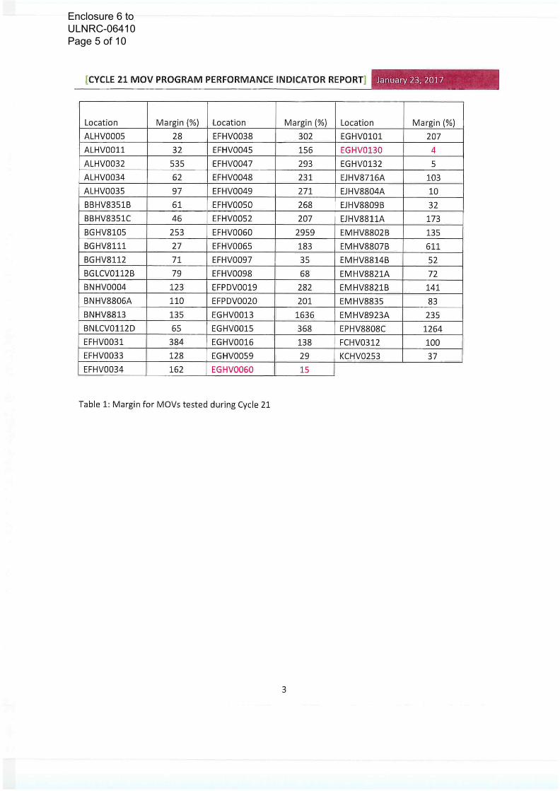
Table 1: Margin for MOVs tested during Cycle 21
Location Margin f%) Location Margin (¾) Location Margin (%)
ALHV0005 28 EFHVOO32 302 EGHVO1O1 207
ALHVOO11 32 EFHVOO45 156 EGHVO13O 4
ALHVOO32 535 EFHVOO47 293 EGHVQ132 5
ALHV0O34 62 EFHVOO48 231 EJHV8716A 103
ALHVOO3S 97 EFHVOO49 271 EJHV88O4A 10
BBHV8351B 61 EFHVOO5O 268 EJHV88O9B 32
BBHV$351C 46 EFHVOO52 207 EJHV8811A 173
BGHV81O5 253 EFHVOO6O 2959 EMHV88O2B 135
BGHV8111 27 EFHVOO65 183 EMHVS8O7B 611
BGHV8112 71 EFHVOO97 35 EMHV8S14B 52
BGLCVO112B 79 EFHVOO98 68 EMHV8821A 72
BNHV0004 123 EFPDVOO19 282 EMHV8821B 141
BNHV88O6A 110 EFPDVOO2O 201 EMHV8$35 83
3NHV8813 135 EGHVOO13 1636 EMHV8923A 235
BNLCVO112D 65 EGHVOO15 368 EPHV88O8C 1264
EFHVOO31 384 EGHVOO16 138 FCHVO312 100
EFHVOO33 128 EGHVOOS9 29 KCHVO2S3 37
EFHVOO34 162 EGHVOO6O 15
3
Enclosure 6 to ULNRC-06410 Page 5 of 10

CYCLE 21 MOV PROGRAM PERFORMANCE INDICATOR REPORT January 23, 2017
3. Summary of major work performed on safety related MOVs in Cycle 21
Service ServicePeriodic & Periodic &
Verification Inspect Packing Verification Inspect PackingLocation Test PM Adjustment Other Location Test PM Adjustment Other
ALHV000S X 1 EFHVOO66 X
AtHVOO11 X EFHVOO97 X X
ACHVOO32 X EFHVOO98 X X
ALHVDO34 X X 2 EFPDVOO19 X
ALHVOO35 X X EFPDVOO2O X
BBHV8351A X EGHVOO13 X X
BBHV83S1B X X X 3 EGHVOO15 X
BBHV83S1C X X X EGHVOO16 X X
BGHV8100 X EGHVOO59 X X
BGHV81G5 X EGHVOO6O X X
BGHV8S11 X X EGHVO1O1 X X
BGHV8YY2 X 2,7 EGHVO13O X
BGLCVO112B X X X 3 EGHVO132 X X
BGLCVO112C X EJFCVO611 X 3
BNHV0004 X X X EJHV87O1A X
BNHVS8G6A X X EJHV8716A X X X
BNHV8812A X 3 EJHV8SO4A X X
BNHV88 126 X UHV88O9B X X 3, 6
8NHV8813 X X EJHV8S11A X X
BNLCVO112D X X X EMHV88O2B X X
ECHVOO11 X EMHV88O3B X
EFHVOO23 X EMHV88O7B X X
EFHVOO31 X X 5 EMHV8814B X
EFHVOO33 X X EMHV8821A X X
EFHVOO34 X X EMHV8821B X X X
EFHVOO38 X 8 EMHV883S X X
EFHVOO45 X X EMHV8923A X
EFHVOO47 X X 5 EMHV8923B X
EFHVOG4S X X 5 ENHV0006 X
EFHVOO49 X S EPHV88O8B X
EFHVOO5O X X 5 EPHVS8OSC X X
EFHVOOS2 X X FCHVO312 X
EFHVOO6O X X KCHVO253 X 4
EFHVOO65 x x
Other
1- DP Test
2-Grease Change
3- Packing Force Test
4-Valve Inspection
S-Seat Ring Replacement
6- Repack
7-Motor Pinion Inspection8- Valve Replacement
Table 2: Major Work performed in Cycle 21
4
Enclosure 6 to ULNRC-06410 Page 6 of 10

CYCLE 21 MOV PROGRAM PERFORMANCE INDICATOR REPORT7 January 23, 2017
4. Summary of CAR5/CRs on safety related MOVs written or closed during Cycle 21
• Significance Level 1
o 201505796 - ALHV0007, MDAFP B to SG A flow control valve, (obj.) did not operate
electrically from the control room main control board fdev.), resulting in an inability
to remotely feed the A’ steam generator from the ‘B’ MDAFP and entry into
Technical Specification 3.7.5
• Root Cause - The reverse engineered design of the electronic positioner did
not meet the original design specification for the bridge rectifier circuit.
• Closed 4/9/2016
o 201505332 - ALHVOO11 (MDAFP to ‘C’ S/G HV) did not open on demand from the
Main Control Board (MCB), resulting in manual local operator action and delay in
steam generator level restoration.
• Root Cause - The implementation and oversight of programmatic controls
and programmatic changes to ALHV0005/7/9/11 did not ensure that the
written instructions MTE-ZZ-QA033, MOVATS UDS Testing of Torque
Controlled Modutronic Limitorque Motor Operated Rising Stem Valves,
were accurate. This resulted in the feedback potentiometer not being
calibrated, allowing it to go off scale.
• Closed 6/9/20 16
• Significance Level 2
o 201408399 - ALHV0005, MDAFP B TO S/G D HV, would not full close, resulting in
continued flow to EBBO1D, the RCS steam generator D and the need to secure
PALO1B, the ‘B’ MDAFP to prevent steam generator overfilling.
• Root Cause — The Close Torque Switch was set too low based on historical
DP Test data. This allowed the torque switch to open, preventing ALHV0005
from closing against pump flow.
• LTCA approved 12/9/2015
• Significance Level 3
o 201408399 - 201505965 - Cognitive trending has identified a potential adverse trend
for air and motor operated valves in the Auxiliary Feedwater (AL) system.
Continuing issues with system valves erode safety system health, and result in
additional MSPI failures, AP-913 consequential events, or full or partial loss of safetyfunction for the auxiliary feed water system.
• Common cause evaluation found three distinct types of failures that caused
the trend. No corrective action was determined beyond the CAs for the
individual CARs that were identified as being part of the adverse trend.
• Significance Level 4: 31 CARs/CRs
• Significance Level 5: 20 CARs/CR5
• Other Issues: 29 CARs/CR5
5
Enclosure 6 to ULNRC-06410 Page 7 of 10
CYCLE 21 MOV PROGRAM PERFORMANCE INDICATOR REPORT.
Cycle 21.
January 23, 2017
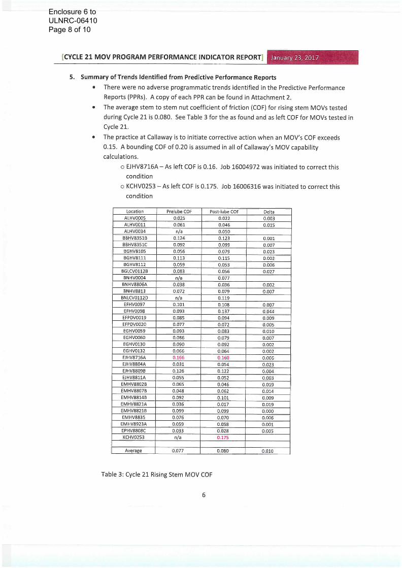
5. Summary of Trends Identified from Predictive Performance Reports
• There were no adverse programmatic trends identified in the Predictive PerformanceReports (PPRs). A copy of each PPR can be found in Attachment 2.
• The average stem to stem nut coefficient of friction (COF) for rising stem MOVs testedduring Cycle 21 is 0.080. See Table 3 for the as found and as left COF for MOVs tested in
• The practice at Callaway is to initiate corrective action when an MOV’s COF exceeds0.15, A bounding COF of 0.20 is assumed in all of Callaway’s MDV capability
o EJHV8716A—As left COF is 0.16. Job 16004972 was initiated to correct this
o KCHVO253 — As left COF is 0.175. Job 16006316 was initiated to correct this
calculations.
condition
condition
Location Prelube COF Post-lube COF DeltaALHV0005 0.025 0.022 0.003ALHV0O11 0.061 0.046 0.015ALHVOO34 n/a 0.050
BBHV8351B 0.124 0.123 0.001BBHV8351C 0.092 0.099 0.007BGHV81OS 0.056 0.079 0.023BGHV8111 0.113 0.115 0.002BGHV8112 0.059 0.053 0.006
BGLCVO112B 0.083 0.056 0.027BNHV0004 fl/a 0.077
BNHV88O6A 0.038 0.036 0.002BJHV8813 0,072 0.079 0.007
BNLCVO112D n/a 0.119EFHVOO97 0.101 0.108 0.007EFHVOO98 0.093 0.137 0,044
EFPDVOO19 0.085 0.094 0.009EFPDVOO2O 0.077 0.072 0.005EGHVOOS9 0.093 0.083 0.010EGHVOO6O 0.086 0.079 0.007EGHVO13O 0.090 0.092 0.002EGHVO132 0.066 0.064 0.002EJHV8716A 0.166 0.160 0.006EJHV88O4A 0.031 0.054 0.023EJHV88O9B 0.126 0.122 0.004LJHVSS11A 0.055 0.052 0.003
EMHV88O2B 0.065 0.046 0.019EMHVS8O7B 0.048 0.062 0.014EMHV8814B 0.092 0.101 0.009EMHV8821A 0.036 0.017 0.019EMHV8821B 0.099 0.099 0.000EMHV8835 0.076 0.070 0.006
EMHV8923A 0.059 0.058 0.001EPHVB8O8C 0.033 0.028 0.005KCHVO253 fl/a 0.175
Average 0.077 0.080 0.010
Table 3: Cycle 21 Rising Stem MDV COF
6
Enclosure 6 to ULNRC-06410 Page 8 of 10

CYCLE 21 MOV PROGRAM PERFORMANCE INDICATOR REPORT. January 23, 2017
6. Actions to Improve Margin
• DP Testing — As a corrective action for CAR 201408399, 13 torque controlled rising stemMOVs had their required DP Thrust to Close administratively raised to match that of
their sister valve with the highest requirement (Ref. RFR 201505952). DP testing will beperformed on each of these MOVs to verify the thrust required to close against designbasis differential pressure and flow.
o The following MOVs are impacted:
1. ALHV0005 — completed in RF21
2. ALHV0009—Job 15005094
3. BGHV8111—Job 15003115
4, EFHVOO97—Job 15003116
5. EGHVOO58—Job 15005095
6. EGHVOO59—Job 15005096
7. EGHVOOGO—Job 15005097
8. EGHVOO61—Job 15003120
9. EGHVO13O—Job 15003121
10. EGHVO13—Job 15005098
11. EJHV88O9B—Job 15003117
12. EMHV8SO2B—Job 15003118
13. EMHV8923A—Job 15003119
• Coefficient of Friction — As discussed above, Jobs 16004972 and 16006316 have beenwritten to correct the high COF for EJHV8716A and KCHVO253, respectively. Reducingthe COF will allow the valve to achieve a higher thrust for a given amount of torqueproduced by the Limitocque actuator.
7
Enclosure 6 to ULNRC-06410 Page 9 of 10

CYCLE 21 MOV PROGRAM PERFORMANCE INDICATOR REPORT
7. Operating Experience Reviewed During Cycle 21
January 23, 2017
High torque switch Contact resistance (dirtycontacts on new switch) prevented valve from
ICES closing. No procedural guidance to inspect new Revise maintenance procedure to inspect new253636 Hope Creek electrical components from stores and clean as torque/limit switches prior to installation. Ref. CAR(0E36346) 1 necessary. 201507996
Walworth flex wedge gate valve. Stem/Discseparation due to pressure locking or stress No action. Callaway does not have any MOVs made by
ICES corrosion cracking. Valve was opened with a Walworth, Follow up review may be required after318359 Columbia hot tap pushrod, Will repair in next outage. Columbia repairs valve and determines cause.
Foam vapor corrosion inhibitor devices found inICES actuator during bench test. Vendor requires Revise procedure to remove foam vapor corrosion311018 Catawba removal to maintain EQ. inhibitor devices if found. Ref. CAR 201501750
Rotork actuator motor shorted to ground whenthe handswitch was actuated for stroke time
ICES test. Most likely cause determined to be motor No action. Callaway does not have any Rotork actuators,321415 McGuire 1 quality, making this quality concern not applicable.
Valve failed to fully open during testing. Causedetermined to be excessive running torque in No action. Covered by existing program requirements.
ICES both directions due to packing load. Stem Also, MDVs at Callaway open on limit; full actuator torque321599 Limerick 2 cleaned/lubed, open torque switch adjusted, capability is available on open stroke.
Motor pinion key came out. Setscrew backedICES Browns Ferry off. Key Wasn’t adequately staked and motor No action. Motor pinion key/setscrew installation is320599 3 shaft was not drilled/dimpled, adequately covered in MTM-ZZ-QAOO6 Attachment 8.
Table 4: Cycle 21 CE Reviewed
8. Planned actions to enhance the Callaway MOV program
• Crane Easy Torque Thrust sensors (Effs) will be used on butterfly valves to improve thequality of test data by directly measuring stem torque (Ref. CR 201608791).
• The implementation of an upgraded diagnostic test system, Crane Votes Infinity, isplanned for Cycle 22.
• An additional MOV engineer has been hired and will be qualified as an MOV Analyst andMOV Engineer to increase bench strength.
• Health Issue 2016019 has been initiated to address Callaway’s response to thelongstanding industry issue of Magnesium alloy rotor MDV motor failures.
• Addendums will be issued for calculations 88-143, EJ-30, Ei-21 Add 3, EM-20, and EM-21to determine the maximum allowable unseating force based on actuator capability as anenhancement action from CR 201608145.
8
Enclosure 6 to ULNRC-06410 Page 10 of 10