Research Paper Diminished reality using plane-sweep ...
10
Special issue: 3D image and video technology Progress in Informatics, No. 7, pp.11–20, (2010) 11 Research Paper Diminished reality using plane-sweep algorithm with weakly-calibrated cameras Songkran JARUSIRISAWAD 1 , Takahide HOSOKAWA 2 , and Hideo SAITO 3 1,2,3 Department of Infomation and Computer Science, Keio University ABSTRACT We present a plane-sweep algorithm for removing occluding objects in front of the objective scene from multiple weakly-calibrated cameras. Projective grid space (PGS), a weak cameras calibration framework, is used to obtain geometrical relations between cameras. Plane-sweep algorithm works by implicitly reconstructing the depth maps of the targeted view. By exclud- ing the occluding objects from the volume of the sweeping planes, we can generate new views without the occluding objects. The results show the effectiveness of the proposed method and it is fast enough to run in several frames per second on a consumer PC by implementing the proposed plane-sweep algorithm in graphics processing unit (GPU). KEYWORDS Diminished reality, plane-sweep, real-time, video-based rendering, Graphics processing unit (GPU) 1 Introduction Augmented reality (AR) [1], [2] is a term of the tech- nology that composites the computer generated image to the real image viewed by the user. AR supplements the computer generated image to the real scene, rather than completely replacing it. Ideally, the rendered vir- tual object should coexist in the scene realistically so that the viewer cannot distinguish between the real and the virtual ones. In contrast, the goal of diminished reality research (so-called mediated reality [3]) is to generate the im- ages in which some real objects are deliberately re- moved. This means that whatever is behind the object should be rendered when the occluding objects are re- moved. The information about occluded area normally comes from either the other camera views or from the same camera view but at the different frames in which the occluded area is seen. This paper proposed a new method of diminished reality from multiple weakly-calibrated cameras using plane-sweep algorithm. Plane-sweep algorithms have Received September 30, 2009; Revised December 15, 2009; Accepted January 4, 2010. 1) [email protected], 2) [email protected], 3) [email protected] been proposed in the literatures [4]–[7] to generate free viewpoint videos. In this paper, we adapted plane- sweep algorithm to use for diminished reality applica- tions with weakly-calibrated cameras. Fig. 1 illustrates what our proposed system does. From several cameras, user can create new view images between any cameras while also remove the occluding object to reveal the Fig. 1 Overview of the proposed system. DOI: 10.2201/NiiPi.2010.7.3 c 2010 National Institute of Informatics
Transcript of Research Paper Diminished reality using plane-sweep ...

Special issue: 3D image and video technology
Progress in Informatics, No. 7, pp.11–20, (2010) 11
Research Paper
Diminished reality using plane-sweep algorithmwith weakly-calibrated cameras
Songkran JARUSIRISAWAD1, Takahide HOSOKAWA2, and Hideo SAITO3
1,2,3Department of Infomation and Computer Science, Keio University
ABSTRACTWe present a plane-sweep algorithm for removing occluding objects in front of the objectivescene from multiple weakly-calibrated cameras. Projective grid space (PGS), a weak camerascalibration framework, is used to obtain geometrical relations between cameras. Plane-sweepalgorithm works by implicitly reconstructing the depth maps of the targeted view. By exclud-ing the occluding objects from the volume of the sweeping planes, we can generate new viewswithout the occluding objects. The results show the effectiveness of the proposed method andit is fast enough to run in several frames per second on a consumer PC by implementing theproposed plane-sweep algorithm in graphics processing unit (GPU).
KEYWORDSDiminished reality, plane-sweep, real-time, video-based rendering, Graphics processing unit(GPU)
1 IntroductionAugmented reality (AR) [1], [2] is a term of the tech-
nology that composites the computer generated imageto the real image viewed by the user. AR supplementsthe computer generated image to the real scene, ratherthan completely replacing it. Ideally, the rendered vir-tual object should coexist in the scene realistically sothat the viewer cannot distinguish between the real andthe virtual ones.
In contrast, the goal of diminished reality research(so-called mediated reality [3]) is to generate the im-ages in which some real objects are deliberately re-moved. This means that whatever is behind the objectshould be rendered when the occluding objects are re-moved. The information about occluded area normallycomes from either the other camera views or from thesame camera view but at the different frames in whichthe occluded area is seen.
This paper proposed a new method of diminishedreality from multiple weakly-calibrated cameras usingplane-sweep algorithm. Plane-sweep algorithms have
Received September 30, 2009; Revised December 15, 2009; Accepted January4, 2010.1) [email protected], 2)[email protected],3)[email protected]
been proposed in the literatures [4]–[7] to generate freeviewpoint videos. In this paper, we adapted plane-sweep algorithm to use for diminished reality applica-tions with weakly-calibrated cameras. Fig. 1 illustrateswhat our proposed system does. From several cameras,user can create new view images between any cameraswhile also remove the occluding object to reveal the
Fig. 1 Overview of the proposed system.
DOI: 10.2201/NiiPi.2010.7.3
c©2010 National Institute of Informatics

12 Progress in Informatics, No. 7, pp.11–20, (2010)
hidden area behind.We utilize projective grid space (PGS) [8], a weak
cameras calibration framework, to obtain the geomet-rical relation between multiple cameras. Thus, ourmethod does not need the information about cameras’intrinsic parameters or the Euclidean information of ascene. The proposed plane-sweep algorithm in PGScan render image in which the occluding object is re-moved at any viewpoint between two reference views.We also implemented our method on GPU to reduce thecomputation time.
The rest of this paper is organized as follows. Wefirstly survey about previous works of diminished real-ity. Then projective grid space framework that we usefor weak cameras calibration is explained in section 3.We describe conventional plane-sweep algorithm in theEuclidean space that was used for rendering free view-point video in section 4. Then we explain our proposedplane-sweep algorithm on PGS for diminished realityapplication in section 5. Section 6 presents the imple-mentation detail on GPU. Finally, we show the experi-mental results and conclusion.
2 Related worksSeveral researchers have used “Diminished Real-
ity” term in the past. Mann and Fung [9] proposedthe method in which planar objects are removed froma video sequence and replaced with another texture.Wang and Adelson [10] divided video sequence from asingle camera into several layers using motion analysis.The occluding layer then can be simply removed andreplaced with the layers below. Lepetit and Berger [11]proposed a semi-interactive method for outlining theoccluding objects over a video sequence for diminishedreality applications. The user has to outline the occlud-ing object in some key-frames, then the algorithm canpredict the contours in other frames. Hill et al. im-plemented diminished reality platform that runs in real-time using graphics processing unit (GPU) [12].
In the mention works, single camera is used to cap-ture the scene. Information that is used to fill the areahidden by the occluding object comes from the otherframes of the same camera where the occluded area isseen.
There are also several works that proposed methodfor diminished reality from multiple cameras. Zokai etal. [13] proposed a paraperspective projection model togenerate the background behind the occluding objectfrom multiple calibrated views. However, it requiresthe user to select the regions of obstacles which is notsuitable for dynamic scenes.
Jarusirisawad et al. [14] proposed a diminish realitysystem that can remove the occluding object while alsorender free viewpoint images from pure rotation and
zoom cameras. The limitation is that the static back-ground must be approximated and segmented to severalplanes manually at the first frame. Silhouette of occlud-ing object must also be labeled by the user.
The mentioned diminished reality researches havesome restrictions in each work. For example, they as-sume that cameras must be previously calibrated, oc-cluding objects or the objective scene must not move ormanual operation is necessary.
In this paper, we present a new method for online di-minished reality. It allows both occluding objects andobjective scenes to move. Moreover, we do not need toknow intrinsic parameters of the cameras. This is dif-ferent from most of the previous works which assumethat cameras are strongly calibrated.
This paper is the extension of our previous workin [15]. In [15], the rendered views are limited to theviewpoint of the capturing cameras and the backgroundimage must be captured in advance. In this paper, ourmethod does not need to capture the background imagebeforehand and the rendered images can be synthesizedat the virtual viewpoint between real cameras.
3 Projective grid spaceThis section describes weak cameras calibration
framework for our plane-sweep method. To imple-ment the plane-sweep algorithm, we need to project 3Dpoints onto image frame of each camera including thevirtual one. Projective grid space allows us to definethat 3D space and find the projection without knowingcameras’ intrinsic parameters or the Euclidean informa-tion of a scene.
Projective grid space (PGS) [8] is a 3D space definedby image coordinate of two arbitrarily selected cam-eras, called basis camera 1 and basis camera 2. Todistinguish this 3D space from the Euclidean one, wedenote the coordinate system in PGS by P-Q-R axis.Fig. 2 shows the definition of PGS. x and y axis in theimage of basis camera 1 corresponds to the P and Qaxis, while x axis of the basis camera 2 corresponds to
Fig. 2 Definition of Projective Grid Space.

Diminished reality using plane-sweep algorithm with weakly-calibrated cameras 13
Fig. 3 Weakly calibrating non-basis camera using trifocaltensor.
the R axis in PGS.Homogeneous coordinate X = (p, q, r, 1)T in PGS is
projected on image coordinate x = (p, q,1) and x′ =(r, s, 1) of the basis camera 1 and the basis camera 2respectively. Because x and x′ are the projection of thesame 3D point, x′ must lie on the epipolar line of x.Thus, s coordinate of x′ is determined from x′T Fx = 0where F is the fundamental matrix from basis camera 1to basis camera 2.
Other cameras (non-basis cameras) are said to beweakly calibrated once we can find the projection ofa 3D point from the same PGS to those cameras. Eitherfundamental matrices or trifocal tensor between basiscameras and non-basis camera can be used for that task.The key idea is that 3D points in PGS will be projectedonto both two basis cameras first to make 2D-2D pointcorrespondence. Then, this correspondence is trans-ferred to a non-basis camera by either intersection ofepipolar lines computed from fundamental matrices orpoint transfer by trifocal tensor (Fig. 3).
However point transfer using fundamental matricesgives less accuracy if a 3D point lies near the trifocalplane (plane that defined by three camera centers). Forexample, if three cameras are in the same horizontalline, 3D points in front of cameras will lie on trifocalplane. Even in the less severe case, transfered pointwill also become inaccurate for the points lying nearthis plane. Thus, trifocal tensors are used for weaklycalibrating non-basis cameras in our implementation ofPGS. For more detail of using fundamental matrices forpoint transfer please refer to [8].
3.1 Weakly calibrating non-basis camera using trifocaltensor
Trifocal tensor τ jki is a homogeneous 3×3×3 array
(27 elements) that satisfies
li = l′jl′′k τ
jki (1)
where li,l′j and l′′k are corresponding lines in the first,second and third image respectively. For more informa-tion about the tensor notation, please refer to Appendix.
Trifocal tensor can be estimated from point corre-spondences or line correspondences between three im-ages. In case of using only points correspondences,at least 7 point correspondences are necessary to esti-mate the trifocal tensor using the normalized linear al-gorithm [16].
Given point correspondence x and x′, we can findcorresponding point x′′ in the third camera by equation(2).
x′′k = xil′jτjki (2)
where l′ is the line in the second camera which passthough point x′.
We can choose any line l′ which pass point x′ exceptthe epipolar line corresponding to x. If l′ is selectedas the epipolar line corresponding to x, then point x′′ isundefined because xil′jτ
jki = 0k. A convenient choice for
selecting the line l′ is to choose the line perpendicularto epipolar line of x.
To summarize, considering Fig. 3, given a 3D pointX = (p, q, r, 1)T in PGS and tensor τ defined by basiscamera 1, basis camera 2 and non-basis camera we canproject point X to non-basis camera as the following1. Project X = (p, q, r, 1)T to x = (p, q,1)T and
x′ = (r, s, 1)T on basis camera 1 and basis camera 2respectively. s is found by solving x′T Fx = 0.
2. Compute epipolar line l′e = (l1, l2, l3)T of x on basiscamera 2 from l′e = Fx.
3. Compute line l′ which pass x′ and perpendicular tol′e by l′ = (l2,−l1,−rl2 + sl1)T .
4. The transfered point in non-basis camera is x′′k =xil′jτ
jki .
4 Plane-sweep in the euclidean spaceBefore explaining about our contribution of the
plane-sweep algorithm in projective grid space for di-minished reality in Section 5, this section gives a gen-eral idea about conventional plane-sweep algorithms inthe Euclidean space of the calibrated cameras.
The plane-sweep algorithm was previously proposedfor creating novel views of a scene from several in-put images [4], [6], [7], [17]. Considering a scene wherethe objects are exclusively Lambertian surfaces, theviewer should place the virtual camera camx some-where around the real video cameras and define a nearplane and a far plane such that every object of the scenelies between these two planes. Then, the space be-tween near and far planes is divided into several par-allel planes πk as depicted in Fig. 4.
Plane-sweep algorithm is based on the following as-

14 Progress in Informatics, No. 7, pp.11–20, (2010)
Fig. 4 Plane-sweep algorithm in the Euclidean space.
sumption: a point lying on a plane πk whose projectionon every input camera provides a similar color will po-tentially correspond to the surface of an object. Consid-ering an object in a scene lying on one of these planesπk at point P, this point will be seen by every cameraas the same color, i.e., the object color. Now consideranother point P′ lying on a plane but not on the surfaceof the object, this point will probably not be seen by thecapturing cameras as the same color. Fig. 4 illustratesthis principal idea of the plane-sweep algorithm.
During the new view creation process, every planeπk is computed in a back to front order. Each point Pon a plane πk is projected onto input images. A scoreand a representative color are computed according tothe matching of the colors found. A good score meansevery camera see a similar color. The computed scoresand colors are projected onto the virtual camera camx.The pixel color in the virtual view will be updated onlyif the projected point p provides a better score than thecurrent one. Then the next plane πk+1 is computed. Thefinal new view image is obtained once every plane hasbeen computed. This method is detailed in [4], [6], [7]with some variations in score functions and constraints.
5 Plane-sweep in projective grid spacefor diminished reality
In this paper, the goal is not only to generate novelview images but also to remove unwanted objects fromthe output images. We propose a method that applyplane-sweep algorithm to use with projective grid space(weakly-calibrated cameras) for diminished reality ap-plication. From the user point of view, they can easilyremove occluding object from the rendered image bydefining near and far planes to exclude unwanted ob-jects from this volume. We proposed a score compu-
Fig. 5 Defining virtual camera in Projective Grid Space.
tation of color consistency that take into account theoutlier colors of occluding objects.
To do a plane-sweep in PGS, we need to define aposition of a virtual camera, define the planes in 3Dspace and then compute new view images. These stepsare different from conventional plane-sweep algorithmin the Euclidean space because in our case, cameras’intrinsic parameters are unknown. In this section, wedescribe the detail of each step.
5.1 Defining virtual camera positionTo perform a plane-sweep algorithm, 3D point on
a plane must be projected to a virtual camera. In thecalibrated cameras cases, projection matrix of a vir-tual camera can be defined from camera’s pose (extrin-sic parameters) because intrinsic camera parameters areknown. This allows virtual camera to be moved any-where around a scene.
In our case where PGS is used, intrinsic parametersof any camera are unknown. Method for defining vir-tual camera in calibrated case is not applicable to ourcase. In our method, the position of the virtual cam-era is limited to only between two real reference cam-eras. A ratio r from 0 to 1 is used for defining distancebetween these reference cameras. Fig. 5 illustrate thisdefinition. In Fig. 5, a ratio r equals to 0 (respectively1) means the virtual camera has the same position ascamera 1 (respectively camera 2).
To find the projection of 3D point X in PGS on avirtual camera, 3D point X is projected onto both realreference cameras first. The position of the same 3Dpoint in the virtual camera is calculated using linear in-terpolation. If the projected points in the real referencecamera 1 and 2 are x1 and x2 respectively, the projectedpoint x3 in a virtual camera is calculated from (3) as inFig. 5.
x3 = (1 − r)x1 + rx2 (3)
Note that we use view interpolation [18] that does not

Diminished reality using plane-sweep algorithm with weakly-calibrated cameras 15
Fig. 6 Defining planes for doing plane-sweep in ProjectiveGrid Space.
guarantee the physical validity of the scene. To get aphysically valid rendered view, a prewarp step is nec-essary [19], [20]. However, cameras in our system areset to be horizontal, and be parallel to each other. Thusthe rendered image does not have much distortion evenwithout such a prewarp step.
5.2 Defining planes in PGSWe define the near and far planes along the R axis (x
image coordinate of basis camera 2) as shown in Fig. 6.This approach makes the 3D near and far planes adjust-ment become easy since we can visualize them directlyfrom the image of basis camera 2. These planes are ad-justed so that the occluding object is excluded from thevolume defined by these planes.
This is different from the case of the normal plane-sweep algorithm in the Euclidean space in which fullcalibration is used. In that case, the actual depth of ascene has to be measured so that near and far planescover only volume of interest.
In our approach, basis camera 2 will not be used forthe color consistency testing in plane-sweep algorithmbecause every planes would be projected as a line inthis image.
5.3 Computing new view images and removing occlud-ing objects
If pixel p in a virtual camera is back projected to aplane πk at a point P, we want to find the projection ofP on every input image to decide the color of pixelpbased on the color observed in the other cameras. Asillustrated in Fig. 7, the projection of 3D point P lyingon πk on input image i can be performed by a homog-raphy matrix Hi. Thus, the projection pi of a 3D point
Fig. 7 Estimating homography matrices for plane-sweep.
P on the camera i is calculated from
xi = HiH−1x x (4)
where x and xi are the position of the pixel p and pi
respectively.Homography Hi, where i is a camera number, can be
estimated from at least four point correspondences. Inour situation, we select four image corners of the basiscamera 1 as shown in Fig. 7. Then, we project thesepoints onto every real cameras as described in section 3for making 2D-2D point correspondences. Then, all ho-mographies used for the plane-sweep method can be es-timated from these correspondences. During the scorecomputation, we estimate these homographies insteadof projecting every 3D points one by one to reduce thecomputation time.
Considering Fig. 6, the pixel color of the projectionof point P the lies on the object’s surface may not be thecolor of point P due to occlusion. Virtual view render-ing algorithm must determine and exclude the color ofthe occluding object when rendering new view image.Our score function that we use is motivated by [6].
Algorithm 1 summarizes the score function that weused to compute new views while remove unwanted ob-ject from the scene. The algorithm iterates by com-puting color consistency score and average color. Atthe end of iteration, the view that has the color farthestfrom the average color is removed (this view probablysee the occluding object’s color). Then the algorithmstarts to compute color consistency score and averagecolor again from the current views set. The algorithmterminates when it is confident with the current result(color consistency score is less than some threshold) orwhen there are two views or less in the current iteration.
Our color consistency score is defined by a varianceof colors from current views set plus the constance ktimes the number of excluded views. The latter term isadded to bias the score so that with an equal variance,the color from the set that has a higher cardinal is pre-ferred.

16 Progress in Informatics, No. 7, pp.11–20, (2010)
Algorithm 1 : Plane-sweep algorithm in projective gridspace.
forech pixel p in camx do• scorep = ∞• project pixel p to n input images excluding basiscamera 2 . c j is the color from this projection on thej-th cameraforech plane πk in PGS do
• S = {1, 2, .., n}repeat
• compute the average color :colorS =
1|S |∑
j∈S c j
• compute the color consistency score :scoreS =
∑j∈S (c j − colorS )2 + k(n − |S |)
if scoreS < scorep then• scorep = scoreS
• colorp = colorS
end• S = S − {c f } where c f is thefarthest color from colorS
until scorep < Threshold || |S | ≤ 2end
end
Fig. 8 Images from camera 1 to 6.
Fig. 9 Result when defining planes to cover all objects inthe scene.
Fig. 10 Result when defining planes to cover only oc-cluded object.
Occluding object in a scene can be removed by defin-ing near and far planes so that occluding object does notlie in these planes. Different alignment of planes givesthe different rendering results. To illustrate this effect,we show example results that are generated from thedifferent planes defining. Six cameras are used to cap-ture input images. Camera 6 is selected as a camerafor defining planes. Fig. 8 shows input images from allcameras.
Figs. 9 and 10 show the different results when de-fine planes differently. In Fig. 9, planes are defined toinclude the whole scene while in Fig. 10, planes are de-fine to exclude the occluding object. We can see thatthe objects lying outside the planes are removed fromthe rendered image using our proposed method.
6 Implementing plane-sweep algorithmon GPU
To achieve a fast computation (several frames persecond), we implemented our plane-sweep algorithmin projective grid space on GPU. Because GPU has amassive parallel processing, using GPU can give muchmore computation power in many application compar-ing to CPU.
The algorithm 1 is a pseudo code that is easy to readwhen think of a processing as a single thread. How-ever, when this algorithm is implemented on GPU, thisalgorithm must be converted to suite the predefined ren-

Diminished reality using plane-sweep algorithm with weakly-calibrated cameras 17
dering pipeline of the GPU. There are several ways toconvert this abstract algorithm to a shader program onGPU so we explain our actual implementation in thissection.
We use OpenGL and GLSL in our implementation.Input images are transfered to GPU as multi-textures.In the drawing function of OpenGL, we do N-pass ren-dering from near to far plane where N is the numberof planes. We use Orthographic projection and drawsquare to cover the whole image of virtual camera. Infragment program of GLSL, we can think that it is aprocessing of a pixel p with the k-th plane as in algo-rithm 1. In fragment program, we have to find the pro-jection of this pixel p on all cameras. To do that, wecompute homographies as Equation 4 for each render-ing pass in OpenGL and sent them to GPU as texturematrices.
We apply these homographies in the fragment pro-gram to compute the projection on all cameras andcompute the color consistency score as described in al-gorithm1. Fragment color is assigned to be an averagecolor from the best views set. The score of fragment issent to the next rendering pipeline(frame buffer opera-tion) via gl FragDepth while the average color is sentvia gl FragColor. Then we let OpenGL select the bestscores with the z-test and update the color in the framebuffer. When rendering is done for all planes, we getnovel view in which the occluding object is also re-moved in the frame buffer.
7 Experimental resultsIn this section, we show both qualitative and quan-
titative results of our proposed method. Fig. 11 showsexperimental setup.
We used the following hardware in the experiment.
• CPU: Intel Core2 DUO 3.0 GHz
• GPU: NVIDIA Quadro FX 570
• Webcams: Logicool Qcam Orbit QVR-1
Fig. 11 Experimental setup.
2D-2D correspondences for estimating relationshipamong cameras can be selected from feature points ina scene. In our experiment we wave a marker arounda scene and track the features for 2D-2D correspon-dence before start rendering. In future work, we planto find these correspondences from natural features ina scene in real-time so that the cameras can also bemoved freely during rendering.
In our experiment, we did not use hardware synchro-nized cameras but just consumer web cameras. Becausethe object did not move so fast, even without synchro-nization our results still seem acceptable. In case thatthe object move fast so that the images captured bythe multiple cameras become clearly unsynchronized,more artifacts will appear in the result videos. In thiscase, using the cameras with synchronization mecha-nisms would solve the problem.
7.1 Running timeThe computation time for rendering output image de-
pends on the number of cameras and planes that areused for plane-sweep algorithm. The appropriate num-ber of planes varies depending on the complexity of ascene. Using higher number of planes makes process-ing time become longer but usually gives a better result.In our experiment, it is shown that using 60 planes ormore makes the visual result become satisfied.
Table 1 shows the running time for rendering out-put images using different number of planes. Whenimplementing plane-sweep algorithm on GPU, most ofthe computation is done by the graphic card, hence theCPU is free for the video stream acquisition and otherprocessing.
7.2 Qualitative evaluationIn this experiment, the objective is to remove a mov-
ing stick from the output image and reveal the occludedscene. We used six webcams with resolutions 320×240pixels. Output view was selected to be the same viewas camera 3 to compare with the input images. Fig. 12shows input and output images from our method.
From the results, even not all part of occluding objectwas perfectly removed, it can be said that 3D objectbehind the occluding object is correctly reconstructed.
Table 1 Frame rates (frame/sec.) when using six cam-eras.
Number of planes
20 40 60 80 100
Frame rates 10.00 6.67 3.49 2.47 1.76

18 Progress in Informatics, No. 7, pp.11–20, (2010)
Fig. 12 Result of removing occluding object from input camera 3.
Fig. 13 Rendered images at different views from the inputcameras. Six input images used for rendering these resultsare the same as depicted in Fig. 8.
In the experiment, we used 80 planes for doing plane-sweep. The average processing time was 2.5 fps.
Our proposed method can also remove occludingobject from the different views other than on the in-put views as describe in Section 5. Fig. 13 shows therendering results at different viewpoint from the input
cameras.
7.3 Quantitative evaluationThis section gives quantitative quality measurements
of our result. We used the scene that consists of occlud-ing object moving in front of a static background. Byusing static background, we can have ground-truth ref-erences to measure the accuracy of results. We used ourmethod to remove the occluding object from the inputimages and compare with the ground-truth.
Views at one selected camera was rendered and com-pare with ground-truth. PSNR (Peak Signal to NoiseRatio) are computed to measure the errors in the ren-dered images for 100 consecutive frames. Fig. 15shows the PSNR of our results respect to the numberof planes used in scene reconstruction. Table 2 showsthe average PSNR over 100 frames.
Fig. 14 shows the different of the results when us-ing different number of planes to reconstruct and renderoutput images in which occluding object is removed.
From the results, it is shown that increasing the num-ber of planes in reconstruction gives a better result.However, when enough planes has already been used,increasing the number of planes would not give a sig-nificant improvement.

Diminished reality using plane-sweep algorithm with weakly-calibrated cameras 19
Fig. 14 Comparison of using the different number of planes to render output images.
Fig. 15 PSNR error of the rendered images.
Table 2 PSNR error of the rendered images using differ-ent number of planes.
Number of planes Average PSNR(dB)
20 planes 28.22
60 planes 28.43
100 planes 28.49
8 ConclusionIn this paper we present a new online rendering
method for diminished reality using plane sweep algo-rithm. By utilizing projective grid space (PGS), ourmethod has mainly two advantages over doing plane-sweep in the Euclidean space. Firstly, our method doesnot need information about cameras’ intrinsic parame-ters. Secondly, Near and f ar planes in PGS are easilydefined since they are visualized from the image of ba-sis camera 2. Plane-sweep algorithm in the Euclideanspace has to define these planes in the real 3D coordi-nates which is sometimes difficult to measure or visual-ize. Our system can render images at several frames persecond thanks to the implementation of plane-sweep al-gorithm on GPU. The results show the effectiveness ofour proposed method.
References[1] R. T. Azuma, “A survey of augmented reality,” Pres-
ence: Teleoperators and Virtual Environments, vol.6,
no.4, pp.355–385, 1997.
[2] R. T. Azuma, Y. Baillot, R. Behringer, S. Feiner,S. Julier, and B. MacIntyre, “Recent advances in aug-mented reality,” IEEE Computer Graphics and Applica-tions, vol.21, no.6, pp.34–47, 2001.
[3] S. Mann, ‘mediated reality’. TR 260, M.I.T. MediaLab Perceptual Computing Section, Cambridge, Mas-sachusetts, 1994.
[4] R. T. Collins, “A space-sweep approach to true multi-image matching,” In Proceedings of IEEE ComputerSociety Conference on Computer Vision and PatternRecognition, pp.358–363, 1996.
[5] S. Jarusirisawad, H. Saito, and V. Nozick, “Real-timefree viewpoint video from uncalibrated cameras usingplane-sweep algorithm,” In Proceedings of the IEEE In-ternational Workshop on 3-D Digital Imaging and Mod-eling (3DIM’09), Kyoto, Japan, October 2009.
[6] V. Nozick, S. Michelin, and D. Arques, “Real-timeplane-sweep with local strategy,” Journal of WSCG,vol.14, no.1–3, pp.121–128, 2006.
[7] R. Yang, G. Welch, and G. Bishop, “Real-timeconsensus-based scene reconstruction using commod-ity graphics hardware,” In Proceedings of the 10th Pa-cific Conference on Computer Graphics and Applica-tions (PG 2002), p. 225, Washington, DC, USA, 2002.IEEE Computer Society.
[8] H. Saito and T. Kanade, “Shape reconstruction in pro-jective grid space from large number of images,” In Pro-ceedings of the IEEE Computer Society Conference onComputer Vision and Pattern Recognition (CVPR’99),vol.2, pp.49–54, June 1999.
[9] S. Mann and J. Fung, “Videoorbits on eye tap devicesfor deliberately diminished reality or altering the vi-sual perception of rigid planar patches of a real worldscene,” In International Symposium on Mixed Reality(ISMR2001), March 14–15 2001.
[10] J. Y. A. Wang and E. H. Adelson, “Representing mov-ing images with layers,” In IEEE Transactions on Im-age Processing Special Issue: Image Sequence Com-pression, September 1994.
[11] V. Lepetit and M.-O. Berger, “A semi-interactive andintuitive tool for outlining objects in video sequenceswith application to augmented and diminished reality,”
20 Progress in Informatics, No. 7, pp.11–20, (2010)
In Proceedings of International Symposium on MixedReality, Yokohama, Japan, March 2001.
[12] R. Hill, J. Fung, and S. Mann, “A parallel mediated re-ality platform,” In ICIP, pp.2865–2868, 2004.
[13] Y. G. Saivash Zokai, Julien Esteve, and N. Navab, “Mul-tiview paraperspective projection model for diminishedreality,” In Proceedings of the Third IEEE and ACM In-ternational Symposium on Mixed and Augmented Real-ity (ISMAR 2003).
[14] S. Jarusirisawad and H. Saito, “Diminished realityvia multiple hand-held cameras,” In Proceedings ofACM/IEEE International Conference on DistributedSmart Cameras (ICDSC 2007), pp.251–258, Vienna,Austria, September 2007.
[15] T. Hosokawa, S. Jarusirisawad, and H. Saito, “On-line video synthesis for removing occluding objects us-ing multiple uncalibrated cameras via plane sweep al-gorithm,” In Proceedings of ACM/IEEE InternationalConference on Distributed Smart Cameras (ICDSC2009), Como, Italy, August 2009.
[16] R. I. Hartley and A. Zisserman, Multiple View Geom-etry in Computer Vision, Cambridge University Press,second edition, 2004.
[17] I. Geys, S. Roeck, and L. Gool, “The augmented audi-torium: Fast interpolated and augmented view genera-tion,” In Proceedings of the 2nd IEE European Confer-ence on Visual Media Production, pp.94–103, 2005.
[18] S. Chen and L. Williams, “View interpolation for im-age synthesis,” In Proceedings of ACM SIGGRAPH’93,pp.279–288, 1993.
[19] S. Seitz and C. Dyer, “View morphing,” In SIGGRAPH96, pp.21–30, 1996.
[20] S. M. Seitz and C. R. Dyer, “Physically-valid view syn-thesis by image interpolation,” In Proceedings of theIEEE Workshop on Representations of Visual Scenes,pp.18–25, 1995.
AppendixTensor notation
This appendix gives an introduction to the tensors forthe reader who is unfamiliar with tensor notation. Formore details, please refer to [16].
A tensor is a multidimensional array that extends thenotion of scalar, vector and matrix. A tensor is writ-ten using an alphabet with contravariant (upper) and co-variant (lower) indexes. For example, the trifocal tensorτ
jki has two contravariant indexes and one covariant in-
dex.Considering a representation of vector and matrix us-
ing tensor notation, entry at row i and column j of ma-trix A is written using tensor notation as ai
j, index i be-ing contravariant (row) index and j being contravariant(column) index. An image point represented by the ho-mogeneous column vector x = (x1, x2, x3)T is written
using tensor notation as xi, while a line represented us-ing the row vector l = (l1, l2, l3) is written as li.
Writing two tensors together means doing a contrac-tion operation. The contraction of two tensors producea new tensor where each element is calculated from asum of product over the repeated index. For exampleconsider a matrix multiplication x̂ = Ax, this can bewritten using tensor notation as x̂i = ai
jxj. This nota-
tion imply a summation over the repeated index j asx̂i =∑
j aijx
j.
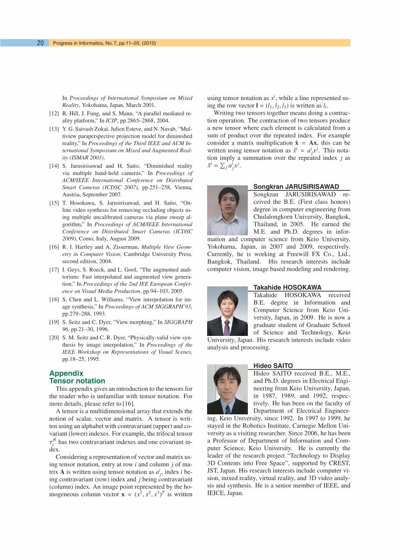
Songkran JARUSIRISAWADSongkran JARUSIRISAWAD re-ceived the B.E. (First class honors)degree in computer engineering fromChulalongkorn University, Bangkok,Thailand, in 2005. He earned theM.E. and Ph.D. degrees in infor-
mation and computer science from Keio University,Yokohama, Japan, in 2007 and 2009, respectively.Currently, he is working at Freewill FX Co., Ltd.,Bangkok, Thailand. His research interests includecomputer vision, image based modeling and rendering.
Takahide HOSOKAWATakahide HOSOKAWA receivedB.E. degree in Information andComputer Science from Keio Uni-versity, Japan, in 2009. He is now agraduate student of Graduate Schoolof Science and Technology, Keio
University, Japan. His research interests include videoanalysis and processing.
Hideo SAITOHideo SAITO received B.E., M.E.,and Ph.D. degrees in Electrical Engi-neering from Keio University, Japan,in 1987, 1989, and 1992, respec-tively. He has been on the faculty ofDepartment of Electrical Engineer-
ing, Keio University, since 1992. In 1997 to 1999, hestayed in the Robotics Institute, Carnegie Mellon Uni-versity as a visiting researcher. Since 2006, he has beena Professor of Department of Information and Com-puter Science, Keio University. He is currently theleader of the research project “Technology to Display3D Contents into Free Space”, supported by CREST,JST, Japan. His research interests include computer vi-sion, mixed reality, virtual reality, and 3D video analy-sis and synthesis. He is a senior member of IEEE, andIEICE, Japan.