Research on Six-axis Force Sensor for Fatigue Test of ...
7
2014 © The American Computational Science Society. All rights reserved. Journal of Computational Science & Engineering 10 (2014) 366-372 Journal of Computational Science & Engineering Available at http://www.asocse.org ISSN 1710-4068 Research on Six-axis Force Sensor for Fatigue Test of Large Structure 1 Yun Lu, 1 Weijia Li, 2 Wenzhuo Tian, 1 Kai Zhou 1 School of Naval Architecture and Ocean Engineering, Huazhong University of Science and Technology, Wuhan, 430074, Hubei China 2 Institute of China Shipbuilding Industry Corporation, Wuhan, 430074, Hubei China _____________________________________________________________________________________________ Corresponding author: [email protected] Article Information _______________________________________ Article history: Received 15 December 2013 Revised 20 January 2014 Accepted 22 January 2014 Available online 29 January 2014 _______________________________________ Keywords: Piezoelectric quartz Equivalent capacity compression Heavy force division Fatigue test Static calibration experiment _______________________________________ Abstract According to the requirements of fatigue test of aircraft cabin, large engine and mining machinery for heavy-duty six dimensional generalized force sensors, a new method of using piezoelectric quartz as force-sensitive element on the basis of the theory of heavy force division and equivalent capacity compression is proposed in this study. Furthermore, in order to minimize the force-coupling for the six-dimension force sensor, the optimization objective function is devised and the calculation method for decoupling is also proposed, on the basis of which, the generalized force sensor with high sensitivity, high stiffness, high linearity but light in its weight is designed. At last, the static calibration experiment is carried out. The result shows that the sensor has a good ability of heavy force division and capacity for equivalent compression. it can be well used in large tonnage six component force loading device and fatigue test system. 1. Introduction The Life prediction theory is not only the basic theory for structure security service of mechanical parts, but also an important aspect for modern mechanical design. Advanced life test has become a hot spot in the field of the fatigue test. It should be studied how to simulate the effect of environmental / medium to product life based on the traditional test scheme, and how to format reliable testing methods [1]. At present, six degree of freedom parallel mechanism has been widely used in flight simulator, the space docking simulation, driving simulation training, ship and vehicle movement simulation. Related theories and technology for six degree of freedom parallel mechanism have been ready, but most of them focus on the aspects of mechanism design, pose and inverse solution algorithm, kinematics, dynamics, error analysis and so on. Few studies have researched the output
Transcript of Research on Six-axis Force Sensor for Fatigue Test of ...

2014 © The American Computational Science Society. All rights reserved.
Journal of Computational Science & Engineering 10 (2014) 366-372
Journal of Computational Science & Engineering
Available at http://www.asocse.org ISSN 1710-4068 Research on Six-axis Force Sensor for Fatigue Test of Large Structure 1Yun Lu, 1Weijia Li, 2Wenzhuo Tian, 1Kai Zhou
1 School of Naval Architecture and Ocean Engineering, Huazhong University of Science and Technology, Wuhan, 430074, Hubei China 2 Institute of China Shipbuilding Industry Corporation, Wuhan, 430074, Hubei China _____________________________________________________________________________________________
Corresponding author: [email protected]
Article Information _______________________________________ Article history: Received 15 December 2013 Revised 20 January 2014 Accepted 22 January 2014 Available online 29 January 2014 _______________________________________ Keywords: Piezoelectric quartz Equivalent capacity compression Heavy force division Fatigue test Static calibration experiment _______________________________________
Abstract
According to the requirements of fatigue test of aircraft cabin, large engine and mining machinery for heavy-duty six dimensional generalized force sensors, a new method of using piezoelectric quartz as force-sensitive element on the basis of the theory of heavy force division and equivalent capacity compression is proposed in this study. Furthermore, in order to minimize the force-coupling for the six-dimension force sensor, the optimization objective function is devised and the calculation method for decoupling is also proposed, on the basis of which, the generalized force sensor with high sensitivity, high stiffness, high linearity but light in its weight is designed. At last, the static calibration experiment is carried out. The result shows that the sensor has a good ability of heavy force division and capacity for equivalent compression. it can be well used in large tonnage six component force loading device and fatigue test system.
1. Introduction The Life prediction theory is not only the basic
theory for structure security service of mechanical parts, but also an important aspect for modern mechanical design. Advanced life test has become a hot spot in the field of the fatigue test. It should be studied how to simulate the effect of environmental / medium to product life based on
the traditional test scheme, and how to format reliable testing methods [1].
At present, six degree of freedom parallel mechanism has been widely used in flight simulator, the space docking simulation, driving simulation training, ship and vehicle movement simulation. Related theories and technology for six degree of freedom parallel mechanism have been ready, but most of them focus on the aspects of mechanism design, pose and inverse solution algorithm, kinematics, dynamics, error analysis and so on. Few studies have researched the output

Lu et al. / Journal of Computational Science & Engineering 10 (2014) 366-372
2014 © The American Computational Science Society. All rights reserved.
367
force control for six degree of freedom parallel electro hydraulic servo mechanism, especially for the generalized force loading [2]. Some studies have realized the single degree servo control for six degree of freedom parallel mechanism, but the study of six dimensional generalized force loading is still in the stage of theoretical and simulation, there is still some gap from the actual engineering application.
In order to realize accurate loading for generalized force, detection technology for six dimensional generalized force is the key problem. The rated load of the large six degree of freedom test planet discussed in this paper has reached 1.0×10⁶N, rated load torque is up to 3.5×10⁶Nm, six axis force sensor for heavy load equipment will be the key problem [3]. Therefore, a novel parallel development of high precision, large tonnage force measuring platform has become the key technology in this research. The structure of sensitivity element for six axis force sensor determines the performance; the structure design is always a core problem in the research. The development of six axis force sensor has undergone the three vertical rib structure, four vertical rib structure, tubular structure, ring structure, the cross structure till the research hot spot at present -the six axis force sensor based on Stewart platform [4]. Six axis force / torque sensor mostly uses the strain gauge as the sensing element, but it is not suitable for dynamic measurement [5-7].
At present, heavy load sensors contain two main types, one is the supported type and the other is the attached type [8]. The bearing area, size, quality and price of supported sensor are significant increased with enlargement of its range. It is not convenient for engineering application, repairing and spare parts supplying. The attached type of heavy force sensor has the advantages of simple structure, convenient installation, but these two kinds of force sensors are belong to the single dimension measurement sensor.
Professor Li [9] has put forward a new kind of six dimensional sensors by using the piezoelectric quartz based on the theory of heavy force division,
which can meet the requirements of dynamic measurement in six dimensional space. This method provides a new idea for the design of the high performance large six dimensional generalized force measuring platform in this study.
2. Parallel force division principle and model for the sensor
In the present study, in order to implement the
dynamic measurement of the large space load on operating shaft, it is not feasible to load directly in the piezoelectric quartz group for the reason that the maximum bearing capacity of piezoelectric quartz is about 130N/mm2, even if the large size of piezoelectric quartz is used, which can bear the load limit of about 12.5t, it is hard to meet the requirements of the operating load of hundreds of tons from the giant machines. That is to say the direct load type is not advisable. The sensor should use the load division mechanism, to make it acceptable in the range of a direct effect on the force sensing element.
The measuring principle of parallel force division is similar to the principle of DC high current shunt measurement, as is shown in Figure 1 (a). The elastic model of heavy load division is shown in Figure 1 (b).
Fig. 1 (a) Model of current division

Lu et al. / Journal of Computational Science & Engineering 10 (2014) 366-372
2014 © The American Computational Science Society. All rights reserved.
368
Fig. 1 (b) Model of heavy load division
It is not feasible to use galvanometer directly to measure large DC current. The current division principle is used to solve the problem, which shows that the algebraic sum of currents in a network of conductors meeting at a point is zero. According to this principle, it can be described as:
21 2
1
RI IR
(1)
22
1
1RI IR
(2)
When 1 2R R , it can be described that:
22 2
1r
RI I C IR
(3)
Similarly, parallel force division principle for heavy load measurement is realized due to the stiffness force distribution principles of parallel mechanism. It is described as following:
1 2 11 2
1 2 2
,F F kF Fk k k
(4)
12 2
2
11r
kF F Fk C
(5)
2 2
1 1 2
2
1
1r
F kC kF k kk
(6)
Where 1k represents the stiffness of parallel mechanism and 2k represents the stiffness of force-sensitive element. rC is defined as the load division ratio of the load measurement mechanism, that is, the ratio of load on force sensitive element in total load. The parameter rC reflects the
capacity of load division. The load sharing capability is better when the value of rC is smaller, worse when rC is bigger.
Piezoelectric quartz force sensor is mainly based on the piezoelectric effect; various cutting types of piezoelectric quartz that is sensitive to different directions of load can be designed according to the piezoelectric quartz matrix. X0°
types which are sensitive to longitudinal load and Y0° types which are sensitive to shear loading are most commonly used. In order to improve the sensitivity of piezoelectric sensors and simplifies the structure, it is generally designed with two chips of same cutting type to form a crystal group, then a certain structure of a sensor is decided by assembling several crystal groups mentioned above. The basic model for the sensor is shown in Figure 2:
Fig. 2 Model of sensor
3. Mechanics model and optimization objective function
There are five major assumptions. Assumption 1. The sensor is rigid; piezoelectric
quartz crystal groups are elastomer with the same stiffness and sensitivity.
Assumption 2. The force that is perpendicular to the sensor surface is dis tributed to the

Lu et al. / Journal of Computational Science & Engineering 10 (2014) 366-372
2014 © The American Computational Science Society. All rights reserved.
369
piezoelectric quartz crystal groups according to the lever balance principle.
Assumption 3. The force that is parallel to the sensor surface is distributed to the piezoelectric quartz crystal groups according to the lever balance principle when the line of related crystal groups is perpendicular to the force. It is evenly distributed to the piezoelectric quartz crystal groups when the line of related crystal groups is parallel to the force.
Assumption 4. The torque which is parallel to the sensor surface is evenly distributed to the each piezoelectric quartz crystal group and translates into forces of different directions. Assumption 5. The torque which is perpendicular to the sensor surface will change the vertical force of piezoelectric quartz crystal groups.
Under these assumptions, Cartesian coordinate is established on the crystal plane of these four piezoelectric quartz crystal groups which is shown in Figure 3:
Fig. 3 Cartesian coordinates on mechanics model Optimization objective function
Because of the linear relationship of electric
power and force according to the piezoelectric effect and the relative independence of
tri-direction-force transducer in measurement, the output signal is following the principle of linear superposition and also following the theorem about translation of a force. The external force is noted as F and can be decomposed into tri-direction normal force noted as xF , yF , zF , and the same for the torque xM , xM , zM . As in Fig.3, Therefore, if the sensor is only acted upon by xF , it can be described that:
1 2 3 414x x x x xF F F F F (7)
If the sensor is only acted upon by yFyF
it has:
1 2 3 414y y y y yF F F F F (8)
If the sensor is only acted upon by zFyF
it has:
1 2 3 414z z z z zF F F F F (9)
If the sensor is only acted upon by xMyF
it has:
2 41 1,2 2z x z xF M F M
a a (10)
Where a is a parameter which is reflected by the size of sensor, if the sensor is only acted upon by
yMyF
it has:
1 3
1 1,2 2z y z yF M F M
a a (11)
If the sensor is only acted upon by zMyF
it has:
1 2
3 4
1 1,4 4
1 1,4 4
y z x z
y z x z
F M F Ma a
F M F Ma a
(12)
According to the principle of linear superposition and theorem about translation of a force, it can be described as following:
1 1
1
1 1 1,4 4 41 14 2
x x y y z
z z y
F F F F Ma
F F Ma
(13)
2 2
2
1 1 1,4 4 41 14 2
x x z y y
z z x
F F M F Fa
F F Ma
(14)

Lu et al. / Journal of Computational Science & Engineering 10 (2014) 366-372
2014 © The American Computational Science Society. All rights reserved.
370
3 3
3
1 1 1,4 4 41 14 2
x x y y z
z z y
F F F F Ma
F F Ma
(15)
4 4
4
1 1 1,4 4 41 14 2
x x z y y
z z y
F F M F Fa
F F Ma
(16)
Therefore, the optimization objective function can be concluded as:
1 2 3 4
1 2 3 4
1 2 3 4
2 4
3 1
1 2 4 2
x x x x x
y y y y y
z z z z z
x z z
y z z
z y y x x
F F F F FF F F F F
F F F F FM aF aFM aF aF
M a F F F F
(17)
4. Static calibration experiment
Many kinds of loading plans have taken into comparison comprehensively. Ultimately the loading calibration of six-axis force sensor was completed by using the large hydraulic loading system. In the process of the calibration of six-axis force sensor, it is required to apply the space six-axis force that is the four circularly symmetric points on the upper platform. Every point has five directions. Totally twenty directions are required to apply load. According to the linear algebra, if the impact of nonlinear factors is not taken into consideration, the unique solution of equation system that contains 36 unknown variables in the 36 equations can be achieved with the corresponding measured output voltage signal vector of six sensors under the sensor 6 linearly independent load force vector. However, the nonlinear effects certainly exist. And the accuracy of the sensor is impacted largely. The accurate calibration results cannot always be achieved by just loading the six linearly independent force vector to calculate the calibration matrix. Increasing the number of calibration is the most
convenient and effective way to solve the nonlinear effects on the calibration matrix. And the full-scale area of the entire system is required to be covered by calibration points. It means that the full-scale range in each force direction that is calibrated redundantly is divided into a number of equally spaced calibration points. So in this way non-linear effects of the system will be effectively reduced. The steps for the static calibration experiment are as following:
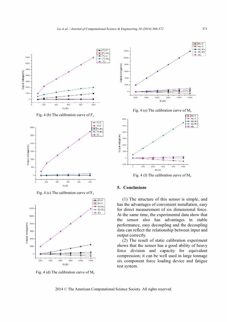
The range is 0-1000N, interval is 200N. Continuous force is loaded to the sensor three times through the standard force loading device, the output voltage value corresponding to the standard input force and the related input-output data is recorded. The necessary processing is done with the testing data and the linear relation between input power and output voltage is fitted on the basis of the least square method. Finally, linearity, sensitivity and repetition are obtained according to the experimental data and the fitting line. The result is shown in Figure 4:
Fig. 4 (a) The calibration curve of Fx
Lu et al. / Journal of Computational Science & Engineering 10 (2014) 366-372
2014 © The American Computational Science Society. All rights reserved.
371
Fig. 4 (b) The calibration curve of Fy
Fig. 4 (c) The calibration curve of Fz
Fig. 4 (d) The calibration curve of Mx
Fig. 4 (e) The calibration curve of My
Fig. 4 (f) The calibration curve of Mz
5. Conclusions (1) The structure of this sensor is simple, and
has the advantages of convenient installation, easy for direct measurement of six dimensional force. At the same time, the experimental data show that the sensor also has advantages in stable performance, easy decoupling and the decoupling data can reflect the relationship between input and output correctly.
(2) The result of static calibration experiment shows that the sensor has a good ability of heavy force division and capacity for equivalent compression; it can be well used in large tonnage six component force loading device and fatigue test system.

Lu et al. / Journal of Computational Science & Engineering 10 (2014) 366-372 372
2014 © The American Computational Science Society. All rights reserved.
Acknowledgement
The research described within this paper was done mostly within the support by Fundamental Research Funds for the Central Universities Grant #0118140031 to Weijia Li and Grant #0118140032 to Yaozhong Wu. This work involved three partners, two within the Huazhong University of Science and Technology (HUST), namely, Laboratory for Six DOF. Simulation and the School of Naval Architecture and Ocean Engineering (SNAOE), and one within NO.722 Institute of China Shipbuilding Industry Corporation, which provided measurement data of, and process knowledge about, static calibration experiment.
References
[1] Y.H. Zhang, Northwestern Polytechnical University, (2007), in Chinese.
[2] J. Wu, Zhejiang University, (2006), in Chinese. [3] T.Z. Zhao, Yanshan University, (2009), in Chinese. [4] T.A. Dwarakanath, B. Dasgupta, and T.S.
Mruthyunjaya, Mechatronics, 11 (2001) 793-809. [5] R. Ranganath, P.S. Nair, T.S. Mruthyunjaya, and A.
Ghosal, Mechanism and Machine Theory, 39 (2004) 971-998.
[6] L. Tao, Y. Inoue, K. Shibata, Y. Yamasaki, and M. Nakahama, Proceedings of 2004 IEEE Conference on Robotics, Automation and Mechatronics, Singapore, 1 (2004) 208-212.
[7] N. Krouglicof, L.M. Alonso, and W.D. Keat, Proceedings of 2004 IEEE International Conference on Systems, Man and Cybernetics, Hague, Netherlands, 5 (2004) 4426-4431.
[8] M. Gavaises, D. Papoulias, A. Andriotis, SAE Paper (2007) 2007-01-0246.
[9] Y.M. Li, Q.S. Xu, Mechanism and Machine Theory, 43 (2008) 186-200.