RESEARCH ON BLADE SHAPE OPTIMIZATION OF MULTISTAGE ...
12
1 Copyright © 2015 by ISABE ISABE-2015-20085 RESEARCH ON BLADE SHAPE OPTIMIZATION OF MULTISTAGE COMPRESSOR USING ADJOINT METHOD WITH STATIC PRESSURE CONSTRAINT AT BLADE ROW INTERFACE Jia YU, Lucheng JI, Weiwei LI* and Weilin YI Beijing Institute of Technology, Beijing, China Email: * [email protected] Abstract Adjoint method presents an important way for designing refinement of multistage compressors. However, it often gives useless designs for engineering practice because the operation condition drifted during the optimization procedure. Therefore, based on the previous development work of multistage turbomachinery blades optimization design using adjoint method and thin shear-layer N-S equations, in which the entropy production is selected as the objective function with given mass flow rate and total pressure ratio as imposed constraints, the present paper introduce a new constraint, that is the radial static pressure distribution at the interfaces between rows is imposed. The approach is applied to the redesign of 5-stage supersonic compressor with and without the radial static pressure distribution constraint (RSPDC) at the interfaces between rows. The results demonstrate that without the constraint the operation condition drifted during optimization procedure. However, the redesign with the constraint successfully keeps the radial static pressure distribution at the interfaces between rows and don’t compromise the optimization. Introduction The adjoint method has been applied extensively to external flow problems over the last twenty years [1-9]. More recently, it has also been applied to turbomachinery blade aerodynamic shape design [10-21]. The adjoint method used for gradient calculations has low computational cost, independent of the number of design variables involved. The gradient is calculated indirectly by solving an adjoint system, all sensitivity derivatives are thus obtained with the cost of one flow solution and one adjoint solution for each function. Hence, the total computing cost in one design cycle is roughly equivalent to twice the cost of the iteration of the flow equations. This high
Transcript of RESEARCH ON BLADE SHAPE OPTIMIZATION OF MULTISTAGE ...

1 Copyright © 2015 by ISABE
ISABE-2015-20085
RESEARCH ON BLADE SHAPE OPTIMIZATION OF MULTISTAGE COMPRESSOR USING ADJOINT METHOD WITH STATIC PRESSURE
CONSTRAINT AT BLADE ROW INTERFACE
Jia YU, Lucheng JI, Weiwei LI* and Weilin YI
Beijing Institute of Technology, Beijing, China
Email: * [email protected]
Abstract
Adjoint method presents an important way for designing refinement of multistage compressors.
However, it often gives useless designs for engineering practice because the operation condition
drifted during the optimization procedure. Therefore, based on the previous development work of
multistage turbomachinery blades optimization design using adjoint method and thin shear-layer
N-S equations, in which the entropy production is selected as the objective function with given
mass flow rate and total pressure ratio as imposed constraints, the present paper introduce a new
constraint, that is the radial static pressure distribution at the interfaces between rows is imposed.
The approach is applied to the redesign of 5-stage supersonic compressor with and without the
radial static pressure distribution constraint (RSPDC) at the interfaces between rows. The results
demonstrate that without the constraint the operation condition drifted during optimization
procedure. However, the redesign with the constraint successfully keeps the radial static pressure
distribution at the interfaces between rows and don’t compromise the optimization.
Introduction The adjoint method has been applied extensively to external flow problems over the last twenty
years [1-9]. More recently, it has also been applied to turbomachinery blade aerodynamic shape
design [10-21]. The adjoint method used for gradient calculations has low computational cost,
independent of the number of design variables involved. The gradient is calculated indirectly by
solving an adjoint system, all sensitivity derivatives are thus obtained with the cost of one flow
solution and one adjoint solution for each function. Hence, the total computing cost in one design
cycle is roughly equivalent to twice the cost of the iteration of the flow equations. This high

2 Copyright © 2015 by ISABE
computing efficiency makes adjoint method very promising for sensitivity analysis and design
optimization, especially when the shape optimization problem has a large number of design
variables.
During the redesign process, it is vital to keep the original parameters consistent with the
performance requirements. However, the adjoint method often gives undesired designs for
engineering applications as the radial static pressure distribution deviates during the optimization
procedure. As it shown in Figure 1, the static pressure at the exit of rotor is increased during the
optimization procedure, changing the radial distribution of the original design. To address the issue
of the radial static pressure distribution limitation, and fix the rotor working condition, the radial
static pressure distribution is considered in this paper as an additional constraint. Emphasis is placed
on implementing this constraint on the radial static pressure distribution at mixing plane as a
penalty function, and an adjoint mixing plane treatment involving the impact of the radial static
pressure distribution constraint (RSPDC) in a multi-stage environment is developed.
Figure 1 Spanwise distribution of static pressure at the exit of rotor
Optimization Problem Governing equations
In viscous calculation, the boundary layer effects determine the secondary flow and the losses,
so the wall boundary must be simulated correctly [22] and the real-life formation of viscous term
may not be a key concern at locations far away from wall. The thin sheared-layer RANS equations
in cylindrical-coordinate system (see Eq. (1)) were using explicit finite volume method in this paper.
Viscous body forces to model viscous effects are calculated from the thin shear-layer approximation
and a wall function proposed by Denton [23]. The space discretization uses the Scree scheme [24]
with all the flow variables stored at the grid cell corners. A blend artificial dissipation method of
3 Copyright © 2015 by ISABE
second and forth order stabilizes the numerical iteration and identifies shock flows. The steady-state
simulation is launched form an initial guess of flow field using time-marching method. A spatially
varied time steps and three-level multigrid accelerate the numerical convergence. The algebraic
eddy-viscosity model is supplemented for turbulence closure. The 3D thin shear-layer
Navier-Stokes equation in a cylindrical coordinate system is given by,
( ) ( )0V Vr F F G U r GU E S
t x r r rωθ
∂ − ∂ − −∂ ∂ + + + − =∂ ∂ ∂ ∂
(1)
Where ,E F and G are flow fluxes; S is source term; VF and VG are streamwise and bladewise flow
viscous fluxes;
0T
x rV
V V VVF r rr r r r
θ θµ µ µ ω µ∂ ∂ ∂∂ = ∂ ∂ ∂ ∂
; 0T
x rV
V V VVG r rr r r r
θ θµ µ µ ω µθ θ θ θ
∂ ∂ ∂∂ = ∂ ∂ ∂ ∂
Objective and constraints In general, the increase of aerodynamic efficiency is obtained by means of minimizing the
entropy production rate. In this paper, the net mass-averaged entropy production rate from the
domain inlet to the domain outlet is chosen as the main objective and the constraints are set to limit
the variation of mass flow rate, pressure ratio and the radial static pressure distribution changes to
be less than 0.5% of the datum. The final compounded objective is defined by the summation of the
main objective and the three aforementioned constraints, as it is shown in Eq. (2),
( )
2
2 2init1
1 2 3 2init initinit init
1 init
11 1
1
MP
MP
p dsps mI
s m p dsp
πσ σ σπ
− ∆ = + − + − + ∆ −
∫∫
∫∫
(2)
Where the m represents inlet and outlet average mass flow rate, β represents outlet flow angle.
The definition for the entropy generation rate s∆ in the above expression is given by,
* *1 1
* *
out in
out in
T Tu ds u dsP P
suds uds
γ γγ γ
ρ ρ
ρ ρ
− −
∆ = −∫∫ ∫∫
∫∫ ∫∫
The subscript “init” denotes initial values, initp is the baseline average pressure along the whole
upstream side face of the mixing plane. And the subscript “ 1MP ” denotes upstream side face of the
mixing plane. 1 2,σ σ and 3σ are weighting factors taking different values for the following five-stage
axial compressor blade design: 1 2 3250, 200, 1000.σ σ σ= = = For the design case without RSPDC,
the value of the 3σ weighting factor should be set to zero. Different values of 1 2,σ σ and 3σ will
usually lead to different designs, as it is also indicated in [25]. A good choice of these values
usually needs some trial and error.

4 Copyright © 2015 by ISABE
Adjoint method The objective function I is a function of flow variable vector U and design variableα ,
expressed as follows,
( , )I I U α= (3)
Where ( ), , , , ,U u v w eρ ρ ρ ρ ρ= ( )1 2, , , ,nα α α α= and n denotes the design number.
Flow variable and the design variable are related through the flow equation,
( , ) 0N U α = (4)
The optimization problem can be expressed as,
Min ( , )I U α s.t. ( , ) 0N U α =
The ultimate gradient is just a combined post-process of the flow field and the adjoint field,
TdI I Nd
λα α α
∂ ∂= −∂ ∂
(5)
This is the simplest interpretation of the adjoint method that is widely used. Its detailed
derivation is complex because the steady Reynolds Averaged Navier-Stokes (RANS) equations are
three dimensional, and include turbulence, viscosity, nonlinearity, and the specifications of flow
boundary conditions.
Adjoint equations The direct gradients of the above objective with respect to the design variables are expressed in
a boundary area-integral form,
( )* *1 12* *
1 1 1 2 2 2 0* *1
+
+IN OUT MP
dI I U Id U
T Tu p ds u p ds p p dsP p
γ γγ γ
α α α
ρ β ξ ϕ ρ β ξ ϕ ϑ− −
′∂ ∂ ∂= ×
′∂ ∂ ∂
≈ + + + + + −
∫∫ ∫∫ ∫∫ (6)
The symbols 1 1 1 2 2 2, , , , , ,β ξ ψ β ξ ψ ϑ are constant coefficients, and once a convergent solution of flow
field is obtained, they are determined by U ′ at the inlet, outlet and mixing plane,
where ( ), , , , .U p u v w T′ = The subscripts “1” and “2” represent inlet and exit.
Then the adjoint equation can be expressed as,
( )1 0T
TT T T T r HrHA B C D Px r r r r r
θλ λ λ λθ θ
− ∂∂∂ ∂ ∂ + + + + + = ∂ ∂ ∂ ∂ ∂ (7)
Details of these adjoint boundary conditions were similarly discussed in reference [18] and will
not be repeated here.

5 Copyright © 2015 by ISABE
Adjoint mixing plane To extend the adjoint-based gradient calculation into multiple blade rows, a reasonable adjoint
mixing plane is required to circumvent the adjoint connections while satisfying the adjoint
conservative requirement. The effect of introducing adjoint mixing plane is equivalent to produce
another two extra area integrals along both side faces of the mixing plane.
( )( ) 20
1 2
=0T Tn n
MP MP
Q p p ds Q dsλ ϑ λ− − −∫∫ ∫∫ (8)
The two integrals in Eq. (8) count in total areas of all annular passages for each row. This can
be reduced in one blade passage by circumferential averaging,
( )( ) 20
1 21 2
1 1 0T Tn n
MP MP
Q p p rd Q rdPL PL
λ ϑ θ λ θ− − − =∫ ∫ (9)
Where 1PL and 2PL are the pitch lengths at both side faces of mixing plane.
Reference [13] gives a rational reduction to Eq. (9). The derivation is based on the assumption
of: (I) the mixing plane is perpendicular to the axial direction; (II) the adjoint variables are
independent of a design variable in the mixing plane; and (III) the perturbations of the design
variables of the blade geometry model do not change the outline and grid points of the two side
faces. Then, Eq. (9) can be further reduced to
( )20
1 21 2
1 1 ( )T T
MP MPRPD Impact
E p p rd Erd MPL PL
λ ϑ θ λ θ λ − − − =
∫ ∫ (10)
Where the function ( )M λ only depends on the adjoint variables, and in reference [13] it is set to
zero.
Optimization setup In every design cycle, the initial values of design variables are set to zero by default and this
means no perturbations. Once the ultimate gradient evaluation is finished, the steepest descent
method is employed to calculate the values of all design variables,
1l ll
dId
α α εα
+ − = − (11)
Where l represents design cycle counter. ε is a relative constant step size.
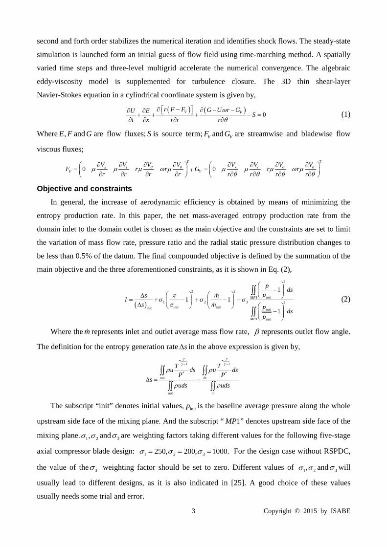
Results and Discussions A five-stage axial compressor with inlet guide vane under supersonic flow condition is selected
as the present study case used for detailed refinement design, as shown in Figure 2. The design
pressure ratio of the five-stage axial compressor is 6.5 at a mass flow rate of 5.1kg/s. The design
rotational speed is 44700 rpm with tip speed less than 475 m/s, and the gap of the rotor and stator is
6 Copyright © 2015 by ISABE
0.25mm.
Figure 2 Meridional view of five-stage axial compressor
Case I The first stage of a five-stage axial compressor with inlet guide vane is a supersonic stage and
is selected as the present study case used for detailed refinement design. The configuration of
baseline blade geometry model (see Fig. 3) and its aerodynamic parameters in this paper are
obtained from the preliminary design.
Figure 3 Configuration and grid system
In this Case, the rotor and stator is redesigned with and without the radial static pressure
distribution constraint (RSPDC) respectively. The optimized design without the RSPDC was named
as constrained I, and the optimized design with the RSPDC was named as constrained II. The
performance comparison among the original compressor, constrained I and constrained II at the
peak efficiency point is listed in Table 1. As is shows, the adiabatic efficiency has 1.6%
improvements both in constraint I and constraint II, while the total pressure ratio and mass flow rate
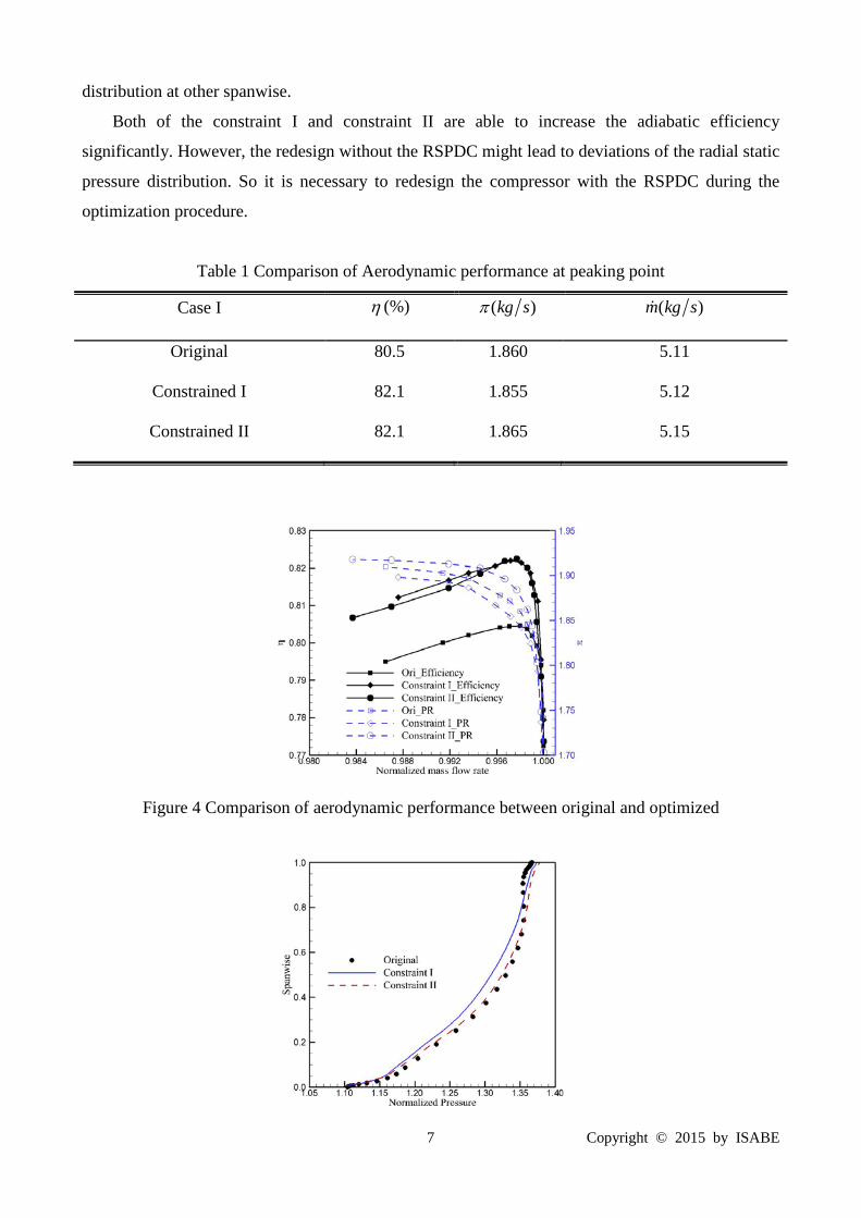
changed a little. Figure 4 compares the computed total pressure ratio and adiabatic efficiency versus
the normalized mass flow rate through the compressor. The mass flow rate in the figure is
normalized by its choke value. Both of the constrained I and II have improved the adiabatic
efficiency significantly. The difference is that the margin of mass flow in constraint I was reduced,
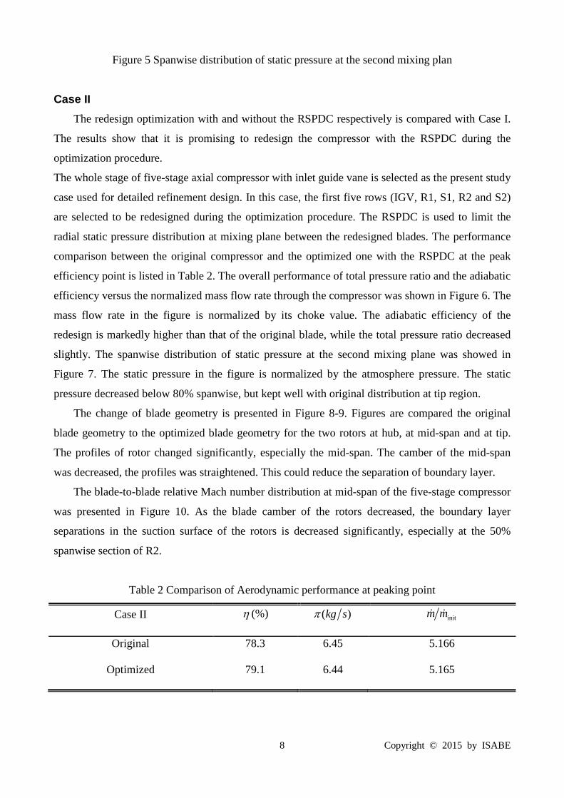
but increased in constraint II. Figure 5 presents the spanwise distributions of static pressure at the
second mixing plane. The static pressure in the figure is normalized by the atmosphere pressure. In
constraint I, the static pressure decreased at 10%-80% span, but increased at tip region. Though the
static pressure increased slightly at tip region in constraint II, it matched well with original
7 Copyright © 2015 by ISABE
distribution at other spanwise.
Both of the constraint I and constraint II are able to increase the adiabatic efficiency
significantly. However, the redesign without the RSPDC might lead to deviations of the radial static
pressure distribution. So it is necessary to redesign the compressor with the RSPDC during the
optimization procedure.
Table 1 Comparison of Aerodynamic performance at peaking point
Case I η (%) ( )kg sπ ( )m kg s
Original 80.5 1.860 5.11
Constrained I 82.1 1.855 5.12
Constrained II 82.1 1.865 5.15
Figure 4 Comparison of aerodynamic performance between original and optimized
8 Copyright © 2015 by ISABE
Figure 5 Spanwise distribution of static pressure at the second mixing plan
Case II The redesign optimization with and without the RSPDC respectively is compared with Case I.
The results show that it is promising to redesign the compressor with the RSPDC during the
optimization procedure.
The whole stage of five-stage axial compressor with inlet guide vane is selected as the present study
case used for detailed refinement design. In this case, the first five rows (IGV, R1, S1, R2 and S2)
are selected to be redesigned during the optimization procedure. The RSPDC is used to limit the
radial static pressure distribution at mixing plane between the redesigned blades. The performance
comparison between the original compressor and the optimized one with the RSPDC at the peak
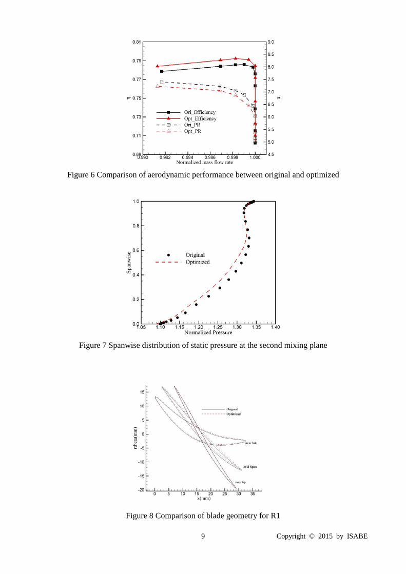
efficiency point is listed in Table 2. The overall performance of total pressure ratio and the adiabatic
efficiency versus the normalized mass flow rate through the compressor was shown in Figure 6. The
mass flow rate in the figure is normalized by its choke value. The adiabatic efficiency of the
redesign is markedly higher than that of the original blade, while the total pressure ratio decreased
slightly. The spanwise distribution of static pressure at the second mixing plane was showed in
Figure 7. The static pressure in the figure is normalized by the atmosphere pressure. The static
pressure decreased below 80% spanwise, but kept well with original distribution at tip region.
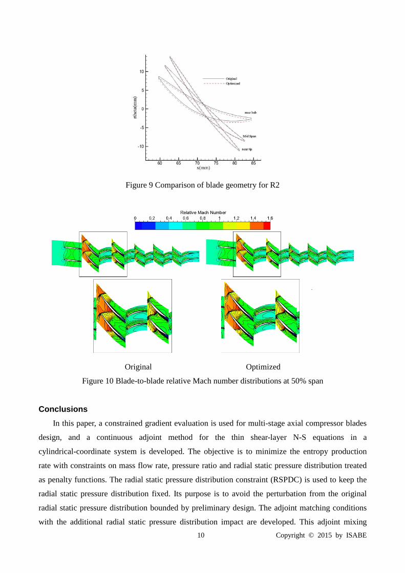
The change of blade geometry is presented in Figure 8-9. Figures are compared the original
blade geometry to the optimized blade geometry for the two rotors at hub, at mid-span and at tip.
The profiles of rotor changed significantly, especially the mid-span. The camber of the mid-span
was decreased, the profiles was straightened. This could reduce the separation of boundary layer.
The blade-to-blade relative Mach number distribution at mid-span of the five-stage compressor
was presented in Figure 10. As the blade camber of the rotors decreased, the boundary layer
separations in the suction surface of the rotors is decreased significantly, especially at the 50%
spanwise section of R2.
Table 2 Comparison of Aerodynamic performance at peaking point
Case II η (%) ( )kg sπ initm m
Original 78.3 6.45 5.166
Optimized 79.1 6.44 5.165
9 Copyright © 2015 by ISABE
Figure 6 Comparison of aerodynamic performance between original and optimized
Figure 7 Spanwise distribution of static pressure at the second mixing plane
Figure 8 Comparison of blade geometry for R1
10 Copyright © 2015 by ISABE
Figure 9 Comparison of blade geometry for R2
Original Optimized
Figure 10 Blade-to-blade relative Mach number distributions at 50% span
Conclusions In this paper, a constrained gradient evaluation is used for multi-stage axial compressor blades
design, and a continuous adjoint method for the thin shear-layer N-S equations in a
cylindrical-coordinate system is developed. The objective is to minimize the entropy production
rate with constraints on mass flow rate, pressure ratio and radial static pressure distribution treated
as penalty functions. The radial static pressure distribution constraint (RSPDC) is used to keep the
radial static pressure distribution fixed. Its purpose is to avoid the perturbation from the original
radial static pressure distribution bounded by preliminary design. The adjoint matching conditions
with the additional radial static pressure distribution impact are developed. This adjoint mixing
11 Copyright © 2015 by ISABE
plane and its non-reflective treatment extends the gradient evaluations into a multi-stage
environment for blade rows aerodynamic matching design.
With the adjoint-based gradient evaluation, the steepest descent method, an efficient integrated
shape optimization loop is constructed, and it is applied to the performance-improvement redesign
of a five-stage axial compressor. The RSPDC addressed the issue of the radial static pressure
distribution limitation, and stabilizes the rotor working condition at peak point. Then it further
explores the peak aerodynamic potential. The redesign with the constraint can successfully keep the
radial static pressure distribution at the interfaces between rows and don’t compromise the
optimization. This clearly indicates that the constraint on the radial static pressure distribution is
very promising.
Acknowledgments The authors would like to express their deep appreciations to the National Natural Science
Foundation of China for funding this work, Project No. 51176012.
References [1] Jameson, A., 1988, “Aerodynamic Design via Control Theory,” Journal of Scientific Computing,
3(3):233-260. [2] Jameson, A., 1995, “Optimum Aerodynamic Design using CFD and Control Theory,” AIAA 95-1729-CP. [3] Jameson, A., 2003, “Aerodynamic Shape Optimization using the Adjoint Method,” Lectures at the Von
Karman Institute, Brussels. [4] Reuther, J., Jameson, A., 1994, “Control Based Airfoil Design using the Euler Equations,” AIAA Paper
94-4272-CP. [5] Reuther, J., Jameson, A., 1995, “Aerodynamic Shape Optimization of Wing and Wing-body Configurations
using Control Theory,” AIAA Paper 95-0123-CP. [6] Reuther, J., Jameson, A., 1997, “Constrained Multipoint Aerodynamic Shape Optimization using an Adjoint
Formulation and Parallel Computers,” AIAA Paper 97-0103. [7] Giles, M.B., Pierce, N.A., 1997, “Adjoint Equations in CFD: Duality, Boundary Conditions and Solution
Behavior,” AIAA Paper 97-1850. [8] Giles, M.B., Pierce, N.A., 1998, “On the Properties of Solutions of the Adjoint Euler Equations,” Numerical
Methods for Fluid Dynamics VI.ICFD pp. 1-16. [9] Giles, M.B., Duta, M.C., Muller, J.D, Pierce, N.A., 2003, “Algorithm Developments for Discrete Adjoint
Methods,” AIAA Journal, Vol. 41, No. 2. [10] Nielsen, E.J., Anderson, W.K., 1998, “Aerodynamic Design Optimization on Unstructured Meshes Using the
Navier-Stokes Equations,” AIAA Paper 98-4809. [11] Papadimitriou, D.I., Giannakoglou, K.C., 2006, “Compressor Blade Optimization Using A Continuous
Adjoint Formulation,” ASME Paper GT2006-90466. [12] Duta, M.C., Shahpar, S., Giles, M.B., 2007, “Turbomachinery Design Optimization Using Automatic
Differentiated Adjoint Code,” ASME Paper GT 2007-28329. [13] Wang, D.X., and He, L., 2008, “Adjoint Aerodynamic Design Optimization for Blades in Multi-stage
Turbo-machines: Part I- Methodology and Verification,” ASME Paper, GT2008-50208. [14] Wang, D.X., and He, L., 2008, “Adjoint Aerodynamic Design Optimization for Blades in Multi-stage
Turbo-machines: Part II- Validation and Application,” ASME Paper, GT2008-50209. [15] Frey, C., et al. 2009, “The Discrete Adjoint of A Turbomachinery RANS Solver,” ASME Paper,
GT2009-59062. [16] Walther, B., Nadarajah, S., 2012, “Constrained Adjoint-Based Aerodynamic Shape Optimization of A
Single-Stage Transonic Compressor,” ASME Paper, GT2012-69128. [17] Li, W.W., Tian, Y., Yi, W.L., Ji, L.C., Shao, W.W., and Xiao, Y. H., 2011, “Study on Adjoint-Based

12 Copyright © 2015 by ISABE
Optimization Method for Multi-Stage Turbomachinery,” Journal of Thermal Science, Vol. 20, No. 5, pp. 398-405.
[18] Ji, L.C., Li, W.W., Tian, Y., Yi, W.L., and Chen, J., 2012, “Multi-Stage Turbomachinery Blades Optimization Design using Adjoint Method and Thin Shear-Layer N-S Equations,” ASME Paper GT2012-68537.
[19] Shahpar, S., Caloni, S., 2013, “Adjoint Optimisation of a High-Pressure Turbine Stage for a Lean-burn Combustion System”, Proceeding of 10th ETC, Lappeenranta, Finland, April 2013.
[20] Luo, J.Q., Liu, F., Zhou, C., 2013, “Multi-point Design Optimization of A Transonic Compressor Blade by Using An Adjoint Method,” ASME Paper, GT2013-95155.
[21] Li, W.W., Yi, W.L., Ji, L.C., et al. 2010, “Research on Adjoint Method Applied to Compressor Aerodynamic Optimization”, Chinese Society Engineering Thermophysics Paper, No. 102005.
[22] Pieringer, P., Gottlich, E., Woisetschlager, J., Sanz, W., and Heitmeir, F., 2005, “Numerical Investigation of the Unsteady Flow through a Transonic Turbine Stage,” Proc. 6th European Conference on Turbomachinery, Lille, pp. 339-352.
[23] Denton, J.D., 1992, “The Calculation of Three-Dimensional Viscous Flow through Multistage Turbomachines,” Journal of Turbomachinery, Vol. 114, pp. 18-26.
[24] Denton, J.D., 2002, “The Effects of Lean and Sweep on Transonic Fan Performance: A Computational Study,” TASK Quart, pp. 7-23.
[25] Wu, H., Liu, F., and Tsai, H., 2005, “Aerodynamic design of turbine blades using an adjoint equation method,” AIAA Paper, 05-1006.


![Stator design by CFturbo® · 2020. 11. 12. · Blade setu p Blade shape Number of spans O Blade angles s [mm] Velocity Values aaLE Meridian Hu b Shroud cu [m/sl 21 s 195 175 Iss](https://static.fdocuments.in/doc/165x107/609b0ad23da8530227248392/stator-design-by-cfturbo-2020-11-12-blade-setu-p-blade-shape-number-of-spans.jpg)