
Design of intermediate die shape of multistage profile...
6
Journal of Mechanical Science and Technology 24 (12) (2010) 2539~2544 www.springerlink.com/content/1738-494x DOI 10.1007/s12206-010-0630-y Design of intermediate die shape of multistage profile drawing for linear motion guide † Sang-Kon Lee 1 , Jae-Eun Lee 2 , Sung-Min Kim 2 and Byung-Min Kim 3,* 1 PNU-IFAM JRC, Pusan National University, Busan, 609-735, Korea 2 Grauate School of Mechanical Engineering, Pusan National University, Busan, 609-735, Korea 3 School of Mechanical Engineering, Pusan National University, Busan, 609-735, Korea (Manuscript Received Spetember 29, 2009; Revised August 4, 2010; Accepted August 8, 2010) ---------------------------------------------------------------------------------------------------------------------------------------------------------------------------------------------------------------------------------------------------------------------------------------------- Abstract The design of an intermediate die shape is very important in multistage profile drawing. In this study, two design methods for the in- termediate die shape of a multistage profile drawing for producing a linear motion guide (LM) guide is proposed. One is the electric field analysis method using the equipotential lines generated by electric field analysis, and the other is the virtual die method using a virtual drawing die constructed from the initial material and the final product shape. In order to design the intermediate die shapes of a multi- stage profile drawing for producing LM guide, the proposed design methods are applied, and then FE analysis and profile drawing ex- periment are performed. As a result, based on the measurement of dimensional accuracy, it can be known that the intermediate die shape can be designed effectively. Keywords: Multistage profile drawing; Linear motion guide; Intermediate die; Electric filed analysis; Virtual die method ---------------------------------------------------------------------------------------------------------------------------------------------------------------------------------------------------------------------------------------------------------------------------------------------- 1. Introduction A linear motion (LM) guide is an important and effective machine part in a linear motion system because the high preci- sion positioning, automation, and energy savings are depends on the qualities of the LM guide [1]. LM guides are widely used in general machines, industrial robots, machine tools, electric devices, and semiconductor manufacturing devices. As shown in Fig. 1, a linear motion guide is a long rail with a constant irregular cross-sectional shape. Because the precision of a linear motion system depends mainly on a linear motion guide, high dimensional accuracy with small amounts of bending and torsion are required. LM guide is manufactured using the multistage profile drawing process. Profile drawing is the most effective method to fabricate profiles with irregular constant cross-sectional shapes. This process allows excellent surface finishes and closely controlled dimensions to be ob- tained in long products [2]. Moreover, unlike alternative ma- chining processes, this process minimizes the waste of mate- rial and improves mechanical properties by strain-hardening [3]. However, the advantages are often reduced because of the high cost of drawing dies and the labor-intensive task of proc- ess design. In multistage profile drawing, it is essential to de- sign the proper intermediate die shape in order to produce a sound product. Several studies have been carried out about the profile drawing process [2-13]. Until now, studies of the design of intermediate die shapes for multistage profile drawing have not been sufficient, and the design of the intermediate die shape has been done in an intuitive way based upon the ex- perience of industrial experts. In this study, two methods are proposed in order to design the intermediate die shape of a multistage profile drawing for producing a LM guide: the electric field analysis method, and the virtual die method. The designed intermediate die shapes based on the proposed methods are compared with an actual operation die shape designed by industrial experts. Finally, the proposed design methods are verified by FE analysis and mul- tistage profile drawing experiments, and in order to evaluate † This paper was recommended for publication in revised form by Associate Editor Dae-Eun Kim * Corresponding author. Tel.: +82 51 510 2319, Fax.: +82 51 581 3075 E-mail address: [email protected] © KSME & Springer 2010 Fig. 1. Photo of LM guide.
Transcript of Design of intermediate die shape of multistage profile...

Journal of Mechanical Science and Technology 24 (12) (2010) 2539~2544
www.springerlink.com/content/1738-494x DOI 10.1007/s12206-010-0630-y
Design of intermediate die shape of multistage profile drawing for
linear motion guide† Sang-Kon Lee1, Jae-Eun Lee2, Sung-Min Kim2 and Byung-Min Kim3,*
1PNU-IFAM JRC, Pusan National University, Busan, 609-735, Korea 2Grauate School of Mechanical Engineering, Pusan National University, Busan, 609-735, Korea
3School of Mechanical Engineering, Pusan National University, Busan, 609-735, Korea
(Manuscript Received Spetember 29, 2009; Revised August 4, 2010; Accepted August 8, 2010)
----------------------------------------------------------------------------------------------------------------------------------------------------------------------------------------------------------------------------------------------------------------------------------------------
Abstract The design of an intermediate die shape is very important in multistage profile drawing. In this study, two design methods for the in-
termediate die shape of a multistage profile drawing for producing a linear motion guide (LM) guide is proposed. One is the electric field analysis method using the equipotential lines generated by electric field analysis, and the other is the virtual die method using a virtual drawing die constructed from the initial material and the final product shape. In order to design the intermediate die shapes of a multi-stage profile drawing for producing LM guide, the proposed design methods are applied, and then FE analysis and profile drawing ex-periment are performed. As a result, based on the measurement of dimensional accuracy, it can be known that the intermediate die shape can be designed effectively.
Keywords: Multistage profile drawing; Linear motion guide; Intermediate die; Electric filed analysis; Virtual die method ---------------------------------------------------------------------------------------------------------------------------------------------------------------------------------------------------------------------------------------------------------------------------------------------- 1. Introduction
A linear motion (LM) guide is an important and effective machine part in a linear motion system because the high preci-sion positioning, automation, and energy savings are depends on the qualities of the LM guide [1]. LM guides are widely used in general machines, industrial robots, machine tools, electric devices, and semiconductor manufacturing devices. As shown in Fig. 1, a linear motion guide is a long rail with a constant irregular cross-sectional shape. Because the precision of a linear motion system depends mainly on a linear motion guide, high dimensional accuracy with small amounts of bending and torsion are required. LM guide is manufactured using the multistage profile drawing process. Profile drawing is the most effective method to fabricate profiles with irregular constant cross-sectional shapes. This process allows excellent surface finishes and closely controlled dimensions to be ob-tained in long products [2]. Moreover, unlike alternative ma-chining processes, this process minimizes the waste of mate-rial and improves mechanical properties by strain-hardening [3]. However, the advantages are often reduced because of the high cost of drawing dies and the labor-intensive task of proc-ess design. In multistage profile drawing, it is essential to de-
sign the proper intermediate die shape in order to produce a sound product.
Several studies have been carried out about the profile drawing process [2-13]. Until now, studies of the design of intermediate die shapes for multistage profile drawing have not been sufficient, and the design of the intermediate die shape has been done in an intuitive way based upon the ex-perience of industrial experts.
In this study, two methods are proposed in order to design the intermediate die shape of a multistage profile drawing for producing a LM guide: the electric field analysis method, and the virtual die method. The designed intermediate die shapes based on the proposed methods are compared with an actual operation die shape designed by industrial experts. Finally, the proposed design methods are verified by FE analysis and mul-tistage profile drawing experiments, and in order to evaluate
† This paper was recommended for publication in revised form by Associate EditorDae-Eun Kim
*Corresponding author. Tel.: +82 51 510 2319, Fax.: +82 51 581 3075 E-mail address: [email protected]
© KSME & Springer 2010
Fig. 1. Photo of LM guide.

2540 S.-K. Lee et al. / Journal of Mechanical Science and Technology 24 (12) (2010) 2539~2544
the dimensional accuracy of the final products, the unfilled areas of the final products are measured by 3D surface profiler.
2. Intermediate die shape design methods
2.1 Electri field analysis method
Yang et al. proposed the electric field theory approach to determine a preform shape in the axisymmetric hot forging process [14]. In this study, electric field analysis was applied to design the intermediate die shape of a multistage profile drawing. As shown in Fig. 2, electric field is generated be-tween two conductors when different currents are applied to each conductor. Then, several equipotential lines with same voltage appear. In the previous study, the equipotential lines showed similar trends as the minimum work paths between two conductors [14]. Based on this tendency, the intermediate die shape is determined by using the equipotential lines be-tween the initial and final product shape and the reduction ratio per pass. The design procedure by using electric field analysis is as follows: Stage 1. Calculate the cross sectional area of the intermediate
die based on the reduction ratio. Stage 2. Perform the electric field analysis (Initial shape 1
V, Final shape 0 V). Stage 3. Select the equal-potential line which has the same
area using the calculated area in stage 1 from the re-sult of the electric field analysis.
Stage 4. The selected equipotential line in stage 3 is set as the intermediate die shape.
2.2 Virtual die method
As shown in Fig. 3, a virtual die can be constructed by con-necting the initial material shape and the final product shape. An arbitrary cross section can be obtained by cutting the con-structed virtual die. In the virtual die method, the divided sec-tion is used to design the intermediate die shape. The proce-dure of the virtual die method is as follows: Stage 1. Construct the first virtual die using the initial material
shape and the final product shape. Stage 2. Divide equally the first virtual die according to the
pass number. Stage 3. Calculate the scale factor (SF) of each pass that is
calculated by the reduction ratio between the divided section in stage 2 and the final shape. The SF is calcu-
lated as follows:
100 (100 )iSF r= − (1)
where ri is the reduction between the divided section and the final shape. In the multistage profile drawing, the local reduction at the groove area should be higher than that of any other area (see Fig. 7).
Stage 4. Magnify the final shape using the calculated SF value of each pass. The second virtual die is constructed us-ing the divided section in stage 2 and the magnified final shape.
Stage 5. Divide the second virtual die constructed in stage 4 in half, and select the divided section as the intermediate die shape. In stage 4~5, it is possible to increase the local reduction at groove area without a change of re-duction ratio.
3. Intermediate die design of the profile drawing for LM
guide
Fig. 4 shows the shape and dimension of the LM guide which is fabricated from an initially round material by three-pass profile drawing at an actual production site. The proposed design methods are applied to design the intermediate die shapes of the three-pass profile drawing to produce the LM guide.
3.1 Application of electric field analysis method
The diameter of the initial material is 38.5 mm in the actual operation. Therefore, the total reduction ratio is about 46.27%. The reduction ratio for each pass of the three-pass profile drawing was calculated using the following iso-reduction
Fig. 2. Electric field analysis.
Fig. 3. Construction of a virtual die.
Fig. 4. Cross sectional shape of LM guide (unit: mm).

S.-K. Lee et al. / Journal of Mechanical Science and Technology 24 (12) (2010) 2539~2544 2541
equation [15]:
1/
1 1 100 [%]100
n
tave
rr
⎡ ⎤⎛ ⎞⎢ ⎥⎟⎜= − − ×⎟⎜⎢ ⎥⎟⎟⎜⎝ ⎠⎢ ⎥⎣ ⎦ (2)
where rave is the average reduction ratio of an iso-reduction pass, rt is the total reduction ratio, and n is the pass number. The calculated rave is 18.70%. Therefore, the areas of the first and the second stages are 946.24 mm2 and 769.25 mm2, re-spectively.
The electric field analysis is carried out using ANSYS V11. The initial model and the results of the analysis are shown in Fig. 5. From the analytical result and the calculated areas, the two equal-potential lines having the same areas as the first and the second stages are selected as the shapes of the intermediate die.
3.2 Application of the virtual die method
Fig. 6(a) shows the first virtual die constructed using the ini-tial material shape and the final product shape. The first virtual die is divided equally into three parts according to the pass number of 3. The divided sections are shown in Fig. 6(b). The areas of the divided sections are 991.64 mm2 and 816.11 mm2. Therefore, the reduction ratio of the first stage is 14.82%, and the second stage is 17.70%. In the profile drawing, the local reduction at the groove area must be higher than the other area, as shown in Fig. 7 [16]. The LM guide has a deep groove on both side walls. It is impossible to use the divided sections of the first virtual die as the intermediate die shapes because of insufficient local reduction at groove areas. In order to in-crease the local reduction at the groove area under the same reduction ratio, the SF was introduced (Eq. (1)). In Eq. (1), the r1 and r2 of the first divided sections are 36.92% and 23.35%. Therefore, the SF values of the first divided sections (Fig. 6(b)) are 1.259 and 1.142, respectively.
In order to increase the local reduction at the groove area, the final product shape is magnified by using the SF values as shown in Fig. 8. Then, the second virtual dies of each stage are constructed using the first divided sections (Fig. 6(b)) and the magnified final shape (Fig. 8) like Fig. 3. Finally, the seco nd virtual dies are equally divided, and these divided sections
are selected as the intermediate die shapes. Fig. 9 shows the divided sections of the second virtual dies. As shown in Fig. 9, it can be seen that the local reduction of the second virtual die is higher than that of the first virtual die at the groove area.
Fig. 10 shows the designed die shapes with the die shapes used at the actual production site. Although there is little dif-ference in shape, the die shapes are similar to the shape used in actual operation. As shown in Fig. 10, when the electric field analysis method was applied, the local reduction at the groove area is higher than that of the actual operation in the first stage. This means the decrease in the unfilled area in the corner of the die because the higher local reduction at groove area promotes the filling of the corner of the drawing die. Ta-ble 1 shows the reduction ratios of the three cases.
4. FE analysis and profile drawing experiment
4.1 FE analysis
In order to verify the effectiveness of the proposed design methods, FE analysis is carried out. Considering the symmet-ric plane, a half-section has been analyzed using DEFORM-3D as shown in Fig. 11. The number of elements is about 74,400 and the minimum mesh size is about 0.6 mm. After the analysis, the unfilled area of the final product was measured to evaluate the dimensional accuracy. The flow stress curve of
(a) Initial model (b) Result of analysis Fig. 5. Electric field analysis.
(a) 1st virtual die (b) Divided sections Fig. 6. First virtual die and the divided sections.
Fig. 7. Different local reduction.
Fig. 8. Magnification of the final shape by using SF values.
2542 S.-K. Lee et al. / Journal of Mechanical Science and Technology 24 (12) (2010) 2539~2544
the initial AISI4137 material was obtained through the tensile test. The friction coefficient between the material and the drawing die was set to 0.1 considering the phosphate coating treatment of the material [17], and the drawing speed was 200 mm/s for all stages.
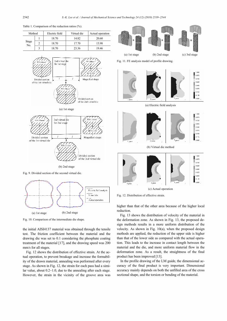
Fig. 12 shows the distribution of effective strain. At the ac-tual operation, to prevent breakage and increase the formabil-ity of the drawn material, annealing was performed after every stage. As shown in Fig. 12, the strain for each pass had a simi-lar value, about 0.2~1.0, due to the annealing after each stage. However, the strain in the vicinity of the groove area was
higher than that of the other area because of the higher local reduction.
Fig. 13 shows the distribution of velocity of the material in the deformation zone. As shown in Fig. 13, the proposed de-sign methods results in a more uniform distribution of the velocity. As shown in Fig. 10(a), when the proposed design methods are applied, the reduction of the upper side is higher than that of the lower side as compared with the actual opera-tion. This leads to the increase in contact length between the material and the die, and more uniform material flow in the deformation zone. As a result, the straightness of the final product has been improved [13].
In the profile drawing of the LM guide, the dimensional ac-curacy of the final product is very important. Dimensional accuracy mainly depends on both the unfilled area of the cross sectional shape, and the torsion or bending of the material.
Table 1. Comparison of the reduction ratios (%).
Method Electric field Virtual die Actual operation1 18.70 14.82 20.60 2 18.70 17.70 15.98
Stage No.
3 18.70 23.36 19.46
(a) 1st stage
(b) 2nd stage
Fig. 9. Divided section of the second virtual die.
(a) 1st stage (b) 2nd stage
Fig. 10. Comparison of the intermediate die shape.
(a) 1st stage (b) 2nd stage (c) 3rd stage
Fig. 11. FE analysis model of profile drawing.
(a) Electric field analysis
(b) Virtual die method
(c) Actual operation Fig. 12. Distribution of effective strain.

S.-K. Lee et al. / Journal of Mechanical Science and Technology 24 (12) (2010) 2539~2544 2543
Fig. 14 shows the FE analysis result for the unfilled area of the final product after the three-stage drawing. The unfilled area was measured in order to evaluate the dimensional accu-racy of the final products.
Table 2 shows the unfilled area of the final products. It can be known that the dimensional accuracy is improved when the proposed design methods are applied.
4.2 Profile drawing experiment
A multistage profile drawing experiment was performed to verify the effectiveness of the proposed design methods. A cold drawing machine at the actual operation site was used for the experiment. The drawing machine, the final drawn prod-ucts, and the cross section of the final products are shown in Fig. 15.
After the experiment, the unfilled areas of the final products were measured using a 3-D surface profiler. The measured results are summarized in Table 3. From comparison of the unfilled area between Table 2 and Table 3, although there is some difference between FE analysis and the drawing ex-periment because of the limited number and size of elements in the FE analysis, the results indicate almost the same ten-dency. This means that the dimensional accuracy of the final product can be improved when the proposed design methods are applied.
5. Conclusions
In this study, the electric field analysis method and the vir-tual die method are proposed to design the intermediate die shapes of the multistage profile drawing process. By using the proposed methods the intermediate die shapes are designed for producing a LM guide fabricated using a three-stage profile drawing in the actual operation site.
From the FE analysis result the unfilled area of the final product was measured to evaluate the dimensional accuracy of the final product. When the electric field and the virtual die method were applied, the unfilled area decreased by about
Table 2. Comparison of the unfilled area (FE analysis).
Design method Electric field Virtual die Actual operationUnfilled
Area (mm2) 1.507 3.171 6.761
(a) Electric field analysis
(b) Virtual die method
(c) Actual operation Fig. 13. Distribution of velocity in the deformation zone.
Fig. 14. The unfilled area of the final product.
Table 3. Comparison of the unfilled area (experiment).
Design method Electric field Virtual die Actual operationUnfilled
Area (mm2) 0.250 0.488 0.826
(a) Cold drawing machine
LM guide Electric field Virtual die Actual operation
(b) Final product Fig. 15. Profile drawing experiment.

2544 S.-K. Lee et al. / Journal of Mechanical Science and Technology 24 (12) (2010) 2539~2544
78% and 53% compared with that of the actual operation, respectively.
Finally, the result of FE analysis was verified through a pro-file drawing experiment performed using the actual drawing machine. Based on the experiment, when the electric field analysis and the virtual die method were applied, the unfilled areas decreased about 70% and 41%, respectively. The differ-ence between FE analysis and the drawing experiment is due to the limited number and size of elements in the FE model. However, the results indicate almost the same tendency.
The design of the intermediate die shape is one of the most important tasks in multistage profile drawing. Previously, this design has been done in an intuitive way based upon the ex-perience of industrial experts, which is expensive and time-consuming. The greatest advantages of the proposed design method is that it is possible to design the intermediate die shape of the profile drawing without excessive labor, reduce costs, and save time regardless of the geometric complexity. Therefore, the proposed methods can help die designers with-out sufficient practical experience, and can be applied to pro-file drawing for fabricating various profiles.
Acknowledgment
This research was financially supported by the Ministry of Education, Science, and Technology (MEST) and the Korea Industrial for Advancement of Technology (KIAT) through the Human Resource Training Project for Regional Innovation, and by Parts and Materials Technology Development Program funded by the Korean MKE.
References
[1] K. Yoshida and S. Tuihij, Multiple drawing of rails for linear motion guide, Advanced Technology of Plasticity, 1 (2002) 367-372.
[2] S. K. Lee, J. E. Lee, B. M. Kim and S. M. Kim, Die design in the complex shape drawing of cross roller guide, Journal of Mechanical Science and Technology, 21 (2007) 1573-1579.
[3] W. Steuff and R. Kopp, Estimation of designing methods for drawing of section rods and wire, Wire Journal International, 28 (1995) 104-109.
[4] H. C. Kim, Y. Choi and B. M. Kim, Three-dimensional rigid-plastic finite element analysis of non-steady-state shaped drawing process, International Journal of Machine Tools & Manufacture, 39 (1999) 1135-1155.
[5] S. K. Sahoo and P. K. Kar, Round-to-hexagon drawing through straightly converging dies: An application of the SERR technique, International Journal of Mechanical Sci-ences, 42 (2000) 445-449.
[6] K. K. Wang and V. Argyropoulos, Design and analysis of direct cold drawing of section rods through a single die, Journal of Materials Processing Technology, 166 (2005) 345-358.
[7] M. Brücker, D. Keller and J. Reissner, Computer-aided drawing of profiles from round and square bar, Annals of the CIRP, 37 (1998) 247-250.
[8] Y. C. Kim, D. J. Kim and B. M. Kim, Intermediate die de-sign system for the multi-stage drawing process, Trans. NAMRI/SME, 28 (2000) 69-74.
[9] M. Kobayashi, The present situation of cold drawn special section (in Japanese), Journal of JSTP, 39 (1998) 333-335.
[10] K. Yoshida, Production technology of shaped wire and bar for linear motion guide (in Japanese), Iron and Steel Institute of Japan, Bar and Wire Forum, 1999.
[11] M. S. Joun and S. M. Hwang, Pass schedule optimal design in multi-pass extrusion and drawing by finite element method, International Journal of Machine Tools & Manu-facture, 33 (1993) 713-724.
[12] J. P. Renz and R. Kopp, A new calibration method for complex shape sections with reflex angles, Wire Journal In-ternational, November (1998) 96-100.
[13] Y. C. Kim, D. J. Kim and B. M. Kim, A study on the corner filling in the drawing of quadrangle rod from round bar, Journal of Korean Society of Precision Engineering, 17 (6) (2000) 143-152.
[14] S. R. Lee, Y. K. Lee, C. H. Park and D. Y. Yang, A new method of preform design in hot forging by using electric field theory, International Journal of Mechanical Science, 44 (4) (2002) 773-792.
[15] The japan society for technology of plasticity, Drawing process (in Japanese), Korona, Japan (1990).
[16] K. Sawamiphakdi, G. D. Lahoti and J. Gunasekera, Devel-opment of utility programs for a cold drawing process, Jour-nal of Materials Processing Technology, 80-81 (1998) 392-387.
[17] Y. D. Park, S. H. Yoon, A study on friction and wear of manganese phosphate thin film, Annual Fall Conference of Korean Society for Precision Engineering (2004) 1384-1389.
Sang-Kon Lee received his Ph.D. de-gree from Pusan National University in Korea. He is a research professor in PNU-IFAM Joint Research Center at Pusan National University. His research interests include wire drawing, alumi-num extrusion and hybrid joining proc-ess.
Byung-Min Kim received his Ph.D. degree from Pusan National University in Korea. He is a professor in the school of mechanical engineering and the direc-tor of PNU-IFAM JRC at Pusan Na-tional University, Korea. His main re-search field is production and manufac-turing based on metal forming. Espe-
cially, He conducts research into wire drawing, aluminum extrusion, sheet metal forming and hybrid joining process.