
RESEARCH MEMORANDUM - NASA MEMORANDUM EXPERIMENTAL INVESTIGATION OF A 0.4 HUB-TIP DLAMETER RATIO....
37
RESEARCH MEMORANDUM EXPERIMENTAL INVESTIGATION OF A 0.4 HUB-TIP DLAMETER RATIO. AXIAL-FLOW .COMPRESSOR.. INLET. STAGE AT ).(ATiONAL i 3 ADVISORY COMMITTEE il ._ -e ar' FOR AERONAUTICS WASHINGTON _- https://ntrs.nasa.gov/search.jsp?R=19930089083 2018-06-02T13:03:31+00:00Z
Transcript of RESEARCH MEMORANDUM - NASA MEMORANDUM EXPERIMENTAL INVESTIGATION OF A 0.4 HUB-TIP DLAMETER RATIO....

RESEARCH MEMORANDUM EXPERIMENTAL INVESTIGATION OF A 0.4 HUB-TIP DLAMETER
RATIO. AXIAL-FLOW .COMPRESSOR.. INLET. STAGE AT
).(ATiONAL i 3 ADVISORY COMMITTEE i l ._
-e ar' FOR AERONAUTICS WASHINGTON _-
https://ntrs.nasa.gov/search.jsp?R=19930089083 2018-06-02T13:03:31+00:00Z
NACA RM E55L09
c
F,
EXPERIMEXTAL -TIGATION OF A 0 4 HUB-TIP D U " F z R RATIO AXIAL-F'LOW
111 - EFFECT OF TIP TAPER ON OVER-ALG AND BLADE-EL;GMENT PERFaRMANCES
By John C. Montgmery and Frederick Glaser
An investigation was.cmducted to determine the feasibility of in- creasing the tip-section blade-element efficiency of a transonic rotor by reducing the blade loading for a given design inlet relative Mach number. The 0.4 hub-tip diameter ratio transonic rotor was modified by tapering the outer casing inward across the rotor-blade row. The blades were unchanged except that the tips were machined down to fit the new outer-casing contour. The reduced outlet area and the streamline curva- ture thus obtained increased the outlet tip ax€d velocity and decreased the tip-section blade loading for a given inlet relative Mach number.
At the design corrected tip speed of '1000 feet per second,. the rotor modification increased the over-all-performance peak efficiency from 0.93 to 0.95 and decreased the maxFmum pressure ratio from 1.42 to 1.40. A larger useful weight-flow range was obtained for the modified rotor at design speed. A t 115 percent design speed, the over-all- performance peak efficiency for the rotor modification was 0.92.
At design speed, the rotor modification increased the tip-section blade-element peak efficiency from 0.80 to 0.92. The rotor modification also decreased the diffusion factor at the near-minimum-loss incidence angle of 4.5O at the tip section frm 0.45 to 0.30. For a even diffusion-factor value of 0.40, the rotor modificatim decreased the total-pressure-loss coefficient at the ro to r t i p section from 0.14 to 0.075.
Curvature on the outer casing had a pronounced effect on the rotor inlet and outlet axial-velocity distributions, and this effect should be included in obtaining velocity diagrams for designs which incorporate tip c-mature .
Cr
2 NACA RM E55U9 *
II
The investigation of the mer-a l l perf'onaance of a 0.4 hub-tip diameter ratio transonic rotor designed t o handle 34.9 pounds of air per second per square foot of rotor f rontal area (ref. I) has indicated that a rotor average efficiency of approximately 0.90 could be obtained with high flow capacity. A more detailed -lysis of the performance of each blade element of this rotor (ref. 2) indicated that the effi- ciency of the rotor-blade t i p section decreased markedly as the speed was increased t o the design speed. It i s pointed out in reference 2 that t h i s drop i n t i p efficiency with increase i n speed w m probably the resul t & the *reased blade loading (as defined by the diffusion .factor of ref. 3 and the axial-velocity reduction across the t i p sec- t ion) rather than the resul t of shock losses caused by the increase in the Elach nmber relative t o the rotor blade. Decreased tip-section blade-element efficiencies at design speed were also experienced f o r the transonic rotors of references 4 t o 6.
"
It was f e l t that a separation of the effects of blade loading and Mach number would be desirable i n order t o give a more conclusive ex- planation far the decrease i n tfp efficiency with increase in rotor speed. A simple technique for separation of these effects was, there- fore, derived. The original rotor was modified by inserting a spacer *
and tapering the outer casing-inward acr068 the rotor-blade row s o as t o reduce the area of the rotor out le t . The r o t o r blades were un- changed except that the tips were machined down t o f i t . ~ e altered outer- casing contour. The taper across +e rotor w a s made nonlinear so that the outer casing had a convex curvature. -Since &e outier casing was- not altered- upbtream o f the rotor-blade le- edge, the inlet geometry of the cmpressor wss unchanged.
.I
-
"
The effect of the reduced. area at the rotor outlet and the stream- line curvature introduced by the curvature (nonlinear taper) of the outer casing was to increase the axial velocity leaving the rotor fo r any given i n l e t Mach number. The effect. of the increase in axial veloc- i t y w a s , in turn, to decrease the diffusion factor at the ro tor t ip section for a given relat ive inlet Mach number.
The t i p section of the modified rotor wps taken, as in the case of the original rotor, as that section 10 percent of the passage height from the outer wall. Therefore, the geometry of the modified rotor- blade t i p section i s not identical to t he geometry of the t ip sect ion of the original rotor.
The difference i n blade geometry (camber, thickness, and chord) between the two rotor-blade t i p sections is sldght, and the effect of these .changes is considered snrall as cmpared with the change i n bdde loading. . .
Q 3 ..
3
NACA RM E55M9 3
W
m w CD cn
The present report discusses the over-all and blade-element per- formances of the modified rotor and ccanpares them with the performance of the original rotor. A discussion of the effects of-the streamline curvature introduced by the nonlinear taper of the outer casing on the velocity distributions through the &T111u1ar flow area i s a l so preseated.
APPARATlTS AND P R O C E D ~
Rotor Design and Modification
The rotor design i s presented i n de ta i l In reference 1. The rotor was designed t o produce a total-pressure r a t i o of 1.35 a t a specific corrected w e i g h t flow of 34.9 pounds per second per square foot of f rontal area and a t i p speed of 1000 feet per second. The diameter of the ro to r was 14 inches, and the inlet hub-tip dianeter r a t io w a s 0.4. The rotor was desiwed f o r axtal aAr inlet and constant energy addition along the radius.
For the modified-rotor, the outer-casing contour was altered by means of an imer t loca ted d o n g the outer casing, as sham in figure 1. The t ip i n se r t had a circular-arc taper of 4.5-inch radius, with the insert thickness increasing from zero at the rotor le-g edge t o a maximwn value of 0.25 inch a t the rotor outlet. With the effect of the streamline curvature due to the new outer-casing contour on the radial d3stribution of velocity neglected, the thickness of the insert w a s selected as that value required t o increase the axial-velocity ratio across the rotor at desi- speed approximately 10 percent (frm 0.92 for the untapered rotor t i p section to 1.02 for the tapered rotor t i p section). Because of the positive radius of curvature of the insert, the effect of streamline curvature would be an increase i n the axial- velocity r a t i o v,, 2/~z,1 across the r o t o r t i p to a vdue somewhat greater than the predicted IO-percent increase based on area change alone. The small radius of 4.5 inches w a s seiected rather arbitrarily so as t o accentuate the effects of streamline curvature in giving a large increase i n axial-velocity r a t i o f o r this investigation.
The modified rotor w a s tested with the altered hub contour shown i n figure 1. This al terat ion of the hub section had been made previously ul th the o r i g i n a l rotor for the purpose of reducing the loss through the hub section of the stator blades. As reported i n reference 2, the al- tered outlet hub section had a negligible effect on the stator-blade- element performance.
The t i p section of both the or ig ina l and m o d i f i e d ro tors was taken as that blade section 10 percent of the passage height frm the outer wall. Therefore, the designated blade t i p sections f o r the two ro tors varied, as shown i n figure 1. The contour of the two rotor-blade t ip
4 NACA RM E55L09
.
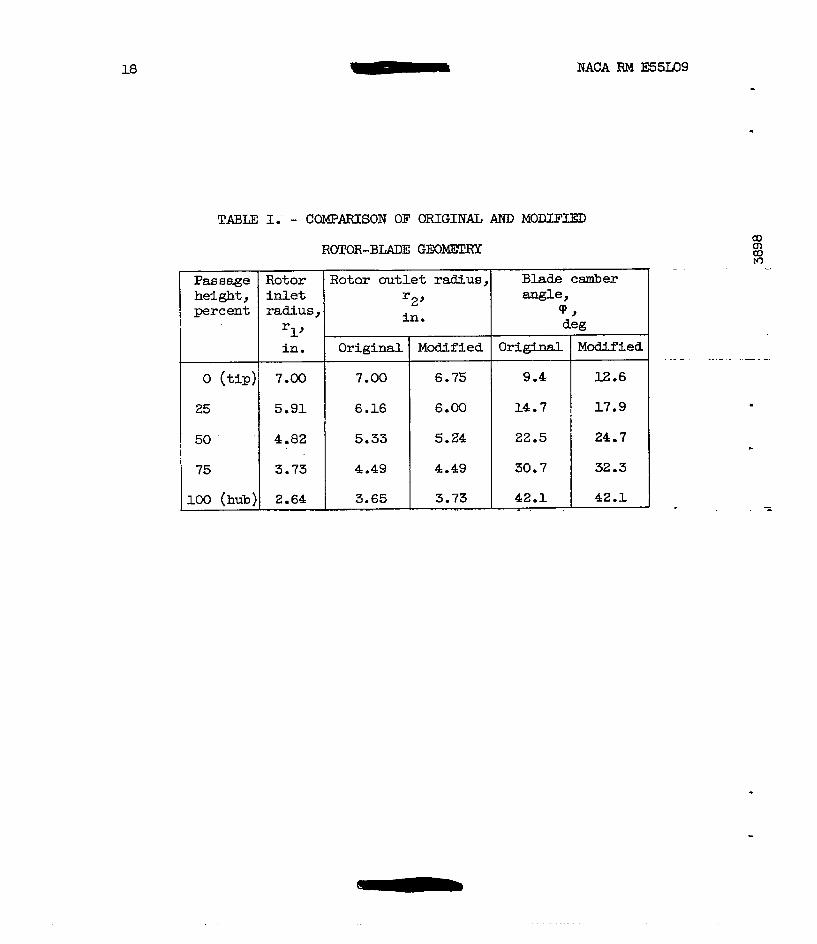
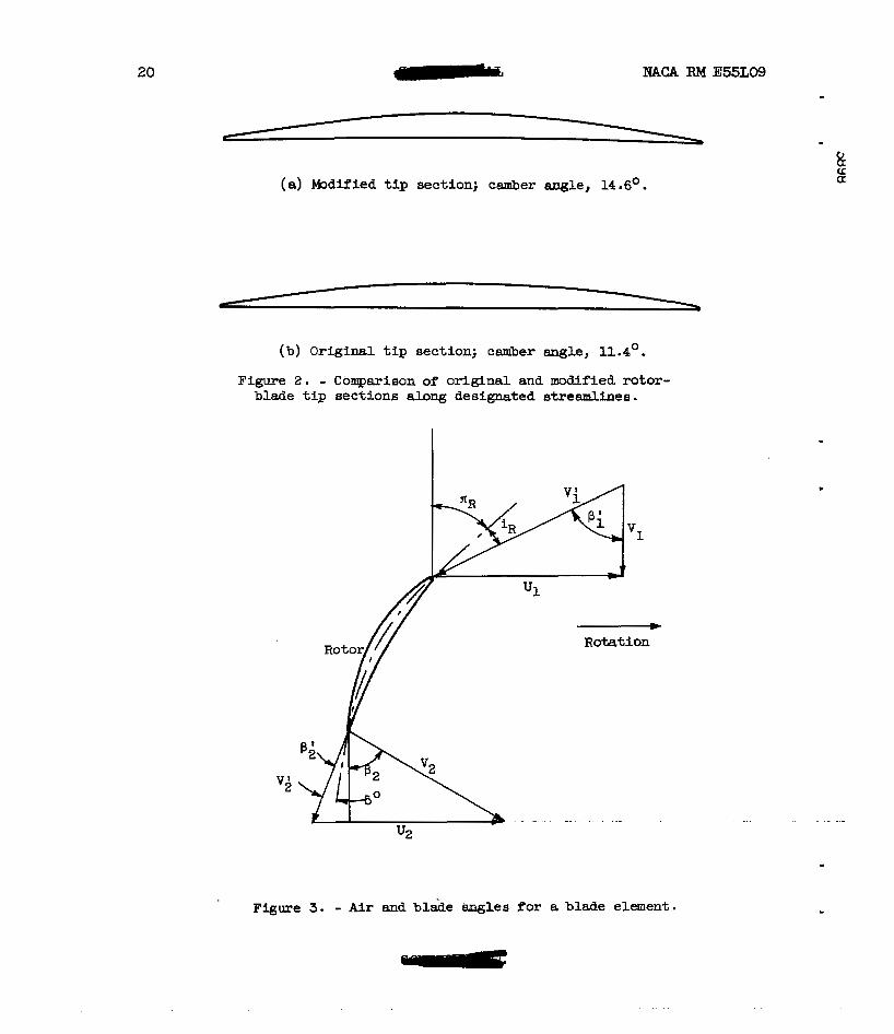
sections i s shown in f igure 2. The variation i n chord length between the two blade sections i s negligible, but the blade camber angle was I increased from ll.4O f o r the untapered r o t o r t o 14.6' for the modified or tapered rotor. The blade tip-section contours shown in f igure 2 are copies of prints made 20 times the actual s ize of the blade contour taken along the two t i p sections, as sham i n figure 1. The variation of the blade camber angles and the outlet-measuring-station radius r a t i o s f o r the original and modified rotors are presented i n table I.
In order t o minimize or eliminate the effect of variatlans of t i p clearance in this investigation, the t i p clearance was maintained a t the same value (0.025 to 0.028 in. 1 used f o r the original rotor investigation.
W '
Compressor Installation and Instrumentation
The compressor ins ta l la t ion and instrumentation are the same as , those described in reference 2 except that (1)'messurements after the
rotor were recorded continually by an automatic recorder as each in- 5
strument was traversed radially across the rotor passage height, and ( 2 ) t he i ac i l i t i e s of the test unit w e r e a l tered during the t e s t pro- gram so that refrigerated air (down t o -60° F) could be supplied to the - compressor in le t .
The f a c i l i t i e s f o r supplying refrigerated a i r t o the canpressor inlet were not installed u n t i l after the modified rotor was tested a t corrected t i p speeds of 600, 800, 1000, &id 1050 feet per second. The instal la t ion of the refrigerated air system enabled the overspeed run of 115 pepcent of design speed (or EL t i p speed of 1150 ft/sec) to be made without increasFng the actual mechanical speed of the rotor above the value previously used a t 105 percent design speed.
The weight flow indicated by the new orif ice used f o r the runs at 115 percent design speed was approximately 2-percent less than the weight flow indicated by the original M e t orifice. Therefore, i n order to present a consistent aver-all cmsressor performance nag, the weight flows measured by the new or i f ice (ll5-percent-design-speed runs) were corrected to that value which would have been measured by the original orifice.
A plug-type vibration p i c h p mounted in the casing over the rotor was used to indicate blade vibratians. The plug-type vibration pickup i s a magnetkc-type unit. which generates a voltage proportional to the velocity of the rotating blade. The plug-tgpe pickup is used i n con- junction with an oscilloscope to produce 8 continuous pattern which i e proportional t o the blade speed. When blade vibratian occurs, the voltage output of the pickup plug i s increased for the fked rotat ional speed, and this increased voltage (increased blade velocity) i s indi- cated on the oscilloscope pattern. I
. b

NACA RM E55LO9 n
5
Procedure . Data f o r the modified rotor were taken a t corrected speeds of 60,
80, 100, 105, and 115 percent of design speed. A t each speed the weight flow was varied over the ccanplete vibration-free weight-flow range. The over-all performance of the rotor i s presented as arith.net,- i ca l ly averaged values so as t o be consistent with the data presented in references 1 and 2.
b 4 m W Q,
The symbols and equations used in computing the blade-element and over-all performance are included i n appendixes A and B, respectively. A typical velocity diagram i l lus t ra t ing the air and blade angles is given In figure 3,
COMPAEUSON O F ORIGINAL AND MODIFIED RoTaR -CES
Over-All Performance
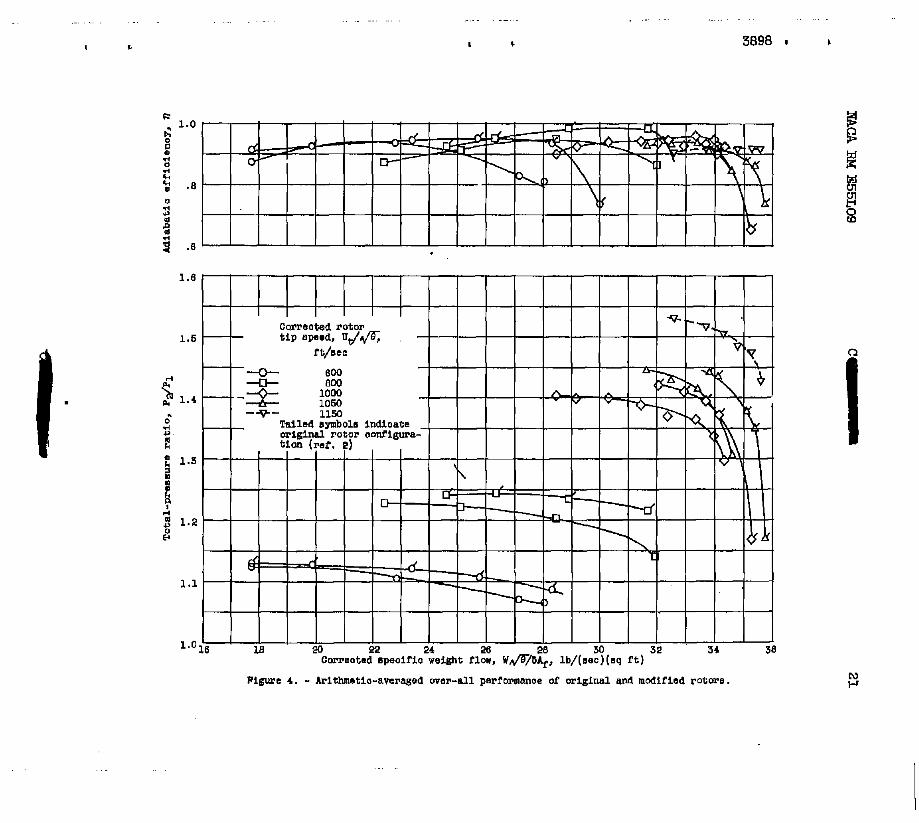
P The over-all performance of the modified rotor i s canpared with
Y A t a corrected t ip speed of US0 feet per second, data are presented
the over-all performance of the o r i g i n a l rotor (ref. 2) in figure 4 f o r corrected t i p speeds of 600, 800, 1000, 1050, and ll50 fee t per second.
only f o r the modified rotor because refrigerated air w a s not available for the tests of the o r i g i n a l rotor configuration. The overspeed data of U50 feet per second tire presented 86 dashed curves i n order to in- dicate that the w e i g h t flow was corrected to the value which would have been indicated by the- original inlet measuring or i f ice .
For the modified rotor, the design-speed total-pressure ratio of 1.35 (the design value f o r the o r i g i n a l ro tor ) w a s obtained at a cor- rected specific w e i g h t flow of 33.7 pounds per second per square foot of f rontal area and at an adiabatic efficiency of 0.95. The peak effi- ciency a t design speed was also 0.95. Peak efficiencies of 0.94, 0.95,
spectively. For the refrigerated overspeed run of l l50 feet per second, a peak efficiency of 0.92 was obtained.
and 0.94 were O b t a F n e d &t 60, 80 and 105 perCMt design Speed, re-
The effect af the rotor modification (fig. 4) was t o decrease the specific w e i g h t flow f ram 34.4 t o 33.7 pounds per second per square foot of f rontal azea at design speed and a total-pressure ratio of
. 1.35. A t this same pressure mtio, the adiabatic efficiency w a s in- creased from 0.87 t o 0.95. The peak efficiency a t design speed. w a s increased from 0.93 to 0.95 as a result of the rotor m o d i f i c a t i o n . The peak pressure ratio was decreased a t all speeds as a result of the
peak pressure ratio decreased from 1.42 to 1.40. L increase in out le t axial velocity. For instance, at design speed, the
6 NACA RM E 5 5 m .
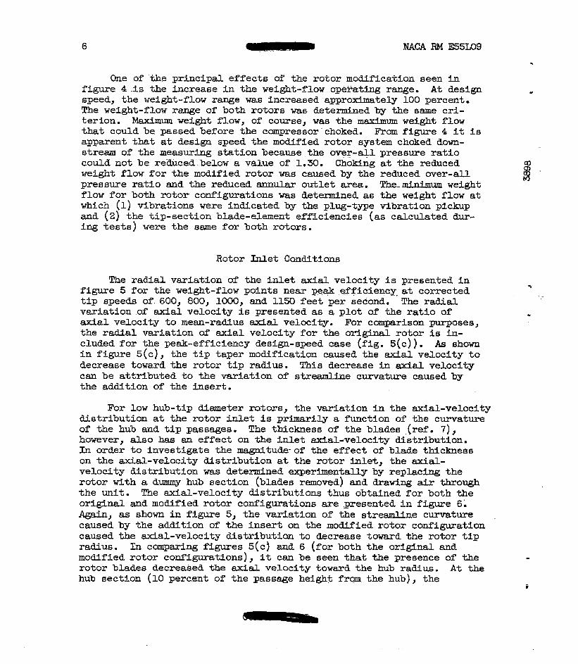
One of the principal effects of the rotor modification seen in figure 4 3 s the Fncrease in the weight-flow operating rage. At design speed, the weight-flow range w a ~ ~ increased approldmately LOO percent. The weight-flow range of both rotors -6 determined by the same cri- terion. -Maximum weight flow, of cowse, was the maximum weight flow that could be passed before the campressor-choked. From figure 4 it is apparent that at design speed the modified rotor system choked down- stream of the measuring station because me over-all pressure ratio could not be reduced-below a value of 1-30. Choking at the reduced weight flow for the modified rotor was caused by the reduced mer-all pressure ratio and the reduced annul&r outlet area. The-ruinimm weight flow for both rotor configur&tions was determined as the weight flow st which (1) vibrations were indicated by the plug-tne vibration pickup and (2) the tip-section blade-element efficiencies (as calculated dur- ing tests) were the same for both rotors.
Rotor Inlet Conditions
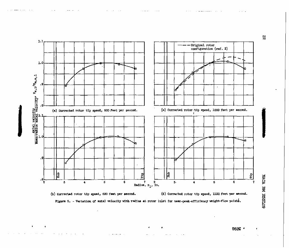
The radial variation of the inlet axial. velocity is presented in figure 5 for the weight-flow points near peEllr..efficiency-at corrected tiy speeds of 600, 800, 1000, and 1150 feet per second. The radial vexiation of axial velocity is presented as a plot of the ratio of axial velocity to mean-radius Ewdd velocity. For ccanparison purposes, the radial variation of axial velocity for the or igLnal rotor is in- cluded for the peak-efficiency design-speed case (fig. 5(c)). As sham i n figure 5 ( c> , the tip taper modification caused the axial velocity to decrease toward the ro to r tip radius. This decrease in axial velocity can be attributed to the variation of streamline curvature caused by the addition of the insert.
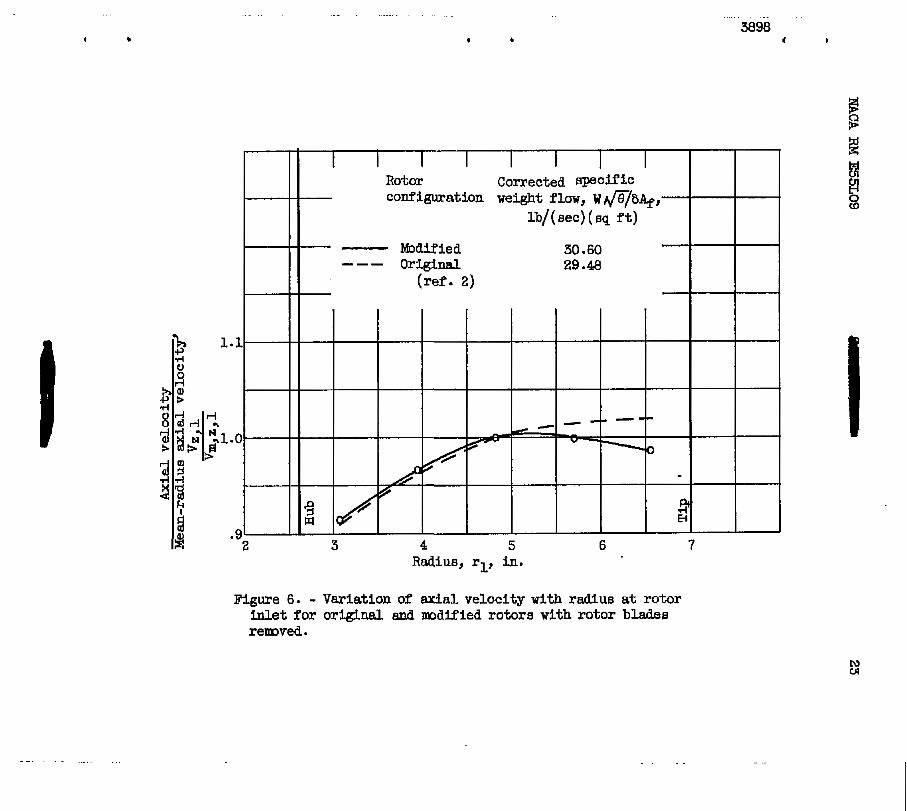
For low hub-tip diameter rotors, the variation in the axial-velocity distribution at the rotor Inlet is primarily a functlon of the curvature of the hub and tip passages. The thickness of the blades .(ref . 7), however, also has an effect on the inlet axial-velocity distribution. In order to investigate the -tude- of the effect of blade thickness on the axial-velocity distribution at the rotor inlet, the axial- velocity distribution was determined experimeptally by replacing the rotor with a dummy hub section (blades removed) and drawing air through the unit. The-axial-velocity distributions thus obtained for both the original and modified rotor configurations are gresented in figure 6 . Again, as shown in figure 5, the variaticm of the streamline curvature caused by the addition of the insert on the modified rotor configuration caused the &al-velocity distrfbutian to decrease toward the rotor tip radius. In comparing figures 5(c) and 6 (for both the original and modified rotor configurations), it can be seen that the presence of the rotor blades decreased the ax ia l velocity toward the hub radius. At the hub section (10 percent of the passage height frqmthe hub), the

NACA RM E55LO9 7
presence of the blades deckeased the axial velocity apprclx-ltely 4 per-
resul t of blades blocking more of the passage area at that section and forcing the flow up radially.
- cent. This decrease i n axial velocity toward the hub section is the
m CN
a, (D
The radial variation of the re la t ive in le t air angles f o r the m o d i - fied rotor are presented in figure 7 for the weight-flow points near peak efficiency a t corrected t i p speeds of 600, 800, 1000, and 1150 f ee t per second. The design relative inlet d r angles and the design blade inlet angles are included i n figure 71c) for the design-speed case. The difference between the desi& and actual re la t ive inlet air angles can be attr ibuted t o the deviation frm the design w e i g h t f l ow and the design axial-velocity distribution. As pointed out in refer- ence 2, the rotor was designed f o r a weight flow of 34.9 pounds per second per square foot of frontal area with constant inlet axial veloc- i t y assumed along the radius.
Rotor Outlet Conditions r As in the case for the rotor inlet , the axial-velocity distribution
a f t e r the ro to r was experimentally determined with the dmmy hub section
velocity distributions thus obtained are presented in figure 8 for both the original and modified rotor configurations. The effect of hub curva- ture i n the original rotor configuration (constant t i p diameter) i s an increase in the Etxfal velocity toward the hub radius. This i s the re- sult of the static-pressure gradient (high static pressure a t the , t ip, low at the hub) which i s imposed by the hub curvature. The addition of t i p curvature i n the m o d i f i e d rotor configuration reduces the effect of hub curvature and increases the mal velocity toward the t ip rad ius .
- (blgdes removed) and with air drawn through the rotor. The axial-
Although the results of figure 8 were obtained d t h the dunrmy hub section, the axial-velocity distributions thus obtained after the rotor are indicative of those f o r ideal free-vortex flow through a rotor. This is true since, f o r idea l vortex flow through a rotor (zero gradi- ents of stagnation temperature and entropy), the variation of axial velocity after the blade row i s determined entirely by the curvature of the inner and outer walls (effect of blade thickness neglected).
Since true vortex flow is not achieved through a rotor, it i s not surprising that the actual axial-velocity distributions after the rotor (fig. 9) do not coincide with the axial-velocity distributions f o r the free-vortex c a ~ e (blades removed) (fig. 8). Figure 9 is a plot of the axial-velocity distribution after the rotor for the original and modi- fied rotors at a flow near the peak-efficiency point a t design speed. The velocity distribution after the modified rotor (f ig. 9) appears t o be very similar t o the velocity distribution measured i n the flow test
8 NACA RM E55Lo9
of the modified anrtular passage ( f i g b 8 ) . The axial-velocity distribu- tion of the original rotor (fig. 91, however, varies samewhat from the velocity passage. gradient
near the th8,t was
(fig.. 9)
distribution measured-in -&e f low tests of the original annular
of axial velocity is much greater xith the blad.ee installed than with the blades removed (fig. a). The low axial velocity tip is the result of the large loss (large entropy gradient) indicated near the tip of the o r i g i n a l rotor (ref. 2).
- It is apparent that, for the o r i g i n a l configuration, the radial
Blade-Element Perforname At Design Speed
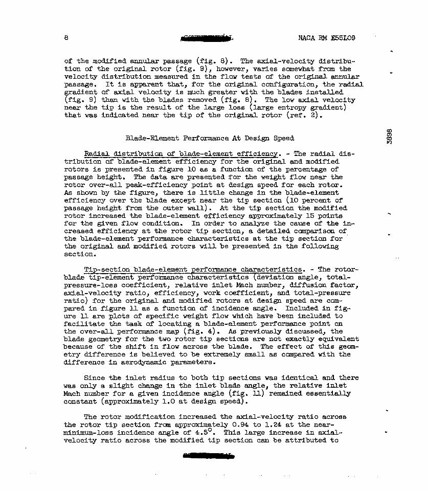
Radial distribution of blade-element efficienq. - The radial dis- tribution of blade-element efficiency for the orlgii and modified rotors is presented in figure 10 as i functian oYthe percentage of passage height. The data are presenked for the weight flow near the rotor over-all peak-efficiency point at design speed for each rotor. As shown by the figure, there is Httle change in the blade-element efficiency over the blade except near the tip section (10 percent of passage height from the outer wall). At the tip section the modified rotor incre~sed the blade-element efficiency appmximately 15 points for the given f law conditim. I n order to agalyze the cause of the in- creased efficiency at the rotor tip sectfon, a detailed cmpax!.son of - the blade-element performance characteristics at the tip section f o r the original and modified rotors will be presented in the following section.
-
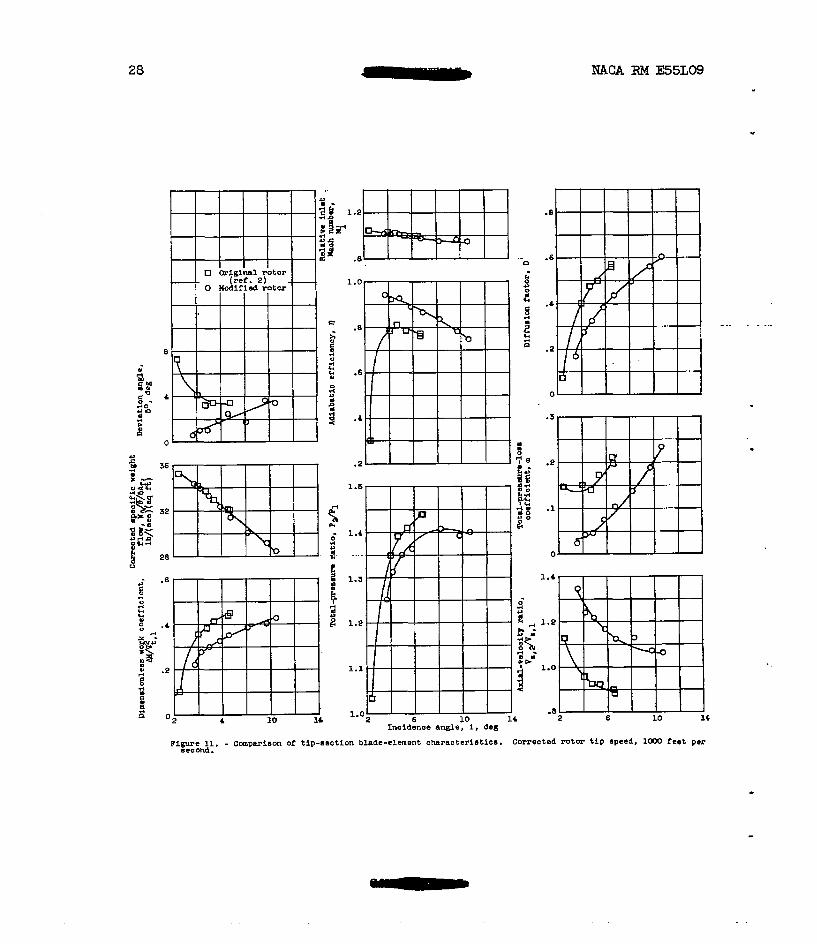
Tip-section blade-element performance characteristics. - The rotor- blade tip-element performance characteristics (deviation angle, t o t a l - pressure-loss coefficient, relative inlet Mach nmber, Ufusion factor, axial-velocity ratio, efficiency, work coefficient, and total-pressure ratio) for the original and modified rotors at design speed are cam- pared in figure ll a6 a function of' incidence angle. Included in Pig- w e ll are plots of specific weight flow which have been included to facilitate the task of locating a blade-element performance point on the over-all performance map (Fig. 4) . As prevfously dfscussed, the blade geometry for the two rotor tip sections are not exactly equivalent because of the shift in flow across the blade. The effect of this gem- etry difference is believed to he extremely small as canpared Kith the afference in aerodynamic parameters.
Since the inlet radius to both tip sections waa identical and there was on ly a slight change in the inlet blade angle, the relative Inlet Mach number f o r a given incidence angle (fi . I L L > remained essentially constant (approximately 1.0 at design speed f .
The rotor modification increased the axlal-velocity ratio acros8 the rotor tip section frm approximately 0.94 to 1.24 at the near- anirnum-loss Lncidence angle of 4.5'. hie large increase in velocity ratio across the modified tip section can be attributed to
c
Y

NACA RM E55L09 -
(1) the increase in blade-element efficiency (the reduced entropy - gradient) and (2) the thickness end curvature of the insert.
9
N D D D
At an incidence angle of 4.5' (approximate minimum-loss incidence angle), the rotor modification decreased the diffusion factor at the tip section frcm 0.45 ta 0.30. The total-pressure-loss coefficient was decreased f r o m 0.14 to 0.04, and the corresponw adiabatic efficiency increased f r m 0.80 to 0.92. For a given diffusion-factor value near the minimum-loss incidence angle, the rotor modification reduced the total-pressure-loss coefficient even though the incidence angle w&s increased. For e w l e , at a diffusion factor of 0.4, the rotor modi- fication decreased the total-pressure-loss coefficient f r m 0.14 to 0.075 even though the incidence angle was increased fran 40 to 6O. It is interesting to note that maximum incidence angle (fig. U), as deter-
occurred approximately at the same value of diffusion factor for the original and modified rotors. It should be pointed out,' however, that the ndnimum incidence angle for the m o d i F l e d rotor was determined by the flow lfmitations of the rig. As pointed out previously i n the section
- Over-All Performance, the modified rotor configuration choked downstream of the measuring station, and it was not possible to obtain the absolute minlmum value of Fncidence angle.
I mined by the vibration pickup plug and the ti2 blade-element efficiency, >
- Although the camber angle of the modified tip section was greater
than that of the original rotor, the total-pressure ratio and the di- mensionless work coefficients at an incidence angle of 4.5O decreased f m 1.38 to 1.33 and frm 0.38 to 0.29, respectively. The increased turning at the tip section for the modified rotor tended t o increase the blade-outlet tangential velocity and therefore the work input and total-pressure ratio; however, the increased axial-velocity ratio over- ccrmpensated this effect and actually decreased the work input and total- pressure ratio across the blade section.
The decrease Fn deviation angle at optimum incidence angle is as- sumed to be caused by either the increase in axial-velocity ratio or the decrease in the total-pressure-loss coefficient. In accordance w5th C a r t e r ' s rule (ref. 8), the deviatim angle f o r the modified tip section should have been approximately 0.So greater tha~ the deviation angle for the original tip section because of the slight camber difference,
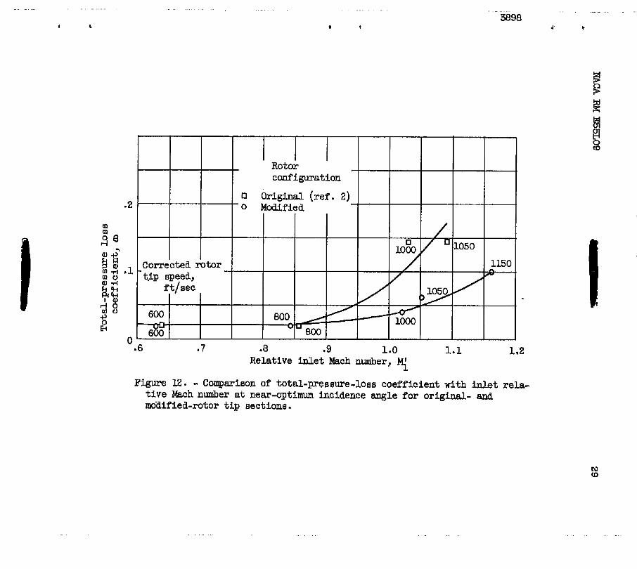
The variation of the rotor-blade tip-section total-pressure-loss coefficient at the near-minimum-loss incidence angle with inlet rela- tive Mach nuniber is presented in figure 12 for the o r i @ d and moa- fied rotor at tip speeds of 600, 800, 1000, and 1050 feet per second and U.50 feet per second for the modLfied rotor. For higher values of
than that of the o r i g i n a l rotor. For example, at RII inlet mch number of 1.05 the rotor modification decreased the loss coefficient frm
- relative inlet Mach number, the modified-mtor l o s s coefficient is less
-

10 NACA FW E55IQ9 -
0.125'to 0.05. These results show that the decreased loss obtained with the rotor modification of the higher wheel speeds is a result of .. the blade loa- rather than the inlet relative Mach number.
Although the two-dimensional diffusion factor is used a8 a blade- l o a m parameter, it may not be a general blade-loading criterion in actual three-dimensional flow. The magaitude of the loss coefficient affects the velocity ratio across the rotor, w h i c h , in turn, influences the magnitude of the diffusion factor st the blade element. In addi- tion, the velocity ratio fnfluences the boundary-layer characteristics 00
along the ~ U U S walls, which may, in turn, influence the blade-element characteristics. In general, the three-dimeneional character of the flow makes the two-dimensional evaluated diffusion factor only an ap- proximate blade-loading parameter.
m Q) W-J
Outlet boundary-layer blockage factor. - The outlet boundary-layer blockage factor is defined as the r a t i o of the ideal to the actual weight flow along the radius at the rotar outlet measuring station. Actual weight flow is determined by integrating. a curve of weight flow against radius; ideal weight flow is determined by extrapolating the - general contour shape of the actual weight-flow curve through the boundary-layer regions to the walls and integrating the resultant curve. Curves of actual and ideal weight flows against radius are presented in L
figure 13 for both .*e original. and modLfied rotars for the near over- all peak-efficiency weight-flow points at design speed. The shaded areas of figure 13 represent the difference between the actual and ideal weight flows. The shaded area for ~ the modified rotor (fig. 13) is smaller than the shaded area for the original rotor and represents a decrease in the boundary-layer blockage factor from approximately 3 to 12 percent. 1
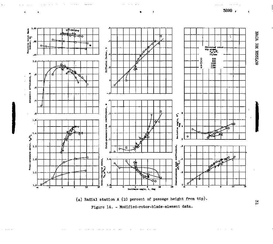
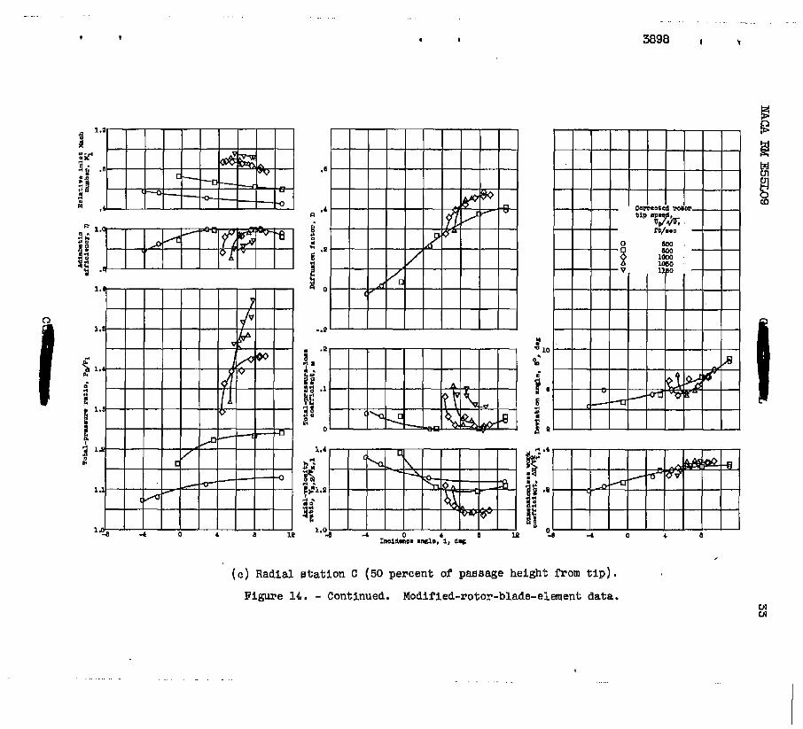
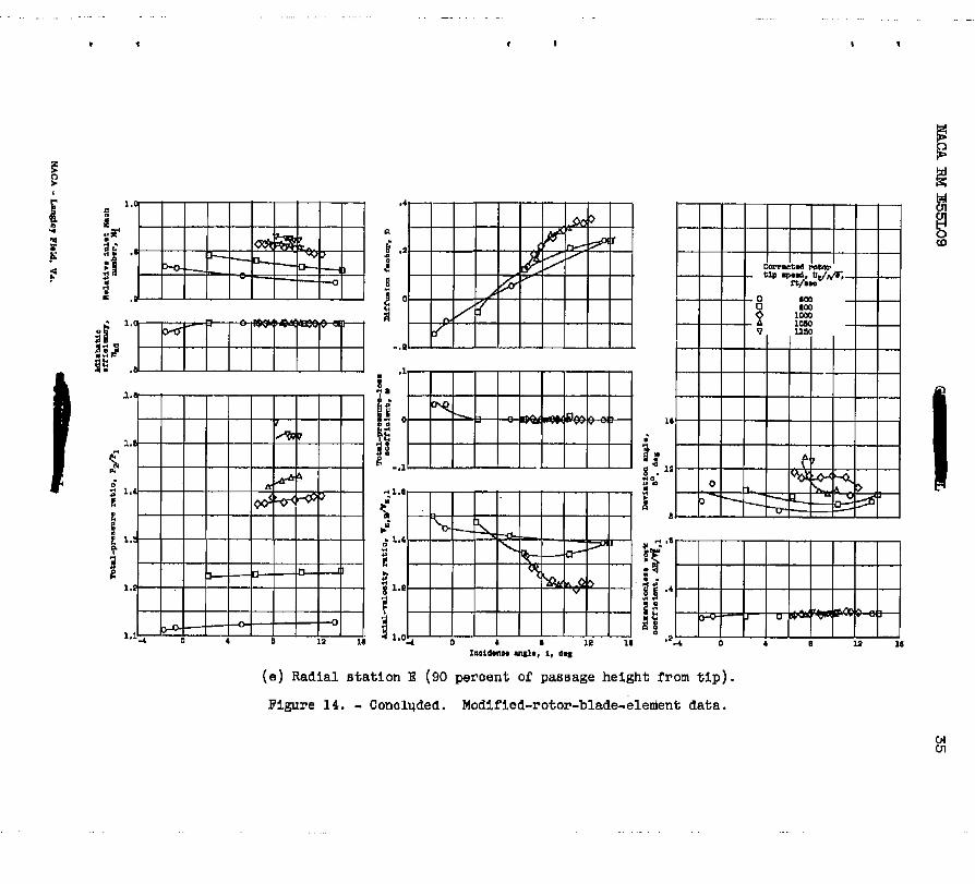
TPle blade-element performance characteristics of the modified rotor tip section at design speed are presented in figure 11 together with the blade-element performance characteristics of the original rotor tip eec- tion. In figure 14, the blade-element performance characteristics of the modified rotor are presented for aJ1 five of the W o r radial meas- uring stations (10, 30, 50, 70, and 90 peiicmt of the passage height from hub to tip) f o r the corrected tip speeds of 600, 800, 1000, 1050, and ll50 feet per second. The extensive data are presented to f'urther supplement the published data on transonic rotor-blade perfomce. In general, except for the rotor ti5 secti-aii,: the- trend of the various blade-element performance characteristics with incidence angle are c m - - sistent with the trends observed for the ori@;Inal rotor (ref. 2). Therefore, only an abbreviated discussion of the modified-blade-element performance will be included. - "

NACA RM E55L09 11
D Y 3 D
As previously exgerienced, the mhiram total-pressure-loss coeffi- - cient at the rotor t ip section (fig. 14(a) ) increased and shif ted to
higher values of incidence angle as the speed or re la t ive in le t Mach nuniber was increased. Althoughit would have been desirable t o deter- mine the loss - incidence angle relation of lower incidence angles f o r higher speeds, the tes t - r ig flow-area l h i t a t i o n s prevented operation in this region.
Some of the blade-element characteristics a t a corrected t ip speed of 1150 feet per second did not vary consistently with the corresponding blade-element characteristics at the lower t i p speeds and were canitted in figure 14. The deviation angle, for instance, increased sharply f o r all radial positions. The axial-velocity ratio across the rotor (near optbum incidence angle) increased rather than decreased as the t i p speed w a s increased frm 1050 t o U50 feet per second. Also, the dif- f’usion factor decreased pronwcedly as the t i p speed was increased from 1050 t o Il50 feet per second. A thorough examination of the data at a t i p speed of 1150 fee t per second indicated that an error w a s made i n measuring the absolute outlet angle after the ro tor . Th i s e r ro r i s at-
with the compressor Euds during the test run at ll50 feet per second.
d 3 a Q tr ibuted to the angle measuring instrument not being correctly alined
3 3 For example, an increase of approximately + i n the measured outlet lo
an@;leowould decrease the deviation angle approximately 2O at the t i p and 4 at the hub. A decrease i n deviation angle w o u l d decrease the axial-velocity ratio across the rotor and increase the diffusion f a c t o r . Calculation showed that an error of approximately 42 i n the measured out le t angle would make the data (deviation angle, axial-velocity ra t io , and diffusion factor) consistent with the data measured at the other speeds. A check of the integrated weight flows after the rotor also indicated better agreement when the absolute rotor outlet angle w a s in- creased. The remaining blade-element character is t ics ( re la t ive inlet Mach number, efficiency, total-pressure r a t i o total-pressure-loss co- efficient, and dimensionless work coefficientj w o u l d not change since they are measured independently and are not a function of the measured outlet angle. For this reason the Il5-percent data, which are a func- tion of the measured out le t angle, were mitt& In figure 14.
lo
SUMMARY OF €LESUZCS
The 0.4 hub-tip diameter ratio transonic rotor w a s nodified by in- troducing t i p curvature t o reduce the rotor tip-section blade loading. In cmgarison with the performance of the original rotor configuration,
” the following results were obtained:
1. A t d e s a corrected t i p speeds of lo00 feet per second, the - rotor modification increased the over-all peak efficiency from 0.93 t o

12 NACA RM E55L09
0.95 and decreased the maximum pressure ratio from1.42 to 1.40. The rotor modification also had a larger useful weight-flow range a t design speed. A t 115 percent design speed, the mer-all-performance peak effi- ciency for the rotor modification was 0.92.
2. T i p curvature across a rotor-blade row had a pronounced effect on-the axial-velocity distribution before and after the rotor and may be a useful design too l in cmtrolHng blade-element loading. For the given t i p contour, the axial velacity decreased toward t h e t i p a t the ro tor in le t and increased toward the tip at the rotor outlet . The ef- f e c t of these velocity changes was a marked reduction in tip loading.
3. A t design speed, the rotor modification hcreased the t ip- section blade-element peak efficiency iran 0.80 t o 0.92. The rotor modification a l so decreased the diffusion factor from 0.45 to 0.30 and increased the axial-velocity ratio frcm 0.94 to 1.24 a t the tip section for the near-minimum-loss incidence angle of 4.5O.
4. For a given diffusion-factor value of 0.40, the rotor modifica- tion decreased the total-pressure-loss coefficient a t the t i p section from 0.14 t o 0.075. This value of diffusion factor waB obtained i n the modifiedrotor at an -incidence angle appreciably greater than the minimum-loss value.
5. Comparison of the performance of the modified rotor w i t h the performance of the original rotor indicated that the decrease i n t i p efficiency with increase in speed that w a s noted in the tests of the original rotor was the result of the increased blade loading rather than the increased inlet re la t ive Mach number.
Lewis Flight Propulsion Laboratory National Advisory Cammittee f o r Aeronautics
Cleveland, Ohio, December 7, 1955

NACA RM E55LO9 c
13
D
g
H
A i
- J
M
mIS The foUowing symbols are used in this report:
A,B,C,DJEJ blade radial measuring stations
Af ccarrpressor f rontal area, sq f t
?e specific heat of air at constant pressure, Btu/(lb) (%I
n
P
r
T
r 6
I
diffusion factor
acceleration due to gravity, 32.17 ft/sec
t o t a l enthalpy, ft-lb/lb
angle of incidence, angle between w e n t t o blade mean
2
camber l i ne at leading edge and inlet-air direction, deg
mechanical equivalent of heat, 778 ft-lb/Btu
Mach nmber
summation value
t o t a l pressure, lb/sq ft
radius, in .
t o t a l temperature, OR
blade speed, ft/sec
velocity of dr, ft /sec
weight flow J lb/SeC
angle between velocity vector and rotor a x i s , deg
ra t io of specific heats
r a t io of inlet pressure to standard NACA sea-level pres- sure , P/2ll6.2
14 - NACA RM E55LO9
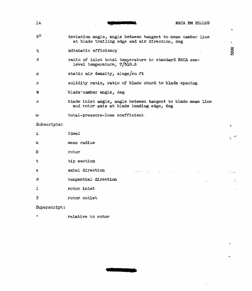
60 deviation angle, angle between tangent to mean camber l ine st blade trailing edge and air directicm, deg
tl adiabatic efficiency
e ratio of inlet total temperature to standard NACA sea- level temperatuie, T1518.6
P static air density, sluge/cu ft
d solidity ratio, ratio of blade chord to blade spacing
cp blade-camber angle, deg
It blade inlet angle, angle between tangent to blade mean lFne and rotor a x i s at blade leading eQe, deg
cu total-pressure-lose coefficient
Subscripts:
i ideal
mean radius
rotor
tip section
axial directton
e tangential. direction
1 rotor inlet
2 rotor outlet
Superscript:
I
f relative to rotor
NACA RM E551;09 15
EQIJA!I'IONS
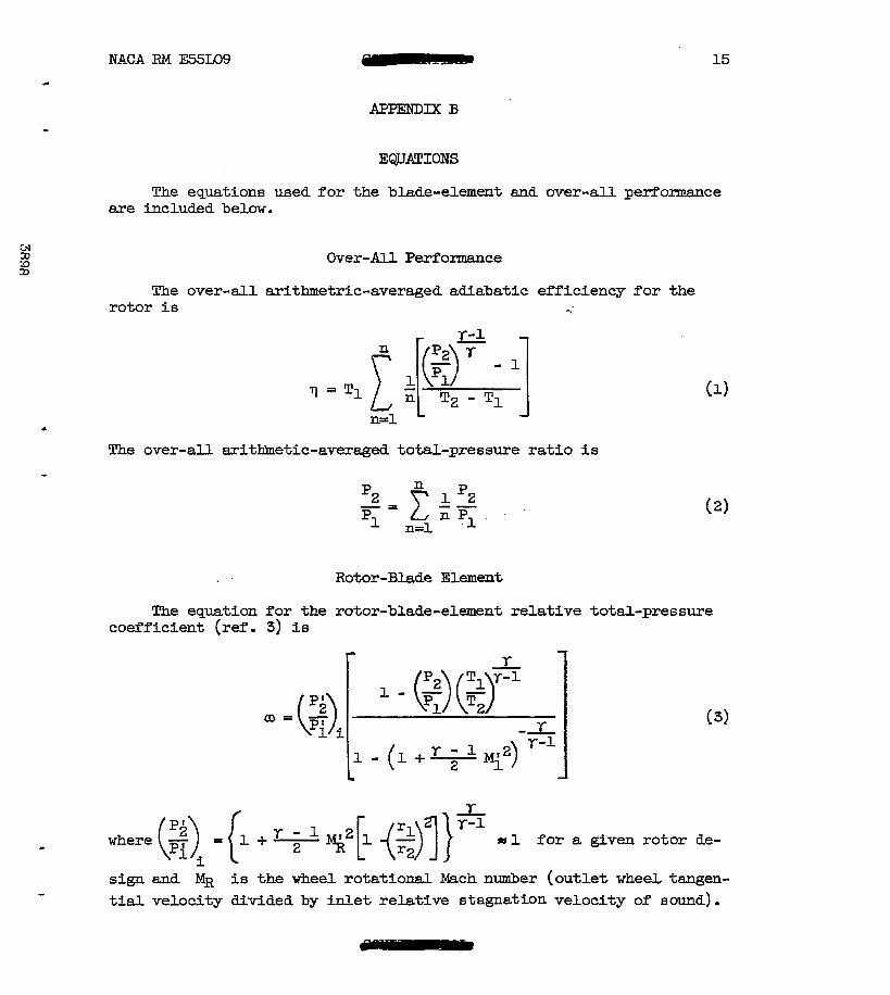
The equations used for the blade-element and over-all performance m e included below.
Over-All Performasce
The over-dl arithmetric-averaged adiabatic efficiency for the rotor is -,
The over-all aritlfmetic-averaged total-pressure ratio is
Rotor-Blade Element
The equation for the rotor-blade-element relative total-pressure coefficient (re. 3) is
LD=
I
- where (z)i = {l + % - q2 [l -($)I} '-' ss 1 for a given rotor de-
sign and MR is the wheel rotational Mach number (outlet wheeL tangen-
tial velocity divided by inlet relative stagnation velocity of sound).

16 NACA RM E55L09
The blade-element adiabatic efficiency is
In terms of U, Mi, and T2&, the blade-element adiabatic efficiency (ref. 4) is f o r (P;/P~)~ = 1.0
The following i s the equation f o r the dimensionless w o r k coeffi- cient (ref. 4) :
The diffusion factor (ref. 3) is
1; Serovy, George K., Robbas , William H., and Glaser, Frederick W.: Experimental Investigation of a 0.4 Hub-Tip Diameter Ratio Axial- Flow Compressor In le t Stage a t T r m a n i c Inlet Relative Mach N u - 'bers. I - Rotor Design and Over-All Performance a t Tip Speeds from 60 t o la0 Percent of Design. NACA RM E.53111, 1953.
2. Montgomery, John C., and Glaser, Frederick W.: Eqerimen-1 Investi- gation of a 0.4 Hub-Tip Diameter Ratio Axial-Flow Canpressor Inlet Stage at Transonic Inlet Relative Mach Numbers. II - Stage and Blade-Element Perforinance. NAW RM E54129, 1955.

NACA RM ES5LO9 1 17
3. Ueblein, Seymour, Schwenk, Francis C., and Broderick, Robert L.:
i n Axial-Flow-Canpressor Blade Elements. NACA RM E53DO1, 1953. - Diffusion Factor for Estimating Losses and Limiting Blade Loadings
4. Schwenk, Francis C., Ueblein, Seymour, and Lewis, George W., &.: Etxperimendl Investigation of an Axial-Flow Compressor W e t Stage Operating at Wansonic Relative In l e t Mach Embers. IU: - Blade- Row Performance of Stage with Transonic Rotor and Subsonic Stator
CEl at Corrected Tip Speeds af 800 and loo0 Feet Fer Second. NACA RM (0 E53G17 , 1953. tD (D
5. Robbins, William H., and Glaser, Frederick W.: Investigation of an Axial-Flow-Compressor Rotor with Circular-Arc Blades Operating up t o a Rotor-Met Relatfve Mach Number of 1.22. NACA RM E53D24, 1953.
6. &hWeIlk, Francis C., and kWi6, George W., Jr.: Ibrperimentsl In- vestigation of a Transonic Axial-Flow-Compressor Rotor with Double- Circular-Arc Airfoil Blade Sections. Iu: - Cmparison of Blade-
1955. A Element Peflormance . . . . . . . with . . - . Three - . - Levels of Solidity. " NACA RM E55FO1,
- I 7. S t a n i t z , John D.: Effect of Blade-Thickness %per on axial-Velocity Distribution a t the Leading Eage of an &trance Rotor-Blade Row with Axial Inlet , and the Influence of T h i s Distribution on Aline- ment of the Rotor Blade fo r Zero Angle of Attack. NACA TM 2986, 1953 .
18
TABIZ 1. - COMPARISON OF ORIGINAL AND MODIFIED
ROTOR-BLADE GE0MEZ.W
Passage I Rotor I Rotor out le t radius,
in. Original
0 (tip} 7.00 7.00
25
4.82 50
6.16 5.91
4.49 3.73 75
5.33
100 {hub} 2.64 3.65
Modified
6.75
6.00
5.24
4.49
3.73
9.4 12.6
14.7 I 17.9 I 22.5
30.7
24.7
32.3

. ... . . . . . . . . . . . . . . . . . . . . .
1 s
.. .
1 I
I I
2 I
"-
a I
."" """ ""_
" - ""
20 - UCA RM E55L09
(a) Modified t ip sect ion; caniber angle, 14.6O.
(b) Original tip section; c d e r angle, 11.4'.
Figure 2. - Comparison of or ig tna l and modified rotor- blade t ip sect ions along designated streamlines.
I
Figure 3. - Air and blade angles f o r a blade element.
c
. . ..
. . . . .. . . . .
1 c
1.8
1.5
1.1
1.0
. . . . . - . . .
I b
. . . . . . . . . . . . . . . . .. ... .
3898 8 I
! 34 38
Figure 4. - Arlthmatlo-averaged war-all perfarmanoe of original and modlrled roCor0.
..
. . . . . . . . . . . . . . . . . . .
1
. . . . . . . . . . .
I
. . . . . . .
. . .
I b
. ....
c
Radius, rl, in. Figure 6. - Variation of &a1 velocity w i t h r d l u s at ro to r
inlet f o r orie;lnal and moalfied ro to r s with ro to r blaaae remved .
N Ld

24
60
40
angle . -I - - - Design blade i n l e t angle
20 I I (a) Corrected rotor t i p speed, 600 feet per second.
rl u
(b) Corrected rotor tip speed, 8 0 f e e t per second.
(c) Corrected rotor tip speed, lo00 f e e t per second.
2 3 4 5 6 7 Radius, rl, in.
(a) Corrected ro tor tip speed, 1150 f ee t per second.
Figure 7. - Variation of relative inlet air angle with radiue at rotor i n l e t for near-peak-efficiency ueight-f low points.
.

. - . . . . . . ." . .
I I
I
. . . . . . . . . . . . . . . . . . . . . . . . CG4
. .
' ' ' ' "" ' ' ' I
Figure 8. - Variation of axial velocity with percentage of passage height at rotor out le t f o r o r i g w and modified rotors with rotor blades removed.
N UI

26 NACA RM E55L09
.
Passage height, percent
Figure 9. - Variation of out le t axial velocity with percentage of passage height for original and modified rotare. Corrected rotor t i p speed., 1000 feet per second.

IUCA RM E55L09 27
.
u--" o Modified
I."
0 20 40 60 Passage height, percent
80
Figure 10. - Radial distribution of tip-section blade-element efficiency f o r original and modified rotors. Corrected t i p speed, 1000 feet per second.
28
. . ."
.
Figure 11. - c0mparis.m of tip-section blade-element charaoterlstics. CofT second.
. . . . . . . . . . .
1 L
. . . . . . . ...... . . . 3898
.I
.2
0 .6 .7 .8 .9 1.0 1.1 1.2
Relative M e t Mach number, M; Figure 12. - C O m P U i S O l l of ~ t € i 1 - ~ 6 ~ ~ - ~ 0 8 8 coefficient with inLet rela-
tive mch nunber at near-optlmum incidence angle fm o r i g i a - mdaified-rotor t i p sections.
. . . . . . . . .
r
P F
N (D
. .

. 30 IIACA RM E55L09
3 2 r P P T F
Radius, 1-2, in.
Figure 13. - Comparison of actus1 an8 i d e a l weight flare after the rotor at design epced and mer- a l l peak-efficiency w e i g h t - f l o w points for orig- inal aM m c d i f i e d rotors.
. . . . . . . . .
v I.
1
f
I
. . . . . . . . . . .
I 3898 # I
(a) Radial stat ion A (10 geroent of passage height from t i p ) .
Figure 14. - Modified-rotor-blade-element data.

. . . . . . . . . . . . . . . . . . . . . . . . . .
I
. ' I '
' ' I . . . . . . . . . . . .
. I
. . . . .". . . . . . . . . .
4
86%
* I . I
- . . . . . . . . . . . .
3598 I t
( 0 ) Radial station C (50 percent o f pasaage helgh'c from tip).
Figure 14. - Continued. Modified-rotor-blade-element data. 01 01

I I
(a) Radial statlon D (70 percent o f passage height from t i p ) .
Figure 14. - Continued. Modified-rotor-blade-element data.
. - .. . . .. . . ... . . . .. .. . *
-. . . . . . .
I
Figure 14. - Conalqded. Modified-rotor-bladeelenlent data.
... .. . . . . . . . . . . . . . .. -
I 1

3 1176 01435 4600 "
. . -. r