MAY 19 1947 NACA - Defense Technical Information Center · • -t m rm no. l6i16 may 19 1947 naca...
34
• -T m RM No. L6I16 MAY 19 1947 •'-••». ••• NACA : t / RESEARCH MEMORANDUM r EFFECT OF ENGINE SKEW ON DIRECTIONAL AND LATERAL CONTROL CHARACTERISTICS OF SINGLE-ENGINE AIRPLANES By Arthur R. Wallace and Raymond J. Comenzo Langley Memorial Aeronautical Laboratory Langley Field, Va. FOR EESXSNCE Kg? fs> XLi ~x r.tM ntcx THIS ROOM NATIONAL ADVISORY COMMITTEE FOR AERONAUTICS WASHINGTON May 16. 1947 *• : • - --—m. L.*.ev F-d* V».
Transcript of MAY 19 1947 NACA - Defense Technical Information Center · • -t m rm no. l6i16 may 19 1947 naca...
• -T m
RM No. L6I16
MAY 19 1947 •'-••». •••
NACA : t /
RESEARCH MEMORANDUM
r EFFECT OF ENGINE SKEW ON DIRECTIONAL AND LATERAL
CONTROL CHARACTERISTICS OF SINGLE-ENGINE AIRPLANES
By
Arthur R. Wallace and Raymond J. Comenzo
Langley Memorial Aeronautical Laboratory Langley Field, Va.
FOR EESXSNCE
Kg? fs> XLi ~x r.tM ntcx THIS ROOM
NATIONAL ADVISORY COMMITTEE FOR AERONAUTICS
WASHINGTON
May 16. 1947 *• : • - --—m.
L.*.ev F-d* V».

M 3 1176 01436 2736_ v
NACA EM No. L6ll6
NATIONAL ADVISORY COMMITTEE FOE AERONAUTICS
RESEARCH MEMORANDUM
EFFECT OF ENGINE SKEW ON DIRECTIONAL AND LATERAL
CONTROL CHARACTERISTICS OF SINGLE-EIÄJINE AIRPLANES
By Arthur R. Wallace and Raymond J. Comonzo
SUMMARY
An investigation has been conducted and an analysis made on the effect of engine skew on the directional and lateral control characteristics of a single-engine airplane with a single—rotating propeller. The investigation consisted of tests in the Langley 7—
by 10—foot tunnol of a i-scale model of a single-engine airplane
with a skewed thrust axis. With the aid of wind—tunnel data, estimations were made of the effect of skewed thrust axis on the full—scale airplane and these were compared with flight tests of an F6F—3 airplane with a skewed thrust axis and offset fin. <
Tho estimated and flight test results considered herein showed quite definitely the advantages to be gained by a skewed position of a single—rotating propeller of a single—engine air- plane. The data indicated that the skewed thrust axis is an effective method of overcoming inadequate rudder control in power—on flight at low speeds and that-it also had a pronounced effect on aileron controlj particularly with flaps deflected. There were indications that the vertical tail loads obtained and rudder pedal forces required in a high-speed dive would be less than with the normal thrust axis.
INTRODUCTION
Conventional single-engine airplanes with single—rotating propellers usually require large changes in rudder angle for trim

MCA EM No. L6ll6
with power on through the speed range and also with power changes at a constant speed. During take-off, asymmetric yawing moments duo to the propeller slipstream are so severe on some airplanes that full rudder is insufficient to allow take-off in a straight path. Although the pilot learns to coordinate rudder pedal move- ments with throttle movements, the situation is still objectionable because the control available for maneuvering is greatly reduced.
Attempts have been made to increase the amount of rudder control available by increasing the rudder chord of offsetting the fin but these are disadvantageous becauee of large pedal forces which may result. One method used to reduce the adverse effects of asymmetric yawing and rolling moments is to shift the center of gravity to the right relative to the thrust axis, for right—hand propellers. This method has been found effective when tested. (See reference 1.)
Another method which has been proposed is to skew the thrust axis through a small angle so as to produce a thrust moment which counteracts the normal asymmetric yawing moment. Engine torque reaction is known to be troublesome in at least one type of air- plane, namely, the single float seaplane. During take—off one wing tip remains in the water long after desired. This is due to the inability of the ailerons to neutralize engine torque reaction until near take-off speed. Skewing the thrust axis also produces favorable rolling moments by directing more of the slipstream over one uing half than the other.
The purpose of the present paper is to investigate briefly the effects of skewing the thrust axis. A concise theoretical analysis and flying quality estimations obtained from data of tests of
a =-scale model of the XF2M-1 airplane with normal and skewed
thrust axis in the Langley 7— hy 10—foot tunnel are presented. Data acquired from flight tests made by the Grumman Aircraft Corpo- ration of an FfiF—3 airplane with normal and skewed thrust axis and offset fin are also presented.
COEFFICIENTS ASD SYMBOLS
The positive directions of the stability axes of angular displacements of the airplane and control surfaces, and of hinge

NACA EM No. L6H6 3 *
moments are shewn in figure 1. The folio-wing coefficients and • symbols appear in the text and figures:
Cy lateral-force coefficient (Y/qS)
Cj rolling-moment coefficient (L/qSb)
C^ yaTTing-moment coefficient (n/qSh)
"N C. hinge-moment coefficient (H/a/bG2)
Tcr effective thrust coefficient "based on wing area (T9j.£/qS)
Crji effective thrust coefficient (^eff/pn.2B^}
Tc effective thrust coefficient (Tg^/pY^D2)
CQ torque coefficient (OjpnPlP)
Qg* torque coefficient "based en wing area and span (Q/q£fb)
% torque coefficient (Q/pV^D^)
^•eff propeller effective thrust, pounds
Q propeller torque, pound-feet
r\ pi-opulslve efficiency (TeffV/2jtnQ)
Y force along Y-axLs, pounds
> moments about axes, pound-feet NJ E hinge moment of control surface, pound-feet
q free-stream dynamic pressure, poundB per square foot
S -wing area (9.^0 sc ft (ä mod*l)
c airfoil section chord, feet
¥) 3" root-mean-square chord of a control surface "back of hinge
line, feet
"b -wing span (7-51 ft on model)

U NACA HM No. L6116
b1 control-Burface span along hinge line, feet
V* air velocity, feet per Becond
V^ indicated airspeed (mph)
T) propeller diameter (2.27 ft on model)
n propeller speed, revolutions per second
F stick force, pounds
a distance from propeller center line to center of gravity (18.32 in. on model)
d distance "between skewed thrust line 2nd center of gravity (1.59 in. on model)
h vertical displacement, of center-of-gravity from thrust line (1.1k in. on model)
p mas3 density of air, slugs per cuhic foot
a angle of attack of thrust line, degrees
•ty <?ngle of yaw. degrees
7 angle of skew, degrees
5 ccntrol-surface deflection, degrees
Subscripts:
a aileron (^D, a^, right and left aileron)
r rudder
f flap
p propeller
\|/ denotes partial derivatives of a coefficient with respect to yaw
Example: C^, - ^J.

HACA HM No. L6II6
MODEL AKD AIRPLANE TESTED
Model
The model •which "was tested in the Langley 7- t>7 10-foot tunnel to provide data for estimating the flying qualities presented
herein is a --scale model of the General Motors XF2M-1 airplane, 5
a conventional single-engine fighter. (See fig. 2.) Thrust coefficients for the model were such that the full-scale power represented was 1500 "brake horsepower with a wing loading W/S cf 31.25 pounds per square foot. The model propeller was to scale diameter, hut the propeller "blade chord was not to scale. However, full-scale value of Tc
t/Clc' was ohtained "by interpolation "between tests at two model propeller "blade angles. The full-scale propeller for which the flying quality estimations were made was a three- blade Hamilton Standard design Ho. 6259A-19 with KACA l6-series blade sections. Figure 3 shows the estimated power character!sties of the 2F2M-1 airplane using propeller data obtained from refei'ence 2.
For the skewed-thrust-axis tests the engine shaft was skewed ahout the intersection of the propeller plane with the airplane center line as shown in figure k.
The "brake horsepower simulated for various wing loadings and model scales "by the test variation of Tc* against CT is
presented in figure "5.
Airplane
The F6F-3 airplane (fig. 6) was tested /by the Grumman Aircraft Corporation with fin at 0° and offset -2° with normal thrust axis and with the thrust ails skewed 2° with 0° fin setting. The airplane engine was skewed about the center of the engine mount. The F6F-3 was tested with rated-power (I65O "bhp at 2550 rpm propeller speed), l/2 rated power, and with wind-mining propeller.
TEST PROCEDURE
For the skewed and unekewed thrust axis conditions, tests of the model through the angle-of-attack range with power on end zero angle of yaw. with several rudder deflections were run to procure the effect of skewed thrust axis on rudder angle required

HM No. LÖI16
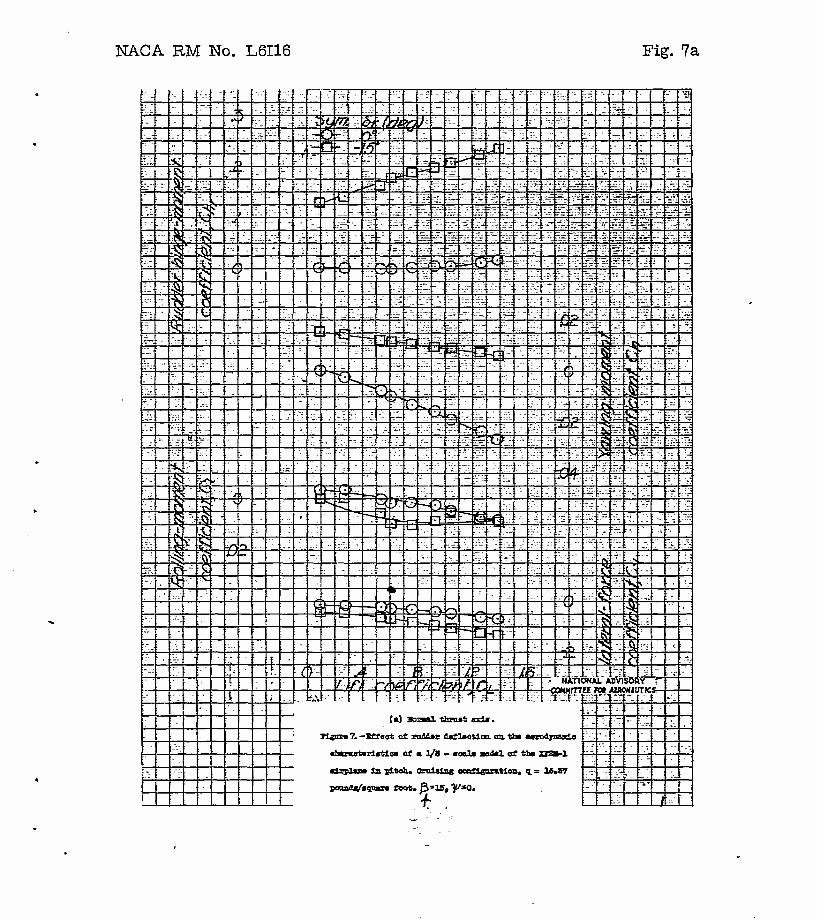
for trim through the flight range. A sample figure showing the form in which the above tests were plotted iB given as figure 7-
Xn order to obtain the effect of skewed thru3t axis during ground run, testB were run with the model set at lero angle of att&ck and zero angle of yaw,and the components plotted on figure 8 were read for a range of propeller speeds. These tests were also used to obtain the effect of skewed thrust axis on aileron angle required. For computations down to zero speed in take-off, plots of N, Y, L, and SR against Teff are required. (See sample plot fig. 90
THEORY
The asymmetric yawing moment encountered in the power-on condition with the normal thrust axis is due principally to the vertical tail surface operating at an effective angle of attack other than zero, when the airplane is at ?ero sideslip. This change in effective angle of attack at the tail is a function of the rotational velocity in the slipstream (which in turn ia a function of the torque ccofflcient), the relative geometry of the slipstream and the tail, and the axial velocity at the tail. Other contributing factors are the effect of the slipstream on the '.Ting fuselage interference and the yawing moment produced by the propeller in pitch. This asymmetric yawing moment, which is negative for a right-hand propeller, has to be trimmed before a straight flight path can be maintained.
Skewing the thrust axis has the following actions which are beneficial for the reduction of rudder deflection necessary for trim:
A yawing moment is produced by the thrust acting at a distance from the center of gravity, as shown In figure h, which counteracts the yawing moment produced by the slipstream rotation. The yawing-moment coefficient increases with thrust coefficient and, therefore, is greatest at low speeds, as can be seen with the aid of figure 3- The skew of the thrust axis gives rise to an incremental side force in the plane of the propeller (fin effect). There is a corresponding incremental Bidowaeh at the vertical tail in the opposite direction. Both effeots add yawing momenta that augment the direct thrust moment caused by the skew.
Engine torque reaction causing the left wing to be depi'essed for right-hand propeller is tho main difficulty encountered in

N-ICLI RM NO. L6II6
aileron control during take off. This torque reaction is slightly annoying for landplanes hut is more "bothersome for single float seaplanes, helow take-off speed. At high speeds the engine torque faction is not particularly "bothersome. The skewed thrust axis directs the slipstream more over one half of the ving than the other, from which results an asymmetrical lift due to power counteracting the engine torque reaction. The skewed thrust axis is more effective flaps down "because the lift increment due to the slipstream over the wing is greater; it is also more effective at the high thrust coefficients associated with low speeds. (See fig. 3.)
METHOD OF ANALYSIS
Estimating Bequired Data in Absence of Wind-Tunnel Data
For the case with ,a normal thrust axis, the side wash at the vertical tail can "be estimated "by the method of reference 3 from which asymmetric C^, C-j, and Cv can "be computed from the vertical tail and propeller characteris-cics.
From data with a zero skew thrust axis estimations can "be made for a skewed thrust axis in which four additional factors must "be considered a3 follows:
1, Direct thrust of the propeller.
2. Side force on the propeller.
3- Change in sidewash at the tail.
h. The asymmetric lift created "by the slipstream passing over one wing half more than the other.
The direct thrust of the propeller affects Cy, C^, and C^
in the following manner:
1. Cy = T"c* sin 7
2. Cn = V ö./b
3- Cz = TCT sin y h/b
The difference in effective thrust coefficient "between the unskewed and skewed thrust axi3 is "believed to he negligihle.

NACA HM No. L6II6
The side force of the propeller also affects these three components as follows:
1. Cy = Cyp COB 7
3. C? = Cy cos 7 h/b
vhere h Is the vertical displacement of the center of gravity from the thrust line» An explanation of the other symbols is shown in figure U. Generally, the angle of skew is small; there-
fore it can he assumed that sin 7 = —2— and ccs 7 » 1.0. The 57.3
side force of the propeller Cyp can be estinated with the aid of reference k. The change in side wash at the vertical tail can also be estimated with the aid of reference k. Knowing the change in angle of attack of the vertical tail, the increments in Cy, Cn, and Qi contributed by the vertical tail are readily computed, as for the zero skew condition. The asymmetric lift produced by the slipstream (rolling moment) can bo estimated with the aid of reference 5 by first estimating the increment in lift on the wing and second estimating how far the slipstream is displaced laterally when it reaches the center of pressure of the wing.
The increments in Cy, Cn, and C, can now all be added to
the zero skew condition to obtain the skewed condition and the results plotted in a similar way to the plots obtained for wind- tunnel tests.
Estimation of Flying Qualities from Skewed Thrust Azis Data
Free flight. - For this condition all forces and moments must be in trim. When Cn i3 reduced to zero by rudder deflection, Cy is usually not quite zero, at zero sideslip. This small Cy can be neutralized by blinking the airplane so that a component of the weight is equal and opposite to Cy; or if the wings are held level
the airplane will sideslip slightly until Cy equals zero. The latter condition represents the manner in which airplanes are flown and is the condition assumed in this report.
Rudder and sideslip angles for trim can be obtained by cross plotting C!n againo*:- B
r, To obtain the correction due to
sidsslip the values of Cn. and Cy, are required from estimates
or wind-tunnel tests.

MICA HM Ho. L6II6
Once the rudder and Bideslip angles are known the asymmetric Cj may easily he ohtained from a cross plot of C^ against 8r making a correction due to sideslip vith the value of Ci^ acquired from estimates or -wind-tunnel tests. The valrie of C^ is then located on a plot of C-j against total Ba (ohtained from -wind- tunnel tests or estimates) to determine the total aileron deflection required for trim.
Particular caution is required with regard to Bigas since the control-surface deflection required to oppose the out-of-trim force cr moment must lie used instead of the control-surface deflection required to produce this out-of-trim force or moment.
Inclusion of ground reaction (landplane).- For the present report the airplane was assumed to he maintained in a level condition (a = 0) for the entire ground run. Tail-wheel reaction ras assumed zero and computations were made for only the conventional landing 3ear. A coefficient of rolling friction of 0.02 end ?ero sideslip -were assumed. 'It -was also assumed that no "brakes vere used to help correct asymmetric yawing moments.
Although no rudder deflection data vere ohtained for the flaps-deflected condition, the data for the flaps-up condition are "believed to he applicahle within reasonable accuracy since the presence of the ground prevents the slipstream from being greatly deflected downward hy the flaps.
It was found that the free-flight rudder cnglos vith wings level trim did not fair smoothly into the rudder angles with ground reaction at zero angle of sideslip. For this reason it ia "believed that a transition period occurs "between T5 and 85 miles per hotir in which the "behavior of the airplane is dependent on the actual flight tests of the airplane in question and is indeterminahle from wind-tunnel tests.
Inclusion of water reaction (single-float seaplane)._ Vor the present report the seaplane was assumed to "be at tero angle of banSc and the ailoron angles required to maintain the level condition were computed. The rudier angles on the seaplane are net given since they are substantially the sama as for the landplans. The water reaction was assumed to produce' no yawing moments since the single main float is directly "below the center of gravity with wings level, which also means "both, wing tip floats would he out of the watez*.
Data were ohtained for flapB neutral and deflected, in this instance, since flap deflection has a pronounced effect on the

10 NACA HM No. L6H6
lift Increment produced by the slipstream and hence the rolling moment, 'with a skewed thrust axis.
DISCUSSION
Effect of Offpet Fin and Skew on Rudder Control
Estimated effect on XE2M-1 airplane.- The effect of skewed thrust axis on rudder control is presented in figure 10. Trimming the airplane at zero sideslip on the ground and calculating the effect of ground reaction, it is shown (fig. 10) that with the normal thrust axis the rudder control available is insufficient at low speeds, whereas with the skewed thrust axis the rudder deflection required is reduced considerably. Above cruising speeds the skewed thrust axis has a negligible effect on rudder effectiveness.
Effect on F6F-3 airplane.- In general, the results obtained from flight tests of the I6F-3 airplane have the same trend as those estimated for the XF2M-1 airplane. Data of figure 11 indicate the distinct advantage of the skewed thrust axis which is the reduction of rudder angle required for trim throughout the speed range, with power on. However, with windmillino: propeller the effect of skewed thrust axis is negligible. Offsetting the fin has no effect on the variation of rudder angle required for trim with speed, although with power en the curve is displaced in such a manner that the rudder angle required for trim is roduced at low speeds. With windmilling propeller the offset fin has a detrimental effoct on the rudder angle required for trim throughout the speed range.
Effect of Skewed Thrust Axis on Aileron Control
The data (fig. 12) Indicate that the skewed thrust axis reduces the aileron deflection required for trim at low speeds end has a negligible effect at high speeds, with flaps up. It is believed that with flaps deflected the thrust axis was excessively skewed which resulted in reversal of aileron deflection required for trim of the same magnitude, at low speeds. A skewed thrust axis of approximately 3° wotild be a happy medium and would reduce the aileron deflection required for trim at low speeds. At high speeds the offect of skewed thrust axis is negligible, with flaps deflected.

I7ACA HH No. L6II6 11
Miscellaneous Effects of Skewed Thrust Axis
Stability and vibrations.- The skewed thrust axis is believed to have no adverse effects on longitudinal, lateral, or directional stabilities. However, it may cause the vertical tail to stall at a different angle of yaw, with power on.
normally an airplane flies through lar^e angles of yaw and pitch and no propeller vibration difficulty has "been encountered; therefore, it is "believed that no sericua vibration problem, will have to "be overcome with a skewed thrust axis.
Performance.- T-fith the thrust axis in the skewed position the propeller is at an angle of yaw when the airplane is at zero sideslip. In this particular case the angle of yaw is 5° and from figure 13, which was prepared from date, of reference 6", it is shown that for 5° of yav the propeller efficiency decreases ahout 1 percent. A 1 percent loss in efficiency causes a loss of 2.0 niles per hour at a speed of -;0O miles per hour,
•When operating at high speeds, the change in section blade angle of attack due to the skewed thrust axis causes a reduction in the critical tip spaed of the propeller (reference 7)? there- fore compressibility effects will occur at a somewhat lower speed.
Vertical tail loads.- T7o data were obtained from which vertical tail loads can be calculated for tho skewed thru3t axis; therefore an attempt has been made to obtain an indication of the vertical tail loads. From figure lit- it is believed that the tail leads will probably be less with the skewed thrust axis than with the noixial thrust axis.
Rudder pedal foi'ce in dive.- Calculations based on hinge moment data indicate (fig. 15) that the rudder forces required in a high-speed dive condition will probably be less with the skewed thrust axis than with the normal thrust axi3.
COITCI/JSIOIK
ITrom the estimated and experimental results obtained with the skewed thrust axis, the following conclusions can be drawn:
1. The rudder deflection required for trim was reduced considerably at low speeds with the skewed thrust axis.

12 MCA RM Ho. L6II6
2. Estimations made for a single-float seaplane revealed that the skewed thrust axis reduced the aileron deflection reqtiired for ti-im with flaps up. With flaps deflected the thrust axis was "believed to "be excessively skewed, thereby producing a reversal of aileron deflection required for trim of the same magnitude as that obtained for normal thrust axis'.
3- The data Indicated that the rudder forces required In a high-speed diva and the vertical tail loads obtained will probahly he leas with the 3kewed thrust axis than with the normal thrust axis.
Langley Memorial Aeronautical Laboratory national Advisory Committee fcr Aeronautics
Langley Field, Va.

MCA HM No. L6II6 13
PJSET3ENCES
1. Phillips, V. H., Crane, H. L., and Hunter, P. A.: Effect of Lateral Shift of Center of Gravity on Rudder Deflection Required for Trim. NACA EB Eo. LU-IOo, igkh.
2. Gray, W. H.: Vlnd-Tunnel Tests of Two Hamilton Standard Propellers Embodying Clark Y and NACA l6-Series Blade Sections. KAGAME, Aug. 20, 19^1.
3. Purser, Paul E., and Spear, Margaret F.: Tests to Determine Effects of Slipstream Rotation on the Lateral Stability Characteristics of a Single-Engine Lcw-*.Tin& Airplane Model. NACA TN No. Ilk6, ±9k6.
U. Ribner, Herbert S.: Notes on the Propeller and Slipstream in Relation to. Stability. NACA ARR No. L*H12a, 19^.
5. Goett, Harry J., and Pass, H. P..: Effect cf Propeller Operation on the Pitching Moments of Single-F.ng1.ne Monoplanes. NACA ACR, May 19*H.
6. Runckel, Jack F.- : The Effect of Pitch en Force and Moment Characteristica of Full-Scale Propellers of Five Solidities, NACA ARR, June 19^2.
7. Pendley, Robert E.: Effect cf Propeller-Axis Angle of Attack on Thrust Distribution over the Propeller Disk in Relation to Wake-Survey Measurement of Thrust. NACA ARR No. L5J02b, 19^5.

NACA RM No. L6I16 Fig. 1
Relative wind
Figure i. . - System of axes and control-surface hinge moments and deflections. Positive values of forces, moments, and angles are indicated by arrows. Positive values of tab hinge moments and deflections are in the same directions as the positive values for the control surfaces to which the tabs are attached. NATIONAL ADVISORY
COMMITTEE FOR AERONAUTICS

Figure 2- Tfirce- v*w of r/?e !/^C(7/e ZESPL"»•**!
« CO
Elevator Hinge § O >
8 """ °f •». xreM-i Ktor ~ «

•l f n pe ̂ '": MM
.;•• V ; -"'III!,* • II '!" j! -. :. • J' - 1 '
!J. •'.'•'
1 .' II,I 11-
\ "T }'•'• '^r T" ,.- -'-
3v -I
',: • .' .: ,.. :\'.r. .'. ! ' T. i- •1; :: • ;. ' 'i. •[; .1 :!.
•|
'- •\- t
•• \ •r. r*r J '
i j n T •;»i
1 • ,: .] •.
\i ! •^ tH
«. :; .' 'i:- i"
'T < i i ,.\ * .w 1 ; K |.V" r\ "tf! w • »
Mi t \ r . ' S,
N .•;
|j- ,;' .i7* • i1 1 MJ 1 • ' 1
^ s. Tr / _ •4# fftti rK /^lO.TH '4L «*•
• j a * r A ;.. \
t v J .x'\ "- -.. •-,'? -iJTT *!
•/ *. s L V \ \ So T^ ^ %\ as mQr itEiHf 4i • N 1
i? '• :•'
• c H *' \ ̂ 1 X ^ •^, 'C
*1 1/; •«. *" "~i J» s > ^ ' .,• \
fl , • 5 VJ
, J o IT X i' -.:, ^ : \ i! ;'i • i1
t;:' •^ •s :v! •: V. 1 Ä
1 ^ j
!
w ) — 1
_i 7tws;
i i:, •?• :;••• !"' '!' y! lit •i"ir
::'l 'il'
' * i. ' ••.h 1 M I ' s : \ •r • i : -"-^ 7T' -M- ^ 1 r A $ /• A i.:; • 'r )'••
::,• ,1
(,l 1( I-- :.! ; ,y V'' ~ ••' , . :',M^ •*ri ^j $
iL D •S
£• T • !.
.! '• ;. % ' ; f •i £ ,[•
ill i • :: iil .' •:l '/'.'•• If U ':;i ;X r i if!' i. ii; '•. | f •!!'. ii
lilt •;:
:*••
,i ./. ,.] 1 •
^v. '•/
< h \ -^ • :; i ^ in •> ft s / •k
.;; : i,. 7-. -x • • M
1 •
1 ' • ' J
1
*r !^ * •::i •••I
i'" r' .i'i 1. ii': '* : r- ;; >ii| 'il' :'' ,j"
'. 1 •' USA 3
^ v 3 fe ̂ 0
•'• V ^ K •1; !t- !. \ 1 -p . • ,r
, •,• j J-" •\ •! i:=l '!': .V ̂ • K >.l. rl ::!l
T 1 ;.:l • |i :•.[ 1 I v: ; ' i. J | ,;: .il. ! V! \ V ^
*," "i .;•. •':
• ; • v' & /i| tf ^ A f\ .v';. " ;:l ä irf ö sf :;; \i\
:..:' i'^ <•
• J1
:•• •:f : i!'; '.}.'• :'; •!!;
;.t; i ;. "1 \ i!J .'i'i • !.r Vt' |i ' .;!! •i. ;','i :". •J«" t :;
^ JU f 5 I K "l
.4 X V '!'' . .• <ii r X •L . !': ''••! :- •
> • ••; <c b' '
JÖ •:i
f* n4 -r^ 1 1* ':; lt+4 • "• }<
, 1 •7 A
** 1\ s w. i- :ijl —^i
t\ £• '•••
^ N >* TJ
;;l i ii:, !]•! rii . :i'
d ä i.i1 in; lin
•J:
3P 17Ü _J -ii »-T ^44 •!'• ^k 4 * tf Öi 1 f
4» ss; ir 4 = ** 'ß. 1« irl 1 T^ "^ —*- 1 !'
M: ];••
1 1 1
W* t^t t. ^ Kir -4; rr
»'• .ii1 si .„ 4^
il .••1
i+rt tn-
j'H. -TT Ü1T -ft
fil L' * I /'
^ ; 1 *t \- ,1
7t" i-
•rft ,•1. I I'-. i.i
;i. •;' :r^ür 'S
•ü !'' •!.l ft . _|' "\ j. , f! .•I ;;' :[ 'I! 1.. •j1
;j :•: !'.'. 1 • ,i,: t'.: f^ ^V ;•;•• • :l
1 1 :!i • ;!'• .-; • •]
-T- r— F *« >
"tf •**: 4^ L, :; J-;
!' '•*- "i rr. rt* >*T *VH T*
i, 1 .1
rrlr /I 41 :i;' Kt * B i~. H4+ P^ ^w "*T" _i. JH -^
— ^ h t < ̂ & -4- " --•ft hnOi -T t*+^ •* -^
• •:•
r**- ri r* Ui H4- w^ titr '-*» •^ f+h- :F,
^*- uli ft* &, 4U K ! :
•f-t "^7
;tM & ta sJ •7
44 +yl it:
,i'' ^^ *> — -4.
s il* f ij i :i ?, *(;;!: '„4 ?; iß i ;•;; A f •'1
l''i •^ ifti ;.!! r.y [/; if? $ W i II 'ii' i« fl I1 : (I If!} \',-\ iPi r? *^
»!!f \titiY) •;;, ?t> •il i=- i'li *<
1 * >. ̂ /• * 7« ? ^ /> 15 T/ =v W ' ^ ft. /i )* .!'; ! "i 'i'i '•'••: • i. • 1'
ill '? .1. :'li i ':_: K* • •[ : t. •• ••• v / • • • :;•: ifl i" tli
^ i HE H! !!!' '1^
Pimp« 1. - IrtlmMA Äu-MtertittLo» for th« XWM-l «lrpla» obtained VMh a «ma- OMMTTnm'iaS^ifi
'iii I 'iii J1 ;l- i ,-
blade HamUtoc BtanMro. pnpuitp «liH ib-MrMi aurou nsuon trorereao« e/. igOO bhp »t M« l«wl rith a propaUw qMed of ljlj rpa, D, 11.J5 ft; •. 839 m *tj b, 37-5 f*l 0fli 0,ci83.
, • ''•' '• * ',1 •M- ! .'. IC il
''I k !fi; I!I! fa ü.i riil i'i liH II' kill ;Ä iiu «ll lit;
1!' Fli ilH
i 1 |4; iai w

Fig. 4 NA.CA KM No. L6I16
p/rot pofnf far ^ tietr mg thrust axis
-norma/
skew eat
NATIONAL ADVISORY COMMITTEE FOR AERONAUTICS
Figure 4»- Diagram showing how the thrust axis was skewed, Vertical position of thrust axis remained fixed.

NACA RM No. L6I16 Fig. 5
-"?. ':'•>• J^Tr r-Jij •;-=j \~ = iVr H-: C-.;
'.T- ~ IT^- \Ht ~?r- ^i -T• ~". rri ^ r. ,'^t f=>' •:• !;'r r."i ^'_ P\T >r:
.-e: •:"r: if rst V" = "- 'V' :x THS lifi -i": li~ r;'-. rT^: "±LT a-- ;s= ttö^- ;=; fi\ ̂ ü- r.:- ^1 -•S: ^: ;-;; :_
".- ri_- th" <(• !V r- ~ •r: .^ c^~
It- •^ •:=: • ~^[ :& L~ i-i;
i- -rr rt+ tri
"FT- *::"- :-=^ rr 7* "•^l
i7^ ;z i~\ ".T; -^i1
iczi; S] m ~3 i--- ~£ CP F^
&£ ill JtT-i li-ii: i£Z r-V ".:• -t ••: /"- ::1
:^L_- i^ ''^ •^~ be I--
•=;--• —:•:
-i : "~ == .'-r ==! -"': .:-"; -V; — =V ~E " =•> :'-•. --*'• -\ :-ir -.-. T-!T V fj'"
_frj
=r ?-; fl B So :« Hh £_: ÜT" S-" \li~ i.i i:-^ r^i ^z Ä ^ r^i 3-: . £ rc~ —. -T- Si ~i "'. i:r L=: j4 r* L= äs
^' II ws> -".'• '•x; iff '-.-• i •T.\
T^ :Jr. t^ .'*"• E r^ n^ H- H ̂ N :Sf ?7 P 7 7^; W fe »a
Si ii*r F£ f£ Ä. IE St' -"^f ^jq Si lib. ;"_' :=• fc jrrr
^ i^r ^ trJ :'#- =£ H £-.=; r^ A m?/ f-' "^ ±~ ^r" '-".•?
in= T~ s? -L-- ;:\i r» =i -f1.- -z. "£= :lr:: 'r-H ..-.. L.-| u? + "
/j ^^ l-t- äti 2E' 1=? -'JE ^
{-A y* % ^f ril
r—- ff> 'f TT
:rirr F7« on ~s- fil ~-?r. ?'=': ~- ^ UJC - [^ -^i *:^ K 'i?' bfc: r= ;-i A-, i2ir ^ z-^
*^V ih
!~ r.r. 'M Ji ?» J?r IB ILT :S •^ •^? t5: £tL. £S ;-'_- '= L^ rf.i "rü -^T -J? ; J, ?^J ••-^t • ill
rfJ* :i = "^ 5r 3 s~ jf;ä •Sj l^'-L H
;-= e; i"- E^; • "'
7UI =T-'; y^ ;-.•; :S ^ -^ --. b-'ti ~S- :-i; ;:..U '.T:
•^
~\Tr tzc :.::= :iH .""•
? :V7. ':••
r=^ v~t r^I; Üf :% ^ ': i'-i •=" S" •i? r7d ~r .a :?.i: ^ ̂ :u ?- :-•-
~r? "! '^ h- "T= rlr Ü ""; üi:
•!•: •— 'TH *$ fö Eiri
^ Jfe :?:'' •••II. •LM k^ i^a r^r •z- V? <r -._-•' SK n ;~I :'•>: r'i; •~k i; -X- =fr. i^E ^J= •>i
-==r ZJ ̂ 5! ^. -^4 ~r ^ p ^ ^-.'. •^z ^ :y '„':
••.-•' •"0 ~. •.:
s El; TTf Fi* £££ '.-i ~:
—• rrj i"^ f^-"; /•.. ^ 4. S Ä :.=:' / --: :>•!» ^ /' -";•_
"=••• ::__••
;.-': ICr ~T ^3 5 5 —• e:'-Z-. S= r^: m "V
&7 •--
2~\j •- =- ==; h -.:: ^
irH & •fl WV\ V
i^; r? iw :.T. S! i..11
"i ^=- w rp i> i !".V :j"^' r^ vS r^ ^ ^--. A rrr .".T::
^ $ .v- M \a K» :•'. :^^ --71 "E rT f' '?= '^ f^T'
=-•- rT- -."- rr •.-
/ ;*~ i-;
r5 -^ ..'^T |fi Ssi :_~ ' Z-~ -1 i£ —T"- 7 T iS •H ̂ ll.
•=* &% r:" "-; \A si i^' r- £'-H ¥ 4 -•?! ^T<1 71 :•.-
^:; A XV
-^-^ •z: >: :-; :^£ f • S i^ -_--. -=• •^r J:-T i"; TT: f / «
/ .".: == *7 #< W
.;j^ 'i J"-
?"••
ST ^T- :-'.. T=r v:- =i 'J: -i J .=v. ;^ . •'-.
= X I §* W. —" '• i
-= F ^-;! ['-'/ a i-~" V 1?" ~? 7- ?••: -l - ~: •t" -i; ri L^ J = EJ ?=••
'.'J :Ü: •H —" ,:.~ ^ :--: ;- vi:
^ —-T -L {"• i:V i! :TT
'-'-• ~ir -rt; :~ Ttl: s^.. r- .;-. r"r :_-. y :'r'.^ :-'j r'jjf f. y "t: "
-'.• •-
I?i; ^
Lr£; "t> 7"ft -Ij: S '=£•_ ;-.i _-•; =3= .'rl> it: s= •--• u- »=.- ^S ;-•:
^ 0- tti; e= rj\ "T _.-; -•i r: ••.'-. i. "v :* st iV. V* r^=f S5 -t: .?r-
r^rl is Lf7 •5= J.± s ^£» s; ''.:•. Se
•y !^ ^ F-" .r£ ^ •.j-.- :.'A -*- • .^j
Si £= ;;=• E?i' ':C-5 :^i Ti, r ."VE, *~^ •T^
•"^ =s :-i ~ =K =s -:~r ^r bs ^£r ä =3 Üt.r ''f\ •-: • — & .j- .73
rt3 ^. —• •:V :-ri Ü iS vi r'":; "f- =i :.•=;
•^-. :~. 25?. ~= ^ -:.-. r.-.v: j=^ *y .r: 3^. £]_ ( P ^r -""-
Sf £« ?Tc Tr? -i>' ^ :~i ="=; SiJ ~ « ~~: s si i£ ]z:-' fr \-\ ry; ~7 «^ L:'- "- ••;
& •A >?'T* F" .-> ~£ *I£; AJ WE rü f=^ :^- .•-: ^~ i~? •?.•:: s<: :^ h '•-- =•=? • >• / - :
i& •?^ :; = ^ri: =-:•': il- s1 :-' :r"" ~r H=: 5~ ITT:
:."^: r-s ]4 :^: ~.': ?a irEr. ?^ •''.'" P :
•:• "•
"^ Ss s= ••.- ^1- —: -.-; A":
•.-' :v" .J"-; ~'r. r:;. A V." -•:. '-=.- :T / ~- •'-.'-_
c5i' fc irf /Ti1 Ffl -v :::-: Tik :^ -•.;: £• -rl -h ;;i -'.- -/ •*• ~ i=^ / -Ü. !r:. 1 *? !/ll V .3: =i' '-••* .':> rü .:~1. ~ = - i: p.~ vir" -V -~. -z- ^ ":"i ::- M -•
1, P • i
~= £ irä :S. -"•T Sfij ;^L ~~. vS t^ =- ü-ir •is Er FT;': ^•: :~zL ^£ ii •-:- L-j !^l* 0i 5H l?i T £ :rX ^ ÖC. ..'-,
~;. k -I' ?;; ^"; t=r "Hi -.•- ?.v :•- LS -^ =L« -i~ ^:^ j"2ir y r:"-i :.-. •ir. /? W IJT; ~ 4- •<;- SJ^. V
~\Li I'J #j W r^ .s: ̂ JZ: f= .'?': E= ~r ~ [id ~j LCi '•T? & 1L". ••'- •£ -~ :-3 3ir S? b. -: .> \'.~i :. ::
trr •- F~
>5 tyf -*? =•:• ••"
-•- ?s rj? E-- .. r- ~j '6, + : '""; r "v s *l
=^Z 7~- =.;:. -r- is ~. 'ii ü:- :.'-. si: i^i "H: ~t~ ^ :;>" £:. z: Z- J" -•/
/ •-•-. -::•:; -" • - :- -. 7"^ rf-:
.:•;
•Vj -:" y •---•,
/' -~i' ,> /
• -; •p* 'I -- •• •'-•
E- -i- .:::, ^ Ti 7/ t=-:i -i'! :l- t-.
:.-.; ""-' rlE •it ? ~: S jV
• r
-.-. ^ 4- ?: -^ A/ £/( /O 'J- :•:':• ;-;• S- v: y- = :.- ^ & •^ - ^ ~~:~ f _ 3 2F i>
i^_' f-.; '"•": fi
rL.-: :::. .f>: V^ ^ ~-T" >, rii : -. -^j ?.'• L~ r-. .-:t.-". •*?
•r :.r. *-'. =...-; " /:J- -:: ^"r- "- V b ;.=!•
y W- "j;" :<* e? -• "•-" •?:. "- • "J
t= / ni in r>- .^i ^ s Ä i^r p;- ii=. :K:. '- -^, '^11— ..-•. t •ri- 7 -;; / JL V ,- :=-"" p V r
."•; r- ~1
• f •Si •- !W -:.-/ /£ -,'r ^ \ 'i- M&' •|fl! JTI *n £~ T- ^f ̂ '£. :Xf- - > •
COHHITCEE FM UMJMUT KS,
i'k .-: / 7 -i -- ?SL ( '
, i"" -— ; fl -•-• .s o - ; 1 d ^) < r\ f r> 7 (0 \ 1 <7 Hv c /. / J /J w :.. J \J. 4 1/ o J C3 1/ / (J Ü
:. "=• )/ // r?t 7 #TI *r, ?«!?«
J f j • •• t r
Figure 5.- Brake horsepower represented for rarlous vlng loadings and model soslee.

AREA5 Sy ft
Wing area(ihcAtfity0MrrwB,/fyxJ/2/.se4fpe er/wsj "534.0 Tafai vertical tot/surface &r?4 23.4 Fwareafafoafooawjbj^/i&^fatoeeJ /44 ftoe&er a/ea aftofM/jpe Q. 0
4 I-"
en
3 Q >
id NATIONAL ADVISORY
COHHTTTEE m AEKWNITICS
Figure €.- Thrae-Ti« drawing of F6*-5 alrplont. IT1
o i—i
OS
NACA RM No. L6I16 Fig. 7a
• '1 K:-' - •"• .'-
'-•-. --H :\i •- - •if
•\.i .~." T «r .=-• 7:f -:'.' '-••- •: - :. "r-
• -
•v i ' %. ><> /Z« h M w '<? ̂ ' • -.. '
• - •_~ -— s ^ - -." —
"- " " -. n w rT f ~ - y '; •i "i •) _£, ±i ft >- § •:•: .".; 7:i-
s §••• J.
-• - , f T* L aj _J,
•'•'
-••
•''••
f.v --• . i.""
1
I- ;: "' t-r 7;: - k:i: w rit rJi Ä. ::* ;•.-. ,^- -i V
""-• j,. E j- rL T-- -1-: ~~- >- --- ~'r.: ••• %-• ;i.7 •=;• •v:
:=::• ^v I:; .-- [^:- •JC • ~
<3 •• f • '.•
i^,' •. • ^i: ;r-i V;-' :-:• . f j'-r rip" .:;i Ti r== i-V rlr; :V -T: TT —~ r . .V --. :.- .-.;' .:... :.-J :-:'-' •=•/ i^
•_-•: .r:; :--_: -..\ :-"' •fjj •T ~? 'Tr >"f- :••:- :•>
-.::' 'i : •: £ 4 ."•""- •;- r:r :~ E. -r ~ S":. i5E :•:= f-' v.r T.i. ."•I: • r~ "if :->:. !:=•• IrÜ L:^. ^r I--'. -T; r'--
T- ~ * '•-• - '"-: :=-' - ";- ili' •'• :-l IT' :~ =. r:"J- l-:-- •'•'•
:;.- •i J V •i c \ C s ~Y •v ^ 'Vf ̂ f^ iai—• «s ̂i ̂ :- =;. :::-. ;s. L"^ S7 ~": 'j ... \ \ -1 ) vl y,.
•tj JC J >o " .::•' .:•- I"T" : " •
i I S" .-_ ..."- ~'^: : r. . -: -;y •'"•
.-• HL-L
- i * ti - .-" ;•:•> "--" ••"r^- ':.,'; - i :- •'.-.
.-"•'"- Vv "-I". -•; $ tj :i r"-. :-. s --• -r-' • "
i« O Is •-i" •'-' :~ t t- •- "r i ';.-:
r"- ..-•-
:"••- t< f! r-T >" : " - • •;
.-_ tL Tf ̂ Fl ;-v. .:; "": .-.-_ :-" --. i* ;
:::.• 1 J- M •^ Ö-T i ~ :-.- ;_" e5 1^ ^;- - .- f! bit L. :IHT _:: .;: - vi- f S
i." : •
V, tl k '""" :-:":" -: :•>
^ ^
. - .- - . • . .- >
'^ ^:• --. -• -"- ••-: -- r:- s w - -." • " \ ̂ > •F
: - 1 - .-; ^ ti • :rJ
: ."^ i. .-rl i -j^ t •i 'B •_ ;V= :.r •' >!•'.
•y^" "*3K 1 :fe^ J:-: |i
:'••• •
••••: .- - - .- -^;- .- !> ; ": •r:'
i/ tl —". i t^ ;s k-. -:-: •V
"' :." 4a. ~"•
;'-: :."L T~: :i. •Jl' ̂ t3 Ü. :v; ;ii -_": 1 :fi '--": ::T '=•• :". •
.'..- -'.-: "\ . ;?-r "-.- :-z ; 1 "" ;"r.-" >s •W :- -• * [:=' - :
•-•"- :-: ": •- .^.
Yl it' Ü "-?' lr.- :- •~i. .:-:
J $ *-A K ' •
- - .::.- ^U T -": ":: - ~ y. SO > \ i ,L_ t L-
PI—. K •-^. vi. •-.. -:: ~ Iv: •J:_ "t :'•-
:-.' S
I. J L *•>», Ä > Ö ~~< '1 f?V :?: '_ ^ -'- -•r
-. 5? r" ^ • ^7*J - "T- T « p ̂ }- .J. ^ . :'.- : -- :.:- f:7^ .:.-: . iv s •
3- CJ •
: y- _-" ;• .- --- I • -;: •:' s* K -/> *•>
.; :::; •_^ ::i -- .";- •:--.
,-; J-. . .". ' :
*C 1" Ä X/ -.- S-" •"-•'- (V •N •i
Tr.. 1 r -Ö ."j - :?."."- ',':• 1. •v; '-: . i i :kj - •"-• - ••- L £ t> < :.-
•:•••' "t= f= -il u rv 'i
'- 4 J" «£ ...
•-.• -. -k P fe «= i £ v< —l
5 ^ G -ü llv | W ." t Li -T-^ £J T f" i -* ::".- •-• _, > L:.-_ fi ^ •
' • 1- f - f •".-•
ji •3$ ? :" ; .-. --; ;; i. J r >•-
^ t" I ?-; : ^ 3:
-J- it 5- -f •r
' L • *-, n ~< ¥> ft 7v 4 ?? »A /: if i;. NATIONAL A0V1 soar
-: • i j t >t •J $
£ ••_.£-.. L:^" .:! •
(•) kaal ttoo»t axis.
Ilp» 7. — Xffout at nliw d«fiMttan. an to* anodjiiulo
•haraotnlstlea of a 1/0 - «oel» aodal of «1M ZISH-1
«iTpltii» la pitch, qgolaiag ocnf Ignxatlcn,, i = 16.87
poamU/aqjMi» foot. ^"W» 3^*0.
T
. :•-: -.:-
. " •: :V •
•--' :• . • 1 r
-•
•. TtT •
i L:-" /

Fig. 7b NACA RM No. L6I16

NACA RM No. L6I16 Fig. 8a
Off
•03
-M
-.IS
-z
4
•OS
1
A3 £0 30 40 Ä? 60
Effecf/re ttiruat cosffia&rf, Tc'
falfforma/ thrust axis.
Ftgure Ö -Effect ofrvdter ctefteficn tritt» varying tftn/sr coefficients an Me aamdpxt/wc cf&nxter/st/cs of a Ve-scate mceteS of foe Xr£H-l a/rpto/K. Blacfg anfffs 15', OV/S//& configuroiion/X'CT.yr'Cr, q-escaMis/spft

Fig. 8b NACA RM No. L6I16
!
JO
05
-05
fe *
I -J -£
Ja
it
0 c>
-OS
-JO
10 Eß 3D 4.0 S.0 6.0
Effective thrust coe/fiae»/, Tc' ua p* —www
ItfSketvec? t/n/st ar/s
figure 6 - Concluded

NACA RM No. L6I18 Fig. 9a
«-
|
•s
-10
-15
SO
I
as
-s <
le-
ts
•a>
ZO AQ eo BO Effect/re ffrost, T,px//xts
Id Hormaf Mrt/sf axis.
too eo
^ige/re 9-£ffecf of rua&er a&flecfian mtAe sto/ic thrust canaittan on tne oeraafyno/n/c cfiamcferrstfcs of a '/sscate moa& of theKFSM-I airplane Btxte ana& /5°, crv/sina conflffi/rat/on, cc-<T,yi-CT,q-0 lt>s/sa ft.
!

Fig. 9b NACA RM No. L6I16
£0
IS
f0
-3
%
.24
je sj
.oa
-»
-/5
i
0 £0 40 fiO 80 CO ISO
Effect/re ffire/st, T, pou/xfr
(b) Stewed tilirosf oxn
Figure Q-Concfucfeet

tttrttttnl 'Itil M Inlfffl I MtttlHi 14 fl lTlU H- I l-fflTW l+H>H UM 1144II t-H-Br
i m KiiiiiMHuiiimiiiuiiiMHMn«Bii IIIFlallu1*Mi,>,l,VFlu!>l[k<•••-»»• •>••••• ubi••••••.. ^••••^•••••••1 • ••?•"• •••••«II*•••••*••• ••••kirka«t•>•••• j•••••• • »• •••• ••••••«»•
:y::H!H HHsH5!yj!H!:::aiä:Si!ljffiH!!:MIB|||Si^^
a!t HI H.iinH:KS5«: :t!i:|Si:äjB!ä^ :!:y^S4nllHintii!:i:Hri{3lH:HlHliKlw:i!^^ ;ufitn;iilial!l'iiiiHu3»:n:uiKSi'(knH!:M]iR!i :.-,knit:;iiim:ffj:i)j;-:iK::::i:::'r::'i:!ici::i::::»>.'irrt EtM5:::::ti«jr r.i:i:::::cic;:.t: •i,)::r::n::::.-::-Muc::::::5i::::: • ••H|iaaiui|»li| L« riniiBBii ••^W>'i> " fiiFinMiiiiiiriii w wg' UIIIII »•••••* ifH^MiUWiiityaii ,IPI*I • •••MIHU^H •••• i . JV ;••*•• •••••'•a*'J •••••,ipi»«iarjp<iii ui .••••• ••••.••••'•! •••»«•#•>•*.«•.••••••
:::g i:(:iUil!(m!lHur:ä!iii:::iii!:lj|i&i:rciil^
o
o #
IT1
a*
hi Mi
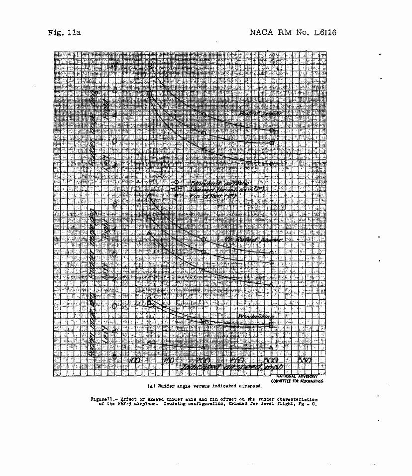
Fig. 11a NACA RM No. L6I16
"w^tf^p^ww^wrwwT
(a) Hudder angle rersue indloated airspeed.
HA'nOKM. ABVIWftV COHMinet FM MMNAUTKS
Pigureü.- Effect of skewed thrust axis ana fin offset on the rudder characteristics of toe P6F-3 airplane. Cruising configuration, trlmned for lerel flight, FR « 0.

NACA RM No. L6I16 Fig. lib

figure IS. - Sgtlaated Aileron deflection required for wing* level trla of the yfSK-1 airplane need ae a «ingle-float seaplane with noraal end efcewed thruit axle.
TO * I-1
>
o
as m

NACA RM No. L6I16 Fig. 13
Flgurel3.- Effect of yaw on propeller efflolenoy. Blade angle = 1^5° I obtained from reference 5J.

M *.
^»HmJi»4w;innimif>iotiMJtiiiFnpjii"MiiM'>|ift> t >HIJI»HHH.U*TH •.•• nnnnm» mM»iMnnm«<.j.f««iini mnn Mwllfito>.»^«a*IIMwiaW*<t*»Ut",hp«pii • «jit•§••*• • >...7.» J.MI .Mr J«,^ ••art ••Jiiihif ••»••;«>••£lanaliaafff• !•*• i M iln it»!«« *M • ••Ii*«Qt* iwiiiiwriMWpHininnniitiiatUiniiiiME.Mtiii««««! iui>fji»imitnii»Miruiii«ii[<i»*ii>irii«»tSiJiifnii«),fi «•iiiinhiiSiiitiEi'iiii
•aw mil it if •Itf>",l • •*•• f•(«•*"ra* f j» •«•••• •»•••••»•••••*•••••• iE314*a*llaiaf ••••"•••^••'••P« ••••••• •••••«••••-»• «•• ••!•••••••>•••••••*••••••«•••••••••••••«>••••••• l!W^II•l'n41Hf*<>>l,l^•*fllfIllal,l• «••'•••n«i«(*»HiJniiitiiiiMiiiHfiiHM(k«iiiiiiinMMHii|'l'l9l'aii"Mi»M<iljt riMiMiii*jfiiuM iwlH:iMKi!ti:uK:iKRWi&::::::^9iuu:".i:hn:Kt:u5:::ü^
a o
i-JjMI ^'W^^S* •rW:-^rl!^iTi"^^i1:
***?" ¥*ll. **?***** »l*sHp UKOH •jni»d 1B atmlcht night for tta XT2fcVl .lrriaM. IUO aenroi trim »1th tl» thrurt ud» 1B ncraO. and ibnd poaltionaj ornlplag sonflcarmtlon. ^^
o>

is!lllfflinlliiM.Ö
U^lliHllill* ••"••• I'Ft^^» • Ff •»•••hl'l1'TI'iihThll irtlilf * «••"••T*" EhlVl!hfePM>RyJ I •••••! HI ••**** ••• •*fc*x»" •••••••••• »PHli« *»••• PI ••*•»••••••»•• •••li»«h»fc*»B» •*•••••••• Htpiiiiiii»hiiuiiiiuMilll fflM91£liilll..£.lifofliffn^ nWUjr:i! t55!«EfIJilw:iB«U«]| nj::::j:Mi:::::!!Efi::p:tfi:!t:t::!:::::ü :;..a:.:a.j! ::::::::[;::::::::i:hs::::::::[i::^ iniuli.!W!ilUlul.tni.iraH.iM.^ t:::::::!i::c::::::u:KtJE:ii:r.RiKU]:: WllWiiiS Bli-Bälit!« RllOn»^
tuiiiiMiiniMk iMiji•••**• **•••• •••iiiii**pjMiiMl>ii"§d"iinihta«""""' -.J«-"-»«"^••*f ^••••^•••Hi'iill-W""»*"*-illlBiiii""Salü"l""3••• •••••• "-i wbb>«••••»• •*• MMI••*•••• ••••••••kin.•••••••• rlfiw fiLHi ii :h'*«':l( i f:rfP Sh,:HI<«i«d;""i!««iS,!Bll !"« fcHlttii 5>! !!">"!l Ki^:i:cK:::!W5!MI:sJ: cl:»:s.::::::::::::::t::t!R:>::i::::::i:K:::::::::;::::::i::::::: !KilUiHlHHUiUgE..a:....i.a.kKh.5.^ iBlM^«.«».^«..««.»«..!!!.«^ w«»|!Mi.y.o!l^
• WO ii|||lkn|aaa.lba|l«3.llBrDb3a)M<*lk|ltSaiaa ir«|l «»E^.taHa ••!••• ••••••••• •«{>•• <3 aHri|la2B.a •••(• Bk^ ••• •»Ejfiiill • |ltiifli •••2aaBa|i •••»«••«•I ••••!• .• aa aaaal aa aal aa> a* laTa laaaa. aaa rt . *aa •
• ll^lnUl^[•••!•• l"«l«'l"a*nM>*>Ha*ki>i*"«l*riUia*an Miiliiiu|livi>M>IHIM!"llliai,a ••IMIIIIII (Kni M ift\.al«H.bnid.alllli::mi.nn.iM.;aa..a^
il!vJ»r....fij'.>nlmi:tflfla.^^^ • iif.'iiaai»<ai v^ ' !••'•'• •• piaT
aiB«»-«a"ijiP*M"""aP"Pa!""""alaa-a"«»'""F^'"-,*""Ph"a-ia,BalB1**• ••••••••i*i*•••l,J•»ni•,••••-•a•a•,*"•••,'i••,*,,p,m•l•*^•••••••fc-a•*•,,'31 •'•^•'•(••••''('^'^•••U1!"'*«»-"*^"?•••••••••
[::Sliu:iiK!tu.i::iK;n r-Sfcxe»....^.^.^...»..!.!.........!^ maviiiiBuii• .-•-•,•-•• • a an- ••iiiiiiji«iiiiiiikii|iiwaii]tiii|ii|ibvpiiiuii>uyiii|iiu|iiiiiiii Hiiii<Hii||iiatiyiiiiiiii|iiiMwbi)UiiM*|ik lll*MiMi|||n||IFnF'iimip*'*111' ::.:j.j.::%|j H'-ia*:-! :....Uj1I-.:i...K..J:no>:^^ uw::iii!lcM.s.iiilaK.iH:n:£.iRin:K::i::!H({atN:aiii:H .::::::::n!:::t:suiK:i:K,::.::::::!nniiUi:r:i:::.:i:i::!.i5:::!i:J!:K!:!:iiia!iaJl i:::;:::::
.--•----•. -..—-.a- t^i|it»iiHtnnii-«BHMi|| nit nuiinill ilia"« I L m— iE~iiii--T-r--j.il - ii----- r —r~~ Tr~l — l -*- -• .ia-.— £—T — • a aaaaaiiM-aia3i?ID>pa r . p.« flat'J If U*'V]' 1 • * . •• • •H • E jIUI. »i, 7,| ta jiJilyliiii <* -, ta-.aa« ••••S< H ii.a •>•• • ••-..-'* •• .'f» i. •»•»•>* I •!( • f
r»IT*aa•ia-••-F a. »,, i*fi.n ••.wiaaa iBaariEriaBPiairkia.il> ill .•»-.!• a aihhul .iw • Jl s*>-il|Iallur aflr •r^Minni" ••-•.Ktji.itailiiiKii' • i. * -ÜB*.-., hi»-* •»-•I >J» i-alaf a -apaa •? in •' ••»{••*••* *b«< i lh tVjiaL-l laa-jr- --Pil-aT1 ]7BB*i • •••*( iM • •••BaiMaMi a •••••••B»BagiT|*a«tiBaBa,-M.,M
.:»iui:..:g...!...:..:i..ii:.nHW .'• '..iui.i::ii:::M.:::::::!::»u::::;H:Ki»:UK:n!:Ms:).::i:::::t ajlfMlJ*-4ttW tltntl BJTiTml IIÜJ4-UITi 11ll-i II11' 111\ I •' HUHUJillJlJmtJ
riguM 15. - tffwt of *k*v«4 thru«* «A« oa «itlaat«d oban«t*t4atlo« of mOtor vtQoirAd tor %riM in air» condition, flrniftag oonflgamtioa (oo-tprctiibilltjr effftot« •-toludtd).
55
I—I
*3 era
CJ1

TITLE: Effect of Engine Skew on Directional and Lateral Control Characteristics of Single-Engine Airplanes
AUTHOR(S[: Wallace, A. R.; Comenzo, R. J. ORIGINATING AGENCY:Natlonal Advisory Committee for Aeronautics, Washington, D. C. PUBLISHED BY: (Same)
OTO-1212B
(None) oaa. ocHcv NO.
RM-L6I16 rtlQlUKINO AOEHCT HO.
May '47 oocajus.
Unclass. cownnv U.S.
LAMOUAOI
Eng. r*wi iiuimtATioM) 32 I graphs, drwgs
ABSTRACT:
Advantages gained by skewed position of a single-rotating propeller of a single-engine airplane are demonstrated by estimated and flight tests results. The skewed thrust axis Is an effective method of overcoming Inadequate rudder control in low-speed powered flight, and It Increases aileron control, particularly with flaps deflected. Lower vertical tall loads and rudder control forces are attainable with skewed thrust axis.
DISTRIBUTION: Request copies of this report only from Originating .'gency DIVISION: Aerodynamics (2) SECTION: Stability and Control (1)
ATI SHEET NO.: R-2-1-34-
SUBJECT HEADINGS: Stability - Engine effect (89106)
Air Documonrs Division, ImaHiBoncs Ooparrmont Air Motor lei Command
AIR TECHNICAL I.'DES Wrlflhl- ottonon Air Feres Baso Dayton, Ohio