RESEARCH LABORATORY Three-Dimensional Gear Crack ... · Three-Dimensional Gear Crack Propagation...
15
NASA/TM-- 1998-208827 U.S. ARMY ARL-TR-1833 RESEARCH LABORATORY Three-Dimensional Gear Crack Propagation Studies David G. Lewicki U.S. Army Research Laboratory, Lewis Research Center, Cleveland, Ohio Ashok D. Sane and Raymond J. Drago Boeing Defense and Space Group, Philadelphia, Pennsylvania Paul A. Wawrzynek Cornell University, Ithaca, New York December 1998 https://ntrs.nasa.gov/search.jsp?R=19990019392 2020-03-10T07:38:32+00:00Z
Transcript of RESEARCH LABORATORY Three-Dimensional Gear Crack ... · Three-Dimensional Gear Crack Propagation...
NASA/TM-- 1998-208827
U.S. ARMY
ARL-TR-1833
RESEARCH LABORATORY
Three-Dimensional Gear
Crack Propagation Studies
David G. Lewicki
U.S. Army Research Laboratory, Lewis Research Center, Cleveland, Ohio
Ashok D. Sane and Raymond J. Drago
Boeing Defense and Space Group, Philadelphia, Pennsylvania
Paul A. Wawrzynek
Cornell University, Ithaca, New York
December 1998
https://ntrs.nasa.gov/search.jsp?R=19990019392 2020-03-10T07:38:32+00:00Z

The NASA STI Program Office... in Profile
Since its founding, NASA has been dedicated to
the advancement of aeronautics and spacescience. The NASA Scientific and Technical
Information (STI) Program Office plays a key part
in helping NASA maintain this important role.
The NASA STI Program Office is operated by
Langley Research Center, the Lead Center forNASA's scientific and technical information. The
NASA STI Program Office provides access to the
NASA STI Database, the largest collection of
aeronautical and space science STI in the world.
The Program Office is also NASA's institutional
mechanism for disseminating the results of its
research and development activities. These results
are published by NASA in the NASA STI Report
Series, which includes the following report types:
TECHNICAL PUBLICATION. Reports of
completed research or a major significant
phase of research that present the results of
NASA programs and include extensive data
or theoretical analysis. Includes compilations
of significant scientific and technical data and
information deemed to be of continuing
reference value. NASA's counterpart of peer-
reviewed formal professional papers but
has less stringent limitations on manuscript
length and extent of graphic presentations.
TECHNICAL MEMORANDUM. Scientific
and technical findings that are preliminary or
of specialized interest, e.g., quick release
reports, working papers, and bibliographiesthat contain minimal annotation. Does not
contain extensive analysis.
CONTRACTOR REPORT. Scientific and
technical findings by NASA-sponsored
contractors and grantees.
CONFERENCE PUBLICATION. Collected
papers from scientific and technical
conferences, symposia, seminars, or other
meetings sponsored or cosponsored byNASA.
SPECIAL PUBLICATION. Scientific,
technical, or historical information from
NASA programs, projects, and missions,
often concerned with subjects having
substantial public interest.
TECHNICAL TRANSLATION. English-
language translations of foreign scientific
and technical material pertinent to NASA'smission.
Specialized services that complement the STI
Program Office's diverse offerings include
creating custom thesauri, building customized
data bases, organizing and publishing research
results.., even providing videos.
For more information about the NASA STI
Program Office, see the following:
• Access the NASA STI Program Home Page
at http://www.sti.nasa.gov
• E-mail your question via the Internet to
• Fax your question to the NASA Access
Help Desk at (301) 621-0134
• Telephone the NASAAccess Help Desk at
(301) 621-0390
Write to:
NASA Access Help Desk
NASA Center for AeroSpace Information7121 Standard Drive
Hanover, MD 21076
NASA/TM-- 1998-208827
U.S. ARMY
ARL-TR-1833
RESEARCH LABORATORY
Three-Dimensional Gear
Crack Propagation Studies
David G. Lewicki
U.S. Army Research Laboratory, Lewis Research Center, Cleveland, Ohio
Ashok D. Sane and Raymond J. Drago
Boeing Defense and Space Group, Philadelphia, Pennsylvania
Paul A. Wawrzynek
Cornell University, Ithaca, New York
Prepared for the Fourth World Congress on Gearing and Power Transmission
sponsored by the Institut des Engrenages et des TransmissionsParis, France, March 16-18, 1999
National Aeronautics and
Space Administration
Lewis Research Center
December 1998

NASA Center for Aerospace Information7121 Standard Drive
Hanover, MD 21076Price Code: A03
Available from
National Technical Information Service
5285 Port Royal Road
Springfield, VA 22100Price Code: A03
THREE-DIMENSIONAL GEAR CRACK PROPAGATION STUDIES
David G. Lewicki
U.S. Army Research LaboratoryLewis Research Center
Cleveland, Ohio, 44135
Ashok D. Sane and Raymond J. Drago
Boeing Defense and Space Group
Philadelphia, Pennsylvania, 19142
Paul A. Wawrzynek
Cornell Fracture Group
Cornell UniversityIthaca, New York, 14853
ABSTRACT
Three-dimensional crack growth simulation was performed on a split-tooth gear design using boundary element
modeling and linear elastic fracture mechanics. Initial cracks in the fillet of the teeth produced stress intensity fac-
tors of greater magnitude (and thus, greater crack growth rates) than those in the root or groove areas of the teeth.
Crack growth simulation was performed on a case study to evaluate crack propagation paths. Tooth fracture was
predicted from the crack growth simulation for an initial crack in the tooth fillet region. Tooth loads on the
uncracked mesh of the split-tooth design were up to five times greater than those on the cracked mesh if equal
deflections of the cracked and uncracked teeth were considered. Predicted crack shapes as well as crack propagation
life are presented based on calculated stress intensity factors, mixed-mode crack propagation trajectory theories, and
fatigue crack growth theories.
INTRODUCTION
Gears used in current helicopters and turboprops are designed for light weight, high margins of safety, and high
reliability. However, unexpected gear failures may occur even with adequate tooth design (Couchan, et al., 1993). In
order to design an extremely safe system, the designer must ask and address the question "what happens when a
failure occurs." With regards to gear tooth bending fatigue, tooth or rim fractures may occur. A crack which propa-
gates through a rim would be catastrophic, leading to disengagement of a rotor or propeller, loss of an aircraft, and
possible fatalities (McFadden, 1985, Albrecht, 1988). This failure mode should be avoided. A crack which propa-
gates through a tooth itself may or may not be catastrophic, depending on the design and operating conditions. Also,
early warning of this failure mode may be possible due to advances in modern diagnostic systems (Kershner, et al.,1997).
One concept proposed to address bending fatigue fracture from a safety aspect is a split-tooth gear design
(Drago, et al., 1997). The prime objective of the split-tooth design is to control crack propagation in a desired direc-
tion such that at least half of the tooth remains operational should a bending failure occur. However, the split-tooth
design should have the same weight, performance, and reliability characteristics as a conventional single-tooth
design. Finite element models were developed to evaluate candidate split-tooth designs. These designs incorporated
grooves through the center of the tooth face widths to 'split' the teeth. Stress, strength, durability, and sliding veloc-
ity studies were performed to demonstrate the feasibility of such a design.
The objective of the current study is to analytically validate the crack propagation failsafe characteristics of a
split-tooth gear. A specially developed three-dimensional crack analysis program was used which was based on
boundary element modeling and principles of linear elastic fracture mechanics. The effect of the location of initial
cracks on crack propagation was evaluated. Crack growth simulation was performed on a case study to evaluate
crack propagation paths. Predicted crack shapes as well as crack propagation life are presented based on calculated
stress intensity factors, mixed-mode crack propagation trajectory theories, and fatigue crack growth theories.
NASA/TM--1998-208827 1

I. ANALYSIS
A. PreviousFiniteElementModeling
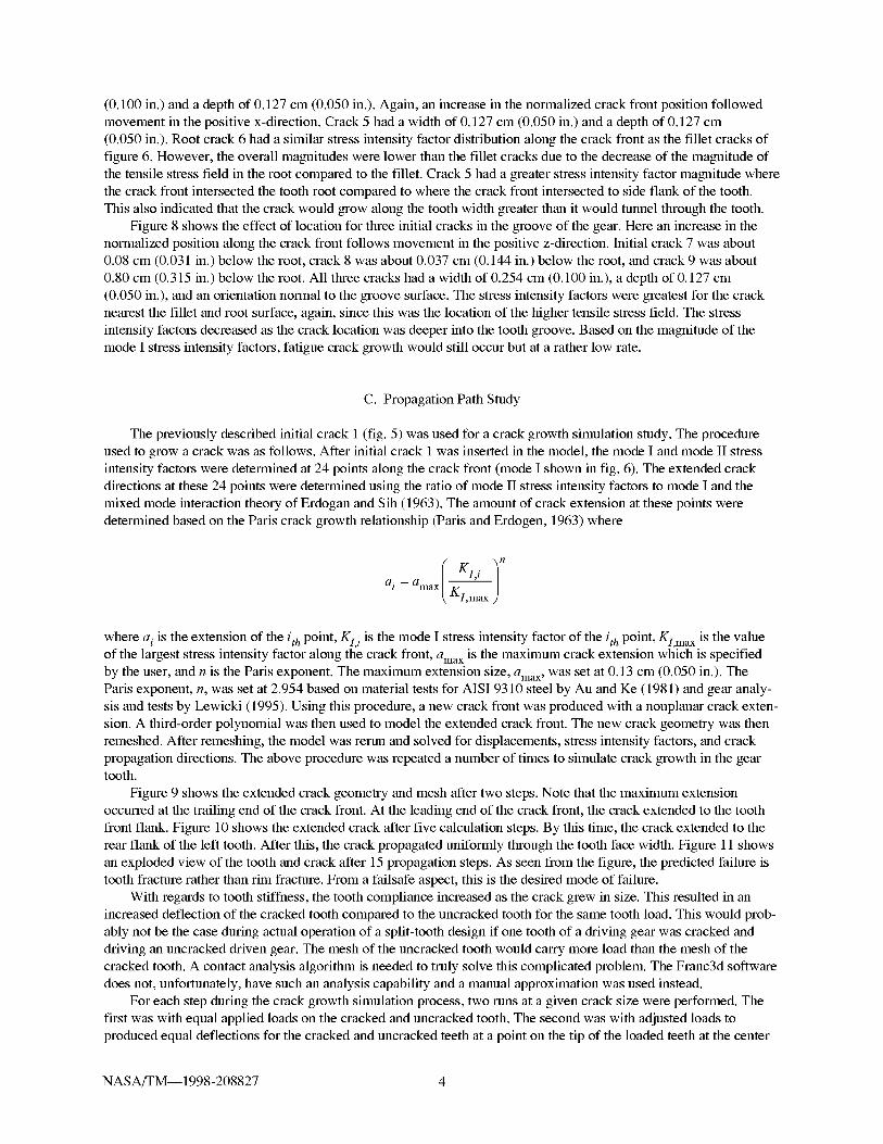
Aninitialstudywasconductedtodeterminethefeasibilityofasplit-toothdesign(Drago,etal.,1997).Here,analyticalmodelingwasperformedonaproposedgrooveddesignforthesungearofacommercialhelicopterplan-etarysystem.Themodelwasconstructedandanalyzedusingcommercialavailablefiniteelementmodelingtools(P3/Patran,1993,MacNeal,1981).Themodelwasthreedimensionalandconsistedprimarilyof8-nodehexele-mentswithalimitednumberof6-nodewedgeelements(fig.1).Themodelhadatotalnumberof24,248elementsand30,900nodesandusedmultipointconstraintboundaryconditionstomodelthebearingsupports.Themeshwasrefinedforfouroftheteethforimprovedstresspredictionaccuracy.
Thepurposeofthesplit-toothdesignwastocontrolcrackpropagationinadesireddirectionsuchthatatleasthalfofthegearfacewidthremainsoperationalshouldafailureoccur.Thiswasimplementedbyintroducingagroovethroughthecenterofthefacewidthoftheexistingconfiguration.IntheinitialDragostudy,variousgroovewidthsanddepthswereanalyzedtodeterminetheoptimizedconfiguration.A detailedstressanalysisofthetoothfilletsandgrooveswasrequiredtoproduceastronggear,rim,web,andhubsystemforhigh-loadhelicopterapplica-tions.Thestudyshowedthefeasibilityofsuchasplit-toothdesignandsubsequentexperimentaltestsareplannedforthefuture.Thetestswilluseasingle-toothbendingfatiguespecimenandapparatusasdescribedbyLemanski,etal.(1969).Duetothis,thecrackpropagationstudiesinthecurrentworkwillmodelthesingle-toothbendingfatiguetestgear.
B. ModeloftheSingleToothBendingFatigueGear
Asplit-toothdesignwasdevelopedforfuturetestsinanonrotatingsingle-toothbendingfatiguetestfixture.Thetestfixtureloadsatooth(orinthiscase,thetwosplitteeth)onthetestgearatthehighestpointofsingletoothcon-tactthroughaloadanvil.Theloadanvilisconnectedtoauniversalfatiguemachinewhichdeliversasteadyandalternatingforce.Loadistransferredthroughthetestgearandreactedbyareactionanvilatalocationapproximately135°fromtheloadedtooth.Thetestgearhas32teeth,4.763module(5.333diametralpitch),25°pressureangle,15.24cm(6.000in.)pitchdiameter,and0.95cm(0.375in.)facewidthpertooth.Aboundaryelementmodelofasplit-toothdesignofanuncrackedsingle-toothbendingfatiguetestgearisshowninfigure2.Notethatfourseriesoffoursuccessiveteethareremovedfromthetestgeartoallowinstallationinthetestfixture.Thecompletegear,rim,andwebassemblywasmodeledaswellasremovaloftheappropriateteeth.
Themeshintheregionoftheloadedteeth(aswellasthelocationsoftheinitialcracks)wasrefinedforimprovedstresspredictionaccuracy.Themodelshowninfigure2had1816elements(both4-nodequadrilateraland3-nodetriangular)and1479nodes.Thematerialpropertiesusedwerethatofsteel(modulusofelasticity=207GPa(30x106psi),Poisson'sratio=0.3).Anappliedpressurealongnarrowpatchesontwosplitteethatthelocationofthehighestpointofsingletoothcontactsimulatedatoothloadnormalforceof24,541N(5,517lb)pertooth.Dis-placementsonthereactionteethaswellashalfoftheinnerhubdiameterwereconstrainedtozerotomodelthereac-tionanvilandhubsupportbearing.
C. FractureAnalysisModelingCode
TheFranc3d(FractureAnalysisCodefor3Dimensions,Wawrzynek,1991)computercodewasusedforcracksimulation.ThisprogramwasdevelopedatCornellUniversityandanexecutableversionisopenlyavailabletothepublic.Crackgrowthsimulationisthemainfeatureoftheprogram.Theprogramusesboundaryelementmodelingandprinciplesoflinearelasticfracturemechanicstoanalyzecrackedstructures.Thegeometryofthree-dimensionalstructureswithnonplanar,arbitraryshapedcrackscanbemodeled.Thesimulationprocessiscontrolledbytheuserthroughagraphicaluserinterfacewhichincludeswindowsforthedisplayofthestructureaswellasamenu/dialog-boxsystemforinteractingwiththeprogram.
Themodelingofathree-dimensionalcrackedstructureisactuallyperformedthroughaseriesofprogramsdevelopedatCornellUniversity.First,thestructuregeometrygridpointdatais importedtoasolidmodelerpro-gram.Here,appropriatecurvesandfaces(orpatches)arecreatedfromthegriddataaswellasaclosed-loopsurface
NASA/TM--1998-208827 2

geometrymodel. This surface model is then imported to the Franc3d program for boundary element model prepara-
tion. The user can then mesh the geometry model using 3 or 6 node triangular surface elements, or 4 or 8 node
quadrilateral elements. Boundary conditions (applied tractions and prescribed displacements) are applied on the
model geometry over faces, edges, or points. Initial cracks such as elliptical or penny shaped can be inserted in the
structure. After complete formulation, the model is shipped to a boundary element equation solver program. Once
the displacement and traction unknowns are solved, the results are exported back to the Franc3d program for post
processing.
II. RESULTS AND DISCUSSION
A. Stress Analysis of an Uncracked Gear
The purpose of the stress analysis of an tmcracked gear was: (1) to validate the mesh refinement for the loaded
teeth, and (2) to compare the boundary element analysis results with previous Boeing Helicopter finite element
analysis results. Previous studies have shown that accurate stress intensity factor predictions, and thus, accurate
crack path predictions, were obtained if the initial mesh without a crack produced accurate estimates of the maxi-
mum stresses (Lewicki, 1995). The exaggerated deformation of an uncracked gear under load is shown in figure 3.
As expected, the majority of the deflection was in the loaded teeth. The magnitude of the maximum deflection was
0.218 mm (0.0086 in.) at the tip of the loaded teeth. In addition, there was slight rotation about the gear rotational
axis. Also, there was slight separation of the loaded teeth (best seen in the front view) and the deflection was sym-
metric with respect to the groove.
The element-averaged tooth fillet stress distribution is shown in figure 4. For these results, an equal pressure
was applied to both the left and right teeth. However, the area of the applied load on the left tooth was about
1 percent greater than the right due to round off errors in the model formulation. Thus, the magnitude of the stresses
on the left tooth was 1 percent greater than the right tooth. The maximum value of the maximum principle stress was
1213 MPa (176) ksi. This occurred on the left tooth at the center of the face width and at an angle approximately 40 °
with respect to the tooth centerline. As with the deflections, the stress distribution was symmetrical with respect to
the groove. Finally, the overall stress distribution using the boundary element analysis was similar to that of the
Boeing finite element model.
B. Effect of Initial Crack Location
The effect of the location of initial cracks on mode I stress intensity factors were analyzed for a variety of crack
locations in the tooth fillet. Four initial cracks were analyzed, one at a time, with the same load and boundary condi-
tions as previously described. Figure 5 shows the detailed boundary element mesh for initial crack 1. Figure 6 shows
the mode I stress analysis factors for all four initial cracks. The stress intensity factors were determined as a function
of position along the cracks front based on the calculated deflections using the method of Tracey (1977). All four
initial cracks had the same shape, size, and orientation. They were all half-ellipse cracks with a width of 0.254 cm
(0.100 in.), a depth of 0.127 cm (0.050 in.), and an orientation normal to the tooth fillet surface. Cracks 1 and 2 were
on the left tooth biased toward the front and rear, respectively, while cracks 3 and 4 were on the right tooth biased
toward the front and rear, respectively. For figure 6, the normalized position along the crack front starts with a value
of zero at a position on the crack front toward the front of the tooth, then to a value of one following movement in
the positive x-direction. The stress intensity factor versus position curves were similar for all four initial crack con-
ditions. The stress intensity factors were greater near the ends of the crack front compared to the center. This indi-
cated that the crack would grow along the tooth face width at a greater rate than through the tooth. In addition, based
on the magnitude of the calculated stress intensity factors, a crack in a gear made of AISI 9310 steel material would
grow in fatigue when subjected to the modeled geometry, load, and boundary conditions. This statement is based on
data by Forman and Hu (1984), where they publish a stress intensity factor threshold of 3.2 MPa._/m (3.5 ksi._/in.)
and a fracture toughness value of 182 MPa._/m (200 ksi._/in.) for AISI 9310 steel.
Figure 7 shows the effect of location for two initial root cracks on the right tooth. Crack 5 is in the center of the
root at the forward edge of the face width while crack 6 is at the center of the face width. Crack 5 is a quarter-
ellipse crack while crack 6 is a half-ellipse crack. As with the fillet initial cracks, crack 6 had a width of 0.254 cm
NASA/TM--1998-208827 3
(0.100in.)andadepthof0.127cm(0.050in.).Again,anincreaseinthenormalizedcrackfrontpositionfollowedmovementin thepositivex-direction.Crack5hadawidthof0.127cm(0.050in.)andadepthof0.127cm(0.050in.).Rootcrack6hadasimilarstressintensityfactordistributionalongthecrackfrontasthefilletcracksoffigure6.However,theoverallmagnitudeswerelowerthanthefilletcracksduetothedecreaseofthemagnitudeofthetensilestressfieldintherootcomparedtothefillet.Crack5hadagreaterstressintensityfactormagnitudewherethecrackfrontintersectedthetoothrootcomparedtowherethecrackfrontintersectedtosideflankofthetooth.Thisalsoindicatedthatthecrackwouldgrowalongthetoothwidthgreaterthanitwouldtunnelthroughthetooth.
Figure8showstheeffectoflocationforthreeinitialcracksinthegrooveofthegear.Hereanincreaseinthenormalizedpositionalongthecrackfrontfollowsmovementinthepositivez-direction.Initialcrack7wasabout0.08cm(0.031in.)belowtheroot,crack8wasabout0.037cm(0.144in.)belowtheroot,andcrack9wasabout0.80cm(0.315in.)belowtheroot.All threecrackshadawidthof0.254cm(0.100in.),adepthof0.127cm(0.050in.),andanorientationnormaltothegroovesurface.Thestressintensityfactorsweregreatestforthecracknearestthefilletandrootsurface,again,sincethiswasthelocationofthehighertensilestressfield.Thestressintensityfactorsdecreasedasthecracklocationwasdeeperintothetoothgroove.Basedonthemagnitudeofthemode I stress intensity factors, fatigue crack growth would still occur but at a rather low rate.
C. Propagation Path Study
The previously described initial crack 1 (fig. 5) was used for a crack growth simulation study. The procedure
used to grow a crack was as follows. After initial crack 1 was inserted in the model, the mode I and mode II stress
intensity factors were determined at 24 points along the crack front (mode I shown in fig. 6). The extended crack
directions at these 24 points were determined using the ratio of mode II stress intensity factors to mode I and the
mixed mode interaction theory of Erdogan and Sih (1963). The amount of crack extension at these points were
determined based on the Paris crack growth relationship (Paris and Erdogen, 1963) where
Kl,i )n
ai = amax / K--_"-/_ l,max J
where a i is the extension of the ith point, K1,i is the mode I stress intensity factor of the ith point, Kl,ma x is the valueof the largest stress intensity factor along the crack front, areax is the maximum crack extension which is specified
by the user, and n is the Paris exponent. The maximum extension size, amax, was set at 0.13 cm (0.050 in.). TheParis exponent, n, was set at 2.954 based on material tests for AISI 9310 steel by Au and Ke (1981) and gear analy-
sis and tests by Lewicki (1995). Using this procedure, a new crack front was produced with a nonplanar crack exten-
sion. A third-order polynomial was then used to model the extended crack front. The new crack geometry was then
remeshed. After remeshing, the model was rerun and solved for displacements, stress intensity factors, and crack
propagation directions. The above procedure was repeated a number of times to simulate crack growth in the geartooth.
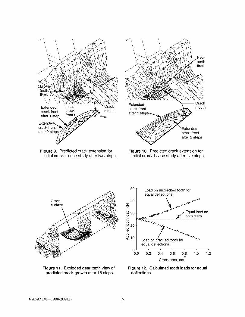
Figure 9 shows the extended crack geometry and mesh after two steps. Note that the maximum extension
occurred at the trailing end of the crack front. At the leading end of the crack front, the crack extended to the tooth
front flank. Figure 10 shows the extended crack after five calculation steps. By this time, the crack extended to the
rear flank of the left tooth. After this, the crack propagated uniformly through the tooth face width. Figure 11 shows
an exploded view of the tooth and crack after 15 propagation steps. As seen from the figure, the predicted failure is
tooth fracture rather than rim fracture. From a failsafe aspect, this is the desired mode of failure.
With regards to tooth stiftness, the tooth compliance increased as the crack grew in size. This resulted in an
increased deflection of the cracked tooth compared to the uncracked tooth for the same tooth load. This would prob-
ably not be the case during actual operation of a split-tooth design if one tooth of a driving gear was cracked and
driving an tmcracked driven gear. The mesh of the tmcracked tooth would carry more load than the mesh of the
cracked tooth. A contact analysis algorithm is needed to truly solve this complicated problem. The Franc3d software
does not, unfortunately, have such an analysis capability and a manual approximation was used instead.
For each step during the crack growth simulation process, two runs at a given crack size were performed. The
first was with equal applied loads on the cracked and uncracked tooth. The second was with adjusted loads to
produced equal deflections for the cracked and uncracked teeth at a point on the tip of the loaded teeth at the center
NASA/TM--1998-208827 4

ofthefacewidth.Thesecondsetofcaseswasaccomplishedthroughtrialanderrorbasedonthetrendingoftheequalloadscaseandadjustingtheappliedloadsuntilthecalculateddeflections(fromtheboundaryelementanalysis)ofthecrackanduncrackedteethwerewithin1percentofeachother.
TableI givestheresultsofthedeflectionsandtheloadsfromtheanalysis.Afterfivesteps(crackareaof0.263cm2(0.041in.2)),thecracked-toothdeflectionwas14percentgreaterthantheuncracked-toothdeflectionforthesameappliedloadoneach.After15steps(crackareaof 1.039cm2(0.161in.2)),thecracked-toothdeflectionwas220percentgreaterthanthatoftheuncrackedtooth.Figure12depictstheappliedloadasafunctionofcrackareafortheconstraintofequaltoothdeflections.Notethatatacrackareaof 1.039cm2(0.161in.2),theappliedloadontheuncrackedtoothisalmostfivetimesthatofthecrackedtooth.Thisresultingoverloadontheuncrackedtoothneedstobeconsideredinthefailsafedesignofsplit-toothconfiguration.
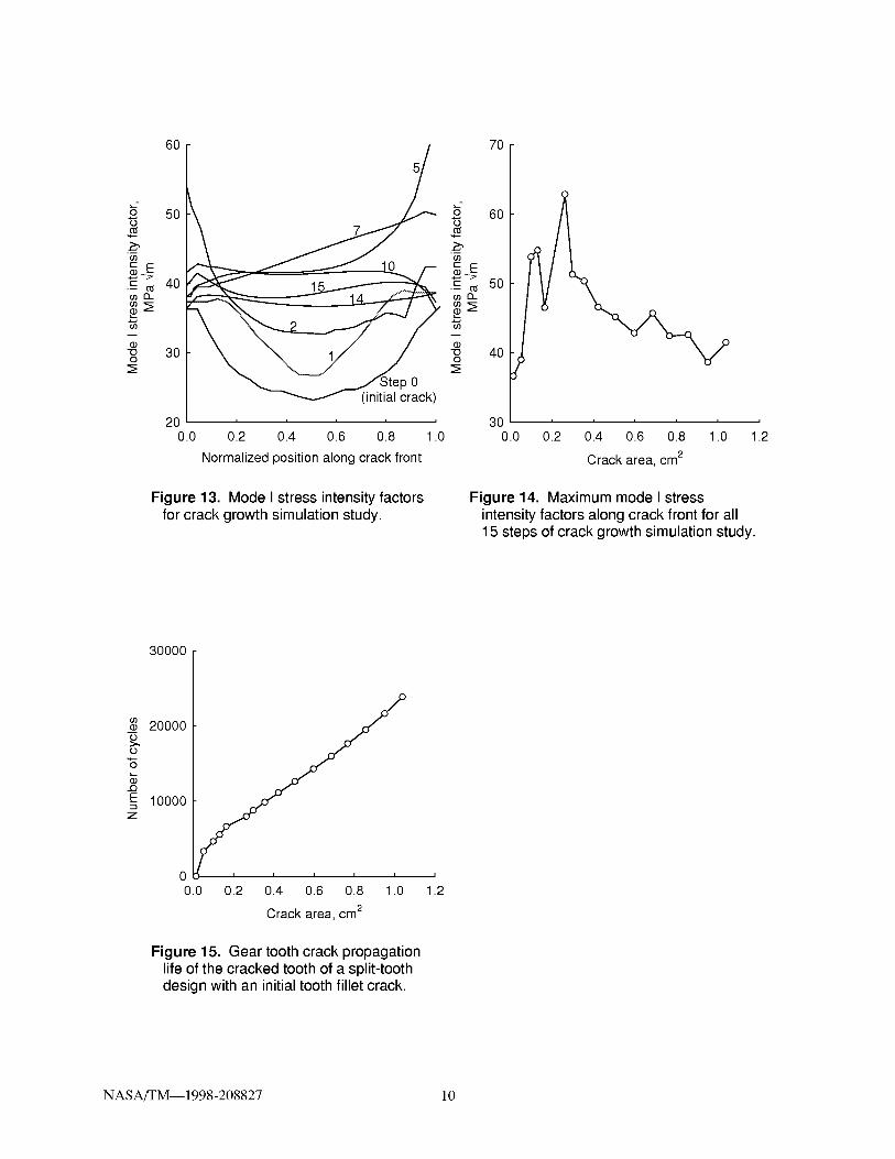
Finally,thepredictednumberof cyclesduringthecrackgrowthsimulationwasestimated.ThemodeI stressintensityfactorsasafunctionofthecrackfrontpositionforvariousstepsaregivenin figure13.Thenumbersonthecurvescorrelatetothestepnumber.Again,notetheincreaseinthevaluesofthestressintensityfactorsattheedgesofthecrackfrontfortheinitialsteps.Thisimpliedthatthecrackgrewin thetoothfacewidthdirectionatagreaterratethenthroughthetooth.Athigherstepsizes,thestressintensityfactorswheremoreuniformalongthefacewidthindicatinguniformcrackextension.Themaximumvalueofthestressintensityfactorsalongagivencrackfrontforagivencracksizeisshownin figure14asafunctionofcrackarea.ThiswasusedinthePariscrackgrowththeory(ParisandErdogen,1963)where
da C( AK in-_= \ 11
where da is the crack extension distance for dN number of cycles, C = 8.433.10 9, and n = 2.954 for AISI 9310 steel
material from Au and Ke (1981). Using the Paris theory, a typical life prediction for a cracked structure would
exhibit an exponential decrease in the number of cycles as a crack would grow at a given applied load. This is due to
the increase in the mode I stress intensity factor with crack size, and rims, decreased life. However, since the load on
the uncracked tooth was adjusted for equal deflections (i.e., decreased as the crack grew in size), the stress intensity
factors were nearly constant as the crack grew in size. This resulted in a rather linear increase in cycles with crack
area after an initial growth at the start of the propagation simulation.
CONCLUSIONS
Three-dimensional crack growth simulation was performed on a split-tooth gear design using boundary element
modeling and linear elastic fracture mechanics. The following conclusions were made: Initial cracks in the fillet of
the teeth produced stress intensity factors of greater magnitude (and thus, greater crack growth rates) than those in
the root or groove areas of the teeth. Tooth fracture was predicted from the crack growth simulation for an initial
crack in the tooth fillet region. This was the desired failure mode for an ultra-safe design. Tooth loads on the
uncracked mesh of the split-tooth design were up to five times greater than those on the cracked mesh if equaldeflections of the cracked and uncracked teeth were considered. The effect of tiffs needs to be considered in the
design of a split-tooth configuration.
REFERENCES
Albrecht, C., 1988: "Transmission Design Using Finite Element Method Analysis Techniques," Journal of American
Helicopter Society, Vol. 33, No. 2, Apr., pp. 3-14.
Au, J.J., and Ke, J.S., 1981: "Correlation Between Fatigue Crack Growth Rate and Fatigue Striation Spacing in AISI
9310 (AMS 6265) Steel," Fractography and Materials Science, ASTM STP 733, pp. 202-221.
Couchan, D.C., Barnes, G.K., and Cedoz, R.W., 1993: "Shot-Peened Gear Failures Due to Operation in a Mis-
aligned Condition," AIAA Paper No. AIAA-93-2147, June.
Drago, R.J., Sane, A.D., and Brown, F.W., 1997: "UltraSafe Gear Systems for Critical Applications - Initial Devel-
opment," AGMA TP-97FTM 10, Nov.
NASA/TM--1998-208827 5

Erdogan, F., and S ih, G.C., 1963: "On the Crack Extension in Plates Under Plane Loading and Transverse Shear,"
Journal of Basic Engineering, Vol. 85, pp. 519-527.
Forman, R.G., and Hu, T., 1984: "Application of Fracture Mechanics on the Space Shuttle," Damage Tolerance of
Metallic Structures: Analysis Methods and Applications, ASTM STP 842, pp. 108-133.
Kerslmer, S., Johnson, J., and Gamauf, M., 1997: "Sikorsky Support to Commercial Health and Usage Monitoring
Systems (HUMS): A Summary of Forty Months of Support," Proceedings of the AHS 53rd Forum, Virginia
Beach, VA, pp. 1233-1241, Apr.
Lemanski, A.J., Alberti, J.P., and Rose, H.J., 1969: "Evaluation of Advanced Gear Materials for Gear Boxes and
Transmissions," Report No. D210-10025-1, The Boeing Company, Vertol Division. Aug.
Lewicki, D.G., 1995: "Crack Propagation Studies to Determine Benign or Catastrophic Failure Modes for Aero-
space Thin-Rim Gears," Ph.D. Dissertation, Case Western Reserve University, May.
MacNeal, R.H., 1981: "Handbook for Linear Static Analysis," MSC/NASTRAN, The MacNeal-Schwendler Corpo-
ration, Dec.
McFadden, P.D., 1985: "Analysis of the Vibration of the Input Bevel Pinion in RAN Wessex Helicopter Main Rotor
Gearbox WAK143 Prior To Failure," Aeronautical Research Laboratories Report No. AR-004-049.
P3/PATRAN, 1993, P3/PATRAN User Manual, PDA Engineering, Costa Mesa, CA.
Paris, P.C., and Erdogen, F., 1963: "A Critical Analysis of Crack Propagation Laws," Journal of Basic Engineering,
Vol. 85, pp. 528-534.
Tracey, D.M., 1977: "Discussion of 'On the Use of Isoparametric Finite Elements in Linear Fracture Mechanics' by
R.S. B arsoum," International Journal for Numerical Methods in Engineering, Vol. 11, pp. 401-402.
Wawrzynek, P.A., 1991: "Discrete Modeling of Crack Propagation: Theoretical Aspects and Implementation Issues
in Two and Three Dimensions," Ph.D. Dissertation, Cornell University.
TABLE I. CALCULATED DEFLECTIONS FOR EQUAL LOADS AND LOADS FOR EQUAL DEFLECTIONS
Crack area,
cm 2 Load on Cracked
each tooth
tooth, KN deflectionnlnl
0.014 25,108 0.214
0.052 25,108 0.215
0.099 25,108 0.220
0.131 25,108 0.224
0.165 25,108 0.228
0.263 25,108 0.242
0.298 25,108 0.249
0.356 25,108 0.261
0.423 25,108 0.276
0.506 25,108 0.299
0.597 25,108 0.327
0.686 25,108 0.361
0.768 25,108 0.402
0.857 25,108 0.469
0.951 25,108 0.554
1.039 25,108 0.680
Equal loads Equal deflections
Uncracked Difference in
tooth deflections,
deflection, percentnlnl
0.212 0.9
0.213 0.9
0.212 3.8
0.212 5.7
0.212 7.5
0.212 14.2
0.212 17.5
0.213 22.5
0.213 29.6
0.212 41.0
0.212 54.2
0.212 70.3
0.211 90.5
0.211 122.3
0.212 161.3
0.212 220.8
Load on Cracked
cracked tooth
tooth, KN deflectionnlnl
25,108 0.214
24,950 0.215
24,207 0.216
24,009 0.218
23,788 0.221
22,473 0.227
21,730 0.229
20,758 0.233
19,765 0.239
18,420 0.246
16,960 0.253
15,292 0.259
13,884 0.266
12,132 0.277
10,434 0.286
8,621 0.294
Load on Uncracked Diffeience in
uncracked tooth deflections,
tooth, KN deflection, percentnlnl
25,108 0.214 0.0
25,266 0.213 0.9
26,009 0.217 33.5
26,207 0.217 0.5
26,428 0.218 1A
27,743 0.225 0.9
28,486 0.229 0.0
29,458 0.234 33.4
30,451 0.239 0.0
31,796 0.245 0A
33,256 0.252 0A
34,924 0.261 33.8
36,332 0.268 33.7
38,084 0.277 0.0
39,782 0.287 33.3
41,595 0.297 1.0
NASA/TM--1998-208827 6
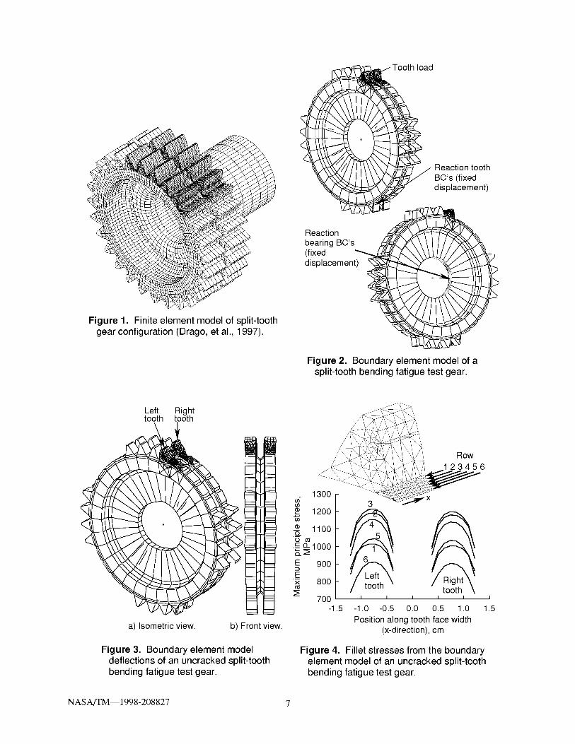
Figure 1. Finite element model of split-tooth
gear configuration (Drago, et al., 1997).
Reaction tooth
BC's (fixeddisplacement)
Tooth load
Reaction
bearing BC's
(fixed !
displacement)
Figure 2. Boundary element model of asplit-tooth bending fatigue test gear.
Left Righttooth tooth
13001200
1100
21000
E 900
E 800
:_ 700
-1.5
a) Isometric view. b) Front view.
Row
23456
X
toothI I I
0.0 0.5 1.0
Position along tooth face width(x-direction), cm
I
1.5
Figure 3. Boundary element model
deflections of an uncracked split-tooth
bending fatigue test gear.
Figure 4. Fillet stresses from the boundary
element model of an uncracked split-toothbending fatigue test gear.
NASA/TM--1998-208827 7

\Initial crackfront
Initialcracksurface
Crackmouth
0.254 cm
0.127 cm
Figure 5. Boundary element mesh forinitial crack 1.
40O
35_9
_3013...
-- 25"OO
Right\r \ _ooth_, ft
oor l'n rac 4__ _ear _;.
.,/::....... ...... ./'"
Initial crack 420 .....
0.0 0.2 0.4 0.6 0.8 1.0
Normalized position along crack front
Figure 6. Effect of initial crack location onmode I stress intensity factors; tooth filletlocations.
30O
•_ 25
.-IX.
-,_ 2o
"OO
+x
In Inltl_ en ok 8_6
15 .....0.0 0.2 0.4 0.6 0.8 1.0
Normalized position along crack front
.,9,oO
ffl
t--• -- t'_ffl IX.
"OO
15
10
0 i i i i i
0.0 0.2 0.4 0.6 0.8 1.0
Normalized position along crack front
Figure 7. Effect of initial crack location onmode I stress intensity factors; tooth rootlocations.
Figure 8. Effect of initial crack location onmode I stress intensity factors; toothgroove locations.
NASA/TM--1998-208827 8
Extended Initialcrack front crack mouth
after 1 ste amax
crack frontafter 2 ste
Reartoothflank
Extended _ Crackcrack front mouth
after 5 ste
crack front
after 2 steps
Figure 9. Predicted crack extension for
initial crack 1 case study after two steps.
Figure 10. Predicted crack extension for
initial crack 1 case study after five steps.
50 [ Load on uncracked tooth for
,_ | equal deflections
Crack z40 I
-_ 30 _ _ / Equal load on
o _ ___ both tee_th
,_10 I Load on clacked tooth for -"-o,,_
I equal deflections0 I I I I I I I
0.0 0.2 0.4 0.6 0.8 1.0 1.22
Crack area, cm
Figure 11. Exploded gear tooth view ofpredicted crack growth after 15 steps.
Figure 12. Calculated tooth loads for equaldeflections.
NASA/TM--1998-208827 9
O
"d
_9
_9
(D
"OO
D-
60
50
40
30
200.0
70
5
o 60z
if)
._ _ 5013..
-o 40O
..... 300.2 0.4 0.6 0.8 1.0 0.0
Normalized position along crack front
Figure 13. Mode I stress intensity factorsfor crack growth simulation study.
i i i i i i
0.2 0.4 0.6 0.8 1.0 1.2
Crack area, cm 2
Figure 14. Maximum mode I stressintensity factors along crack front for all
15 steps of crack growth simulation study.
30000
_9(D
>.,O
...(3
E
Z
20000
10000
00.0
i i i i i
0.2 0.4 0.6 0.8 1.0
Crackarea, cm 2
Figure 15. Gear tooth crack propagation
life of the cracked tooth of a split-toothdesign with an initial tooth fillet crack.
i
1.2
NASA/TM--1998-208827 10

Form ApprovedREPORT DOCUMENTATION PAGEOMB No. 0704-0188
Public reporting burden for this collection of information is estimated to average 1 hour per response, including the time for reviewing instructions, searching existing data sources,
gathering and maintaining the data needed, and completing and reviewing the collection of information. Send comments regarding this burden estimate or any other aspect of this
collection of information, including suggestions for reducing this burden, to Washington Headquarters Services, Directorate for Information Operations and Reports, 1215 Jefferson
Davis Highway, Suite 1204, Arlington, VA 22202-4302, and to the Office of Management and Budget, Paperwork Reduction Project (0704-0188), Washington, DC 20503.
1. AGENCY USE ONLY (Leave blank) 2. REPORT DATE
December 1998
4. TITLE AND SUBTITLE
Three-Dimensional Gear Crack Propagation Studies
3. REPORT TYPE AND DATES COVERED
Technical Memorandum
5. FUNDING NUMBERS
6. AUTHOR(S)
David G. Lewicki, Ashok D. Sane, Raymond J. Drago, and Paul A. Wawrzynek
7. PERFORMING ORGANIZATION NAME(S) AND ADDRESS(ES)
NASA Lewis Research Center
Cleveland, Ohio 44135 3191
and
U.S. Amly Research Laborato_2¢
Cleveland, Ohio 44135 3191
9. SPONSORING/MONITORING AGENCY NAME(S) AND ADDRESS(ES)
National Aeronautics and Space Administration
Washington, DC 20546 0001
and
U.S. Amly Research Laborato_2¢
Adelphi, Maryland 20783 1145
WU-581-30-13-00
1L162211A47A
8. PERFORMING ORGANIZATIONREPORT NUMBER
E-11436
10. SPONSORING/MONITORING
AGENCY REPORT NUMBER
NASA TM--1998-208827
ARL-TR-1833
11. SUPPLEMENTARY NOTES
Prepared for the Fourth World Congress on Gearing and Power Transmission sponsored by the Institut des Engrenages et
des Transmissions, Paris, France, March 16-18, 1999. David G. Lewicki, U.S. Army Research Laboratory, NASA Lewis
Research Center; Ashok D. Sane and Raymond J. Drago, Boeing Defense and Space Group, Philadelphia, Pennsylvania
19142; Paul A. Wawrzynek, Cornell University, Ithaca, New York 14853. Responsible person, David G. Lewicki,
organization code 0300, (216) 433-3970.
12a. DISTRIBUTION/AVAILABILITY STATEMENT
Unclassified - Unlimited
Subject Category: 37 Distribution: Nonstandard
This publication is available from the NASA Center for AeroSpace Information, (301) 6214)390,
12b. DISTRIBUTION CODE
13. ABSTRACT (Maximum 200 words)
Three-dimensional crack growth simulation was performed on a split-tooth gear design using boundary element
modeling and linear elastic fracture mechanics. Initial cracks in the fillet of the teeth produced stress intensity factors of
greater magnitude (and thus, greater crack growth rates) than those in the root or groove areas of the teeth. Crack
growth simulation was performed on a case study to evaluate crack propagation paths. Tooth fracture was predicted
from the crack growth simulation for an initial crack in the tooth fillet region. Tooth loads on the uncracked mesh of the
split-tooth design were up to five times greater than those on the cracked mesh if equal deflections of the cracked and
uncracked teeth were considered. Predicted crack shapes as well as crack propagation life are presented based on
calculated stress intensity factors, mixed-mode crack propagation trajectory theories, and fatigue crack growth theories.
14. SUBJECT TERMS
Gears; Crack propagation; Stress intensity factors; Safety; Boundary elements methods
17. SECURITY CLASSIFICATIONOF REPORT
Unclassified
NSN 7540-01-280-5500
15. NUMBER OF PAGES
1616. PRICE CODE
A03
18. SECURITY CLASSIFICATION 19. SECURITY CLASSIFICATION 20. LIMITATION OF ABSTRACTOF THIS PAGE OF ABSTRACT
Unclassified Unclassified
Standard Form 298 (Rev. 2-89)
Prescribed by ANSI Std. Z39-1B298-102


![CRACK PROPAGATION STARTING AT HOLE’S EDGE GROWING …€¦ · element method, the three-dimensional virtual crack closure technique [4]. It is also possible to use fracture mechanics](https://static.fdocuments.in/doc/165x107/605ef8521e3e3e426167ada4/crack-propagation-starting-at-holeas-edge-growing-element-method-the-three-dimensional.jpg)
