STUDY ON FAILURE CHARACTERISTICS OF GEAR … · STUDY ON FAILURE CHARACTERISTICS OF GEAR...
12
U.P.B. Sci. Bull., Series D, Vol. 80, Iss. 2, 2018 ISSN 1454-2358 STUDY ON FAILURE CHARACTERISTICS OF GEAR TRANSMISSION SYSTEM WITH CRACK FAULT Xin WANG 1 In order to investigate the characteristics of crack fault in a gear transmission system, dimensionless dynamical equations of the gear transmission system which contains a two-stage fixed-axis gear with crack fault and a one-stage planetary gear were established and solved by a numerical method. The bifurcation diagrams, phase diagrams, Poincaré sections and frequency spectrums in two conditions (normal and crack) is contrasted, so as to obtain the bifurcation characteristics of the system, and the failure frequency characteristics. The numerical simulation results are used to identify the fault of test rig. Keywords: gear transmission system, nonlinear dynamical, crack fault, bifurcation 1. Introduction Crack is a common fault of gear transmission system. The study of this kind of fault is one of the problems in the current gear system dynamics. At present, the research on the cracked gears has not been theoretical, and the failure model and analysis results are not accurate enough and need further study. In recent years, some scholars have studied the vibration mode, natural frequency and meshing stiffness of crack fault by finite element simulation [1-2]. However, the mechanism of crack failure needs to be studied though the nonlinear perspective. Ma Rui [3-4] established a torsional dynamic model of monopole gear with crack fault, and analyzed the dynamic characteristics caused by gear crack fault. Zhang Qingfeng [5] simulated the crack fault in tooth root by time- varying meshing stiffness, and established a nonlinear dynamic fault model with crack fault in tooth root. Wang Yangang [6] analyzed the nonlinear dynamic behavior of single-pair gear system under different fault parameters. In this paper, the research on the root crack is based on the monopole gear and lack of the research on the failure mechanism in the whole system. In the gear transmission system, the gears will be coupled with each other to make the crack failure characteristics changed. The research results of the monopole gear cannot be applied to the multi-stage gear transmission system. Therefore, it becomes very meaningful to establish the dynamic model of the multi-stage gear transmission system with crack fault, study the dynamic mechanism of the crack fault, and find out the characteristics of crack fault in the multi-stage gear transmission system. It 1 Dr., School of Mechanical Engineering, Baoji University of Arts and Sciences, Baoji, 721016, China, e-mail: [email protected]
Transcript of STUDY ON FAILURE CHARACTERISTICS OF GEAR … · STUDY ON FAILURE CHARACTERISTICS OF GEAR...
U.P.B. Sci. Bull., Series D, Vol. 80, Iss. 2, 2018 ISSN 1454-2358
STUDY ON FAILURE CHARACTERISTICS OF GEAR
TRANSMISSION SYSTEM WITH CRACK FAULT
Xin WANG1
In order to investigate the characteristics of crack fault in a gear
transmission system, dimensionless dynamical equations of the gear transmission
system which contains a two-stage fixed-axis gear with crack fault and a one-stage
planetary gear were established and solved by a numerical method. The bifurcation
diagrams, phase diagrams, Poincaré sections and frequency spectrums in two
conditions (normal and crack) is contrasted, so as to obtain the bifurcation
characteristics of the system, and the failure frequency characteristics. The
numerical simulation results are used to identify the fault of test rig.
Keywords: gear transmission system, nonlinear dynamical, crack fault,
bifurcation
1. Introduction
Crack is a common fault of gear transmission system. The study of this
kind of fault is one of the problems in the current gear system dynamics. At
present, the research on the cracked gears has not been theoretical, and the failure
model and analysis results are not accurate enough and need further study.
In recent years, some scholars have studied the vibration mode, natural
frequency and meshing stiffness of crack fault by finite element simulation [1-2].
However, the mechanism of crack failure needs to be studied though the nonlinear
perspective. Ma Rui [3-4] established a torsional dynamic model of monopole
gear with crack fault, and analyzed the dynamic characteristics caused by gear
crack fault. Zhang Qingfeng [5] simulated the crack fault in tooth root by time-
varying meshing stiffness, and established a nonlinear dynamic fault model with
crack fault in tooth root. Wang Yangang [6] analyzed the nonlinear dynamic
behavior of single-pair gear system under different fault parameters. In this paper,
the research on the root crack is based on the monopole gear and lack of the
research on the failure mechanism in the whole system. In the gear transmission
system, the gears will be coupled with each other to make the crack failure
characteristics changed. The research results of the monopole gear cannot be
applied to the multi-stage gear transmission system. Therefore, it becomes very
meaningful to establish the dynamic model of the multi-stage gear transmission
system with crack fault, study the dynamic mechanism of the crack fault, and find
out the characteristics of crack fault in the multi-stage gear transmission system. It
1 Dr., School of Mechanical Engineering, Baoji University of Arts and Sciences, Baoji, 721016,
China, e-mail: [email protected]
142 Xin Wang
also provides a solid theoretical basis for multi-stage gear transmission system
fault diagnosis.
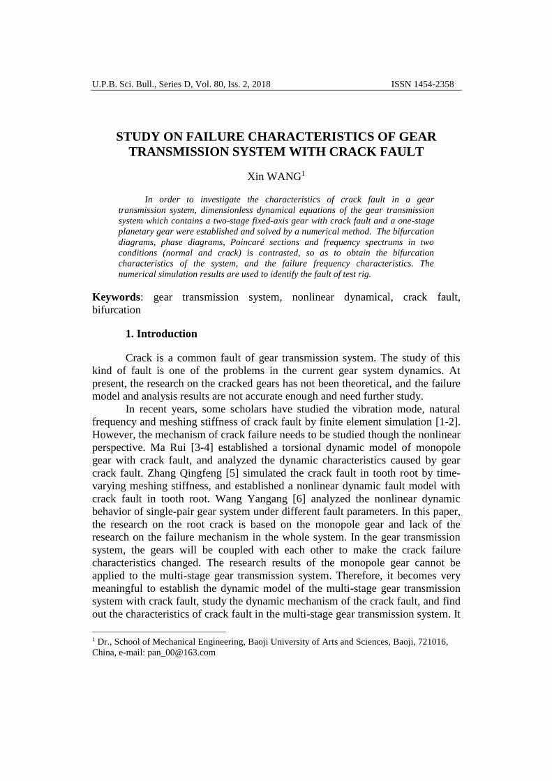
2. Torsional dynamic model of gear transmission system
The system studied in this paper is a test rig of gear transmission system
which contains a two-stage fixed-axis gear and a one-stage planetary. Where spur
gears 1, 2 compose the 1st stage fixed-axis gear for the input, spur gears 3, 4
compose the 2nd stage fixed-axis gear, the planet carrier is for the output. The
torsional dynamic model is established by using the lumped mass method as
shown in Fig. 1. The model does not consider the transverse vibration
displacement of gears. Gear meshing parameter is simulated with a spring and a
damper.
Fig.1. Torsional dynamic model of gear transmission system
here, θs, θc, θpn, θ1, θ2, θ3, θ4 represent the angular displacement of sun gear, planet
carrier, planetary gear n (n=1, 2, 3, 4), spur gears 1, 2, 3, 4, respectively.
Throughout this paper, the subscripts s, c, pn, r, 1, 2, 3, 4 denote sun gear, planet
carrier, planetary, ring gear and squr gears 1, 2, 3, 4. Quantities rs, rc, rpn, r1, r2, r3,
r4 are the base circle radius of gears. Quantities Kspn(t), Krpn(t), K1(t), K2(t) denote
the meshing stiffness of sun gear with planetary gear n, ring gear with planetary
gear n, 1st stage fixed gear and 2nd stage fixed gear. Quantities Cspn, Crpn, C1, C2
denote the damping of sun gear with planetary gear n, ring gear with planetary
gear n, 1st stage fixed gear and 2nd stage fixed gear. Tin is the input and Tout is the
output.
2.1 Motion differential equations of the system
Based on the Lagrangian equation, the motion differential equation of the
system shown in Fig. 1 is established on the basis of the clearance, the time-
Study on failure characteristics of gear transmission system with crack fault 143
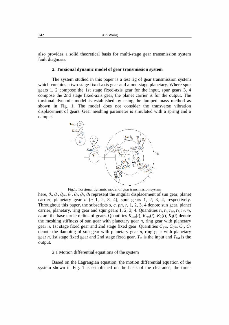
varying meshing stiffness and the comprehensive meshing error.
=−
=+
=−+
=+−
=+
==
=
out
n
rpnc
n
spnccc
rpnpnspnpnpnpn
n
spnsss
in
TFrFrJ
FrFrJ
FrFrJ
FrFrJ
TFrJ
--
0-
0
0
4
1
4
1
24
4
1
44
2312223
1111
(1)
Here, 3223 JJJ += ,
ss JJJ += 44, where J1, J2, J3, J4, Js, Jpn, Jc are the mass moments of
inertia of each gear on the shaft;
F1, F2, Fspn, Frpn are the meshing force of each stage on the meshing line,
( ) ( )iiiii xftKxCF += , (i=1, 2, spn, rpn);
xi is the relative displacement of each stage meshing line, (i=1, 2, spn, rpn),
)(122111 terrx −−= ,; )(244332 terrx −−= ,
)(- terrrx spnccpnpnssspn −−= , )(terrx rpnccpnpnrpn −−= ;
f(xi) is the clearance nonlinear function, (i=1, 2, spn, rpn), written as
−+
−
=
iiirpi
ii
iiii
i
bxbx
bx
bxbx
xf
,
,
,
0)( (2)
where, bi is half of the clearance, (i=1, 2, spn, rpn).
The time-varying meshing stiffness of the gear pair Ki(t) will be specified in 2.2.
The damping coefficients form as
)/1/1/(2
)/1/1/(2
)/1/1/(2
)/1/1/(2
43222
21111
pnrmrpnrpnrpn
pnsmspnspnspn
m
m
mmKC
mmKC
mmKC
mmKC
+=
+=
+=
+=
(3)
where, 1 ,
2 , spn , rpn are damping ratio and m1, m2, m3, m4, ms, mpn, mr
are the mass of each gear.
The comprehensive meshing error of gear pair using the 1st harmonic
form of meshing function, that is
)sin()( imiaii twete += (4)
Here, eai is the comprehensive meshing error amplitude of each gear, (i=1, 2, spn,
rpn), and i is the comprehensive meshing error initial phase of each gear, (i=1,
2, spn, rpn). wmi is the meshing frequency of each gear, (i=1, 2, spn, rpn).
Define time nominal scale wh, order twh= , where 11 emh mKw = .
144 Xin Wang
Dimensionless displacement is 1/bxx ii = , i=1, 2, spn, rpn. Dimensionless
excitation frequency is Ωi, hmii ww /= , i=1, 2, spn, rpn. Dimensionless
comprehensive meshing error amplitude is 1/ bee aiai = , i=1, 2, spn, rpn.
Dimensionless nonlinear function is:
−+
−
=
11
1
11
//
/0
//
)(
bbxbbx
bbx
bbxbbx
xf
iiirpi
ii
iiii
i
,
,
, (5)
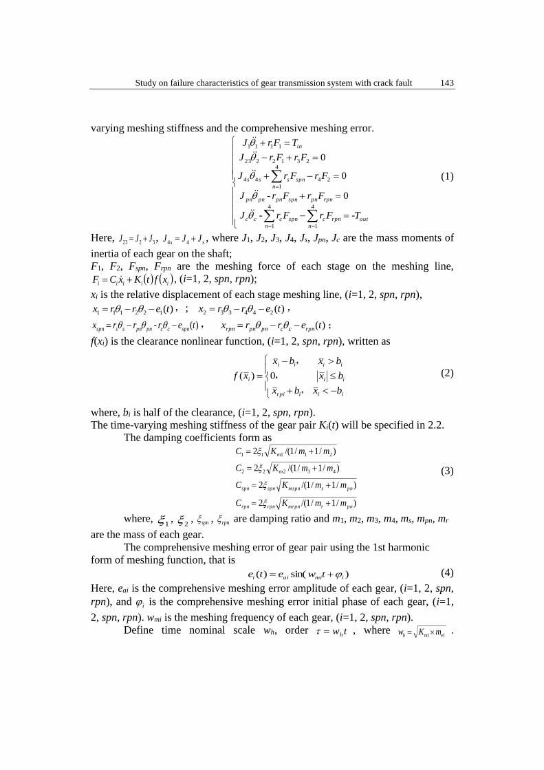
The equations are normalized, and the system dimensionless motion
differential equations can be obtained as:
( )( )
( )( ) ( )
( )( )
( )( )
( )( ) ( )
( ) ( ) ( ) ( )
( ) ( ) ( ) ( ) ( ) ( )
( )( ) ( )
( )( ) ( ) ( )
( ) ( ) ( ) ( ) ( )
++=−+−
++−+−
++=−
+−+−+
+++++
+=−−++−−
++=−−++
==
==
==
====
==
rpnrpnrpn
arpn
hce
outcrpn
n
rpn
hc
rpnrpn
hpn
rpn
n
rpn
hc
rpnrpn
hpn
spn
n
spn
hc
spnspn
hpn
spn
n
spn
hc
spnspn
hpn
rpn
spnspnspn
aspn
hce
outc
hsshss
rpn
n
rpn
hc
rpnrpn
hpn
rpn
n
rpn
hc
rpnrpn
hpn
spnspn
hpn
spn
n
spn
hc
spn
n
spn
hs
spnspn
hpnn
spnspn
hc
spn
n
spn
hs
spn
a
n
spn
hs
spn
n
spn
hs
spn
hehehehe
a
h
in
hehehehe
b
e
bwJ
TrxfK
wmxfK
wmxC
wm
xCwm
xfKwm
xKwm
xCwm
xCwm
x
b
e
bwJ
Trxf
wrm
Krx
wrm
Cr
xfKwm
xfKwm
xCwm
xCwm
xfKwm
xfKwm
xfKwm
xCwm
xCwm
xCwm
x
b
exf
wm
Kx
wm
Cxf
wm
Kx
wm
Cxf
wm
Kx
wm
Cx
b
e
bwJ
rTxf
wm
Kx
wm
Cxf
wm
Kx
wm
Cx
sin111
11111
sin-
11111
11111
sin
sin
2
11
2
4
122
4
1
4
122
4
1
2
11
222
4
242
4
24
4
122
4
12
4
12
4
12
4
4
1
4
14
22
2
2
1
24
12
4
4
1 4
22
3
22
3
212
2
11
1
12
11
2
1
1
1
1
2
1
122
2
22
2
212
1
11
1
11
(6)
where me1, me2, me3, m4s are the equivalent mass of gear, Jce is the equivalent mass
moment of inertia of gear,
2
21
2
123
2311
rJrJ
JJme
+= ,
32
232
rr
Jme = ,
2
34
2
423
2343
rJrJ
JJme
+= ,
2
44
s
ss
r
Jm = ; 2
cpncce rNmJJ += .
2.2 Mesh stiffness
Yang and Lin [7] proposed the potential energy method to calculate the
mesh stiffness of a pair of external–external spur gears by considering Hertzian
contact stiffness kh, bending stiffness kb and axial compressive stiffness ka. Later,
Tian et al. [8] introduced an additional term called the shear stiffness ks in the
potential energy method. Their expressions are more concise and clear in form
and easy to be programed, and therefore is used in this paper to calculate gear
tooth stiffness Kt. This method is also the most widely used method. Chen [9], Yu
[10], Anand Parey [11] and Liang [12] applied this method to calculate the gear
Study on failure characteristics of gear transmission system with crack fault 145
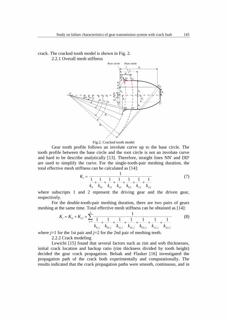
crack. The cracked tooth model is shown in Fig. 2.
2.2.1 Overall mesh stiffness
Fig.2. Cracked tooth model
Gear tooth profile follows an involute curve up to the base circle. The
tooth profile between the base circle and the root circle is not an involute curve
and hard to be describe analytically [13]. Therefore, straight lines NN' and DD'
are used to simplify the curve. For the single-tooth-pair meshing duration, the
total effective mesh stiffness can be calculated as [14]:
222111
1111111
1
asbasbh
t
kkkkkkk
K
++++++
= (7)
where subscripts 1 and 2 represent the driving gear and the driven gear,
respectively.
For the double-tooth-pair meshing duration, there are two pairs of gears
meshing at the same time. Total effective mesh stiffness can be obtained as [14]:
= ++++++
=+=2
1
,2,2,2,1,1,1,
21 1111111
1
j
jajsjbjajsjbjh
ttt
kkkkkkk
KKK (8)
where j=1 for the 1st pair and j=2 for the 2nd pair of meshing teeth.
2.2.2 Crack modeling
Lewichi [15] found that several factors such as rim and web thicknesses,
initial crack location and backup ratio (rim thickness divided by tooth height)
decided the gear crack propagation. Belsak and Flasker [16] investigated the
propagation path of the crack both experimentally and computationally. The
results indicated that the crack propagation paths were smooth, continuous, and in
146 Xin Wang
most cases, rather straight with only a slight curvature, similar to the findings in
Ref. [15]. It is pointed out by both Kramberger et al. [17] and Belsak and Flasker
[16] that the crack mostly initiated at the point of the maximum principle stress in
the tensile side of a gear tooth (critical area in Fig. 2).
The crack is modeled as a straight line from the gear tooth danger area, as
shown in Fig. 2. The crack propagates along the straight line until reaching the
tooth central line at point B. Then, it changes the propagation direction towards
point D where the tooth breaks. According to the state of the crack in the test rig,
only the state when the crack does not reach the centerline is studied, where q1 is
the crack length and the angle between the crack line and the tooth center line is
defined as .
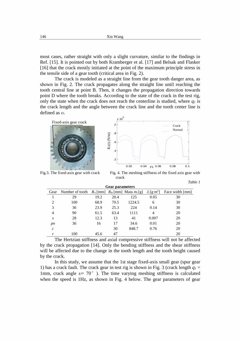
Fig.3. The fixed-axis gear with crack Fig. 4. The meshing stiffness of the fixed axis gear with
crack
Table 1
Gear parameters
Gear Number of tooth Rri [mm] Rbi [mm] Mass mi [g] Ji [g∙m2] Face width [mm]
1 29 19.2 20.4 125 0.05 30
2 100 68.9 70.5 1224.5 6 30
3 36 23.9 25.3 224 0.14 30
4 90 61.5 63.4 1111 4 20
s 28 12.3 13 41 0.007 20
pn 36 16 17 34.6 0.01 20
c 30 848.7 0.76 20
r 100 45.6 47 20
The Hertzian stiffness and axial compressive stiffness will not be affected
by the crack propagation [14]. Only the bending stiffness and the shear stiffness
will be affected due to the change in the tooth length and the tooth height caused
by the crack.
In this study, we assume that the 1st stage fixed-axis small gear (spur gear
1) has a crack fault. The crack gear in test rig is shown in Fig. 3 (crack length q1 =
1mm, crack angle = 70°). The time varying meshing stiffness is calculated
when the speed is 1Hz, as shown in Fig. 4 below. The gear parameters of gear
Fixed-axis gear crack
K1(t
) (N
/m)
t/s 0.02 0.04 0.06 0.08 0.1
1.2
1.4
1.6
1.8
2
x 109
t
K1
定轴裂纹故障
正常
0.02 0.04 0.06 0.08 0.1
1.2
1.4
1.6
1.8
2
x 109
t
K1
定轴裂纹故障
正常
Crack
Normal
Study on failure characteristics of gear transmission system with crack fault 147
transmission system as shown in Table 1.
3 Nonlinear Dynamic Behavior Analysis of Fixed-axis Crack Fault
The bifurcation diagrams with the excitation frequency changed are
calculated respectively when the system is in normal state and fixed-axis crack
state. The structure parameters of the system are shown in Table 1 and 2, pressure
angle α0=20°, Tin=6.5N·m, Tout=8.5N·m. The values in Table 2 are the same on
the meshing line of gear, so the subscript i is omitted. Table 2
Parameters of calculation
Parameters of calculation Value
Gear clearance b(μm) 5
comprehensive meshing error amplitude ea(μm) 2
Meshing pair damping ratio 0.07
Gear contact ratio 1.68
As the fault occurs at the 1st stage fixed-axis pinion gear, the fault feature
at the meshing point of the 1st stage fixed-axis is more obvious, so the bifurcation
diagram is studied on this point. The nonlinear differential Eqs. (6) are
numerically solved using the variable step Runge-Kutta method to obtain the
bifurcation diagram of the relative displacement of the 1st stage fixed-axis gear, in
normal state and fixed-axis crack fault state with the dimensionless excitation
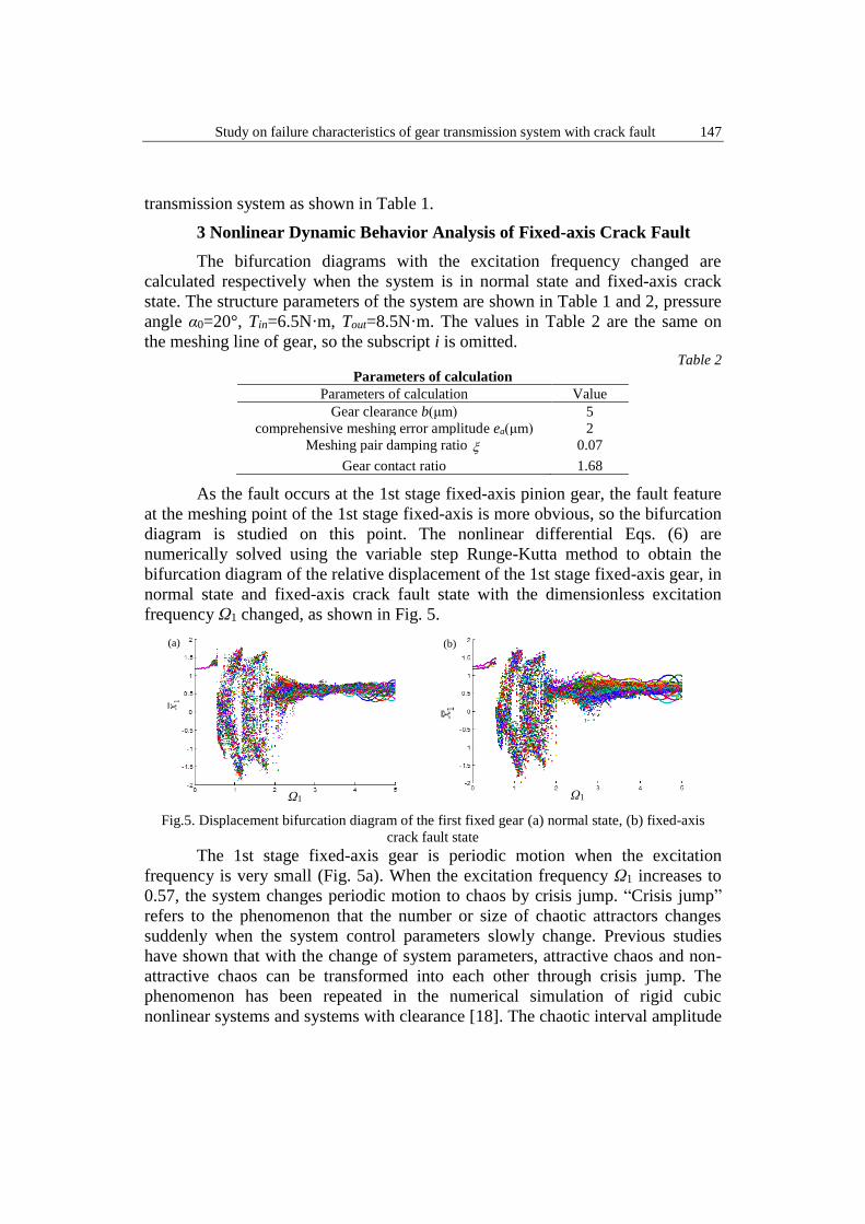
frequency Ω1 changed, as shown in Fig. 5.
Fig.5. Displacement bifurcation diagram of the first fixed gear (a) normal state, (b) fixed-axis
crack fault state
The 1st stage fixed-axis gear is periodic motion when the excitation
frequency is very small (Fig. 5a). When the excitation frequency Ω1 increases to
0.57, the system changes periodic motion to chaos by crisis jump. “Crisis jump”
refers to the phenomenon that the number or size of chaotic attractors changes
suddenly when the system control parameters slowly change. Previous studies
have shown that with the change of system parameters, attractive chaos and non-
attractive chaos can be transformed into each other through crisis jump. The
phenomenon has been repeated in the numerical simulation of rigid cubic
nonlinear systems and systems with clearance [18]. The chaotic interval amplitude
(a)
Ω1 Ω1
(b)
148 Xin Wang
decrease when the excitation frequency Ω1=1.9. It changes from chaos to quasi-
periodic motion when the excitation frequency Ω1=3.
Compared with Figs. 5a and b, the failure of the 1st stage fixed-axis crack
makes the single-periodic motion before the crisis at the meshing point of the 1st
stage fixed-axis gear becomes double periodic motion. The extra periodic is the
fault period. The newly added fault period can also be seen in the interval of the
excitation frequency [3,4], but can not be revealed in the chaotic interval.
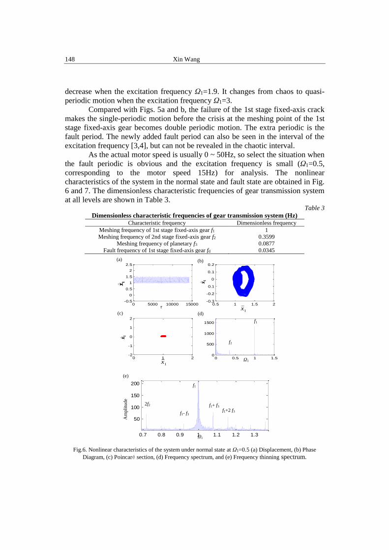
As the actual motor speed is usually 0 ~ 50Hz, so select the situation when
the fault periodic is obvious and the excitation frequency is small (Ω1=0.5,
corresponding to the motor speed 15Hz) for analysis. The nonlinear
characteristics of the system in the normal state and fault state are obtained in Fig.
6 and 7. The dimensionless characteristic frequencies of gear transmission system
at all levels are shown in Table 3. Table 3
Dimensionless characteristic frequencies of gear transmission system (Hz) Characteristic frequency Dimensionless frequency
Meshing frequency of 1st stage fixed-axis gear f1 1
Meshing frequency of 2nd stage fixed-axis gear f2 0.3599
Meshing frequency of planetary f3 0.0877
Fault frequency of 1st stage fixed-axis gear fd 0.0345
Fig.6. Nonlinear characteristics of the system under normal state at Ω1=0.5 (a) Displacement, (b) Phase
Diagram, (c) Poincaré section, (d) Frequency spectrum, and (e) Frequency thinning spectrum.
0 5000 10000 15000-0.5
0
0.5
1
1.5
2
2.5时域
t
x1
0.5 1 1.5 2-0.3
-0.2
-0.1
0
0.1
0.2相图
x1
dx1/
dt
0 1 2-2
-1
0
1
2Poincare
x1
dx1/
dt
0 0.5 1 1.50
500
1000
1500
频谱图
量纲一频率/Hz
幅值
0 5000 10000 15000-0.5
0
0.5
1
1.5
2
2.5时域
t
x1
0.5 1 1.5 2-0.3
-0.2
-0.1
0
0.1
0.2相图
x1
dx1/
dt
0 1 2-2
-1
0
1
2Poincare
x1
dx1/
dt
0 0.5 1 1.50
500
1000
1500
频谱图
量纲一频率/Hz
幅值
τ
1x
(a) (b)
1x
Ω1
(c) (d)
f1
f2
0 5000 10000 15000-0.5
0
0.5
1
1.5
2
2.5时域
t
x1
0.5 1 1.5 2-0.3
-0.2
-0.1
0
0.1
0.2相图
x1
dx1/
dt
0 1 2-2
-1
0
1
2Poincare
x1
dx1/
dt
0 0.5 1 1.50
500
1000
1500
频谱图
量纲一频率/Hz
幅值
0 5000 10000 15000-0.5
0
0.5
1
1.5
2
2.5Displacement
t
x1
0.9 1 1.1 1.2 1.3 1.4 1.5 1.6-0.3
-0.2
-0.1
0
0.1
0.2Phase Diagram
x1
dx1
/dt
0 0.5 1 1.5 2-2
-1
0
1
2Poincare
x1
dx1
/dt
0.7 0.8 0.9 1 1.1 1.2 1.3
50
100
150
200
频谱细化图
频率/Hz
幅值
f1
2f2 f1+ f3
f1- f3 f1+2 f3
Ω1
(e)
Am
pli
tude
Study on failure characteristics of gear transmission system with crack fault 149
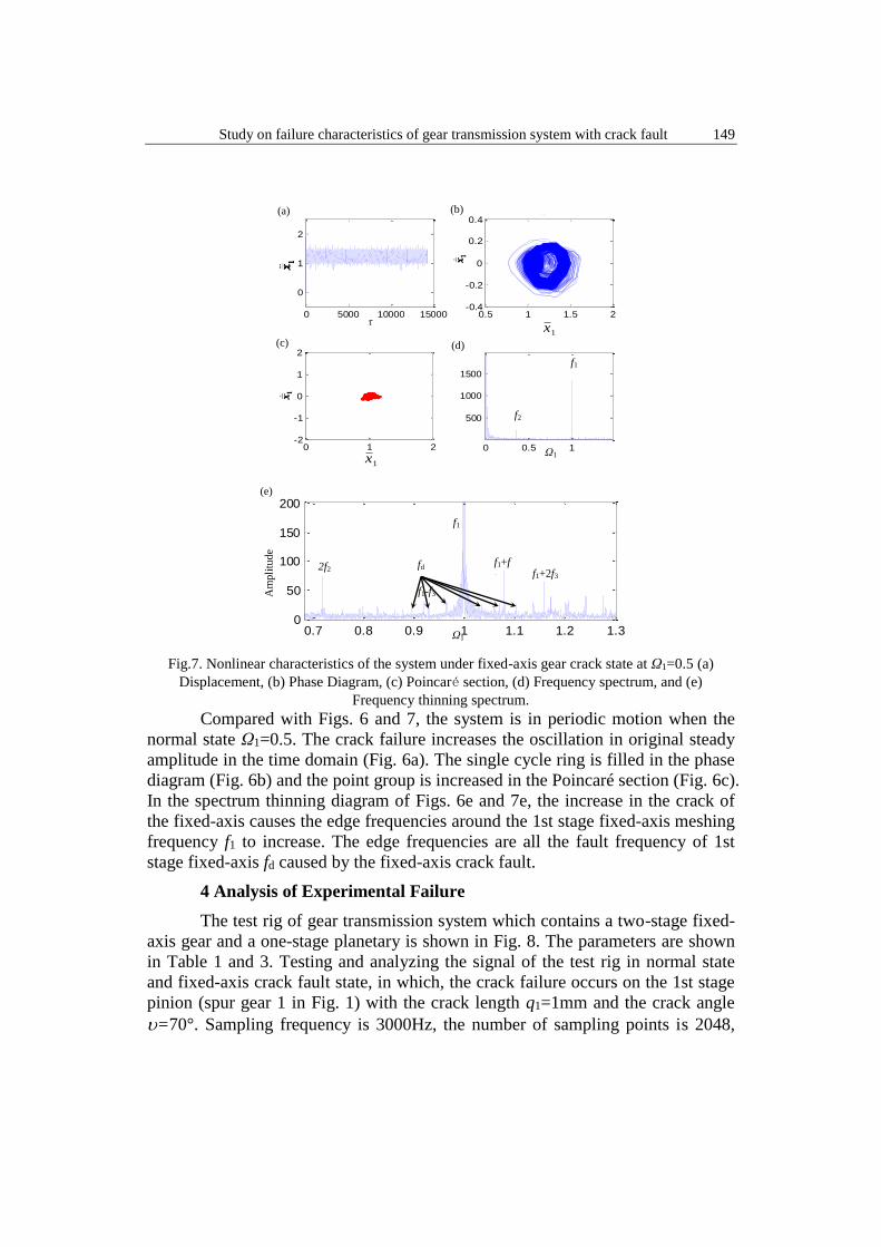
Fig.7. Nonlinear characteristics of the system under fixed-axis gear crack state at Ω1=0.5 (a)
Displacement, (b) Phase Diagram, (c) Poincaré section, (d) Frequency spectrum, and (e)
Frequency thinning spectrum.
Compared with Figs. 6 and 7, the system is in periodic motion when the
normal state Ω1=0.5. The crack failure increases the oscillation in original steady
amplitude in the time domain (Fig. 6a). The single cycle ring is filled in the phase
diagram (Fig. 6b) and the point group is increased in the Poincaré section (Fig. 6c).
In the spectrum thinning diagram of Figs. 6e and 7e, the increase in the crack of
the fixed-axis causes the edge frequencies around the 1st stage fixed-axis meshing
frequency f1 to increase. The edge frequencies are all the fault frequency of 1st
stage fixed-axis fd caused by the fixed-axis crack fault.
4 Analysis of Experimental Failure
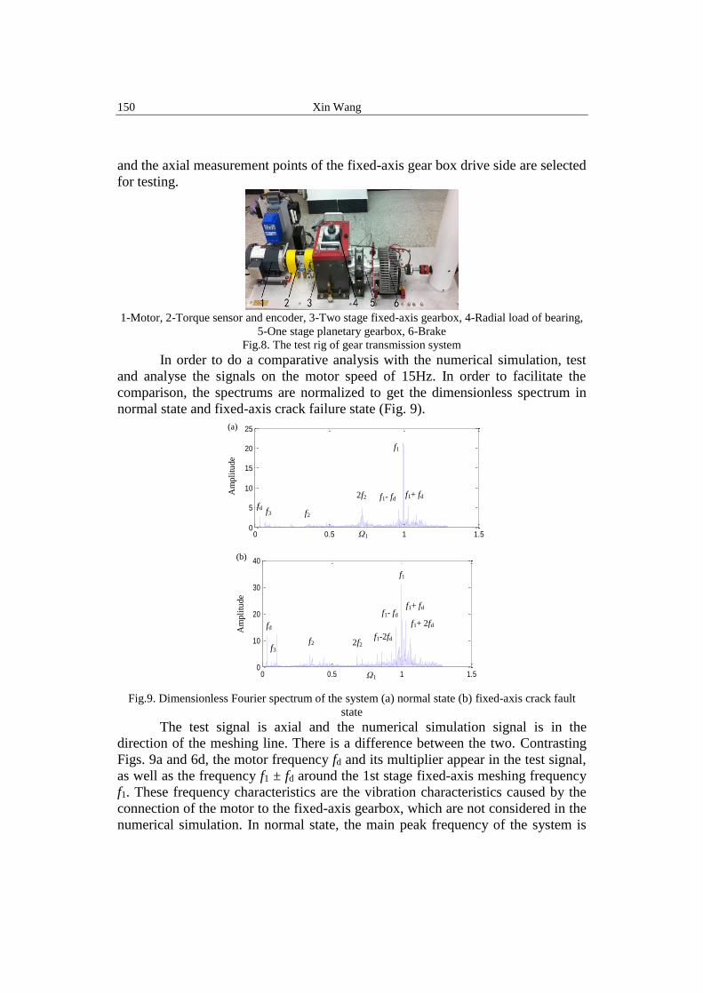
The test rig of gear transmission system which contains a two-stage fixed-
axis gear and a one-stage planetary is shown in Fig. 8. The parameters are shown
in Table 1 and 3. Testing and analyzing the signal of the test rig in normal state
and fixed-axis crack fault state, in which, the crack failure occurs on the 1st stage
pinion (spur gear 1 in Fig. 1) with the crack length q1=1mm and the crack angle
=70°. Sampling frequency is 3000Hz, the number of sampling points is 2048,
0 5000 10000 15000
0
1
2
时域
t
x1
0.5 1 1.5 2-0.4
-0.2
0
0.2
0.4相图
x1
dx1
/dt
0 1 2-2
-1
0
1
2Poincare
x1
dx1
/dt
0 0.5 1
500
1000
1500
频谱图
量纲一频率/Hz幅值
0 5000 10000 15000
0
1
2
时域
t
x1
0.5 1 1.5 2-0.4
-0.2
0
0.2
0.4相图
x1
dx1
/dt
0 1 2-2
-1
0
1
2Poincare
x1
dx1
/dt
0 0.5 1
500
1000
1500
频谱图
量纲一频率/Hz幅值
τ
1x
(a) (b)
1x
Ω1
(c) (d)
f1
f2
0 5000 10000 15000
0
1
2
时域
t
x1
0.5 1 1.5 2-0.4
-0.2
0
0.2
0.4相图
x1
dx1
/dt
0 1 2-2
-1
0
1
2Poincare
x1
dx1
/dt
0 0.5 1
500
1000
1500
频谱图
量纲一频率/Hz幅值
0 5000 10000 15000
0
1
2
Displacement
t
x1
0.8 1 1.2 1.4 1.6 1.8 2-0.4
-0.2
0
0.2
0.4Phase Diagram
x1
dx1
/dt
0 0.5 1 1.5 2-2
-1
0
1
2Poincare
x1
dx1
/dt
0.7 0.8 0.9 1 1.1 1.2 1.30
50
100
150
200
频谱细化图
频率/Hz
幅值
f1
fd
Ω1
(e)
Am
pli
tude
2f2 f1+f
3 f1+2f3
f1-f3
150 Xin Wang
and the axial measurement points of the fixed-axis gear box drive side are selected
for testing.
1-Motor, 2-Torque sensor and encoder, 3-Two stage fixed-axis gearbox, 4-Radial load of bearing,
5-One stage planetary gearbox, 6-Brake
Fig.8. The test rig of gear transmission system
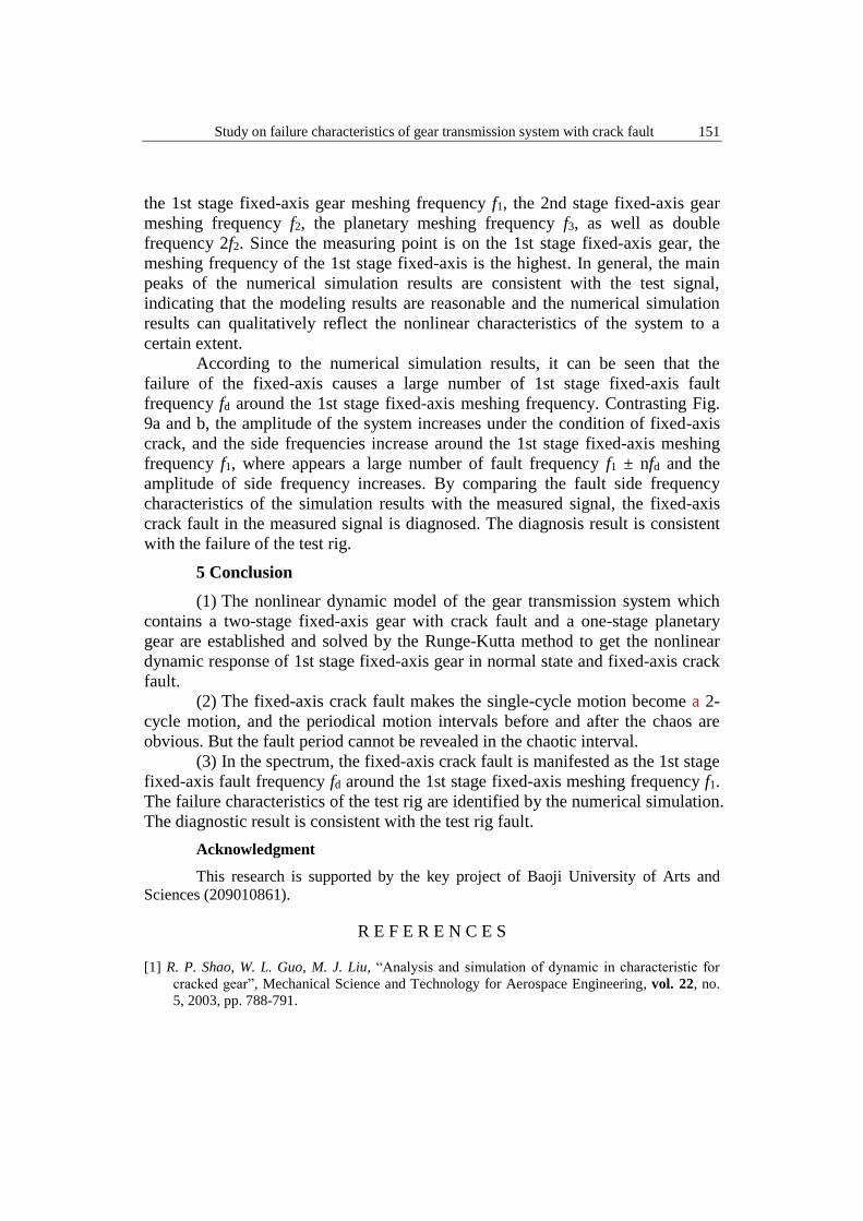
In order to do a comparative analysis with the numerical simulation, test
and analyse the signals on the motor speed of 15Hz. In order to facilitate the
comparison, the spectrums are normalized to get the dimensionless spectrum in
normal state and fixed-axis crack failure state (Fig. 9).
Fig.9. Dimensionless Fourier spectrum of the system (a) normal state (b) fixed-axis crack fault
state
The test signal is axial and the numerical simulation signal is in the
direction of the meshing line. There is a difference between the two. Contrasting
Figs. 9a and 6d, the motor frequency fd and its multiplier appear in the test signal,
as well as the frequency f1 ± fd around the 1st stage fixed-axis meshing frequency
f1. These frequency characteristics are the vibration characteristics caused by the
connection of the motor to the fixed-axis gearbox, which are not considered in the
numerical simulation. In normal state, the main peak frequency of the system is
0 0.5 1 1.50
5
10
15
20
25
频率/Hz
幅值
f1
2f2
f2 f3
f1+ fd f1- fd
Ω1
fd
(a)
Am
pli
tude
(b)
0 0.5 1 1.50
10
20
30
40
频率/Hz
幅值
f1
2f2 f2 f3
f1+ fd f1- fd
f1+ 2fd
f1-2fd
Ω1
fd Am
pli
tude
Study on failure characteristics of gear transmission system with crack fault 151
the 1st stage fixed-axis gear meshing frequency f1, the 2nd stage fixed-axis gear
meshing frequency f2, the planetary meshing frequency f3, as well as double
frequency 2f2. Since the measuring point is on the 1st stage fixed-axis gear, the
meshing frequency of the 1st stage fixed-axis is the highest. In general, the main
peaks of the numerical simulation results are consistent with the test signal,
indicating that the modeling results are reasonable and the numerical simulation
results can qualitatively reflect the nonlinear characteristics of the system to a
certain extent.
According to the numerical simulation results, it can be seen that the
failure of the fixed-axis causes a large number of 1st stage fixed-axis fault
frequency fd around the 1st stage fixed-axis meshing frequency. Contrasting Fig.
9a and b, the amplitude of the system increases under the condition of fixed-axis
crack, and the side frequencies increase around the 1st stage fixed-axis meshing
frequency f1, where appears a large number of fault frequency f1 ± nfd and the
amplitude of side frequency increases. By comparing the fault side frequency
characteristics of the simulation results with the measured signal, the fixed-axis
crack fault in the measured signal is diagnosed. The diagnosis result is consistent
with the failure of the test rig.
5 Conclusion
(1) The nonlinear dynamic model of the gear transmission system which
contains a two-stage fixed-axis gear with crack fault and a one-stage planetary
gear are established and solved by the Runge-Kutta method to get the nonlinear
dynamic response of 1st stage fixed-axis gear in normal state and fixed-axis crack
fault.
(2) The fixed-axis crack fault makes the single-cycle motion become a 2-
cycle motion, and the periodical motion intervals before and after the chaos are
obvious. But the fault period cannot be revealed in the chaotic interval.
(3) In the spectrum, the fixed-axis crack fault is manifested as the 1st stage
fixed-axis fault frequency fd around the 1st stage fixed-axis meshing frequency f1.
The failure characteristics of the test rig are identified by the numerical simulation.
The diagnostic result is consistent with the test rig fault.
Acknowledgment
This research is supported by the key project of Baoji University of Arts and
Sciences (209010861).
R E F E R E N C E S
[1] R. P. Shao, W. L. Guo, M. J. Liu, “Analysis and simulation of dynamic in characteristic for
cracked gear”, Mechanical Science and Technology for Aerospace Engineering, vol. 22, no.
5, 2003, pp. 788-791.
152 Xin Wang
[2] Y. C. Zhang, R. P. Shao, H. Y. Liu, “The influences of crack fault to dynamic characteristics in
gear transmission system”, Machinery Design&Manufacture, vol. 10, no. 10, 2006, pp. 12-
14.
[3] R. Ma, Y. S. Chen, “Nonlinear dynamic research on gear system with cracked failure”, Chinese
Journal of Mechanical Engineering, vol. 47, no. 21, 2011, pp. 84-90.
[4] R. Ma, Y. S. Chen, “Dynamic analysis of multi-freedom gear system with cracked failure”,
Journal of Daqing Petroleum Institute, vol. 36, no. 3, 2012, pp. 110-114.
[5] Q. F. Zhang, L. W. Tang, H. Q. Zheng, “Nonlinear dynamic fault model of gear transmission
system with gear tooth crack”, Journal of Vibration Engineering, vol. 24, no. 3, 2011, pp.
294-298.
[6] Y. G. Wang, H. Q. Zheng, T. Q. Yang, “Nonlinear dynamic behavior of gear system with fault
parameters”, Journal of Vibration, Measurement&Diagnosis, vol. 31, no. 5, 2011, pp. 570-
574.
[7] D. C. H. Yang, J. Y. Lin, “Hertzian damping, tooth friction and bending elasticity in gear
impact dynamics”, Journal of Mechanical Design, vol. 109, no. 2, 1987 ,pp. 189-196.
[8] X. H. Tian, “Dynamic simulation for system response of gearbox including localized gear
faults”, Master’s Thesis, University of Alberta, Edmonton, Alberta, Canada, 2004.
[9] Z. G. Chen, Z. F. Zhu, Y. M. Shao, “Fault feature analysis of planetary gear system with tooth
root crack and flexible ring gear rim”, Engineering Failure Analysis, 49, 2015, pp. 92-103.
[10] W. N. Yu, Y. M. Shao, C. K. Mechefske, “The effects of spur gear tooth spatial crack
propagation on gear mesh stiffness”, Engineering Failure Analysis, 54, 2015, pp. 103-119.
[11] Y. Pandya, A. Parey, “Experimental investigation of spur gear tooth mesh stiffness in the
presence of crack using photoelasticity technique”, Engineering Failure Analysis, 34, 2013,
pp. 488-500.
[12] X. H. Liang, M. J. Zuo, M. Pandey, “Analytically evaluating the influence of crack on the
mesh stiffness of a planetary gear set”, Mechanism and Machine Theory, vol. 76, 2014, pp.
20-38.
[13] A. Kapelevich, Y. Shekhtman, “Tooth fillet profile optimization for gears with symmetric and
asymmetric teeth”, Gear Technology, vol. 26, no. 7, 2009, pp. 73-79.
[14] X. Tian, M.J. Zuo, K. Fyfe, Analysis of the vibration response of a gearbox with gear tooth
faults, ASME International Mechanical Engineering Congress & Exposition, Anaheim,
California, USA, 2004, pp. 785-793.
[15] D. G. Lewicki, “Gear crack propagation path studies-guidelines for ultra-safe design”, ,Journal
of the American Helicopter Society, vol. 47, no. 1, 2002, pp. 64-72.
[16] A. Belsak, J. Flasker, “Detecting cracks in the tooth root of gears”, Engineering Failure
Analysis, 14, 2007, pp. 1466-1475.
[17] J. Kramberger, M. Šraml, S. Glodež, J. Flašker, I. Potrč, “Computational model for the
analysis of bending fatigue in gears", Computers & Structures, 82 (23–26), 2004, pp. 2261-
2269.
[18] E. Ott, “Chaos in Dynamic Systems”, Cambridge University Press, New York, 1993, pp. 277-
291.