Research into resistance to moisture in buildings ...
31
July 2019 PRP Architects LLP Ministry of Housing, Communities and Local Government Research into resistance to moisture in buildings Simplified rules
Transcript of Research into resistance to moisture in buildings ...

July 2019 PRP Architects LLP
Ministry of Housing, Communities and Local Government
Research into resistance to moisture in buildings Simplified rules

© Crown copyright, 2019 Copyright in the typographical arrangement rests with the Crown. You may re-use this information (not including logos) free of charge in any format or medium, under the terms of the Open Government Licence. To view this licence visit http://www.nationalarchives.gov.uk/doc/open-government-licence/version/3/
This document/publication is also available on our website at www.gov.uk/mhclg
If you have any enquiries regarding this document/publication, complete the form at http://forms.communities.gov.uk/ or write to us at:
Ministry of Housing, Communities and Local Government Fry Building 2 Marsham Street London SW1P 4DF Telephone: 030 3444 0000
For all our latest news and updates follow us on Twitter: https://twitter.com/mhclg
July 2019

3
The document is prepared by Innovate at PRP Limited, part of PRP Architects LLP.
Disclaimer: This report has been prepared for the above named client for the purpose agreed in PRP's terms of engagement. Whilst every effort has been made to ensure the accuracy and suitability of the information contained in this report, the results and recommendations presented should not be used as the basis of design, management or implementation of decisions unless the client has first discussed with PRP their suitability for these purposes and PRP has confirmed their suitability in writing to the client. PRP does not warrant, in any way whatsoever, the use of information contained in this report by parties other than the above named client.

4
Contents 1. Background ........................................................................................................... 5
2. Our Approach ....................................................................................................... 6
3. Categorisation of build-ups ................................................................................... 7
4. Conditions ........................................................................................................... 21
5. Notes .................................................................................................................. 28
6. Additional general findings .................................................................................. 31

5
1. Background It is a requirement of Part C of the Building Regulations that buildings, and people who use these buildings, are adequately protected from harmful effects of moisture. Approved Document C provides guidance on how to meet this requirement. However, much of this guidance was made before the energy performance requirements for buildings were improved in recent years and it is not certain that these recommendations are still appropriate. In addition, Approved Document C refers to a number of British Standards and other publications, but the usefulness and applicability of these documents, particularly in relation to retrofit works, required reviewing. It should be noted that this project focused specifically on moisture from precipitation, surface and interstitial condensation.
The Ministry of Housing, Communities and Local Government (MHCLG) commissioned PRP to carry out this research study, entitled Research into resistance to moisture in buildings.
The project was delivered in three main stages:
Stage One: Background research Stage One covered all the background research activities required to inform the refinement of the analysis methodology and the parameters used for the analysis.
Stage Two: Detailed analysis of identified construction typologies Stage Two involved the detailed analysis of the various construction types identified in Stage One for both new build and retrofit, including key thermal bridge junctions. In this stage, a number of software analysis packages and methodologies will be used to carry out a sensitivity analysis on each of the identified construction typologies:
Simplified Modelling based on BS EN ISO 13788 (2012) - the 'Glaser Method'
Standardised Modelling based on BS EN 15026 (2007) - with the use of a software package, WUFI (Wärme und Feuchte Instationär)
Multi-dimensional Thermal Modelling to BS EN ISO 10211 (2007) - with the use of THERM (for construction junctions only)
Stage Three: Simplified rules and recommendations
Stage Three involved the formulation of simplified rules and recommendations using the conclusions from the Stage Two work.
The outputs of this research are a series of eight reports, entitled:
• Research into resistance to moisture in buildings: Research Summary • Research into resistance to moisture in buildings: Identification of
common types of construction. • Research into resistance to moisture in buildings: Using calculation
methods to assess surface and interstitial condensation • Research into resistance to moisture in buildings: Using numerical
simulation to assess moisture risk in new constructions

6
• Research into resistance to moisture in buildings: Using numerical simulation to assess moisture risk in retrofit constructions. Part 1
• Research into resistance to moisture in buildings: Using numerical simulation to assess moisture risk in retrofit constructions. Part 2
• Research into resistance to moisture in buildings: Assessment of current moisture guidance
• Research into resistance to moisture in buildings: Simplified rules for reducing the risk of moisture
2. Our Approach This report is the Simplified rules for reducing the risk of moisture report of the Research into resistance to moisture in buildings project.
This report aims to achieve the following objective, based on the findings from the detailed analysis stage of this project:
To summarise the hygrothermal performance of the build-ups that were used in the detailed analysis (which have been developed based on what is commonly implemented in practice) and to categorise the build-ups according to their robustness against the risk of condensation and mould growth
Our approach in reporting is as follows
The build-ups are divided into four different categories and tabled in Section 3.
Some build-ups require additional conditions to be met in order that the build-up is reasonably robust against moisture risk. For these build-ups, a summary of the conditions is produced in Section 3.2.
Each condition is described more fully in Section 4. Additional findings and cautions on the build-ups can be found in Section 5
and 6.

7
3. Categorisation of build-ups 3.1. Summary table
Typology Category 1 Category 2 Category 3 Category 4
N1 - Suspended floor – insulated ●
R1.1 - Suspended floor – retrofit = insulation between joists insulation ●
R1.2 - Suspended floor – retrofit = insulation above joists insulation ●
N2 - Ground bearing concrete floor - insulated above ●
R2 - In-situ ground bearing concrete floors (uninsulated)Retrofit Measure: insulation above
●
N3 - Ground bearing concrete floor - insulated below ●
N4 - Concrete beam & block floor – insulated above concrete blocks ●
R4 - Concrete beam & block floor – retrofit = insulated above concrete blocks + screed ●

8
Typology Category 1 Category 2 Category 3 Category 4
N5 - Exposed suspended timber floor – insulated between AND below joists ●
R5.1 - Exposed suspended timber floor – retrofit = insulated between AND below joists ●
R5.2 - Exposed suspended timber floor – retrofit = insulated below joists ●
N6 - Exposed concrete floor – insulated above slab ●
R6 - Exposed concrete floor – retrofit = insulation above slab + screed ●
N7 - Exposed concrete floor – insulated below slab ●
R7 - Exposed concrete floor – retrofit = insulated below slab ●
N8 – solid concrete wall with IWI ●
Variation of R8 – solid brick wall with breathable IWI ●
Variation of R8 – solid brick wall with rigid IWI ●

9
Typology Category 1 Category 2 Category 3 Category 4
N9 - Solid concrete wall with external insulation ●
R9 - Solid brick wall with external insulation ●
N10 - Solid wall- external and internal insulation with a non-porous finish (Insulated concrete formwork) ●
N11 - Cavity wall – partial fill with a semi-porous finish ●
Variation of N11 – cavity wall (partial fill with rigid CWI) ●
R11.1 - Cavity masonry (uninsulated) – retrofit of IWI ●
R11.2 - Cavity masonry (uninsulated) – retrofit of External Wall Insulation + Cavity Wall Insulation ●
R11.3 - Cavity masonry (partial-fill) – retrofit of IWI ●
N12 - Cavity wall- full fill with a semi-porous finish ●
R12 – full-fill cavity masonry + retrofit of IWI ●

10
Typology Category 1 Category 2 Category 3 Category 4
N13 - Timber frame wall – with air gap and a semi-porous finish ●
N14 - Timber frame wall (with air gap and a non-porous finish) – with Frame insulation + EWI
●
R14.1 - Framed building (timber framed) Retrofit Measure: External Wall Insulation (EWI) ●
R14.2 - Framed building (timber framed) Retrofit Measure: Internal Wall Insulation (IWI) ●
N15 - Light Gauge Steel Frame (with air gap and a semi-porous finish) – with Frame insulation
●
N17 - Cold pitched roof (slates/concrete/clay tiles) ●
R17 - Cold pitched roof - insulated at ceiling level Retrofit Measure: Additional insulation above timber joists ●
N18 - Warm roof – slates / concrete / clay tiles ●
R18.1 - Warm pitched roof - uninsulated Retrofit Measure: Insulation below rafters ●
R18.2 - Warm pitched roof - uninsulated Retrofit Measure: Insulation between and below ●

11
Typology Category 1 Category 2 Category 3 Category 4
N19 - Warm flat roof - timber ●
R19 - Warm flat roof Retrofit Measure: insulation above ●
N20 - Cold roof – timber deck ●
R20 - Cold flat roof Retrofit Measure: insulation below ●
N21 - Warm roof - concrete ●
R21 - Warm flat concrete roof Retrofit Measure: insulation above ●
N22 - Inverted roof - concrete ●
R22 - Inverted flat concrete roof Retrofit Measure: insulation above ●

12
3.2. Category 1 The following table includes build-ups that are considered to be robust against moisture risk and therefore are of low risk of condensation and mould growth.
Typology Commentary N9 - Solid concrete wall with external insulation
R9 - Solid brick wall with external insulation
N10 - Solid wall- external and internal insulation with a non-porous finish (Insulated concrete formwork)
Insulation must be equally distributed on the inside and the outside, or more insulation on the outside.
R11.2 - Cavity masonry (uninsulated) – retrofit of External Wall Insulation + Cavity Wall Insulation
N22 - Inverted roof - concrete Insulation must be waterproof.
R22 - Inverted flat concrete roof Retrofit Measure: insulation above
Insulation must be waterproof.
13
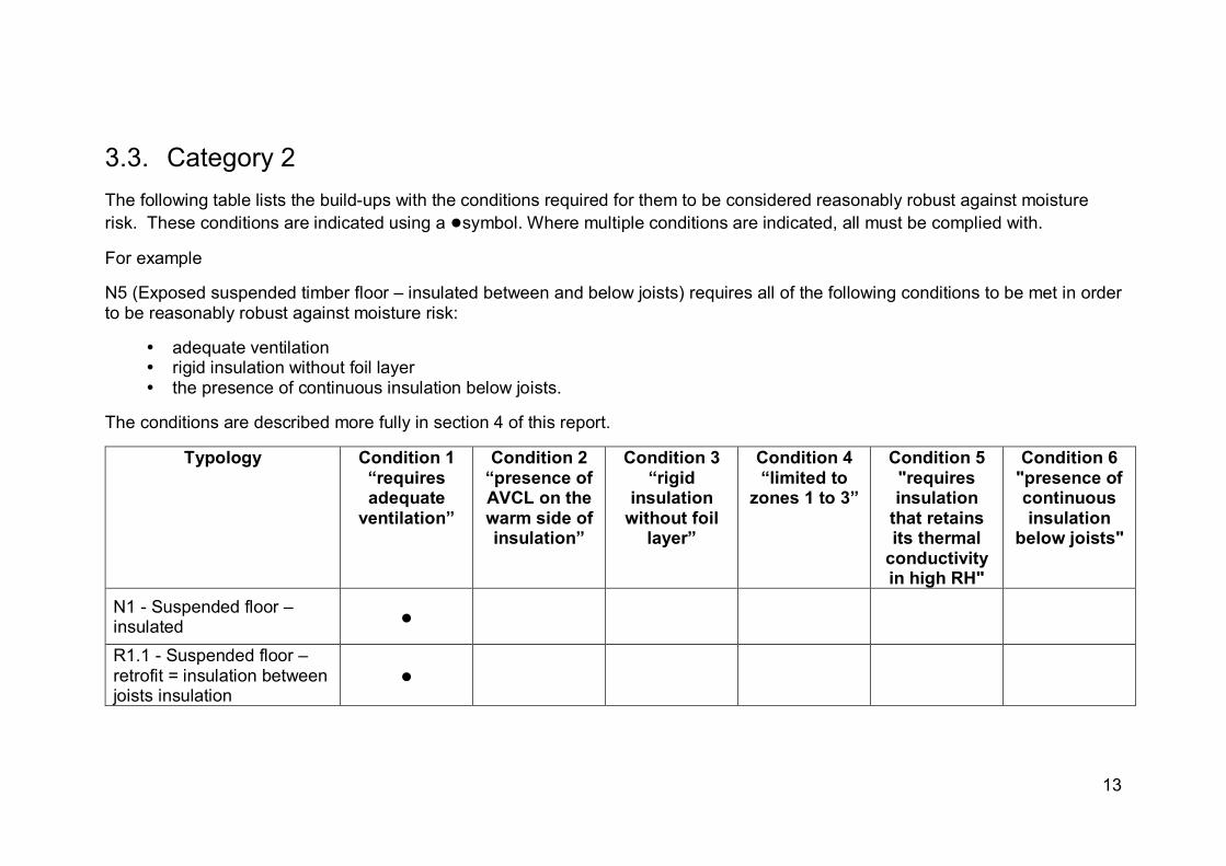
3.3. Category 2 The following table lists the build-ups with the conditions required for them to be considered reasonably robust against moisture risk. These conditions are indicated using a ●symbol. Where multiple conditions are indicated, all must be complied with.
For example
N5 (Exposed suspended timber floor – insulated between and below joists) requires all of the following conditions to be met in order to be reasonably robust against moisture risk:
adequate ventilation rigid insulation without foil layer the presence of continuous insulation below joists.
The conditions are described more fully in section 4 of this report.
Typology Condition 1 “requires adequate
ventilation”
Condition 2 “presence of AVCL on the warm side of insulation”
Condition 3 “rigid
insulation without foil
layer”
Condition 4 “limited to
zones 1 to 3”
Condition 5 "requires insulation
that retains its thermal
conductivity in high RH"
Condition 6 "presence of continuous insulation
below joists"
N1 - Suspended floor – insulated ●
R1.1 - Suspended floor – retrofit = insulation between joists insulation
●

14
Typology Condition 1 “requires adequate
ventilation”
Condition 2 “presence of AVCL on the warm side of insulation”
Condition 3 “rigid
insulation without foil
layer”
Condition 4 “limited to
zones 1 to 3”
Condition 5 "requires insulation
that retains its thermal
conductivity in high RH"
Condition 6 "presence of continuous insulation
below joists"
R1.2 - Suspended floor – retrofit = insulation above joists insulation
● ● ● ●
N4 - Concrete beam & block floor – insulated above concrete blocks
● ●
R4 - Concrete beam & block floor – retrofit = insulated above concrete blocks + screed
● ●
N5 - Exposed suspended timber floor – insulated between AND below joists
● ● ●
R5.1 - Exposed suspended timber floor – retrofit = insulated between AND below joists
● ● ●
R5.2 - Exposed suspended timber floor – retrofit = insulated below joists
●
N6 - Exposed concrete floor – insulated above slab ● ●

15
Typology Condition 1 “requires adequate
ventilation”
Condition 2 “presence of AVCL on the warm side of insulation”
Condition 3 “rigid
insulation without foil
layer”
Condition 4 “limited to
zones 1 to 3”
Condition 5 "requires insulation
that retains its thermal
conductivity in high RH"
Condition 6 "presence of continuous insulation
below joists"
R6 - Exposed concrete floor – retrofit = insulation above slab + screed
● ●
N7 - Exposed concrete floor – insulated below slab ●
R7 - Exposed concrete floor – retrofit = insulated below slab
●
N11 - Cavity wall – partial fill with a semi-porous finish ●
R11.1 - Cavity masonry (uninsulated) – retrofit of IWI
● ●
R11.3 - Cavity masonry (partial-fill) – retrofit of IWI ●
N17 - Cold pitched roof (slates/concrete/clay tiles) ●
R17 - Cold pitched roof - insulated at ceiling level Retrofit Measure: Additional insulation above timber joists
●

16
Typology Condition 1 “requires adequate
ventilation”
Condition 2 “presence of AVCL on the warm side of insulation”
Condition 3 “rigid
insulation without foil
layer”
Condition 4 “limited to
zones 1 to 3”
Condition 5 "requires insulation
that retains its thermal
conductivity in high RH"
Condition 6 "presence of continuous insulation
below joists"
N18 - Warm roof – slates / concrete / clay tiles ●
R18.2 - Warm pitched roof - uninsulated Retrofit Measure: Insulation between and below
●
N19 - Warm flat roof - timber
●
R19 - Warm flat roof Retrofit Measure: insulation above
● (Insulation must be dry at
installation)
N20 - Cold roof – timber deck ●
N21 - Warm roof - concrete
● (AVCL at least as moisture
resistant as roof
waterproofing)

17
Typology Condition 1 “requires adequate
ventilation”
Condition 2 “presence of AVCL on the warm side of insulation”
Condition 3 “rigid
insulation without foil
layer”
Condition 4 “limited to
zones 1 to 3”
Condition 5 "requires insulation
that retains its thermal
conductivity in high RH"
Condition 6 "presence of continuous insulation
below joists"
R21 - Warm flat concrete roof Retrofit Measure: insulation above
● (AVCL at least as moisture
resistant as roof
waterproofing)

18
3.4. Category 3 Examination of the following build-ups has exposed complicated matters that cannot be solved by the application of the conditions listed in Section 3.2. The final status of these build-ups may be changed with the addition of more complex conditions that are beyond the scope of the research project.
Typology Commentary N2 - Ground bearing concrete floor - insulated above
Glaser results suggested that the typology may not be robust enough against risk of interstitial condensation and this cannot be verified with WUFI modelling.
R2 - In-situ ground bearing concrete floors (uninsulated)Retrofit Measure: insulation above
Glaser results suggested that the typology may not be robust enough against risk of interstitial condensation and this cannot be verified with WUFI modelling.
N3 - Ground bearing concrete floor - insulated below
Glaser results suggested that the typology may not be robust enough against risk of interstitial condensation and this cannot be verified with WUFI modelling.
Variation of R8 – solid brick wall with breathable IWI Further research / modelling of breathable IWI systems
N13 - Timber frame wall – with air gap and a semi-porous finish
WUFI modelling revealed high RH level and water content at the junction with fragile material.
N14 - Timber frame wall (with air gap and a non-porous finish) – with Frame insulation + EWI
Conditions 1 and 2 apply to this typology; however, the typology would also require adequate levels of external insulation which varies between each exposure zones.

19
Typology Commentary R14.1 - Framed building (timber framed) Retrofit Measure: External Wall Insulation (EWI)
Conditions 1 and 2 apply to this typology; however, the typology would also require adequate levels of external insulation which varies between each exposure zones.
R14.2 - Framed building (timber framed) Retrofit Measure: Internal Wall Insulation (IWI)
WUFI modelling revealed high RH level and water content at the junction with fragile material.
N15 - Light Gauge Steel Frame (with air gap and a semi-porous finish) – with Frame insulation
Conditions 1 and 2 apply to this typology; however, the typology would also require adequate levels of external insulation which varies between each exposure zones.
20
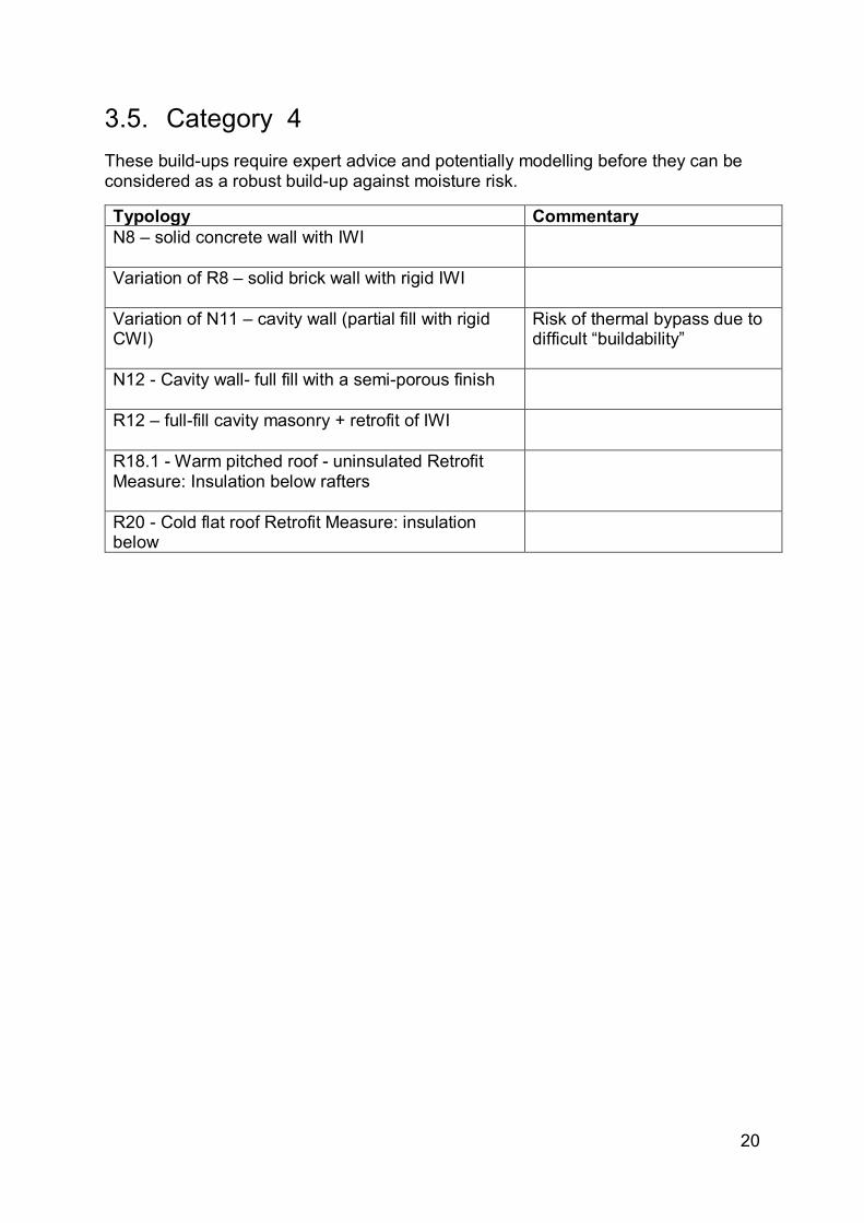
3.5. Category 4 These build-ups require expert advice and potentially modelling before they can be considered as a robust build-up against moisture risk.
Typology Commentary N8 – solid concrete wall with IWI
Variation of R8 – solid brick wall with rigid IWI
Variation of N11 – cavity wall (partial fill with rigid CWI)
Risk of thermal bypass due to difficult “buildability”
N12 - Cavity wall- full fill with a semi-porous finish
R12 – full-fill cavity masonry + retrofit of IWI
R18.1 - Warm pitched roof - uninsulated Retrofit Measure: Insulation below rafters
R20 - Cold flat roof Retrofit Measure: insulation below

21
4. Conditions 4.1. Condition 1 Ensure adequate ventilation within the cold side airspace in a construction type build-up
4.1.1. Explanation
The following build-ups have been identified by the Using numerical simulation to assess moisture risk in new constructions and / or Using numerical simulation to assess moisture risk in retrofit constructions analysis as low risk for surface and interstitial condensation / mould growth provided that the air layers present between the cold side of the structure and any weatherproofing are adequately ventilated.
The level of ventilation required will differ between build-ups, as follows (with the paragraphs highlighting the exact requirements in the guidance documents listed in brackets):
Suspended / exposed Timber Floors (see BS 5250 (2011), Para. F4.3) Suspended / exposed concrete floors (see BS 5250 (2011), Para. F4.2) Cavity Walls (see BS 5250 (2011), Para. G4.5.1 - This paragraph is
specifically for framed walls, but without explicit requirements for cavity walls, the requirements for frames walls might be extended to cavity walls)
Framed Walls (see BS 5250 (2011), Para. G4.5.1) Cold Pitched Roofs (see BS 5250 (2011), Para. H4.4) Warm Pitched Roofs (see BS 5250 (2011), Para. H5.3) Cold Flat Roofs (see BS 5250 (2011), Para. H7.1)
4.1.2. Typologies which this applies to
Floors
N1: Suspended floor – insulated R1.1: Suspended floor – retrofit = insulation between joists insulation R1.2: Suspended floor – retrofit = insulation above joists insulation N4: Concrete beam & block floor – insulated above concrete blocks R4: Concrete beam & block floor – retrofit = insulated above concrete
blocks + screed N5: Exposed suspended timber floor – insulated between AND below joists R5.1: Exposed suspended timber floor – retrofit = insulated between AND
below joists R5.2: Exposed suspended timber floor – retrofit = insulated below joists N6: Exposed concrete floor – insulated above slab R6: Exposed concrete floor – retrofit = insulation above slab + screed N7: Exposed concrete floor – insulated below slab R7: Exposed concrete floor – retrofit = insulated below slab

22
Walls
N11: Cavity wall – partial fill with a semi-porous finish R11.1: Cavity masonry (uninsulated) – retrofit of IWI R11.3: Cavity masonry (partial-fill) – retrofit of IWI N14: Timber frame wall (with air gap and a non-porous finish) – with Frame
insulation + EWI N15: Light Gauge Steel Frame (with air gap and a semi-porous finish) – with
Frame insulation + EWI
Roofs
N17: Cold pitched roof (slates/concrete/clay tiles) R17: Cold pitched roof - insulated at ceiling level: Retrofit Measure:
Additional insulation above timber joists N18: Warm roof – slates / concrete / clay tiles R18.2: Warm pitched roof - uninsulated: Retrofit Measure: Insulation
between and below R20 Cold flat roof: Retrofit Measure: Insulation below joists / Insulation
between and below joists

23
4.2. Condition 2 Build-up needs the presence of an AVCL on the warm side of the insulation
4.2.1. Explanation
The following build-ups have been identified by the Using numerical simulation to assess moisture risk in new constructions and / or Using numerical simulation to assess moisture risk in retrofit constructions analysis as low risk for surface and interstitial condensation / mould growth, provided that an AVCL is present on the warm side of the insulation.
Note: the need for an “exact” definition / characteristic (i.e. sd-value) of an AVCL (further research work needed).
Note: the characteristics of the AVCL might vary between different build-ups.
4.2.2. Typologies which this applies to
Floors
R1.2: Suspended floor – retrofit = insulation above joists insulation N6: Exposed concrete floor – insulated above slab
Walls
R11.1: Cavity masonry (uninsulated) – retrofit of IWI N14: Timber frame wall (with air gap and a non-porous finish) – with Frame
insulation + EWI R14.1 Framed building (timber framed) Retrofit Measure: External Wall
Insulation (EWI) N15: Light Gauge Steel Frame (with air gap and a semi-porous finish) – with
Frame insulation + EWI
Roofs
N17: Cold pitched roof (slates/concrete/clay tiles) R17: Cold pitched roof - insulated at ceiling level Retrofit Measure:
Additional insulation above timber joists N18: Warm roof – slates / concrete / clay tiles R18.2: Warm pitched roof - uninsulated: Retrofit Measure: Insulation
between and below R18.1 Warm pitched roof - uninsulated: Retrofit Measure: Insulation at rafter
level (below joists) N19 Warm flat roof - timber R19 - Warm flat roof Retrofit Measure: insulation above N21 Warm roof - concrete R21 Warm flat concrete roof Retrofit Measure: insulation above

24
4.3. Condition 3 Build-up needs the use of rigid insulation without foil layers (or any vapour retarder / barrier) present on the faces of the insulation
4.3.1. Explanation
The following build-ups have been identified by the Using numerical simulation to assess moisture risk in new constructions and / or Using numerical simulation to assess moisture risk in retrofit constructions analysis as low risk for surface and interstitial condensation / mould growth, provided that any rigid insulation installed is not of the type supplied with a foil vapour barrier. Installation of this type of insulation particularly on the external/cold side increases the likelihood of moisture becoming trapped within the structure.
4.3.2. Typologies which this applies to
Floors
R1.2: Suspended floor – retrofit = insulation above joists insulation N5 Exposed suspended timber floor – insulated between AND below joists R5.1 Exposed suspended timber floor – retrofit = insulated between AND
below joists

25
4.4. Condition 4 Build-up needs to be used / installed only in wind-driven rain exposure zones 1 to 3 (i.e. the build-up is entirely excluded from zone 4)
4.4.1. Explanation
The following build-ups have been identified by the Using numerical simulation to assess moisture risk in new constructions and / or Using numerical simulation to assess moisture risk in retrofit constructions analysis as low risk for surface and interstitial condensation / mould growth, provided the build-up is installed only in wind-driven rain exposure zones 1, 2 and 3.
4.4.2. Typologies which this applies to
Floors
R1.2: Suspended floor – retrofit = insulation above joists insulation
Walls
R11.1: Cavity masonry (uninsulated) – retrofit of IWI - This build-up may be useable in exposure zone 4 with a low level of insulation

26
4.5. Condition 5 Build-up needs insulation which retains its thermal conductivity in high RH conditions
4.5.1. Explanation
The following build-ups have been identified by the Using numerical simulation to assess moisture risk in new constructions and / or Using numerical simulation to assess moisture risk in retrofit constructions analysis as potentially having high RH levels over long periods of time in a layer of insulation, which although may not present a mould growth risk, could be detrimental to the performance of the insulation.
4.5.2. Typologies which this applies to
Floors
N4 Concrete beam & block floor – insulated above concrete blocks R4 Concrete beam & block floor – retrofit = insulated above concrete blocks
+ screed

27
4.6. Condition 6 Build-up needs the presence of continuous insulation below joists (with exact thickness / R-value requirements TBC).
4.6.1. Explanation
The following build-ups have been identified by the Using numerical simulation to assess moisture risk in new constructions and / or Using numerical simulation to assess moisture risk in retrofit constructions analysis as low risk for surface and interstitial condensation / mould growth, provided that insulation is present across the joists.
4.6.2. Typologies which this applies to
Floors
N5 Exposed suspended timber floor – insulated between AND below joists R5.1 Exposed suspended timber floor – retrofit = insulated between AND
below joists

28
5. Notes 5.1. Note 1
• Guidance documents (ADC and BS 5250) would benefit from being updated / being improved with additional details
• Build-up and build-up “sub divisions” would benefit from additional detail in documents (AD C / BS 5250)
5.1.1. Explanation
The following build-ups have been identified as having the potential to contain 'sub-divisions' in the insulation layers of their build-up. This typically occurs where the build-up contains structural cold bridging such as timber structural members or an insulating installation method involving framing where insulation (which can be of different types) is present both between and across these.
The single build-up format of AD C and BS 5250 results in at least one of the scenario's (presence or absence of additional un-bridged insulation layer) being undetailed in the current documentation.
5.1.2. Typologies which this applies to
Floors
N1: Suspended floor - insulated R1.1: Suspended timber floor (uninsulated) Retrofit Measure: insulation
between the joist N5: Exposed Suspended floor - insulated R5:.1 Exposed floors – suspended timber floor Retrofit Measure: insulation
between and below joists

29
Walls
N8: Solid concrete wall with internal insulation R8: Solid brick wall with internal insulation N11: Cavity wall – partial fill with a semi-porous finish R11.1: Cavity masonry (uninsulated) – retrofit of IWI R11.3: Cavity masonry (partial-fill) – retrofit of IWI R12: Cavity masonry (full-fill) – retrofit of IWI N13 Timber frame wall – with air gap and a semi-porous finish N14: Timber frame wall (with air gap and a non-porous finish) – with Frame
insulation + EWI R14.1 Framed building (timber framed) Retrofit Measure: External Wall
Insulation (EWI) R14.2 Framed building (timber framed) Retrofit Measure: Internal Wall
Insulation (IWI) N15: Light Gauge Steel Frame (with air gap and a semi-porous finish) – with
Frame insulation + EWI
Roofs
N17: Cold pitched roof (slates/concrete/clay tiles) R17: Cold pitched roof - insulated at ceiling level Retrofit Measure:
Additional insulation above timber joists N18: Warm roof – slates / concrete / clay tiles R18.1 Warm pitched roof - uninsulated Retrofit Measure: Insulation below
rafters R18.2: Warm pitched roof - uninsulated Retrofit Measure: Insulation
between and below N19 Warm flat roof - timber R19 Cold flat roof Retrofit Measure: insulation below R20 Warm flat timber roof Retrofit Measure: insulation above N21 Warm roof - concrete R21 Warm flat concrete roof Retrofit Measure: insulation above

30
5.2. Note 2 Current Part C U-value can be achieved with zero insulation
5.2.1. Explanation
The following build-ups have been identified by the Using numerical simulation to assess moisture risk in new constructions analysis as potentially meeting AD C U-value requirements in a build-up that contains no insulation.
5.2.2. Typologies which this applies to
Floors
N1 Suspended floor N3 Ground bearing concrete floor N4 Concrete beam & block floor
5.3. Note 3 Increasing levels of insulation increases moisture risk.
5.3.1. Explanation
The following build-ups have been identified by the Using numerical simulation to assess moisture risk in new constructions and / or Using numerical simulation to assess moisture risk in retrofit constructions analysis as build-ups where an increase in thermal insulation has the effect of increasing moisture risk - typically by decreasing temperatures within the structure by isolating them from the heat source (internal conditions).
5.3.2. Typologies which this applies to
Walls
N8 Solid concrete wall with internal insulation R8 Solid brick wall with internal insulation R11.1: Cavity masonry (uninsulated) – retrofit of IWI R11.3: Cavity masonry (partial-fill) – retrofit of IWI R12 Cavity masonry (full-fill) – retrofit of IWI
Roofs
N20 Cold roof – timber deck (negligible negative effect)

31
6. Additional general findings Floor airtightness and ABIS conditions have not been tested. It is anticipated that AVCL on the warm side of the insulation is beneficial to reduce moisture transfer via convection due to infiltration.
Best practice when retrofitting insulation is to install insulation when the substrate is as dry as possible.
There is a thermal bypass risk with non-compressible insulation, it should be considered good installation practice to ensure there are no gaps in the insulation.
External finishing layer characteristics need consideration since any permeable material will have an effect on hygrothermal performance.