Research Article Design and Investigation of Disk Patch...
7
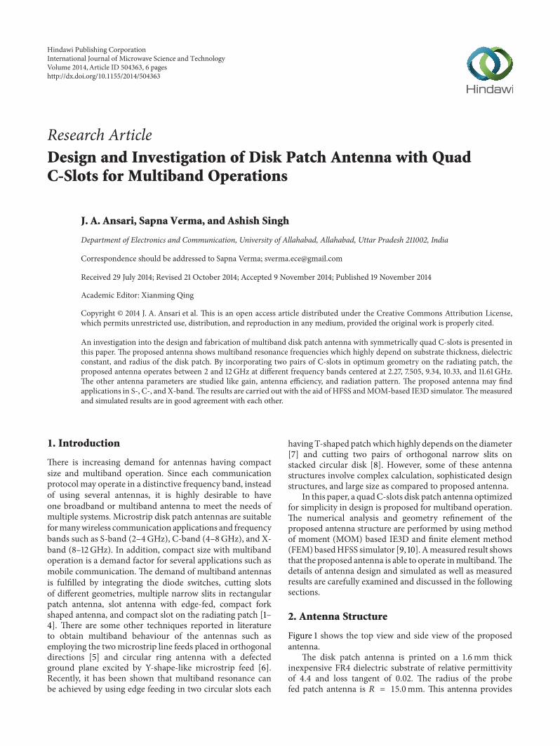
Research Article Design and Investigation of Disk Patch Antenna with Quad C-Slots for Multiband Operations J. A. Ansari, Sapna Verma, and Ashish Singh Department of Electronics and Communication, University of Allahabad, Allahabad, Uttar Pradesh 211002, India Correspondence should be addressed to Sapna Verma; [email protected] Received 29 July 2014; Revised 21 October 2014; Accepted 9 November 2014; Published 19 November 2014 Academic Editor: Xianming Qing Copyright © 2014 J. A. Ansari et al. is is an open access article distributed under the Creative Commons Attribution License, which permits unrestricted use, distribution, and reproduction in any medium, provided the original work is properly cited. An investigation into the design and fabrication of multiband disk patch antenna with symmetrically quad C-slots is presented in this paper. e proposed antenna shows multiband resonance frequencies which highly depend on substrate thickness, dielectric constant, and radius of the disk patch. By incorporating two pairs of C-slots in optimum geometry on the radiating patch, the proposed antenna operates between 2 and 12GHz at different frequency bands centered at 2.27, 7.505, 9.34, 10.33, and 11.61GHz. e other antenna parameters are studied like gain, antenna efficiency, and radiation pattern. e proposed antenna may find applications in S-, C-, and X-band. e results are carried out with the aid of HFSS and MOM-based IE3D simulator. e measured and simulated results are in good agreement with each other. 1. Introduction ere is increasing demand for antennas having compact size and multiband operation. Since each communication protocol may operate in a distinctive frequency band, instead of using several antennas, it is highly desirable to have one broadband or multiband antenna to meet the needs of multiple systems. Microstrip disk patch antennas are suitable for many wireless communication applications and frequency bands such as S-band (2–4 GHz), C-band (4–8 GHz), and X- band (8–12 GHz). In addition, compact size with multiband operation is a demand factor for several applications such as mobile communication. e demand of multiband antennas is fulfilled by integrating the diode switches, cutting slots of different geometries, multiple narrow slits in rectangular patch antenna, slot antenna with edge-fed, compact fork shaped antenna, and compact slot on the radiating patch [1– 4]. ere are some other techniques reported in literature to obtain multiband behaviour of the antennas such as employing the two microstrip line feeds placed in orthogonal directions [5] and circular ring antenna with a defected ground plane excited by Y-shape-like microstrip feed [6]. Recently, it has been shown that multiband resonance can be achieved by using edge feeding in two circular slots each having T-shaped patch which highly depends on the diameter [7] and cutting two pairs of orthogonal narrow slits on stacked circular disk [8]. However, some of these antenna structures involve complex calculation, sophisticated design structures, and large size as compared to proposed antenna. In this paper, a quad C-slots disk patch antenna optimized for simplicity in design is proposed for multiband operation. e numerical analysis and geometry refinement of the proposed antenna structure are performed by using method of moment (MOM) based IE3D and finite element method (FEM) based HFSS simulator [9, 10]. A measured result shows that the proposed antenna is able to operate in multiband. e details of antenna design and simulated as well as measured results are carefully examined and discussed in the following sections. 2. Antenna Structure Figure 1 shows the top view and side view of the proposed antenna. e disk patch antenna is printed on a 1.6 mm thick inexpensive FR4 dielectric substrate of relative permittivity of 4.4 and loss tangent of 0.02. e radius of the probe fed patch antenna is = 15.0 mm. is antenna provides Hindawi Publishing Corporation International Journal of Microwave Science and Technology Volume 2014, Article ID 504363, 6 pages http://dx.doi.org/10.1155/2014/504363
-
Upload
phungkhuong -
Category
Documents
-
view
220 -
download
0
Transcript of Research Article Design and Investigation of Disk Patch...
Research ArticleDesign and Investigation of Disk Patch Antenna with QuadC-Slots for Multiband Operations
J. A. Ansari, Sapna Verma, and Ashish Singh
Department of Electronics and Communication, University of Allahabad, Allahabad, Uttar Pradesh 211002, India
Correspondence should be addressed to Sapna Verma; [email protected]
Received 29 July 2014; Revised 21 October 2014; Accepted 9 November 2014; Published 19 November 2014
Academic Editor: Xianming Qing
Copyright © 2014 J. A. Ansari et al. This is an open access article distributed under the Creative Commons Attribution License,which permits unrestricted use, distribution, and reproduction in any medium, provided the original work is properly cited.
An investigation into the design and fabrication of multiband disk patch antenna with symmetrically quad C-slots is presented inthis paper. The proposed antenna shows multiband resonance frequencies which highly depend on substrate thickness, dielectricconstant, and radius of the disk patch. By incorporating two pairs of C-slots in optimum geometry on the radiating patch, theproposed antenna operates between 2 and 12GHz at different frequency bands centered at 2.27, 7.505, 9.34, 10.33, and 11.61 GHz.The other antenna parameters are studied like gain, antenna efficiency, and radiation pattern. The proposed antenna may findapplications in S-, C-, and X-band.The results are carried out with the aid of HFSS andMOM-based IE3D simulator.Themeasuredand simulated results are in good agreement with each other.
1. Introduction
There is increasing demand for antennas having compactsize and multiband operation. Since each communicationprotocol may operate in a distinctive frequency band, insteadof using several antennas, it is highly desirable to haveone broadband or multiband antenna to meet the needs ofmultiple systems. Microstrip disk patch antennas are suitableformanywireless communication applications and frequencybands such as S-band (2–4GHz), C-band (4–8GHz), and X-band (8–12GHz). In addition, compact size with multibandoperation is a demand factor for several applications such asmobile communication. The demand of multiband antennasis fulfilled by integrating the diode switches, cutting slotsof different geometries, multiple narrow slits in rectangularpatch antenna, slot antenna with edge-fed, compact forkshaped antenna, and compact slot on the radiating patch [1–4]. There are some other techniques reported in literatureto obtain multiband behaviour of the antennas such asemploying the twomicrostrip line feeds placed in orthogonaldirections [5] and circular ring antenna with a defectedground plane excited by Y-shape-like microstrip feed [6].Recently, it has been shown that multiband resonance canbe achieved by using edge feeding in two circular slots each
having T-shaped patchwhich highly depends on the diameter[7] and cutting two pairs of orthogonal narrow slits onstacked circular disk [8]. However, some of these antennastructures involve complex calculation, sophisticated designstructures, and large size as compared to proposed antenna.
In this paper, a quadC-slots disk patch antenna optimizedfor simplicity in design is proposed for multiband operation.The numerical analysis and geometry refinement of theproposed antenna structure are performed by using methodof moment (MOM) based IE3D and finite element method(FEM)basedHFSS simulator [9, 10]. Ameasured result showsthat the proposed antenna is able to operate inmultiband.Thedetails of antenna design and simulated as well as measuredresults are carefully examined and discussed in the followingsections.
2. Antenna Structure
Figure 1 shows the top view and side view of the proposedantenna.
The disk patch antenna is printed on a 1.6mm thickinexpensive FR4 dielectric substrate of relative permittivityof 4.4 and loss tangent of 0.02. The radius of the probefed patch antenna is 𝑅 = 15.0mm. This antenna provides
Hindawi Publishing CorporationInternational Journal of Microwave Science and TechnologyVolume 2014, Article ID 504363, 6 pageshttp://dx.doi.org/10.1155/2014/504363

2 International Journal of Microwave Science and Technology
Y
X
Feed positionW
L1
L2
L4 L5
L3
(a)
FR4
Patch
SMA connectorGND
h
(b)
Figure 1: Geometry of the disk patch antenna with quad symmet-rical C-slots. (a) Top view of the proposed antenna. (b) Side view ofthe proposed antenna.
the multiband operation due to the quad symmetrical C-slots etched on the edge of the radiating patch. The optimalparameters of the C- and inverted C-slots are kept equal. The𝐿1= 11.0mm, 𝐿
4= 𝐿5= 5.0mm, and 𝐿
2= 𝐿3= 2.0mm
are horizontal and vertical slots of the proposed antenna,respectively. The𝑊 = 0.5mm is the width of the horizontaland vertical slots of C- and inverted C-slots.
Theoretically the effect of embeddedC-slots on disk patchcan be approximately obtained by the impedance of a shortdipole via well-known Babinet’s principle [11, 12] given as
𝑍slot ⋅ 𝑍dipole =𝜂2
0
4,
𝑍dipole
≈ 𝑓1(𝛽𝑙) − 𝑗 (120 (ln 2𝐿
𝑊− 1) cot (𝛽𝑙) − 𝑓
2(𝛽𝑙)) ,
𝑓1(𝛽𝑙)
= −0.4787 + 7.3246 (𝛽𝑙) + 0.3963 (𝛽𝑙)2
+ 15.613 (𝛽𝑙)3
,
𝑓2(𝛽𝑙)
= −0.4456 + 17.0082 (𝛽𝑙) − 8.6793 (𝛽𝑙)2
+ 9.6031 (𝛽𝑙)3
,
(1)
Figure 2: Fabricated photo of the proposed antenna.
1 3 5 7 9 11 13
0
Frequency (GHz)
ExperimentalIE3DHFSS
−5
−10
−15
−20
−25
−30
S 11
(dB)
Figure 3: Simulated and measured S11of proposed antenna.
where 𝜂0= 120𝜋, L = length of the dipole, andW = width or
diameter of the dipole.
3. Results and Discussion
A photograph of the fabricated quad C-slots loaded diskpatch antenna is shown in Figure 2. The Agilent E5071CNetwork Analyzer is used to measure the measured S
11
of the proposed antenna and the simulation performed byIE3D and HFSS simulator. The measured and simulated S
11
parameters of the proposed antenna are compared as shownin Figure 3, which exhibit good agreement and meet the−10 dB requirement in most resonance frequencies that are2.27, 7.505, 9.34, 10.33, and 11.61 GHz. An important featureof the proposed antenna is capable of impedance matching atfive resonance frequencies by cutting one by one quad C-slotswithout changing the feeding point and any other dimensionson the disk patch antenna.
It is observed that the proposed antenna has multifre-quency characteristics. This happens due to the slots insertedon the radiating patch. In the first case, first C-slot is cut on
International Journal of Microwave Science and Technology 3
the radiating patch which gives two resonating frequencies.In the second case, second C-slot loaded to the patch whichproduces third resonating frequency. Thereafter in the nexttwo steps, three and four C-slots are inserted and the four andfive resonance frequency bandswere observed.Thus, the slotsplay vital role in obtaining multiband.
The multiband nature of the proposed structure is foundto be confirmed by the fabricated results with some errorswithin the acceptable limits.
Apparently, the measured return loss below −10 dB band-widths ranges from 2.17 to 2.41 GHz, 7.38 to 7.64GHz, 9.21to 9.485GHz, 10.19 to 10.45GHz, and 11.46 to 11.75GHz withthe relative bandwidth of 10.45%, 3.46%, 2.94%, 2.51%, and2.498%, respectively, which show the approximate agreementwith the simulated results. The differences may be due to theeffect of the SMA connector and mismatching tolerance.
The first resonance frequency band operates under theS-band, second resonance frequency band operates at C-band, and third, fourth, and fifth resonance frequency bandsoperate at X-band.
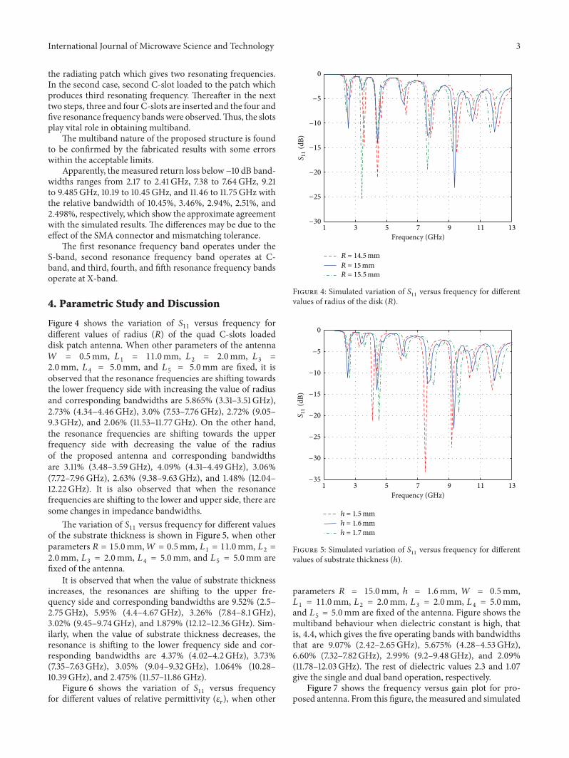
4. Parametric Study and Discussion
Figure 4 shows the variation of S11
versus frequency fordifferent values of radius (𝑅) of the quad C-slots loadeddisk patch antenna. When other parameters of the antenna𝑊 = 0.5mm, 𝐿
1= 11.0mm, 𝐿
2= 2.0mm, 𝐿
3=
2.0mm, 𝐿4= 5.0mm, and 𝐿
5= 5.0mm are fixed, it is
observed that the resonance frequencies are shifting towardsthe lower frequency side with increasing the value of radiusand corresponding bandwidths are 5.865% (3.31–3.51 GHz),2.73% (4.34–4.46GHz), 3.0% (7.53–7.76GHz), 2.72% (9.05–9.3GHz), and 2.06% (11.53–11.77GHz). On the other hand,the resonance frequencies are shifting towards the upperfrequency side with decreasing the value of the radiusof the proposed antenna and corresponding bandwidthsare 3.11% (3.48–3.59GHz), 4.09% (4.31–4.49GHz), 3.06%(7.72–7.96GHz), 2.63% (9.38–9.63GHz), and 1.48% (12.04–12.22GHz). It is also observed that when the resonancefrequencies are shifting to the lower and upper side, there aresome changes in impedance bandwidths.
The variation of S11versus frequency for different values
of the substrate thickness is shown in Figure 5, when otherparameters 𝑅 = 15.0mm,𝑊 = 0.5mm, 𝐿
1= 11.0mm, 𝐿
2=
2.0mm, 𝐿3= 2.0mm, 𝐿
4= 5.0mm, and 𝐿
5= 5.0mm are
fixed of the antenna.It is observed that when the value of substrate thickness
increases, the resonances are shifting to the upper fre-quency side and corresponding bandwidths are 9.52% (2.5–2.75GHz), 5.95% (4.4–4.67GHz), 3.26% (7.84–8.1 GHz),3.02% (9.45–9.74GHz), and 1.879% (12.12–12.36GHz). Sim-ilarly, when the value of substrate thickness decreases, theresonance is shifting to the lower frequency side and cor-responding bandwidths are 4.37% (4.02–4.2GHz), 3.73%(7.35–7.63GHz), 3.05% (9.04–9.32GHz), 1.064% (10.28–10.39GHz), and 2.475% (11.57–11.86GHz).
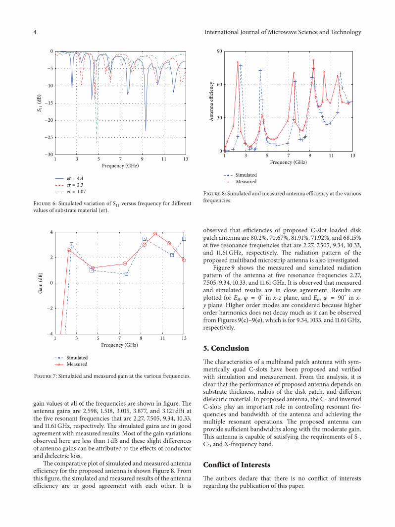
Figure 6 shows the variation of S11
versus frequencyfor different values of relative permittivity (𝜀
𝑟), when other
1 3 5 7 9 11 13
0
Frequency (GHz)
−5
−10
−15
−20
−25
−30
S 11
(dB)
R = 14.5mmR = 15mmR = 15.5mm
Figure 4: Simulated variation of S11versus frequency for different
values of radius of the disk (𝑅).
1 3 5 7 9 11 13
0
Frequency (GHz)
−5
−10
−15
−20
−25
−30
−35
S 11
(dB)
h = 1.5mmh = 1.6mmh = 1.7mm
Figure 5: Simulated variation of S11versus frequency for different
values of substrate thickness (ℎ).
parameters 𝑅 = 15.0mm, ℎ = 1.6mm, 𝑊 = 0.5mm,𝐿1= 11.0mm, 𝐿
2= 2.0mm, 𝐿
3= 2.0mm, 𝐿
4= 5.0mm,
and 𝐿5= 5.0mm are fixed of the antenna. Figure shows the
multiband behaviour when dielectric constant is high, thatis, 4.4, which gives the five operating bands with bandwidthsthat are 9.07% (2.42–2.65GHz), 5.675% (4.28–4.53GHz),6.60% (7.32–7.82GHz), 2.99% (9.2–9.48GHz), and 2.09%(11.78–12.03GHz). The rest of dielectric values 2.3 and 1.07give the single and dual band operation, respectively.
Figure 7 shows the frequency versus gain plot for pro-posed antenna. From this figure, the measured and simulated
4 International Journal of Microwave Science and Technology
1 3 5 7 9 11 13
0
Frequency (GHz)
−5
−10
−15
−20
−25
−30
S 11
(dB)
er = 4.4
er = 2.3
er = 1.07
Figure 6: Simulated variation of S11versus frequency for different
values of substrate material (er).
1 3 5 7 9 11 13
0
2
4
Frequency (GHz)
Gai
n (d
B)
SimulatedMeasured
−4
−2
Figure 7: Simulated and measured gain at the various frequencies.
gain values at all of the frequencies are shown in figure. Theantenna gains are 2.598, 1.518, 3.015, 3.877, and 3.121 dBi atthe five resonant frequencies that are 2.27, 7.505, 9.34, 10.33,and 11.61 GHz, respectively. The simulated gains are in goodagreement with measured results. Most of the gain variationsobserved here are less than 1 dB and these slight differencesof antenna gains can be attributed to the effects of conductorand dielectric loss.
The comparative plot of simulated andmeasured antennaefficiency for the proposed antenna is shown Figure 8. Fromthis figure, the simulated andmeasured results of the antennaefficiency are in good agreement with each other. It is
1 3 5 7 9 11 130
30
60
90
Frequency (GHz)
Ant
enna
effici
ency
SimulatedMeasured
Figure 8: Simulated andmeasured antenna efficiency at the variousfrequencies.
observed that efficiencies of proposed C-slot loaded diskpatch antenna are 80.2%, 70.67%, 81.91%, 71.92%, and 68.15%at five resonance frequencies that are 2.27, 7.505, 9.34, 10.33,and 11.61 GHz, respectively. The radiation pattern of theproposed multiband microstrip antenna is also investigated.
Figure 9 shows the measured and simulated radiationpattern of the antenna at five resonance frequencies 2.27,7.505, 9.34, 10.33, and 11.61 GHz. It is observed that measuredand simulated results are in close agreement. Results areplotted for 𝐸
𝜃, 𝜑 = 0
∘ in x-z plane, and 𝐸𝜃, 𝜑 = 90
∘ in x-y plane. Higher order modes are considered because higherorder harmonics does not decay much as it can be observedfrom Figures 9(c)–9(e), which is for 9.34, 1033, and 11.61 GHz,respectively.
5. Conclusion
The characteristics of a multiband patch antenna with sym-metrically quad C-slots have been proposed and verifiedwith simulation and measurement. From the analysis, it isclear that the performance of proposed antenna depends onsubstrate thickness, radius of the disk patch, and differentdielectric material. In proposed antenna, the C- and invertedC-slots play an important role in controlling resonant fre-quencies and bandwidth of the antenna and achieving themultiple resonant operations. The proposed antenna canprovide sufficient bandwidths along with the moderate gain.This antenna is capable of satisfying the requirements of S-,C-, and X-frequency band.
Conflict of Interests
The authors declare that there is no conflict of interestsregarding the publication of this paper.

International Journal of Microwave Science and Technology 5
30
210
60
240
270
120
300
150
330
180
0
(dB)
0
−20
−15
−10 −5
Simulated (E𝜃 , 𝜑 = 0deg)Simulated (E𝜃 , 𝜑 = 90deg)Measured (E𝜃 , 𝜑 = 0deg)Measured (E𝜃 , 𝜑 = 90deg)
90deg
(a) 2.27GHz
30
210
60
240
270
120
300
150
330
180
0
0
−25
−20
(dB)
−15
−10 −5
Simulated (E𝜃 , 𝜑 = 0deg)Simulated (E𝜃 , 𝜑 = 90deg)Measured (E𝜃 , 𝜑 = 0deg)Measured (E𝜃 , 𝜑 = 90deg)
90deg
(b) 7.505GHz
30
210
60
240
270
120
150
330
180
0
300
0
(dB)
−20
−15
−10 −5
Simulated (E𝜃 , 𝜑 = 0deg)Simulated (E𝜃 , 𝜑 = 90deg)Measured (E𝜃 , 𝜑 = 0deg)Measured (E𝜃 , 𝜑 = 90deg)
90deg
(c) 9.34GHz
30
210
60
240
270
120
300
150
330
180
0
(dB)
0
−20
−10
Simulated (E𝜃 , 𝜑 = 0deg)Simulated (E𝜃 , 𝜑 = 90deg)Measured (E𝜃 , 𝜑 = 0deg)Measured (E𝜃 , 𝜑 = 90deg)
−40
−30
90deg
(d) 10.33GHz
30
210
60
240
270
120
300
150
330
180
0
0
Simulated (E𝜃 , 𝜑 = 0deg)Simulated (E𝜃 , 𝜑 = 90deg)Measured (E𝜃 , 𝜑 = 0deg)Measured (E𝜃 , 𝜑 = 90deg)
(dB)
−20
−10
−40
−30
90deg
(e) 11.61 GHz
Figure 9: Simulated and measured radiation pattern at the various frequencies.
6 International Journal of Microwave Science and Technology
Acknowledgment
SapnaVerma is also grateful toUniversity Grant Commission(UGC), India, for providing financial assistance (SRF).
References
[1] D. N. Elsheakh, H. A. Elsadek, E. A. Abdallah, M. F. Iskander,and H. Elhenawi, “Reconfigurable single and multiband insetfeed microstrip patch antenna for wireless communicationdevices,”Progress in Electromagnetics ResearchC, vol. 12, pp. 191–201, 2010.
[2] S. Verma, J. A. Ansari, and M. K. Verma, “A novel compactmulti-band microstrip antenna with multiple narrow slits,”Microwave and Optical Technology Letters, vol. 55, no. 6, pp.1196–1198, 2013.
[3] L. Xu, Z. Y. Xin, and J. He, “A compact triple-band fork-shaped antenna for WLAN/WiMAX applications,” Progress inElectromagnetics Research Letters, vol. 40, pp. 61–69, 2013.
[4] L. Dang, Z. Y. Lei, Y. J. Xie, G. L. Ning, and J. Fan, “A compactmicrostrip slot triple-band antenna for WLAN/WiMAX appli-cations,” IEEE Antennas andWireless Propagation Letters, vol. 9,pp. 1178–1181, 2010.
[5] J. P. Thakur, J.-S. Park, B.-J. Jang, and H.-G. Cho, “Smallsize quad band microstrip antenna,” Microwave and OpticalTechnology Letters, vol. 49, no. 5, pp. 997–1001, 2007.
[6] J. Pei, A.-G. Wang, S. Gao, and W. Leng, “Miniaturized triple-band antenna with a defected ground plane for WLAN/WiMAX applications,” IEEE Antennas andWireless PropagationLetters, vol. 10, pp. 298–301, 2011.
[7] X. Sun, G. Zeng, H.-C. Yang, Y. Li, X.-J. Liao, and L. Wang,“Design of an edge-fed quad-band slot antenna for GPS/WIMAX/WLAN applications,” Progress in ElectromagneticsResearch Letters, vol. 28, pp. 111–120, 2012.
[8] S. K. Gupta, A. Sharma, B. K. Kanaujia, S. Rudra, R. R. Mishra,and G. P. Pandey, “Orthogonal slit cut stacked circular patchmicrostrip antenna for multiband operations,” Microwave andOptical Technology Letters, vol. 55, no. 4, pp. 873–882, 2013.
[9] Zeland Software, IE3D Simulation Software, Version 14.05,Zeland Software, 2008.
[10] “HFSS simulator version 12,” Ansoft Corporation, Pittsburg, Pa,USA.
[11] Y. I. Huang and K. Boyle,Antenna fromTheory to Practice, JohnWiley & Sons, 2008.
[12] M. Kominami, D. M. Pozar, and D. H. Schaubert, “Dipoleand slot elements and array on semi-infinite substrate,” IEEETransactions on Antennas and Propagation, vol. 33, no. 6, pp.600–607, 1985.

International Journal of
AerospaceEngineeringHindawi Publishing Corporationhttp://www.hindawi.com Volume 2014
RoboticsJournal of
Hindawi Publishing Corporationhttp://www.hindawi.com Volume 2014
Hindawi Publishing Corporationhttp://www.hindawi.com Volume 2014
Active and Passive Electronic Components
Control Scienceand Engineering
Journal of
Hindawi Publishing Corporationhttp://www.hindawi.com Volume 2014
International Journal of
RotatingMachinery
Hindawi Publishing Corporationhttp://www.hindawi.com Volume 2014
Hindawi Publishing Corporation http://www.hindawi.com
Journal ofEngineeringVolume 2014
Submit your manuscripts athttp://www.hindawi.com
VLSI Design
Hindawi Publishing Corporationhttp://www.hindawi.com Volume 2014
Hindawi Publishing Corporationhttp://www.hindawi.com Volume 2014
Shock and Vibration
Hindawi Publishing Corporationhttp://www.hindawi.com Volume 2014
Civil EngineeringAdvances in
Acoustics and VibrationAdvances in
Hindawi Publishing Corporationhttp://www.hindawi.com Volume 2014
Hindawi Publishing Corporationhttp://www.hindawi.com Volume 2014
Electrical and Computer Engineering
Journal of
Advances inOptoElectronics
Hindawi Publishing Corporation http://www.hindawi.com
Volume 2014
The Scientific World JournalHindawi Publishing Corporation http://www.hindawi.com Volume 2014
SensorsJournal of
Hindawi Publishing Corporationhttp://www.hindawi.com Volume 2014
Modelling & Simulation in EngineeringHindawi Publishing Corporation http://www.hindawi.com Volume 2014
Hindawi Publishing Corporationhttp://www.hindawi.com Volume 2014
Chemical EngineeringInternational Journal of Antennas and
Propagation
International Journal of
Hindawi Publishing Corporationhttp://www.hindawi.com Volume 2014
Hindawi Publishing Corporationhttp://www.hindawi.com Volume 2014
Navigation and Observation
International Journal of
Hindawi Publishing Corporationhttp://www.hindawi.com Volume 2014
DistributedSensor Networks
International Journal of