Patch Antenna Using Rectangular Centre Slot and Circular ...
11
Progress In Electromagnetics Research, Vol. 160, 51–61, 2017 Patch Antenna Using Rectangular Centre Slot and Circular Ground Slot for Circularly Polarized Synthetic Aperture Radar (CP-SAR) Application Farohaji Kurniawan 1, 2, * , Josaphat T. Sri Sumantyo 1 , Koichi Ito 3 , Hiroaki Kuze 1 , and Steven Gao 4 Abstract—In this paper, a circularly polarized antenna for Synthetic Aperture Radar (SAR) application is presented. The antenna is proposed to be implemented for the airborne SAR and the spaceborne SAR. To enhance the bandwidth of the antenna, the Circular-Ring-Slot (CRS) technique is implemented on the ground plane and in a square slot in the centre of the patch. In this antenna’s design, the model of the slot on the radiator is also investigated. The antenna is printed on NPC-H220A substrates with the dielectric constant of 2.17 and thickness of 1.6 mm. The resonant frequency of the antenna design sets at 9.4 GHz with the minimum requirement of the bandwidth of 800 MHz. The antenna design is produced under the −10 dB bandwidth of reflection coefficient, S 11 of approximately 27% (8.2 GHz–10.76 GHz) and left-handed circular polarization (LHCP). The gain of the antenna is 6.5 dBic and 12.7% (8.8 GHz–9.84 GHz) for the axial ratio bandwidth (ARBW). This paper includes the description and presentation of the completed discussion. 1. INTRODUCTION Nowadays, the Synthetic Aperture Radar (SAR) attracts the interest of many researchers regarding to its advantages. A SAR image is created by transmitting the consecutive pulses of the radio wave to illuminate the target area, in which by the receiver antenna, the radio wave bounced back off a target on the ground is then received and recorded. In comparison, the SAR sensor is more adaptable than the optic sensor. The optics sensor depends more on the weather condition and daylight state. Meanwhile, the SAR sensor can possibly be demonstrated in any condition. Since the SAR signal is able to easily penetrate rain, mist, clouds and fog with very little attenuation, it allows the operation in any weather conditions [1]. Moreover, the SAR sensor is very compact and portable. Therefore, SAR can be implemented in many applications, for example: satellite [2], airborne SAR [3], UAV SAR [4], tactical aircraft SAR [5] and balloon SAR [6]. Thus, SAR technologies attract more responsiveness. Since 2007, the Josapahat Microwave Remote Sensing Laboratory (JMRSL), Centre of Environmental and Remote Sensing (CEReS), Chiba University has been conducting research and development on some projects related to the application and technologies of SAR. Some examples of those projects are GAIAII/LAPAN-Chiba satellite, JX-II UAV SAR and Airborne SAR for Boeing 737. Therefore, the development of a reliable SAR system is crucial. The critical part of the SAR system is the antenna system which has the function as a SAR sensor in which the antenna is functioned as a spearhead for the SAR system. Hence, good SAR data can possibly be produced by nothing but good Received 29 August 2017, Accepted 31 October 2017, Scheduled 20 November 2017 * Corresponding author: Farohaji Kurniawan ([email protected]; [email protected]). 1 Josaphat Microwave Remote Sensing Laboratory, Center for Environmental Remote Sensing Graduate School Advanced Integration Science, Chiba University, Chiba, Japan. 2 Center for Aeronautics Technology, National Institute of Aeronautics and Space, Bogor, Indonesia. 3 Research Center for Frontier Medical Engineering, Inage, Chiba University, Japan. 4 School of Engineering and Digital Arts, University of Kent, Canterbury CT2 7NT, United Kingdom.
Transcript of Patch Antenna Using Rectangular Centre Slot and Circular ...
Progress In Electromagnetics Research, Vol. 160, 51–61, 2017
Patch Antenna Using Rectangular Centre Slot and CircularGround Slot for Circularly Polarized Synthetic
Aperture Radar (CP-SAR) Application
Farohaji Kurniawan1, 2, *, Josaphat T. Sri Sumantyo1, Koichi Ito3,Hiroaki Kuze1, and Steven Gao4
Abstract—In this paper, a circularly polarized antenna for Synthetic Aperture Radar (SAR)application is presented. The antenna is proposed to be implemented for the airborne SAR and thespaceborne SAR. To enhance the bandwidth of the antenna, the Circular-Ring-Slot (CRS) techniqueis implemented on the ground plane and in a square slot in the centre of the patch. In this antenna’sdesign, the model of the slot on the radiator is also investigated. The antenna is printed on NPC-H220Asubstrates with the dielectric constant of 2.17 and thickness of 1.6 mm. The resonant frequency of theantenna design sets at 9.4 GHz with the minimum requirement of the bandwidth of 800 MHz. Theantenna design is produced under the −10 dB bandwidth of reflection coefficient, S11 of approximately27% (8.2 GHz–10.76 GHz) and left-handed circular polarization (LHCP). The gain of the antenna is6.5 dBic and 12.7% (8.8 GHz–9.84 GHz) for the axial ratio bandwidth (ARBW). This paper includes thedescription and presentation of the completed discussion.
1. INTRODUCTION
Nowadays, the Synthetic Aperture Radar (SAR) attracts the interest of many researchers regardingto its advantages. A SAR image is created by transmitting the consecutive pulses of the radio waveto illuminate the target area, in which by the receiver antenna, the radio wave bounced back off atarget on the ground is then received and recorded. In comparison, the SAR sensor is more adaptablethan the optic sensor. The optics sensor depends more on the weather condition and daylight state.Meanwhile, the SAR sensor can possibly be demonstrated in any condition. Since the SAR signal isable to easily penetrate rain, mist, clouds and fog with very little attenuation, it allows the operation inany weather conditions [1]. Moreover, the SAR sensor is very compact and portable. Therefore, SARcan be implemented in many applications, for example: satellite [2], airborne SAR [3], UAV SAR [4],tactical aircraft SAR [5] and balloon SAR [6]. Thus, SAR technologies attract more responsiveness.
Since 2007, the Josapahat Microwave Remote Sensing Laboratory (JMRSL), Centre ofEnvironmental and Remote Sensing (CEReS), Chiba University has been conducting research anddevelopment on some projects related to the application and technologies of SAR. Some examplesof those projects are GAIAII/LAPAN-Chiba satellite, JX-II UAV SAR and Airborne SAR for Boeing737. Therefore, the development of a reliable SAR system is crucial. The critical part of the SAR systemis the antenna system which has the function as a SAR sensor in which the antenna is functioned as aspearhead for the SAR system. Hence, good SAR data can possibly be produced by nothing but good
Received 29 August 2017, Accepted 31 October 2017, Scheduled 20 November 2017* Corresponding author: Farohaji Kurniawan ([email protected]; [email protected]).1 Josaphat Microwave Remote Sensing Laboratory, Center for Environmental Remote Sensing Graduate School Advanced IntegrationScience, Chiba University, Chiba, Japan. 2 Center for Aeronautics Technology, National Institute of Aeronautics and Space, Bogor,Indonesia. 3 Research Center for Frontier Medical Engineering, Inage, Chiba University, Japan. 4 School of Engineering and DigitalArts, University of Kent, Canterbury CT2 7NT, United Kingdom.
52 Kurniawan et al.
antennas bearing both good receiver and transmitter. Thus, an investigation of the characteristics ofthe single patch antenna is necessary.
In this paper, a single patch X-band circularly polarized SAR (CP-SAR) antenna is presented.The Circularly Polarized (CP) type is chosen due to the benefit of the CP. The CP antenna is moreadaptable to the Faraday Effect than the Linier Polarization (LP) type [7]. In addition, the signaldegradation might occur due to the atmospheric environments, but the CP antenna is more unaffectedto it. Moreover, modern SAR systems have implemented the CP-SAR type in many fields such as inmilitary [8], disaster monitoring [9], and agriculture [10]. Furthermore, the CP antenna type acts veryresiliently to the polarization type. Thus, the CP is able to receive and also transmit signal in anypolarizations, vertical, horizontal, or CP.
The proposed antenna is printed on a substrate with the dielectric constant of 2.17 and thicknessof 1.6 mm, while the mid-band frequency is at 9.4 GHz. The simulation has produced a good resultwith the impedance bandwidth of 27% (8.2 GHz–10.76 GHz), while the bandwidth of the axial ration isobtained on 10.3% (8.85 GHz–9.83 GHz), and the gain of the antenna is up to 6.7 dBic in the centre ofthe frequency. The minimum requirements of the antenna design are shown in Table 1.
Table 1. The specification of the antenna.
Parameter Value
Electrical
Frequency (GHz)VSWR
Polarization (Tx/Rx)Axial ratio (dB)Return loss (dB)
Gain (dBic)
9.0–9.8≤ 2
circular≤ 3≥ 10≥ 5
MechanicalWeight (kg)
Thickness (mm)< 0.4< 10
EnvironmentalTemperature (◦C)
Operating altitude (km)Vibration (g rms)
−50 to +55550–800
14
2. DETAIL DESIGN OF THE ANTENNA
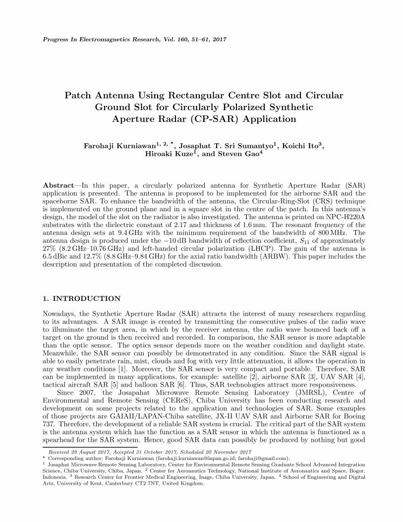
The antenna is printed in double substrates. The patch antenna functions as a radiator of the antennaset in the front layer, with the feed line design set on the backside of the first substrate, and then theground-plane set on the second substrate. The patch antenna is designed with circular shape, and theradius of the patch is r = 4.925 mm, then the length and width of the patch antenna are represented,l = 32.0125 mm. In the middle of the patch antenna lies the square-shaped slot. Then a pair of squareshapes set on 45◦ to y-axis and −45◦ to x-axis function as truncation factors. Truncation’s factor designis represented by Wt and Lt, Wt = 2.8 mm as the width of the truncation shape and Lt = 3 mm as thedepth of the truncation’s shaped. The dimension of the feeding line is represented by Wf = 4.05 mm,Wf1 = 1.35 mm, Wf2 = 2.025 mm, Wfh = 2 mm, Lf1 = 8mm, Lf2 = 10 mm, Lf3 = 12.5 mm, andLf4 = 14.5 mm. The detailed geometry design of the antenna is shown in Figure 1.
2.1. Design of Circular-Ring-Slot on Ground-plane
The proposed design of the antenna is in the form of a circle-shaped patch with the truncation and asmall square one functioned as a slot set in the centre of the patch. The unique part of this design liesin the CRS on the ground-plane which is combined with the square slot in the centre patch having thefunction of enhancing the bandwidth. This antenna is designed with double layers. The front layer isset as a radiation patch, and then the feeding line set on the backside of the front layer. The backsideof the bottom layer is used as the place for the ground plane, and on that ground plane it is functioned
Progress In Electromagnetics Research, Vol. 160, 2017 53
P Slastic crews
93.48 mml
93
.49
mm
l
y
x
11.83 mmwf
wf1
Lf2Lf1
Lf3
Lf4
wf2
wfh wfh
w t
r
atchP
eed-lineF
wg
Circular-Slotz
x
ground
θh1
h2 ubstrateS
ubstrateS
wp
rwg
( ide iew)S V
( op iew)T V
ubstrateS
Lt
Figure 1. Detail design of the antenna.
as a place of the CRS. The antenna design is etched on the substrate with dielectric constant of 2.17,thickness h of 1.6 mm and loss of tangent of 0.0005.
2.1.1. The Circular-Ring-Slot Geometry
Many methods are applied to enhance the impedance bandwidth, AR bandwidth and gain, for example,slot microstrip antenna [11–13], gain enhancement with air gap and foam [14–17], and bandwidthimprovement using metamaterial [18]. In this design, CRS on the ground slot and square slot on thepatch of antenna are proposed to enhance the impedance bandwidth, AR bandwidth and gain. Tocomplete the investigation, the variety of design of the circular slot on the ground plane is presented inthis section.
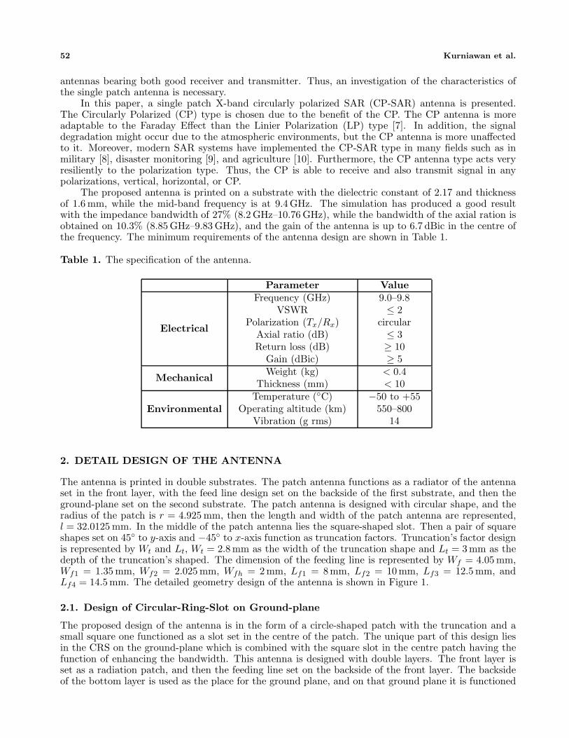
The ground-plane is designed with four models. The design of model 1 has the widest CRS amongothers. The width of the circular slot of model 1 is Rw = 1mm which is represented with R1 = 14.5 mmand R2 = 15.5 mm. Then, the CRS of model 2 is constructed with R1 = 15.4 mm and R2 = 15.5 mm,which means that the width of Rw is 0.1 mm. The CRS of model 3 is the smaller among the others,with R1 = 13.5 mm and R2 = 13.3 mm. The last improvement for ground plane is the plain groundplane without the CRS. Figure 2 shows the designs of the CRS on the ground plane.
2.1.2. Effect of the Circular-Ring-Slot
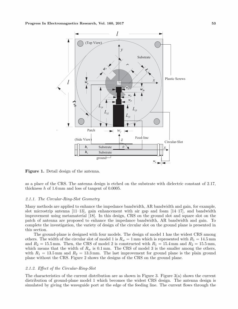
The characteristics of the current distribution are as shown in Figure 3. Figure 3(a) shows the currentdistribution of ground-plane model 1 which becomes the widest CRS design. The antenna design issimulated by giving the waveguide port at the edge of the feeding line. The current flows through the

54 Kurniawan et al.
R1
R2
Rw
R1
Rw
R2
R1
R2
Rw
(a) (b) (c)
Figure 2. Design of circular-ring-slot (CRS). (a) Model 1. (b) Model 2. (c) Model 3.
(a) (b)
(c) (d)
Figure 3. Current distribution. (a) Ground-plane model 1. (b) Ground-plane model 2. (c) Ground-plane model 3. (d) Ground-plane model 4.
Progress In Electromagnetics Research, Vol. 160, 2017 55
feeding line towards the patch-shaped one, then this patch acts as the radiator of the antenna. Lateron, the current is spreading on the patch radiator to make a wave rotation. Nonetheless, this circularmotion of the current is not strong enough, thus the AR cannot yield less than 3dB. In this model, theCRS creates a gap of the cooper on the ground-plane and then continues in the current tracing of theslot in a circular movement. The current is stuck at this CRS and creates a boundary.
Figure 3(b) shows the current distribution of the ground-plane model 2. The current flows fromthe bottom of the feeding line to the center of the antenna. Then, it is distributed to the patch radiator.Evidently, it shows the current distribution which circulates to the left-hand side. Afterward, Figure 3(c)shows the current distribution of the ground-plane model 3. The current’s flow starts from the feedingline. Then, the current spread is more evenly distributed across the surface, and its case is similar tomodel 1. The ground-plane model 4 shown in Figure 3(d) shows the ground-plane design for model4 which is designed without any slot. The purpose of the design is investigating the diversity of thecharacteristics of the antenna as it is set either with or without a slot. The characteristic of the currentdistribution of ground-plane model 4 is similar to that of the ground-plane of model 2.
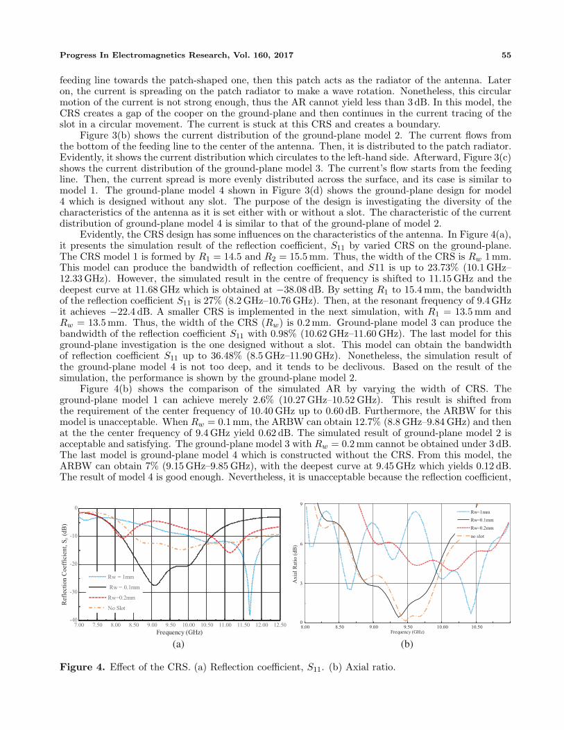
Evidently, the CRS design has some influences on the characteristics of the antenna. In Figure 4(a),it presents the simulation result of the reflection coefficient, S11 by varied CRS on the ground-plane.The CRS model 1 is formed by R1 = 14.5 and R2 = 15.5 mm. Thus, the width of the CRS is Rw 1 mm.This model can produce the bandwidth of reflection coefficient, and S11 is up to 23.73% (10.1 GHz–12.33 GHz). However, the simulated result in the centre of frequency is shifted to 11.15 GHz and thedeepest curve at 11.68 GHz which is obtained at −38.08 dB. By setting R1 to 15.4 mm, the bandwidthof the reflection coefficient S11 is 27% (8.2 GHz–10.76 GHz). Then, at the resonant frequency of 9.4 GHzit achieves −22.4 dB. A smaller CRS is implemented in the next simulation, with R1 = 13.5 mm andRw = 13.5 mm. Thus, the width of the CRS (Rw) is 0.2 mm. Ground-plane model 3 can produce thebandwidth of the reflection coefficient S11 with 0.98% (10.62 GHz–11.60 GHz). The last model for thisground-plane investigation is the one designed without a slot. This model can obtain the bandwidthof reflection coefficient S11 up to 36.48% (8.5 GHz–11.90 GHz). Nonetheless, the simulation result ofthe ground-plane model 4 is not too deep, and it tends to be declivous. Based on the result of thesimulation, the performance is shown by the ground-plane model 2.
Figure 4(b) shows the comparison of the simulated AR by varying the width of CRS. Theground-plane model 1 can achieve merely 2.6% (10.27 GHz–10.52 GHz). This result is shifted fromthe requirement of the center frequency of 10.40 GHz up to 0.60 dB. Furthermore, the ARBW for thismodel is unacceptable. When Rw = 0.1 mm, the ARBW can obtain 12.7% (8.8 GHz–9.84 GHz) and thenat the the center frequency of 9.4 GHz yield 0.62 dB. The simulated result of ground-plane model 2 isacceptable and satisfying. The ground-plane model 3 with Rw = 0.2 mm cannot be obtained under 3 dB.The last model is ground-plane model 4 which is constructed without the CRS. From this model, theARBW can obtain 7% (9.15 GHz–9.85 GHz), with the deepest curve at 9.45 GHz which yields 0.12 dB.The result of model 4 is good enough. Nevertheless, it is unacceptable because the reflection coefficient,
7.00 7.50 8.00 8.50 9.00 9.50 10.00 10.50 11.00 11.50 12.00 12.50-40
-30
-20
-10
0
Frequency (GHz)
Rw = 1mm
Rw = 0.1mm
Rw=0.2mm
No Slot
Ref
lect
ion C
oef
fici
ent,
S(d
B)
11
8.00 8.50 9.00 9.50 10.00 10.500
3
6
9
Frequency (GHz)
Rw=1mm
Rw=0.1mm
Rw=0.2mm
no slot
Axia
l R
atio
(dB
)
(a) (b)
Figure 4. Effect of the CRS. (a) Reflection coefficient, S11. (b) Axial ratio.
56 Kurniawan et al.
8.00 8.50 9.00 9.500
2
4
6
8
Frequency (GHz)
Rw=1mm
Rw=0.1mm
Rw=0.2mm
no slot
Gai
n (
dB
ic)
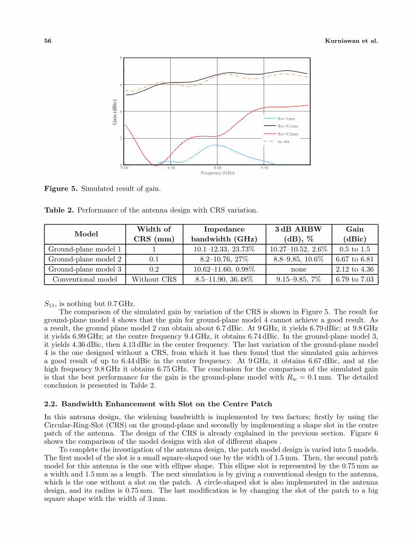
Figure 5. Simulated result of gain.
Table 2. Performance of the antenna design with CRS variation.
ModelWidth of
CRS (mm)Impedance
bandwidth (GHz)3 dB ARBW
(dB), %Gain(dBic)
Ground-plane model 1 1 10.1–12.33, 23.73% 10.27–10.52, 2.6% 0.5 to 1.5Ground-plane model 2 0.1 8.2–10.76, 27% 8.8–9.85, 10.6% 6.67 to 6.81Ground-plane model 3 0.2 10.62–11.60, 0.98% none 2.12 to 4.36Conventional model Without CRS 8.5–11.90, 36.48% 9.15–9.85, 7% 6.79 to 7.03
S11, is nothing but 0.7 GHz.The comparison of the simulated gain by variation of the CRS is shown in Figure 5. The result for
ground-plane model 4 shows that the gain for ground-plane model 4 cannot achieve a good result. Asa result, the ground plane model 2 can obtain about 6.7 dBic. At 9GHz, it yields 6.79 dBic; at 9.8 GHzit yields 6.99 GHz; at the centre frequency 9.4 GHz, it obtains 6.74 dBic. In the ground-plane model 3,it yields 4.36 dBic, then 4.13 dBic in the center frequency. The last variation of the ground-plane model4 is the one designed without a CRS, from which it has then found that the simulated gain achievesa good result of up to 6.44 dBic in the center frequency. At 9 GHz, it obtains 6.67 dBic, and at thehigh frequency 9.8 GHz it obtains 6.75 GHz. The conclusion for the comparison of the simulated gainis that the best performance for the gain is the ground-plane model with Rw = 0.1 mm. The detailedconclusion is presented in Table 2.
2.2. Bandwidth Enhancement with Slot on the Centre Patch
In this antenna design, the widening bandwidth is implemented by two factors; firstly by using theCircular-Ring-Slot (CRS) on the ground-plane and secondly by implementing a shape slot in the centrepatch of the antenna. The design of the CRS is already explained in the previous section. Figure 6shows the comparison of the model designs with slot of different shapes .
To complete the investigation of the antenna design, the patch model design is varied into 5 models.The first model of the slot is a small square-shaped one by the width of 1.5 mm. Then, the second patchmodel for this antenna is the one with ellipse shape. This ellipse slot is represented by the 0.75 mm asa width and 1.5 mm as a length. The next simulation is by giving a conventional design to the antenna,which is the one without a slot on the patch. A circle-shaped slot is also implemented in the antennadesign, and its radius is 0.75 mm. The last modification is by changing the slot of the patch to a bigsquare shape with the width of 3 mm.
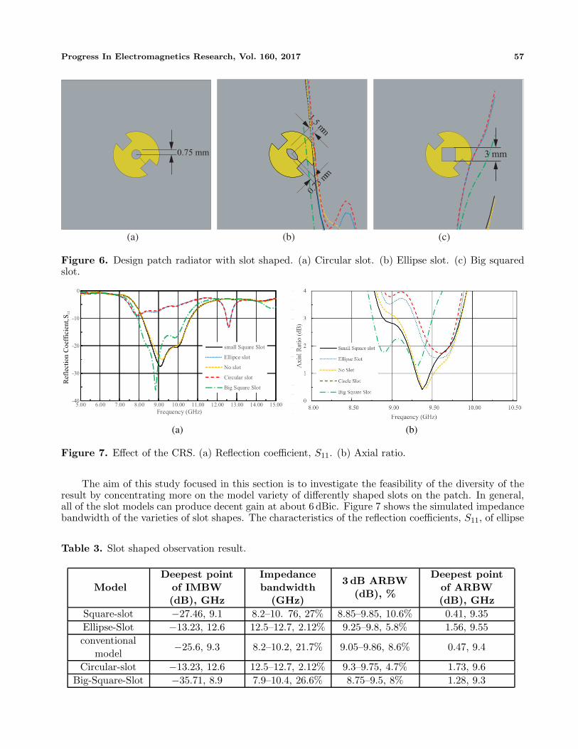
Progress In Electromagnetics Research, Vol. 160, 2017 57
0.75 mm
1.5 mm
0.75
m m
3 mm
(a) (b) (c)
Figure 6. Design patch radiator with slot shaped. (a) Circular slot. (b) Ellipse slot. (c) Big squaredslot.
-40
-30
-20
-10
0
5.00 6.00 7.00 8.00 9.00 10.00 11.00 12.00 13.00 14.00 15.00
Frequency (GHz)
small Square Slot
Ellipce slot
No slot
Circular slot
Big Square Slot
Ref
lect
ion C
oef
fici
ent,
S11
(a) (b)
Figure 7. Effect of the CRS. (a) Reflection coefficient, S11. (b) Axial ratio.
The aim of this study focused in this section is to investigate the feasibility of the diversity of theresult by concentrating more on the model variety of differently shaped slots on the patch. In general,all of the slot models can produce decent gain at about 6 dBic. Figure 7 shows the simulated impedancebandwidth of the varieties of slot shapes. The characteristics of the reflection coefficients, S11, of ellipse
Table 3. Slot shaped observation result.
ModelDeepest point
of IMBW(dB), GHz
Impedancebandwidth
(GHz)
3 dB ARBW(dB), %
Deepest pointof ARBW(dB), GHz
Square-slot −27.46, 9.1 8.2–10. 76, 27% 8.85–9.85, 10.6% 0.41, 9.35Ellipse-Slot −13.23, 12.6 12.5–12.7, 2.12% 9.25–9.8, 5.8% 1.56, 9.55conventional
model−25.6, 9.3 8.2–10.2, 21.7% 9.05–9.86, 8.6% 0.47, 9.4
Circular-slot −13.23, 12.6 12.5–12.7, 2.12% 9.3–9.75, 4.7% 1.73, 9.6Big-Square-Slot −35.71, 8.9 7.9–10.4, 26.6% 8.75–9.5, 8% 1.28, 9.3
58 Kurniawan et al.
slot are similar to that of the small square slot. The low frequency and high frequency are exactly in thesame place at 8.2 GHz to 10.76 GHz of about 27%. The only thing which makes both characteristics ofthe reflection coefficient, S11, different is the depth of the curve of the graphic. The detailed conclusionof the slot-shape observation is presented in Table 3.
3. FABRICATION AND MEASUREMENT RESULT
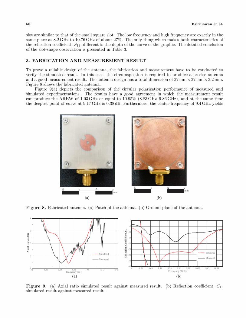
To prove a reliable design of the antenna, the fabrication and measurement have to be conducted toverify the simulated result. In this case, the circumspection is required to produce a precise antennaand a good measurement result. The antenna design has a total dimension of 32mm×32mm×3.2 mm.Figure 8 shows the fabricated antenna.
Figure 9(a) depicts the comparison of the circular polarization performance of measured andsimulated experimentations. The results have a good agreement in which the measurement resultcan produce the ARBW of 1.03 GHz or equal to 10.95% (8.83 GHz–9.86 GHz), and at the same timethe deepest point of curve at 9.17 GHz is 0.38 dB. Furthermore, the center-frequency of 9.4 GHz yields
(a) (b)
Figure 8. Fabricated antenna. (a) Patch of the antenna. (b) Ground-plane of the antenna.
0
1
2
3
4
8.5 8.83 9.15 9.48 9.8 10.13 10.45Frequency (GH)
Simulated
Measured
Axia
l R
atio
(dB
)
-40
-35
-30
-25
-20
-15
-10
-5
0
8 8.31 8.63 8.94 9.25 9.56 9.88 10.19 10.5 10.81
Frequency (GHz)
Simulated
MeasuredRef
lect
ion C
oef
fici
ent,
S11
(a) (b)
Figure 9. (a) Axial ratio simulated result against measured result. (b) Reflection coefficient, S11
simulated result against measured result.
Progress In Electromagnetics Research, Vol. 160, 2017 59
1.28 dB of AR. Meanwhile, the simulated experimentation can produce AR with the bandwidth of0.97 GHz or equal to 10.3% (8.86 GHz–9.83 GHz), and the deepest point of curve at 9.34 GHz is 0.43 dBand at the resonant frequency of 0.63 dB. The simulated and measured results meet the suitability.
The minimum requirement of the bandwidth of the reflection coefficient S11 under −10 dB is0.8 GHz. As shown in Figure 9(b), the simulation and measurement can produce acceptable resultscompared to the minimum requirement. The impedance bandwidth is up to 1.51 GHz or equal to16% (8.9 GHz–10.41 GHz) of the measurement. At the centre frequency, the measured result is up
0.00
2.00
4.00
6.00
8.00
8.50 8.81 9.13 9.44 9.75 10.06 10.38
Simulated
Measured
Gai
n (
dB
ic)
(a) (b)
Figure 10. (a) Simulated and measured gain of proposed antenna. (b) Simulated and MeasuredVSWR.
Measured LHCP
Measured RHCP
(a)
Measured LHCP
Measured RHCP
(b)
Measured LHCP
Measured RHCP
(c)
Measured LHCP
Measured RHCP
(d)
Figure 11. Measured and simulated radiation pattern of proposed X-band antenna: (a) 9.2 GHz; (b)9.4 GHz; (c) 9.6 GHz; (d) 9.8 GHz.
60 Kurniawan et al.
to −18.19 dB, while the deepest curve is at 9.46 GHz of 18.48 dB. However, this measurement resultdecreases compared to the simulated one. The impedance bandwidth of the measurement yields2.56 GHz or 27% (8.2 GHz–10.76 GHz), −27.7 dB of the centre frequency, and the deepest point ofcurve is at 8.91 GHz up to −36.36 dB.
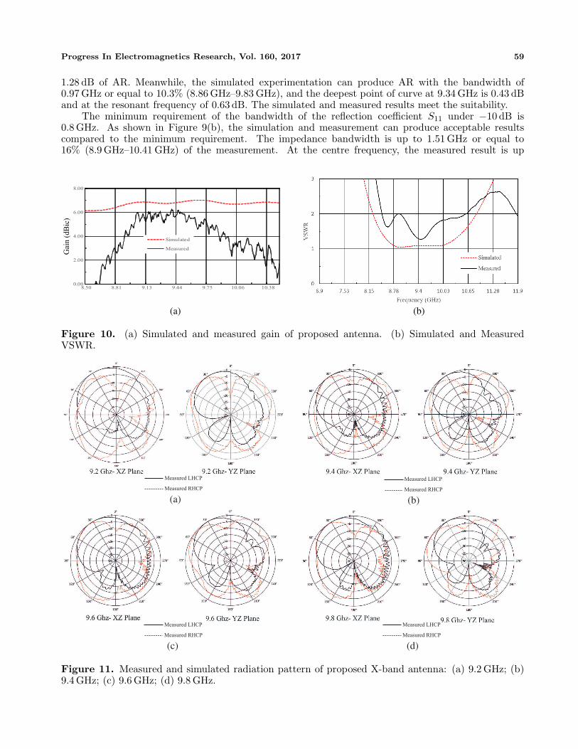
Figure 10(a) highlights the simulated and measured gains. The minimum requirement of gain of theantenna design is approximately 5 dBic. The results of simulation and measurement meet the minimumrequirement. The simulation can achieve a quite good result, which is about 7.4 dBic at the resonantfrequency, 6.81 dBic at the lower frequency and 6.69 dBic at the higher frequency. On the other hand,the measured result shows a reduction; however it remains an acceptable one. In the lower frequency, ityields 5.3 dBic, while in the higher frequency it is 4.91 dBic, and this point (9.8 GHz-higher frequency)also becomes the lower point of gain. However, this result is still acceptable due to the average value ofthe measured gain at desired frequency of about 5.6 dBic to the minimum requirement of the antennadesign.
The result for VSWR also shows the indication of good agreement as depicted in Figure 10(b).This is an indication that the simulated and measured results are acceptable to < 2 in the desiredfrequency. The average value of simulated result is 1.07 and 1.5 for the measured result. Figure 11shows the LHCP against the RHCP radiation pattern in the X-Z plane and Y -Z plane at four discretefrequencies; 9.2 GHz, 9.4 GHz, 9.6 GHz and 9.8 GHz.
4. CONCLUSION
CRS has managed to enhance the performance of the reflection coefficient and the ARBW, and it alsoproduces a good gain. Evidently, ground-plane model 2 with 0.1 mm CRS can enhance the impedancebandwidth under −10 dB of 27% and at 3-dB which obtains 12.7 dB and the gain up to 6.7 dBic. Asmall square slot with the diameter of 1.5 mm is suitable for the proposed antenna. It can producethe impedance bandwidth under −10 dB of 27%. The effect of 1.5 square slot can reach minimumrequirement of the impedance bandwidth, and it has a good agreement with the minimum requirement.It can produce the impedance bandwidth up to 16% and 3-dB ARBW obtaining 10.95%. It shows aslightly low result compared to the simulated one; however, it is still considered as an acceptable one.The imprecise measured result is due to fabrication errors (drilling, cutting, soldering and etching). Tosum it up, this novel antenna design has a good performance.
ACKNOWLEDGMENT
This research is supported in parts by the Japan Science and Technology Agency (JST) JapanInternational Cooperation Agency (JICA) FY2010-2016 Science and Technology Research Partnershipfor Sustainable Development (SATREPS); the European Space Agency (ESA) Earth ObservationCategory 1 under Grant 6613; the 4th Japan Aerospace Exploration Agency (JAXA) ALOS ResearchAnnouncement under Grant 1024; the 6th JAXA ALOS Research Announcement under Grant 3170; theJapanese Government National Budget Ministry of Education and Technology (MEXT) FY2015-2017under Grant 2101; Chiba University Strategic Priority Research Promotion Program FY2016-FY2018;Taiwan National Space Organization (NSPO) under Grant NSPIO-S-105096; and Indonesian NationalInstitute of Aeronautics and Space (LAPAN); National Institute for Environmental Studies (NIES) forASTER images; GSI for GPS ground measurement data.
REFERENCES
1. Ulaby, F. T., R. K. Moore, and A. K. Fung, Microwave Remote Sensing: Active and Passive, Vol. I,Artech House, Norwood, 1981.
2. James, Y. Y., et al., “An X-band SAR satellite payload design with low cost approach for disastersmanagement,” 2015 IEEE 5th APSAR, 15568731, 2015.
3. Natele. A., P. Berardino, C. Esposito, and S. Perna, “Airborne SAR for high resolution imaging,”2017 Joint Urban Remote Sensing Event (JURSE), 16868028, 2017.

Progress In Electromagnetics Research, Vol. 160, 2017 61
4. Sri Sumantyo, J. T., “Development of circularly polarized Synthetic Aperture Radar onboardUnmanned Aerial Vehicle (CP-SAR UAV),” 2012 IEEE IGARSS , 13133238, 2012.
5. Wang, N., Y. Li, Y. Bu, and J. Chen, “SAR sensor employment planning for tactical aircraft,”2010 The 2nd ICCAE , 11259605, 2010.
6. Yang, H., L. Teng, Y. Huang, J. Yang, and X. Yang, “Multi-spotlight balloon SAR: An interestingmicrowave remote sensing mission for distributed monitoring,” 2013 IEEE IGARSS , 14059446,2014.
7. Osanai, Y., J. T. Sri Sumantyo, and Z. Baharuddin, “Development of spaceborne antenna forcircularly polarized SAR using Kevlar honeycomb core,” 2015 IEEE 5th Asia-Pacific Conferenceon APSAR, 15558266, 2015.
8. Anter, Y. M., M. A. Henry, and G. C. McCormick, “Circular polarization for remote sensing ofprecipitation: Polarization diversity work at the National Research Council of Canada,” IEEEAntennas and Propagation Magazine, Vol. 34, No. 6, 1345–1354, 1989.
9. Sri Sumantyo, J. T., H. Wakabayashi, A. Iwasaki, F. Takahashi, H. Ohmae, H. Watanabe,R. Tateishi, F. Nishio, M. Baharuddin, and P. R. Akbar, “Development of circularly polarizedsynthetic aperture radar onboard microsatellite (muSAT CP-SAR),” PIERS Proceedings, 382–385,Beijing, China, Mar. 23–27, 2009.
10. Sri Sumantyo, J. T., “Development of Circularly Polarized Synthetic Aperture Radar (CP-SAR)onboard small satellite,” PIERS Proceedings, 334–341, Marrakesh, Morocco, Mar. 20–23, 2011.
11. Kurniawan, F., J. T. Sri Sumantyo, G. S. Prabowo, and A. Munir, “Wide bandwidth left-handedcircularly polarized printed antenna with crescent slot,” 2017 Progress In Electromagnetics ResearchSymposium (PIERS), 1047–1050, St Petersburg, Russia, May 22–25, 2017.
12. Ghali, H. A. and T. A. Moselhy, “Broad-banda and cirularly polarized space-filling-based slotantennas,” IEEE Transactions on Microwave Theory and Techniques, Vol. 53, No. 6, Jun. 2005.
13. Taher, H. and R. Farrell, “Broadband high gain SIW cavity square slot antenna for X-bandapplications,” Antennas and Propagation Conference (LAPC), Loughborough, 2016.
14. Jamlos, M. F., T. Bin Abdul Rahman, M. R. Kamarudin, M. T. Ali, M. Nor Md Tan, andP. Saad, “The gain effects of air gap quadratic aperture-coupled microstrip antenna array,” PIERSProceedings, 462–465, Cambridge, USA, Jul. 5–8, 2010.
15. Ali, M. T., H. Jaafar, S. Subahir, and A. L. Yusof, “Gain enhancement of air substrates at 5.8 GHzfor microstrip antenna array,” Electromagnetic Compatibility, Vol. 18, No. 1, 477–480, 2012.
16. Raut, R. and K. Talandage, “Bandwidth and gain enhancement of rectangular MSA byusing parasitic patch and capacitive feeding technique for wideband application,” InternationalConference on Microwave, Optical and Communcation Engineering , IIT Bhubaneswar, India,Dec. 2015.
17. Ta, S. X. and T. K. Nguyuen, “AR bandwidth and gain enhancements of patch antenna usingsingle dielectric superstrate,” IEEE Electronics Letters, Vol. 53, No. 15, 2017.
18. Dai, Y. L., et al., “A novel compact ultra-wideband metamaterial-based microstrip antenna,”IMWS-AMP , 2016.