Research Article Analysis of Vertical-Horizontal...
12
Research Article Analysis of Vertical-Horizontal Coupling Vibration Characteristics of Rolling Mill Rolls Based on Strip Dynamic Deformation Process Dongxiao Hou, 1 Rongrong Peng, 2 and Haoran Liu 2 1 School of Control Engineering, Northeastern University at Qinhuangdao, Qinhuangdao, Hebei 066004, China 2 Institute of Information Technology and Engineering, Yanshan University, Qinhuangdao, Hebei 066004, China Correspondence should be addressed to Dongxiao Hou; [email protected] Received 26 October 2013; Revised 21 March 2014; Accepted 21 March 2014; Published 6 April 2014 Academic Editor: Valder Steffen Copyright © 2014 Dongxiao Hou et al. is is an open access article distributed under the Creative Commons Attribution License, which permits unrestricted use, distribution, and reproduction in any medium, provided the original work is properly cited. Nonlinear dynamic rolling forces in the vertical and horizontal directions are, respectively, established, considering the impact of vertical and horizontal directions vibration of rolls. en a vertical-horizontal coupling nonlinear vibration dynamic model of rolling mill rolls is proposed, based on the interactions between this dynamic rolling force and mill structure. e amplitude- frequency equations of the main resonance and inner resonance are carried out by using multiple-scale method. e characteristics of amplitude frequency under nonlinear stiffness, damping, and amplitude of the disturbance are obtained by adopting the actual parameters of 1780 rolling mills. Finally, the bifurcation behavior of the system is studied, and it is found that many dynamic behaviors such as period, period-3 motion, and chaos exist in rolling mill, and this behavior could be restrained effectively by choosing proper system parameters. 1. Introduction e vibration of rolling mill oſten occurs in rolling process. e occurrence of vibration not only affects the quality of rolling products, but also leads to breakdown of the rolling equipment. In order to understand the vibration behaviors of mills, a number of models have been developed during the past few decades [1–5]. However, in most open literatures, the vibrations in the horizontal direction and in the vertical direction are studied separately. In recent years, the coupling relationship in rolling mill is proposed; Hu et al. studied the linear vibration characteristics in vertical and horizontal direction [6]. Yang et al. studied the stability of coupling dynamic vertical model of cold rolling mill, which consists of the rolling process model, the mill roll stand structure model, and the hydraulic servo system model [7]. In the process of studying rolling mill vibration, modeling of rolling force dir- ectly determines the accuracy of vibration model. In the early years, the rolling force in the rolling process is quasistatic, which assumes that only dynamic variations in roll spacing produce variations in force, strip speed, and strip thickness to those occurring under steady-state conditions [8–10]. Yun et al. proposed a dynamic model of rolling mill, which consid- ers the rate variation of change of the roll spacing. But in order to simplify calculation, he only selected the linear section of rolling force by using Taylor formula [11]. In fact, most of the literatures adopted the method of Yun, by taking the rolling force as a linear factor and neglecting nonlinear section. In this paper, nonlinear dynamic rolling forces in the vertical and horizontal directions are proposed, respectively. en a vertical-horizontal coupling vibration dynamic model of rolling mill rolls is constructed based on the interac- tions between this dynamic nonlinear rolling force and mill structure. en the amplitude-frequency characteristics of the main resonance and inner resonance are analyzed under the nonlinear stiffness, damping, and the amplitude of the disturbance stiffness. Finally, the conditions of different dynamical motions are obtained by analyzing bifurcation behavior of the system, which could provide theoretical base for understanding of vibration mechanism of mill. Hindawi Publishing Corporation Shock and Vibration Volume 2014, Article ID 543793, 11 pages http://dx.doi.org/10.1155/2014/543793
Transcript of Research Article Analysis of Vertical-Horizontal...

Research ArticleAnalysis of Vertical-Horizontal CouplingVibration Characteristics of Rolling Mill Rolls Based onStrip Dynamic Deformation Process
Dongxiao Hou1 Rongrong Peng2 and Haoran Liu2
1 School of Control Engineering Northeastern University at Qinhuangdao Qinhuangdao Hebei 066004 China2 Institute of Information Technology and Engineering Yanshan University Qinhuangdao Hebei 066004 China
Correspondence should be addressed to Dongxiao Hou houdongxiao1982163com
Received 26 October 2013 Revised 21 March 2014 Accepted 21 March 2014 Published 6 April 2014
Academic Editor Valder Steffen
Copyright copy 2014 Dongxiao Hou et alThis is an open access article distributed under the Creative Commons Attribution Licensewhich permits unrestricted use distribution and reproduction in any medium provided the original work is properly cited
Nonlinear dynamic rolling forces in the vertical and horizontal directions are respectively established considering the impactof vertical and horizontal directions vibration of rolls Then a vertical-horizontal coupling nonlinear vibration dynamic modelof rolling mill rolls is proposed based on the interactions between this dynamic rolling force and mill structure The amplitude-frequency equations of the main resonance and inner resonance are carried out by usingmultiple-scale methodThe characteristicsof amplitude frequency under nonlinear stiffness damping and amplitude of the disturbance are obtained by adopting the actualparameters of 1780 rolling mills Finally the bifurcation behavior of the system is studied and it is found that many dynamicbehaviors such as period period-3 motion and chaos exist in rolling mill and this behavior could be restrained effectively bychoosing proper system parameters
1 Introduction
The vibration of rolling mill often occurs in rolling processThe occurrence of vibration not only affects the quality ofrolling products but also leads to breakdown of the rollingequipment In order to understand the vibration behaviorsof mills a number of models have been developed during thepast few decades [1ndash5] However inmost open literatures thevibrations in the horizontal direction and in the verticaldirection are studied separately In recent years the couplingrelationship in rolling mill is proposed Hu et al studiedthe linear vibration characteristics in vertical and horizontaldirection [6] Yang et al studied the stability of couplingdynamic vertical model of cold rolling mill which consists ofthe rolling process model themill roll stand structuremodeland the hydraulic servo system model [7] In the process ofstudying rolling mill vibration modeling of rolling force dir-ectly determines the accuracy of vibrationmodel In the earlyyears the rolling force in the rolling process is quasistaticwhich assumes that only dynamic variations in roll spacing
produce variations in force strip speed and strip thicknessto those occurring under steady-state conditions [8ndash10] Yunet al proposed a dynamicmodel of rollingmill which consid-ers the rate variation of change of the roll spacing But in orderto simplify calculation he only selected the linear section ofrolling force by using Taylor formula [11] In fact most of theliteratures adopted the method of Yun by taking the rollingforce as a linear factor and neglecting nonlinear section
In this paper nonlinear dynamic rolling forces in thevertical and horizontal directions are proposed respectivelyThen a vertical-horizontal coupling vibration dynamicmodelof rolling mill rolls is constructed based on the interac-tions between this dynamic nonlinear rolling force and millstructure Then the amplitude-frequency characteristics ofthe main resonance and inner resonance are analyzed underthe nonlinear stiffness damping and the amplitude of thedisturbance stiffness Finally the conditions of differentdynamical motions are obtained by analyzing bifurcationbehavior of the system which could provide theoretical basefor understanding of vibration mechanism of mill
Hindawi Publishing CorporationShock and VibrationVolume 2014 Article ID 543793 11 pageshttpdxdoiorg1011552014543793
2 Shock and Vibration
y
R
O x
120579
R
xc
xc
lx
1
h1h2h0
0
120591b hx
120591f
xn
x2
x1
yc
yc
Figure 1 The dynamic deformation process of strip
2 Nonlinear Rolling Force Based onDynamic Deformation Process of Strip
21 Parameters of Deformation Zone under Vibration Condi-tions Considering the influence of vertical and horizontalvibration of roll the dynamic deformation process of strip isshown in Figure 1
As shown in Figure 1 the solid line represents the steady-state position of roll and the dashed line is the position of rollunder vibration conditions
Considering the elastic flattening of the rolls the roll gapis treated as a parabolic curve [11] Based on Von Karmanrsquosstudy [10] considering the vertical displacement of rolls thethickness ℎ
119909of the rolling mill at any arbitrary position 119909 is
ℎ119909= ℎ0+ 2119910119888+(119909 minus 119909
119888)2
119877 (1)
Assuming that the thickness ℎ1at entry position is con-
stant the entry coordinate of strip can be derived from (1) as
1199091= 119909119888+ radic119877 (ℎ
1minus ℎ0minus 2119910119888) (2)
Then the velocity at entry position along horizontaldirection can be derived form (2) as
1= 119888minus (ℎ1minus ℎ0minus 2119910119888)minus12
11987712
119910 (3)
Considering the influence of roll horizontal vibration theequivalent velocity at the entry position will be composed oftwoparts the entrance velocity V
1of strip and entrance rate
1
at entry position and it can be expressed as
V10158401= V1minus 1 (4)
From Figure 1 the exit thickness of strip under vibrationconditions can be obtained as
ℎ2= ℎ0+ 2119910119888 (5)
Under vibration conditions the bulk of metal in defor-mation zone is not constant so the equation of constant massthroughput is no longer suitable for vibration conditionsThen a new principal of metal flow per second will be pro-posed and the dynamic flow at any arbitrary position 119909 canbe expressed as
V119909ℎ119909= V10158401ℎ1minus Δ (6)
where V119909ℎ119909is equivalent exit flow at any arbitrary position 119909
and V10158401ℎ1is equivalent entry flow
Where the volume in deformation zone range from 1199091to
119909 can be expressed as
Δ119881 =1
2(1199091minus 119909) (ℎ
1+ ℎ119909) minus 2119877
2 arcsin119897119909
119877+1
4119897119909radic41198772 minus 1198972
119909
(7)
where
119897119909=radic(1199091minus 119909)2
+(ℎ1minus ℎ119909)2
4
(8)
the derivative of (7) can be obtained as
Δ =1
21(ℎ1+ ℎ119909) +
1
2(1199091minus 119909) ℎ
119909
minus21198772 119897119909
radic1198772 minus 1198972119909
+1
4
119897119909radic41198772 minus 1198972
119909minus1
41198972
119909
119897119909
radic41198772 minus 1198972119909
(9)
where
ℎ119909= 2 119910119888minus2119888(119909 minus 119909
119888)
119877
119897119909=4 (1199091minus 119909)
1minus ℎ119909(ℎ1minus ℎ119909)
2radic4(1199091minus 119909)2
+ (ℎ1minus ℎ119909)
(10)
Shock and Vibration 3
Then the speed V119909at any arbitrary position can be
expressed as
V119909=V10158401ℎ1minus Δ
ℎ119909
(11)
When the horizontal component of surface speed of roll isequal to (11) namely
V119909=V119877
119877
radic1198772 minus (119909 minus 119909119888)2
(12)
at the moment the position 119909 is the position of neutral point119909119899in (12) Due to119877 ≫ (119909minus119909
119888) and |119909minus119909
119888| ≪ 1 and neglecting
high-order item (119909 minus 119909119888)2 the neutral point can be derived as
119909119899= 1199091minus
(ℎ1minus ℎ2)radic(41198772 minus 2) (1198622 minus 1)
81198772 minus 1198622
(13)
where
119862 = V119877ℎ2minus V10158401ℎ1+1
21(ℎ1+ ℎ2) + 1199091119910119888 (14)
22 Nonlinear Dynamic Rolling Force in Horizontal andVertical Direction According to slabmethod [10] take a sliceof the strip in Figure 2
Based on force balance theory in deformation zone byVon Karman [10] the force balance expression in horizontaldirection can be expressed as
119889ℎ119909
119889119909(119875 + 120591
119909) + ℎ119909
119889120591119909
119889119909plusmn 2119865120583= 0 (15)
where 119865120583= 120583120575 when 119909 lt 119909
119899 take the negative and when
119909 gt 119909119899 take the positive
By taking account of the assumption of homogeneousdeformation [11] the distribution of stress can be written byvon Mises yield criterion as follows
119889120591119909
119889119909=2120575
ℎ119909
(∓120583 minus2 (119909 minus 119909
119888)
119877) (16)
Integrating (16) the tension 120591119909can be express as
120591119909= 120591119887+ int
119909
1199091
2120575
ℎ119909
(∓120583 minus2 (119909 minus 119909
119888)
119877)119889119909 (17)
The unit rolling force by (17) can be expressed as
119875 (119909) = 2120575 minus [120591119887+ int
119909
1199091
2120575
ℎ119909
(∓120583 minus2 (119909 minus 119909
119888)
119877)119889119909] (18)
The rolling force in horizontal and vertical direction canbe obtained as follows
119865119909= minusint
1199091
1199092
119875 (119909) tan 120579 119889119909 + int
1199091
1199092
∓120583120575 119889119909
119865119910= int
1199091
1199092
119875 (119909) 119889119909 + int
1199091
1199092
∓120583120575 tan 120579 119889119909(19)
where
tan 120579 =119909 minus 119909119888
radic1198772 minus (119909 minus 119909119888)2
(20)
In (19) integrating zone is composed of two sectionsnamely 119909
2sim 119909119899and 119909
119899sim 1199091 Integrating (19) we obtained
119865119909= minus 120583120575ℎ
2radic
119877
ℎ0+ 2119910119888
[2tanminus1 (119909119899minus 119909119888
radic119877ℎ0+ 2119877119910
119888
)
minustanminus1 (1199091minus 119909119888
radic119877ℎ0+ 2119877119910
119888
)]
+120591119887
2(ℎ1minus ℎ2) minus 120575ℎ
2ln ℎ1
ℎ2
119865119910= [2120575 ln(ℎ1
ℎ2
) minus 2120575 minus 120591119887] (1199091minus119909119888)
+ 4120575radic119877ℎ0+ 2119877119910
119888tanminus1 (
1199091minus 119909119888
radic119877ℎ0+ 2119877119910
119888
)
+ 2120583120575radic119877
ℎ0+ 2119910119888
(1199091minus119909119888)
times [2tanminus1 (119909119899minus 119909119888
radic119877ℎ0+ 2119877119910
119888
) minus tanminus1 (1199091minus 119909119888
radic119877ℎ0+ 2119877119910
119888
)]
+ 120583120575119877 ln(ℎ1ℎ2
ℎ2119899
)
(21)
3 The Vertical-Horizontal CouplingDynamic Equation of Mill Rolls
Set 1199091198880
and 1199101198880
which are the balance points of rolls in thehorizontal and vertical direction respectively Under steadyconditions
1198880= 0 and 119910
1198880= 0 by using Taylor formula (21)
can be expressed as
119865119909(119909119888 119888 119910119888 119910119888) = 119865119909(1199091198880 0 1199101198880 0) + Δ119865
119909(119909119888 119888 119910119888 119910119888)
119865119910(119909119888 119888 119910119888 119910119888) = 119865119910(1199091198880 0 1199101198880 0) + Δ119865
119910(119909119888 119888 119910119888 119910119888)
(22)
where 119865(1199091198880 0 1199101198880 0) is rolling force when there is no vibra-
tion and Δ119865(119909119888 119888 119910119888 119910119888) is dynamic parts of rolling force
because too many parameters for simplify the calculationtake the parts of first and third order as follows
Δ119865119909(119909119888 119888 119910119888 119910119888)
= 1198861119909119888+ 1198862119888+ 1198863119910119888+ 1198864119910119888+ 11988651199093
119888+ 11988661199103
119888
Δ119865119910(119909119888 119888 119910119888 119910119888)
= 1198871119909119888+ 1198872119888+ 1198873119910119888+ 1198874119910119888+ 11988751199093
119888+ 11988761199103
119888
(23)
4 Shock and Vibration
hx
120591x
F120583
F120583
dx
P
P
hx minus dhx
120591x minus d120591x
Figure 2 The pressure diagram of strip
where
1198861=
120597
120597119909119888
119865119909(1199091198880 0 1199101198880 0)
1198871=
120597
120597119909119888
119865119910(1199091198880 0 1199101198880 0)
1198862=
120597
120597119888
119865119909(1199091198880 0 1199101198880 0)
1198872=
120597
120597119888
119865119910(1199091198880 0 1199101198880 0)
1198863=
120597
120597119910119888
119865119909(1199091198880 0 1199101198880 0)
1198873=
120597
120597119910119888
119865119910(1199091198880 0 1199101198880 0)
1198864=
120597
120597 119910119888
119865119909(1199091198880 0 1199101198880 0)
1198874=
120597
120597 119910119888
119865119910(1199091198880 0 1199101198880 0)
1198865=1
6
1205973
1205971199093119888
119865119909(1199091198880 0 1199101198880 0)
1198875=1
6
1205973
1205971199093119888
119865119910(1199091198880 0 1199101198880 0)
1198866=1
6
1205973
1205971199103119888
119865119909(1199091198880 0 1199101198880 0)
1198876=1
6
1205973
1205971199103119888
119865119910(1199091198880 0 1199101198880 0)
(24)
Based on the assumption that the mass of working rollsare much smaller than that of backup rolls the mass of the
working rolls may be neglected [6] The vertical-horizontalcoupling nonlinear vibration model of rolling mill with non-linear dynamic rolling force is illustrated in Figure 3
The dynamic equation in Figure 3 can be written as
1198981119888+ 1198881119888+ 1198961(119909119888+ 1199091198880) + 119865119909(119909119888 119888 119910119888 119910119888) = 0
1198981119910119888+ 1198882119910119888+ 1198962(119910119888+ 1199101198880) + 119865119910(119909119888 119888 119910119888 119910119888) = 1198791
1198982119888+ 1198883119888+ 1198964(119909119888+ 1199091198880) + 119865119909(119909119888 119888 119910119888 119910119888) = 0
minus1198982119910119888minus 1198884119910119888minus 1198964(119910119888+ 1199101198880) + 119865119910(119909119888 119888 119910119888 119910119888) = 1198792
(25)
Assuming that the structure of rolling mill and vibrationare symmetrical in relation to the rolled strip [6] then thereexist 119896
1= 1198963 1198962= 1198964 1198881= 1198883 1198882= 11988841198981= 1198982 and119879
1= minus1198792
and (25) can be simplified as
1198981119888+ 1198881119888+ 1198961(119909119888+ 1199091198880) + 119865119909(119909119888 119888 2119910119888 2 119910119888) = 0
1198981119910119888+ 1198882119910119888+ 1198962(119910119888+ 1199101198880) + 119865119910(119909119888 119888 2119910119888 2 119910119888) = 1198791
(26)
Under steady conditions the external disturbance force1198791= 0 there exist
119888= 119910119888= 0
119888= 119910119888= 0 and 119909
119888= 119910119888= 0
and the balance equation can be obtained as follows
11989611199091198880+ 119865119909(1199091198880 0 2119910
1198880 0) = 0
11989621199101198880+ 119865119910(1199091198880 0 2119910
1198880 0) = 0
(27)
Substituting (27) into (26) (26) can be expressed as
1198981119888+ 1198881119888+ 1198961119909119888+ Δ119865119909(119909119888 119888 2119910119888 2 119910119888) = 0
1198981119910119888+ 1198882119910119888+ 1198962119910119888+ Δ119865119910(119909119888 119888 2119910119888 2 119910119888) = 1198791
(28)
Shock and Vibration 5
k2c2
k1
k4
k3
c1
c3
c4
m1
m2
T2
T1
Fx
Fy
yc
yc
xc
xc
Figure 3The vertical-horizontal coupling dynamicmodel of rollingmill rolls
Substitute (23) and (27) into (28) and set
1205962
1=(1198961+ 1198861)
1198981
1205721=(1198881+ 1198862)
1198981
1205731=
1198863
1198981
1205741=
1198864
1198981
1205781=81198865
1198981
1205891=81198866
1198981
1205962
2=(1198962+ 1198873)
1198981
1205722=(1198882+ 1198874)
1198981
1205732=
1198871
1198981
1205742=1198872
119898 1
1205782=81198875
119898 1 120589
2=81198876
1198981
119879 =1198791
1198981
(29)
Equation (28) can be rewritten as
119888+ 1205962
1119909119888+ 1205721119888+ 1205731119910119888+ 1205741119910119888+ 12057811199093
119888+ 12058911199103
119888= 0
119910119888+ 1205962
2119910119888+ 1205722119910119888+ 1205732119909119888+ 1205742119888+ 12057821199093
119888+ 12058921199103
119888= 119879
(30)
Equation (28) is vertical-horizontal coupling dynamicequation of mill rolls under vibration conditions where 120573 120574120589 are coupling coefficients
4 The Resonance Characteristics of Equation
Assuming that the external disturbance119879 = 120576119865 cos120596119905 and thesystem is a weak nonlinear system (30) can expressed as
119888+ 1205962
1119909119888+ 1205721119888+ 1205731119910119888+ 1205741119910119888= minus120576 (120578
11199093
119888+ 12058911199103
119888)
119910119888+ 1205962
2119910119888+ 1205722119910119888+ 1205732119909119888+ 1205742119888
= minus120576 (12057821199093
119888+ 12058921199103
119888+ 119865 cos120596119905)
(31)
By using multiple scales method one has
119879119899= 120576119899
119905 119899 = 0 1
dd119905
= 1198630+ 1205761198631
d2
d1199052= 1198632
0+ 2120576119863
01198631+ 1205762
(1198632
1+ 211986301198631) + sdot sdot sdot
(32)
where119863119899is defined as 120597120597119879
119899and 119899 = 0 1
Set (31) which has solution as follows119909119888= 1199090(1198790 1198791) + 120576119909
1(1198790 1198791) + sdot sdot sdot
119910119888= 1199100(1198790 1198791) + 120576119910
1(1198790 1198791) + sdot sdot sdot
(33)
Substituting (32) and (33) into (31) and separating termsof each order of 120576 one has
1198632
01199090+ 1205962
11199090= 0
1198632
01199100+ 1205962
21199100= 0
(34)
1198632
01199091+ 1205962
11199091= minus 2119863
011986311199090minus 120572111986301199090
minus 12057311199100minus 120574111986301199100minus 12057811199093
0minus 12058911199103
0
1198632
01199101+ 1205962
21199101= minus 2119863
011986311199100minus 120572211986301199100
minus 12057321199090minus 120574211986301199090minus 12057821199093
0minus 12058921199103
0minus 119865 cos120596119905
(35)
Set the solution of (34) as
1199090= 119860 (119879
1) 11989011989412059611198790 + cc 119910
0= 119861 (119879
1) 11989011989412059621198790 + cc (36)
where cc represents complex conjugate of former term and119860(1198791) and 119861(119879
1) are undetermined complex function
Substituting (36) into (35) the following equation can beexpressed as
1198632
01199091+ 1205962
11199091= (minus2119894120596
11198631119860 minus 119894120596
11205721119860 minus 3120578
11198602
) 11989011989412059611198790
minus (312058911198612
+ 1205731119861 + 119894120596
21205741119861) 11989011989412059621198790
minus 12057811198603
119890311989412059611198790 minus 12058911198613
119890311989412059621198790 + cc
1198632
01199101+ 1205962
21199101= (minus2119894120596
21198631119861 minus 119894120596
21205722119861 minus 3120589
21198612
) 11989011989412059621198790
minus (1205732119860 + 119894120596
11205742119860 + 3120578
21198602
) 11989011989412059611198790
minus 12058921198613
119890311989412059621198790 minus 12057821198603
119890311989412059611198790 +
1198651198901198941205961198790
2+ cc(37)
6 Shock and Vibration
41 The Analysis of Main Resonance In the case of main res-onance set 120596 = 120596
2+ 120576120590 and eliminating secular term of (37)
one can obtain
minus211989412059611198631119860 minus 119894120596
11205721119860 minus 3120578
11198602
= 0
minus211989412059621198631119861 minus 119894120596
21205722119861 minus 3120589
21198612
+1198651198901198941205901198791
2= 0
(38)
The polar coordinate form of 119860 and 119861 in (36) is intro-duced as follows
119860 =1
2119886 (1198791) 1198901198941205931(1198791)
119861 =1
2119887 (1198791) 1198901198941205932(1198791)
(39)
By substituting (39) into (38) and separating the real andimaginary parts the average equation of coupling system canbe obtained as follows
119886 = minus1
21205721119886
1198861= (120590 minus 120590
1) 119886 +
3
81205961
12057811198863
= minus1
21205722119887 +
119865
21205962
sin 120579
1198872= 120590119887 +
3
81205962
12058921198873
minus119865
21205962
cos 120579
(40)
where 120579 = 1205901198791minus1205932 In the steady state existing 119886 = = 0 and
1205792= 0 and eliminating 120579
2from (40) then the amplitude fre-
quency response equation of the system can be written as
9
161205892
21198876
+ 3120596212059012058921198874
+ 1205962
2(1205722
2+ 41205902
) 1198872
minus 1198652
= 0 (41)
42 The Analysis of Inner Resonance Assuming that 1205961=
1205962+1205761205901and 120596 = 120596
2+120576120590 in order to solve the secular term of
(37) 119860 and 119861must meet conditions as follows
minus 211989412059611198631119860 minus 119894120596
11205721119860 minus 3120578
11198602
minus (312058911198612
+ 1205731119861 + 119894120596
21205741119861) 119890minus11989412059011198791 = 0
minus 211989412059621198631119861 minus 119894120596
21205722119861 minus 3120589
21198612
minus (1205732119860 + 119894120596
11205742119860 + 3120578
21198602
) 11989011989412059011198791 =
minus1198651198901198941205901198791
2
(42)
Substituting (39) into (42) the average equation can beobtained under the polar coordinate that is
119886 = minus1
21205721119886 minus
2
21205961
[(3
412058911198872
+ 1205731) sin 120579
1+ 12059621205741cos 1205791]
1198861= (120590 minus 120590
1) 119886 +
3
81205961
12057811198863
+119887
21205961
[(3
412058911198872
+ 1205731) cos 120579
1minus 12059621205741sin 1205791]
= minus1
21205722119887 +
1198650
21205962
sin 1205792
+119886
21205962
[(3
412057821198862
+ 1205732) sin 120579
1minus 12059611205742cos 1205791]
1198872= 120590119887 +
3
81205962
12058921198873
minus119865
21205962
cos 1205792
+119886
21205962
[(3
412057821198862
+ 1205732) cos 120579
1+ 12059611205742sin 1205791]
(43)
where 1205791= 1205932minus 1205931minus 12059011198791and 1205792= 1205901198791minus 1205932
When the system has a periodic motion (43) will exist119886 = = 120579
1= 1205792= 0 eliminate 120579
1and 1205792from (43) and then
the frequency response equation of the coupling system canbe obtained as
1205962
11205722
11198862
+ 41205962
11198662
= 1198872
119872 (44)
(3
412057821198863
+ 1205732119886)
2
+ (21205962120590119887 +
3
412058921198873
)
2
+ 1205962
11205742
21198862
+ 1205962
21205722
21198872
+1205961119886
119872(21205962120590 +
3
412058921198872
)
times (21205721119886119885 minus 119866119873) minus
120596112059621205722119886
119872(21205721119886119873 + 119866119885) = 119865
2
(45)
where
119872 = minus1205962
21205742
1+ (
3
412058911198872
+ 1205731)
2
119873 = (3
412058911198872
+ 1205731)(
3
412057821198862
+ 1205732) minus 1205961120596212057411205742
119885 = minus12059621205741(3
412057821198862
+ 1205732) minus 12059611205742(3
412058911198872
+ 1205731)
119866 = (120590 minus 1205901) 119886 +
3
81205961
12057811198863
(46)
5 Numerical Experiments
Taking the 1780 rolling mills of Chengde Steel Co as anexample the parameters of this mill are listed as follows
ℎ1= 00141m ℎ
0= 00082m 119898 = 144 119905 V
119877= 25ms
120583 = 026 120591119887= 38Mpa 120591
119891= 55Mpa 119877 = 042m 120575 =
30Mpa 1198881= 2times10
5Nsdotsm 1198961= 201times10
11Nm 1198962= 208times
1011Nm and 119888
2= 865 times 10
5NsdotsmParameters of rolling force can be listed as follows 120576 =
001 1198861= 58 times 10
6Nm 1198862= 146 times 10
8Nsdotsm 1198863=
2136Nm 1198864= minus1131Nsdotsm 120576119886
5= 4 times 10
6Nm3 1205761198866=
minus747 times 1011Nm3 119887
1= 6978 times 10
7Nm 1198872= minus2593Nsdotsm
1198873= minus216 times 10
9Nm 1198874= 14 times 10
4Nsdotsm 1205761198875= 265 times
109Nm3 and 120576119887
6= minus37 times 10
15Nm3Figures 4sim6 show the curve of main resonance amplitude
frequency of rolling mill under different parametersIn Figure 4 the main resonance amplitude-frequency
response curves for several values of nonlinear stiffness 1198873are
illustrated by (40) It can be seen that the nonlinear stiffness
Shock and Vibration 7
0 5 10 15 200
02
04
06
08
1
12
minus20 minus15 minus10 minus5
Am
plitu
deb
(mm
)
Disturb frequency 120590 (Hz)
b3 = minus216 times 109 Nm
b3 = minus27 times 1010 Nm
b3 = minus51 times 1010 Nm
Figure 4 Main resonance amplitude-frequency curve of differentnonlinear stiffness 119887
3
1198873directly affects the vertical natural frequency of the rolling
millThe natural frequency decreases with the decrease of thestiffness 119887
3 and themain resonance amplitude becomes larger
and the backbone of rolling mill curve deviates toward rightsimultaneously
In Figure 5 themain resonance amplitude-frequency res-ponse curves for different values of parameter 119888
2are illus-
trated by (44) With the increasing of the parameter 1198882 the
resonance amplitude of vibration decreasesFigure 6 shows the curve of the main resonance ampli-
tude frequency in coupling rolling mill system for differentnonlinear parameter 119887
6 It can be seen that with the decrease
of 1198876 the frequency response curve deviates toward right and
the jumpphenomenonbecomesmore obviousWhen the dis-turbance frequency 120590 changes negative to positive the ampli-tude changes according to 1-2-3-5 route and jumps in 3-5when the disturbance frequency 120590 is changed from positiveto negative the amplitude changes according to 5-4-2 routeand jumps in 4-2 which will lead to the jump phenomenon
In Figure 7 it can be seen that when disturbance ampli-tude 120576119865 is small value the frequency response curve is singlevalue of system With the increase of 120576119865 the main resonanceamplitude increases gradually and the resonance point ofcoupling system shifts right and a clear jump phenomenonarises
Figures 8 and 9 show the curves of inner resonanceamplitude-frequency under different parameters in horizon-tal and vertical directions respectively It can be seen that thesystem will raise resonance when disturb frequency is near toor equal to natural frequency 120596
1or 1205962 and it has two reso-
nance zones in coupling systemIn Figure 8 when 120576119865 = 03MN the curve in horizontal
direction has two resonance points and the result is uniqueand stabile With the increase of disturb amplitude 120576119865 when120576119865 = 05MN the right resonance zone becomes bend toright and the jump phenomenon arises in Figure 8(b) andthen the system is instable
In Figure 9 the change of tendency of curve in verticaldirection is similar to the curve in horizontal direction
0 20 40 600
01
02
03
04
05
06
07
08
minus40 minus20
Am
plitu
deb
(mm
)
Disturb frequency 120590 (Hz)
c2 = 865 times 105 Nmiddotsm
c2 = 12 times 106 Nmiddotsm
c2 = 18 times 106 Nmiddotsm
Figure 5 Main resonance amplitude frequency curve of differentstructural damping 119888
2
0 10 20 30 400
01
02
03
04
05
06
07
08
09
minus30 minus20 minus10
Am
plitu
deb
(mm
)
Disturb frequency 120590 (Hz)
b6 = minus744 times 1016 Nm3
b6 = minus21 times 1016 Nm3
b6 = minus37 times 1017 Nm3
Figure 6 Main resonance amplitude frequency curve of differentnonlinear stiffness 119887
6
0 10 20 30 40 500
01
02
03
04
05
06
07
08
09
minus20minus30minus40minus50 minus10
Am
plitu
deb
(mm
)
Disturb frequency 120590 (Hz)
120576F = 05MN
120576F = 08MN
120576F = 02MN
Figure 7 Curve of main resonance amplitude frequency withdifferent disturb amplitude 120576119865
8 Shock and Vibration
0 10 20 30 400
01
02
03
04
05
minus20 minus10
Am
plitu
dea
(mm
)
Frequency 120590 (Hz)
(a) When 120576119865 = 03MN
0 10 20 30 400
02
04
06
08
1
minus20 minus10
Am
plitu
dea
(mm
)
Frequency 120590 (Hz)
(b) When 120576119865 = 05MN
Figure 8 Curve of inner resonance amplitude frequency in horizontal direction with disturb amplitude 120576119865
0 10 20 30 400
005
01
015
02
025
03
035
minus20 minus10
Am
plitu
deb
(mm
)
Frequency 120590 (Hz)
(a) When 120576119865 = 03MN
0 10 20 30 400
02
04
06
08
minus20 minus10
Am
plitu
deb
(mm
)
Frequency 120590 (Hz)
(b) When 120576119865 = 05MN
Figure 9 Curve of inner resonance amplitude frequency in vertical direction with disturb amplitude 120576119865
05 06 07 08 09 1 11 12002
004
006
008
01
012
014
Vert
ical
vib
ratio
n sp
eed
(mmmiddotsminus
1)
Disturb amplitude 120576F (MN)
Figure 10 Bifurcation characteristics of coupling system with disturb amplitude 120576119865 when 120590 = 50Hz
Shock and Vibration 9
0 1 2 3
0
05
1
minus1
minus05
minus3 minus2 minus1
Vibr
atio
n sp
eedy
(mmmiddotsminus
1)
Vibration displacement y (mm)
times10minus4
times10minus5
(a) Phase diagram
25865 25865 25865 25865 25865 25865
26555
2656
26565
2657
26575
Vibr
atio
n sp
eedy
(mmmiddotsminus
1)
Vibration displacement y (mm)
times10minus4
times10minus5
(b) Poincare map
Figure 11 Periodic motion when 120590 = 50Hz and 120576119865 = 0529MN
0 2 4 6
0
05
1
minus4 minus2minus1
minus05Vibr
atio
n sp
eedy
(mmmiddotsminus
1)
Vibration displacement y (mm)
times10minus3
times10minus5
(a) Phase diagram
51825 51826 51827 51828 51829
529
53
531
532
533
534
535
Vibr
atio
n sp
eedy
(mmmiddotsminus
1)
Vibration displacement y (mm)
times10minus4
times10minus5
(b) Poincare map
Figure 12 Period-3 motion when 120590 = 50Hz and 120576119865 = 106MN
According to (31) Figure 10 shows the bifurcation dia-gram with the change of disturb parameter 120576119865 in the condi-tion of 120590 = 50Hz It can be seen that the rollingmill may havedifferent motions when it adopts different disturb parameter120576119865 When 120576119865 adopts value from range 047 to 062 the systembecomes periodicmotion and then it becomes chaosmotionWhen 120576119865 adopts value from range 09 to 092 the systembecomes period-2 motionWhen 120576119865 adopts value from range107 to 124 the system becomes period-3 motion
The phase diagrams and Poincare maps are shown inFigures 11sim13 when the system adopts different values of 120576119865in Figure 10
Figure 11 is periodic motion when 120576119865 = 0529MN and itcan be seen that the phase diagram has one closed curve inFigure 11(a) and the Poincare maps have one single point in
Figure 11(b) Figure 12 shows a period-3 motion when 120576119865 =
106MN and it has three single points in Poincare mapFigure 13 illustrates chaos motion when 120576119865 = 045MN
6 Conclusions
(1) The nonlinear rolling force model of rolling mill inthe vertical and horizontal directions is built On thisbasis the dynamic model of nonlinear vertical-hori-zontal coupling vibration model of rolling mill isproposed considering the influence of mill structure
(2) By means of multiple-scale method the amplitude-frequency equations of main resonance and innerresonance of coupling system of rolling mill rollsare carried out The simulation adopting the actual
10 Shock and Vibration
0 1 2
0
05
1
minus1
minus05
minus2 minus1
Vibr
atio
n sp
eedy
(mmmiddotsminus
1)
Vibration displacement y (mm)
times10minus3
times10minus5
(a) Phase diagram
33483 33483 33484 33484 33485 33485 3348634348
3435
34352
34354
34356
34358
3436
34362
Vibr
atio
n sp
eedy
(mmmiddotsminus
1)
Vibration displacement y (mm)
times10minus4
times10minus6
(b) Poincare map
Figure 13 Chaotic motion when 120590 = 50Hz and 120576119865 = 045MN
parameters of rolling mill is analyzed It is found thatthe amplitude of vibration increases with an increaseof stiffness and external disturb but the maximumvalue of the main resonance will decrease as theincrease of structure damp when changing nonlinearstiffness jump phenomenon will arise both in mainresonance and in inner resonance so choosing properparameter will restrain resonance vibration of rollingmill
(3) The bifurcation characteristics of vertical-horizontalcoupling system of rolling mill roll are studied andit is found that the system has different motions suchas period motion period-3 motion and chaos andchoosing proper parameters may change the motionstate of rolling mill
Nomenclature
119909 Arbitrary distance from the centerline ofthe rolls
1199091 Distance of the exit plane from thecenterline of the rolls
1199092 Distance of the entry plane from thecenterline of the rolls
119909119899 Distance of the neutral plane from thecenterline of the rolls
119909119888 Variation of the horizontal displacementof rolls
1 Rate of change of the horizontal positionof roll bite
119888 Rate of change of roll horizontaldisplacement
119910 Arbitrary distance from the asymmetryline of the rolls
119910119888 Roll vertical displacement
V0 Strip velocity at exit
V1 Strip velocity at entry
V119877 Roll velocity
V119909 Strip horizontal velocity at any arbitraty
position from the centerline of the rollsV10158401 The equivalent horizontal velocity at entry
ℎ0 Variation of the strip thickness at exit
ℎ1 Strip thickness at entry
ℎ119909 Strip thickness at any arbitrary distance
from the centerline of the rolls120591119891 Forward tensile stress at exit
120591119887 Backward tensile stress at entry
120591119909 Horizontal tensile stress at any arbitrary
distance from the centerline of the rolls119865120583 Shear stress
119875 Interface pressure120583 Friction factor120575 Shear yield strength119865119909 The rolling force in horizontal direction
119865119910 Rolling force in vertical direction
119877 Roll radiusΔ119881 Volume flow in deformation zone range
from 1199091to 119909
Δ The rate of volume flow change indeformation zone range from 119909
1to 119909
1198961 Equivalent stiffness between upper rolls
and upper supporting posts1198962 Equivalent stiffness between upper rolls
and upper beam1198963 Equivalent stiffness between lower rolls
and lower supporting posts1198964 Equivalent stiffness between lower rolls
and lower supporting posts1198881 Equivalent damping between upper rolls
and upper supporting posts1198882 Equivalent damping between upper rolls
and upper beam
Shock and Vibration 11
1198883 Equivalent damping between lower rolls
and lower supporting posts1198884 Equivalent damping between lower rolls
and lower supporting posts1198981 Equivalent mass of upper rolls
1198982 Equivalent mass of lower rolls
1198791 External disturbance of upper rolls
1198792 External disturbance of lower rolls
Conflict of Interests
The authors declare that there is no conflict of interestsregarding the publication of this paper
Acknowledgments
This research is supported by National Natural ScienceFoundation of China (Grant no 51105324) Natural Sci-ence Foundation of Hebei Province of China (Grant noE2014501006) and Hebei Province Science and TechnologySupport Program (Grant no 13211907D)
References
[1] P M Shi J Z Li J S Jiang B Liu and D Y Han ldquoNonlineardynamics of torsional vibration for rollingmillrsquos main drive sys-tem under parametric excitationrdquo Jounal of Iron and SteelResearch International vol 20 no 1 pp 7ndash12 2013
[2] Z Drzymala A Swiatoniowski and A Bar ldquoNonlinear vibra-tion in cold rolling millsrdquo Mechanique amp Industries vol 4 no2 pp 151ndash158 2003
[3] J L Sun P Y Peng andHM Liu ldquoCoupled dynamicmodelingof rolls model andmetal model for four highmill based on stripcrown controlrdquo Chinese Journal of Mechanical Engineering vol26 no 1 pp 144ndash150 2013
[4] H Li BWen and J Zhang ldquoAsymptoticmethod and numericalanalysis for self-excited vibration in rollingmill with clearancerdquoShock and Vibration vol 8 no 1 pp 9ndash14 2001
[5] Q Y Wang Z Y Jiang J W Zhao and M Fang ldquoMulti-factorcoupling system characteristic of the dynamic roll gap in thehigh-speed rolling mill during the unsteady lubrication pro-cessrdquo Tribology International vol 67 pp 174ndash181 2013
[6] P-AHuH Zhao andK F Ehmann ldquoThird-octave-mode chat-ter in rollingmdashpart 1 chatter modelrdquo Proceedings of the Institu-tion of Mechanical Engineers B vol 220 no 8 pp 1267ndash12772006
[7] X Yang C-N Tong G-F Yue and J-J Meng ldquoCoupling dyna-mic model of chatter for cold rollingrdquo Journal of Iron and SteelResearch International vol 17 no 12 pp 30ndash34 2010
[8] E Orowan ldquoThe calculation of roll pressure in hot and cold flatrollingrdquo Proceedings of the Institution of Mechanical Engineersvol 150 no 4 pp 140ndash167 1943
[9] R B Sims ldquoCalculation of roll force and torque in cold rollingby graphical and experimental methodsrdquo Journal of Iron andSteel Institute vol 178 pp 19ndash34 1954
[10] T Von Karman ldquoBeitrag zur theorie des walzorgangesrdquoZeitschrift fur Angewandte Mathematik und Mechanik vol 5pp 1939ndash1141 1925
[11] I-S Yun W R D Wilson and K F Ehmann ldquoChatter in thestrip rolling processmdashpart 1 dynamic model of rollingrdquo Journalof Manufacturing Science and Engineering Transactions of theASME vol 120 no 2 pp 330ndash336 1998
International Journal of
AerospaceEngineeringHindawi Publishing Corporationhttpwwwhindawicom Volume 2014
RoboticsJournal of
Hindawi Publishing Corporationhttpwwwhindawicom Volume 2014
Hindawi Publishing Corporationhttpwwwhindawicom Volume 2014
Active and Passive Electronic Components
Control Scienceand Engineering
Journal of
Hindawi Publishing Corporationhttpwwwhindawicom Volume 2014
International Journal of
RotatingMachinery
Hindawi Publishing Corporationhttpwwwhindawicom Volume 2014
Hindawi Publishing Corporation httpwwwhindawicom
Journal ofEngineeringVolume 2014
Submit your manuscripts athttpwwwhindawicom
VLSI Design
Hindawi Publishing Corporationhttpwwwhindawicom Volume 2014
Hindawi Publishing Corporationhttpwwwhindawicom Volume 2014
Shock and Vibration
Hindawi Publishing Corporationhttpwwwhindawicom Volume 2014
Civil EngineeringAdvances in
Acoustics and VibrationAdvances in
Hindawi Publishing Corporationhttpwwwhindawicom Volume 2014
Hindawi Publishing Corporationhttpwwwhindawicom Volume 2014
Electrical and Computer Engineering
Journal of
Advances inOptoElectronics
Hindawi Publishing Corporation httpwwwhindawicom
Volume 2014
The Scientific World JournalHindawi Publishing Corporation httpwwwhindawicom Volume 2014
SensorsJournal of
Hindawi Publishing Corporationhttpwwwhindawicom Volume 2014
Modelling amp Simulation in EngineeringHindawi Publishing Corporation httpwwwhindawicom Volume 2014
Hindawi Publishing Corporationhttpwwwhindawicom Volume 2014
Chemical EngineeringInternational Journal of Antennas and
Propagation
International Journal of
Hindawi Publishing Corporationhttpwwwhindawicom Volume 2014
Hindawi Publishing Corporationhttpwwwhindawicom Volume 2014
Navigation and Observation
International Journal of
Hindawi Publishing Corporationhttpwwwhindawicom Volume 2014
DistributedSensor Networks
International Journal of
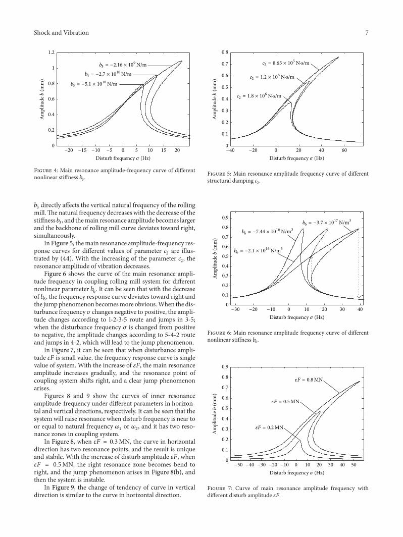

International Journal of
AerospaceEngineeringHindawi Publishing Corporationhttpwwwhindawicom Volume 2014
RoboticsJournal of
Hindawi Publishing Corporationhttpwwwhindawicom Volume 2014
Hindawi Publishing Corporationhttpwwwhindawicom Volume 2014
Active and Passive Electronic Components
Control Scienceand Engineering
Journal of
Hindawi Publishing Corporationhttpwwwhindawicom Volume 2014
International Journal of
RotatingMachinery
Hindawi Publishing Corporationhttpwwwhindawicom Volume 2014
Hindawi Publishing Corporation httpwwwhindawicom
Journal ofEngineeringVolume 2014
Submit your manuscripts athttpwwwhindawicom
VLSI Design
Hindawi Publishing Corporationhttpwwwhindawicom Volume 2014
Hindawi Publishing Corporationhttpwwwhindawicom Volume 2014
Shock and Vibration
Hindawi Publishing Corporationhttpwwwhindawicom Volume 2014
Civil EngineeringAdvances in
Acoustics and VibrationAdvances in
Hindawi Publishing Corporationhttpwwwhindawicom Volume 2014
Hindawi Publishing Corporationhttpwwwhindawicom Volume 2014
Electrical and Computer Engineering
Journal of
Advances inOptoElectronics
Hindawi Publishing Corporation httpwwwhindawicom
Volume 2014
The Scientific World JournalHindawi Publishing Corporation httpwwwhindawicom Volume 2014
SensorsJournal of
Hindawi Publishing Corporationhttpwwwhindawicom Volume 2014
Modelling amp Simulation in EngineeringHindawi Publishing Corporation httpwwwhindawicom Volume 2014
Hindawi Publishing Corporationhttpwwwhindawicom Volume 2014
Chemical EngineeringInternational Journal of Antennas and
Propagation
International Journal of
Hindawi Publishing Corporationhttpwwwhindawicom Volume 2014
Hindawi Publishing Corporationhttpwwwhindawicom Volume 2014
Navigation and Observation
International Journal of
Hindawi Publishing Corporationhttpwwwhindawicom Volume 2014
DistributedSensor Networks
International Journal of