
Requirement Specifications Using Natural Languages -...
81
Requirement Specifications Using Natural Languages Bures, T., Hnetynka, P., Kroha, P., Simko, V. Charles University Faculty of Mathematics and Physics Dep. of Distributed and Dependable Systems Technical Report D3S-TR-2012-05 December 2012
Transcript of Requirement Specifications Using Natural Languages -...

Requirement SpecificationsUsing Natural Languages
Bures, T., Hnetynka, P., Kroha, P., Simko, V.
Charles UniversityFaculty of Mathematics and Physics
Dep. of Distributed and Dependable SystemsTechnical Report D3S-TR-2012-05
December 2012

Contents
1 Introduction 11.1 Introduction to Requirements Engineering . . . . . . . . . . . . . . . 11.2 Why to Use Natural Language in Requirement Engineering . . . . . . 5
2 Natural Language Processing 102.1 Tokens . . . . . . . . . . . . . . . . . . . . . . . . . . . . . . . . . . 102.2 Part-Of-Speech tagging . . . . . . . . . . . . . . . . . . . . . . . . . 102.3 Parsing . . . . . . . . . . . . . . . . . . . . . . . . . . . . . . . . . 112.4 Rule-based natural language processing . . . . . . . . . . . . . . . . 112.5 Statistical natural language processing . . . . . . . . . . . . . . . . . 11
3 Modeling Static Structures from Requirements 12
4 Modeling Dynamic Structures from Requirements 13
5 Constraints 14
6 Using Ontologies 156.1 Ontologies . . . . . . . . . . . . . . . . . . . . . . . . . . . . . . . . 156.2 Terminology of Ontologies . . . . . . . . . . . . . . . . . . . . . . . 166.3 Inference in Ontologies . . . . . . . . . . . . . . . . . . . . . . . . . 16
6.3.1 Why to Use Ontology for Checking Requirements Specifications 176.4 The Idea of Checking Requirements . . . . . . . . . . . . . . . . . . 18
7 Querying to Improve Completeness 21
8 Ontology and the Cyc Platform 22
9 Concepts 24
10 Completeness 25
11 Inconsistency and Contradictions 2611.1 Implementation . . . . . . . . . . . . . . . . . . . . . . . . . . . . . 26
11.1.1 Using ATL for Converting UML to OWL . . . . . . . . . . . 27
1

11.1.2 Using Pellet for Checking Ontology . . . . . . . . . . . . . . 2711.1.3 Using Jess for Reasoning in Ontology . . . . . . . . . . . . . 2711.1.4 Interaction of the used tools . . . . . . . . . . . . . . . . . . 28
11.2 Experiments . . . . . . . . . . . . . . . . . . . . . . . . . . . . . . . 2811.2.1 Checking with rules . . . . . . . . . . . . . . . . . . . . . . 2811.2.2 Checking with restrictions . . . . . . . . . . . . . . . . . . . 30
12 Ambiguity 3212.1 The Syntactic Similarity . . . . . . . . . . . . . . . . . . . . . . . . 3212.2 The Semantic Similarity . . . . . . . . . . . . . . . . . . . . . . . . 33
13 Part-of-Speech Analysis 34
14 Validation of Requirements 3514.1 Validation of Requirements by Text Generation in TESSI . . . . . . . 3514.2 Generate natural language text from UML model . . . . . . . . . . . 36
14.2.1 The approach . . . . . . . . . . . . . . . . . . . . . . . . . . 3814.3 Case study . . . . . . . . . . . . . . . . . . . . . . . . . . . . . . . . 3814.4 Implementation . . . . . . . . . . . . . . . . . . . . . . . . . . . . . 3914.5 Example of the text generated for validation . . . . . . . . . . . . . . 4014.6 Achieved Results and Conclusion . . . . . . . . . . . . . . . . . . . 41
15 Traceability of requirements 42
16 Related Work to Requirements Engineering 4416.1 Related Work to the Concept of Requirements Engineering . . . . . . 4416.2 Related Work to Ontologies in Requirements Specification . . . . . . 4516.3 Related Work to Checking Inconsistency . . . . . . . . . . . . . . . . 4516.4 Related Work to Linguistic Methods . . . . . . . . . . . . . . . . . . 4616.5 Related Work to Requirement Text Generation . . . . . . . . . . . . . 4616.6 The Tool Rational RequisitePro . . . . . . . . . . . . . . . . . . . . . 47
16.6.1 The model used in RequisitePro . . . . . . . . . . . . . . . . 4816.6.2 Traceability in RequisitePro . . . . . . . . . . . . . . . . . . 49
16.7 The Tool RAT . . . . . . . . . . . . . . . . . . . . . . . . . . . . . . 5016.7.1 Controlled Syntax for Writing Requirements . . . . . . . . . 5016.7.2 User-Defined Glossaries and Document Parsing . . . . . . . . 5116.7.3 Classification of problematic phrases . . . . . . . . . . . . . 5216.7.4 Semantic Analysis . . . . . . . . . . . . . . . . . . . . . . . 5216.7.5 Implementation Details and Early User Evaluation of RAT . . 53
16.8 The Tool TESSI . . . . . . . . . . . . . . . . . . . . . . . . . . . . . 5316.8.1 Architecture and Dataflow . . . . . . . . . . . . . . . . . . . 5316.8.2 Natural language analysis in TESSI - using UIMA . . . . . . 5616.8.3 Ontologies in TESSI for Building UML Model . . . . . . . . 5616.8.4 Grammatical Templates for Identification of Parts of UML Model 5816.8.5 Ontologies in TESSI for Checking Consistency . . . . . . . . 5916.8.6 Feedbacks in TESSI . . . . . . . . . . . . . . . . . . . . . . 60
2

17 Open problems 61
3

List of Tables
4

List of Figures
1.1 Use of tools for requirements analysis [100] . . . . . . . . . . . . . . 71.2 Using natural languages in requirement specifications [100] . . . . . . 71.3 Efficiency of software development process [100] . . . . . . . . . . . 8
11.1 Interaction of the used tools . . . . . . . . . . . . . . . . . . . . . . . 29
14.1 Architecture of the text generator component. . . . . . . . . . . . . . 3714.2 Use case diagram. . . . . . . . . . . . . . . . . . . . . . . . . . . . . 3914.3 State machine diagram. . . . . . . . . . . . . . . . . . . . . . . . . . 39
16.1 Natural language processing - overview . . . . . . . . . . . . . . . . 5016.2 Core requirements ontology . . . . . . . . . . . . . . . . . . . . . . 5216.3 Architecture and dataflow of the existing tool TESSI . . . . . . . . . 5416.4 TESSI - Creating and relation between model elements . . . . . . . . 5516.5 UIMA - Aggregated Analysis Engine . . . . . . . . . . . . . . . . . 5716.6 The component for consistency checking . . . . . . . . . . . . . . . . 60
5

Abstract
We discuss the part of the requirement specification process which is located betweenthe textual requirements definition and the semi-formal diagrams of the requirementsspecifications.
It concerns the acquisition and the refinement of requirements, the modeling inUML, and the consensus improvement between the analyst and the user.
We point out open problems in this area that include natural language processing(e.g. automatic construction of UML diagrams from a parsed text of requirements),ontologies, constraints, solution scope and optional requirements, requirement incon-sistency, querying for completness improvement and refinement of requirements, am-biguity, traceability of requirements, and validation feedbacks.

Chapter 1
Introduction
1.1 Introduction to Requirements EngineeringRequirements engineering identifies the purpose and properties of a software system. Itcreats documents in a form that is suitable to analysis, communication, and subsequentimplementation [103]. Traceability of requirements, i.e. links between requirementsand documents of design and implementation, is an important feature for maintenanceof the implemented system.
If a software system has to be built so it has to be described in some way before theanalysis, design, and implementation process will be started. Typically, these descrip-tions (contained in requirement documents) are far from representing the real businesslogic [11]. Instead, we have a set of statements that is:
• incomplete (forgotten features),
• inconsistent (included contradictions),
• ambiguous (more possible interpretations).
During the last twenty years, standards for measuring and certifying effective soft-ware development process have been introduced and popularized. Many books andarticles on software development process have been published. Eventhough, manyquestions remained open:
• How do we explain the high incidence of the software project failure today?
• Why are many, if not most, software projects still plagued by delays, budgetoverruns, and quality problems?
• How can we improve the quality of the systems we build? It is known that ourdaily activities become increasingly dependent on them.
The answers are in the people, tools, and processes applied. Requirements man-agement, more exactly its improvement, is often proposed as a solution to the ongoingproblems of software development.
1

A software requirement can be defined as a condition or capability to which the sys-tem must conform, i.e. as a software capability needed by the user to solve a problemor achieve an objective. It must be met or possessed by the proposed system or sys-tem component to satisfy a contract, specification, standard, or other formally imposeddocumentation [19].
The decision to describe requirements in documents deserves some thought. On theone hand, writing is a widely accepted form of communication and, for most people, anatural thing to do. On the other hand, the goal of the project is to produce a system,not documents. Common sense and experience teach that the decision is not whetherbut how to document requirements.
Document templates provide a consistent format for requirements management.For example, the system Rational RequisitePro offers these templates and the addi-tional feature of linking requirements within a document to a database containing allproject requirements. This unique feature allows requirements to be documented natu-rally, making them more accessible and manageable in a database.
There are many problems occurring in the field of requirements engineering. Thefollowing list gives some of them:
• Requirements are not always obvious and have many sources.
• Requirements are not always easy to express clearly in words.
• Requirements are not always complete.
• Requirements are not always unique.
• Requirements are not always consistent.
• Requirements do not contain all initial solution boundaries and constraints.
• Many different types of requirements at different levels of detail must be man-aged.
• The number of requirements can become unmanageable.
• Requirements are related to one another.
• Requirements are neither equally important nor equally easy to meet.
• Many interested and responsible parties are involved in a project, which meansthat requirements must be managed by cross-functional groups of people.
• Requirements change.
• Requirements can be time-sensitive.
Requirements have many sources. Customers, partners, end users, domain experts,management, project team members, business policies, and regulatory agencies aresome sources of requirements. It is important to know how to determine who thesources should be, how to get access to those sources, and how to elicit information
2

from them. The individuals who serve as primary sources for this information arereferred to as “stakeholders” in the project.
Requirements may be elicited through activities such as interviewing, brainstorm-ing, conceptual prototyping, using questionnaires, and performing competitive analy-sis. The result of requirements elicitation is a list of requests or needs that are describedtextually and graphically and that have been given priority relative to one another.
To define the system means to translate and organize the understanding of stake-holder needs into a meaningful description of the system to be built. Early in systemdefinition, decisions are made on what constitutes a requirement, documentation for-mat, language formality, degree of requirements, request priority and estimated effort,technical and management risks, and scope. Part of this activity may include early pro-totypes and design models directly related to the most important stakeholder requests.A requirement description may be a written document, electronic file, picture, or anyother representation meant to communicate system requirements. The outcome of sys-tem definition is a description of the system that is both natural language and graphical.Some suggested formats for the description are provided in later sections.
The scope of a project is defined by the set of requirements allocated to it. Man-aging project scope to fit the available resources (time, people, and money) is key tomanaging successful projects. Managing scope is a continuous activity that requiresiterative or incremental development, which breaks project scope into smaller, moremanageable pieces.
Using requirement attributes, such as priority, effort, and risk, as the basis for ne-gotiating the inclusion of a requirement is a particularly useful technique for managingscope. Focusing on the requirement attributes rather than the requirements themselveshelps desensitize negotiations that are otherwise contentious.
With an agreed-upon high-level system definition and a fairly well understood ini-tial scope, it is both possible and economical to invest resources in more refined systemdefinitions. Refining the system definition includes two key considerations: develop-ing more detailed descriptions of the high-level system definition and verifying that thesystem will comply with stakeholder needs and behave as described.
The descriptions are often the critical reference materials for project teams. De-scriptions are best done with the audience in mind. A common mistake is to representwhat is complex to build with a complex definition, particularly when the audiencemay be unable or unwilling to invest the critical thinking necessary to gain agreement.This leads to difficulties in explaining the purpose of the system to people both insideand outside the project team. Instead, you may discover the need to produce differentkinds of descriptions for different audiences.
No matter how carefully you define your requirements, they will change. In fact,some requirement change is desirable; it means that your team is engaging your stake-holders. Accommodating changing requirements is a measure of your teams stake-holder sensitivity and operational flexibility, team attributes that contribute to success-ful projects. Change is not the enemyunmanaged change is.
A changed requirement means that more or less time has to be spent on imple-menting a particular feature, and a change to one requirement may affect other require-ments. Managing requirement change includes activities such as establishing a base-line, keeping track of the history of each requirement, determining which dependencies
3

are important to trace, establishing traceable relationships between related items, andmaintaining version control.
A requirement type is simply a class of requirements. The larger and more intricatethe system, the more types of requirements appear. By identifying types of require-ments, teams can organize large numbers of requirements into meaningful and moremanageable groups. Establishing different types of requirements in a project helpsteam members classify requests for changes and communicate more clearly.
Usually, one type of requirement can be broken down, or decomposed, into othertypes. Business rules and vision statements can be types of high-level requirementsfrom which teams derive user needs, features, and product requirement types. Usecases and other forms of modeling drive design requirements that can be decomposedto software requirements and represented in analysis and design models. Test require-ments are derived from the software requirements and decompose to specific test pro-cedures. When there are hundreds, thousands, or even tens of thousands of instances ofrequirements in a given project, classifying requirements into types makes the projectmore manageable.
Unlike other processes, such as testing or application modeling, which can be man-aged within a single business group, requirements management should involve every-one who can contribute their expertise to the development process. It should includepeople who represent the customer and the business expectations. Development man-agers, product administrators, analysts, systems engineers, and even customers shouldparticipate. Requirements teams should also include those who create the system solu-tion engineers, architects, designers, programmers, quality assurance personnel, tech-nical writers, and other technical contributors.
Often, the responsibility for authoring and maintaining a requirement type can beallocated by functional area, further contributing to better large project management.The cross-functional nature of requirements management is one of the more challeng-ing aspects of the discipline.
As implied in the description of requirement types, no single expression of a re-quirement stands alone. Stakeholder requests are related to the product features pro-posed to meet them. Product features are related to individual requirements that specifythe features in terms of functional and nonfunctional behavior. Test cases are relatedto the requirements they verify and validate. Requirements may be dependent on otherrequirements or mutually exclusive.
In order for teams to determine the impact of changes and feel confident that thesystem conforms to expectations, these traceability relationships must be understood,documented, and maintained. Traceability is one of the most difficult concepts to im-plement in requirements management, but it is essential to accommodating change.Establishing clear requirement types and incorporating cross-functional participationcan make traceability easier to implement and maintain.
Both individual requirements and collections of requirements have histories thatbecome meaningful over time. Change is inevitable and desirable to keep pace witha changing environment and evolving technology. Recording the versions of projectrequirements enables team leaders to capture the reasons for changing the project, suchas a new system release. Understanding that a collection of requirements may be as-sociated with a particular version of software allows you to manage change incremen-
4

tally, reducing risk and improving the probability of meeting milestones. As individualrequirements evolve, it is important to understand their history: what changed, why,when, and even by whose authorization.
1.2 Why to Use Natural Language in Requirement En-gineering
To get a contract for a large software project, the software house has to work out afeasibility study and a requirements specification. It is part of the offer to the customerthat additionally includes schedule and price. Its purpose is to describe all features(functional and non-functional) of the new, proposed system that are necessary to beimplemented for the customer to sign the contract.
Requirements are the project team’s to-do list. They define what is needed andfocus the project team. They are the primary method used to communicate the goals ofthe project to everyone on the team.
Requirements define what the stakeholders need and what the system must includeto satisfy the stakeholders’ needs. Requirements are the basis for capturing and com-municating needs, managing expectations, prioritizing and assigning work, verifyingand validating the system (acceptance), and managing the scope of the project.
Requirements may take different forms, including scenarios, unstructured text,structured text, or a combination, and they may be stated at different levels of gran-ularity. At the highest level of granularity, features define the services that the systemmust provide to solve the customer’s problem. These are captured as structured or un-structured text in the project vision. At the next level of granularity, use cases can beused to define the functionality that the system must provide to deliver the requiredfeatures. Use cases describe the sequence of actions performed by the system to yieldan observable result of value.
As mentioned, a system must perform according to the behavior that can be spec-ified as use cases. However, there are system requirements that do not represent aspecific behavior, also known as system-wide requirements, including:
• Legal and regulatory requirements, as well as application standards
• Quality attributes of the system to be built, including usability, reliability, per-formance, and supportability requirements
• Interface requirements to be able to communicate with external systems
• Design constraints, such as those for operating systems and environments andfor compatibility with other software
Formal specification is ideal for the software developer, but it is not reasonable torequire the author of the requirements document, who is seldom familiar with formalmethods or even with the concept of specification, to provide a formal description.State of the art are informal requirements documents written in natural language.
Detailed software requirements should be written in such a form as can be under-stood by both the customers and the development team.
5

Many solutions (e.g., KaOS [89]) require users to write requirements in formalnotations. KaOS presents an approach for using Semantic nets and temporal logic forformal analysis of requirements using a goal based approach. While they can perform abroad range of reasoning, their system needs the requirements to be inputted in a formallanguage. This restriction is not feasible in practice because requirements documentsare written by semi-technical analysts and have to be signed-off by business executives.Hence, the communication medium is still natural language.
We have found that using the language of the customer to describe these softwarerequirements is most effective in gaining the customers understanding and agreement.These detailed software requirements are then used as input for the system design spec-ifications as well as for test plans and procedures needed for implementation and valida-tion. Software requirements should also drive the initial user documentation planningand design.
Using a natural language is necessary because:
• Requirement specification are written by a software house analyst in cooperationwith customer’s experts and potential users. They do very probably not under-stand any more formal specification as a specification in natural language.
• A customer would not sign a contract where requirements specification is writtene.g. only in the Z notation.
Once a contract has been awarded and after a feasibility study has been approved, arequirements specification must be written in more details that describes the propertiesof the new system, i.e. functional properties, non-functional properties, and constraints,in a more detailed way.
Very often, it will be written in some semi-formal graphical representation givenby the CASE tool that is used in the software house.
The role of using natural language in requirement specifications is investigated in[100]. The statistics published in this paper shows that the market was open for morewide use of requirements engineering systems in the year 2003 - see Fig. 1.1. In Fig.1.2 in [100], we can see that the percentual part of requirements described in naturallanguage makes 79 %. In Fig. 1.3 in [100], the need of requirement engineeringautomation is documented.
We can conclude that the use of linguistic techniques and tools may perform acrucial role in providing support for requirements analysis.
It has been found that in a majority of cases it is necessary to use NLP systemscapable of analysing documents in full natural language. If the language used in thedocuments is controlled (giving a subset of natural language), it is possible to use sim-pler and therefore less costly linguistic tools, which in some cases are already available.Instruments of this type can also be used to analyse documents in full natural language,even if in this case more analyst consultation is required to reduce the complexity ofthe language used in input documents or to intervene automatically in the models pro-duced as output. Moreover, needed in many cases, besides an adequate representationof the shared/common knowledge, is specialised knowledge of the domain.
Effective requirements management includes the following project team activities:
6

Figure 1.1: Use of tools for requirements analysis [100]
Figure 1.2: Using natural languages in requirement specifications [100]
• Agree on a common vocabulary for the project.
• Develop a vision of the system that describes the problem to be solved by thesystem, as well as its primary features.
• Elicit stakeholders needs in at least five important areas: functionality,usability,reliability, performance, and supportability.
• Determine what requirement types to use.
• Select attributes and values for each requirement type.
• Choose the formats in which requirements are described.
• Identify team members who will author, contribute to, or simply view one ormore types of requirements.
• Decide what traceability is needed.
• Establish a procedure to propose, review, and resolve changes to requirements.
• Develop a mechanism to track requirement history.
• Create progress and status reports for team members and management.
7

Figure 1.3: Efficiency of software development process [100]
These essential requirements management activities are independent of industry,development methodology, or requirements tools. They are also flexible, enabling ef-fective requirements management in the most rigorous and the most rapid applicationdevelopment environments.
Since software engineers are not specialists in the problem domain, their under-standing of the problem is immensely difficult, especially if routine experiences cannotbe used. It is a known fact [11] that projects completed by the largest software compa-nies implement only about 42 % of the originally-proposed features and functions.
We argue that there is a gap between the requirements specification in a naturallanguage and requirements specification in some semi-formal graphical representation.The analyst’s and the user’s understanding of the problem are usually more or lessdifferent when the project starts. The step from the requirements definition towardsrequirements specification will be done only in the brain of the analyst without beingdocumented.
Usually, the user cannot deeply follow the requirements specification. The first pos-sible time point when the user can validate the analyst’s understanding of the problem,i.e. the first possible feedback, is when a prototype starts to be used and tested.
The phase of natural language requirement specifications pre-processing offers afeedback very soon, before the design and implementation started.
Using an appropriate tool during elicitation of requirements specification in naturallanguage we can check and test requirement specifications during their genesis. Thisis the first feedback possible.
One approach of analyzing requirements is to treat them as a form of pseudo-code,or even a very high-level language, through which the requirements analyst is essen-tially beginning to program the solution envisioned by the stakeholders. In such a case,it would be possible to build tools that analyze requirements, just like compilers ana-lyze software programs. This observation has been shared by a number of researchersin this space and a number of tools have been proposed (comprehensive survey of toolsis available at [8]).
Errors, which arise from incorrect requirements, have become a significant devel-opment problem. Requirements errors are numerous: they typically make up 25 % to70 % of total software errorsUS companies average one requirements error per func-tion point [51]. They can be persistent: twothirds are detected after delivery. They can
8

be expensive. The cost to fix them can be up to a third of the total production cost [5].Moreover, many system failures are attributed to poor requirements analysis [52].
9

Chapter 2
Natural Language Processing
For using natural language processing in requirement specification analysis, it is recom-manded to write sentences of requirements systematically in a consistent fashion start-ing with the agent/actor, followed by an action verb, followed by an observable result.
2.1 TokensThe first step in the natural language analysis is a tokenization. This is a process thatidentifies words and numbers in sentences. It is necessary to specify what is the sen-tence delimiter.
2.2 Part-Of-Speech taggingPart-Of-Speech-Tagging (POS Tagging) is the process of marking up a word in a textas corresponding to a particular part of speech, based on both its definition, as well asits context - i.e. relationship with adjacent and related words in a phrase, sentence, orparagraph. A simplified form of this is commonly taught to school-age children, in theidentification of words as nouns, verbs, adjectives, adverbs, etc.
In computer science, this topic is investigated by computational linguistics. Part-of-speech tagging is harder than just having a list of words and their parts of speech,because some words can represent more than one part of speech at different times,and because some parts of speech are complex or unspoken. This is not rarein naturallanguages (as opposed to many artificial languages), a large percentage of word-formsare ambiguous.
The Penn Treebank Tagset for English [98] contains 36 tags. Currently, the mostpromissing tool we use is Stanford Parser [99].
10

2.3 ParsingParsing is the process that determines the parse tree (grammatical analysis) of a givensentence. The grammar for natural languages is ambiguous and typical sentences havemultiple possible analyses. For a typical sentence there may be very many of potentialparses. Most of them will seem completely nonsensical to a human but it is difficult todecide over their sense algorithmically.
2.4 Rule-based natural language processingPrior implementations of language-processing tasks typically involved the direct handcoding of large sets of rules. It is possible to use methods of machine learning toautomatically learn such rules through the analysis of large corpora of typical real-world examples. A corpus (plural, ”corpora”) is a set of documents that have beenhand-annotated with the correct values to be learned.
The problem is that the rules are ambiguous. We will discuss it more in details inSection 12.
2.5 Statistical natural language processingStatistical natural language processing uses statistical methods to resolve some of thedifficulties discussed above, especially those which arise because longer sentences arehighly ambiguous when processed with realistic grammars, yielding thousands or mil-lions of possible analyses.
Methods for disambiguation often involve the use of corpora and Markov models.The technology for statistical NLP comes mainly from machine learning and data min-ing, both of which are fields of artificial intelligence that involve learning from data.
Textual documents of requirements (use cases, scenarios, user stories, transcrip-tions of conversations for requirements elicitation - often denoted as textual require-ments descriptions) can reach several hundred of pages in large projects. Because ofthat it is useful to process the documents in some related groups obtained by semanticfiltering. It is possible to extract sentences relevant for concept relationships, temporalorganisation, control, causality [28].
11

Chapter 3
Modeling Static Structures fromRequirements
In requirements, parts of UML model can be recognized and identified. It can bedone partially automatically and partially manual. Class diagram (class hierarchy andassociations), attributes, and methods (their existence) are parts of the UML model thatdescribe the static structure.
Their identification can be done automatically with some necessary human interac-tion because of the complexity of real world semantics. The used method is based onthe grammatical inspection [1]. This method offers a judgement saying that nouns insentences of requirement specifications may have a link to classes in the correspondingUML model, verbs may represent methods or relationships, and adjectives may repre-sent a value of an attribute. Because of the natural language complexity, this methodworks satisfactorily only when using a humen interaction.
Some help can be done by applying of part-of-speech tagging analysis, and search-ing for templates in the tree structure that represents the parsed sentence. Some exper-iments we made using TESSI are described in Section 16.8.4.
12

Chapter 4
Modeling Dynamic Structuresfrom Requirements
Parts of UML model that contain sequence diagram (objects, messages), state diagram(states, transitions, events), collaboration diagram, and activity diagram describe thedynamic structures, i.e. the behavior.
The identification of these structures from requirements is more complex.Formalization of textual behavior description can reveal deficiencies in require-
ments documents. Formalization can take two major forms:
• based on interaction sequences (translation of textual scenarios to interactionsequences (Message Sequence Charts, or MSCs) was presented in works [67],[68], [69]),
• based on automata (survey in [66]).
To close the gap and to provide translation techniques for both formalism types,an algorithm translating textual descriptions of automata to automata themselves isnecessary [60].
13

Chapter 5
Constraints
Constraints, which are part of requirements and later parts of the UML model, describerestriction rules of requirements restricting both static structure (e.g. range of attributevalues) and dynamic structure (limits of behavior).
Constraints can be inconsistent. There are many reasons for that, e.g. requirementsare written by many analysts, an analyst cannot recognize that some assertions writtenby himself are contradictory either among each other or to domain assertions.
Constraints are described in OCL (Object Constraint Language) which is strongerthan SWRL (Semantic Web Rule Language) used in Web engineering. As we willdescribe below, description logics have different expresiveness. The reason is that thecomputational complexity of the reasoning, i.e. the computational complexity of thedecision whether the system is correct and consistent, may explode and we never obtainthe result guarenteed if the expressivenes of the used description logic is too high.
The related work is discussed in more details in Section Inconsistency 11 and inSection Related Work to Checking Inconsistency 16.3.
14

Chapter 6
Using Ontologies
6.1 OntologiesAn ontology is a specification of a conceptualization [36]. It makes possible to describea domain including all its concepts with their attributes and relationships. As a standarddescription formalism, the OWL language [144], [145] will be used that is based onRDF (Resource Description Framework) [146], [147], [148], [149].
Additionally to RDF, OWL makes possible to make reasoning by inference ma-chine about elements of ontologies (classes, properties, individuals, relationships).OWL has three variants (sublanguages) that differ in levels of expressiveness. Theseare OWL Lite, OWL DL and OWL Full (ordered by increasing expressiveness). Eachof these sublanguages is a syntactic extension of its simpler predecessor.
OWL Lite was originally intended to support those users primarily needing a clas-sification hierarchy and simple constraints.
OWL DL was designed to provide the maximum expressiveness possible whileretaining computational completeness, decidability (there is an effective procedure todetermine whether an assertion is derivable or not), and the availability of practicalreasoning algorithms. OWL DL is so named due to its correspondence with descriptionlogic, a decidable subset of predicate logic of the first order.
OWL Full is based on a different semantics from OWL Lite or OWL DL, andwas designed to preserve some compatibility with RDF Schema. OWL Full allows anontology to augment the meaning of the pre-defined (RDF or OWL) vocabulary. Itis unlikely that any reasoning software will be able to support complete reasoning forOWL Full.
Description logics (DLs) are a family of logics that are decidable fragments offirst-order logic with attractive and well-understood computational properties. OWLDL and OWL Lite semantics are based on DLs. They combine a syntax for describingand exchanging ontologies, and formal semantics that gives them meaning. Reasoners(i.e. systems which are guaranteed to derive every consequence of the knowledge in anontology) exist for these DLs.
Querying in ontologies is based on querying in RDF-graphes implemented in a
15

query language SPARQL (Simple Protocol and RDF Query Language) [150], [151].
6.2 Terminology of OntologiesLanguages in the OWL family are capable of creating classes, properties, defininginstances and its operations.
A class is a collection of objects. It corresponds to a description logic (DL) concept.A class may contain individuals, instances of the class. A class may have any numberof instances. An instance may belong to none, one or more classes. A class maybe a subclass of another, inheriting characteristics from its parent superclass. Thiscorresponds to logical subsumption and DL concept inclusion notated . All classes aresubclasses of owl: Thing (DL top notated ), the root class. All classes are subclassedby owl: Nothing (DL bottom notated ), the empty class. No instances are members ofowl: Nothing. Modelers use owl: Thing and owl: Nothing to assert facts about all orno instances.
An instance is an object. It corresponds to a description logic individual.A property is a directed binary relation that specifies class characteristics. It corre-
sponds to a description logic role. They are attributes of instances and sometimes actas data values or link to other instances. Properties may possess logical capabilitiessuch as being transitive, symmetric, inverse and functional. Properties may also havedomains and ranges.
Datatype properties are relations between instances of classes and RDF literals orXML schema datatypes.
Object properties are relations between instances of two classes.Languages in the OWL family support various operations on classes such as union,
intersection and complement. They also allow class enumeration, cardinality, and dis-jointness.
6.3 Inference in OntologiesInference in ontologies is based on concepts developed in Description Logic (DL) andframe-based systems and is compatible with RDFS (RDFS is a general-purpose lan-guage for representing simple RDF vocabularies on the Web [112]).
Systems providing inference in ontologies, e.g. OntoSem, use the following knowl-edge resources [80]:
• ontology, a language-independent tangled hierarchy (lattice) of concepts, eachwith a set of properties, representing the theory of the world,
• lexicons for specific natural languages, with most lexical entries anchored in anontological concept, often with the constraints on their properties,
• lexicons for proper names for specific natural languages,
• language-independent text-meaning representation (TMR) language for repre-senting the meaning of a text in ontological terms;
16

• fact repository (FR), the database of recorded TMRs.
The inference process consists of expanding and subsequent matching of TMRmodules corresponding to input-text TMR (TMRI) and query TMR (TMRQ).
6.3.1 Why to Use Ontology for Checking Requirements Specifica-tions
Ontologies seem to be the right tool because they are designed to capture natural lan-guage descriptions of domains of interest. An ontology consists of:
• Description part - a set of concepts (e.g. entities, attributes, processes), theirdefinitions and their inter-relationships. This is referred to as a conceptualiza-tion. Here, ontology represents the domain knowledge (domain ontology) andrequirements can be seen as a specialized subset of it (as problem ontology inour text).
• Reasoning part - a logical theory that constrains the intended models of logicallanguage containing:
– integrity rules of the domain model representing the domain knowledge,
– derivation rules and constraint rules of the problem model.
Reasoning in ontologies brings the inferential capabilities that are not present intaxonomies used for modeling formerly. It makes possible to search for contra-dictions that indicate inconsistencies.
Requirements are based on knowledge of domain experts and users’ needs andwisches. One possible way to classify this knowledge and then fashion it into a tool isthrough ontology engineering.
Ontologies are specifications of a conceptualization in a certain domain. An on-tology seeks to represent basic primitives for modeling a domain of knowledge or dis-course. These primitives are typically concepts, attributes, and relations among conceptinstances. The represented primitives also include information about their meaning andconstraints on their logically consistent application. A domain ontology for guidingrequirements elicitation depicts the representation of knowledge that spans the interac-tions between environmental and software concepts. It can be seen as a model of theenvironment, assumptions, and collaborating agents, within which a specified systemis expected to work. From a requirements elicitation viewpoint, domain ontologies areused to guide the analyst on domain concepts that are appropriate for stating systemrequirements.
Ontologies can be seen as explicit formal specifications of the terms in the domainand relationships among them. They care for a shared understanding of some domainof interest [141]. Such an understanding can serve as the basis for communicationin requirements development. Ontologies are a guarantee of consistency [36] and en-able reasoning. An ontology-based requirements specification tool may help to reduce
17

misunderstanding, missed information, and help to overcome some of the barriers thatmake successful acquisition of requirements so difficult.
Simplified, ontologies are structured vocabularies having possibility of reasoning.It includes definitions of basic concepts in the domain and relations among them. Itis important that the definitions are machine-interpretable and can be processed byalgorithms.
Why would someone want to develop an ontology?Some of the reasons are:
• To share common understanding of the structure of information among peopleor software agents
• To enable reuse of domain knowledge
• To make domain assumptions explicit
• To separate domain knowledge from the operational knowledge
• To analyze domain knowledge
Currently, ontology research has primarily focused more on the act of engineeringontologies or it has been explored more for use in domains other than requirementselicitation, specification, checking, and validation. Other interesting papers in this fieldare [78], [24], [25].
6.4 The Idea of Checking RequirementsIn ontology-based requirements engineering, the correctness, completeness, consis-tency and unambiguity of ontology should be guaranteed so far that it can be usedto guide the requirements elicitation and requirements evolution(!). As we will showbelow, the guarancy is difficult, especially the guarancy of completeness. The require-ments evolution will often be forgotten but the never ending changing of environmentcauses that requirements change and than software systems have to be changed con-stantly. In this context, the traceability of requirements evolution and the traceabilityof requirements implementation is very important.
The goal is not only to develop requirements specification but to create (or to haveavailable) a domain ontology in every project before the requirements specificationprocess will be started. Software houses are usually specialized on producing softwaresystems that solve a specific set of problems, e.g. information systems for financialinstitutions. Therefore the objective is to have an ontology domain available for agiven field of applications and to check requirements of all projects being developedfor this field.
For an ontology being succesfully used in requirements checking, it has to have thefollowing properties: completness, correctness, consistency, and unambiguity.
The intuitive meaning is:
• correctness means that the knowledge in ontology do not violate the rules indomain that correctly represent the reality,
18

• consistency means that there are no contradictory definitions in ontology,
• completeness means that the knowledge in ontology describes all aspects of thedomain,
• unambiguity means that the ontology have defined an unique or unambiguousterminology. There are not obscure definitions of concepts in ontology, i.e. eachentity is denoted by only one, unique name, all names are clearly defined andhave the same meaning for the analyst and all stakeholders.
Correctness and consistency are logical properties that can be checked by somereasoning mechanism under assumption that this mechanism works correctly.
This is what we can use for improving the quality of requirements. After we havechecked the correctness and consistency of the corresponding domain ontology (do-main knowlegde) we can check whether the modeled requirements (transformed intoan ontology) are correct and consistent mutual and correct and consistent to the givendomain ontology.
We cannot be sure that our ontology is complete but we can suppose that it is closeto be complete if it has been used succesfully in many applications. The situation issimilar to the problem of library package verification.
Our goal is to use an ontology in requirements engineering so we have to say whatcompletness of requirements means.Completeness for requiremens means that:
• all categories of requirements (functional and non-functional requirements) areaddressed,
• all responsibilities allocated from higher-level specifications are recognized,
• all use cases, all scenarios, and all states are recognized,
• all assumptions and constraints are documented.
This is a good intuitive definition but it is not constructive. We cannot to use it to decidewhether our requirements are complete.
The problem is in the ”‘all”’, of course. What we can do is to hope that the domainontology is ”‘more complete”’ than the developed requirements so that we can checkthe requirements by comparing them with the ontology and find (perhaps) that thereare some aspects described in the ontology but not described in the requirements.
Ontologies can be used:
• to specify classes and properties of object that should be found in the textualdocuments of requirement specifications [154]
• to check by reasoning in descriptive logics whether the problem ontology spec-ified by requirement specifications is a subset of the domain-specific ontologythat is common for all application in the domain [87]
In [87], we described the last version of TESSI that was constructed to support thefollowing processes:
19

• building a domain ontology in OWL by using Protege (very briefly),
• checking a domain ontology for corretness and consistency by using Racer andJess,
• building a UML model of requirements from textual description of requirements,
• conversion of requirements described as a UML model to a requirements ontol-ogy in OWL and its limits,
• checking requirements tranformed into the requirements ontology for mutuallycorrectness and consistency checking and for checking with respect to the do-main ontology,
• identifying correctness and consistency problems,
• finding the corresponding parts in the former textual description of requirementsand correcting them,
• building a new UML model based on corrected textual description of require-ments,
• after iterations when no ontology conflicts will be found a new textual descrip-tion of requirements will be automatically generated that corresponds to the lastUML model,
• before the UML model will be used for design and implementation the customerand the analyst will read the generated textual description of requirements andlook for missing features or misunderstandings,
• problems found can start the next iteration from the very beginning,
• after no problems have been found the UML model in form of a XMI-file willbe sent to Rational Modeler to further processing.
20

Chapter 7
Querying to ImproveCompleteness
Using domain ontology, there seems to be a possibility to generate some requests au-tomatically that should complete the gaps between knowledge stored in the domainontology and the problem ontology that corresponds to the requirement specifications.Currently, this is an open problem.
The querying supported in the tool Rational RequisitePro makes only possible thatthe analyst can ask for existence and content of a requirement.
21

Chapter 8
Ontology and the Cyc Platform
In practice, some ontologies are available. The possibility should be investigated howto use them in linking ontologies and requirements engineering.
Cyc [13] is the world’s largest and most complete general knowledge base andcommon sense reasoning engine is available.
Cyc can be used as the basis for a wide variety of intelligent applications such as :information extraction and concept tagging, content/knowledge management, busi-
ness intelligence, support of analysis tasks, semantic database integration, natural lan-guage understanding and generation, rapid ontology and taxonomy development, learn-ing and knowledge acquisition, filtering, prioritizing, routing, summarization, and an-notating of electronic communications.
The latest release of Cyc includes:
• 500,000 concepts, forming an ontology in the domain of human consensus real-ity,
• nearly 5,000,000 assertions (facts and rules), using 26,000 relations, that interre-late, constrain, and, in effect, (partially) define the concepts,
• a compiled version of the Cyc Inference Engine and the Cyc Knowledge BaseBrowser,
• natural language parsers and CycL-to-English generation functions,
• a natural language query tool, enabling users to specify powerful, flexible querieswithout the need to understand formal logic or complex knowledge representa-tions,
• an Ontology Exporter that makes it simple to export specified portions of theknowledge base to OWL files,
• documentation and self-paced learning materials to help users achieve a basic- tointermediate-level understanding of the issues of knowledge representation andapplication development using Cyc,
22

• a specification of CycL, the language in which Cyc (and hence ResearchCyc) iswritten (there are CycL-to-Lisp, CycL-to-C, etc. translators),
• a specification of the Cyc API, by calling which a programmer can build anResearchCyc application.
23

Chapter 9
Concepts
Related words may build specific clusters called concepts. The relationship is usuallygiven by similar statistical properties of these words, e.g. their frequency of occurencein one sentence, in one document. It is known from information retrieval and from textmining how to find concepts using term-document matrix and its singular decomposi-tion.
In requirements engineering, we can meet the problem when more people writerequirements and use different vocabulary. Concerning paper is[71].
24

Chapter 10
Completeness
Requirements may be incomplete. This problem is caused by missing some require-ments of a certain type. For example, it is often the case that performance requirementsfor a system are omitted either due to the lack of knowledge among the stakeholders orbecause the requirements analysts fail to elicit them.
This leaves the technical designers and developers to make design choices aboutthe software system, which may or may not meet the stakeholders approval.
Another case is that some system features are not mentioned by the stakeholdersbecause they think everybody knows them including the analyst. Often, it is not thecase and the analyst works having incomplete requirements. Concerning paper is [75].
25

Chapter 11
Inconsistency andContradictions
Requirements may be inconsistent which means that they are either conflicting witheach other or with some policy or business rule (contained e.g. in domain rules, indomain ontology). Because of that terms should be used consistently and as defined inthe glossary. Different phrases or words should not refer to the same thing [73], [108].
In [86], [87], we investigated how the methods developed for using in SemanticWeb technology could be used in validating of requirements specifications. The goalof our investigation was to do some (at least partial) checking and validation of theUML model using a predefined domain-specific ontology in OWL, and to process somechecking using the assertions in descriptive logic.
We argue that the feedback caused by the UML model checked by ontologies andOWL DL reasoning has an important impact on the quality of the outgoing require-ments.
The paper [87] describes not only methods but also implementation of our toolTESSI (in Protege, Pellet, Jess) and practical experiments in consistency checking ofrequirements.
11.1 ImplementationAs we already mentioned above we needed to implement:
• converting UML model into problem ontology model,
• checking ontology class hierarchy,
• checking consistency of ontology rules.
The component of TESSI containing the ontology-based consistency checking ofrequirements specification has been implemented in [44].
26
11.1.1 Using ATL for Converting UML to OWLOur goal was to convert the UML model obtained from the textual requirements intoa corresponding problem ontology model that can be compared with the domain on-tology model. The comparison results in consideration whether some new knowledgeconcerning the correctness, consistency, completness, and unambiguity could be made.
There are some tools available. The UMLtoOWL tool by Gasevic [?] convertsUML model description in extended Ontology UML Profile (OUP) using the XMLMetadata Interchange (XMI) format to The Web Ontology Language (OWL) ontolo-gies. The tool is implemented using eXtensible Stylesheet Language Transformation(XSLT).
We have used the Eclipse Framework and the ATL Use Case UML2OWL by Hillairet[38]. He implemented a transformation according to the ODM specification. It con-sists of two separate ATL transformations. The first transformation UML2OWL takesan UML model as input and produces an ontology as OWL metamodel. The secondtransformation is an XML extractor that generates an XML document according to theOWL/XML specification by the W3C. We have extended Hillairets scripts to fit theUML models of TESSI and added support for SWRL contraints. These constraints areconverted to SWRL/XML syntax to fit inside the OWL. This is done by an ANTRLparser and compiler that can convert SWRL rules in informal syntax entered in TESSIinto the correct OWL/SWRL syntax. The use of SWRL rules provides us further posi-bilities for checking our model.
11.1.2 Using Pellet for Checking OntologyPellet is a tool that allows ontology debugging in the sense that it indicates the rela-tion between unsatisfiable concepts or axioms that cause an inconsistency. We use it tocheck whether the requirements problem ontology subsumes the domain ontology. Be-cause our problem ontology is generated from the UML model by the convertor ATL,there are no problems to be expected in the structure of the problem ontology becausethe UML model has been built under respecting rules for well-formed UML model.
The OWL files generated in the previous step can be loaded into Protege. Fromthere they can be transferred to a reasoner using the DIG description logic reasoner in-terface. The DIG interface is an emerging standard for providing access to description-logic reasoning via an HTTP-based interface to a separate reasoning process. Currentreleases of Protege already include the Pellet reasoner, since it is robust and scalable,and is availabl under an open-source license.
11.1.3 Using Jess for Reasoning in OntologyTo find inconsistencies in ontology rules we need an inference machine. We usedthe Jess rule engine [23]. Jess was inspired by the CLIPS expert shell system andadds additional access to all the powerful Java APIs for networking, graphics, databaseaccess, and so on. Jess can be used free of charge for educational purposes. BecauseProtege and Jess are implemented in Java, we can run them together in a single Java
27

virtual machine. This approach lets us use Jess as an interactive tool for manipulatingProtege ontologies and knowledge bases.
Protege offers two ways to communicate with Jess. The first one is the pluginJessTab, which provides access to the Jess console and supports manual mapping ofOWL facts into Jess and back. We used the second plugin SWRLTab. It is a develop-ment envirionment for SWRL rules in Protege and supports automatical conversion ofrules, classes, properties and individuals to Jess. From there you can control the Jessconsole and look up the outputs. This is done by a plugin for SWRLTab called SWRL-JessTab, which contains a SWRL to Jess bridge and a Jess to Java bridge. This allowsthe user to add additonal functions to their SWRL rules by defining the correspondingfunctions as Java code and use them inside Protege. SWRLTab lets you also insert theinferred axioms back into your ontology. This way it is possible to use complex rulesto infer new knowledge.
11.1.4 Interaction of the used toolsAll these described tools are put together during the requirement analysis. Figure 11.1shows how this is done. Starting with the textual description and an ontology describingthe domain the analyst can use TESSI to create a model of the planned system. Thismodel can also contain constraints which will be compiled into SWRL rules by anANTLR parser. The rest of the model will be transformed into an UML model [152],which will later be converted into an ontology. The ontology is merged with the SWRLrules and can then be opened in Protege. From there the analyst can check the modelconsistency with Pellet and validate the rules with SWRLTab and Jess. The knowledgegained will then be used to make corrections to the TESSI model.
11.2 ExperimentsFor experiments, we used a requirements specification of a library [87]. The text de-scribes fictional requirements for a library management system. It contains aspects ofmedia and user management, describing several special use cases and state machinesfor selected classes. The text was developed to show the posibilities TESSI providesfor requirement analysis.
11.2.1 Checking with rulesAs an example of checking rules, we have the following case. There is a relation”borrow” between Librarian and User. But if we model Librarian as a subset of classUser, because a librarian may also borrow books, the Librarian (as an instance) couldborrow a book himself. This is not what we want. Usually, we do not allow that aclerk in a bank can give a loan to himself, we do not want that a manager decides abouthis salary etc. The solution is that we do not allow some relations to be reflexive inthe domain ontology, e.g. the relation ”borrow”. Any problem ontology that does notcontain the condition that a librarian must not borrow a book to himself will be foundto be inconsistent to the domain ontology.
28

Protégé
TESSI
requirementsdescription
domainontology
UML model
requirementsmodel constraints
ontology of requirements SWRL rules
ANTLRparser
ATLtransformation
transformation
consistentrequirements
consistentrules
JessPellet
Figure 11.1: Interaction of the used tools
29

This example can be checked in TESSI by modelling the two classes User andLibrarian. We decide that a Librarian is a specialization of an User with addional pos-sibilities to manage the library. Then we define an association between these two andname the direction from Librarian to User borrowsTo. After that we can use SWRL-Rules to describe the desired behavior. The first rule we need will set the relationbetween every possible Librarian and User pair:
Librarian(?x)∧User(?y)→ borrowsTo(?x,?y)
The second rule will be used to check if any of the librarians is able to borrow a bookto himself:
borrowsTo(?x,?y)∧ sameAs(?x,?y)→ error(?x,”self”)
Now we can create an UML model based on our example and then generate an ontolo-gie with this content. The ontology will then be loaded into Protege.
The Protege plugin SWRLTab offers several ways to work with SWRL rules. Italso allows us to communicate with the Jess rule engine. Using this plugin we cantransform the knowledge of the ontology in facts for Jess. Running Jess will then causenew facts to be inferred.
In our case it will set up the borrowsTo relationship for all Users and Librariansand then test for Librarians that borrow to theirselves. The Inferred Axioms windowin Protege will then list all possible errors and we can use this information to makecorrenctions to the model in TESSI. In this case we can remove the subclass from Userand after a further test Jess will get no errors.
11.2.2 Checking with restrictionsA second example will show the posibility to check restrictions. In our library a usercan borrow books or reserve them if they are not available. In order to limit users to afixed amount of reservations the reserve relation should be restricted.
In TESSI these conditions can be modeled with associations. Therefor we use theartifact dialog for associations to create a new Instance at the corresponding positionin the requirements text. We set User and MediumInstance as association ends. Thedirection from User to MediumInstance will be labeled with reservedMedia an gets thecardinality 0 to n, in this example n is set to 3. Both classes User and MediumInstancemust have set some equivalents in the domain ontology to access the correspondingindividuals later. To provide some test data we need to add a constraint that fills thereservedMedia relation:
User(?x)∧MediaInstance(?y)→ reservedMedia(?x,?y)
After converting the model to UML and to an ontology we use the SWRLTab to inferthe new axioms and then use the Jess to OWL button to include the new knowledge intoour ontology. Afterwards we can check the results on the individuals tab in Protege. Itwill show red borders around properties which do not meet the defined restrictions.
Based on these observations either the restrictions must be corrected or the test datais wrong and the constraint for filling it must be adopted.
30

One of the problems that may occur is that the restriction rules of requirements(called constraints) are described in OCL (Object Constraint Language) which is strongerthan SWRL. As we will describe below description logics have different expresiveness.The reason is that the computational complexity of the reasoning, i.e. of the decisionwhether the system is correct and consistent, may explode and we never obtain theresult guarenteed if the expressivenes of the used description logic is too high.
An other problem is the necessarily use of individuals to process SWRL rules. Thisrequires to add several individuals of every class the the domain ontology whithoutknowing what rules will later be modeled in TESSI. It also requires to have somemeaningful properties set to these objects. Otherwise it will not be possible to validatethe model with SWRL rules.
SWRL also offers only limited possibilities to express rules. The formulas arebased on first oder logic but can only contain conjunctions of atomic formulas. There isno support for quantiviers or more complex terms. SWRL also can’t express negations,which requires the user to create formulas on a special way and limits the expressive-ness of SWRL rules.
Ontology research has primarily focused on the act of engineering ontologies orit has been explored for use in domains other than requirements elicitation, specifica-tion, checking, and validation. Using ontologies supports consistency which is criticalto the requirements engineering process. Consistent understanding of the domain ofdiscourse reduces ambiguity and lessens the impact of contextual differences betweenparticipants.
31

Chapter 12
Ambiguity
Text information usually enables more than one interpretation. To find the one correctinterpretation that should be programmed we use the context and interaction with thecustomer or domain expert. This is very problematic for automatic systems, of course[70], [32], [7], [54]. To describe ambiguity we distinguish syntactic similarity andsematic similarity of words.
12.1 The Syntactic SimilarityUsually, when people talk about the similarity of words, they mean semantic similarity(e.g. synonomy). However, it is also useful to think about the syntactic similarityof words, i.e. how similar are two words with respect to their syntactic function orrole? You can think of traditional part-of-speech tags as a coarse theory of syntacticsimilarity, e.g. all personal pronouns have similar syntactic roles. Still, it would be niceto have a quantitative measure of the exact degree of syntactic similarity between twowords.
The method explored in [35] (and a similar method described in [125]) proposes tocompute syntactic similarity as the cosine distance between the syntactic behavior ofwords represented as normalized feature vectors of the frequency of unique parse treepaths in large corpora of syntactically parsed text.
The syntactic similarity will be used in solving the plagiarism problem. The prob-lem of detecting web documents that have some similarity degree with a given inputdocument is very important. Search engines avoid indexing similar documents in theirdocument bases, people wish to find documents that originated an input text, or evendetect plagiarism between several documents obtained from the Web, among others[107].
The syntactic ambiguity is given by ambiguity of the language structure. In [41],the following example is given: The cop saw the robber with the binoculars. This sen-tence could mean either the cop was using the binoculars, or the robber had binoculars.In these cases, the discourse level of information is needed.
The disadvantage of syntactic similarity is that two sentences having the same
32

words in different order can have a high syntactic similarity but a completely differentmeaning. Because of that semantic similarity will be used even though the syntacticsimilarity can be easier computed and in many cases can bring good results.
12.2 The Semantic SimilarityDetermining semantic similarity of two sets of words that describe two entities is animportant problem in web mining (search and recommendation systems), targeted ad-vertisement and domains that need semantic content matching [138]. Usually, the con-tent of documents is represented using the model ”bag of words”. This causes thatrelationships that are not explicit in the representations are usually ignored. Further-more, these mechanisms cannot handle entity descriptions that are at different levels ofgranularity or abstractions as the implicit relationship between the concepts is ignored.
To define semantics of a word the same words of two sentences have to be comparedincluded their context.
In [95], an algorithm is given that can solve this problem for English and fordatabase WordNet4. After the semantics of words in both sentences will be specified,the sematic similarity can be calculated based on distance metrics [131], [4].
33

Chapter 13
Part-of-Speech Analysis
A Part-Of-Speech Tagger (POS Tagger) is a piece of software that reads text in somelanguage and assigns parts of speech to each word (and other token), such as noun,verb, adjective, etc., although generally computational applications use more fine-grained POS tags like ’noun-plural’. Concerning papers are [72], [74], [75].
There is a successful Stanford Log-linear Part-Of-Speech Tagger [139], [140]. Sev-eral downloads are available. The basic download contains two trained tagger modelsfor English. The full download contains three trained English tagger models, an Ara-bic tagger model, a Chinese tagger model, and a German tagger model. Both versionsinclude the same source and other required files. The tagger can be retrained on anylanguage, given POS-annotated training text for the language. The English taggers usethe Penn Treebank tag set.
Another successful tagger is the Tree Tagger form University of Stuttgart [127],[128] that is fre available, too.
34

Chapter 14
Validation of Requirements
The validation process will be explained usually im context of a verification process.The verification process means that software product properties are checked against itsspecification. After a successfully finished verification, we can say that the product isconform to its specification. The problem is that the specification may be incomplete.So, the validation process specifies how the customer is satisfied [64].
14.1 Validation of Requirements by Text Generation inTESSI
In this section, we describe our approach to textual feedback in requirement specifica-tion that we developed and published in more details in [88].
UML model is used for the synthesis of a text that describes the analyst’s under-standing of the problem, i.e. a new, model-derived requirements description will auto-matically be generated. Now, the user has a good chance to read it, understand it andvalidate it. His/her clarifying comments will be used by the analyst for a new versionof the requirements description. The process is repeated until there is a consensus be-tween the analyst and the user. This does not mean that the requirements description isperfect, but some mistakes and misunderstandings are removed.
We argue that the textual requirements description and its preprocessing by ourtool will positively impact the quality and the costs of the developed software systemsbecause it inserts additional feedbacks into the development process.
This document represents the analyst’s understanding of the problem. It is verylikely that the analyst and the user understand some words (some concepts) differently,it is very likely that the user holds some facts for self-evident and thinks they are notworth being mentioned. It is also very likely that some requirements have been forgot-ten. The document is a starting point to the next analysis. Using our tool TESSI theanalyst identifies classes, methods, and attributes in the way how he/she understandsthe textual requirements and stores them into a UML-model. Our new approach is thatfrom this UML-model a text can be generated that reflects how the analyst modeled theproblem. The generated text is given to the user.
35

The user does not understand the UML-model but he/she can read the text gener-ated and can decide whether it corresponds to his/her wishes. He/she discussed it withthe analyst and the next iteration of the process of requirements refinement starts. Ad-ditionally, our tool can generate some simple questions, e.g. concerning constrains ofattributes. These questions can influence the next iteration text, too.
After some iterations, when the user and the analyst can not find any disproportions,the last UML-model will be exported to the next processing. We use an interface toRational Software Modeler (IBM). This tool produces diagrams of any kind, fragmentsof code in different programming languages, etc. The fragments of code have to befurther completed and developed to a prototype. The prototype will be validated by theuser and his/her comments will be inserted into the textual description of requirements.
As we can see our approach means that we use one additional feedback during themodeling before an executable prototype is available. It is very well known that themistakes from requirements are very expensive because:
• it is expensive to find them because the costs grow up in exponential proportionto the distance between the time point when the mistake occured and the timepoint when the mistake was corrected,
• it is very likely that parts of the design and programming efford have been in-vested in vain and these parts have not only to be corrected but they have to bedeveloped again.
The implemented component for text generation is a part of our CASE tool. Asmentioned above, in the first phase of requirements acquisition, a text containing knowl-edge about the features of the system to be developed, is written in cooperation betweenthe analysts, domain experts, and users. The analyst processes this text and, using theMODEL component, decides which parts of the text can be associated to which partsof the UML model. Then the GENERATOR component generates a text correspondingto the UML model and the user validates it. This process can iterate (see Fig. 16.3)until the differences disappear.
14.2 Generate natural language text from UML modelFor the purpose of paraphrasing the specified UML model for users and domain ex-perts, an NL text is generated from the UML model.
Differently from works that use templates completed with informationfrom as-signed isolated model elements our linguistic approach can collect and combine piecesof information from the whole model for using them together in sentences of the gen-erated text.
For the component GENERATOR we used the standard pipeline architecture [114]for NL generation, extended by an additional module used for NL analysis tasks [18].Three modules are arranged in a pipeline where each module is responsible for oneof the three typical NL generation subtasks, which include, in this order, documentplanning, micro planning and surface realization (Fig. 14.1). The output of one moduleserves as input for the next one.
36

Figure 14.1: Architecture of the text generator component.
The input to the document planner is a communicative goal which is to be fulfilledby a text generation process. The communicative goal is basis for the selection ofinformation (content determination) from a knowledge base.
In our case, the goal is to validate a requirements model and the knowledge base isthe model itself.
Output of the document planner is:
• a document plan,
• a tree structure with message nodes,
• structural nodes.
Message nodes store pieces of information (NL text fragments) to be expressed ina sentence, structural nodes indicate the composition of the text and the order in whichthe sentences must occur.
The micro planner accepts a document plan as its input and transforms it into amicro plan by processing message nodes. Sentence specifications are produced, whichcan be either strings or abstract representations describing the underlying syntacticstructure of a single sentence. In the latter case, this is done by a complex process(as described below) involving the tasks of NL parsing, linguistic representation andaggregation of text fragments as well as choosing additional lexems and referring ex-pressions (articles).
37

A micro plan is transformed into the actual text (surface text) of a certain targetlanguage by a surface realizer. During structural realization the output format of thetext is developed. The process of linguistic realization performs the verbalization ofabstract syntactic structures by determining word order, adding function words andadapting the morphological features of lexems (e.g. endings).
14.2.1 The approachFirst, we wrote the presupposed text that should be generated in our case study usingsemantic relations between its parts, which can be derived from the UML model. Thereare semantic relations in UML models between the following elements:
• use case and sequence diagram
• class and state machine
• use case and transition in a state machine
Examples are given in Section 14.3.After this, we analyzed possibilities to derive the target text from an existing UML
model. We found that there are:
• fixed text fragments that specify the structure of the generated text
• directly derivable text fragments that can be copied, e.g. names of classes
• indirectly derivable text fragments that depend on syntax and morphology rules
• not derivable text fragments that cannot be derived from the model
We noticed that a minor part of the text could be produced by a simple template-based approach. This is the case for sentences combining fixed text fragments anddirectly derivable text fragments.
To simplify the generation process where possible we made our text generator ca-pable to perform template-based generation as well. However, a generation based ontemplates was not sufficient for the major part of the text. In cases where sentences con-tain indirectly derivable text fragments, a method depending on linguistic knowledgewas needed.
14.3 Case studyTo illustrate our text generation method, we now apply it to a contrived specification ofa library automation system.
As an example, we combine information from use case diagrams and state machinediagrams in the following way:
• Use case diagram ... “borrow instance”
• State machine diagram ... “available”, “available and reserved”
38

Figure 14.2: Use case diagram.
Figure 14.3: State machine diagram.
• Generated text: “Only instances can be borrowed which are available, or avail-able and reserved and the user is the first on the reservation list”.
“If the instance is signed as available the user can borrow the instance. Theinstance will afterwards be signed as borrowed. Alternatively, if the instance issigned as available and reserved and the user is on the reservation list the usercan borrow the instance. The instance will afterwards be signed as borrowed.”
14.4 ImplementationThe current system is a Java/Eclipse application. The NL generation component hasbeen developed as a module and integrated into the system as a plug-in component.
The generator produces output texts in the English language. The results of the dif-ferent generation steps (document plan, micro plan, output text) are represented usingXML technology.
The task of document planning is managed by schemata, each of them is respon-sible for the generation of a certain part of the document plan. To fulfill the com-municative goal Describe Dynamic Model several schemata exist which specify theinterwoven steps of content determination and document structuring.
According to the two main subtasks the micro planner performs, the module in-cludes a ProtoSentenceSpecBuilder and a SentenceSpecBuilder. The ProtoSentence-SpecBuilder processes an input message and produces a proto sentence specification.
39

After that, the SentenceSpecBuilder transforms the proto sentence specification into asentence specification. The SentenceSpecBuilder provides an interface that is realizedby several components according to the different types a proto sentence specificationmay have. Thus, the individual implementations encapsulate the complete knowledgeneeded for the creation of the DSyntS of a specific sentence type from data stored inthe proto sentence specification.
For NL analysis the Stanford parser [58], [59] is used. This parser provides twodifferent parsing strategies (lexicalized factored-model, unlexicalized PCFG) that bothcan be chosen for the task of preprocessing (micro planning). Access to the parserand corresponding components used for the processing of dependency structures andDSyntS is granted by the interface the AnalysisSystem provides.
Our generator component produces output texts formatted in XHTML. The markup is developed in the stage of structural realization performed by the XHTMLRealiser.To accomplish linguistic realization and produce the surface form of the output textsRealPro [113] is used.
14.5 Example of the text generated for validationAs an example, we show a fragment of a generated text that is a part of a generatedLibrary system description, i.e. the text is generated from UML-model of a Librarysystem. In the following there is the description of the function BorrowInstance:
BorrowInstanceThis function can be done by a user.
Preconditions and effects:If the instance is signed as available the user can borrow the instance. The instance
will afterwards be signed as borrowed. Alternatively, if the instance is signed as avail-able and reserved and the user is on the reservation list the user can borrow the instance.The instance will afterwards be signed as borrowed.
Procedure:
1. The user identifies himself.
2. The user specifies the instance by the shelfmark.
3. A component (User Administration part of the Library system) registers the in-stance in the borrowed-list of the user account.
4. A component (Media Administration part of the Library system) registers theuser in the borrowed-list of the instance.
40

5. A component (Media Administration part of the Library system) changes thestatus of the instance.
6. A component (Media Administration part of the Library system) returns the re-ceipt.
14.6 Achieved Results and ConclusionA component has been designed and implemented in [88] which serves as an impor-tant basis for sophisticated NL text generation with the purpose of validating require-ments analysis models. The text generator performs text generation in three consecu-tive steps: document planning, micro planning and surface realization. It presents anapproach to text generation based on textual input data using NL-analysis- and NL-generation-techniques. Compared to texts produced by the pre-existing template-basedtext generator, texts generated by the new non-trivial text generator are definitely morestructured, more clearly arranged and more readable.
Further, the vocabulary used should be more understandable for people outside thesoftware industry. As far as it has been considered possible, generated texts do notcontain terms specific to software engineering. Due to the usage of RealPro for surfacerealization, the grammar of generated sentences is also more correct than before.
Currently, the text generator is capable of producing NL texts from use cases, se-quence diagrams and state machines. As the architecture has been designed with theaim of easy extensibility, it should not be too difficult to integrate text generation func-tionality for other UML model elements as well. Furthermore, it is possible to adaptthe text generator to other target languages.
A number of open issues may be addressed in the future: prevention of generationerrors caused by the NL parser, improvement of the micro planner, integration of textschemata for other model elements (such as static structures like classes).
Further it is desirable to evaluate our proposed validation approach by applicationto real-world projects. This is not easy because it is necessary to persuade the manage-ment in a software house to run a project in two teams (one team should use our tool)and then to compare the results.
41

Chapter 15
Traceability of requirements
Traceability of requirements means that for any change in a requirement all its impactscan be found. There are impacts in other requirements, there are impacts in design,implementation, and test cases [133].
In software evolution and adaptive maintenance, traceability of requirements is veryimportant. When we move from analysis to design, we assign requirements to the de-sign elements that will satisfy them. When we test and integrate code, our concern iswith traceability to determine which requirements led to each piece of code. The toolTESSI builds and maintains some important relationships between requirements andparts of the resulted system, e.g. bi-directional links between the identified entities insentences of textual requirements and the corresponding entities of the model. Theselinks will be followed during an adaptive maintenance. This helps to hold requirementsand programs consistent and supports the concept of software evolution in which ev-ery change in the software system should start with the change of the requirementsspecification and follow the life-cycle of development.
Requirements traceability paths:
• Trace top level requirements into detailed requirements
• Trace requirements into design
• Trace requirements into test procedures
• Trace requirements into user documentation plan
Traceability links requirements to related requirements of same or different types.RequisitePros traceability feature makes it easy to track changes to a requirementthroughout the development cycle. Without traceability, each change would requirea review of your documents to determine which, if any, elements need updating.
If either end-point of the connection is changed, the relationship becomes suspect.If you modify the text or selected attributes of a requirement that is traced to or tracedfrom another requirement, RequisitePro marks the relationship between the two re-quirements suspect.
42

Traceability relationships cannot have circular references. For instance, a traceabil-ity relationship cannot exist between a requirement and itself, nor can a relationshipindirectly lead back to a previously traced from node. RequisitePro runs a check forcircular references each time you establish a traceability relationship.
The trace to/trace from state represents a bidirectional dependency relationship be-tween two requirements. The trace to/trace from state is displayed in a TraceabilityMatrix or Traceability Tree when you create a relationship between two requirements.
Traceability relationships may be either direct or indirect. In a direct traceabilityrelationship, a requirement is physically traced to or from another requirement. Forexample, if Requirement A is traced to Requirement B, and Requirement B is tracedto Requirement C, then the relationships between Requirements A and B and betweenRequirements B and C are direct relationships.The relationship between RequirementsA and C is indirect. Indirect relationships are maintained by RequisitePro; you cannotmodify them directly. Direct and indirect traceability relationships are depicted witharrows in traceability views. Direct relationships are presented as solid arrows, andindirect relationships are dotted and lighter in color.
A hierarchical relationship or a traceability relationship between requirements be-comes suspect if RequisitePro detects that a requirement has been modified. If a re-quirement is modified, all its immediate children and all direct relationships traced toand from it are suspect. When you make a change to a requirement, the suspect stateis displayed in a Traceability Matrix or a Traceability Tree. Changes include modifica-tions to the requirement name, requirement text, requirement type, or attributes.
43

Chapter 16
Related Work to RequirementsEngineering
Many books (e.g. [118], [90], [110]) and many articles on software development pro-cess have been published. In [15], they found 5,198 publications about requirementengineering spanning the years from 1963 through 2008.
16.1 Related Work to the Concept of Requirements En-gineering
To obtain semantic information directly from a text, manual or automatic methodscan be used. Many papers and books [10] support manual methods. For example,the method of grammatical inspection of a text can be mentioned. It analyzes thenarrative text of use cases, identifies and classifies the participating objects [43]. Inthis method, nouns will be held for candidates for objects or classes, adjectives will beheld for candidates for attributes, and verbs will be held for candidates for methods orrelationships. The Object Behaviour Analysis [119] belongs to this group of methods,too.
There are some tools helping in requirements management (DOORS, RequisitePro 16.6) that transform unstructured texts of requirements into structured texts. Theyneither build any models nor generate refining questions like our tool TESSI.
Automatically generated natural-language description of software models that isthe main contribution of the tool TESSI is not a new idea. The first system of this kindwas described in [134]. More recent projects include the ARIES [50] and the GEMAdata-flow diagram describer [129].
Even if it is widely believed that the graphical representation is the best base for thecommunication between the analyst and the user, there are some serious doubts aboutit. It has been found in [56] that even a co-operation between experienced analysts andsophisticated users who are not familiar with the particular graphical language (whichis very often the case) results in semantic error rates of about 25 % for entities and
44

70 % for relations. Similar results brings [109]. Some systems have been built whichtransform diagrams, e.g. ER-diagrams, into the form of a fluent English text. Forexample, a system MODEX has been described in [91], [92] which can be used for thispurpose. Differently to our system, input to MODEX (MODel EXplainer) is based onthe ODL standard from the ODMG group.
The first version of our system TESSI has been introduced in [83]. Additionally toMODEX, it supports the manual analysis of the requirements description by the analystand the semi-automatic building of an OO-model in UML. Differently from MODEX,we have used simpler templates for generating the output text, because our focus wasnot in linguistics. The current version of TESSI generates refining questions and usesan XML-interface to Rational Rose.
16.2 Related Work to Ontologies in Requirements Spec-ification
There are a number of research approaches to elicit and analyze domain requirementsbased on existing domain ontologies. For example, [93] used a domain ontology and re-quirements meta-model to elicit and define textual requirements. The system GOOREproposed in [130] represents an approach to goal-oriented and ontology-driven require-ments elicitation. GOORE represents the knowledge of a specific domain as an ontol-ogy and uses this ontology for goal-oriented requirements analysis [66]. A shortcomingof these approaches is the need for a pre-existing ontology, as to our knowledge thereis no suitable method for building this ontology for requirements elicitation in the firstplace in an at least semi-automated way.
16.3 Related Work to Checking InconsistencyUsing ontologies to shape the requirements engineering process is clearly not a newidea. In the area of knowledge engineering, ontology was first defined by [101].
An ontology-based approach to knowledge acquisition from text through the useof natural language recognition is discussed in [8], [48], in [53] and the last approachin [9]. In [141] they have constructed the Enterprise Ontology to aid developers intaking an enterprise-wide view of an organisation. The approach in [49] is intended toautomate both interactions with users and the development of application models.
The ontologies used by [122] in their Oz system are domain models which pre-scribe detailed hierarchies of domain objects and relationships between them. Formalmodels for ontology in requirements are described in [46]. Domain rules checking isdescribed in [96]. In [156] the inconsistency measurement is discussed. The ontol-ogy used by the QARCC system [6] is a decomposition taxonomy of software systemquality attributes. QUARCC uses a specialized model for identifying conflicts betweenquality (non-functional) requirements. QuARS [34] presents an approach for phrasalanalysis and classification of natural language requirements documents.
In [96] a formal model of requirements elecitation is discused that contains domainontology checking.
45

Concerning inconsistencies the overview is given in [22], in [102], and lately in[132] but there is not an approach applying ontology in the sense of our way.
However, our work is not specifically addressing the issue of improving natural lan-guage communication between stakeholders in an interview in order to achieve morepolished requirements as most of the related papers are. We investigate the possibilityof combining UML model and OWL ontology for checking and validating require-ments specifications, as we have already mentioned above.
16.4 Related Work to Linguistic MethodsIn [57], three experiments are presented concerning domain class modeling. The toolused for the experiment named NL-OOPS extracts classes and associations from aknowledge base realized by a deep semantic analysis of a sample text.
In [142], a tool is introduced, called the Requirements Analysis Tool (RAT) that au-tomatically performs a wide range of syntactic and semantic analyses on requirementsdocuments based on industry best practices, while allowing the user to write these doc-uments in natural language. RAT encourages users to write in a standardized syntax,a best practice, which results in requirements documents that are easier to read andunderstand. RAT performs a syntactic analysis by using a set of glossaries to identifysyntactic constituents and flag problematic phrases. An experimental version of RATalso performs semantic analysis using domain ontologies and structured content ex-tracted from requirements documents during syntactic analysis. The semantic analysis,which uses semantic Web technologies, detects conflicts, gaps, and interdependenciesbetween different sections (corresponding to different subsystems and modules withinan overall software system) in a requirements document.
16.5 Related Work to Requirement Text GenerationAutomatically generated texts can be used for many purposes, e.g. error messages,help systems, weather forecast, technical documentation, etc. An overview is given in[106].
In most systems, text generation is based on templates corresponding to modelelements (discussed in [16]). There are rules on how to select and instantiate templatesaccording to the type and contents of an element of the model. String processing isused as a main method. We used it in the first version of our system and found thattexts generated in this way were very large and boring.
Another disadvantage was that the texts we generated were often not right in thesense of grammar [83]. Building all possible grammatical forms for all possible instan-tiations had been too complex [40], [20]. Further, the terminology used in the generatedtexts also included specific terms from the software engineering domain, which reducestext understandability for users and domain experts. The maintenance and evolution ofsuch templates was not easy.
Except for our previous work [84], [117], there are at least two similar approacheswith the aim of generating natural language (NL) text from conceptual models in order
46
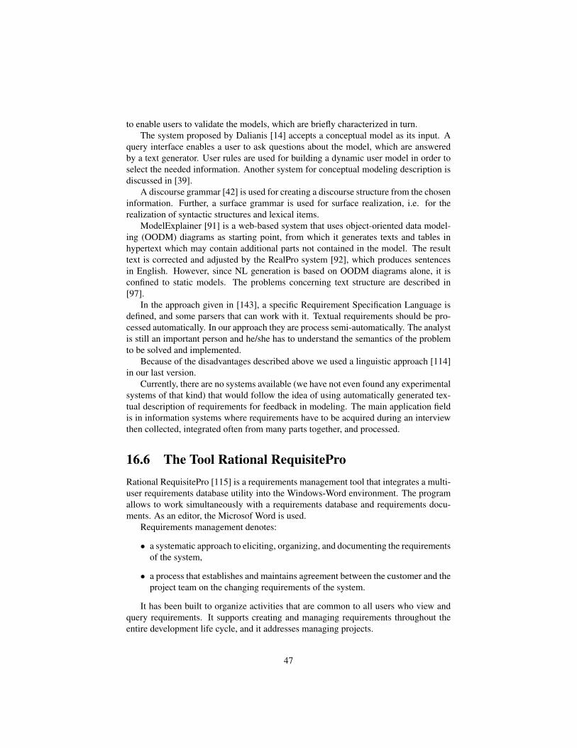
to enable users to validate the models, which are briefly characterized in turn.The system proposed by Dalianis [14] accepts a conceptual model as its input. A
query interface enables a user to ask questions about the model, which are answeredby a text generator. User rules are used for building a dynamic user model in order toselect the needed information. Another system for conceptual modeling description isdiscussed in [39].
A discourse grammar [42] is used for creating a discourse structure from the choseninformation. Further, a surface grammar is used for surface realization, i.e. for therealization of syntactic structures and lexical items.
ModelExplainer [91] is a web-based system that uses object-oriented data model-ing (OODM) diagrams as starting point, from which it generates texts and tables inhypertext which may contain additional parts not contained in the model. The resulttext is corrected and adjusted by the RealPro system [92], which produces sentencesin English. However, since NL generation is based on OODM diagrams alone, it isconfined to static models. The problems concerning text structure are described in[97].
In the approach given in [143], a specific Requirement Specification Language isdefined, and some parsers that can work with it. Textual requirements should be pro-cessed automatically. In our approach they are process semi-automatically. The analystis still an important person and he/she has to understand the semantics of the problemto be solved and implemented.
Because of the disadvantages described above we used a linguistic approach [114]in our last version.
Currently, there are no systems available (we have not even found any experimentalsystems of that kind) that would follow the idea of using automatically generated tex-tual description of requirements for feedback in modeling. The main application fieldis in information systems where requirements have to be acquired during an interviewthen collected, integrated often from many parts together, and processed.
16.6 The Tool Rational RequisiteProRational RequisitePro [115] is a requirements management tool that integrates a multi-user requirements database utility into the Windows-Word environment. The programallows to work simultaneously with a requirements database and requirements docu-ments. As an editor, the Microsof Word is used.
Requirements management denotes:
• a systematic approach to eliciting, organizing, and documenting the requirementsof the system,
• a process that establishes and maintains agreement between the customer and theproject team on the changing requirements of the system.
It has been built to organize activities that are common to all users who view andquery requirements. It supports creating and managing requirements throughout theentire development life cycle, and it addresses managing projects.
47

In difference to TESSI (Section 16.8), it does not offer a design using the corre-sponding UML-model. RequisitePro supports the transition from a set of not structuredtext documents to a hierarchically organized form of specification texts. Hierarchi-cal requirement relationships are one-to-one or one-to-many, parent-child relationshipsbetween requirements of the same type. Use hierarchical relationships to subdivide ageneral requirement into more explicit requirements.
16.6.1 The model used in RequisiteProThe model used in RequisitePro contains:
• Packages
Within each project, requirements artifacts are organized in packages. A packageis a container that can contain requirements documents, requirements, views,and other packages. You can place related artifacts in a single package, andthis organization makes it easier for you to view them and to manipulate thedata. You can configure your packages as necessary to facilitate your work. Anartifact cannot appear in more than one package, but you can move it from onepackage to another. You can create a package within another package. All projectpackages are shared by all project users. Within a package, artifacts are listedin the following order: documents (alphabetically by name), views (by type andthen alphabetically within the type), and requirements (by type and then by tag).
• Documents
Documents in RequisitePro are more or less documents in Word but a few changeswere introduced to exercise security control and to prevent conflicts. Requi-sitePro manages requirements directly in the project documents. When a require-ments document is built, RequisitePro dynamically links it to a database, whichallows rapid updating of information between documents and views. Whenyousave revisions, they are available to team members and others involved with theproject.With RequisitePros version tracking, you can easily review the changehistory for a requirement, a document, or the whole project.
• Requirement types - are used to classify similar requirements so they can beefficiently managed.
• Requirement attributes
Each type of requirement has attributes, and each individual requirement hasdifferent attribute values. For example, requirements may be assigned priori-ties, identified by source and rationale, delegated to specific sub-teams withina functional area, given a degree-of-difficulty designation, or associated with aparticular iteration of the system.
Even without displaying the entire text for each requirement, we can learn a greatdeal about each requirement from its attribute values.
In more detailed types of requirements, the priority and effort attributes may havemore specific values (for example, estimated time, lines of code) with which
48

to further refine scope. This multidimensional aspect of a requirement, com-pounded by different types of requirements (each with its own attributes) is es-sential to organizing large numbers of requirements and to managing the overallscope of the project.
Attribute information may include the following: the relative benefit of the re-quirement, the cost of implementing the requirement, the priority of the require-ment, the difficulty or risk associated with the requirement, the relationship ofthe requirement to another requirement.
• Views
Rational RequisitePro views use tables or outline trees to display requirementsand their attributes or the traceability relationships between different requirementtypes. RequisitePro includes powerful query functions for filtering and sortingthe requirements and their attributes in views. A view is an environment foranalyzing and printing requirements. You can have multiple views open at onetime, and you can scroll to view all requirements and attributes in the table ortree.
RequisitePro views are windows to the database. Views present informationabout a project, a document, or requirements graphically in a table (matrix) orin an outline tree. Requirements, their attributes, and their relationships to eachother are displayed and managed in views. RequisitePro includes query functionsfor filtering and sorting the requirements and their attributes in views.
Three kinds of views can be created:
The Attribute Matrix displays all requirements of a specified type. Therequirements are listed in the rows, and their attributes appear in the columns.
Traceability Matrix displays the relationships (traceability) between twotypes of requirements.
Traceability Tree displays the chain of traceability to or from requirementsof a specified type.
All views display hierarchical relationships, and you can use the TraceabilityMatrix and Traceability Tree to display hierarchical relationships that are markedsuspect.
16.6.2 Traceability in RequisiteProTraceability links requirements to related requirements of same or different types. Req-uisitePros traceability feature makes it easy to track changes to a requirement through-out the development cycle. Without traceability, each change would require a reviewof your documents to determine which, if any, elements need updating.
If either end-point of the connection is changed, the relationship becomes suspect.If you modify the text or selected attributes of a requirement that is traced to or tracedfrom another requirement, RequisitePro marks the relationship between the two re-quirements suspect.
49

After a view into the database of requirements is created, it can be refined by query-ing (filtering and sorting). There are not more advanced concepts (ontology technol-ogy) present.
16.7 The Tool RATIn [142], the recommended analysis structure is specified in Fig. 16.1 as:
Figure 16.1: Natural language processing - overview
16.7.1 Controlled Syntax for Writing RequirementsThe tool RAT [142] supports a set of controlled syntaxes for writing requirements. Thisset includes the following Standard Requirements Syntax. This is the most commonlyused syntax for writing requirements and is of the form:
Standard Requirement syntax:
<agent> <modal word> <action> <rest>
Where,
<agent>, <action>, <modal word>
are phrases in their respective glossaries and
50

<rest>
is the remainder of the sentence and can consist of agents, actions or any other wordsand is defined as:
<rest>: [<anyword> | <agent> | <action>]*
Conditional Requirements Syntax: There are a number of conditional requirementssupported by RAT. For brevity, we will only discuss the most common condition syn-tax:
<if> <condition> <then> <StandardRequirement>
For example, consider the following requirement: If the user enters the wrong pass-word, then the system shall send an error message to the user. In the case, user entersthe wrong password is the condition. The part after then is treated like a standardrequirement.
Business Rules Syntax: RAT treats all requirements that start with all, only andexactly as business rules. An example is: Only the members of payroll department willbe able to access the payroll database.
16.7.2 User-Defined Glossaries and Document ParsingRAT uses three types of user glossaries to parse requirements documents:
• agent glossary - An agent entity is a broad term used to denote systems, subsys-tems, interfaces, actors and processes in a requirements document. The agentglossary contains all the valid agent entities for the requirements document. Itcaptures the following information about each agent: name of the agent, imme-diate class and super-class of the agent and a description of the agent. The classand parent of the class field of the glossary are used to load the glossary into thesemantic engine.
• action glossary- The action glossary lists all the valid actions for the requirementsdocument. It has a similar structure to the agent glossary. Examples of actionsare generate, send and allow.
• modal word glossary - The modal word glossary lists all the valid modal wordsin the requirements document. Examples of modal words are must and shall.
As a requirement is parsed according to the syntax rules given above, structuredcontent is extracted for each requirement. This structured content is used for both thesyntactic and semantic analyses. The extracted structured content contains:
• Type of requirement syntax (standard, conditional, business rule)
• All agents, actions and modal words for all the requirements
• Different constituents of conditional requirements.
51

16.7.3 Classification of problematic phrasesCertain phrases frequently result in requirements that are ambiguous, vague or mislead-ing. The problematic use of such phrases has been well documented in the requirementsliterature. A classification of problematic phrases is presented in [34]. In [155], a listof such words is given and it is explained how to correct requirements that use them.
A list of problematic phrases is stored in a user-extensible glossary called the prob-lem phrase glossary.
16.7.4 Semantic AnalysisMuch of the domain knowledge can be captured using domain-specific ontologies toprovide a deeper analysis of requirements document. The crux of the approach in [142]is to create a semantic graph for all requirements in the document based on the extractedcontent.
In RAT, users can use the requirements relationship glossary to enter domain spe-cific knowledge. The requirements relationship glossary contains a set of requirementclassification classes, its super-class, keywords to identify that class and the relation-ships between the classes.
The fundamental belief in [142] is that once a requirements document is trans-formed into a semantic graph (represented as an OWL ontology), users can query fordifferent kinds of relationships that are important to them. Here are the steps that RATuses to create the semantic graph (graphically depicted in Figure 16.2) from a require-ments document:
Figure 16.2: Core requirements ontology
52

• The core requirements ontology is in the Semantic Engine. It is basic a require-ments ontology with different types of requirements formats (standard, businessrule and conditional) and the information that each of them contain.
• Using the agent and action glossaries to create the agent and action classes andinstances of agents and actions.
• Using the requirement relationship glossary to create requirements classificationclasses and their relationships.
• Using the extracted structured content (enhanced by requirement classificationinformation) to create instances of requirements.
16.7.5 Implementation Details and Early User Evaluation of RATRAT has currently been created as a plug-in for Microsoft Word 2003/7 using VisualBasic for Applications. The Glossaries are currently also Word documents. The Se-mantic Engine leverages the reasoning capabilities of Jena [45] and is implemented inJava. Protege was used to create the OWL [145] ontologies. The Jena semantic engineis used for the reasoning and SPARQL [151] is used for the query language.
Currently, an early version of this tool without the full semantic analysis enginewill be proved, at four client teams. In these pilots, 15 requirements analysts have usedRAT to process more than 10,000 requirements.
16.8 The Tool TESSIIn tool TESSI [83], [84], [154], [87], [88], we offer a textual refinement of the require-ments specification that can be called requirements description. Working with it, theanalyst is forced by the supporting tool TESSI to complete and explain requirementsand to specify the roles of words in the text in the sense of the object-oriented analysis.
During this process, a UML model will automatically be built by TESSI. The pro-cess is driven partially automatically and partially by the analyst’s decisions. In theold release of TESSI, the process of UML-elements identification was based on humandecision. In the last release of TESSI, the automation of this process was constructedusing methods of natural languages processing; human interaction is often necessaryto correct and complete the model.
16.8.1 Architecture and DataflowWe argue that there is a gap between the requirements definition in a natural languageand the requirements specification in some semi-formal graphical representation. Theanalyst’s and the user’s understanding of the problem are usually more or less differentwhen the project starts. Usually, the first possible time point when the user can validatethe analyst’s understanding of the problem is when a prototype starts to be used andtested.
This model will be used:
53
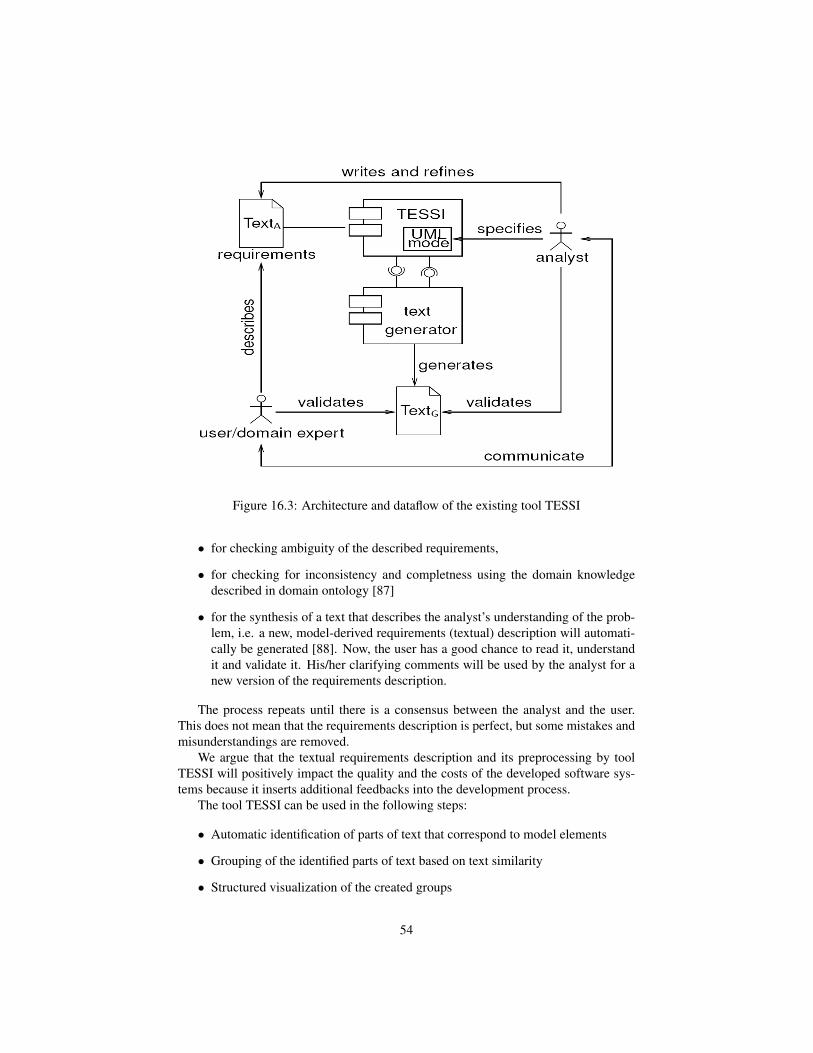
Figure 16.3: Architecture and dataflow of the existing tool TESSI
• for checking ambiguity of the described requirements,
• for checking for inconsistency and completness using the domain knowledgedescribed in domain ontology [87]
• for the synthesis of a text that describes the analyst’s understanding of the prob-lem, i.e. a new, model-derived requirements (textual) description will automati-cally be generated [88]. Now, the user has a good chance to read it, understandit and validate it. His/her clarifying comments will be used by the analyst for anew version of the requirements description.
The process repeats until there is a consensus between the analyst and the user.This does not mean that the requirements description is perfect, but some mistakes andmisunderstandings are removed.
We argue that the textual requirements description and its preprocessing by toolTESSI will positively impact the quality and the costs of the developed software sys-tems because it inserts additional feedbacks into the development process.
The tool TESSI can be used in the following steps:
• Automatic identification of parts of text that correspond to model elements
• Grouping of the identified parts of text based on text similarity
• Structured visualization of the created groups
54

Figure 16.4: TESSI - Creating and relation between model elements
• Editing of the created groups
• Manuel identification of the relevant parts of text
Searching by help of phrases or regular expressions
Appending the text parts found to the corresponding group
• Linking a model element and a group
Choice of the existing model element
Creating of a new model element
The UML-elements identified are connected to the relevant parts of text (in thesequel we speak about words only, eventhough it can be a phrase). All occurrencies ofthese words are highlighted in color, so the analyst can see the impact of its modelingdecision.
The problem is that occurrence of such a word is stated out of the context (withoutnatural language parsing process). Here, the ambiguity of natural languages makes dif-ficulties. Eventhough, the analyst should try to avoid the ambiguity when formulating
55

requirements, mistakes are supposed to occur. This is one of reasons why methods ofnatural language processing are unavoidable in requirements engineering.
The automatic search for artefacts in textuell requirements needs artefacts identi-fication templates (rules). Such templates (rules) can be described as an algorithm, asa part of text, e.g. as a regular expression. To define these templates, a template typedefinition using the language TPL (Tree Pattern Language [153]) is a suitable construc-tion.
The language TPL uses regular expressions for information extraction from trees.It contains operators for tree traversing and methods for testing of node properties.
16.8.2 Natural language analysis in TESSI - using UIMAIn TESSI, the system for NLP processing UIMA (Unstructured Information Manage-ment Architecture) was used [26], [27], [153]. It is an OpenSource-Project and it offersan Apache UIMA-framework, a Java implementation, and a set of Eclipse-plugins.
UIMA is an architecture of analysis engines that can provide an analysis of a docu-ment in natural language. The basic data structure where all analysed objects are storedis called Common Analysis Structure (CAS). It is an object-oriented hierarchical struc-ture. Parts of text are denoted by annotation as positions where the part of text beginnsand ends.
Primitive Analysis Engines can be combined (aggregated) into Agregated AnalysisEngines. In Figure 16.5, there is an aggregated analysis engine Full Parser.
The results of text document analysis using UIMA aggregated engines are inputsfor functions that offers candidates of artefacts (model elements) produced from textualrequirements automatically.
The artefacts can be stored and managed as parts of ontologies. So, the first modelof textual requirements is an ontology.
16.8.3 Ontologies in TESSI for Building UML ModelOften, ontologie are used to represent domain concepts. In TESSI, ontologies containinstances of such concepts and our knowledge about these instances. These conceptsdetermine types of requirements on the system to be implemented. We use conceptsUseCase, Actor, Class, Object, Attribute known from object-oriented modeling. Theimport mechanism supports to recombine various ontologies.
Ontologies serve for collecting information during the requirments elicitation. Theydo not substitute the UML model. As we show later on, reasoning in ontologies is usedin TESSI to provide the very first feedback of the requirements quality.
In TESSI, ontologies are implemented using the Jena-framework [45] for semanticweb applications. Jena can manage the RDF-graphs completely in the main memoryor in a relational database. This property enables processing of models regardless oftheir size.
56

Figure 16.5: UIMA - Aggregated Analysis Engine
57

16.8.4 Grammatical Templates for Identification of Parts of UMLModel
Actions Find Artifact and Find Properties start searching for instances of concepts andtheir properties (realtionships) in text documents of requirement specifications. Theuser of TESSI has the possibility to complete or change the automatic search results[154] by manual corrections.
For searching artifacts that can represent the concept Class, the following TPL-expression [153] was used:
(Phrase & { tag == "NP" } !<< {tag =˜ /ˆ(NP|VP|CD|PR|CC|)/}) |( {tag =˜ /ˆNN/} >>(Phrase &{ tag == "NP" } << {tag =˜ /ˆ(NP|VP|CD|PR|CC|)/}))
This expression (abbreviations from PennTreebank [98], [126]) has the followingmeaning:
Find such noun phrases (NP) that do not contain other noun phrases (NP), verbalphrases (VP), cadinal numerals (CD - e.g. one, two, 3), pronouns (PR*) or coordinatingconjunctions (CC - e.g. and, or), and nouns (NN*) that do not belong to a noun phrasefullfilling the conditin above.
For searching artifacts that can represent the the artifact Book of concept Classaccording to the Property hasAttribute, the following TPL-expression [153] was used:
class:* >> (c:Clause << #class << vp:({tag == "VP"} ,, #class))join[vp]np:({tag == "NP"} !<< {tag =˜ /ˆ(NP|VP|CD|PR|CC|)/})?. ({tag == "PP"} <<(np2:{tag =˜ /ˆ(NN|NP)/} !<<{tag =˜ /ˆ(NP|VP|CD|PR|CC|)/}))-> np, np2
This TPL-expression searches in a sentence (Clause) given by the text context(class:*) that references the concept class. The sentence should contain a verbal phrase(VP) that follows the class reference in the same sentence. In the verbal phrase found,all noun phrase (NP) will be tested that fullfil a specific condition. This condition isbased on grammatical inspection an co-ocurrence and is given in manual.
The OWL ontologies are based on description logic. The advantage is that thereis a reasoning guaranted over used concepts and properties. It includes transitivity,inversion, and symmetry.
A similar approach is given in [143].
58

16.8.5 Ontologies in TESSI for Checking ConsistencyUsing experiences given in [96], we described the domain ontology in Protege andapply ontology reasoning (e.g. the inference engine in Pellet - for checking classes)first for domain ontology checking, then for requirements problem ontology checking,and last for checking whether the requirements problem ontology subsumes the domainontology.
The steps of the requirements processing that uses ontologies are the following:
• building a domain ontology in OWL using Protege, i.e. domain ontology de-scription based on OWL and SWRL based is constructed by domain experts atfirst and then transformed into the concepts set of Pellet and rules set of Jess.
• checking the domain ontology for consistency using Pellet (class hierarchy) andJess (rules),
• the analyst writes a text description of requirements based on interviews withusers,
• the analyst builds the UML model from a textual description of requirementssupported by our tool TESSI,
• conversion of requirements described as a UML model to a problem ontology inOWL using convertor ATL (we used ATL because RacerPro is not public),
• checking the problem ontology for mutually consistency,
• checking the problem ontology by confronting it with the domain ontology,
• identifying inconsistency problems,
• finding the corresponding parts in the former textual description of requirementsand correcting them,
• building a new UML model based on corrected textual description of require-ments,
• after iterations when no ontology conflicts will be found a new textual descrip-tion of requirements will be automatically generated that corresponds to the lastiteration of the UML model,
• before the UML model will be used for design and implementation the user andthe analyst will read the generated textual description of requirements and lookfor missing features or misunderstandings,
• problems found can start the next iteration from the very beginning,
• after no problems have been found the UML model in form of a XMI-file willbe sent to Rational Modeler for further processing.
59

Ontology ofdomain
(in Protégé)UML model
Checking for consistency and
correctness
Ontology of requirements(in Protégé)
Ontology asUnion of domain and requirements
Checked Requirements
RequirementsDomain Knowledge
Converterfrom OUP profile
to OWL
Figure 16.6: The component for consistency checking
16.8.6 Feedbacks in TESSIThe UML model will be used for the synthesis of a text that describes the analyst’sunderstanding of the problem, i.e. a new, model-derived requirements description willautomatically be generated. Now, the user has a good chance to read it, understandit and validate it. His/her righting comments will be used by the analyst for a newversion of the requirements description. The process repeats until there is a consensusbetween the analyst and the user. This does not mean that the requirements descriptionis perfect, but some mistakes and misunderstandings are removed.
We argue that the textual requirements description and its preprocessing by TESSIwill positively impact the quality and the costs of the developed software systems be-cause it inserts additional feedbacks in the development process.
More details are given in the Section 14.1.
60

Chapter 17
Open problems
• UML-model automatically derived from text of requirements by NLP
In TESSI, we used templates (patterns) describing part-of-speech taggingcorresponding to classes and to relationships. The used templates were specifiedmanually following the grammatical inspection. We should find templates forother parts of the UML model automatically that should be derived from textualrequirements. A similar approach is given in [143].
Searching templates of POS-tags-trees can be done manual (as in TESSI)or automatically. The automated method assumes to use machine learning to getclassified cases for supervised methods of classification. Experiments on largedata will give statistical results (e.g. presicion, recall, F-measure).
• Inconsistency checking
Is there any tool for checking consistency of OCL rules?
Where is the limit of rule complexity for executable consistency checking?
• Completeness
Using domain ontology, there is a possibility to generate some requests automat-ically that should complete the gaps between knowledge stored in the domainontology and the problem ontology that corresponds to the requirement specifi-cations.
How to generate questions that can cause getting requirements more com-plete?
How can be used domain ontology for improving completeness of require-ments?
• Scope
How to generate possible scopes for requirements? Th project scope is very im-portant with respect to the limited budget of the customer. Requirements are notunambiguous in many ways. One of ambiguity is the solution ”luxury” expecta-tion of the customer and the modest implementation of the analyst.
61

Is it possible to reveal more variants of solution, may be more paths inontologies, that solve the requirements but have various costs?
• Traceability
How to generate links between text segments of requirements, UML-elements,and black-box test cases automatically?
The others open problem will be completed later.
62

AcknowledgmentsThis work was partially supported by the Grant Agency of the Czech Republic projectP103/11/1489.
63

Bibliography
[1] Abbott, R.J.: Program design by informal english descriptions. Communicationsof the ACM, 26(11), pp. 882894, 1983.
[2] Berry, D.M.: Formal Methods: The Very Idea - Some Thoughts About Why TheyWork When They Work.
[3] Kalb, H. et al.: BlogForever: D4.1 User Requirements and Platform SpecificationsReport. Technische Universitt Berlin, 2011.
[4] Banerjee, S.: Adapting the Lesk Algorithm forWord Sense Disambiguation toWordNet. Master Thesis, University of Minnesota, 2002.
[5] Boehm, B.: Software Engineering Economics. Prentice-Hall, Englewood Cliffs,NJ.
[6] Boehm, B.: Identifying Quality Requirements Conflicts. IEEE Software, pp. 25-35, March 1996, 1996.
[7] de Bruijn, F., Dekkers, H.L.: Ambiguity in Natural Languages Software Require-ments: A Case Study. In: Wieringa,R. and Persson, A. (Eds.): REFSQ 2010, LNCS6182, pp. 233-247, Springer, 2010.
[8] Carreno, R.S., et al.: An ontology-based approach to knowledge acquisition fromtext. Cuadernos de Filologia Inglesa, 9(1), pp. 191-212 (in English), 2000.
[9] Christopherson, L.L.: Use of an ontology-based note-taking tool to improve com-munication between analysts and their clients. A Masters Paper for the M.S. inI.S.degree, University of North Carolina, November, 2005.
[10] Coad, P., Yourdon, E.: Object-Oriented Analysis. Prentice Hall, 1991.
[11] CHAOS Report, The Standish Group, 1995.
[12] Cranefield, S., Purvis, M.: UML as an Ontology Modelling Language. In: Proc.of the IJCAI99 Workshop on Intelligent Information Integration, Sweden, 1999.
[13] Cycorp Inc., ResearchCyc. http://research.cyc.com
64

[14] Dalianis, H.: A method for validating a conceptual model by natural languagediscourse generation. In: Loucopoulos, P. (Ed.): Advanced Inforamtion SystemsEngineering, CAiSE92, Manchester, LNCS, Vol. 593, pp. 425-444, Springer, 1992.
[15] Davis, A., Hickey, A.: A Quantitative Assessment of Requirements EngineeringPublications - 1963-2008. In: M. Glinz and P. Heymans (Eds.): REFSQ 2009,LNCS 5512, pp. 175189, Springer, 2009.
[16] Deemter, K. V., Krahmer, E., Theune, M.: Real versus template-based natural lan-guage generation: A false opposition? In: Computer Linguist., Vol. 31(1), pp.15-24, 2005.
[17] Deeptimahanti, D. K., Sanyal, R.: An Innovative Approach for Generating StaticUML Models from Natural Language Requirements. Advances in Software Engi-neering, Springer, 2009
[18] DeSmedt, K., Horacek, H., and Zock, M.: Architectures for natural language gen-eration: Problems and Perspectives. In: Trends in Natural Language Generation:An Articial Intelligence Perspective. Eds.:Adorni,G., Zock,M., Lecture Notes inArtificial Intelligence, 1036, pp. 17-46, Springer, 1996.
[19] Dorfman, M., and R.H. Thayer (eds.): Standards, Guidelines, and Examples onSystem and Software Requirements Engineering. IEEE Computer Society Press,Los Alamitos, CA, 1990.
[20] Dressler, W., de Beaugrande, R.: Introduction to text linguistics. Longman, Lon-don, 8th edition, 1996.
[21] Emmerich, W.,Kroha, P., Schafer, W.: Object-Oriented Database ManagementSystems for Construction of CASE Environments. In: Marik, V. et al (Eds.): Pro-ceedings of the 4th International Conference DEXA’93, Lecture Notes in Com-puter Sciences, No. 720, Springer, 1993.
[22] Easterbrook, S., Callahan, J., and Wiels, V.: V & V Through Inconsistency Track-ing and Analysis. Proceedings of International Workshop on Software Specifica-tion and Design, Kyoto, 1998.
[23] Eriksson, H.: Using JessTab to integrate Protege and Jess, Intelligent Systems,Volume 18, Issue 2, pp. 43-50, IEEE Mar-Apr, 2003.
[24] Falbo, R.d.A., Guizzardi, G., Duarte, K.C.: An ontological approach to domainengi- neering. In: Proceedings of the 14th International Conference on SoftwareEngineering and Knowledge Engineering, 2002.
[25] Faure, D., Nedellec, C.: Asium: Learning subcategorization frames and restric-tions of selection. In: Y. Kodratoff (Ed.): 10th European Conference on MachineLearning (ECML 98) Workshop on Text Mining, Chemnitz Germany, April 1998.
[26] Ferrucci, D., Lally, A.: Accelerating Corporate Research in the Development,Application and Deployment of Human Language Technologies, Techn. Ber., IBMT.J. Watson Research Center, 2003.
65
[27] Ferrucci, D., et al.: Towards an Interoperability Standard for Text and Multi-Modal Analytics, Techn. Ber., IBM Research Division, November 2006.
[28] Flores, J.J.G.: Semantic Filtering of Textual Requirements Descriptions. In: Nat-ural Language Processing and Information Systems, pp. 474483, 2004
[29] Gasevic, D., Djurevic, D., Devedzic, V.: Model Driven Architecture and Ontol-ogy Development, Springer, 2006.
[30] Gelhausen, T.: Modellextraktion aus naturlichen Sprachen. Dissertation am Insti-tut fur Programmstrukturen und Datenorganisation, Lehrstuhl Prof. Dr. Walter F.Tichy, Fakultat fur Informatik, Karlsruher Institut Institut fur Technologie (KIT),(In German), 2010
[31] Gemeinhardt, L.: Connecting TESSI and Rational Rose by means of XML.Project Report, TU Chemnitz, 2000. (In German)
[32] Gervasi, V., Zowghi, D.: On the Role of Ambiguity in RE. In: Wieringa,R. andPersson, A. (Eds.): REFSQ 2010, LNCS 6182, pp. 248-254, Springer, 2010.
[33] Gildea, D., Jurafsky, D.: Automatic labeling of semantic roles. ComputationalLinguistics, Vol. 28, pp. 245-288, MIT Press, 2002.
[34] Gnesi, S., Lami, G., Trentanni, G.: An automatic tool for the analysis of naturallanguage requirements. CSSE Journal 20(1), pp. 5362, 2005.
[35] Gordon, A., Swanson, R.: Generalizing semantic role annotations across syn-tactically similar verbs. Proceedings of the 2007 meeting of the Association forComputational Linguistics (ACL-07), Prague, pp. 23-30, 2007.
[36] Gruber, T.: A translation approach to portable ontologies. Knowledge Acquisi-tion, Vol. 5(2), pp. 199220, 1993.
[37] Guizzardi, G., Falbo, R.A., Pereira Filho, J.G.: Using Objects and Patterns toImplement Domain Ontologies. In: Proc. of the 15th Brazilian Symposium onSoftware Engineering, Rio de Janeiro, Brazil, 2001.
[38] Hillairet, G.: ATL Use Case - ODM Implementation (Bridging UML and OWL),http://www.eclipse.org/m2m/atl/usecases/ODMImplementation.
[39] Hoppenbrouwers, J., van der Vos, A., Hoppenbrouwers, S.: Nl structures and con-ceptual modelling: the kiss case. In: Proceedings of the 2nd. International Work-shop on the application of Natural Language to Information Systems (NLDB96).IOS Press, Amsterdam, The Netherlands, 1996.
[40] Horacek, H.: New Concepts in Natural Language Generation. Pinter Publishers,1993.
[41] Houpt, J.: Ambiguous Prepositional Phrase Resolution by Humans. Master ofScience Artificial Intelligence School of Informatics University of Edinburgh,2006.
66

[42] Hovy, E.: Automated discourse generation using discourse structure relations.Artificial Intelligence, Vol. 63, Nr.1-2, 1993.
[43] Jacobson, I.: Object-Oriented Software Engineering: A Use Case Driven Ap-proach. Addison-Wesley, 1992.
[44] Janetzko, R.: Applying ontology for checking of requirements specification,M.Sc. Thesis, Faculty of COmputer Science, TU Chemnitz, 2009. (In German)
[45] Jena Documentation, 2007. URL http://jena.sourceforge.net/documentation.html
[46] Jiang, D., Zhang, S., Wang, Y.: Towards a formalized ontologybased require-ments model. Journal of Shanghai Jiaotong University (Science), 10(1), pp. 34-39,2005.
[47] Jin, Z.: Ontology-based requirements elicitation automatically. Chinese J. Com-puters, 23(5), pp. 486-492, May 2000.
[48] Jin, Z.: Ontology-Based Requirements Elicitation. Journal of Computers, 23(5),pp. 486-492, 2003.
[49] Jin, Z., Bell, D.A., et al.: Automated requirements elicitation: Combining amodel-driven approach with concept reuse. International Journal of Software En-gineering and Knowledge Engineering, 13(1), pp. 53-82, 2003.
[50] Johnson, W.L., Feather, M.S., Harris, D.R.: Representation and presentation ofrequirements knowledge. IEEE Transactions on Software Engineering, pp. 853-869, 1992.
[51] Jones, C.: Software challenges. Comput. industry 28, 10, pp. 102103, 1995.
[52] Jones, C.: Patterns of Software Systems Failure and Success. International Thom-son Computer Press, London, 1996.
[53] Kaiya, H., Saeki, M.: Using Domain Ontology as Domain Knowledge for Re-quirements Elicitation. In: Proceedings of 14th IEEE International RequirementsEngineering Conference, Minnesota, pp. 186-195, 2006.
[54] Kamsties, E., Daniel M. Berry, D.M., Paech, B.: Detecting Ambiguities in Re-quirements Documents Using Inspections.
[55] Karpati, P., Sindre, G., Opdahl, A.L.: Visualizing Cyber Attacks with MisuseCase Maps. In:
[56] Kim, Y.-G.: Effects of Conceptual Modeling Formalism on User Validation andAnalyst Modeling of Information Requirements. PhD. Thesis, University of Min-nesota, 1990.
[57] Kiyavitskaya, N., Zeni, N., Mich, L., Mylopoulos, J.: Experimenting with Lin-guistic Tools for Conceptual Modelling: Quality of the Models and Critical Fea-tures. In: Meziane,F., Metais, E. (Eds.):Proceedings of NLDB 2004, LNCS 3136,pp. 135-146, 2004.
67

[58] Klein, D. and Manning, C.: Accurate unlexicalized parsing. In Proceedings ofthe 41st Annual Meeting of the Association for Computational Linguistics (ACL2003), pp.423-430, 2003.
[59] Klein, D. and Manning, C.: Fast exact inference with a factored model for naturallanguage parsing. In: NIPS, Volume 15, MIT Press, 2003.
[60] Kof, L.: Translation of Textual Specifications to Automata by Means of DiscourseContext Modeling. In: REFSQ ’09 Proceedings of the 15th International Work-ing Conference on Requirements Engineering: Foundation for Software Quality,Springer, 2009
[61] Kof, L.: Using Application Domain Ontology to Construct an Initial SystemModel. In: IASTED International Conference on Software Engineering, 2004.
[62] Kof, L.: Text Analysis for Requirements Engineering. Ph.D. Thesis, TU Mnchen,2005.
[63] Kof, L.: Natural Language Processing: Mature Enough for Requirements Docu-ments Analysis? In: Montoyo, A.; Munoz, R., Metais, E. (Eds.): NLDB, LNCS3513, 91-102, Springer, 2005.
[64] Kof, L., Gacitua, R., Rouncefield, M., Sawyer, P.: Ontology and Model Aligmentas a Means for Requirements Validation. In: Proceedings of ICSC’10, pp. =46-51,2010.
[65] Kof, L.: From Requirements Documents to System Models: a Tool for InteractiveSemi-Automatic Translation.
[66] Kof, L., Schatz, B.: Combining aspects of reactive systems. In: Broy, M., Za-mulin, A.V. (eds.) PSI 2003. LNCS, Vol. 2890, pp. 344349, Springer, 2004.
[67] Kof, L.: Scenarios: Identifying missing objects and actions by means of compu-tational linguistics. In: 15th IEEE International Requirements Engineering Con-ference, New Delhi, India, pp. 121130. IEEE Computer Society Conference Pub-lishing Services, Los Alamitos, 2007.
[68] Kof, L.: Treatment of Passive Voice and Conjunctions in Use Case Documents.In: Kedad, Z.,Lammari, N., Metais, E., Meziane, F., Rezgui, Y. (eds.) NLDB 2007.LNCS, vol. 4592, pp. 181192, Springer, 2007.
[69] Kof, L.: From Textual Scenarios to Message Sequence Charts: Inclusion of Con-dition Generation and Actor Extraction. In: 16th IEEE International RequirementsEngineering Conference, Barcelona, Spain, pp. 331332. IEEE Computer Society,2008.
[70] Gleich, B., Creighton, O., Kof, L.: Ambiguity Detection: Towards a Tool Ex-plaining Ambiguity Sources.
[71] Kof, L.: Requirements Analysis: Concept Extraction and Translation of TextualSpecifications to Executable Models.
68

[72] Kof, L.: From Textual Scenarios to Massage Sequence Charts: Inclusion of Con-dition Generation and Actor Extraction
[73] Kof, L.: On the Identification of Goals in Stakeholders Dialogs
[74] Kof, L.: Treatment of Passive Voice and Conjunctions in Use Case Documents
[75] Kof, L.: Scenarios: Identifying Missing Objects and Actions by MEans of Com-putational Linguistics
[76] Kof, L.: Natural Language Processing: Mature Enough for Requirements Docu-ments Analysis?
[77] Kof, L.: An Application of Natural Language Processing to Domain Modelling -Two Case Studies, 2004.
[78] Kof, L.: Application Domain Ontology to Construct an Initial System Model
[79] Korner S. J., Gelhausen T.: Improving Automatic Model Creation Using On-tologies. In Knowledge Systems Institute (ed.): Proceedings of the Twentieth In-ternational Conference on Software Engineering - Knowledge Engineering, pp.691-696, 2008.
[80] Krachina, O., Raskin, V.: Ontology-Based Inference Methods. Tech report num-ber CERIAS TR 2006-76.
[81] Kroha, P.: Objects and Databases. McGraw-Hill, 1993.
[82] Kroha, P.: Softwaretechnologie. Prentice Hall, 1997 (in German).
[83] Kroha, P., Strauß, M.: Requirements Specification Iteratively Combined with Re-verse Engineering. In: Plasil, F., Jeffery, K.G. (Eds.): Proceedings of SOFSEM’97:Theory and Practice of Informatics, Lecture Notes in Computer Science, No. 1338,Springer, 1997.
[84] Kroha, P.: Preprocessing of Requirements Specification. In: Ibrahim, M., Kng, J.,Revell, N. (Eds.): Proceedings of DEXA2000, London, Lecture Notes in ComputerScience, No. 1873, Springer, 2000.
[85] Kroha, P., Rosenhainer, L.: Textuelle Anforderungen und Software Migration.In: Kaiser, U., Kroha, P., Winter, A. (Hrsg.): 3. Workshop Reengineering Prozesse(RePro 2006) Software Migration. Informatik Bericht Nr. 2/2006, Institut fr In-formatik, Fachbereich 08, Johannes Gutenberg-Universitt Mainz, November 2006.Reprinted in: GI - Softwaretechnik-Trends, Band 27, Heft 1, Februar 2007.
[86] Kroha, P., Labra Gayo, J. E.: Using Semantic Web Technology in RequirementsSpecifications. Chemnitzer Informatik-Berichte CSR-08-02, ISSN 0947-5125, TUChemnitz, November 2008.
69

[87] Kroha, P., Janetzko, R., Labra, J. E.: Ontologies in Checking for Inconsistencyof Requirements Specification. In: Dokoohaki, N., Zavoral, F., Noll, J.(Eds.): Pro-ceedings of the 3rd International Conference on Advances in Semantic ProcessingSEMAPRO 2009, IEEE Computer Society, Sliema, Malta, October 2009.
[88] Kroha, P., Rink, M.: Text Generation for Requirements Validation. In: Filipe,J., Cordeiro, J.(Eds.): Proceedings of the 11th International Conference EnterpriseInformation Systems - ICEIS 2009, Milano, Lecture Notes in Business InformationProcessing, Nr. 24, pp. 467-478, Springer, May 2009.
[89] Lamsweerde, A.V., Darimont, R., Letier, E.: Managing Conflicts in Goal-DrivenRe- quirements Engineering. IEEE Trans. Software Eng. 24(11), 1998.
[90] Lamsweerde, A.V.: Requirements Engineering: From System Goals to UMLModels to Software Specifications. Wiley, 2009.
[91] Lavoie, B., Rambow, O., Reiter,E.: The ModelExplainer. In: DemonstrationNotes of International Natural Language Generation Workshop, INLG’96, Har-monceux Castle, Sussex, UK, 1996.
[92] Lavoie,B., Rambow, O., Reiter, E.: A Fast and Portable Realizer for next Genera-tion Systems. In: Proceedings of the 5th Conference on Applied Natural LanguageProcessing, ANLP’97, Washington, 1997.
[93] Lee, Y., Zhao, W.: An Ontology-Based Approach for Domain Requirements Elic-itation and Analysis. In: Proceedings of the First International Multi-Symposiumson Computer and Computational Sciences, 2006
[94] Leidenfrost, S.: TESSI in Java. Project report, TU Chemnitz, 1999. (In German)
[95] Li, X., Szpakowicz, S., Stan Matwin, S.: A WordNet-based Algorithm for WordSense Disambiguation, 1995.
[96] Li, Z., Wang, Z., Zhang, A., Xu, Y.: The Domain Ontology and Domain RulesBased Requirements Model Checking. International Journal of Software Engineer-ing and Its Applications, Vol. 1, No. 1, July, 2007.
[97] Mann, W.: Text generation: The problem of text structure. In Natural LanguageGeneration Systems, Eds.: D.D. McDonald, Bolc,L., pp. 47-68, Springer, 1988.
[98] Marcus, M.P., Santorini, B., Marcinkiewicz, M.A.: Building a Large AnnotatedCorpus of English: the Penn Treebank. Computational Linguistics, vol. 19, 1993.
[99] Marneffe, M., MacCartney, B., Manning, Ch.D.: Generating Typed DependencyParses from Phrase Structure Parses. In Proceedings: The International Conferenceon Language Resources and Evaluation LREC 2006.
[100] Mich, L., Franch, M., Novi, I.P.: Market research for requirements analysisusing linguistic tools. Requirements Engineering, Vol. 9, pp. 4056, 2004.
70
[101] Neches, R., Fikes, R.E., Finin, T.: Enabling technology for knowledge sharing.AI Magazine, 12 (3), pp. 36-56, 1991.
[102] Nuseibeh, B., Easterbrook, S., Russo, A.: Leveraging Inconsistency in SoftwareDevelopment. IEEE Computer, April 2000.
[103] Nuseibeh, B., Easterbrook, S.: Requirements Engineering: A Roadmap. Pro-ceedings of International Conference on Software Engineering ICSE-2000, pp. 4-11, Limerick, Ireland, ACM Press, June 2000.
[104] Nuseibeh, B., Haley, C.B., and Foster C.: Securing the Skies: In RequirementsWe Trust. IEEE Computer, 42(9):64-72, September 2009.
[105] Omoronyia, I. et al.: A Domain Ontology Building Process for Guiding Re-quirements Elicitation. In: R. Wieringa, R., and Persson, A. (Eds.): Proceedings ofREFSQ 2010, LNCS 6182, pp. 188202, Springer, 2010.
[106] Paiva, D.: A survey of applied natural language generation systems.http://citeseer.ist.psu.edu/paiva98 survey.html.
[107] Pereira, A.R., Ziviani, N.: Syntactic Similarity of Web Documents. In: Proceed-ings of the First Latin American Web Congress (LA-WEB 2003), IEEE, 2003.
[108] Perrouin, G., Brottier, ., aundry, B., Le Traon, Y.: Composing Models for De-tecting Inconsistencies: A Requirements Engineering Perspective. In: M. Glinzand P. Heymans (Eds.): REFSQ 2009, LNCS 5512, pp. 89103, Springer, 2009
[109] Petre, M.: Why looking isn’t always seeing: Readership skills and graphicalprogramming. Communication of the ACM, Vol. 38, No. 6, pp. 33-42, 1995.
[110] Pohl, K.: Requirements Engineering - Fundamentals, Principles, and Tech-niques. Springer, 2010.
[111] Pomerantz, J.: A Linguistic Analysis of Question Taxonomies. Journal of theAmerican Society for Information Science and Technology, 56(7), pp. 715-728,2005.
[112] RDF Vocabulary Description Language 1.0: RDF Schema. W3C Recommenda-tion 10, February 2004.
[113] Realpro: General english grammar, user manual. 2000.http://www.cogentex.com/papers/realpro-manual.pdf.
[114] Reiter, E., Dale, R.: Building natural language generation systems. In: Studiesin Natural Language Processing, Journal of Natural Language Engineering, Vol.3(1), pp.57-87, 1997.
[115] Rational RequisitePro - User’s Guide. Rational Software Corporation, 2003.
[116] Rational Suite Analyst Studio - Getting Started. Rational Software Corporation,2003.
71

[117] Rink, M.: Text generator implementation for description of UML 2 models.MSc. Thesis, TU Chemnitz, 2008, (In German).
[118] Robertson, S., Robertson, J.: Mastering the Requirements Process. Addison-Wesley, 1999.
[119] Rubin,K., Goldberg,A.: Object Behaviour Analysis. Communication of ACM,Vol. 35, No.9, pp. 48-62, September 1992.
[120] Robinson, M., Bannon, L.: Questioning representations. In: Proceedings ofECSCW, Amsterdam. http://www.ul.ie/ idc/library/papersreports/ LiamBannon/15/QuestFin.html.
[121] Robinson, W.: Interactive Decision Support for Requirements Negotiation. Con-current Engineering: Research & Applications, 2, pp. 237-252, 1994.
[122] Robinson, W., Fickas, S.: Supporting Multiple Perspective Requirements En-gineering. In: Proceedings of the 1st International Conference on RequirementsEngineering (ICRE 94), IEEE Computer Society Press, pp.206-215, 1994.
/bibitemRobinson1997 Robinson,W.: I Didnt Know My Requirements were Con-sistent until I Talked to My Analyst. Proceedings of 19th International Conferenceon Software Engineering (ICSE-97), IEEE Computer Society Press, Boston, USA,May , pp. 17-24, 1997.
[123] Robinson, W., Pawlowski, S.: Managing Requirements Inconsistency with De-velopment Goal Monitors. IEEE Transactions on Software Engineer, Novem-ber/December, 1999.
[124] Robinson, W.N., Pawlowski, S.D., Volkov, V.: Requirements interaction man-agement. ACM Comput. Surv. 35(2), pp. 132190, 2003.
[125] Sagae, K., Gordon, A.: Clustering Words by Syntactic Similarity Improves De-pendency Parsing of Predicate-Argument Structures. International Conference onParsing Technologies (IWPT-09), Paris, pp. 7-9, 2009.
[126] Santorini, B.: Part-of-Speech Tagging Guidelines for the Penn Treebank Project(3rd Revision, 2nd printing), Feb 1995.
[127] Schmid, H.: Probabilistic Part-of-Speech Tagging Using Decision Trees. Pro-ceedings of International Conference on New Methods in Language Processing,Manchester, 1994.
[128] Schmid, H.: Improvements in Part-of-Speech Tagging with an Application toGerman. Proceedings of the ACL SIGDAT-Workshop. Dublin, 1995.
[129] Scott, D., de Souza, C.: Conciliatory planning for extended descriptive texts.Technical Report 2822, Philips Research Laboratory, Redhill.
72

[130] Shibaoka, M., Kaiya, H., Saeki, M.: GOORE: Goal-Oriented and OntologyDriven Requirements Elicitation Method. In: Hainaut, J.-L., Rundensteiner, E.A.,Kirchberg, M., Bertolotto, M., Brochhausen, M., Chen, Y.-P.P., Cherfi, S.S.-S., Do-err, M., Han, H., Hartmann, S., Parsons, J., Poels, G., Rolland, C., Trujillo, J., Yu,E., Zimanyie, E. (eds.): ER Workshops, LNCS, Vol. 4802, pp. 225234, Springer,2007.
[131] Simpson, T., Dao, T.: WordNet-based semantic similarity measurement. URLhttp://www.codeproject.com/cs/library/semanticsimilaritywordnet.asp
[132] Spanoudakis, G., Zisman, A.: Inconsistency Management in Software Engi-neering: Survey and Open Research Issues. In: Chang, S.K.(Ed.): Handbook ofSoftware Engineering and Knowledge Engineering, World Scientific PublishingCo., pp. 329-380, 2001.
[133] Spence, I., Probasco, L.: Traceability Strategies for Managing Requirementswith Use Cases. Rational Software White Paper, 2000
[134] Swartout,B.: GIST English Generator. In: Proceedings of the National Confer-ence on Artificial Intelligence, AAAI’82.
[135] Thayer, R.H., Dorfman, M.: System and software requirements engineering.IEEE Computer Society Press, 1990.
[136] Thayer, R.H.: Software System Engineering: A Tutorial. Computer, April 2002.
[137] Thayer, R.H.: Software Engineering Management. In: Software Engineering:Volume 2: The Supporting Processes, (Eds.):Richard H. Thayer and Mark J. Chris-tensen, IEEE Computer Society Press, Los Alamitos, CA, 2002.
[138] Thiagarajan, R., Manjunath, G., Stumptner, M.: Computing Semantic SimilarityUsing Ontologies. ISWC 08, The International Semantic Web Conference (ISWC),Karlsruhe, 2008.
[139] Toutanova, K., Manning,C.D.: Enriching the Knowledge Sources Used in aMaximum Entropy Part-of-Speech Tagger. In: Proceedings of the Joint SIGDATConference on Empirical Methods in Natural Language Processing and Very LargeCorpora (EMNLP/VLC-2000), pp. 63-70, 2000.
[140] Toutanova, K., Klein, D., Manning, C., and Singer, Y.: Feature-Rich Part-of-Speech Tagging with a Cyclic Dependency Network. In: Proceedings of HLT-NAACL 2003, pp. 252-259, 2003.
[141] Uschold, M., King, M., Moralee, S., Zorgios, Y.: The Enterprise Ontology.Knowledge Engineering Review, 13(1), pp. 31-89, 1998.
[142] Verma, K., Kass, A.: Requirements Analysis Tool: A Tool for AutomaticallyAnalyzing Software Requirements Documents. In: Sheth, A. et al. (Eds.): Pro-ceedings of ISWC 2008, LNCS 5318, pp. 751763, Springer, 2008.
73

[143] Videira, C., Ferreira, D., da Silva, A.: A linguistic patterns approach for re-quirements specification. In: Proceedings of the 32nd EUROMICRO Conferenceon Software Engineering and Advanced Applications (EUROMICRO-SEAA06),2006.
[144] W3C: OWL Web Ontology Language Guide, Feb 2004.
[145] W3C: OWL Web Ontology Language Overview, Jan 2004.
[146] W3C: RDF Primer, Feb 2004.
[147] W3C: RDF Vocabulary Description Language 1.0: RDF Schema, Feb 2004.
[148] W3C: RDF/XML Syntax Specification, Feb 2004.
[149] W3C: Resource Description Framework (RDF): Concepts and Abstract Syntax,Feb 2004.
[150] W3C: SPARQL Protocol for RDF, October 2006.
[151] W3C: SPARQL Query Language for RDF, April 2006.
[152] Weidauer, J.: Implementierung eines Teilsystems fur die Transformation einesOWL-Modells nach UML 2 und Neuentwicklung des Hilfesystems im Rahmendes Projektes TESSI. Master Thesis, TU Chemnitz, 2008
[153] Wenzel, K.: Informationsextraktion aus semistrukturierten Dokumenten mitHilfe von Mustern. Project-Report, Department of Computer Science, Universityof Technology, Chemnitz, 2006 (In German).
[154] Wenzel, K.: Implementierung eines neuen Prototyps fr das CASE-WErkzeugTESSI unter Integration eines Analysesystems fr natrliche Sprache und Ontolo-gien. Master Thesis, Department of Computer Science, University of Technology,Chemnitz, 2007 (In German).
[155] Wiegers, K.: Software Requirements. Microsoft Press, 2003.
[156] Zhu, X., Zhi, Jin: Inconsistency Measurement of Software Requirements Speci-fications an Ontology-Based Approach. In: Proceedings of the 10th IEEE Interna-tional Conference on engineering of Complex Computer Systems, 2005.
74