Formalizing Collaboration-Oriented Service Specifications ...
27
Formalizing Collaboration-Oriented Service Specifications using Temporal Logic Frank Alexander Kraemer and Peter Herrmann Department of Telematics Norwegian University of Science and Technology (NTNU) 7491 Trondheim, Norway {kraemer , herrmann }@item.ntnu.no Abstract In our highly automated engineering approach, reactive services are specified using UML 2.0 collaborations and activities. This enables to focus on complete behaviors between of a set of participants in isolation, and to decompose systems according to the functionalities it should offer. Of course, precise semantics for the specifications are necessary, as we use them as input for model checking and automatic synthesis of components for implementation. For this reason we formalize the concept of collaborations in the temporal logic cTLA by defining the specification style cTLA/c. Collaborations are hereby represented as cTLA processes, and the composition of collaboration can be reduced to process couplings. While cTLA/c is general to capture the semantics of different languages, we show in detail how UML 2.0 activities are mapped to cTLA/c by a set of cTLA processes and production rules. 1 Introduction A networked service is a system offering certain functionalities that are used by concurrently acting entities in its environment. The service functions often render a reactive behavior in the sense that they “main- tain some interaction with their environment” [25]. From a physical point of view, such a system naturally decomposes into its components, that means the distributed entities providing the system functionality. In the setting of a model-driven development approach, the compo- nents may be expressed for example by SDL processes and blocks [11], or UML state machines and composite structures [24]. These compo- nent descriptions form the input for automatic code generation tools (see, e.g., [3, 7, 30]). For a system offering a whole bunch of functionalities to its environ- ment, such a component-based view leads to complex specifications as each component model describes partial aspects of various functional- ities. Instead, we desire a specification style in which a specification block models all aspects of a single functionality facilitating the indi- vidual development, deployment, invocation and maintenance of sepa- rate functionalities. As a functionality is basically a service spanning over several components, we therefore need specifications describing the collaboration of various components. Modeling languages like UML in- teractions [24], MSC [12] and Use Case Maps [4] offer a solution by en- abling the description of both partial and collaborative behaviors. We apply UML 2.0 collaborations to express static properties and UML 2.0 activities to model collaborative behavior [9, 16, 17]. Of course, the need for component models remains as, in the end, the components are the entities which have to be created and deployed on different devices to realize the system. Consequently, we often find system models utilizing diagrams of several types which describe a sys- tem from different viewpoints. This, however, imposes the challenge of keeping the diagrams consistent. Given the need to build services and to adjust their system functions rapidly, approaches that rely on the dis- cipline of its developers to maintain the diagrams manually are rather naive. A consequent way to go is therefore to let developers create only one group of diagrams and infer the others completely automatically, for example by means of model transformations. Several examples [5, 9, 16, 17, 26, 28] illustrate how the notion of collaborations can be used to specify services. All these specifications have in common that they decompose a system according to its tasks, delay the construction of components to a later stage, and identify only participants relevant for the modeled functionality. Such tasks (or sub-functionalities resp. sub-services) often show up in more than one application. They typically have a concise objective or function, result- ing in building blocks which can be used for various service descriptions in a particular application domain. With our approach for the specification by activities, collaborations
Transcript of Formalizing Collaboration-Oriented Service Specifications ...
Formalizing Collaboration-Oriented ServiceSpecifications using Temporal Logic
Frank Alexander Kraemer and Peter HerrmannDepartment of Telematics
Norwegian University of Science and Technology (NTNU)7491 Trondheim, Norway
{kraemer, herrmann}@item.ntnu.no
Abstract
In our highly automated engineering approach, reactive services arespecified using UML 2.0 collaborations and activities. This enables tofocus on complete behaviors between of a set of participants in isolation,and to decompose systems according to the functionalities it shouldoffer. Of course, precise semantics for the specifications are necessary,as we use them as input for model checking and automatic synthesisof components for implementation. For this reason we formalize theconcept of collaborations in the temporal logic cTLA by defining thespecification style cTLA/c. Collaborations are hereby represented ascTLA processes, and the composition of collaboration can be reducedto process couplings. While cTLA/c is general to capture the semanticsof different languages, we show in detail how UML 2.0 activities aremapped to cTLA/c by a set of cTLA processes and production rules.
1 Introduction
A networked service is a system offering certain functionalities thatare used by concurrently acting entities in its environment. The servicefunctions often render a reactive behavior in the sense that they “main-tain some interaction with their environment” [25]. From a physicalpoint of view, such a system naturally decomposes into its components,that means the distributed entities providing the system functionality.In the setting of a model-driven development approach, the compo-nents may be expressed for example by SDL processes and blocks [11],
or UML state machines and composite structures [24]. These compo-nent descriptions form the input for automatic code generation tools(see, e.g., [3, 7, 30]).
For a system offering a whole bunch of functionalities to its environ-ment, such a component-based view leads to complex specifications aseach component model describes partial aspects of various functional-ities. Instead, we desire a specification style in which a specificationblock models all aspects of a single functionality facilitating the indi-vidual development, deployment, invocation and maintenance of sepa-rate functionalities. As a functionality is basically a service spanningover several components, we therefore need specifications describing thecollaboration of various components. Modeling languages like UML in-teractions [24], MSC [12] and Use Case Maps [4] offer a solution by en-abling the description of both partial and collaborative behaviors. Weapply UML 2.0 collaborations to express static properties and UML 2.0activities to model collaborative behavior [9, 16, 17].
Of course, the need for component models remains as, in the end,the components are the entities which have to be created and deployedon different devices to realize the system. Consequently, we often findsystem models utilizing diagrams of several types which describe a sys-tem from different viewpoints. This, however, imposes the challenge ofkeeping the diagrams consistent. Given the need to build services andto adjust their system functions rapidly, approaches that rely on the dis-cipline of its developers to maintain the diagrams manually are rathernaive. A consequent way to go is therefore to let developers create onlyone group of diagrams and infer the others completely automatically,for example by means of model transformations.
Several examples [5, 9, 16, 17, 26, 28] illustrate how the notion ofcollaborations can be used to specify services. All these specificationshave in common that they decompose a system according to its tasks,delay the construction of components to a later stage, and identifyonly participants relevant for the modeled functionality. Such tasks (orsub-functionalities resp. sub-services) often show up in more than oneapplication. They typically have a concise objective or function, result-ing in building blocks which can be used for various service descriptionsin a particular application domain.
With our approach for the specification by activities, collaborations
Executable SystemService Application CodeExecution Framework
Service ComponentsUML State Machines,Composite Structures
Service SpecificationsUML Collaborations,Activities
Composition
cTLA/e
cTLA/c
LibraryReusableBuilding Blocks
Generation
Code
Transformation Model
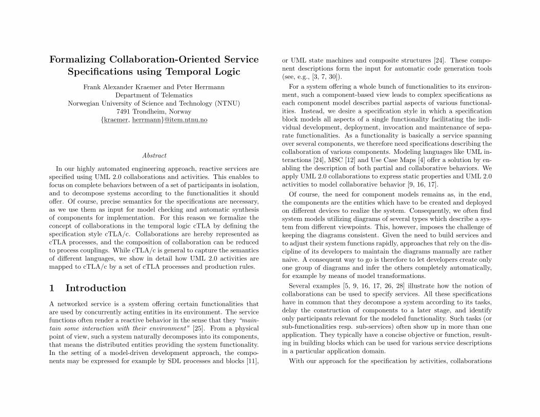
Figure 1: The SPACE Engineering Approach
and executable state machines (SPACE), we develop a tool-supportedprocess that analyzes and transforms collaborative service specificationsin a highly automated way [17]. The approach is outlined in Fig. 1. Of-ten, a new service can be composed from already existing collaborationpatterns that may be adapted to the operations and data types spe-cific for the application under construction. An engineer therefore mayconsider a library of reusable building blocks which are subsequentlycomposed obtaining a composite service specification. To come to anexecutable system, the service specifications in terms of UML 2.0 activ-ities and collaborations are then transformed into UML 2.0 componentsand state machines, as detailed in [19]. From this representation, codegeneration is quite straightforward, as for example explained in [20]. Inthis way, the engineer just works on the creation of the service specifica-tions, while the rest of the approach is automated, so that consistencyis ensured by construction. Tool support for the SPACE approach ex-ists in form of two integrated Eclipse-based tool sets [14]. Arctis offerssupport for collaborative service specifications, their analysis and trans-formation into executable state machines. These can then be furtheranalyzed by Ramses, which also offers code generators to create imple-mentations based on Java.
Of course, to guarantee the precise understanding of the models andthe correctness of the transformations, the approach requires formalreasoning on the semantics of the languages used, the transformationtools, and the consistency of building blocks and their composition.Temporal logic is a suitable instrument for that. In particular, theprinciple of superposition supported by cTLA [8, 10] makes it possible todescribe systems from different viewpoints by individual processes thatare superimposed (see Sect. 3.2). Therefore, the development approachin Fig. 1 is complemented by formal reasoning (shown on the left side).In a first step, we formalized the behavior of the state machines withcTLA/e [20]. This cTLA style defines a set of constraints for cTLAspecifications that directly reflect the special properties of the statemachines needed to enable the generation of efficiently executable code.Due to this foundation of the state machines, we can ensure that thegenerated program code is compliant with the behavior described in thestate machines (see [20]).
In this paper, we focus on the definition of cTLA/c, a style of cTLAthat allows us to formalize the collaborative service specifications givenby UML 2.0 activities. By expressing collaborations as cTLA processes,we can ensure that a composed service maintains the properties of theindividual collaborations it is composed from. The semantic definitionpresented here enables us to prove formally that the transformationfrom activities to state machines is correctness-preserving. As sketchedin [19], this corresponds to substitute that an activity modeled by thecTLA/c specification A is always transformed to a state machine de-scribed by cTLA/e model S which is a correct refinement of A (i.e.,S ⇒ A holds).
The semantic definition of collaborations and activities in form oftemporal logic is implemented as a transformation tool [29] which pro-duces TLA+ modules from activities. These modules may then be usedas input for the model checker TLC [32]. The tool also generates anumber of theorems, so that collaborations may be analyzed for moreadvanced properties than simple syntactic checks allow.
In Sect. 2, we introduce service specifications based on collaborationsand activities by means of an example. An introduction to generalcTLA in Sect. 3 is followed by the presentation of the specification stylecTLA/c in Sect. 4. Thereafter, Sect. 5 is devoted to the formal definition
awning
living room
lightlightsoundtemperature
locationaccessserverserver
gardenzonezone
Figure 2: Illustration for a system configuration
of the UML 2.0 activities used in our approach. For that, special cTLAspecification blocks to model the behavioral features of the activitynodes are used. In addition, we define a set of production rules guidingthe creation of the final cTLA/c specifications according to the nodesand edges of an activity. In Sect. 6, we discuss how these specificationsmodeling elementary service collaborations can be composed to specifyalso composite specifications and service descriptions that may handleseveral users and multiple sessions at a time.
2 Specifications in SPACE
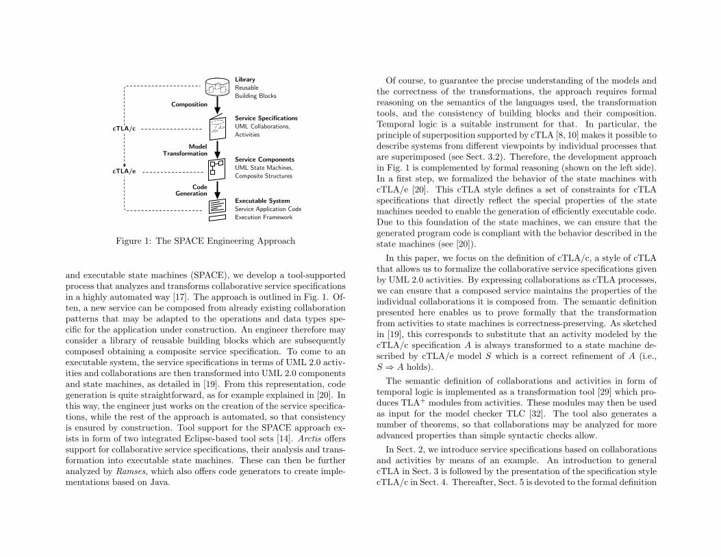
As an example, we consider a system for home automation, which allowsthe residents of a house to control various devices with their mobilephones. Devices may be heaters and volume controls, lights, motors ofawnings, or the intercom with the door bell. The house is organizedin zones covering different possibly overlapping areas. Each device isassigned to a zone manager, as illustrated in Fig. 2 with a zone for theliving room and one for the garden. To make the user interface easier,the control options offered by a mobile phone should depend on itscurrent location, so that one may adjust the room temperature of onlythe room one currently stays in, or roll out the awnings when one is onthe terrace. For this reason, we assume that the position of the phonescan be determined by a location server with sufficient accuracy (e.g., byequipping them with WLAN capabilities). Via this channel, the mobilephones may also communicate to the zone managers. In addition to thelocation server, an access server keeps record of the user authorizationsand access rights, for example, to grant guests and children only limitedcontrol.
Mobile Home Control
z: Zone Manager [1..*]
l: Location Server
a: Access Server
p: Phone [0..*]
h: Heater [0..*]
«system»
t: TemperatureUpdate
1
accessserver
serverlocation
phone
zonemanagerzonemanager
heaterz: ZoneSession
Figure 3: System collaboration
2.1 UML 2.0 Collaborations
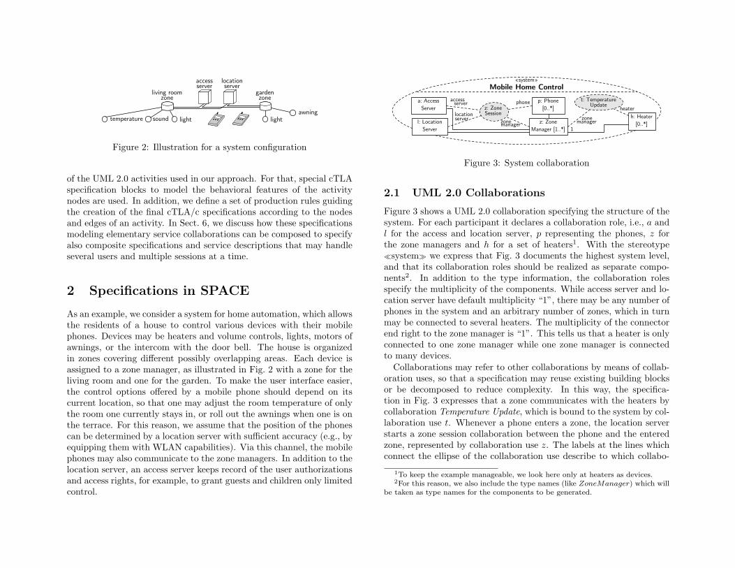
Figure 3 shows a UML 2.0 collaboration specifying the structure of thesystem. For each participant it declares a collaboration role, i.e., a andl for the access and location server, p representing the phones, z forthe zone managers and h for a set of heaters1. With the stereotype�system� we express that Fig. 3 documents the highest system level,and that its collaboration roles should be realized as separate compo-nents2. In addition to the type information, the collaboration rolesspecify the multiplicity of the components. While access server and lo-cation server have default multiplicity “1”, there may be any number ofphones in the system and an arbitrary number of zones, which in turnmay be connected to several heaters. The multiplicity of the connectorend right to the zone manager is “1”. This tells us that a heater is onlyconnected to one zone manager while one zone manager is connectedto many devices.
Collaborations may refer to other collaborations by means of collab-oration uses, so that a specification may reuse existing building blocksor be decomposed to reduce complexity. In this way, the specifica-tion in Fig. 3 expresses that a zone communicates with the heaters bycollaboration Temperature Update, which is bound to the system by col-laboration use t. Whenever a phone enters a zone, the location serverstarts a zone session collaboration between the phone and the enteredzone, represented by collaboration use z. The labels at the lines whichconnect the ellipse of the collaboration use describe to which collabo-
1To keep the example manageable, we look here only at heaters as devices.2For this reason, we also include the type names (like ZoneManager) which will
be taken as type names for the components to be generated.
heater
read valueelse
changed
zone managerTemperature Update
set value
update display
update device
i1
m1
t1
f1
d1
z1
z2e2
e0
e4e3
e6o1
e7
o2
e9e8
e5 e1
Figure 4: Activity describing the control of the temperature
ration roles of the referring collaboration the collaboration roles of thereferred collaboration are bound.
2.2 Activities for Elementary Collaborations
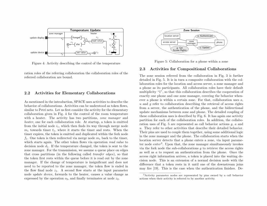
As mentioned in the introduction, SPACE uses activities to describe thebehavior of collaborations. Activities can be understood as token flows,similar to Petri nets. Let us first consider the activity for the elementarycollaboration given in Fig. 4 for the control of the room temperaturewith a heater. The activity has two partitions, zone manager andheater, one for each collaboration role. At startup, a token is emittedfrom the initial node i1, which then finds its way through merge nodem1 towards timer t1, where it starts the timer and rests. When thetimer expires, the token is emitted and duplicated within the fork nodef1. One token is then redirected via merge node m1 back to the timer,which starts again. The other token flows via operation read value todecision node d1. If the temperature changed, the token is sent to thezone manager. For the transmission, we assume a queue place on edgesthat cross partitions (in the following called transfer edges), so thatthe token first rests within the queue before it is read out by the zonemanager. If the change of temperature is insignificant and does notneed to be reported to the zone manager, the token flow is ended inthe flow final node z1. A second flow starts at the input parameternode update device, forwards to the heater, causes a value change asexpressed by the operation o2, and finally terminates at node z2.
location server
u: Update
Zone Session
a: Authenticate
g: GetAccess Rights
access server phonemanagerzone
Figure 5: Collaboration for a phone within a zone
2.3 Activities for Compositional Collaborations
The zone session referred from the collaboration in Fig. 3 is furtherdetailed in Fig. 5. It is in turn a composite collaboration with the col-laboration roles for the location and access server, a zone manager anda phone as its participants. All collaboration roles have their defaultmultiplicity “1”, so that this collaboration describes the cooperation ofexactly one phone and one zone manager, covering the behavior when-ever a phone is within a certain zone. For that, collaboration uses a,u and g refer to collaboration describing the retrieval of access rightsfrom a server, the authentication of the phone, and the bidirectionalupdate mechanisms between zone and phone. The detailed coupling ofthese collaboration uses is described by Fig. 6. It has again one activitypartition for each of the collaboration roles. In addition, the collabo-ration uses of Fig. 5 are represented as call behavior actions g, a andu. They refer to other activities that describe their detailed behavior.Their pins are used to couple them together, using some additional logicin the zone manager and the phone. The collaboration starts when thelocation server detects that a phone enters a zone, via input parame-ter node enter3. Upon that, the zone manager simultaneously invokesvia the fork node the sub-collaborations g to retrieve the access rightsas well as a to request an authentication from the phone. Once theaccess right information arrives, a token is placed into the waiting de-cision node. This is an extension of a normal decision node with thedifference that a token rests in it until one of the downstream joinsmay fire [19]. This is the case when the authentication finishes. De-
3Activity parameter nodes are represented by pins owned by a call behavioractions when their activity is referred to by another activity.
g: Get Access Rights
a: Authenticatefailed ok
computeoptions
registeroptions
registerphone
u: Update
zone manager
phone
access serverlocation server
Zone Session
removephone stop
update display
update device
enter
leave
update displayupdate device
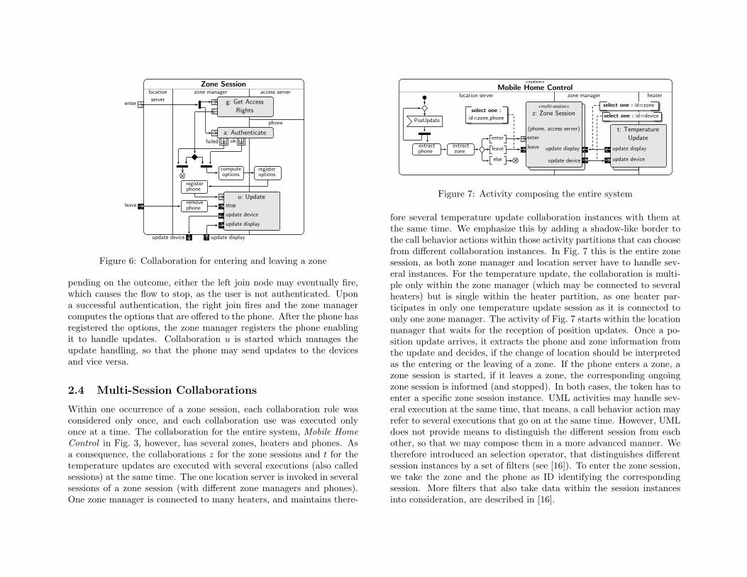
Figure 6: Collaboration for entering and leaving a zone
pending on the outcome, either the left join node may eventually fire,which causes the flow to stop, as the user is not authenticated. Upona successful authentication, the right join fires and the zone managercomputes the options that are offered to the phone. After the phone hasregistered the options, the zone manager registers the phone enablingit to handle updates. Collaboration u is started which manages theupdate handling, so that the phone may send updates to the devicesand vice versa.
2.4 Multi-Session Collaborations
Within one occurrence of a zone session, each collaboration role wasconsidered only once, and each collaboration use was executed onlyonce at a time. The collaboration for the entire system, Mobile HomeControl in Fig. 3, however, has several zones, heaters and phones. Asa consequence, the collaborations z for the zone sessions and t for thetemperature updates are executed with several executions (also calledsessions) at the same time. The one location server is invoked in severalsessions of a zone session (with different zone managers and phones).One zone manager is connected to many heaters, and maintains there-
z: Zone Session
PosUpdate
extractphone
extractzone
else
leave
enter
«multi-session»
z: Zone Session
(phone, access server)enter
leave
location serverMobile Home Control
zone manager
t: Temperature Update
heater
update device
update display update display
update device
select one : id=zone
select one : id=deviceselect one :
id=zone,phone
«system»
Figure 7: Activity composing the entire system
fore several temperature update collaboration instances with them atthe same time. We emphasize this by adding a shadow-like border tothe call behavior actions within those activity partitions that can choosefrom different collaboration instances. In Fig. 7 this is the entire zonesession, as both zone manager and location server have to handle sev-eral instances. For the temperature update, the collaboration is multi-ple only within the zone manager (which may be connected to severalheaters) but is single within the heater partition, as one heater par-ticipates in only one temperature update session as it is connected toonly one zone manager. The activity of Fig. 7 starts within the locationmanager that waits for the reception of position updates. Once a po-sition update arrives, it extracts the phone and zone information fromthe update and decides, if the change of location should be interpretedas the entering or the leaving of a zone. If the phone enters a zone, azone session is started, if it leaves a zone, the corresponding ongoingzone session is informed (and stopped). In both cases, the token has toenter a specific zone session instance. UML activities may handle sev-eral execution at the same time, that means, a call behavior action mayrefer to several executions that go on at the same time. However, UMLdoes not provide means to distinguish the different session from eachother, so that we may compose them in a more advanced manner. Wetherefore introduced an selection operator, that distinguishes differentsession instances by a set of filters (see [16]). To enter the zone session,we take the zone and the phone as ID identifying the correspondingsession. More filters that also take data within the session instancesinto consideration, are described in [16].
3 Temporal Logic and cTLA
Temporal logic enables to specify behavior which, according to Kurki-Suonio, is the “abstraction of reactive executions” [21]. Since networkedservices are reactive by nature, temporal logics are therefore suited tomodel the service behavior formally. One can distinguish temporallogics in linear time logics (LTL), which express behaviors by sets ofinfinite sequences of states, and in branching time logics (BTL) mod-eling state orders by tree structures. While the latter concept offers ahigher degree of expressiveness, LTLs often lead to easier understand-able specifications.
A well-known LTL is Leslie Lamport’s Temporal Logic of Actions(TLA, [23]) in which behavior is described by special state transitionsystems as well as fairness properties. The TLA coupling method bymeans of states common to several element specifications [1], however,makes it difficult to create constraint-oriented models in which not sin-gle physical components but properties reflecting partial system behav-ior spanning several components are specified [31]. As our collaboration-oriented models demand exactly this specification style, we use the com-positional Temporal Logic of Actions (cTLA, [8, 10]). This is a variantof TLA which provides couplings based on jointly executed transitionsenabling to glue interacting constraints nicely. Moreover, cTLA makesthe description of state transition systems in a process-like style pos-sible. A cTLA process can either be in a simple form, modeling thestate transition systems directly, or in a compositional form combiningseveral process instances which interact by the jointly fired transitions.In the following, we introduce both process types in detail.
3.1 Simple cTLA Processes
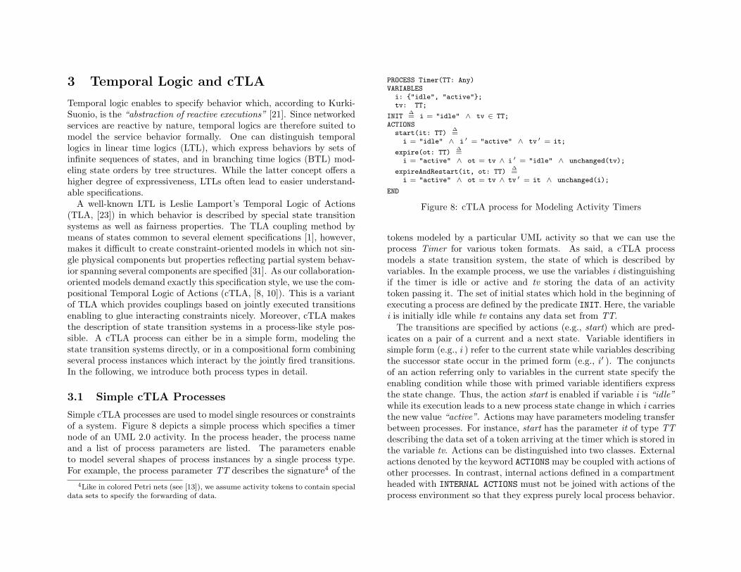
Simple cTLA processes are used to model single resources or constraintsof a system. Figure 8 depicts a simple process which specifies a timernode of an UML 2.0 activity. In the process header, the process nameand a list of process parameters are listed. The parameters enableto model several shapes of process instances by a single process type.For example, the process parameter TT describes the signature4 of the
4Like in colored Petri nets (see [13]), we assume activity tokens to contain specialdata sets to specify the forwarding of data.
PROCESS Timer(TT: Any)VARIABLES
i: {"idle", "active"};tv: TT;
INIT∆= i = "idle" ∧ tv ∈ TT;
ACTIONSstart(it: TT)
∆=
i = "idle" ∧ i ′ = "active" ∧ tv ′ = it;
expire(ot: TT)∆=
i = "active" ∧ ot = tv ∧ i ′ = "idle" ∧ unchanged(tv);
expireAndRestart(it, ot: TT)∆=
i = "active" ∧ ot = tv ∧ tv ′ = it ∧ unchanged(i);
END
Figure 8: cTLA process for Modeling Activity Timers
tokens modeled by a particular UML activity so that we can use theprocess Timer for various token formats. As said, a cTLA processmodels a state transition system, the state of which is described byvariables. In the example process, we use the variables i distinguishingif the timer is idle or active and tv storing the data of an activitytoken passing it. The set of initial states which hold in the beginning ofexecuting a process are defined by the predicate INIT. Here, the variablei is initially idle while tv contains any data set from TT.
The transitions are specified by actions (e.g., start) which are pred-icates on a pair of a current and a next state. Variable identifiers insimple form (e.g., i ) refer to the current state while variables describingthe successor state occur in the primed form (e.g., i′ ). The conjunctsof an action referring only to variables in the current state specify theenabling condition while those with primed variable identifiers expressthe state change. Thus, the action start is enabled if variable i is “idle”while its execution leads to a new process state change in which i carriesthe new value “active”. Actions may have parameters modeling transferbetween processes. For instance, start has the parameter it of type TTdescribing the data set of a token arriving at the timer which is stored inthe variable tv. Actions can be distinguished into two classes. Externalactions denoted by the keyword ACTIONS may be coupled with actions ofother processes. In contrast, internal actions defined in a compartmentheaded with INTERNAL ACTIONS must not be joined with actions of theprocess environment so that they express purely local process behavior.
In the process Timer we use only externally visible actions. Moreover,we may provide the actions with fairness assumptions guaranteeing alively behavior. Since we concentrate in this paper on safety aspectsonly, we do not discuss that in detail.
Formally, a cTLA process can be expressed as a TLA-formula, theso-called canonical formula C :
C , INIT ∧ �[∃it, ot ∈ TT : start(it) ∨ expire(ot) ∨expireAndRestart(it, ot)]〈i,tv〉
The conjunct at the left side of the formula states that the predicateINIT holds in the first state of every state sequence modeled by C.The conjunct on the right side starts with the temporal operator �(“always”) specifying that the expression right to it has to hold in allstates of all state sequences. The TLA expression [pp]〈i,tv〉 defines thateither the pair predicate pp holds or that a stuttering step5 takes placein which the annexed variable identifiers do not change their state (i.e.,i′ = i ∧ tv′ = tv holds). As pair predicate pp we listed the disjunctionof the process actions in which the process parameters are existentiallyquantified. This models that a state change in the process always corre-sponds to the execution of one of its actions using any action parametersof the set TT. Thus, the cTLA process specifies that the first processstate fulfills INIT and that all state changes follow the process actionsor are stuttering steps.
As outline above, cTLA processes are special TLA formulas which,however, follow certain constraints facilitating the cTLA-based actioncouplings. Mainly, a process action may access only variables of the pro-cess, it is defined in, and, like in DisCo [21], the actions can be uniquelyidentified which enables a reference of process actions in compositionaldescriptions. Some other conventions are necessary for guaranteeingliveness properties and are introduced in [8].
3.2 Compositional cTLA Processes
Compositional cTLA processes specify systems and subsystems as com-positions of simple cTLA process instances which cooperate by meansof synchronously executed process actions. Data transfer between the
5Stuttering steps are necessary for carrying out refinement proofs.
PROCESS TemperatureUpdate(TT: [[ temp: NATURALS, ANY ]] ;VT: [[ tsTemp, tsOldTemp: NATURALS; tsChg: BOOLEAN; ANY ]] )
CONSTANTSET = {"e1", "e2", "e3", "e4", "e5", "e6", "e7", "e8", "e9"};nv1 = [n ∈ VT × TT → VT
7→ [[ n.1 EXCEPT !.tsOldTemp = n.1.tsTempEXCEPT !.tsChg = n.1.tsTemp 6= n.1.tsOldTemp];
nt1 = [n ∈ TT × TT → TT 7→ [[ n.2 EXCEPT !.temp = n.1.tsTemp ]] ];nv2 = [n ∈ VT × TT → VT 7→ [[ n.1 EXCEPT !.tsTemp = n.2.temp ]] ];nt2 = [n ∈ TT × TT → TT 7→ n.2];gu1 = [n ∈ 1..2 × VT × TT → BOOLEAN
7→ IF n.1 = 1 THEN n.2.tsChg ELSE NOT n.2.tsChg ];PROCESSES
i1: Initial(TT);t1: Timer(TT);o1: Operation(nv1,nt1);d1: Decision(2,gu1);e6: Transfer(TT);e8: Transfer(TT);o2: Operation(nv2,nt2);
ACTIONSact3(it: TT; ot: [ET → TT], iv: VT, ov: [ET → VT],
is: TT, os: SUBSET TT, last: SUBSET ET)∆=
i1.start(it)∧ t1.start(it)∧ os = {}∧ ov = ["e0" 7→ iv, "e1" 7→ iv]∧ ot = ["e0" 7→ it, "e1" 7→ it]∧ last = {"e1"}∧ e6.Stutter ∧ e8.Stutter;. . .
END
Figure 9: cTLA Process describing the activity Temperature Update
simple processes is modeled by aligning the parameters of the coupledprocess actions. Since the variables of the simple processes are encapsu-lated and cannot be read or modified by other processes, a system stateis defined as the vector of the process variables. The system transi-tions are modeled by the synchronously executed process actions. Eachstateful simple process (i.e., each process in which variables are defined)contributes to a system action by either exactly one process action orby a stuttering step modeling concurrency as interleaving. In conse-quence, a system action is a conjunction of process actions and process
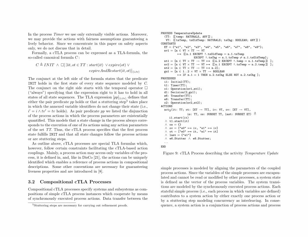
stuttering steps.Figure 9 models the cTLA specification of the UML activity Tem-
perature Update (see Fig. 4) as a compositional cTLA process with thesame name. The cTLA process is composed from the process instanceslisted in the section PROCESSES. For example, t1 is an instance of theprocess type Timer introduced above. The process parameter TT oft1 is instantiated with the process parameter TT defined as a processparameter in the compositional process. The external and internal sys-tem actions are specified in the blocks ACTIONS and INTERNAL ACTIONSas conjunctions of process actions and process stuttering steps. We de-picted the system action act3 modeling the flow from the initial UMLactivity node i1 to the timer t1. The action is a coupling of the actionsstart in both composed processes i1 and t1 while the processes e6 ande8 perform stuttering steps6.
Formally, a compositional cTLA process corresponds to the conjunc-tion of the canonical formulas of the composed simple processes and anadditional coupling constraint CC :
C , i1.C ∧ t1.C ∧ . . . ∧ o2.C ∧ CC
The coupling constraint defines the conjunction of the process actionsto system actions. Moreover, it defines some constraints on the processaction fairness properties which, together with the encapsulation of theprocess variables, guarantee that the cTLA composition principle fulfillsthe superposition property (see [8]). Superposition [2] ensures that eachproperty of a simple cTLA process holds also for each compositional oneincluding it. As mentioned in the introduction, this is an importantingredient to describe systems from different viewpoints since we candefine elementary service functions as separate simple cTLA processesand compose these easily to both collaborative and component-orientedsystem models. In addition, this property facilitates the formal proofsvastly that component models realize collaboration-based ones.
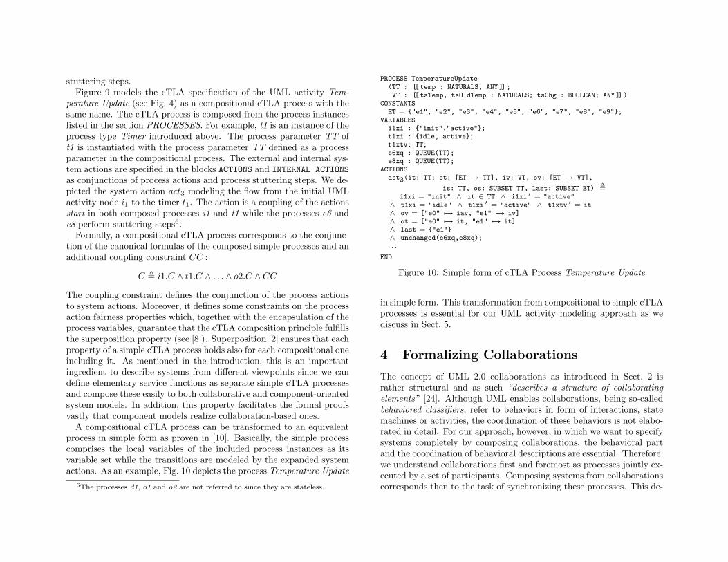
A compositional cTLA process can be transformed to an equivalentprocess in simple form as proven in [10]. Basically, the simple processcomprises the local variables of the included process instances as itsvariable set while the transitions are modeled by the expanded systemactions. As an example, Fig. 10 depicts the process Temperature Update
6The processes d1, o1 and o2 are not referred to since they are stateless.
PROCESS TemperatureUpdate(TT : [[ temp : NATURALS, ANY ]] ;VT : [[ tsTemp, tsOldTemp : NATURALS; tsChg : BOOLEAN; ANY ]] )
CONSTANTSET = {"e1", "e2", "e3", "e4", "e5", "e6", "e7", "e8", "e9"};
VARIABLESi1xi : {"init","active"};t1xi : {idle, active};t1xtv: TT;e6xq : QUEUE(TT);e8xq : QUEUE(TT);
ACTIONSact3(it: TT; ot: [ET → TT], iv: VT, ov: [ET → VT],
is: TT, os: SUBSET TT, last: SUBSET ET)∆=
i1xi = "init" ∧ it ∈ TT ∧ i1xi ′ = "active"∧ t1xi = "idle" ∧ t1xi ′ = "active" ∧ t1xtv ′ = it∧ ov = ["e0" 7→ iav, "e1" 7→ iv]∧ ot = ["e0" 7→ it, "e1" 7→ it]∧ last = {"e1"}∧ unchanged(e6xq,e8xq);. . .
END
Figure 10: Simple form of cTLA Process Temperature Update
in simple form. This transformation from compositional to simple cTLAprocesses is essential for our UML activity modeling approach as wediscuss in Sect. 5.
4 Formalizing Collaborations
The concept of UML 2.0 collaborations as introduced in Sect. 2 israther structural and as such “describes a structure of collaboratingelements” [24]. Although UML enables collaborations, being so-calledbehaviored classifiers, refer to behaviors in form of interactions, statemachines or activities, the coordination of these behaviors is not elabo-rated in detail. For our approach, however, in which we want to specifysystems completely by composing collaborations, the behavioral partand the coordination of behavioral descriptions are essential. Therefore,we understand collaborations first and foremost as processes jointly ex-ecuted by a set of participants. Composing systems from collaborationscorresponds then to the task of synchronizing these processes. This de-
p1p2
C a2
a1a3
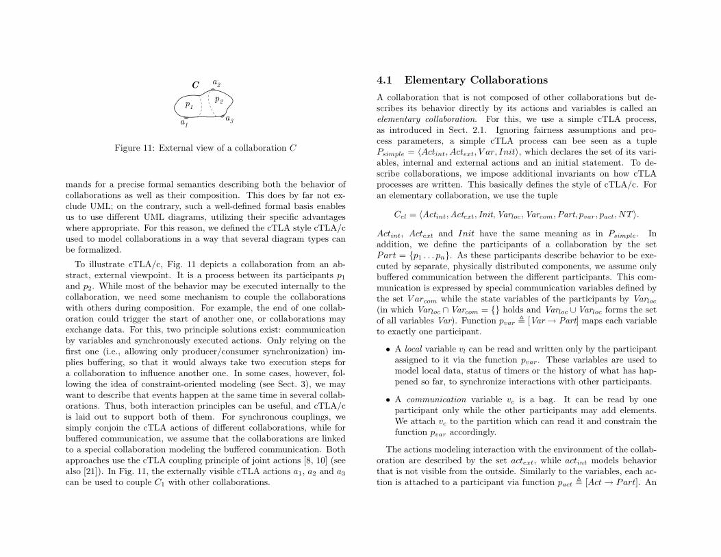
Figure 11: External view of a collaboration C
mands for a precise formal semantics describing both the behavior ofcollaborations as well as their composition. This does by far not ex-clude UML; on the contrary, such a well-defined formal basis enablesus to use different UML diagrams, utilizing their specific advantageswhere appropriate. For this reason, we defined the cTLA style cTLA/cused to model collaborations in a way that several diagram types canbe formalized.
To illustrate cTLA/c, Fig. 11 depicts a collaboration from an ab-stract, external viewpoint. It is a process between its participants p1
and p2. While most of the behavior may be executed internally to thecollaboration, we need some mechanism to couple the collaborationswith others during composition. For example, the end of one collab-oration could trigger the start of another one, or collaborations mayexchange data. For this, two principle solutions exist: communicationby variables and synchronously executed actions. Only relying on thefirst one (i.e., allowing only producer/consumer synchronization) im-plies buffering, so that it would always take two execution steps fora collaboration to influence another one. In some cases, however, fol-lowing the idea of constraint-oriented modeling (see Sect. 3), we maywant to describe that events happen at the same time in several collab-orations. Thus, both interaction principles can be useful, and cTLA/cis laid out to support both of them. For synchronous couplings, wesimply conjoin the cTLA actions of different collaborations, while forbuffered communication, we assume that the collaborations are linkedto a special collaboration modeling the buffered communication. Bothapproaches use the cTLA coupling principle of joint actions [8, 10] (seealso [21]). In Fig. 11, the externally visible cTLA actions a1, a2 and a3
can be used to couple C1 with other collaborations.
4.1 Elementary Collaborations
A collaboration that is not composed of other collaborations but de-scribes its behavior directly by its actions and variables is called anelementary collaboration. For this, we use a simple cTLA process,as introduced in Sect. 2.1. Ignoring fairness assumptions and pro-cess parameters, a simple cTLA process can bee seen as a tuplePsimple = 〈Actint, Actext, V ar, Init〉, which declares the set of its vari-ables, internal and external actions and an initial statement. To de-scribe collaborations, we impose additional invariants on how cTLAprocesses are written. This basically defines the style of cTLA/c. Foran elementary collaboration, we use the tuple
Cel = 〈Actint,Actext, Init,Varloc,Varcom,Part, pvar, pact, NT 〉.
Actint, Actext and Init have the same meaning as in Psimple. Inaddition, we define the participants of a collaboration by the setPart = {p1 . . . pn}. As these participants describe behavior to be exe-cuted by separate, physically distributed components, we assume onlybuffered communication between the different participants. This com-munication is expressed by special communication variables defined bythe set V arcom while the state variables of the participants by Varloc
(in which Varloc ∩Varcom = {} holds and Varloc ∪Varloc forms the setof all variables Var). Function pvar , [Var → Part] maps each variableto exactly one participant.
• A local variable vl can be read and written only by the participantassigned to it via the function pvar. These variables are used tomodel local data, status of timers or the history of what has hap-pened so far, to synchronize interactions with other participants.
• A communication variable vc is a bag. It can be read by oneparticipant only while the other participants may add elements.We attach vc to the partition which can read it and constrain thefunction pvar accordingly.
The actions modeling interaction with the environment of the collab-oration are described by the set actext, while actint models behaviorthat is not visible from the outside. Similarly to the variables, each ac-tion is attached to a participant via function pact , [Act → Part]. An
local variable
vnv2v1
ai
vn
a1
a2p1
a3
v3p2 v4
an internal action
participant
collaboration
a2
a1
variablecommunication
a3
Cel
a1 external action
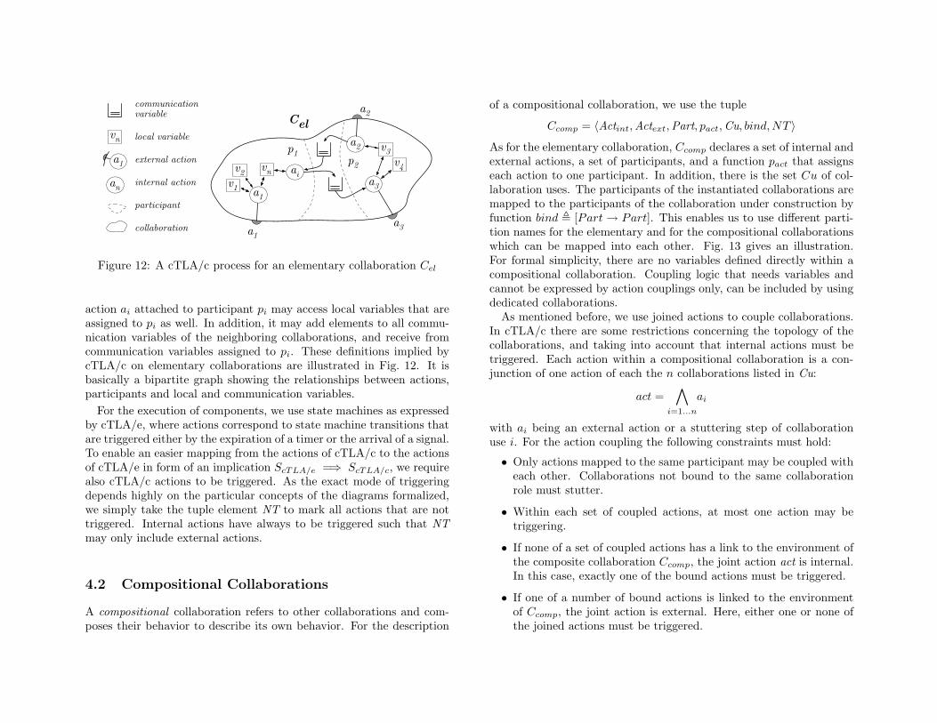
Figure 12: A cTLA/c process for an elementary collaboration Cel
action ai attached to participant pi may access local variables that areassigned to pi as well. In addition, it may add elements to all commu-nication variables of the neighboring collaborations, and receive fromcommunication variables assigned to pi. These definitions implied bycTLA/c on elementary collaborations are illustrated in Fig. 12. It isbasically a bipartite graph showing the relationships between actions,participants and local and communication variables.
For the execution of components, we use state machines as expressedby cTLA/e, where actions correspond to state machine transitions thatare triggered either by the expiration of a timer or the arrival of a signal.To enable an easier mapping from the actions of cTLA/c to the actionsof cTLA/e in form of an implication ScTLA/e =⇒ ScTLA/c, we requirealso cTLA/c actions to be triggered. As the exact mode of triggeringdepends highly on the particular concepts of the diagrams formalized,we simply take the tuple element NT to mark all actions that are nottriggered. Internal actions have always to be triggered such that NTmay only include external actions.
4.2 Compositional Collaborations
A compositional collaboration refers to other collaborations and com-poses their behavior to describe its own behavior. For the description
of a compositional collaboration, we use the tuple
Ccomp = 〈Actint,Actext,Part, pact,Cu, bind,NT 〉
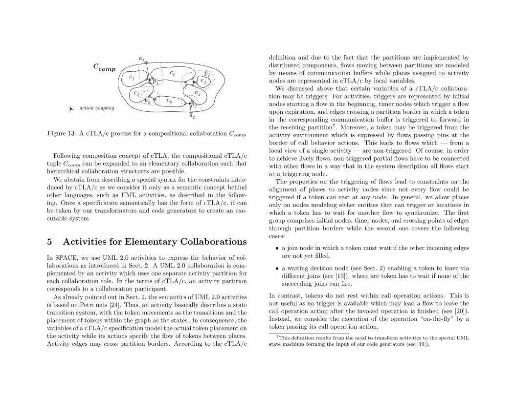
As for the elementary collaboration, Ccomp declares a set of internal andexternal actions, a set of participants, and a function pact that assignseach action to one participant. In addition, there is the set Cu of col-laboration uses. The participants of the instantiated collaborations aremapped to the participants of the collaboration under construction byfunction bind , [Part → Part]. This enables us to use different parti-tion names for the elementary and for the compositional collaborationswhich can be mapped into each other. Fig. 13 gives an illustration.For formal simplicity, there are no variables defined directly within acompositional collaboration. Coupling logic that needs variables andcannot be expressed by action couplings only, can be included by usingdedicated collaborations.
As mentioned before, we use joined actions to couple collaborations.In cTLA/c there are some restrictions concerning the topology of thecollaborations, and taking into account that internal actions must betriggered. Each action within a compositional collaboration is a con-junction of one action of each the n collaborations listed in Cu:
act =∧
i=1...n
ai
with ai being an external action or a stuttering step of collaborationuse i. For the action coupling the following constraints must hold:
• Only actions mapped to the same participant may be coupled witheach other. Collaborations not bound to the same collaborationrole must stutter.
• Within each set of coupled actions, at most one action may betriggering.
• If none of a set of coupled actions has a link to the environment ofthe composite collaboration Ccomp, the joint action act is internal.In this case, exactly one of the bound actions must be triggered.
• If one of a number of bound actions is linked to the environmentof Ccomp, the joint action is external. Here, either one or none ofthe joined actions must be triggered.
p1
p3
Ccomp
p2
c1c2
c3
c4 c5
p4
a1
a2
action couplingc6
Figure 13: A cTLA/c process for a compositional collaboration Ccomp
Following composition concept of cTLA, the compositional cTLA/ctuple Ccomp can be expanded to an elementary collaboration such thathierarchical collaboration structures are possible.
We abstain from describing a special syntax for the constraints intro-duced by cTLA/c as we consider it only as a semantic concept behindother languages, such as UML activities, as described in the follow-ing. Once a specification semantically has the form of cTLA/c, it canbe taken by our transformators and code generators to create an exe-cutable system.
5 Activities for Elementary Collaborations
In SPACE, we use UML 2.0 activities to express the behavior of col-laborations as introduced in Sect. 2. A UML 2.0 collaboration is com-plemented by an activity which uses one separate activity partition foreach collaboration role. In the terms of cTLA/c, an activity partitioncorresponds to a collaboration participant.
As already pointed out in Sect. 2, the semantics of UML 2.0 activitiesis based on Petri nets [24]. Thus, an activity basically describes a statetransition system, with the token movements as the transitions and theplacement of tokens within the graph as the states. In consequence, thevariables of a cTLA/c specification model the actual token placement onthe activity while its actions specify the flow of tokens between places.Activity edges may cross partition borders. According to the cTLA/c
definition and due to the fact that the partitions are implemented bydistributed components, flows moving between partitions are modeledby means of communication buffers while places assigned to activitynodes are represented in cTLA/c by local variables.
We discussed above that certain variables of a cTLA/c collabora-tion may be triggers. For activities, triggers are represented by initialnodes starting a flow in the beginning, timer nodes which trigger a flowupon expiration, and edges crossing a partition border in which a tokenin the corresponding communication buffer is triggered to forward inthe receiving partition7. Moreover, a token may be triggered from theactivity environment which is expressed by flows passing pins at theborder of call behavior actions. This leads to flows which — from alocal view of a single activity — are non-triggered. Of course, in orderto achieve lively flows, non-triggered partial flows have to be connectedwith other flows in a way that in the system description all flows startat a triggering node.
The properties on the triggering of flows lead to constraints on thealignment of places to activity nodes since not every flow could betriggered if a token can rest at any node. In general, we allow placesonly on nodes modeling either entities that can trigger or locations inwhich a token has to wait for another flow to synchronize. The firstgroup comprises initial nodes, timer nodes, and crossing points of edgesthrough partition borders while the second one covers the followingcases:
• a join node in which a token must wait if the other incoming edgesare not yet filled,
• a waiting decision node (see Sect. 2) enabling a token to leave viadifferent joins (see [19]), where are token has to wait if none of thesucceeding joins can fire.
In contrast, tokens do not rest within call operation actions. This isnot useful as no trigger is available which may lead a flow to leave thecall operation action after the invoked operation is finished (see [20]).Instead, we consider the execution of the operation “on-the-fly” by atoken passing its call operation action.
7This definition results from the need to transform activities to the special UMLstate machines forming the input of our code generators (see [19]).
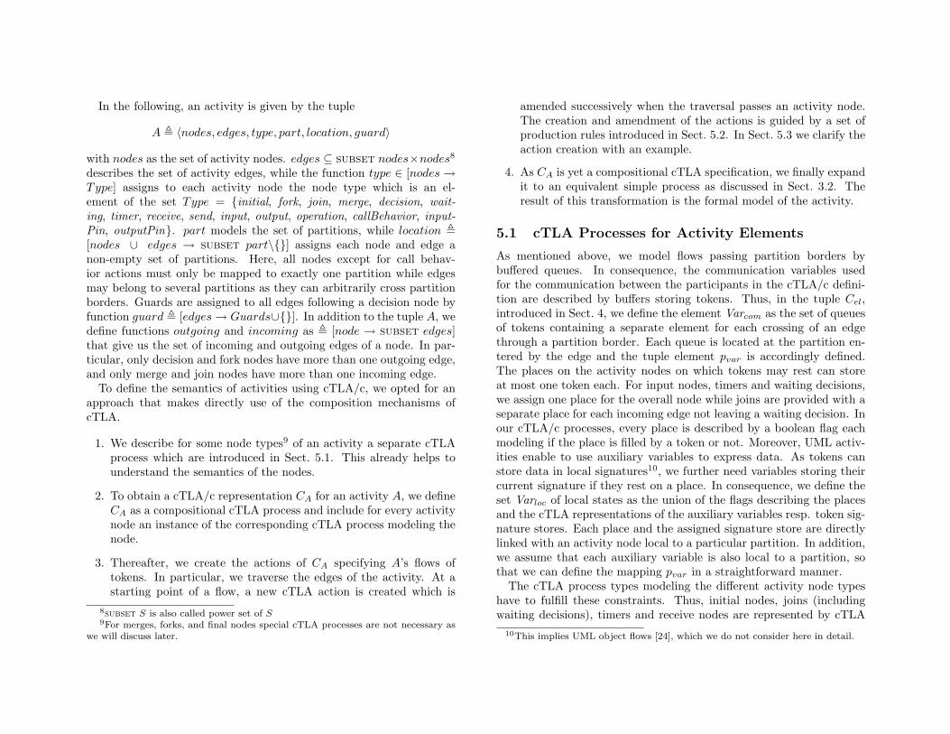
In the following, an activity is given by the tuple
A , 〈nodes, edges, type, part, location, guard〉
with nodes as the set of activity nodes. edges ⊆ subset nodes×nodes8
describes the set of activity edges, while the function type ∈ [nodes →Type] assigns to each activity node the node type which is an el-ement of the set Type = {initial, fork, join, merge, decision, wait-ing, timer, receive, send, input, output, operation, callBehavior, input-Pin, outputPin}. part models the set of partitions, while location ,[nodes ∪ edges → subset part\{}] assigns each node and edge anon-empty set of partitions. Here, all nodes except for call behav-ior actions must only be mapped to exactly one partition while edgesmay belong to several partitions as they can arbitrarily cross partitionborders. Guards are assigned to all edges following a decision node byfunction guard , [edges → Guards∪{}]. In addition to the tuple A, wedefine functions outgoing and incoming as , [node → subset edges]that give us the set of incoming and outgoing edges of a node. In par-ticular, only decision and fork nodes have more than one outgoing edge,and only merge and join nodes have more than one incoming edge.
To define the semantics of activities using cTLA/c, we opted for anapproach that makes directly use of the composition mechanisms ofcTLA.
1. We describe for some node types9 of an activity a separate cTLAprocess which are introduced in Sect. 5.1. This already helps tounderstand the semantics of the nodes.
2. To obtain a cTLA/c representation CA for an activity A, we defineCA as a compositional cTLA process and include for every activitynode an instance of the corresponding cTLA process modeling thenode.
3. Thereafter, we create the actions of CA specifying A’s flows oftokens. In particular, we traverse the edges of the activity. At astarting point of a flow, a new cTLA action is created which is
8subset S is also called power set of S9For merges, forks, and final nodes special cTLA processes are not necessary as
we will discuss later.
amended successively when the traversal passes an activity node.The creation and amendment of the actions is guided by a set ofproduction rules introduced in Sect. 5.2. In Sect. 5.3 we clarify theaction creation with an example.
4. As CA is yet a compositional cTLA specification, we finally expandit to an equivalent simple process as discussed in Sect. 3.2. Theresult of this transformation is the formal model of the activity.
5.1 cTLA Processes for Activity Elements
As mentioned above, we model flows passing partition borders bybuffered queues. In consequence, the communication variables usedfor the communication between the participants in the cTLA/c defini-tion are described by buffers storing tokens. Thus, in the tuple Cel,introduced in Sect. 4, we define the element Varcom as the set of queuesof tokens containing a separate element for each crossing of an edgethrough a partition border. Each queue is located at the partition en-tered by the edge and the tuple element pvar is accordingly defined.The places on the activity nodes on which tokens may rest can storeat most one token each. For input nodes, timers and waiting decisions,we assign one place for the overall node while joins are provided with aseparate place for each incoming edge not leaving a waiting decision. Inour cTLA/c processes, every place is described by a boolean flag eachmodeling if the place is filled by a token or not. Moreover, UML activ-ities enable to use auxiliary variables to express data. As tokens canstore data in local signatures10, we further need variables storing theircurrent signature if they rest on a place. In consequence, we define theset Varloc of local states as the union of the flags describing the placesand the cTLA representations of the auxiliary variables resp. token sig-nature stores. Each place and the assigned signature store are directlylinked with an activity node local to a particular partition. In addition,we assume that each auxiliary variable is also local to a partition, sothat we can define the mapping pvar in a straightforward manner.
The cTLA process types modeling the different activity node typeshave to fulfill these constraints. Thus, initial nodes, joins (includingwaiting decisions), timers and receive nodes are represented by cTLA
10This implies UML object flows [24], which we do not consider here in detail.
processes defining their places and token signature stores. The cTLAprocess modeling edges crossing partition borders defines meanwhilethe communication queue specifying the partition change. In addition,for each partition, we describe a cTLA process storing the local auxil-iary variables. Decision, sending and operation nodes are representedas stateless cTLA processes since that helps to encapsulate their spe-cific properties. For brevity, we introduce only the cTLA processes forinitial nodes, decisions, timers, operations as well as for transfer edgeswhich are necessary to understand the example sketched in Sect. 5.3. Acomplete documentation comprising the cTLA processes for all activitynodes is provided in [18].
Before discussing the cTLA processes in detail, we introduce somegeneric data types used as process parameters. VT describes the typesof all auxiliary variables in a partition. Here, we assume that a list ofvariables is expressed by a single record element. The signature set ofthe tokens is represented by the type TT, while ET is an enumerationproviding each edge in an activity a unique identifier.
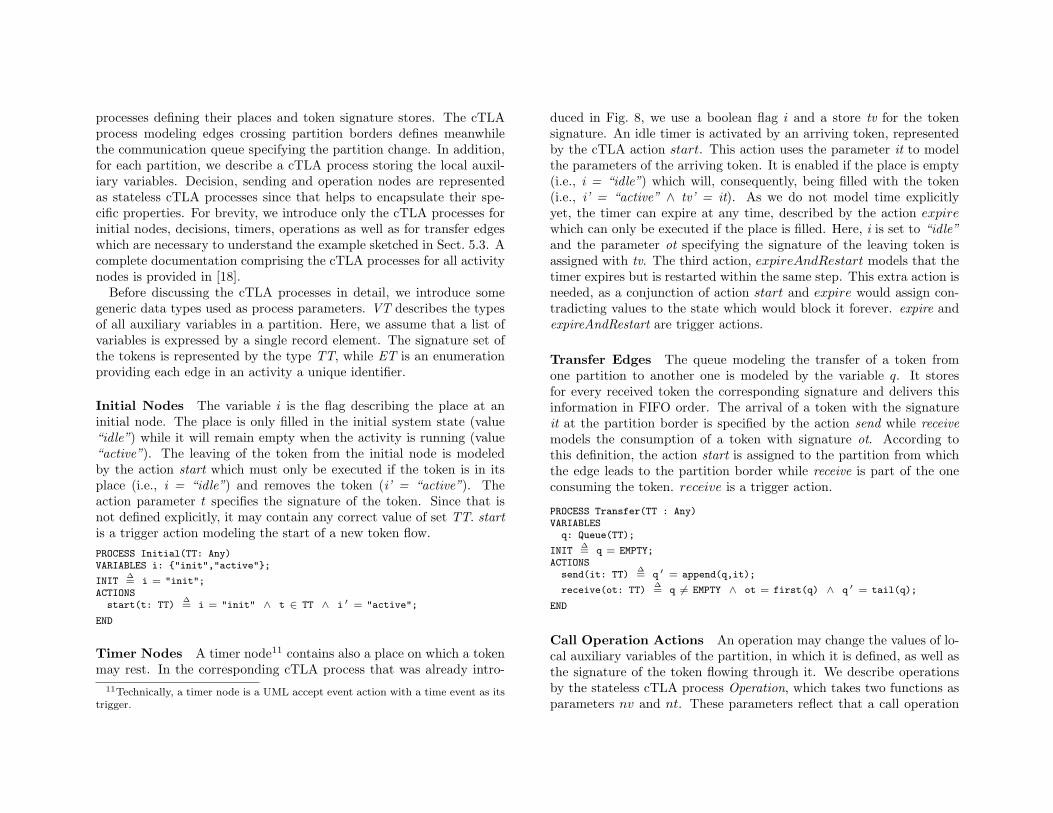
Initial Nodes The variable i is the flag describing the place at aninitial node. The place is only filled in the initial system state (value“idle”) while it will remain empty when the activity is running (value“active”). The leaving of the token from the initial node is modeledby the action start which must only be executed if the token is in itsplace (i.e., i = “idle”) and removes the token (i’ = “active”). Theaction parameter t specifies the signature of the token. Since that isnot defined explicitly, it may contain any correct value of set TT. startis a trigger action modeling the start of a new token flow.PROCESS Initial(TT: Any)VARIABLES i: {"init","active"};
INIT∆= i = "init";
ACTIONSstart(t: TT)
∆= i = "init" ∧ t ∈ TT ∧ i ′ = "active";
END
Timer Nodes A timer node11 contains also a place on which a tokenmay rest. In the corresponding cTLA process that was already intro-
11Technically, a timer node is a UML accept event action with a time event as itstrigger.
duced in Fig. 8, we use a boolean flag i and a store tv for the tokensignature. An idle timer is activated by an arriving token, representedby the cTLA action start. This action uses the parameter it to modelthe parameters of the arriving token. It is enabled if the place is empty(i.e., i = “idle”) which will, consequently, being filled with the token(i.e., i’ = “active” ∧ tv’ = it). As we do not model time explicitlyyet, the timer can expire at any time, described by the action expirewhich can only be executed if the place is filled. Here, i is set to “idle”and the parameter ot specifying the signature of the leaving token isassigned with tv. The third action, expireAndRestart models that thetimer expires but is restarted within the same step. This extra action isneeded, as a conjunction of action start and expire would assign con-tradicting values to the state which would block it forever. expire andexpireAndRestart are trigger actions.
Transfer Edges The queue modeling the transfer of a token fromone partition to another one is modeled by the variable q. It storesfor every received token the corresponding signature and delivers thisinformation in FIFO order. The arrival of a token with the signatureit at the partition border is specified by the action send while receivemodels the consumption of a token with signature ot. According tothis definition, the action start is assigned to the partition from whichthe edge leads to the partition border while receive is part of the oneconsuming the token. receive is a trigger action.
PROCESS Transfer(TT : Any)VARIABLES
q: Queue(TT);
INIT∆= q = EMPTY;
ACTIONSsend(it: TT)
∆= q ′ = append(q,it);
receive(ot: TT)∆= q 6= EMPTY ∧ ot = first(q) ∧ q ′ = tail(q);
END
Call Operation Actions An operation may change the values of lo-cal auxiliary variables of the partition, in which it is defined, as well asthe signature of the token flowing through it. We describe operationsby the stateless cTLA process Operation, which takes two functions asparameters nv and nt. These parameters reflect that a call operation
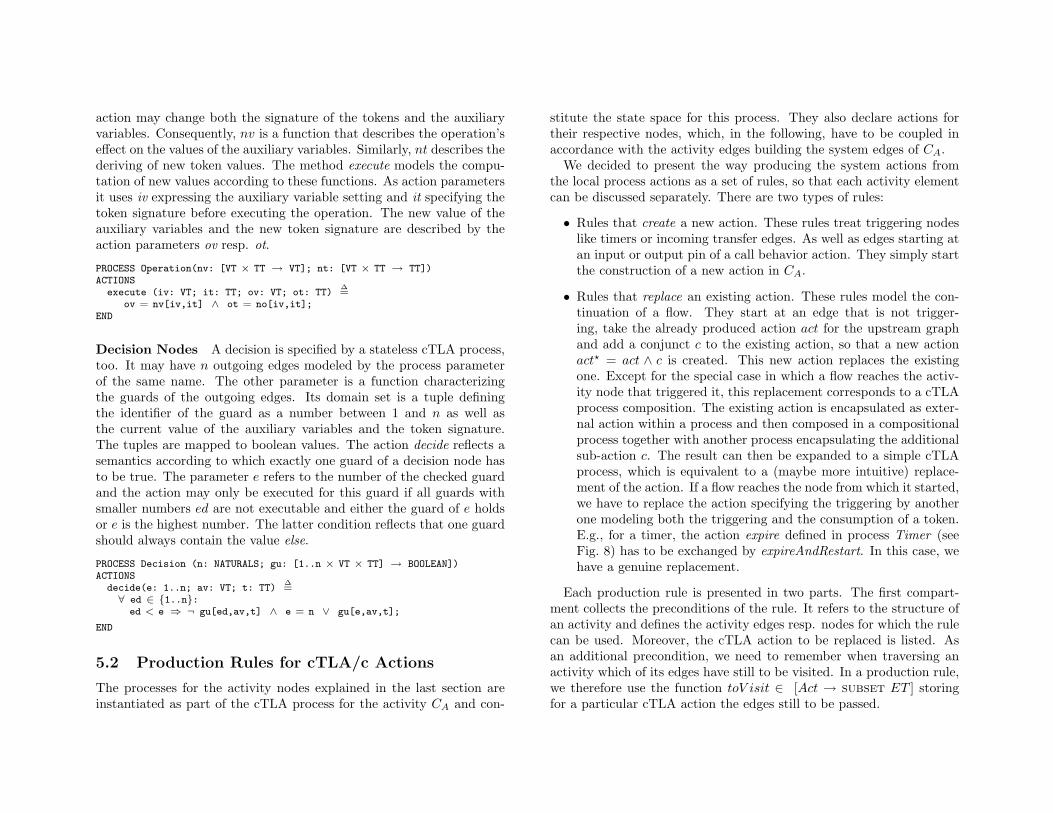
action may change both the signature of the tokens and the auxiliaryvariables. Consequently, nv is a function that describes the operation’seffect on the values of the auxiliary variables. Similarly, nt describes thederiving of new token values. The method execute models the compu-tation of new values according to these functions. As action parametersit uses iv expressing the auxiliary variable setting and it specifying thetoken signature before executing the operation. The new value of theauxiliary variables and the new token signature are described by theaction parameters ov resp. ot.
PROCESS Operation(nv: [VT × TT → VT]; nt: [VT × TT → TT])ACTIONS
execute (iv: VT; it: TT; ov: VT; ot: TT)∆=
ov = nv[iv,it] ∧ ot = no[iv,it];END
Decision Nodes A decision is specified by a stateless cTLA process,too. It may have n outgoing edges modeled by the process parameterof the same name. The other parameter is a function characterizingthe guards of the outgoing edges. Its domain set is a tuple definingthe identifier of the guard as a number between 1 and n as well asthe current value of the auxiliary variables and the token signature.The tuples are mapped to boolean values. The action decide reflects asemantics according to which exactly one guard of a decision node hasto be true. The parameter e refers to the number of the checked guardand the action may only be executed for this guard if all guards withsmaller numbers ed are not executable and either the guard of e holdsor e is the highest number. The latter condition reflects that one guardshould always contain the value else.
PROCESS Decision (n: NATURALS; gu: [1..n × VT × TT] → BOOLEAN])ACTIONS
decide(e: 1..n; av: VT; t: TT)∆=
∀ ed ∈ {1..n}:ed < e ⇒ ¬ gu[ed,av,t] ∧ e = n ∨ gu[e,av,t];
END
5.2 Production Rules for cTLA/c Actions
The processes for the activity nodes explained in the last section areinstantiated as part of the cTLA process for the activity CA and con-
stitute the state space for this process. They also declare actions fortheir respective nodes, which, in the following, have to be coupled inaccordance with the activity edges building the system edges of CA.
We decided to present the way producing the system actions fromthe local process actions as a set of rules, so that each activity elementcan be discussed separately. There are two types of rules:
• Rules that create a new action. These rules treat triggering nodeslike timers or incoming transfer edges. As well as edges starting atan input or output pin of a call behavior action. They simply startthe construction of a new action in CA.
• Rules that replace an existing action. These rules model the con-tinuation of a flow. They start at an edge that is not trigger-ing, take the already produced action act for the upstream graphand add a conjunct c to the existing action, so that a new actionact? = act ∧ c is created. This new action replaces the existingone. Except for the special case in which a flow reaches the activ-ity node that triggered it, this replacement corresponds to a cTLAprocess composition. The existing action is encapsulated as exter-nal action within a process and then composed in a compositionalprocess together with another process encapsulating the additionalsub-action c. The result can then be expanded to a simple cTLAprocess, which is equivalent to a (maybe more intuitive) replace-ment of the action. If a flow reaches the node from which it started,we have to replace the action specifying the triggering by anotherone modeling both the triggering and the consumption of a token.E.g., for a timer, the action expire defined in process Timer (seeFig. 8) has to be exchanged by expireAndRestart. In this case, wehave a genuine replacement.
Each production rule is presented in two parts. The first compart-ment collects the preconditions of the rule. It refers to the structure ofan activity and defines the activity edges resp. nodes for which the rulecan be used. Moreover, the cTLA action to be replaced is listed. Asan additional precondition, we need to remember when traversing anactivity which of its edges have still to be visited. In a production rule,we therefore use the function toV isit ∈ [Act → subset ET ] storingfor a particular cTLA action the edges still to be passed.
The second compartment shows the effect of the rule. It gives in-structions whether a new action should be created or an existing oneshould be replaced, and how the emerging action is constructed. Italso declares any changes to the function toV isit by updating the setof edges still to be visited for an action.
The construction of an action begins with one of the starting pointsof an activity, that means at initial nodes, at the exit of timers (whichmeans expiration), when an edge enters a partition, or when an exter-nal signal arrives. The rules Initial, TimerExpire, TransferEnterand Receive introduced below describe hereby how the action is writ-ten. Afterwards, other rules are applied to it guided by the nodes andedges that follow in the activity graph. A new action is created byadding conjuncts to the original one. In case we reach a decision orjoin node, the action created from the incoming graph is replaced byan entire set of actions. The construction of an action is finished whena new stable state is reached in the activity partition, that means thatwe either leave the partition, rest in a join or waiting decision, set atimer or reach a final or receiving node. Moreover, the leaving of a flowthrough the pin of a call behavior action is also a stopping point.
The actions under construction have the signature
act(it: TT; ot: [ET → TT]; iv: VT; ov: [ET → VT];is, os: SUBSET TT; last: SUBSET ET)
The parameter it specifies the value of the token when the flow starts.While the function ot describes the token signature after leaving a par-ticular edge. Similarly, parameters iv and ov describe the values ofthe local variables after the flow starts and after traversing a particularedge. Signals sent within an action are described with parameter os,and signals received by is. Parameter last keeps track of the edges in anaction after those the flow stops. This is needed to support the storageof the auxiliary variables discussed in Sect. 5.1.
In the following we will show the rules for initial nodes, merges, forks,timers, operations, transfer edges as well as decisions and flow finalnodes. The remaining rules are listed in [18].
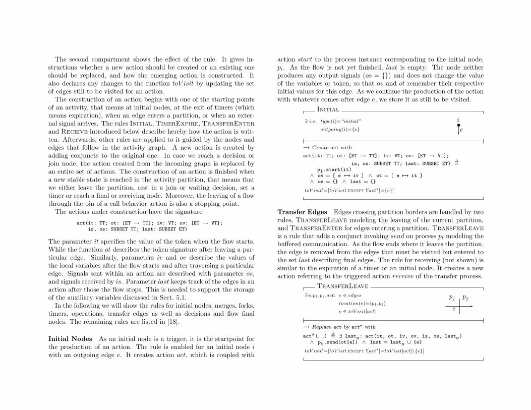
Initial Nodes As an initial node is a trigger, it is the startpoint forthe production of an action. The rule is enabled for an initial node iwith an outgoing edge e. It creates action act, which is coupled with
action start to the process instance corresponding to the initial node,pi. As the flow is not yet finished, last is empty. The node neitherproduces any output signals (os = {}) and does not change the valueof the variables or token, so that ov and ot remember their respectiveinitial values for this edge. As we continue the production of the actionwith whatever comes after edge e, we store it as still to be visited.
Initial
∃ i,e: type(i)=“initial”
outgoing(i)={e} ei
→ Create act with
act(it: TT; ot: [ET → TT]; iv: VT; ov: [ET → VT];
is, os: SUBSET TT; last: SUBSET ET)∆=
pi.start(it)∧ ov = [ e 7→ iv ] ∧ ot = [ e 7→ it ]∧ os = {} ∧ last = {}
toV isit′=[toV isit except ![act?]={e}]
Transfer Edges Edges crossing partition borders are handled by tworules, TransferLeave modeling the leaving of the current partition,and TransferEnter for edges entering a partition. TransferLeaveis a rule that adds a conjunct invoking send on process pt modeling thebuffered communication. As the flow ends where it leaves the partition,the edge is removed from the edges that must be visited but entered tothe set last describing final edges. The rule for receiving (not shown) issimilar to the expiration of a timer or an initial node. It creates a newaction referring to the triggered action receive of the transfer process.
TransferLeave
∃ e,p1,p2,act: e ∈ edges
location(e)=〈p1,p2〉
e ∈ toV isit[act]e
p1 p2
→ Replace act by act? with
act?(. . .)∆= ∃ lasto: act(it, ot, iv, ov, is, os, lasto)
∧ pt.send(ot[e]) ∧ last = lasto ∪ {e}
toV isit′=[toV isit except ![act?]=toV isit[act]\{e}]
Flow Final Nodes Flow final nodes simply terminate a token flow.The original action is finished by noting its last edge.
FlowFinal
∃ z,e,act: type(z)=“flowFinal”
incoming(z)={e}
e ∈ toV isit[act]
e
z
→ Replace act by act? with
act?(. . .)∆= ∃ lasto: act(it, ot, iv, ov, is, os, lasto)
∧ last = last ∪ {e}toV isit′=[toV isit except ![act?]=toV isit[act]\{e}]
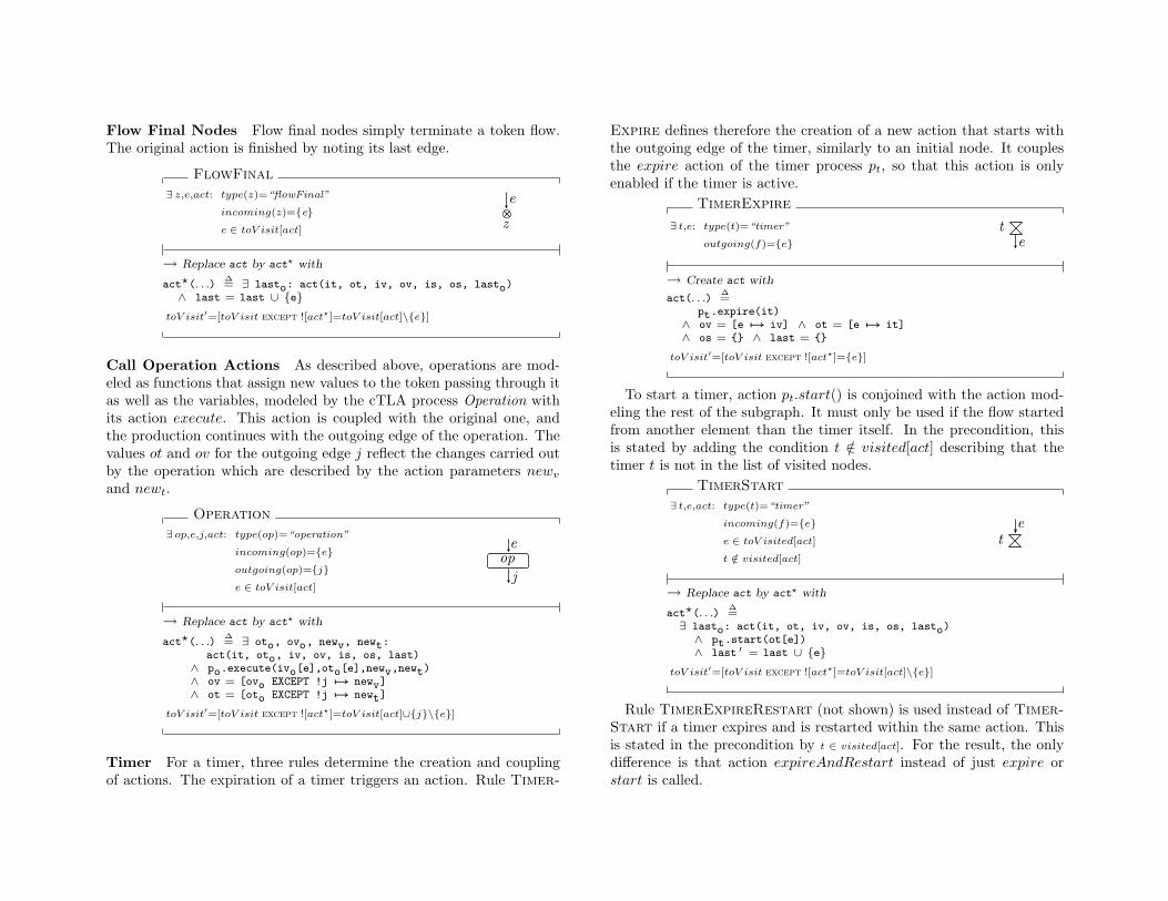
Call Operation Actions As described above, operations are mod-eled as functions that assign new values to the token passing through itas well as the variables, modeled by the cTLA process Operation withits action execute. This action is coupled with the original one, andthe production continues with the outgoing edge of the operation. Thevalues ot and ov for the outgoing edge j reflect the changes carried outby the operation which are described by the action parameters newv
and newt.
Operation
∃ op,e,j,act: type(op)=“operation”
incoming(op)={e}
outgoing(op)={j}
e ∈ toV isit[act]
ope
j
→ Replace act by act? with
act?(. . .)∆= ∃ oto, ovo, newv, newt:
act(it, oto, iv, ov, is, os, last)∧ po.execute(ivo[e],oto[e],newv,newt)∧ ov = [ovo EXCEPT !j 7→ newv]∧ ot = [oto EXCEPT !j 7→ newt]
toV isit′=[toV isit except ![act?]=toV isit[act]∪{j}\{e}]
Timer For a timer, three rules determine the creation and couplingof actions. The expiration of a timer triggers an action. Rule Timer-
Expire defines therefore the creation of a new action that starts withthe outgoing edge of the timer, similarly to an initial node. It couplesthe expire action of the timer process pt, so that this action is onlyenabled if the timer is active.
TimerExpire
∃ t,e: type(t)=“timer”
outgoing(f)={e} et
→ Create act with
act(. . .)∆=
pt.expire(it)∧ ov = [e 7→ iv] ∧ ot = [e 7→ it]∧ os = {} ∧ last = {}
toV isit′=[toV isit except ![act?]={e}]
To start a timer, action pt.start() is conjoined with the action mod-eling the rest of the subgraph. It must only be used if the flow startedfrom another element than the timer itself. In the precondition, thisis stated by adding the condition t /∈ visited[act] describing that thetimer t is not in the list of visited nodes.
TimerStart
∃ t,e,act: type(t)=“timer”
incoming(f)={e}
e ∈ toV isited[act]
t /∈ visited[act]
et
→ Replace act by act? with
act?(. . .)∆=
∃ lasto: act(it, ot, iv, ov, is, os, lasto)∧ pt.start(ot[e])∧ last ′ = last ∪ {e}
toV isit′=[toV isit except ![act?]=toV isit[act]\{e}]
Rule TimerExpireRestart (not shown) is used instead of Timer-Start if a timer expires and is restarted within the same action. Thisis stated in the precondition by t ∈ visited[act]. For the result, the onlydifference is that action expireAndRestart instead of just expire orstart is called.
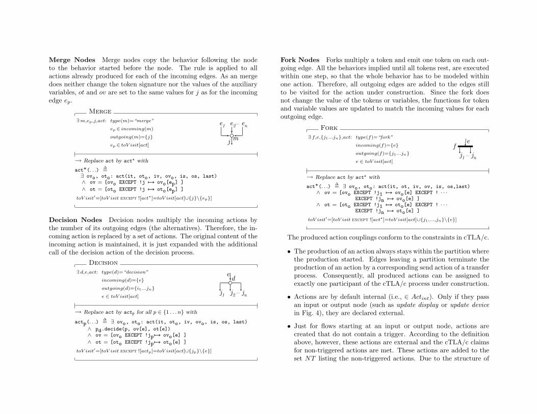
Merge Nodes Merge nodes copy the behavior following the nodeto the behavior started before the node. The rule is applied to allactions already produced for each of the incoming edges. As an mergedoes neither change the token signature nor the values of the auxiliaryvariables, ot and ov are set to the same values for j as for the incomingedge ep.
Merge
∃m,ep,j,act: type(m)=“merge”
ep ∈ incoming(m)
outgoing(m)={j}
ep ∈ toV isit[act]
e1 e2 en
mj
...
→ Replace act by act? with
act?(. . .)∆=
∃ ovo, oto: act(it, oto, iv, ovo, is, os, last)∧ ov = [ovo EXCEPT !j 7→ ovo[ep] ]
∧ ot = [oto EXCEPT !j 7→ oto[ep] ]
toV isit′=[toV isit except ![act?]=toV isit[act]∪{j}\{ep}]
Decision Nodes Decision nodes multiply the incoming actions bythe number of its outgoing edges (the alternatives). Therefore, the in-coming action is replaced by a set of actions. The original content of theincoming action is maintained, it is just expanded with the additionalcall of the decision action of the decision process.
Decision
∃ d,e,act: type(d)=“decision”
incoming(d)={e}
outgoing(d)={i1...jn}
e ∈ toV isit[act]j1 j2 jn
de
...
→ Replace act by actp for all p ∈ {1 . . . n} with
actp(. . .)∆= ∃ ovo, oto: act(it, oto, iv, ovo, is, os, last)
∧ pd.decide(p, ov[e], ot[e])∧ ov = [ovo EXCEPT !jp 7→ ovo[e] ]
∧ ot = [oto EXCEPT !jp 7→ oto[e] ]
toV isit′=[toV isit except ![actp]=toV isit[act]∪{jp}\{e}]
Fork Nodes Forks multiply a token and emit one token on each out-going edge. All the behaviors implied until all tokens rest, are executedwithin one step, so that the whole behavior has to be modeled withinone action. Therefore, all outgoing edges are added to the edges stillto be visited for the action under construction. Since the fork doesnot change the value of the tokens or variables, the functions for tokenand variable values are updated to match the incoming values for eachoutgoing edge.
Fork
∃ f,e,{j1...jn},act: type(f)=“fork”
incoming(f)={e}
outgoing(f)={j1...jn}
e ∈ toV isit[act]j1 jn...
ef
→ Replace act by act? with
act?(. . .)∆= ∃ ovo, oto: act(it, ot, iv, ov, is, os,last)
∧ ov = [ovo EXCEPT !j1 7→ ovo[e] EXCEPT ! · · ·EXCEPT !jn 7→ ovo[e] ]
∧ ot = [oto EXCEPT !j1 7→ oto[e] EXCEPT ! · · ·EXCEPT !jn 7→ oto[e] ]
toV isit′=[toV isit except ![act?]=toV isit[act]∪{j1,...,jn}\{e}]
The produced action couplings conform to the constraints in cTLA/c.
• The production of an action always stays within the partition wherethe production started. Edges leaving a partition terminate theproduction of an action by a corresponding send action of a transferprocess. Consequently, all produced actions can be assigned toexactly one participant of the cTLA/c process under construction.
• Actions are by default internal (i.e., ∈ Actint). Only if they passan input or output node (such as update display or update devicein Fig. 4), they are declared external.
• Just for flows starting at an input or output node, actions arecreated that do not contain a trigger. According to the definitionabove, however, these actions are external and the cTLA/c claimsfor non-triggered actions are met. These actions are added to theset NT listing the non-triggered actions. Due to the structure of
activities and the layout of the rules, a sub-graph corresponding toan action can never contain more than one trigger12.
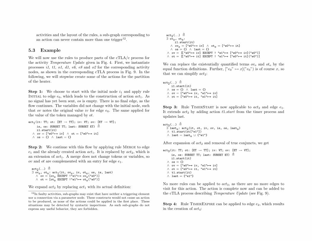
5.3 Example
We will now use the rules to produce parts of the cTLA/c process forthe activity Temperature Update given in Fig. 4. First, we instantiateprocesses i1, t1, o1, d1, e6, e8 and o2 for the corresponding activitynodes, as shown in the corresponding cTLA process in Fig. 9. In thefollowing, we will stepwise create some of the actions for the partitionof the heater.
Step 1: We choose to start with the initial node i1 and apply ruleInitial to edge e0, which leads to the construction of action act1. Asno signal has yet been sent, os is empty. There is no final edge, as theflow continues. The variables did not change with the initial node, suchthat ov notes the original value iv for edge e0. The same applied forthe value of the token managed by ot.
act1(it: TT; ot: [ET → TT]; iv: VT; ov: [ET → VT];
is, os: SUBSET TT; last: SUBSET ET)∆=
i1.start(it)∧ ov = ["e0"7→ iv] ∧ ot = ["e0"7→ it]∧ os = {} ∧ last = {}
Step 2: We continue with this flow by applying rule Merge to edgee1 and the already created action act1. It is replaced by act2, which isan extension of act1. A merge does not change tokens or variables, soov and ot are complemented with an entry for edge e1.
act2(. . .)∆=
∃ ovo, oto: act1(it, ovo, iv, oto, os, is, last)∧ ov = [ovo EXCEPT !"e1"7→ ovo("e0")]∧ ot = [oto EXCEPT !"e1"7→ oto("e0")]
We expand act2 by replacing act1 with its actual definition:12In faulty activities, sub-graphs may exist that have neither a triggering element
nor a connection via a parameter node. These constructs would not cause an actionto be produced, as none of the actions could be applied in the first place. Thesesituations may be detected by syntactic inspections. As such sub-graphs do notexpress any useful behavior, they are forbidden.
act2(. . .)∆=
∃ ovo, oto:i1.start(it)
∧ ovo = ["e0"7→ iv] ∧ oto = ["e0"7→ it]∧ os = {} ∧ last = {}
∧ ov = [[ "e0"7→ iv] EXCEPT ! "e1"7→ ["e0"7→ iv]("e0")]∧ ot = [[ "e0"7→ it] EXCEPT ! "e1"7→ ["e0"7→ it]("e0")]
We can replace the existentially quantified terms ovo and oto by theequal function definitions. Further, [”e0” 7→ x](”e0”) is of course x, sothat we can simplify act2:
act2(. . .)∆=
i1.start(it)∧ os = {} ∧ last = {}∧ ov = ["e0"7→ iv, "e1"7→ iv]∧ ot = ["e0"7→ it, "e1"7→ it]
Step 3: Rule TimerStart is now applicable to act2 and edge e1.It extends act2 by adding action t1.start from the timer process andupdates last.
act3(. . .)∆=
∃ lasto: act2(it, ot, iv, ov, is, os, lasto)∧ t1.start(ot["e1"])∧ last = lasto ∪ {"e1"}
After expansion of act2 and removal of true conjuncts, we get
act3(it: TT; ot: [ET → TT]; iv: VT; ov: [ET → VT];
is, os: SUBSET TT; last: SUBSET ET)∆=
i1.start(it)∧ os = {}∧ ov = ["e0"7→ iv, "e1"7→ iv]∧ ot = ["e0"7→ it, "e1"7→ it]∧ t1.start(it)∧ last = {"e1"}
No more rules can be applied to act3, as there are no more edges tovisit for this action. The action is complete now and can be added tothe cTLA process describing Temperature Update (see Fig. 9).
Step 4: Rule TimerExpire can be applied to edge e2, which resultsin the creation of act4:
act4(. . .)∆=
t1.expire(it)∧ ov = ["e2"7→ iv]∧ ot = ["e2"7→ it]∧ os = {} ∧ last = {}
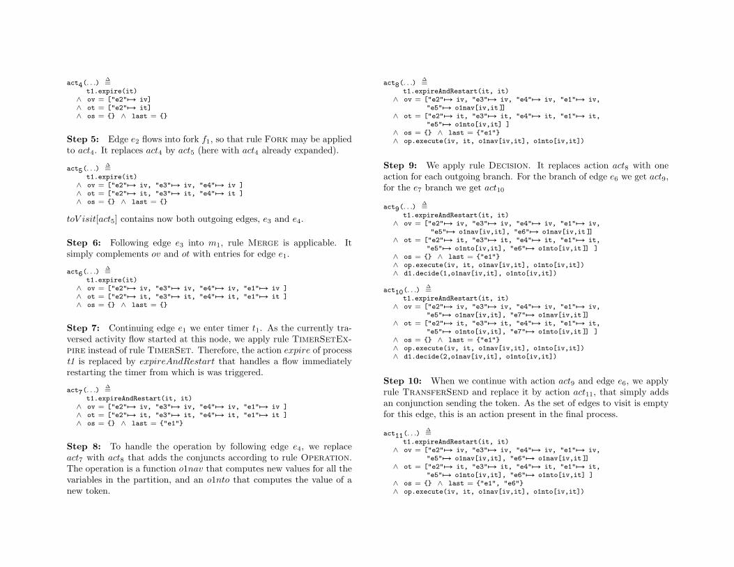
Step 5: Edge e2 flows into fork f1, so that rule Fork may be appliedto act4. It replaces act4 by act5 (here with act4 already expanded).
act5(. . .)∆=
t1.expire(it)∧ ov = ["e2"7→ iv, "e3"7→ iv, "e4"7→ iv ]∧ ot = ["e2"7→ it, "e3"7→ it, "e4"7→ it ]∧ os = {} ∧ last = {}
toV isit[act5] contains now both outgoing edges, e3 and e4.
Step 6: Following edge e3 into m1, rule Merge is applicable. Itsimply complements ov and ot with entries for edge e1.
act6(. . .)∆=
t1.expire(it)∧ ov = ["e2"7→ iv, "e3"7→ iv, "e4"7→ iv, "e1"7→ iv ]∧ ot = ["e2"7→ it, "e3"7→ it, "e4"7→ it, "e1"7→ it ]∧ os = {} ∧ last = {}
Step 7: Continuing edge e1 we enter timer t1. As the currently tra-versed activity flow started at this node, we apply rule TimerSetEx-pire instead of rule TimerSet. Therefore, the action expire of processt1 is replaced by expireAndRestart that handles a flow immediatelyrestarting the timer from which is was triggered.
act7(. . .)∆=
t1.expireAndRestart(it, it)∧ ov = ["e2"7→ iv, "e3"7→ iv, "e4"7→ iv, "e1"7→ iv ]∧ ot = ["e2"7→ it, "e3"7→ it, "e4"7→ it, "e1"7→ it ]∧ os = {} ∧ last = {"e1"}
Step 8: To handle the operation by following edge e4, we replaceact7 with act8 that adds the conjuncts according to rule Operation.The operation is a function o1nav that computes new values for all thevariables in the partition, and an o1nto that computes the value of anew token.
act8(. . .)∆=
t1.expireAndRestart(it, it)∧ ov = ["e2"7→ iv, "e3"7→ iv, "e4"7→ iv, "e1"7→ iv,
"e5"7→ o1nav[iv,it ]]∧ ot = ["e2"7→ it, "e3"7→ it, "e4"7→ it, "e1"7→ it,
"e5"7→ o1nto[iv,it] ]∧ os = {} ∧ last = {"e1"}∧ op.execute(iv, it, o1nav[iv,it], o1nto[iv,it])
Step 9: We apply rule Decision. It replaces action act8 with oneaction for each outgoing branch. For the branch of edge e6 we get act9,for the e7 branch we get act10
act9(. . .)∆=
t1.expireAndRestart(it, it)∧ ov = ["e2"7→ iv, "e3"7→ iv, "e4"7→ iv, "e1"7→ iv,
"e5"7→ o1nav[iv,it], "e6"7→ o1nav[iv,it ]]∧ ot = ["e2"7→ it, "e3"7→ it, "e4"7→ it, "e1"7→ it,
"e5"7→ o1nto[iv,it], "e6"7→ o1nto[iv,it ]] ]∧ os = {} ∧ last = {"e1"}∧ op.execute(iv, it, o1nav[iv,it], o1nto[iv,it])∧ d1.decide(1,o1nav[iv,it], o1nto[iv,it])
act10(. . .)∆=
t1.expireAndRestart(it, it)∧ ov = ["e2"7→ iv, "e3"7→ iv, "e4"7→ iv, "e1"7→ iv,
"e5"7→ o1nav[iv,it], "e7"7→ o1nav[iv,it ]]∧ ot = ["e2"7→ it, "e3"7→ it, "e4"7→ it, "e1"7→ it,
"e5"7→ o1nto[iv,it], "e7"7→ o1nto[iv,it ]] ]∧ os = {} ∧ last = {"e1"}∧ op.execute(iv, it, o1nav[iv,it], o1nto[iv,it])∧ d1.decide(2,o1nav[iv,it], o1nto[iv,it])
Step 10: When we continue with action act9 and edge e6, we applyrule TransferSend and replace it by action act11, that simply addsan conjunction sending the token. As the set of edges to visit is emptyfor this edge, this is an action present in the final process.
act11(. . .)∆=
t1.expireAndRestart(it, it)∧ ov = ["e2"7→ iv, "e3"7→ iv, "e4"7→ iv, "e1"7→ iv,
"e5"7→ o1nav[iv,it], "e6"7→ o1nav[iv,it ]]∧ ot = ["e2"7→ it, "e3"7→ it, "e4"7→ it, "e1"7→ it,
"e5"7→ o1nto[iv,it], "e6"7→ o1nto[iv,it] ]∧ os = {} ∧ last = {"e1", "e6"}∧ op.execute(iv, it, o1nav[iv,it], o1nto[iv,it])
i1
m1
t1
e0
e1
read valuechanged
t1
f1
d1
e2e4
e6o1
e5
m1
e3
e1
read valueelse t1
f1
d1
z1e2
e4
o1
e7 e5
m1
e3
e1
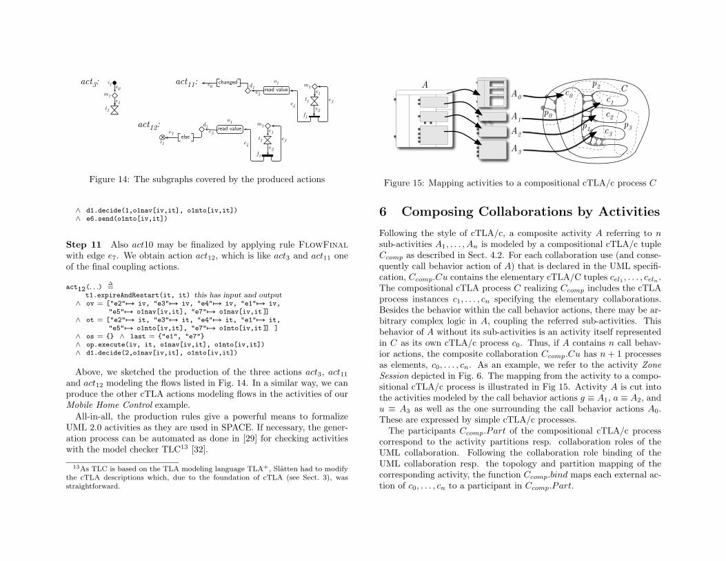
act3: act11:
act12:
Figure 14: The subgraphs covered by the produced actions
∧ d1.decide(1,o1nav[iv,it], o1nto[iv,it])∧ e6.send(o1nto[iv,it])
Step 11 Also act10 may be finalized by applying rule FlowFinalwith edge e7. We obtain action act12, which is like act3 and act11 oneof the final coupling actions.
act12(. . .)∆=
t1.expireAndRestart(it, it) this has input and output∧ ov = ["e2"7→ iv, "e3"7→ iv, "e4"7→ iv, "e1"7→ iv,
"e5"7→ o1nav[iv,it], "e7"7→ o1nav[iv,it ]]∧ ot = ["e2"7→ it, "e3"7→ it, "e4"7→ it, "e1"7→ it,
"e5"7→ o1nto[iv,it], "e7"7→ o1nto[iv,it ]] ]∧ os = {} ∧ last = {"e1", "e7"}∧ op.execute(iv, it, o1nav[iv,it], o1nto[iv,it])∧ d1.decide(2,o1nav[iv,it], o1nto[iv,it])
Above, we sketched the production of the three actions act3, act11and act12 modeling the flows listed in Fig. 14. In a similar way, we canproduce the other cTLA actions modeling flows in the activities of ourMobile Home Control example.
All-in-all, the production rules give a powerful means to formalizeUML 2.0 activities as they are used in SPACE. If necessary, the gener-ation process can be automated as done in [29] for checking activitieswith the model checker TLC13 [32].
13As TLC is based on the TLA modeling language TLA+, Slatten had to modifythe cTLA descriptions which, due to the foundation of cTLA (see Sect. 3), wasstraightforward.
AA0
A1A2A3
c0 c1c2c3
Cp2
p3p1
p0
Figure 15: Mapping activities to a compositional cTLA/c process C
6 Composing Collaborations by Activities
Following the style of cTLA/c, a composite activity A referring to nsub-activities A1, . . . , An is modeled by a compositional cTLA/c tupleCcomp as described in Sect. 4.2. For each collaboration use (and conse-quently call behavior action of A) that is declared in the UML specifi-cation, Ccomp.Cu contains the elementary cTLA/C tuples cel1 , . . . , celn .The compositional cTLA process C realizing Ccomp includes the cTLAprocess instances c1, . . . , cn specifying the elementary collaborations.Besides the behavior within the call behavior actions, there may be ar-bitrary complex logic in A, coupling the referred sub-activities. Thisbehavior of A without its sub-activities is an activity itself representedin C as its own cTLA/c process c0. Thus, if A contains n call behav-ior actions, the composite collaboration Ccomp.Cu has n + 1 processesas elements, c0, . . . , cn. As an example, we refer to the activity ZoneSession depicted in Fig. 6. The mapping from the activity to a compo-sitional cTLA/c process is illustrated in Fig 15. Activity A is cut intothe activities modeled by the call behavior actions g ≡ A1, a ≡ A2, andu ≡ A3 as well as the one surrounding the call behavior actions A0.These are expressed by simple cTLA/c processes.
The participants Ccomp.Part of the compositional cTLA/c processcorrespond to the activity partitions resp. collaboration roles of theUML collaboration. Following the collaboration role binding of theUML collaboration resp. the topology and partition mapping of thecorresponding activity, the function Ccomp.bind maps each external ac-tion of c0, . . . , cn to a participant in Ccomp.Part.
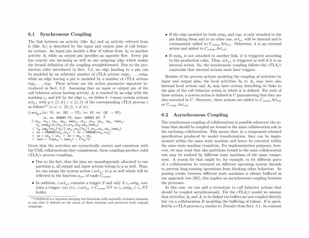
6.1 Synchronous Coupling
The link between an activity (like A0) and an activity referred fromit (like A1) is described by the input and output pins of call behav-ior actions. An input pin models a flow of tokens from A0 to anotheractivity Ai while an output pin specifies an opposite flow. Every pinhas exactly one incoming as well as one outgoing edge which makesthe formal definition of the coupling straightforward. Due to the pro-duction rules introduced in Sect. 5.2, an edge heading to a pin canbe modeled by an arbitrary number of cTLA actions outp1, . . . , outpk
while an edge leaving a pin is modeled by a number of cTLA actionsinp1, . . . , inpl. These actions use the action parameter signature in-troduced in Sect. 5.2. Assuming that an input or output pin of thecall behavior action hosting activity Ai is reached by an edge with themarking eo and left by the edge ei, we define k · l-many system actionsactq,r with q ∈ {1..k}, r ∈ {1..l} of the corresponding cTLA process cas follows14 (v, w ∈ {0, i}, v 6= w):C.actq,r(it: TT; ot: [ET → TT]; iv: VT; ov: [ET → VT];
is, os: SUBSET TT; last: SUBSET ET)∆=
∃ oto, ovo, iso, oso, lasto, oti, ovi, isi, osi, lasti:Cv.outpq(it,oto,iv,ovo,iso,oso,lasto)
∧ Cw.inpr(oto["eo"],oti,ovo["eo"],ovi,isi,osi,lasti)∧ ot = FMERGE(oto,oti) ∧ ov = FMERGE(ovo,ovi)∧ is = iso ∪ isi ∧ os = oso ∪ osi∧ last = (lasto ∪ lasti) \ {"eo"};
Given that the activities are syntactically correct and consistent withthe UML collaborations they complement, these couplings produce validcTLA/c process couplings.
• Due to the fact, that the pins are unambiguously allocated to onepartition p, all output and input actions belong to p as well. Thus,we can assign the system action c.actq,r to p as well which will bereflected in the function pact of tuple Ccomp.
• In addition, c.actq,r contains a trigger if and only if cv.outpq con-tains a trigger, too (i.e., c.actq,r ∈ Ccomp.NT ⇔ cv.outpq ∈ cv.NTholds).
14FMERGE is a function merging two functions with mutually exclusive domainsto one that is defined on the union of these domains and preserves both originalmappings.
• If the edge modeled by both outpq and inpr is only attached to thepin linking them and to no other one, actq,r will be internal and isconsequently added to Ccomp.Actint. Otherwise, it is an externalaction and added to Ccomp.Actext.
• If outpq is not attached to another link, it is triggered accordingto the production rules. Thus, actq,r is triggered as well if it is aninternal action. So, the synchronous coupling follows the cTLA/cconstraint that internal actions must have triggers.
Besides of the process actions modeling the coupling of activities byinput and output pins, the local activities A0 to An may have alsointernal local actions and A0 may have actions describing its links tothe pins of the call behavior action in which it is defined. For each ofthese actions, a system action is defined in C guaranteeing that they arealso executed in C. Moreover, these actions are added to Ccomp.Actint
or Ccomp.Actext.
6.2 Asynchronous Coupling
The synchronous coupling of collaborations is possible whenever the ac-tions that should be coupled are bound to the same collaboration role inthe enclosing collaboration. This means that, in a component-orientedspecification produced by model transformation, they can be imple-mented within the same state machine and hence be executed withinthe same state machine transition. For implementation purposes, how-ever, we may want that also partitions bound to the same collaborationrole may be realized by different state machines of the same compo-nent. A reason for that might be, for example, to let different partsof a collaboration be executed on different operating system threadsto prevent long-running operations from blocking other behaviors. Aspassing events between different state machines is always buffered inour approach (see [20]), this implies an asynchronous coupling betweenthe processes.
In this case, we can add a stereotype to call behavior actions thatshould be coupled asynchronously. For the cTLA/c model we assumethat activities A0 and Ai to be linked via buffers are not coupled directlybut via a collaboration B modeling the buffering of tokens. B is speci-fied by a cTLA process cB similar to Transfer from Sect. 5.1. In contrast
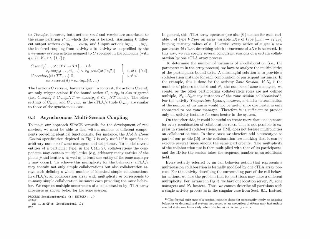
to Transfer, however, both actions send and receive are associated tothe same partition P in which the pin is located. Assuming k differ-ent output actions outp1, . . . , outpk and l input actions inp1, . . . , inpl,the buffered coupling from activity v to activity w is specified by thek+ l-many system actions assigned to C specified in the following (withq ∈ {1..k}, r ∈ {1..l}):
C.sendq(. . . , ot : [ET → TT ], . . .) ,cv.outpq(. . . , ot, . . .) ∧ cB .send(ot(”eo”))
C.receiver(it : TT, . . .) ,cB .receive(it) ∧ cw.inpr(it, . . .)
v, w ∈ {0, i},v 6= w
The l actions C.receiver have a trigger. In contrast, the actions C.sendq
are only trigger actions if the bound action Cv.outpq is also triggered(i.e., C.sendq ∈ Ccomp.NT ⇔ cv.outpq ∈ Celv .NT holds). The othersettings of Csendq
and Creceiverin the cTLA/c tuple Ccomp are similar
to those of the synchronous case.
6.3 Asynchronous Multi-Session Coupling
To make our approach SPACE versatile for the development of realservices, we must be able to deal with a number of different compo-nents providing identical functionality. For instance, the Mobile HomeControl specification depicted in Fig. 7 is only useful if it specifies anarbitrary number of zone managers and telephones. To model severalentities of a particular type, in the UML 2.0 collaborations the com-ponents may contain multiplicities (e.g, arbitrary many entities of thephone p and heater h as well as at least one entity of the zone managerz may occur). To achieve this multiplicity for the behaviors, cTLA/cmay contain not only simple collaborations but also collaboration ar-rays each defining a whole number of identical simple collaborations.In cTLA/c, an collaboration array with multiplicity m corresponds tom-many simple collaboration instances each providing the same behav-ior. We express multiple occurrences of a collaboration by cTLA arrayprocesses as shown below for the zone session:
PROCESS ZoneSessionMult (m: INTEGER; . . .)ARRAY
id: 1..m OF z: ZoneSession(. . .);END
In general, this cTLA array operator (see also [8]) defines for each vari-able v of type V Type an array variable zXv of type [1..m → vType]keeping m-many values of v. Likewise, every action of z gets a newparameter id : 1..m describing which occurrence of zXv is accessed. Inthis way, we can specify several concurrent sessions of a certain collab-oration by one cTLA array process.
To determine the number of instances of a collaboration (i.e., theparameter m in the array process), we have to analyze the multiplicitiesof the participants bound to it. A meaningful solution is to provide acollaboration instance for each combination of participant instances. Inthe example, this is done for the activity Zone Session. If Np is thenumber of phones modeled and Nz the number of zone managers, wecreate, as the other participating collaboration roles are not definedmultiple, Np · Nz-many instances of the zone session collaboration15.For the activity Temperature Update, however, a similar determinationof the number of instances would not be useful since one heater is onlyconnected to one zone manager. Therefore it is sufficient to provideonly on activity instance for each heater in the system.
On the other side, it could be useful to create more than one instancefor every combination of collaboration roles. This is not possible to ex-press in standard collaborations, as UML does not foresee multiplicitieson collaboration uses. In these cases we therefore add a stereotype aspart of our profile [15] to the collaboration use marking that it can beexecute several times among the same participants. The multiplicityof the collaboration use is then multiplied with that of its participants,and the ID for the session takes the sequence number as an additionalfield.
Every activity referred by an call behavior action that represents amulti-session collaboration is formally modeled by one cTLA array pro-cess. For the activity describing the surrounding part of the call behav-ior actions, we face the problem that its partitions may have a differentmultiplicity. For instance in Fig. 3, we have one location server, Nz zonemanagers and Nh heaters. Thus, we cannot describe all partitions witha single activity process as in the singular case from Sect. 6.1. Instead,
15The formal existence of a session instance does not necessarily imply an ongoingbehavior or demand real system resources, as an execution platform may instantiateneeded state machines only when the behavior actually starts.
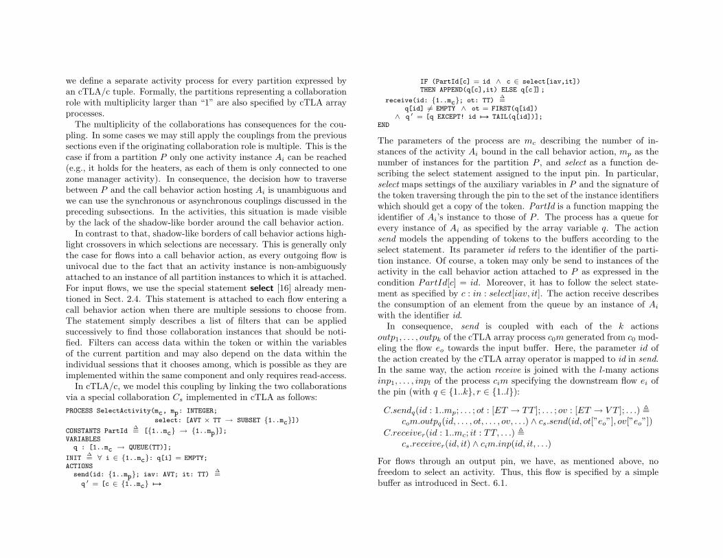
we define a separate activity process for every partition expressed byan cTLA/c tuple. Formally, the partitions representing a collaborationrole with multiplicity larger than “1” are also specified by cTLA arrayprocesses.
The multiplicity of the collaborations has consequences for the cou-pling. In some cases we may still apply the couplings from the previoussections even if the originating collaboration role is multiple. This is thecase if from a partition P only one activity instance Ai can be reached(e.g., it holds for the heaters, as each of them is only connected to onezone manager activity). In consequence, the decision how to traversebetween P and the call behavior action hosting Ai is unambiguous andwe can use the synchronous or asynchronous couplings discussed in thepreceding subsections. In the activities, this situation is made visibleby the lack of the shadow-like border around the call behavior action.
In contrast to that, shadow-like borders of call behavior actions high-light crossovers in which selections are necessary. This is generally onlythe case for flows into a call behavior action, as every outgoing flow isunivocal due to the fact that an activity instance is non-ambiguouslyattached to an instance of all partition instances to which it is attached.For input flows, we use the special statement select [16] already men-tioned in Sect. 2.4. This statement is attached to each flow entering acall behavior action when there are multiple sessions to choose from.The statement simply describes a list of filters that can be appliedsuccessively to find those collaboration instances that should be noti-fied. Filters can access data within the token or within the variablesof the current partition and may also depend on the data within theindividual sessions that it chooses among, which is possible as they areimplemented within the same component and only requires read-access.
In cTLA/c, we model this coupling by linking the two collaborationsvia a special collaboration Cs implemented in cTLA as follows:PROCESS SelectActivity(mc, mp: INTEGER;
select: [AVT × TT → SUBSET {1..mc}])CONSTANTS PartId
∆= [{1..mc} → {1..mp}];
VARIABLESq : [1..mc → QUEUE(TT)];
INIT∆= ∀ i ∈ {1..mc}: q[i] = EMPTY;
ACTIONSsend(id: {1..mp}; iav: AVT; it: TT)
∆=
q ′ = [c ∈ {1..mc} 7→
IF (PartId[c] = id ∧ c ∈ select[iav,it])THEN APPEND(q[c],it) ELSE q[c ]] ;
receive(id: {1..mc}; ot: TT)∆=
q[id] 6= EMPTY ∧ ot = FIRST(q[id])∧ q ′ = [q EXCEPT! id 7→ TAIL(q[id])];
END
The parameters of the process are mc describing the number of in-stances of the activity Ai bound in the call behavior action, mp as thenumber of instances for the partition P , and select as a function de-scribing the select statement assigned to the input pin. In particular,select maps settings of the auxiliary variables in P and the signature ofthe token traversing through the pin to the set of the instance identifierswhich should get a copy of the token. PartId is a function mapping theidentifier of Ai’s instance to those of P . The process has a queue forevery instance of Ai as specified by the array variable q. The actionsend models the appending of tokens to the buffers according to theselect statement. Its parameter id refers to the identifier of the parti-tion instance. Of course, a token may only be send to instances of theactivity in the call behavior action attached to P as expressed in thecondition PartId[c] = id. Moreover, it has to follow the select state-ment as specified by c : in : select[iav, it]. The action receive describesthe consumption of an element from the queue by an instance of Ai
with the identifier id.In consequence, send is coupled with each of the k actions
outp1, . . . , outpk of the cTLA array process c0m generated from c0 mod-eling the flow eo towards the input buffer. Here, the parameter id ofthe action created by the cTLA array operator is mapped to id in send.In the same way, the action receive is joined with the l-many actionsinp1, . . . , inpl of the process cim specifying the downstream flow ei ofthe pin (with q ∈ {1..k}, r ∈ {1..l}):
C.sendq(id : 1..mp; . . . ; ot : [ET → TT ]; . . . ; ov : [ET → V T ]; . . .) ,com.outpq(id, . . . , ot, . . . , ov, . . .) ∧ cs.send(id, ot[”eo”], ov[”eo”])
C.receiver(id : 1..mc; it : TT, . . .) ,cs.receiver(id, it) ∧ cim.inp(id, it, . . .)
For flows through an output pin, we have, as mentioned above, nofreedom to select an activity. Thus, this flow is specified by a simplebuffer as introduced in Sect. 6.1.
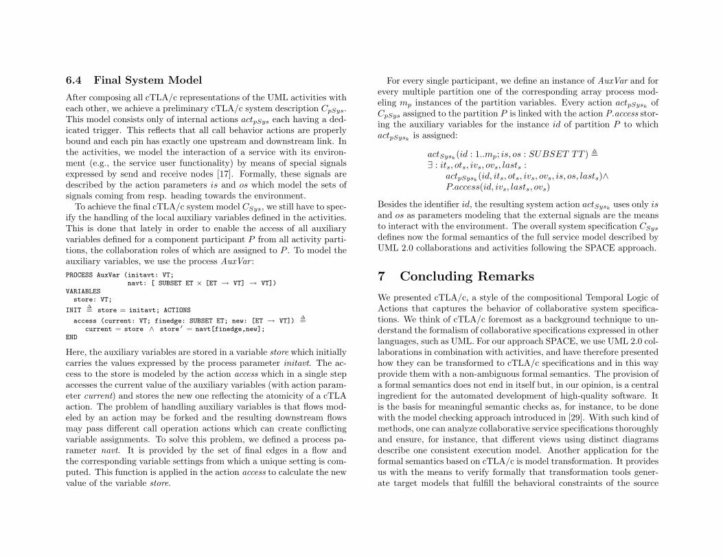
6.4 Final System Model
After composing all cTLA/c representations of the UML activities witheach other, we achieve a preliminary cTLA/c system description CpSys.This model consists only of internal actions actpSys each having a ded-icated trigger. This reflects that all call behavior actions are properlybound and each pin has exactly one upstream and downstream link. Inthe activities, we model the interaction of a service with its environ-ment (e.g., the service user functionality) by means of special signalsexpressed by send and receive nodes [17]. Formally, these signals aredescribed by the action parameters is and os which model the sets ofsignals coming from resp. heading towards the environment.
To achieve the final cTLA/c system model CSys, we still have to spec-ify the handling of the local auxiliary variables defined in the activities.This is done that lately in order to enable the access of all auxiliaryvariables defined for a component participant P from all activity parti-tions, the collaboration roles of which are assigned to P . To model theauxiliary variables, we use the process AuxVar :PROCESS AuxVar (initavt: VT;
navt: [ SUBSET ET × [ET → VT] → VT])VARIABLES
store: VT;
INIT∆= store = initavt; ACTIONS
access (current: VT; finedge: SUBSET ET; new: [ET → VT])∆=
current = store ∧ store ′ = navt[finedge,new];END
Here, the auxiliary variables are stored in a variable store which initiallycarries the values expressed by the process parameter initavt. The ac-cess to the store is modeled by the action access which in a single stepaccesses the current value of the auxiliary variables (with action param-eter current) and stores the new one reflecting the atomicity of a cTLAaction. The problem of handling auxiliary variables is that flows mod-eled by an action may be forked and the resulting downstream flowsmay pass different call operation actions which can create conflictingvariable assignments. To solve this problem, we defined a process pa-rameter navt. It is provided by the set of final edges in a flow andthe corresponding variable settings from which a unique setting is com-puted. This function is applied in the action access to calculate the newvalue of the variable store.
For every single participant, we define an instance of AuxVar and forevery multiple partition one of the corresponding array process mod-eling mp instances of the partition variables. Every action actpSysk
ofCpSys assigned to the partition P is linked with the action P.access stor-ing the auxiliary variables for the instance id of partition P to whichactpSysk
is assigned:
actSysk(id : 1..mp; is, os : SUBSET TT ) ,
∃ : its, ots, ivs, ovs, lasts :actpSysk
(id, its, ots, ivs, ovs, is, os, lasts)∧P.access(id, ivs, lasts, ovs)
Besides the identifier id, the resulting system action actSyskuses only is
and os as parameters modeling that the external signals are the meansto interact with the environment. The overall system specification CSys
defines now the formal semantics of the full service model described byUML 2.0 collaborations and activities following the SPACE approach.
7 Concluding Remarks
We presented cTLA/c, a style of the compositional Temporal Logic ofActions that captures the behavior of collaborative system specifica-tions. We think of cTLA/c foremost as a background technique to un-derstand the formalism of collaborative specifications expressed in otherlanguages, such as UML. For our approach SPACE, we use UML 2.0 col-laborations in combination with activities, and have therefore presentedhow they can be transformed to cTLA/c specifications and in this wayprovide them with a non-ambiguous formal semantics. The provision ofa formal semantics does not end in itself but, in our opinion, is a centralingredient for the automated development of high-quality software. Itis the basis for meaningful semantic checks as, for instance, to be donewith the model checking approach introduced in [29]. With such kind ofmethods, one can analyze collaborative service specifications thoroughlyand ensure, for instance, that different views using distinct diagramsdescribe one consistent execution model. Another application for theformal semantics based on cTLA/c is model transformation. It providesus with the means to verify formally that transformation tools gener-ate target models that fulfill the behavioral constraints of the source
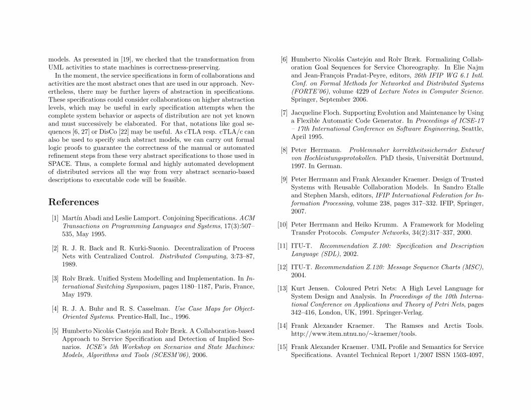
models. As presented in [19], we checked that the transformation fromUML activities to state machines is correctness-preserving.
In the moment, the service specifications in form of collaborations andactivities are the most abstract ones that are used in our approach. Nev-ertheless, there may be further layers of abstraction in specifications.These specifications could consider collaborations on higher abstractionlevels, which may be useful in early specification attempts when thecomplete system behavior or aspects of distribution are not yet knownand must successively be elaborated. For that, notations like goal se-quences [6, 27] or DisCo [22] may be useful. As cTLA resp. cTLA/c canalso be used to specify such abstract models, we can carry out formallogic proofs to guarantee the correctness of the manual or automatedrefinement steps from these very abstract specifications to those used inSPACE. Thus, a complete formal and highly automated developmentof distributed services all the way from very abstract scenario-baseddescriptions to executable code will be feasible.
References
[1] Martın Abadi and Leslie Lamport. Conjoining Specifications. ACMTransactions on Programming Languages and Systems, 17(3):507–535, May 1995.
[2] R. J. R. Back and R. Kurki-Suonio. Decentralization of ProcessNets with Centralized Control. Distributed Computing, 3:73–87,1989.
[3] Rolv Bræk. Unified System Modelling and Implementation. In In-ternational Switching Symposium, pages 1180–1187, Paris, France,May 1979.
[4] R. J. A. Buhr and R. S. Casselman. Use Case Maps for Object-Oriented Systems. Prentice-Hall, Inc., 1996.
[5] Humberto Nicolas Castejon and Rolv Bræk. A Collaboration-basedApproach to Service Specification and Detection of Implied Sce-narios. ICSE’s 5th Workshop on Scenarios and State Machines:Models, Algorithms and Tools (SCESM’06), 2006.
[6] Humberto Nicolas Castejon and Rolv Bræk. Formalizing Collab-oration Goal Sequences for Service Choreography. In Elie Najmand Jean-Francois Pradat-Peyre, editors, 26th IFIP WG 6.1 Intl.Conf. on Formal Methods for Networked and Distributed Systems(FORTE’06), volume 4229 of Lecture Notes in Computer Science.Springer, September 2006.
[7] Jacqueline Floch. Supporting Evolution and Maintenance by Usinga Flexible Automatic Code Generator. In Proceedings of ICSE-17– 17th International Conference on Software Engineering, Seattle,April 1995.
[8] Peter Herrmann. Problemnaher korrektheitssichernder Entwurfvon Hochleistungsprotokollen. PhD thesis, Universitat Dortmund,1997. In German.
[9] Peter Herrmann and Frank Alexander Kraemer. Design of TrustedSystems with Reusable Collaboration Models. In Sandro Etalleand Stephen Marsh, editors, IFIP International Federation for In-formation Processing, volume 238, pages 317–332. IFIP, Springer,2007.
[10] Peter Herrmann and Heiko Krumm. A Framework for ModelingTransfer Protocols. Computer Networks, 34(2):317–337, 2000.
[11] ITU-T. Recommendation Z.100: Specification and DescriptionLanguage (SDL), 2002.
[12] ITU-T. Recommendation Z.120: Message Sequence Charts (MSC),2004.
[13] Kurt Jensen. Coloured Petri Nets: A High Level Language forSystem Design and Analysis. In Proceedings of the 10th Interna-tional Conference on Applications and Theory of Petri Nets, pages342–416, London, UK, 1991. Springer-Verlag.
[14] Frank Alexander Kraemer. The Ramses and Arctis Tools.http://www.item.ntnu.no/∼kraemer/tools.
[15] Frank Alexander Kraemer. UML Profile and Semantics for ServiceSpecifications. Avantel Technical Report 1/2007 ISSN 1503-4097,
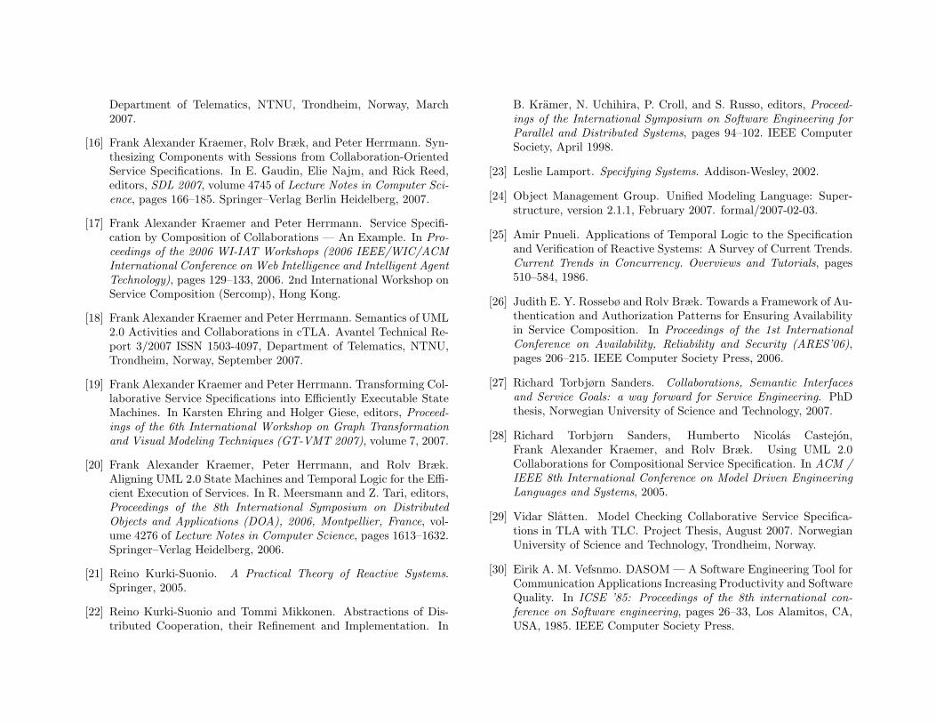
Department of Telematics, NTNU, Trondheim, Norway, March2007.
[16] Frank Alexander Kraemer, Rolv Bræk, and Peter Herrmann. Syn-thesizing Components with Sessions from Collaboration-OrientedService Specifications. In E. Gaudin, Elie Najm, and Rick Reed,editors, SDL 2007, volume 4745 of Lecture Notes in Computer Sci-ence, pages 166–185. Springer–Verlag Berlin Heidelberg, 2007.
[17] Frank Alexander Kraemer and Peter Herrmann. Service Specifi-cation by Composition of Collaborations — An Example. In Pro-ceedings of the 2006 WI-IAT Workshops (2006 IEEE/WIC/ACMInternational Conference on Web Intelligence and Intelligent AgentTechnology), pages 129–133, 2006. 2nd International Workshop onService Composition (Sercomp), Hong Kong.
[18] Frank Alexander Kraemer and Peter Herrmann. Semantics of UML2.0 Activities and Collaborations in cTLA. Avantel Technical Re-port 3/2007 ISSN 1503-4097, Department of Telematics, NTNU,Trondheim, Norway, September 2007.
[19] Frank Alexander Kraemer and Peter Herrmann. Transforming Col-laborative Service Specifications into Efficiently Executable StateMachines. In Karsten Ehring and Holger Giese, editors, Proceed-ings of the 6th International Workshop on Graph Transformationand Visual Modeling Techniques (GT-VMT 2007), volume 7, 2007.
[20] Frank Alexander Kraemer, Peter Herrmann, and Rolv Bræk.Aligning UML 2.0 State Machines and Temporal Logic for the Effi-cient Execution of Services. In R. Meersmann and Z. Tari, editors,Proceedings of the 8th International Symposium on DistributedObjects and Applications (DOA), 2006, Montpellier, France, vol-ume 4276 of Lecture Notes in Computer Science, pages 1613–1632.Springer–Verlag Heidelberg, 2006.
[21] Reino Kurki-Suonio. A Practical Theory of Reactive Systems.Springer, 2005.
[22] Reino Kurki-Suonio and Tommi Mikkonen. Abstractions of Dis-tributed Cooperation, their Refinement and Implementation. In
B. Kramer, N. Uchihira, P. Croll, and S. Russo, editors, Proceed-ings of the International Symposium on Software Engineering forParallel and Distributed Systems, pages 94–102. IEEE ComputerSociety, April 1998.
[23] Leslie Lamport. Specifying Systems. Addison-Wesley, 2002.
[24] Object Management Group. Unified Modeling Language: Super-structure, version 2.1.1, February 2007. formal/2007-02-03.
[25] Amir Pnueli. Applications of Temporal Logic to the Specificationand Verification of Reactive Systems: A Survey of Current Trends.Current Trends in Concurrency. Overviews and Tutorials, pages510–584, 1986.
[26] Judith E. Y. Rossebø and Rolv Bræk. Towards a Framework of Au-thentication and Authorization Patterns for Ensuring Availabilityin Service Composition. In Proceedings of the 1st InternationalConference on Availability, Reliability and Security (ARES’06),pages 206–215. IEEE Computer Society Press, 2006.
[27] Richard Torbjørn Sanders. Collaborations, Semantic Interfacesand Service Goals: a way forward for Service Engineering. PhDthesis, Norwegian University of Science and Technology, 2007.
[28] Richard Torbjørn Sanders, Humberto Nicolas Castejon,Frank Alexander Kraemer, and Rolv Bræk. Using UML 2.0Collaborations for Compositional Service Specification. In ACM /IEEE 8th International Conference on Model Driven EngineeringLanguages and Systems, 2005.
[29] Vidar Slatten. Model Checking Collaborative Service Specifica-tions in TLA with TLC. Project Thesis, August 2007. NorwegianUniversity of Science and Technology, Trondheim, Norway.
[30] Eirik A. M. Vefsnmo. DASOM — A Software Engineering Tool forCommunication Applications Increasing Productivity and SoftwareQuality. In ICSE ’85: Proceedings of the 8th international con-ference on Software engineering, pages 26–33, Los Alamitos, CA,USA, 1985. IEEE Computer Society Press.
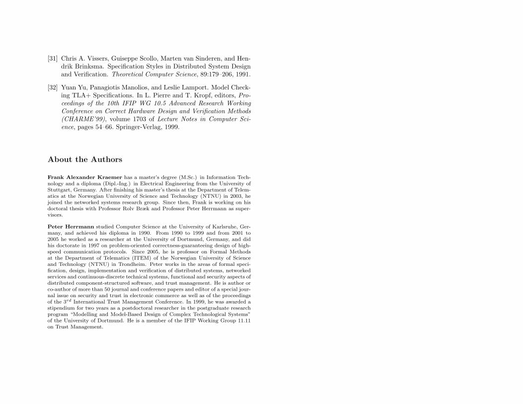
[31] Chris A. Vissers, Guiseppe Scollo, Marten van Sinderen, and Hen-drik Brinksma. Specification Styles in Distributed System Designand Verification. Theoretical Computer Science, 89:179–206, 1991.
[32] Yuan Yu, Panagiotis Manolios, and Leslie Lamport. Model Check-ing TLA+ Specifications. In L. Pierre and T. Kropf, editors, Pro-ceedings of the 10th IFIP WG 10.5 Advanced Research WorkingConference on Correct Hardware Design and Verification Methods(CHARME’99), volume 1703 of Lecture Notes in Computer Sci-ence, pages 54–66. Springer-Verlag, 1999.
About the Authors
Frank Alexander Kraemer has a master’s degree (M.Sc.) in Information Tech-nology and a diploma (Dipl.-Ing.) in Electrical Engineering from the University ofStuttgart, Germany. After finishing his master’s thesis at the Department of Telem-atics at the Norwegian University of Science and Technology (NTNU) in 2003, hejoined the networked systems research group. Since then, Frank is working on hisdoctoral thesis with Professor Rolv Bræk and Professor Peter Herrmann as super-visors.
Peter Herrmann studied Computer Science at the University of Karlsruhe, Ger-many, and achieved his diploma in 1990. From 1990 to 1999 and from 2001 to2005 he worked as a researcher at the University of Dortmund, Germany, and didhis doctorate in 1997 on problem-oriented correctness-guaranteeing design of high-speed communication protocols. Since 2005, he is professor on Formal Methodsat the Department of Telematics (ITEM) of the Norwegian University of Scienceand Technology (NTNU) in Trondheim. Peter works in the areas of formal speci-fication, design, implementation and verification of distributed systems, networkedservices and continuous-discrete technical systems, functional and security aspects ofdistributed component-structured software, and trust management. He is author orco-author of more than 50 journal and conference papers and editor of a special jour-nal issue on security and trust in electronic commerce as well as of the proceedingsof the 3rd International Trust Management Conference. In 1999, he was awarded astipendium for two years as a postdoctoral researcher in the postgraduate researchprogram “Modelling and Model-Based Design of Complex Technological Systems”of the University of Dortmund. He is a member of the IFIP Working Group 11.11on Trust Management.