Request For Quotation - Orpic - Oman Oil Refineries and Petroleum … · 2017-03-06 · Having...
117
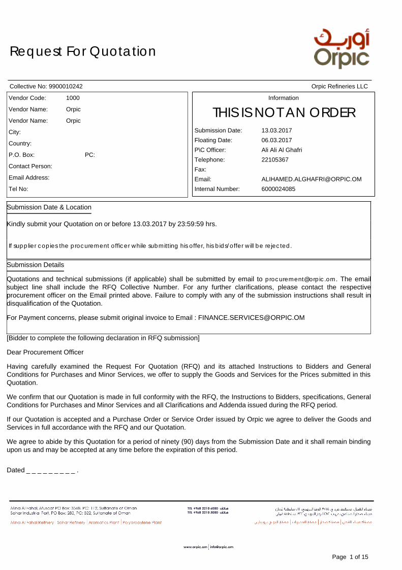
Request For Quotation Collective No: 9900010242 Orpic Refineries LLC Vendor Code: 1000 Vendor Name: Orpic Vendor Name: Orpic City: Country: P.O. Box: PC: Contact Person: Email Address: Tel No: Information THIS IS NOT AN ORDER Submission Date: 13.03.2017 Floating Date: 06.03.2017 P\C Officer: Ali Ali Al Ghafri Telephone: 22105367 Fax: Email: [email protected] Internal Number: 6000024085 Submission Date & Location Kindly submit your Quotation on or before 13.03.2017 by 23:59:59 hrs. If supplier copies the procurement officer while submitting his offer, his bids/offer will be rejected. Submission Details Quotations and technical submissions (if applicable) shall be submitted by email to [email protected]. The email subject line shall include the RFQ Collective Number. For any further clarifications, please contact the respective procurement officer on the Email printed above. Failure to comply with any of the submission instructions shall result in disqualification of the Quotation. For Payment concerns, please submit original invoice to Email : [email protected] [Bidder to complete the following declaration in RFQ submission] Dear Procurement Officer Having carefully examined the Request For Quotation (RFQ) and its attached Instructions to Bidders and General Conditions for Purchases and Minor Services, we offer to supply the Goods and Services for the Prices submitted in this Quotation. We confirm that our Quotation is made in full conformity with the RFQ, the Instructions to Bidders, specifications, General Conditions for Purchases and Minor Services and all Clarifications and Addenda issued during the RFQ period. If our Quotation is accepted and a Purchase Order or Service Order issued by Orpic we agree to deliver the Goods and Services in full accordance with the RFQ and our Quotation. We agree to abide by this Quotation for a period of ninety (90) days from the Submission Date and it shall remain binding upon us and may be accepted at any time before the expiration of this period. Dated _ _ _ _ _ _ _ _ _ . Page 1 of 15
Transcript of Request For Quotation - Orpic - Oman Oil Refineries and Petroleum … · 2017-03-06 · Having...
Request For Quotation
Collective No: 9900010242 Orpic Refineries LLC
Vendor Code: 1000
Vendor Name: Orpic
Vendor Name: Orpic
City:
Country:
P.O. Box: PC:
Contact Person:
Email Address:
Tel No:
Information
THIS IS NOT AN ORDERSubmission Date: 13.03.2017Floating Date: 06.03.2017P\C Officer: Ali Ali Al GhafriTelephone: 22105367Fax:Email: [email protected] Number: 6000024085
Submission Date & Location
Kindly submit your Quotation on or before 13.03.2017 by 23:59:59 hrs.
If supplier copies the procurement officer while submitting his offer, his bids/offer will be rejected.
Submission Details
Quotations and technical submissions (if applicable) shall be submitted by email to [email protected]. The emailsubject line shall include the RFQ Collective Number. For any further clarifications, please contact the respectiveprocurement officer on the Email printed above. Failure to comply with any of the submission instructions shall result indisqualification of the Quotation.
For Payment concerns, please submit original invoice to Email : [email protected]
[Bidder to complete the following declaration in RFQ submission]
Dear Procurement Officer
Having carefully examined the Request For Quotation (RFQ) and its attached Instructions to Bidders and GeneralConditions for Purchases and Minor Services, we offer to supply the Goods and Services for the Prices submitted in thisQuotation.
We confirm that our Quotation is made in full conformity with the RFQ, the Instructions to Bidders, specifications, GeneralConditions for Purchases and Minor Services and all Clarifications and Addenda issued during the RFQ period.
If our Quotation is accepted and a Purchase Order or Service Order issued by Orpic we agree to deliver the Goods andServices in full accordance with the RFQ and our Quotation.
We agree to abide by this Quotation for a period of ninety (90) days from the Submission Date and it shall remain bindingupon us and may be accepted at any time before the expiration of this period.
Dated _ _ _ _ _ _ _ _ _ .
Page 1 of 15
Request For Quotation
Collective No: 9900010242 Orpic Refineries LLC
Signed _ _ _ _ _ _ _ _ _ _ _ _ _.
Name: _ _ _ _ _ _ _ _ _ _ _ _ _ _ _ _ _ _ _ _ .
Title: _ _ _ _ _ _ _ _ _ _ _ _
for and on behalf of_ _ _ _ _ _ _ _ _ _ _ _ _ _ _ _ _
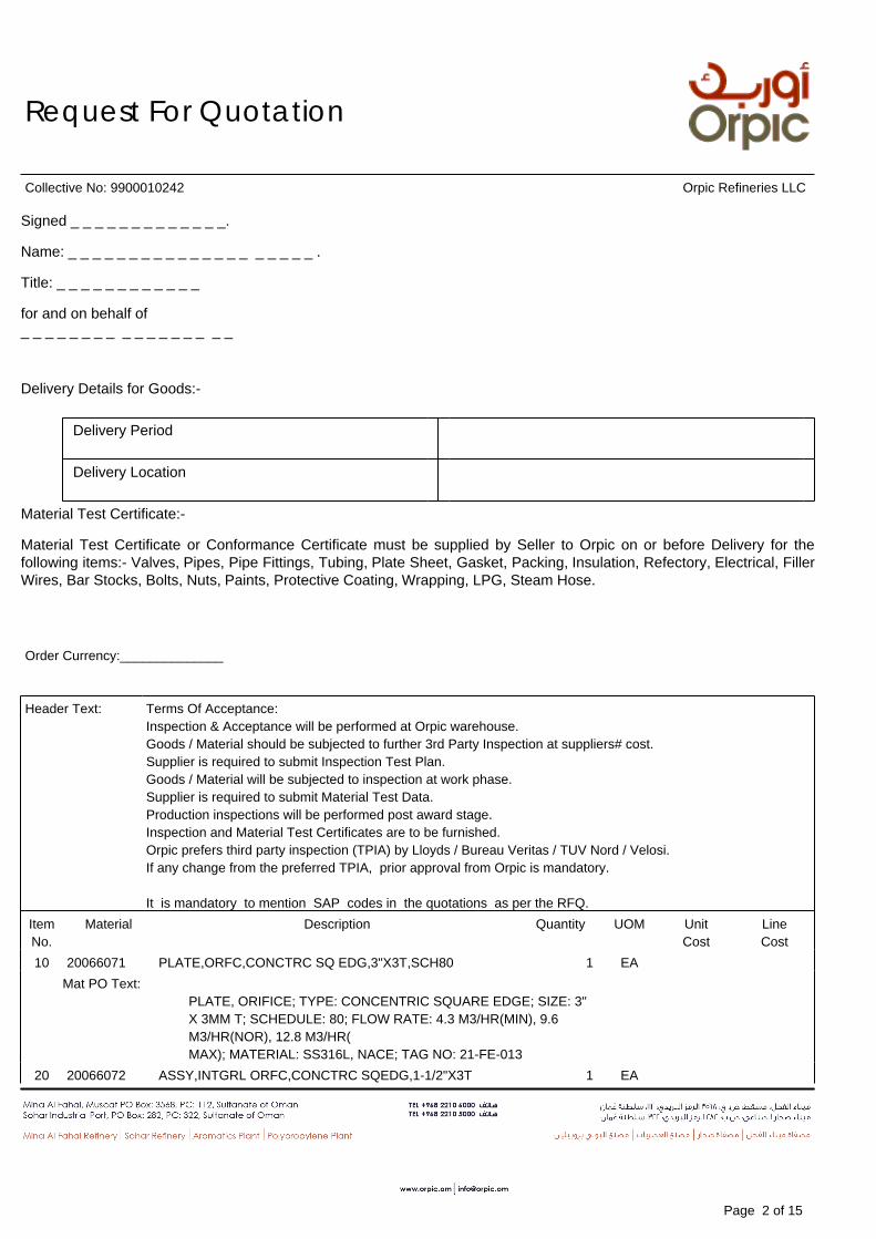
Delivery Details for Goods:-
Delivery Period
Delivery Location
Material Test Certificate:-
Material Test Certificate or Conformance Certificate must be supplied by Seller to Orpic on or before Delivery for thefollowing items:- Valves, Pipes, Pipe Fittings, Tubing, Plate Sheet, Gasket, Packing, Insulation, Refectory, Electrical, FillerWires, Bar Stocks, Bolts, Nuts, Paints, Protective Coating, Wrapping, LPG, Steam Hose.
Order Currency:______________
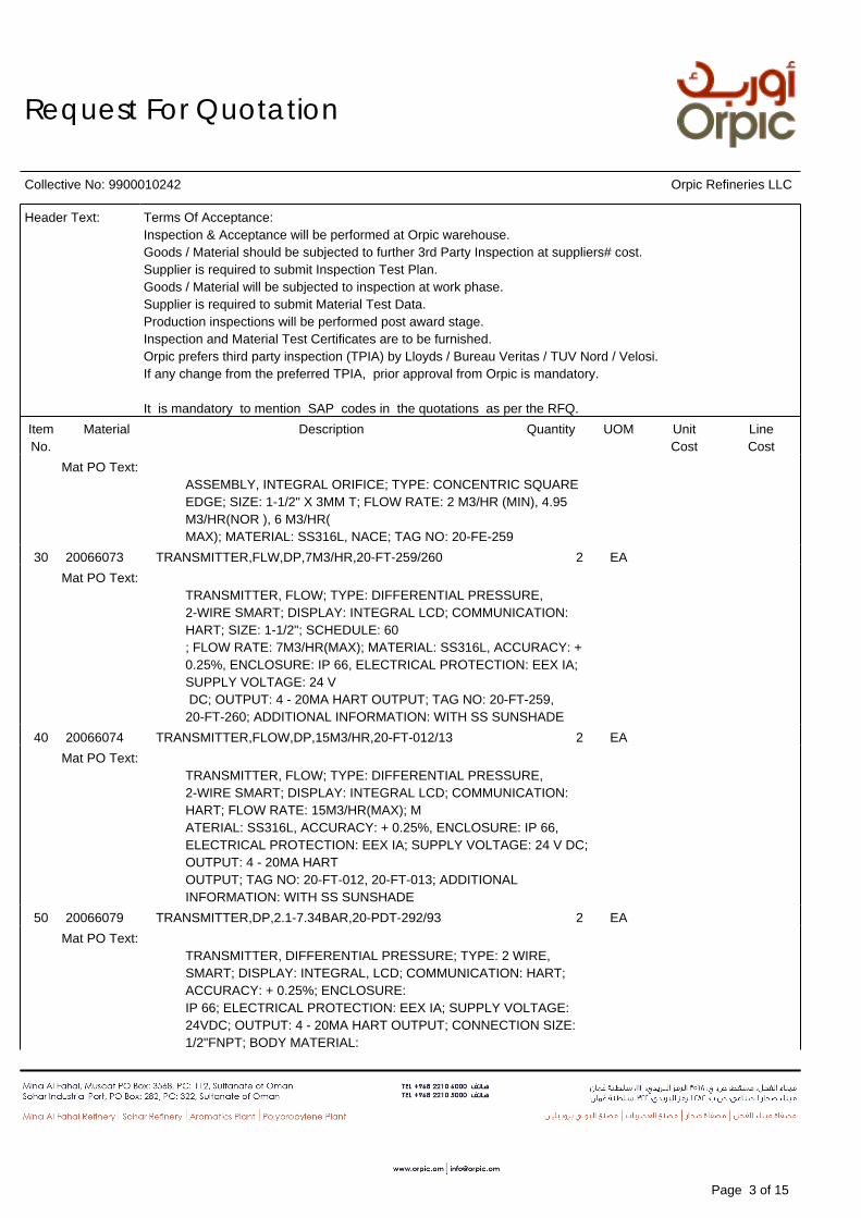
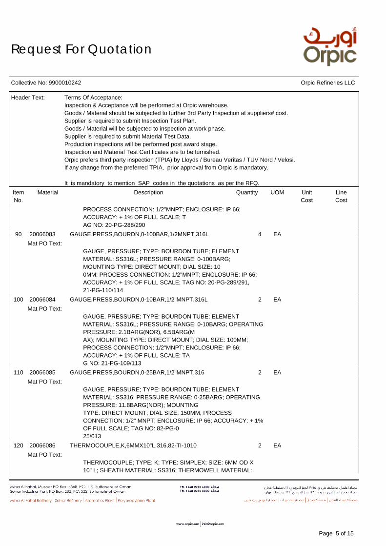
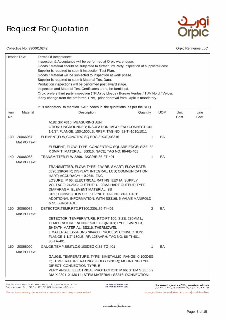
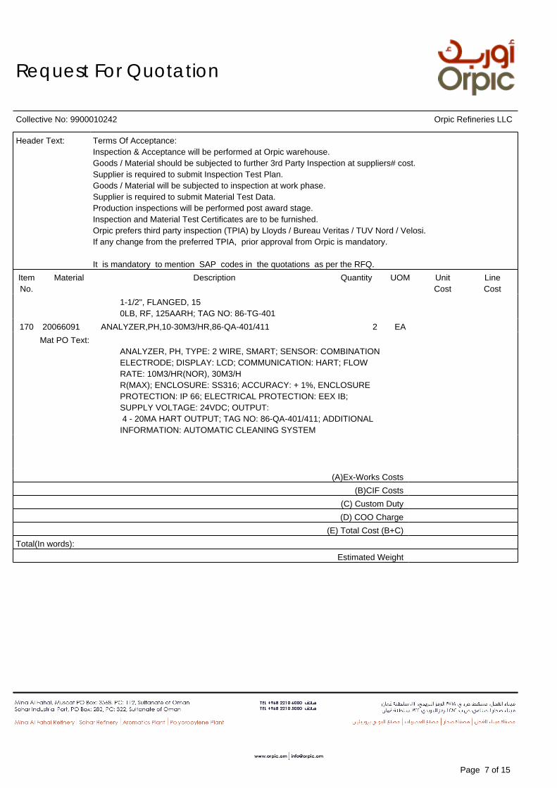
Header Text: Terms Of Acceptance:Inspection & Acceptance will be performed at Orpic warehouse.Goods / Material should be subjected to further 3rd Party Inspection at suppliers# cost.Supplier is required to submit Inspection Test Plan.Goods / Material will be subjected to inspection at work phase.Supplier is required to submit Material Test Data.Production inspections will be performed post award stage.Inspection and Material Test Certificates are to be furnished.Orpic prefers third party inspection (TPIA) by Lloyds / Bureau Veritas / TUV Nord / Velosi.If any change from the preferred TPIA, prior approval from Orpic is mandatory.
It is mandatory to mention SAP codes in the quotations as per the RFQ.ItemNo.
Material Description Quantity UOM UnitCost
LineCost
10 20066071 PLATE,ORFC,CONCTRC SQ EDG,3"X3T,SCH80 1 EAMat PO Text:
PLATE, ORIFICE; TYPE: CONCENTRIC SQUARE EDGE; SIZE: 3"X 3MM T; SCHEDULE: 80; FLOW RATE: 4.3 M3/HR(MIN), 9.6M3/HR(NOR), 12.8 M3/HR(MAX); MATERIAL: SS316L, NACE; TAG NO: 21-FE-013
20 20066072 ASSY,INTGRL ORFC,CONCTRC SQEDG,1-1/2"X3T 1 EA
Page 2 of 15
Request For Quotation
Collective No: 9900010242 Orpic Refineries LLC
Header Text: Terms Of Acceptance:Inspection & Acceptance will be performed at Orpic warehouse.Goods / Material should be subjected to further 3rd Party Inspection at suppliers# cost.Supplier is required to submit Inspection Test Plan.Goods / Material will be subjected to inspection at work phase.Supplier is required to submit Material Test Data.Production inspections will be performed post award stage.Inspection and Material Test Certificates are to be furnished.Orpic prefers third party inspection (TPIA) by Lloyds / Bureau Veritas / TUV Nord / Velosi.If any change from the preferred TPIA, prior approval from Orpic is mandatory.
It is mandatory to mention SAP codes in the quotations as per the RFQ.ItemNo.
Material Description Quantity UOM UnitCost
LineCost
Mat PO Text:ASSEMBLY, INTEGRAL ORIFICE; TYPE: CONCENTRIC SQUAREEDGE; SIZE: 1-1/2" X 3MM T; FLOW RATE: 2 M3/HR (MIN), 4.95M3/HR(NOR ), 6 M3/HR(MAX); MATERIAL: SS316L, NACE; TAG NO: 20-FE-259
30 20066073 TRANSMITTER,FLW,DP,7M3/HR,20-FT-259/260 2 EAMat PO Text:
TRANSMITTER, FLOW; TYPE: DIFFERENTIAL PRESSURE,2-WIRE SMART; DISPLAY: INTEGRAL LCD; COMMUNICATION:HART; SIZE: 1-1/2"; SCHEDULE: 60; FLOW RATE: 7M3/HR(MAX); MATERIAL: SS316L, ACCURACY: +0.25%, ENCLOSURE: IP 66, ELECTRICAL PROTECTION: EEX IA;SUPPLY VOLTAGE: 24 V DC; OUTPUT: 4 - 20MA HART OUTPUT; TAG NO: 20-FT-259,20-FT-260; ADDITIONAL INFORMATION: WITH SS SUNSHADE
40 20066074 TRANSMITTER,FLOW,DP,15M3/HR,20-FT-012/13 2 EAMat PO Text:
TRANSMITTER, FLOW; TYPE: DIFFERENTIAL PRESSURE,2-WIRE SMART; DISPLAY: INTEGRAL LCD; COMMUNICATION:HART; FLOW RATE: 15M3/HR(MAX); MATERIAL: SS316L, ACCURACY: + 0.25%, ENCLOSURE: IP 66,ELECTRICAL PROTECTION: EEX IA; SUPPLY VOLTAGE: 24 V DC;OUTPUT: 4 - 20MA HARTOUTPUT; TAG NO: 20-FT-012, 20-FT-013; ADDITIONALINFORMATION: WITH SS SUNSHADE
50 20066079 TRANSMITTER,DP,2.1-7.34BAR,20-PDT-292/93 2 EAMat PO Text:
TRANSMITTER, DIFFERENTIAL PRESSURE; TYPE: 2 WIRE,SMART; DISPLAY: INTEGRAL, LCD; COMMUNICATION: HART;ACCURACY: + 0.25%; ENCLOSURE:IP 66; ELECTRICAL PROTECTION: EEX IA; SUPPLY VOLTAGE:24VDC; OUTPUT: 4 - 20MA HART OUTPUT; CONNECTION SIZE:1/2"FNPT; BODY MATERIAL:
Page 3 of 15

Request For Quotation
Collective No: 9900010242 Orpic Refineries LLC
Header Text: Terms Of Acceptance:Inspection & Acceptance will be performed at Orpic warehouse.Goods / Material should be subjected to further 3rd Party Inspection at suppliers# cost.Supplier is required to submit Inspection Test Plan.Goods / Material will be subjected to inspection at work phase.Supplier is required to submit Material Test Data.Production inspections will be performed post award stage.Inspection and Material Test Certificates are to be furnished.Orpic prefers third party inspection (TPIA) by Lloyds / Bureau Veritas / TUV Nord / Velosi.If any change from the preferred TPIA, prior approval from Orpic is mandatory.
It is mandatory to mention SAP codes in the quotations as per the RFQ.ItemNo.
Material Description Quantity UOM UnitCost
LineCost
SS316L; PRESSURE RATING: 2.1BARG (NOR), 7.34BARG (MAX);TAG NO: 20-PDT-292/293; ADDITIONAL INFORMATION: WITHSS316L 5 VALVE MANIFOLD & SS SUNSHADE
60 20066080 TRANSMITTER,DP,2.1-6.5BAR,21-PDT-108/112 2 EAMat PO Text:
TRANSMITTER, DIFFERENTIAL PRESSURE; TYPE: 2 WIRE,SMART; DISPLAY: INTEGRAL, LCD; COMMUNICATION: HART;ACCURACY: + 0.25%; ENCLOSURE:IP 66; ELECTRICAL PROTECTION: EEX IA; SUPPLY VOLTAGE:24VDC; OUTPUT: 4 - 20MA HART OUTPUT; CONNECTION SIZE:1/2"FNPT; BODY MATERIAL: SS316L; PRESSURE RATING: 2.1BARG (NOR), 6.5BARG (MAX);TAG NO: 21-PDT-108/112; ADDITIONAL INFORMATION: WITHSS316L 5 VALVE MANIFOLD & SS SUNSHADE
70 20066081 TRANSMITTER,PRESS,2.1-7.34BAR,20-PT-294 1 EAMat PO Text:
TRANSMITTER, PRESSURE; TYPE: 2 WIRE, SMART; DISPLAY:INTEGRAL, LCD; COMMUNICATION: HART; ACCURACY: + 0.25%;ENCLOSURE: IP 66; ELECTRICAL PROTECTION: EEX IA; SUPPLY VOLTAGE: 24VDC;OUTPUT: 4 - 20MA HART OUTPUT; CONNECTION SIZE:1/2"FNPT; BODY MATERIAL: SS316L; PRESSURE RATING: 2.1BARG (NOR), 7.34BARG (MAX); TAG NO:20-PT-294; ADDITIONAL INFORMATION: WITH SS316L 2 VALVEMANIFOLD & SS SUNSHADE
80 20066082 GAUGE,PRESS,BOURDN,0-16BAR,1/2"MNPT,316L 2 EAMat PO Text:
GAUGE, PRESSURE; TYPE: BOURDON TUBE; ELEMENTMATERIAL: SS316L; PRESSURE RANGE: 0-16BARG; OPERATINGPRESSURE: 2.1BARG(NOR), 7.34BARG(MAX); MOUNTING TYPE: DIRECT MOUNT; DIAL SIZE: 100MM;
Page 4 of 15
Request For Quotation
Collective No: 9900010242 Orpic Refineries LLC
Header Text: Terms Of Acceptance:Inspection & Acceptance will be performed at Orpic warehouse.Goods / Material should be subjected to further 3rd Party Inspection at suppliers# cost.Supplier is required to submit Inspection Test Plan.Goods / Material will be subjected to inspection at work phase.Supplier is required to submit Material Test Data.Production inspections will be performed post award stage.Inspection and Material Test Certificates are to be furnished.Orpic prefers third party inspection (TPIA) by Lloyds / Bureau Veritas / TUV Nord / Velosi.If any change from the preferred TPIA, prior approval from Orpic is mandatory.
It is mandatory to mention SAP codes in the quotations as per the RFQ.ItemNo.
Material Description Quantity UOM UnitCost
LineCost
PROCESS CONNECTION: 1/2"MNPT; ENCLOSURE: IP 66;ACCURACY: + 1% OF FULL SCALE; TAG NO: 20-PG-288/290
90 20066083 GAUGE,PRESS,BOURDN,0-100BAR,1/2MNPT,316L 4 EAMat PO Text:
GAUGE, PRESSURE; TYPE: BOURDON TUBE; ELEMENTMATERIAL: SS316L; PRESSURE RANGE: 0-100BARG;MOUNTING TYPE: DIRECT MOUNT; DIAL SIZE: 100MM; PROCESS CONNECTION: 1/2"MNPT; ENCLOSURE: IP 66;ACCURACY: + 1% OF FULL SCALE; TAG NO: 20-PG-289/291,21-PG-110/114
100 20066084 GAUGE,PRESS,BOURDN,0-10BAR,1/2"MNPT,316L 2 EAMat PO Text:
GAUGE, PRESSURE; TYPE: BOURDON TUBE; ELEMENTMATERIAL: SS316L; PRESSURE RANGE: 0-10BARG; OPERATINGPRESSURE: 2.1BARG(NOR), 6.5BARG(MAX); MOUNTING TYPE: DIRECT MOUNT; DIAL SIZE: 100MM;PROCESS CONNECTION: 1/2"MNPT; ENCLOSURE: IP 66;ACCURACY: + 1% OF FULL SCALE; TAG NO: 21-PG-109/113
110 20066085 GAUGE,PRESS,BOURDN,0-25BAR,1/2"MNPT,316 2 EAMat PO Text:
GAUGE, PRESSURE; TYPE: BOURDON TUBE; ELEMENTMATERIAL: SS316; PRESSURE RANGE: 0-25BARG; OPERATINGPRESSURE: 11.8BARG(NOR); MOUNTINGTYPE: DIRECT MOUNT; DIAL SIZE: 150MM; PROCESSCONNECTION: 1/2" MNPT; ENCLOSURE: IP 66; ACCURACY: + 1%OF FULL SCALE; TAG NO: 82-PG-025/013
120 20066086 THERMOCOUPLE,K,6MMX10"L,316,82-TI-1010 2 EAMat PO Text:
THERMOCOUPLE; TYPE: K; TYPE: SIMPLEX; SIZE: 6MM OD X10" L; SHEATH MATERIAL: SS316; THERMOWELL MATERIAL:
Page 5 of 15
Request For Quotation
Collective No: 9900010242 Orpic Refineries LLC
Header Text: Terms Of Acceptance:Inspection & Acceptance will be performed at Orpic warehouse.Goods / Material should be subjected to further 3rd Party Inspection at suppliers# cost.Supplier is required to submit Inspection Test Plan.Goods / Material will be subjected to inspection at work phase.Supplier is required to submit Material Test Data.Production inspections will be performed post award stage.Inspection and Material Test Certificates are to be furnished.Orpic prefers third party inspection (TPIA) by Lloyds / Bureau Veritas / TUV Nord / Velosi.If any change from the preferred TPIA, prior approval from Orpic is mandatory.
It is mandatory to mention SAP codes in the quotations as per the RFQ.ItemNo.
Material Description Quantity UOM UnitCost
LineCost
A182 GR F316; MEASURING JUNCTION: UNGROUNDED; INSULATION: MGO; END CONNECTION:1-1/2", FLANGE, 150-1500LB, RFSF; TAG NO: 82-TI-1010/1011
130 20066087 ELEMENT,FLW,CONCTRC SQ EDG,3"X3T,SS316 1 EAMat PO Text:
ELEMENT, FLOW; TYPE: CONCENTRIC SQUARE EDGE; SIZE: 3"X 3MM T; MATERIAL: SS316, NACE; TAG NO: 86-FE-401
140 20066088 TRANSMITTER,FLW,3396.13KG/HR,86-FT-401 1 EAMat PO Text:
TRANSMITTER, FLOW; TYPE: 2 WIRE, SMART; FLOW RATE:3396.13KG/HR; DISPLAY: INTEGRAL, LCD; COMMUNICATION:HART; ACCURACY: + 0.25%; ENCLOSURE: IP 66; ELECTRICAL RATING: EEX IA; SUPPLYVOLTAGE: 24VDC; OUTPUT: 4 - 20MA HART OUTPUT; TYPE:DIAPHRAGM; ELEMENT MATERIAL: SS316L; CONNECTION SIZE: 1/2"NPT; TAG NO: 86-FT-401;ADDITIONAL INFORMATION: WITH SS316L 5 VALVE MANIFOLD& SS SUNSHADE
150 20066089 DETECTOR,TEMP,RTD,PT100,230L,86-TI-401 2 EAMat PO Text:
DETECTOR, TEMPERATURE; RTD-PT 100; SIZE: 230MM L;TEMPERATURE RATING: 93DEG C(NOR); TYPE: SIMPLEX,SHEATH MATERIAL: SS316, THERMOWELL MATERIAL: B564 UNS N04400; PROCESS CONNECTION:FLANGE-1-1/2"-150LB, RF, 125AARH; TAG NO: 86-TI-401,86-TA-401
160 20066090 GAUGE,TEMP,BIMTLC,0-100DEG C,86-TG-401 1 EAMat PO Text:
GAUGE, TEMPERATURE; TYPE; BIMETALLIC; RANGE: 0-100DEGC; TEMPERATURE RATING: 93DEG C(NOR); MOUNTING TYPE:DIRECT, CONNECTION TYPE: EVERY ANGLE; ELECTRICAL PROTECTION: IP 66; STEM SIZE: 6.2DIA X 230 L X 430 L1; STEM MATERIAL: SS316; DONNECTION:
Page 6 of 15
Request For Quotation
Collective No: 9900010242 Orpic Refineries LLC
Header Text: Terms Of Acceptance:Inspection & Acceptance will be performed at Orpic warehouse.Goods / Material should be subjected to further 3rd Party Inspection at suppliers# cost.Supplier is required to submit Inspection Test Plan.Goods / Material will be subjected to inspection at work phase.Supplier is required to submit Material Test Data.Production inspections will be performed post award stage.Inspection and Material Test Certificates are to be furnished.Orpic prefers third party inspection (TPIA) by Lloyds / Bureau Veritas / TUV Nord / Velosi.If any change from the preferred TPIA, prior approval from Orpic is mandatory.
It is mandatory to mention SAP codes in the quotations as per the RFQ.ItemNo.
Material Description Quantity UOM UnitCost
LineCost
1-1/2", FLANGED, 150LB, RF, 125AARH; TAG NO: 86-TG-401
170 20066091 ANALYZER,PH,10-30M3/HR,86-QA-401/411 2 EAMat PO Text:
ANALYZER, PH, TYPE: 2 WIRE, SMART; SENSOR: COMBINATIONELECTRODE; DISPLAY: LCD; COMMUNICATION: HART; FLOWRATE: 10M3/HR(NOR), 30M3/HR(MAX); ENCLOSURE: SS316; ACCURACY: + 1%, ENCLOSUREPROTECTION: IP 66; ELECTRICAL PROTECTION: EEX IB;SUPPLY VOLTAGE: 24VDC; OUTPUT: 4 - 20MA HART OUTPUT; TAG NO: 86-QA-401/411; ADDITIONALINFORMATION: AUTOMATIC CLEANING SYSTEM
(A)Ex-Works Costs(B)CIF Costs
(C) Custom Duty(D) COO Charge
(E) Total Cost (B+C)Total(In words):
Estimated Weight
Page 7 of 15
Request For Quotation
Collective No: 9900010242 Orpic Refineries LLC
1 Orpic Definitions and RFQ/PO Instructions to Bidders for RFQ, PO & PC
1.1 Orpic is the brand name of Oman Oil Refineries and Petroleum Industries Company SAOC (Commercial Registration Number 1113003). OrpicAromatics is the brand name of Aromatics Oman LLC (Commercial Registration Number 1798189). Orpic Refineries is the brand name of OrpicRefineries LLC (Commercial Registration Number 1134221). Orpic Plastics is the brand name of Orpic Plastics LLC (Commercial Registration Number1218747). The Orpic brand represents the integrated management of these operating companies and this RFQ may be issued by Orpic for and onbehalf of any or all of these operating companies, together with Orpic#s and their respective co-ventures, affiliates, officers, employees and agents,collectively the #Orpic Group".
1.2 Bidder is Company responding to this RFQ with a Quotation. Bidder is requested to acknowledge receipt of this RFQ by return email to theProcurement Officer who issued the RFQ.
1.3 Seller/Contractor. For the purposes of this document Seller and Contractor shall mean the party that is contracted to Orpic.
1.4 Purchase Order, Service Order, Contract and Agreement shall mean the same.
1.5 Scope of Supply and/or Services shall be attached separately (if applicable)
1.6 Party means either of Orpic or the Seller/Contractor and Parties means both of them together.
1.7 Price means the price as more particularly described in the Service Order to be paid by Orpic to the Contractor.
1.8 Registration Requirements.Unless otherwise agreed by Orpic Bidder must be registered with Orpic & Joint Supplier Registration System (JSRS) as an approved Seller for thematerials / services to be offered by their Quotation. If Bidder is not registered, the registration forms are available from Orpic Procurement &Contracting Dept, PP Building, Sohar. Bidders may contact the Procurement Officer who issued the RFQ to arrange to collect the forms. These formsmust be completed and submitted by Bidder not less than 10 days before the Submission Date of this RFQ. Bidders must sign Orpic's ConfidentialityDeclaration or Non-Disclosure Agreement, (NDA) as directed by the Procurement Officer and submit with the Seller registration forms or the Quotation.
1.9 Quotation. Bidder shall submit its Quotation by completing the necessary sections of the enclosed Orpic RFQ only. Bidder may only indicatedeviations relating to the subject matter of the RFQ by clearly indicating where the Quotation differs from the RFQ requirements and any proposedamendments. However Orpic is not obliged to accept any deviations. Bidder shall provide the complete breakdown of pricing required. The Quotationand any resultant Purchase Order/Service Order shall be governed by Orpic General Conditions for Purchase and Minor Services, attached below, andOrpic may not accept any changes to these General Conditions of the Purchase Order for Purchase and Minor Services. Bidder must submit two signedcopies of the Purchase Order with all sections duly completed. Submitting a Quotation in any other format may result in Bidder's Quotation beingrejected at Orpic's sole discretion.
1.10 Acceptance. Acceptance by Orpic will be confirmed by the issuance of a Purchase Order/Service Order within the Quotation validity period whichshall be binding. One countersigned copy of the Purchase Order/Service Order may be returned to the Bidder.
1.11 Clarifications. If Bidder requires any further information or clarification regarding this RFQ then a request for clarification shall be sent in writing tothe Procurement Officer who issued the RFQ and whose name and email is stated above.
1.12 Regrets. If Bidder is not in a position to submit a Quotation, Bidder is requested to confirm by email to the Procurement mail.
1.13 Advance Payment Bond. If Orpic agrees to an Advance Payment then it will be on condition that the successful Bidder submits an AdvancePayment Bond in accordance with the General Conditions Applicable for Procurement of Goods and Services and in the exact format detailed inAppendix 3. If an Advance Payment for supply of Goods or Services is agreed then an Advance Payment Bond and or Bank Guarantee from aregistered bank in the Sultanate of Oman, acceptable to Orpic, in an amount equal to the Advance Payment shall be submitted by the Seller/Contractorto Orpic. Submission of any Advance Payment Bond or Bank Guarantee from a registered bank outside of the Sultanate of Oman shall be pre-approvedby Orpic prior to submission.
1.14 Submission of Quotation. The date, method and location for submitting the Quotation will be indicated on the front page of the RFQ. Any Quotationreceived after this date & time will be rejected or accepted at Orpic#s sole discretion.
1.15 No Obligation. Orpic is not obliged to accept the lowest priced Quotation or any Quotation. Orpic is not obliged to provide any reasons for rejectingany Quotation. Orpic may, at its sole discretion, reduce or increase the quantity ordered or split orders between Bidders.
1.16 Extension. Bidder must request any extension of time not less than 48 hours before the Submission Date. Orpic may or may not agree to award anextension at its sole discretion.
1.17 Validity. Bidder's Quotation shall be valid for not less than ninety (90) days from the Submission Date.
1.18 Tax means any and all net income, gross income, gross receipts, sales, use ad volorem, transfer, franchise, net worth, profits, license, lease,service, service use, withholding, payroll, employment, excise, severance, stamp, occupation, premium, property, real property taxes and fees, customs,duties or other taxes, fees, assesments levies, charges or other impositions of any kind whatsover or obligatory charge of like or equivalent nature,together with any interest thereof and any and all penalties, additions to tax, or additional amounts with respect thereto, imposed by or on behalf of anyGovernmental Authority.
Page 8 of 15

Request For Quotation
Collective No: 9900010242 Orpic Refineries LLC
2. General Conditions Applicable for Procurement of Goods and Services
2.1 Payment. The Price of the Goods and/or Services shall be the amount set out in the Purchase/Service Order. The Price is the total amount due tobe paid by Orpic to the Seller in respect of satisfactory performance by the Seller/Contractor of its obligations under this Purchase/Service Order. ThePrice is inclusive of amounts in respect of any applicable taxes duties or similar charges and for Goods includes the costs of packaging, insurance andcarriage of the Goods. No extra charges shall be effective unless agreed in writing and signed by Orpic. All costs associated with preparation ofSeller's/Contractor#s bid, quotation, development of offer or related to this Purchase/Service Order are for Seller's/Contactor#s account. Any legalizationcosts for packaging and documentation including Material Test Certificates or Conformance Certificates are for Seller's account. The Seller may invoiceOrpic for the Goods on or at any time after the completion of delivery. The Contractor may invoice Orpic for the Services performed on or at any timeafter Completion or as set out in the Scope of Services. Seller shall submit following documents for payment: Invoice; PO / PC copy; and Proof ofdelivery / service completion report.
2.2 Orpic shall pay undisputed and correctly rendered invoices from the Seller/Contractor within thirty (30) days of the later of either receipt of theinvoice or Completion of the Services or to acceptance of the Goods, as the case may be. Payment shall be made to the Contractor's bank account. Inthe event of a dispute over all part of an invoice, Orpic shall pay the undisputed part in accordance with this Clause and the Parties shall discuss in goodfaith to resolve the disputed part. Orpic may, without limiting any other rights or remedies it may have, set off any amount owed to it by theSeller/Contractor against any amounts payable by it to the Seller/Contractor under this Purchase/Service Order.
2.3 Audit Rights. Orpic shall have the right, to inspect and audit any of Seller's/Contractor#s records, including data stored on computers, books,personnel records, accounts, correspondence, memoranda, receipts, vouchers and other papers of every kind in connection with this Purchase/ServiceOrder and/or Goods and all transactions related thereto as may be necessary in the opinion of Orpic to verify that the requirements of thisPurchase/Service Order are being met and shall have access to all information relating to the rates and prices as may reasonably be required to verifypayments made to or by Seller/Contractor under or pursuant to this Purchase/Service Order. Such inspections and audits may be carried out by Orpic inrespect of this Purchase/Service Order at any time until expiry of twenty four (24) months from the end of the calendar year in which thisPurchase/Service Order is terminated or completed. Orpic shall use all reasonable endeavours to conduct any such inspections and audits in a mannerwhich shall result in a minimum of inconvenience to Seller/Contractor.
2.4 Liability & Indemnity. The Seller/Contractor shall indemnify Orpic against all liabilities, costs, expenses, damages and losses (including but notlimited to any direct losses and all interest, penalties and legal and other professional costs and expenses) suffered or incurred by Orpic arising out of orin connection with: a) any claim made against Orpic for actual or alleged infringement of a third party's IP Rights arising out of, or in connection with, thesupply or use of the Goods; b) any claim made against Orpic by a third party arising out of, or in connection with, the supply of the Goods, to the extentthat such claim arises out of the breach, negligent performance or failure or delay in performance of this Purchase/Service Order by theSeller/Contractor, its employees, agents or subcontractors; and c) any claim made against Orpic by a third party for death, personal injury or damage toproperty arising out of, or in connection with, defective Goods, to the extent that the defect in the Goods is attributable to the acts or omissions of theSeller/Contractor or Manufacturer, its employees, agents or subcontractors.
The Seller/Contractor shall indemnify Orpic from and against all claims ,liabilities or losses arising by reason of the following if connected with theperformance of this Purchase/Service Order: a) all injury to ,death, or illness of persons in the Supplier Group; and b) all damage to or loss of property ofthe Supplier Group, even if caused by negligence or fault of the Orpic Group or any other person. The Seller/Contractor shall indemnify Orpic from andagainst all claims, liabilities or losses arising by reason of the following if connected with the performance of this Contract: a) all injury to, death, orillness of third parties; and b) all damage to or loss of third parties' property, to the extent caused by the negligence or fault of the Supplier Group, even ifcontributed to by the joint or concurrent negligence or fault of the Orpic Group or any other person; provided that, in the event of joint or concurrentnegligence or fault of the Supplier Group and the Orpic Group, the Supplier's indemnification obligation shall be limited to the Supplier Group'sproportionate share of such negligence or fault.
Orpic shall indemnify the Seller/Contractor from and against all claims, liabilities or losses arising by reason of the following if connected with theperformance of this Purchase/Service Order: a) loss of or damage to Orpic's property, except that nothing in this clause will in any way limitSeller/Contractor's obligations to remedy defects, whether owned, leased or otherwise obtained under arrangements with financial institutions arisingfrom or related to the performance of this Purchase/Service Order; b) Personal injury including death or disease to any person who is an employee ofOrpic arising from or relating to the performance of this Purchase/Service Order; c) subject to any other express provisions of this Purchase/ServiceOrder, personal injury including death or disease or loss of or damage to the property of any third party to the extent that any such injury, loss or damageis caused by Orpic's negligence or breach of duty (whether statutory or otherwise).
2.5 Consequential Loss shall mean: Consequential loss; and/or loss of production, loss of product, loss of use, loss of business and businessinterruption and loss of revenue, profit or anticipated profit whether direct or indirect arising from or related to the performance of this Purchase/ServiceOrder, whether or not such losses were foreseeable at the time of entering into this Purchase/Service Order. Except to the extent of any agreedremedies expressly provided for in this Agreement but notwithstanding anything else to the contrary in this Agreement, neither Orpic nor Contractor shallbe liable to the other for any Consequential Loss which may be suffered by the other in connection with this Agreement.
2.6 Applicable Law and Dispute Resolution. The laws of the Sultanate of Oman shall govern the construction, validity and performance of thisPurchase/Service Order. Unless otherwise agreed, any dispute arising out of or in connection with this Purchase/Service Order which cannot beresolved to the mutual satisfaction of the Parties then the Parties hereto agree to submit to the jurisdiction of the courts of Oman to resolve any matter indispute.
2.7 Force Majeure. Except as may be specifically otherwise provided in this Purchase/Service Order, neither Party shall be liable for delays inperformance or for non-performance directly occasioned or caused by Force Majeure. Force Majeure means Acts of God, war (declared andundeclared), riots, civil commotion, revolution, hostilities, epidemics, blockades, nuclear hazards, extreme weather conditions, acts of any Governmentcausing a political embargo or other political restraint adversely affecting the freedom to transact business with or in the Sultanate of Oman and anyother similar cause or of equivalent force occurring within the Sultanate of Oman which is beyond the control of the Parties, unavoidable and whichcould not reasonably be foreseen and which renders impossible the fulfilment of a particular term of this Purchase/Service Order. Strikes, lockouts or
Page 9 of 15
Request For Quotation
Collective No: 9900010242 Orpic Refineries LLC
differences with workers which are limited to Seller/Contractor's personnel or those of Seller/Contractor's sub-Seller/Contractors and inability of eitherParty to secure funds shall not be regarded as Force Majeure.
2.8 Assignment and Sub-Contracting. Seller/Contractor may not assign, subcontract or transfer any part of this Purchase/Service Order or theobligations of Seller/Contractor under or related to this Purchase/Service Order without the prior written approval of Orpic. Approval by Orpic of asub-contractor shall not relieve Seller/Contractor from its responsibility for performance of the part of this Purchase/Service Order that is subcontracted.
2.9 Confidential Information. All information obtained by Seller/Contractor for or in connection with this Purchase/Service Order and Seller/Contractor'ssupply of the Goods/Services shall be considered confidential and shall not be used by Seller/Contractor other than for the purposes of supplying theGoods/Services, or divulged by Seller/Contractor, its servants or agents to any person, firm or corporation other than Orpic#s designated representative.The foregoing restrictions shall not apply to any information disclosed by Orpic to Seller/Contractor which: a) At the time of disclosure is in the publicdomain, or b) After disclosure becomes part of the public domain, or c) Seller/Contractor can show was rightfully in its possession at the time ofdisclosure without limitation or restriction as to use or disclosure, and was not acquired directly or indirectly from Orpic, or d) Seller/Contractor rightfullyreceives from any third party who did not receive such information directly or indirectly from Orpic with limitation or restriction as to use or disclosure.
2.10 Termination. In the event of Seller/Contractor's failure to perform or other breach of this Purchase/Service Order, Orpic shall have the right toterminate this Purchase/Service Order forthwith without being first obliged to seek any remedy by Seller/Contractor. Termination under this clause shallbe at no extra cost to Orpic. Orpic reserves the right to terminate this Purchase/Service Order at any time by giving Seller/Contractor written notificationspecifying the date of termination. Orpic shall pay Seller/Contractor for Goods satisfactorily delivered and accepted and Services satisfactorilyperformed and accepted up to the date of termination and other reasonable associated direct costs incurred in complying with Orpic's instructions. In noevent shall Seller/Contractor be entitled to any prospective profits or any damages resulting from such termination.
2.11 Costs. Each Party shall pay its own costs incurred in connection with the negotiation, preparation, execution and performance of this agreementand any documents referred to in it.
2.12 Variation. No variation of this agreement shall be effective unless it is in writing and signed by the Parties (or their authorised representatives).
2.13 Waiver. No failure or delay by a Party to exercise any right or remedy provided under this agreement or by law shall constitute a waiver of that orany other right or remedy, nor shall it prevent or restrict the further exercise of that or any other right or remedy. No single or partial exercise of suchright or remedy shall prevent or restrict the further exercise of that or any other right or remedy.
2.14 Language. This Purchase/Service Order is drafted in the English language. If this Purchase/Service Order is translated into any other language, theEnglish language version shall prevail.
2.15 Notices. A notice given to a Party under or in connection with this Purchase/Service Order shall be in writing and sent to the Party at the address orto the fax number given in this Purchase/Service Order or as otherwise notified in writing to the other Party. Any notice given under or in connectionwith this Purchase/Service Order shall be in the English language. All other documents provided under or in connection with this agreement shall be inthe English language, or accompanied by a certified English translation. If such document is translated into any other language, the English languageversion shall prevail unless the document is a constitutional, statutory or other official document.
2.16 Anti-Bribery and Corruption. A Person shall be defined as a third party including, but not limited to: government officials (including directors,officers and employees of government owned and/or controlled entities); any director, officer or employee of Orpic or its subsidiaries, or their relatives;any candidate for public office; or any agents or intermediaries of any of the foregoing. The Seller/Contractor agrees and confirms that, in connectionwith the award or execution of the Purchase/Service Order, and any and all transactions contemplated by this Purchase/Service Order, it will fullycomply with all applicable legislation relating to anti-bribery and anti-corruption, including, but not limited to, Royal Decrees (including: Royal Decree 7 of1974 promulgating the Oman Penal Code; Royal Decree 112 of 2011 promulgating the Law of the Protection of Public Funds and Avoidance ofConflicts; and Royal Decree 64 of 2013 ratifying the United Nations Convention Against Corruption), regulations, ministerial directions and orders of theSultanate of Oman. The Seller/Contractor agrees and confirms that it, and each of its affiliates, and their respective directors, officers, employees,agents and any other person acting on its, or their, behalf has not, and will not, directly or indirectly, make, offer, authorise, promise, mediate or becomeany way involved in a payment or transfer of anything in value, including the provision of any advantage or any showing or providing favour or disfavourto anybody, or any service, gift, entertainment, promise, reward, rebate, discount, contribution, commission, incentive, inducement, to any Person whichis intended to be, or could reasonably be construed or perceived as being, an inducement or reward for that Person doing or not doing any act, orpromising to do or not to do any act. The Seller/Contractor agrees and confirms that, in connection with the award or execution of the Purchase/ServiceOrder, and any and all transactions contemplated by this Purchase/Service Order, it has and will apply effective anti-bribery and corruption reporting anddisclosure controls and procedures and has and will maintain internal accounting systems that are sufficient to show, in reasonable detail, alltransactions undertaken in relation thereto. Without prejudice to any other rights that the Seller/Contractor may have under law or otherwise, should theSeller/Contractor be considered to be in breach of any of the above provisions, Orpic may, upon written notice, immediately disqualify theSeller/Contractor from bidding, quoting, tendering, applying for or otherwise entering into the proposed Purchase/Service Order or terminate thisPurchase/Service Order (as the case may be) and refuse to allow the Seller to bid, quote, tender, apply or enter into any further or futurePurchase/Service orders, contracts or agreements with Orpic. The Seller/Contractor shall defend, indemnify and hold Orpic harmless from and againstany and all claims, damages, losses, penalties, costs and expenses arising from or related to, any breach of its commitments in this clause. Thisindemnity obligation shall survive termination or expiration of this Purchase/Service Order.
2.17 Business Ethics. In connection with Seller/Contractors performance of this Purchase/Service Order, Seller/Contractor undertakes that it willundertake and agree to act consistently with and to adhere to the principles of Orpic's General Business Principle in connection with Seller/Contractor'sperformance of this Purchase/Service Order. Failure to comply with this provision may constitute a Material Default giving rise to termination.
2.18 IP / Software. Where, as part of the performance under this Agreement, Contractor/Seller provides licensed software, Contractor/Seller shallprovide Orpic with a non-exclusive licence to use the software solely for Orpic's operational purposes. Orpic agrees to defend, indemnify and holdharmless Contractor from all damages and third party claims causes of action or damage arising from unauthorised use of the licensed software.
Page 10 of 15
Request For Quotation
Collective No: 9900010242 Orpic Refineries LLC
2.19 HSE. Contractor/Seller shall ensure that all personnel required to enter Orpic's offices or sites in connection with this Agreement shall observeOrpic's Health, Safety and Environmental policies and regulations and Orpic's work site specific safety rules and policy. In particular the rules forPersonal Protective Equipment (PPE) will be followed. Any required PPE shall be provided by Contractor to its personnel at no additional cost to Orpic.Contractor/Seller shall ensure that all Goods delivered under this Purchase/Service Order shall be using vehicles suitable for the purpose of deliveringthe Goods, and shall at a minimum be registered commercially and include the insurances required under Omani law for commercially registeredvehicles. Orpic shall be entitled to reject the Goods, or the delivery thereof, if delivery is attempted in privately registered vehicles.
2.20 Patent Rights. Contractor/Seller shall release, defend, indemnify and hold Orpic harmless against all claims, liabilities, damages, losses, costs andexpenses (including lawyers# fees) concerning infringement or alleged infringement of any patent, registered design, trade mark, service-mark, copyrightor other intellectual property rights which may arise from anything done by or for Contractor/Seller in relation to the Services performed or Goodssupplied under the Service Order/Purchase Order.
2.21 Title and Risk. Title and risk in any Goods or Services provided as part of the Contract shall pass to Orpic on Completion.
2.22 Progress Checks, Inspections and Tests. Orpic shall be entitled to inspect the Goods or Services and any work thereon and to carry out any testsas it may require before delivery or acceptance. Seller/Contractor shall afford Orpic's representative every facility for such purposes, including access toContractor's site at all reasonable times. Any such inspection or tests shall not in any way relieve Seller/Contractor from any of its obligations under theAgreement.
2.23 Drawing and Technical Data. Contractor must comply with all general and specific requirements relating to drawings and technical data as set outin Purchase Order/ Purchase Contract. Any deviation from or modification to specifications of the Goods or Services as set out in Purchase Order/Purchase Contract is subject to Orpic's written approval. Seller/Contractor shall, when requested by Orpic, provide drawings and technical data forapproval and/or record purposes. Any such approval shall not imply that Orpic is responsible for the accuracy of any drawings or technical data otherthan its own.
2.24 Tax matters. The Seller/Contractor shall be responsible for reporting, filing, and payment of any taxes, duties, charges, or fees (and any relatedfines, penalties, or interest) imposed directly or indirectly onthe Contractor or the Contractor's employees and agents, as a result of the delivery of theScope of Work to Orpic in accordance with the provisions of this Agreement. The Contractor shall pay all taxes properly and lawfully assessed orimposed by any competent authority having jurisdiction in connection with the delivery of the Scope of Work to Orpic in accordance with the provisionsof this Agreement. Orpic shall have no liability whatsover to pay any taxes except any taxes properly assessed by any competent authority as beingpayable by Orpic in relation to this Agreement. The Contractor shall indemnify and keep indemnified Orpic against all liabilities incurred by Orpic as aconsequence of breach by the Contractor of any of the obligations under or in relation to this clause and all actions, proceedings, claims, damages,charges, costs and expenses whatsover in relation thereto.
2.25 Withholding Tax Deductions. The Seller/ Contractor shall be responsible for assessing and taking into account in its Price, the Contractor'spotential tax liability, including withholding tax liabilities, based on current Omani law and the Contractor's plans for executing the Agreement. In theevent that withholding tax is applicable in connection with the delivery of the Scope of Work by the Contractor to Orpic in accordance with the provisionsof this Agreement, the Contractor must: a) clearly separately specify which services are subject to withholding tax and which ones are not; and b)separately invoice charges for works or services which are subject to withholding tax. In the event that Orpic determnes, in line with Orpic#sinterpretation of Omani legal requirements, that withholding tax is applicable then Orpic will withhold, from sums otherwise due to the Contractor,amounts required by applicable law to be withheld and paid to the appropriate taxing authorities, and shall provide to the Contractor all receipts forpayment of the amounts. It shall be the Contractor's responsibility to provide to Orpic written confirmation fro m the Ministry of Finance, SecretariatGeneral for Taxation in order to verify that withholding tax is not applicable.
3. General Conditions Applicable for Procurement of Goods Only (Purchase Orders)
3.1 Purchase Order means the contract between Orpic and the Seller for the sale and purchase of the Goods in accordance with the followingdocuments which are to be read and construed in the following order of priority: a) Purchase Order; b) Particular Conditions; and then c) GeneralConditions.
3.2 Delivery Period means the date(s) on which the Goods must be delivered as set out in the Purchase Order.
3.3 Delivery Location means the location specified by Orpic for the Goods to be delivered as set out in the Purchase Order.
3.4 Goods means the goods as more particularly described in Purchase Order.
3.5 The Contract. Orpic agrees to buy and the Seller agrees to sell and deliver the whole of the Goods to Orpic in accordance with the terms of thisPurchase Order.
3.6 Seller's Obligations
3.6.1 Delivery. Seller expressly agrees that time is of the essence for delivery of the Goods. Seller shall inform Orpic well in advance about the planneddelivery of goods. If the Seller requires Orpic to return any packaging material to the Seller, that fact is clearly stated on the delivery note. Any suchpackaging material shall be returned to the Seller at the cost of the Seller. The Seller shall deliver the Goods: a) On the Delivery Date; b) To the DeliveryLocation; and c) During Orpic's normal business hours, or as instructed by Orpic; d) in accordance with the INCOTERMS set out in the Purchase Order.Delivery of the Goods shall be completed on the completion of unloading the Goods at the Delivery Location. Documents required for custom clearanceand delivery of goods: Airway bill or bill of lading; Invoice; Packing list; and Certificate of Origin.
Page 11 of 15

Request For Quotation
Collective No: 9900010242 Orpic Refineries LLC
3.6.2 If the Seller: a) Delivers less than [95] % of the quantity of Goods ordered, Orpic may reject the Goods; or b) delivers more than [105]% of thequantity of Goods ordered, Orpic may at its discretion reject the Goods or the excess Goods, and any rejected Goods shall be returnable at the Seller'srisk and expense. If the Seller delivers more or less than the quantity of Goods ordered, and Orpic accepts the delivery, a pro rata adjustment shall bemade to the invoice for the Goods. The Seller shall not deliver the Goods in instalments without Orpic's prior written consent. Where it is agreed that theGoods are to be delivered by instalments, they may be invoiced and paid for separately. However, failure by the Seller to deliver any one instalment ontime or at all or any defect in an instalment shall entitle Orpic to the remedies set out in the Contract.
3.6.3 Supply & Packing Conditions. The Seller shall ensure that: a) The Goods are properly packed and secured in such a manner as to enable them toreach the Delivery Location in good condition; and b) each delivery of the Goods is accompanied by a delivery note which shows the date of thisPurchase Order, this Purchase Order number (if any), the type and quantity of the Goods (including the appropriate code number of the Goods to enableCustom Duty exemption, where applicable), special storage instructions (if any) and, if the Goods are being delivered by instalments, the outstandingbalance of Goods remaining to be delivered, together with any further information required as set out in the Purchase Order. Packets / boxes / otherpackaging must clearly show Purchase Order number and Orpic delivery location. Material Test Certificate or Conformance Certificate must be suppliedby Seller to Orpic on or before Delivery for the items indicated in the Purchase Order. All chemical and catalyst packages shall include: a) Theappropriate "HAZARD TYPE" and "HAZARD RATING LABEL" in bold letters; b) A lot number; c) Month & year of manufacture; d) Material expiry date ofthe product; e) Material Safety Data Sheet (MSDS); f) Certificate of quality. Seller must state country of origin of Goods. Seller must state theappropriate international code (M.S. Code) for customs exemptions. Seller must specify weight, physical dimensions, size, sea or air worthy packing andall other relevant information relating to the delivery of Goods. All material delivered under the Incoterm DDP Orpic's facility shall be delivered in opentop trucks / vehicles and not in closed containers.
3.6.4 Shelf Life Conditions. The Seller shall ensure that as of the later of the date of the delivery of the Goods or the Goods are made available for Orpic(or its nominated freight forwarder#s collection), the Goods shall have passed no more than 25% of the shelf life recommended by the originalmanufacturer for the Goods delivered. Orpic at its sole discretion,shall be entitled to reject the material for any failure to deliver the Goods in accordancewith the specification set under this Clause.
3.6.5 Acceptance and Defective Goods. After delivery of the Goods, Orpic shall have a period of fifteen (15) days to inspect the Goods and to carry outany testing to confirm that the Goods have been supplied and delivered in accordance with this Purchase Order. Upon satisfactory inspection of theGoods Orpic shall provide written confirmation to the Seller to confirm that the Goods have been accepted. If Orpic fails to provide written confirmation ofacceptance of the Goods within seventeen (17) days of receipt of the Goods in Orpic's facilities in the Sultanate of Oman then the Goods will be deemedto have been accepted. If at any point, including for a period of eighteen (18) months after acceptance of the Goods or, in the case of plant andequipment, after twelve (12) months of the date of commissioning, whichever expires first, Orpic discovers that any or all of the Goods do not conformwith their description or contain any defect then Orpic shall be entitled to reject the whole or any part of the Goods by notice to the Seller. On receipt ofnotice and at the option of Orpic the Seller shall either: a) Replace any or all of the Goods which do not conform with their description or which contain adefect; or b) Reimburse Orpic the whole or any part of the Price which was paid by Orpic to Seller and which relates to the rejected Goods. Anydefective or rejected Goods identified in a notice pursuant to this Clause 3.6.4 shall be collected and removed by the Seller within two weeks of thenotice. All costs associated with the collection and removal of any defe ctive or rejected Goods are for the Seller#s account.
3.6.6 Insurance. Without in any way limiting or detracting from the Seller#s liabilities under this Purchase Order or the Law, the Seller shall, at its owncost and expense, take out and maintain for the duration of the Seller#s liability under and in respect of this Purchase Order and the relevant insurancesas appropriate, issued by an insurance company registered in the Sultanate of Oman and reasonably acceptable to Orpic.
3.6.7 Penalties (Late Delivery). If specified in the Purchase Order and without prejudice to Orpic#s other rights and remedies under the Purchase Orderor at law, Seller shall become liable to pay Orpic an amount equal to 0.3 % of the total Purchase Order Value as defined in the Purchase Order for everyday or part thereof by which the Delivery Date specified in the Purchase Order is exceeded for any reason whatsoever, except for reasons attributable tofailure of Orpic to comply with the Purchase Order, up to a maximum of 10% of the total Purchase Order Value, or as amended and specified in thePurchase Order. If part of the Goods are delivered or can be put into useful operation the amount specified above shall be reduced proportionally. Theamount Seller is liable to pay to Orpic hereunder shall become due immediately the Goods are not delivered on the Delivery Date specified in thePurchase Order, without any notice or judicial intervention being required, and may be recovered by deduction by Orpic from Seller's invoices. In theevent a delay is caused by the gross negligence or willful of Seller no limitation as set out herein shall apply.
4. General Conditions Applicable for Provision of Services Only (Service Orders)
4.1 Agreement or Service Order means the contract between Orpic and the Contractor for the provision of Services in accordance with the followingdocuments which are to be read and construed in the following order of priority: a) Service Order; b) Particular Conditions; c) General Conditions; andthen d) Scope of Services.
4.2 Commencement Date shall be as set out in Service Order.
4.3 Completion means completion of the entire Services.4.4 Place for Performance means the location specified by Orpic for the Goods to be delivered as set out in the Form of Agreement.
4.5 Services means the services or work as more particularly described in the Scope of Services. #Work# or #Works# shall have the same meaning asServices
4.6 Purchase Order means an order issued in writing by Orpic at any time during the Service Order instructing the Contractor to perform the Servicesspecified in the order within the time frame specified in the order. If the term Call Off, Call-Out, Job, Job Order, Work Order or similar terms appear in theService Order, they shall have the same meaning as Purchase Order, unless the context requires otherwise.
4.7 Scheduled Completion Date means the date as set out in the Service Order and or Scope of Services by which Contractor shall reach Completion.
Page 12 of 15
Request For Quotation
Collective No: 9900010242 Orpic Refineries LLC
4.8 Warranty Period means the period from the commencement of the Services up to one hundred and eighty days (180 days) after Completion duringwhich time Contractor shall remain liable for the correction of any defects in the Services.
4.9 The Contract. Orpic requires the Services to be performed and the Contractor has agreed to perform the Services on the terms and conditions setout in this Service Order.
4.10 Scope of Services. Contractor shall provide to Orpic the Services set out in Annex 3 (as that Annex may be amended from time to time by writtenagreement between the Parties).
4.11 Performance of Services and Warranties. Contractor shall exercise all reasonable skill, care and diligence in the performance of the Services andshall ensure that its staff exercises all reasonable skill, care and diligence. Contractor warrants that its staff involved in the provision of the Services willhave the requisite experience, qualifications and training to perform the Services in accordance with applicable industry practice, in a workman likemanner and which is reasonably satisfactory and acceptable to Orpic.
4.12 Contractor shall be liable to replace, at no cost to Orpic, within a reasonable time, any staff that Orpic reasonably considers do not have the abilityto adequately perform the Services or who have refused to comply with Orpic's reasonable instructions in respect of their conduct. Such staff shall beremoved from the assignment within 24 hours of Orpic issuing such instruction. The Services will be performed at the location(s) specified in the ServiceOrder. The Contractor shall ensure that its personnel shall: a) Comply with all health, safety and environmental rules and regulations applicable at thelocation of the Services; b) Comply with any instructions issued by Orpic relating to health, safety or the environment at the location of the Services; andc) Perform the Services in a safe and efficient manner and in accordance with any of Orpic's health, safety and environmental requirements, plans orpolicies as applicable. Contractor shall comply with all applicable laws, government orders, and regulations (whether of Sultanate of Oman or otherwise)in performing its obligations under this Agreement. Contractor shall be deemed to have satisfied itself before entering into this Agreement as to: a) Theextent and nature of the Services and all things necessary for the proper performance and completion of the Services in accordance with the terms ofthis Service Order; and b) The correctness and sufficiency of the sums, rates, and prices set out in the Service Order. Any failure by Contractor to takeaccount of matters which affect the Services shall not relieve it from its obligations under this Agreement. Contractor shall cooperate with Orpic and allthird party suppliers and service providers to Orpic, so as to ensure that Contractor performs the Services in a coordinated, effective and timely manner.
4.13 Schedule. Contractor shall commence performance of the Services on the Commencement Date, and shall proceed to perform the same with alldue diligence to achieve Completion on or before the Scheduled Completion Date. Contractor shall be responsible for the programming of the Servicesand for independently controlling its progress.
4.14 Penalties. If the Contractor has not commenced or completed the Services in time the Contractor shall be considered in default of his obligationsunder the Contract. If the Contractor fails to commence or complete the Services in time the Contractor shall pay the Company the Penalties/LiquidatedDamages as stated in the Service Order for whatever reason other than Force Majeure or a delay caused by Orpic. The levying of Penalties/LiquidatedDamages by the Company shall be without prejudice to any other rights and remedies of Orpic, which shall include the right to have work performed byanother contractor. Orpic shall have the right to terminate the Contract if the Contractor has not commenced or completed the Services by the time themaximum amount of Penalties/Liquidated Damages has become due. Where so provided in the Contract, Penalties/Liquidated Damages may also belevied in respect of delays in the commencement or completion of Services performed on a Call-Out basis.
4.15 Penalties (Late Delivery). If specified in the Purchase Order and without prejudice to Orpic#s other rights and remedies under the Purchase Order orat law, Seller shall become liable to pay Orpic an amount equal to 0.3% of the total Purchase Order Value as defined in the Purchase Order for everyday or part thereof by which the Delivery Date specified in the Purchase Order is exceeded for any reason whatsoever, except for reasons attributable tofailure of Orpic to comply with the Purchase Order, up to a maximum of 10% of the total Purchase Order Value, or as amended and specified in thePurchase Order. If part of the Goods are delivered or can be put into useful operation the amount specified above shall be reduced proportionally. Theamount Seller is liable to pay to Orpic hereunder shall become due immediately the Goods are not delivered on the Delivery Date specified in thePurchase Order, without any notice or judicial intervention being required, and may be recovered by deduction by Orpic from Seller's invoices. In theevent a delay is caused by the gross negligence or wilful failure of Seller no limitation as set out herein shall apply.
4.16 Defects Liability / Remedy Period. If defects in the Services are discovered by Contractor or otherwise brought to the attention of Contractor byOrpic either during the performance of the Services or within the Warranty Period, Contractor shall be responsible for remedying such defects at its owncost and/or for the cost of having such defects remedied. Contractor shall as soon as practicable upon discovery of any defect or upon receiving writtennotification from Orpic specifying any defect, remedy the same at its own expense by performing remedial work. If Contractor fails within a reasonabletime to perform the remedial work as required by Orpic, Orpic shall have the right to have the necessary remedial work performed by other contractorsor sub-contractors. Orpic shall recover from Contractor all costs associated with remedying such defect, either directly from Contractor or by deductingsuch costs from any monies due or which become due to Contractor. Orpic shall use reasonable endeavours to mitigate such costs. Contractor'sfinancial liability in respect of costs incurred by Orpic shall be limited to the actual costs incurred by Orpic and in any event to a sum not greater than onehundred percent (100%) of the Price.
4.17 Call-Off / Purchase Order. If the Scope of Services includes provisions on call-offs, Orpic shall have the right to order Services on a call-off basis byissuing a Purchase Order and the Contractor shall perform the Service in accordance with Contract and time schedule specified in the Purchase Order.
4.18 Orpic shall have the right to modify or extend the Services specified in a Purchase Order at any time by means of a revision to a Purchase Order.Notwithstanding the expiry or early termination of the Agreement, Contractor shall not abandon any Services in progress and shall complete suchServices in accordance with Orpic's instructions. The terms and conditions of Agreement shall remain in full force and effect during the period requiredto complete these Services. Orpic does not guarantee any minimum quantity of call-off, nor does Orpic undertake to exclusively use the Contractor forthe performance of call-off Services.
4.19 Party Representatives. Orpic may appoint an Orpic Contract Manager who shall be authorised to act for and on behalf of Orpic in relation to thisAgreement. Contractor shall appoint a Contractor Representative who shall be authorised to act for and on behalf of Contractor in relation to this
Page 13 of 15

Request For Quotation
Collective No: 9900010242 Orpic Refineries LLC
Agreement.
4.20 No Partnership. Nothing in this Agreement, and no action taken under this Agreement: a) Creates a partnership; b) Creates a relationship ofprincipal and agent between any of the parties; or c) Otherwise authorises any party to bind any other party.
4.21 Licences and Permits. Contractor shall obtain and maintain, at its own risk and expense, such authorisations, permits and licences as may benecessary for the performance of the Services and which are required to be obtained and maintained in Contractor's name.
4.22 Insurance. Without in any way limiting or detracting from Contractor's liabilities under any other provisions of this Agreement or the law, Contractorshall on or before the Commencement Date, at its own cost and expense, take out and maintain for the duration of the Contractor's liability under and inrespect of this Agreement and the Law, each of the insurances set out below, issued by an Insurance Company registered in the Sultanate of Oman andreasonably acceptable to Orpic: a) Construction/Erection All Risks insurance covering the Permanent Work; b) adequate third party liability insurance tocover all third party liabilities arising under this Contract including the Existing Property; c) any insurance which may be required by law for or withrespect to the Contractor Personnel; d) adequate liability insurance for motor vehicles and mobile equipment (owned, non-owned or hired units)employed by the Contractor or Orpic supplied Equipment employed by the Contractor or any Subcontractor in connection with the performance of theContract.
Page 14 of 15
Request For Quotation
Collective No: 9900010242 Orpic Refineries LLC
Appendix : Form of Advance Payment Bond
Oman Oil Refineries and Petroleum Industries Company SAOCP.O. Box 3568Postal Code 112 RuwiSultanate of Oman
Advance Payment Bond No _ _ _ _ _ _ _ _ _ _ _ _
Whereas M/s . _ _ _ _ _ _ _ _ _ _ (Hereinafter called the Supplier) has been awarded a Contract dated _ _ _ _ _ _ _ _ .for delivery and completion of _ _ _ _ _ _ _ _ _ Project as described in the contract for the total ContractPrice of R.O. _ __ _ _ _ _ _ _ _ (Omani Rials _ _ _ _ _ _ _ _ _ _ _ _ _ Only) and in consideration of your making an advance payment ofR.O. _ _ _ _ _ _ _ . (Omani Rials _ _ _ _ _ _ Only) to the Supplier being 10.% of the Contract Price, by this bond, we _ _ __ _ _ _ _ _ _ _ _ _ _ _ _ _ whose address is _ _ _ _ _ _ _ _ _ _ _ _ _ _ _ _ _ _ _ _ _ _ _ _ _ _ _ _ _ guarantee to pay youa sum not exceeding R.O. _ _ _ _ _ _ (Omani Rials _ _ _ _ _ _ _ _ _ _ _ _ _ _ _ _ Only) onyour first written demand without any reference to or contestation on behalf of the Supplier.
It is understood that our liability towards you will be progressively reduced by the amount repaid to you by the Supplier ascontained in the Certificates and Payment against the said advance payment.
The bond will be effective from _ _ _ _ _ _ _ _ . and shall be valid until _ _ _ _ _ _ _ , or until the amount of advancepayment is fully recovered, whichever occurs later.
This bond should be returned to us upon its expiry or upon fulfillment of our undertaking whichever is the earlier.
Authorised Signatories(To be issued by a locally registered bank)Place:Date:
Page 15 of 15

Note to Bidders
1. Mandatory Requirements:
1.1. Bidder to ensure supply of material as per applicable
international codes & attached Orpic specifications.
1.2. Bidder to stamp & sign all the attachments of the RFQ
(including RFQ & note to bidders) as an assurance that all
the requirements of scope of supply are completely
understood & are adhered to during execution of
Purchase Order.
1.3. Delivery: Maximum allowable delivery period for the
scope of supply of this RFQ is 16 weeks from the date of
placement of PO on DDP basis @ Orpic Mina AL FAHAL
Refinery. Delivery terms are DDP Incoterms 2010 at Orpic
MAF Refinery warehouse.
1.4. Items from approved vendors as per section 3 only shall be
acceptable.
1.5. Bidder must ensure approval of all test Certificates from
ORPIC prior to dispatch.
1.6. All items to be tested & verified by Third Party. Third Party
Agency shall be approved by Orpic & bidder to mention
the name of proposed Third Party Agency.
1.7. Bidder to clearly mention any deviation from above
requirements separately and submit the same with
technical bid.
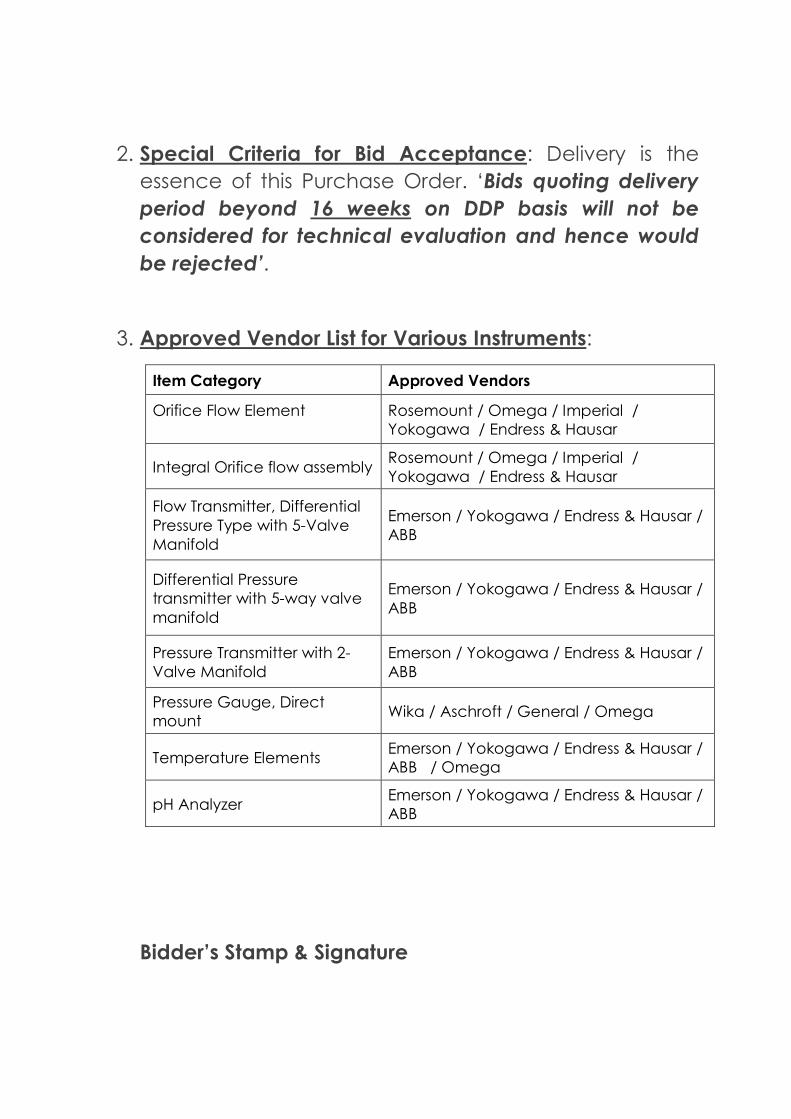
2. Special Criteria for Bid Acceptance: Delivery is the
essence of this Purchase Order. ‘Bids quoting delivery
period beyond 16 weeks on DDP basis will not be
considered for technical evaluation and hence would
be rejected’.
3. Approved Vendor List for Various Instruments:
Item Category Approved Vendors
Orifice Flow Element
Rosemount / Omega / Imperial /
Yokogawa / Endress & Hausar
Integral Orifice flow assembly Rosemount / Omega / Imperial /
Yokogawa / Endress & Hausar
Flow Transmitter, Differential
Pressure Type with 5-Valve
Manifold
Emerson / Yokogawa / Endress & Hausar /
ABB
Differential Pressure
transmitter with 5-way valve
manifold
Emerson / Yokogawa / Endress & Hausar /
ABB
Pressure Transmitter with 2-
Valve Manifold
Emerson / Yokogawa / Endress & Hausar /
ABB
Pressure Gauge, Direct
mount Wika / Aschroft / General / Omega
Temperature Elements Emerson / Yokogawa / Endress & Hausar /
ABB / Omega
pH Analyzer Emerson / Yokogawa / Endress & Hausar /
ABB
Bidder’s Stamp & Signature
09004ed58008dbef____A4____.doc
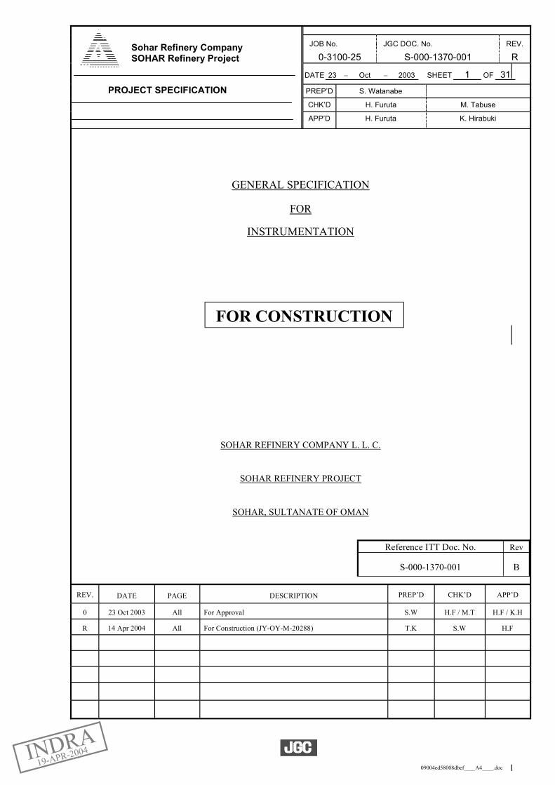
JOB No. JGC DOC. No. REV.
0-3100-25 S-000-1370-001 R
DATE 23 Oct 2003 SHEET 1 OF 31
PREP’D S. Watanabe
CHK’D H. Furuta M. Tabuse
APP’D H. Furuta K. Hirabuki
GENERAL SPECIFICATION
FOR
INSTRUMENTATION
SOHAR REFINERY COMPANY L. L. C.
SOHAR REFINERY PROJECT
SOHAR, SULTANATE OF OMAN
Reference ITT Doc. No. Rev
S-000-1370-001 B
REV. DATE PAGE DESCRIPTION PREP’D CHK’D APP’D
0 23 Oct 2003 All For Approval S.W H.F / M.T H.F / K.H
R 14 Apr 2004 All For Construction (JY-OY-M-20288) T.K S.W H.F
PROJECT SPECIFICATION
Sohar Refinery Company SOHAR Refinery Project
FOR CONSTRUCTION
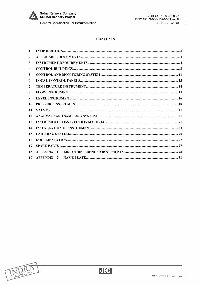
JOB CODE: 0-3100-25Sohar Refinery Company SOHAR Refinery Project
DOC NO: S-000-1370-001 rev.R General Specification For Instrumentation SHEET : 2 of 31
09004ed58008dbef____A4____.doc
CONTENTS
1 INTRODUCTION......................................................................................................................................... 3 2 APPLICABLE DOCUMENTS .................................................................................................................... 3 3 INSTRUMENT REQUIREMENTS............................................................................................................ 4 4 CONTROL BUILDINGS ............................................................................................................................. 8 5 CONTROL AND MONITORING SYSTEM ........................................................................................... 11 6 LOCAL CONTROL PANELS................................................................................................................... 13 7 TEMPERATURE INSTRUMENT............................................................................................................ 14 8 FLOW INSTRUMENT .............................................................................................................................. 15 9 LEVEL INSTRUMENT ............................................................................................................................. 16 10 PRESSURE INSTRUMENT...................................................................................................................... 18 11 VALVES ...................................................................................................................................................... 21 12 ANALYZER AND SAMPLING SYSTEM............................................................................................... 21 13 INSTRUMENT CONSTRUCTION MATERIAL ................................................................................... 21 14 INSTALLATION OF INSTRUMENT...................................................................................................... 23 15 EARTHING SYSTEM................................................................................................................................ 26 16 DOCUMENTATION.................................................................................................................................. 27 17 SPARE PARTS ........................................................................................................................................... 27 18 APPENDIX – 1 LIST OF REFERENCED DOCUMENTS ............................................................... 28 19 APPENDIX – 2 NAME PLATE............................................................................................................ 31
JOB CODE: 0-3100-25Sohar Refinery Company SOHAR Refinery Project
DOC NO: S-000-1370-001 rev.R General Specification For Instrumentation SHEET : 3 of 31
09004ed58008dbef____A4____.doc
1 INTRODUCTION 1.1 PURPOSE
The purpose of this specification, together with the Licensor standard specifications, drawings, Industrial codes and standard, is to define the general requirements for instrumentation for Sohar Refinery Project.
1.2 SCOPE
This specification provides the general instrument requirements for the project. For more detailed information, the relevant project specifications and Licensers’ documents shall be referred to.
1.3 CONFLICTS and DEVIATIONS
If any inconsistency or conflict exists between this specification and other Licensors’ documents, industrial standards or drawings, the following precedence will be applied: (1) Governmental or Local Authority regulations. (2) General Specification for Instrumentation (S-000-1370-001). (3) Other Instrument Specifications as referenced in this Specification, listed below. (4) Licensors’ documents as part of the Project Specification. (5) Industrial International Codes and Standards. Where a conflict between the above documents might exist, the conflict shall be brought to Owner. Owner shall resolve the conflict in case by cases.
2 APPLICABLE DOCUMENTS 2.1 The following documents shall apply as a part of the instrument design and engineering basis together
with this specification.
- S-000-1370-002 Instrument and Control Philosophy - S-000-1371-001 Specification for DCS - S-000-1371-002 Specification for ESD and FGS - S-000-1371-004 Product Blending Control System - S-000-1371-005 Specification for Online ESD Valve Testing - S-000-1371-201 Specification for Cabinet and Rack Design - S-000-1372-001 Specification for Integrated Control and Information Management System (ICIMS) - S-000-1374-101 General specification for Control valves - S-000-1374-201 General specification for On-off valves - S-000-1375-001 Specification of Analyzers - S-000-1377-002 Specification for Metering System
- UOP licensing documents - TECHNIP licensing documents for Hydrogen Generation Unit (GHU) - STORK licensing documents for Sulfur Recovery, Tail Gas Treating Unit (SRU and TGU) - IFP issued documents for Total’s Selective Hydrogenation Process Unit and Gasoline HDS Unit
(TSHP and GHDS) - NESTE issued documents for TAME unit (TAME) - Other industrial Codes and Standards such as API, ISA etc. referred to in this specification
2.2 The latest edition of the standards as of 19 May 2003 shall be applied unless otherwise specified.
Standards, codes, standard drawings and specifications referred to in this specification are listed on Appendix 1 "List of Referenced Documents". Abbreviations for the standard are as listed below.
JOB CODE: 0-3100-25Sohar Refinery Company SOHAR Refinery Project
DOC NO: S-000-1370-001 rev.R General Specification For Instrumentation SHEET : 4 of 31
09004ed58008dbef____A4____.doc
AGA American Gas Association AISI American Iron and Steel Institute ANSI/ASME American National Standards Institute/American Society & Mechanical
Engineering API American Petroleum Institute ASTM American Society for Testing and Material BASEEFA British Approvals Service for Electrical Equipment in Flammable Atmospheres BS British Standard CENELEC European Committee for Electrotechnical Standardization DIN Deutsches Institute für Normung EEMUA Engineering Equipment and Material Users Association EIC Energy Industrial Council FCI Fluid Controls Institute FM Factory Mutual IEEE Institute of Electrical Electronic Engineers IEC International Electrotechnical Commission IP Institute of Petroleum ISA The Instrumentation, Systems and Automation Society ISO International Organization for Standardization JIS Japanese Industrial Standard NACE National Association of Corrosion Engineering NEC National Electric Code NEMA National Electrical Manufacturers Association NESC National Electrical Safety Code NFPA National Fire Protection Association UL Underwriter’s Laboratories
3 INSTRUMENT REQUIREMENTS 3.1 GENERAL 3.1.1 Installation environment
Instruments shall be suitable for installation in the climatic conditions specified below and shall be tropicalised as per the manufacturer standard procedure. All parts subject to dust, moisture, insect, corrosion, etc. shall be treated with a suitable coating to inhibit such corrosive attack. A sunshade (304 stainless steel) or a suitable cooler shall be provided where the instrument, local panels, etc. are exposed to direct sunlight. Pneumatic instruments (actuators), gauges, etc. do not require a sunshade. (1) Ambient design temperature - max ./ min. : 47.5 (dry bulb temp.)/ 5 deg C
Min. record temperature is 3.5 degC shall be used for examination the impact to transportation with high pour point field. It shall be considered that the ambient temperature does exceed the design temperature in particular when exposed to direct sunlight.
(2) Relative humidity - max. / min. : 100/ 6 %
(3) Maximum wind - 22.9 m/sec Wind direction - NNW
(4) Barometric pressure - max. /min. : 1026/ 990 mbar
(5) Earthquake - Nil
(6) Location - Sea Coast

JOB CODE: 0-3100-25Sohar Refinery Company SOHAR Refinery Project
DOC NO: S-000-1370-001 rev.R General Specification For Instrumentation SHEET : 5 of 31
09004ed58008dbef____A4____.doc
3.1.2 Electrical hazardous classification The basis for area classification shall be in accordance with the provisions of the IEC. All outdoor electrical instrumentation shall be certified for the area classification. (1) All electrical devices, electronic instrumentation and wiring shall be suitable for installation in
the relevant electrical area classification. (2) Equipment located in hazardous area shall be certified by internationally recognized
organizations to LCIE, INERIS, TIIS, EECS, FM, UL, PTB, BASEEFA, KEMA, etc. The use of other nationally accepted standards shall be subject to approval by Contractor.
(3) When the hazardous areas are classified, instruments shall be EExi or Exi type. Other type of
protection, such as EEx”d” and EEx”n”, shall be used by exceptions, and require Owner approval. All outdoor electrical instrumentation located in non-hazardous areas shall be suitable for a zone 2 area, minimum gas group IIC and temperature class T3. Instead of certification, use of manufacturer's declaration on basis of IEC 60079.14 in zone 2 areas may be used in special cases, subject to Owner approval. EEx”i” instrumentation in non-hazardous areas are not required to utilize barriers.
(4) Purged and pressurized air protection stipulated by NFPA, BS, etc. can be applied for
enclosures such as local panels in hazardous location.
(5) Instruments type of protection for Fire and Gas System (FGS) shall be Ex”d” or EEx”d” type. 3.1.3 All outdoor electrical instruments, local panels and Junction Boxes (J.B) shall be NEMA 4X or IP 55
as minimum. Requirements for protection of equipment against direct sunlight shall be assessed at site by Contractor and Sub-contractor.
3.1.4 One style of tube fittings, i.e. double ferrule type compression fitting, shall be selected and used
through-out the plant, e.g. Parker Hannifin or equivalent with Owner’s approval. 3.1.5 As a minimum, all wetted parts of instrumentation shall be 316SS, unless specified differently in the
instrument specification sheets. 3.1.6 Instrument installation will be per API RP 551 (1993). All process connections shall have a piping
root valve. 3.1.7 All equipment and materials shall be new and supplied from the approved instrument vendor list.
Many duplicated items existing in the market should be avoided. 3.1.8 All instrument systems (Control, Monitoring and ESD systems) shall be provided from the latest field
proven product line at the time of purchase order issue. Use of equipment manufactured with unknown standards shall be avoided. The latest debugged software version shall be applied at the time of frozen detailed design, and the latest debugged software release shall be used during installation and commissioning.
3.1.9 Signal transmission
(1) Pneumatic instruments shall have a standard air signal of 0.2 to 1.0 barg.
(2) Electric instrument signals shall be 4 to 20 mA DC except some level instruments (e.g. tank gauges), positive displacement meters, turbine meters and quality analyzers, etc.
(3) Instrument circuit shall be 24VDC.
3.1.10 Air supply and output gauges shall be provided for all instruments consuming air. 3.1.11 Filter regulator assembly shall be provided for all instruments requiring an air supply and shall be
designed for 4-11 barg inlet air pressure.
JOB CODE: 0-3100-25Sohar Refinery Company SOHAR Refinery Project
DOC NO: S-000-1370-001 rev.R General Specification For Instrumentation SHEET : 6 of 31
09004ed58008dbef____A4____.doc
3.1.12 All automatic-manual air transfer switches shall be integrally mounted, preferably internally. They shall be 4 positions for large case (conventional type) instruments. Miniature pneumatic and electronic controllers shall have the number of switch positions required for bumpless transfer from automatic to manual control and vice-versa.
3.1.13 All field transmitters shall be SMART type of 4-20 mA with HART communication protocol except
for service where the high speed response is required, non-smart type transmitters should be used,e.g. for the compressor anti-surge control that is subject to approval by Owner. All transmitters shall have an integral digital indicator. 10 handheld terminals for the HART instruments shall be provided which will be used during commissioning, installation and maintenance.
3.1.14 24 VDC shall be used for trip or sequential initiation or activation device. 3.1.15 Lighting and sockets in Supplier panels or cabinets, if necessary, shall be powered from Non-UPS at
240VAC, 50 Hz single phase. All other instruments shall be powered from UPS at 240VAC, 50Hz single phase. Where the panels or field circuits require lower voltage levels, these shall be generated via power supply units provided as part of the package. Emergency lighting will be provided outside of local cabinets.
3.1.16 All panel circuits shall be suitably protected against over current, with suitable isolation as necessary
for testing and maintenance. All external circuits powered by the equipment shall be individually isolated and protected at source.
3.1.17 All wiring and cable cores shall be suitably identified at the terminal points, e.g. ferruling. The
identification system is described in D-000-1378-001 “Instrument Typical Installation”. 3.1.18 Terminal blocks with “Weidmuller SAK series” disconnect type and a fuse for each signal shall be
provided inside panels and all wirings to/ from the panel shall be terminated on these terminal blocks. At least 20% spare terminals shall be provided with any instrument panels/cabinets, junction boxes and local panels.
3.1.19 All relays installed in outdoor local panels or boxes shall be hermetically sealed type or gold plated
contact type. 3.1.20 Factory acceptance test (FAT)
Owner will attend the following FAT: (1) DCS (2) ESD (3) Fire and Gas System (FGS) (4) Metering Systems (5) Tank Gauge Systems (TGS) (6) MOV Systems (7) Analyzers (8) Truck Loading Automation Systems (TLAS) (9) Compressor Control System including Anti-Surge Controller (10) Control Valves (11) ESD Valve Testing System
3.1.21 Control and trip devices shall not share the same measurement bridle where the process fluid has a
risk of fouling. 3.1.22 Generally all trip transmitters shall have or shall be provided with a corresponding process control
transmitter to enable automatic comparison in DCS. Exceptions shall be subject to Owner approval, such as 2 out of 3 voting arrangement. In principle trip transmitters shall have the same range and accuracy as neighboring control transmitters, except of those for level. In all cases HH level trip transmitters and LL level trip transmitters in liquid/liquid interfaces shall have a narrower range than the control transmitter. The range for low flow protection (LL flow trip) shall be designed for the low delta-P during low flow rate and not for the higher delta-P during normal operation. For more detail on transmitters comparison,
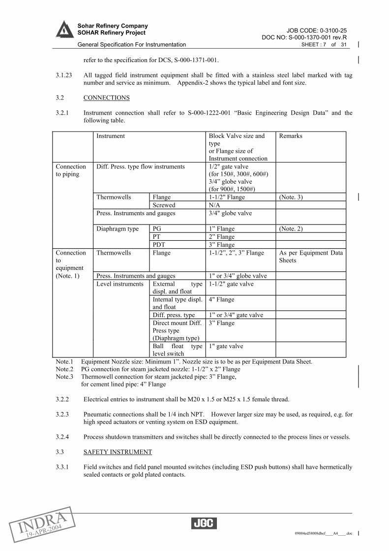
JOB CODE: 0-3100-25Sohar Refinery Company SOHAR Refinery Project
DOC NO: S-000-1370-001 rev.R General Specification For Instrumentation SHEET : 7 of 31
09004ed58008dbef____A4____.doc
refer to the specification for DCS, S-000-1371-001.
3.1.23 All tagged field instrument equipment shall be fitted with a stainless steel label marked with tag number and service as minimum. Appendix-2 shows the typical label and font size.
3.2 CONNECTIONS 3.2.1 Instrument connection shall refer to S-000-1222-001 “Basic Engineering Design Data” and the
following table. Instrument Block Valve size and
type or Flange size of Instrument connection
Remarks
Connection to piping
Diff. Press. type flow instruments 1/2" gate valve (for 150#, 300#, 600#) 3/4” globe valve (for 900#, 1500#)
Thermowells Flange 1-1/2" Flange (Note. 3) Screwed N/A Press. Instruments and gauges 3/4" globe valve
Diaphragm type PG 1” Flange (Note. 2) PT 2” Flange PDT 3” Flange Connection to equipment
Thermowells Flange 1-1/2”, 2”, 3” Flange As per Equipment Data Sheets
(Note. 1) Press. Instruments and gauges 1" or 3/4” globe valve Level instruments External type
displ. and float 1-1/2" gate valve
Internal type displ. and float
4" Flange
Diff. press. type 1” or 3/4" gate valve Direct mount Diff.
Press type (Diaphragm type)
3” Flange
Ball float type level switch
1" gate valve
Note.1 Equipment Nozzle size: Minimum 1”. Nozzle size is to be as per Equipment Data Sheet. Note.2 PG connection for steam jacketed nozzle: 1-1/2” x 2” Flange Note.3 Thermowell connection for steam jacketed pipe: 3” Flange, for cement lined pipe: 4” Flange 3.2.2 Electrical entries to instrument shall be M20 x 1.5 or M25 x 1.5 female thread. 3.2.3 Pneumatic connections shall be 1/4 inch NPT. However larger size may be used, as required, e.g. for
high speed actuators or venting system on ESD equipment. 3.2.4 Process shutdown transmitters and switches shall be directly connected to the process lines or vessels.
3.3 SAFETY INSTRUMENT 3.3.1 Field switches and field panel mounted switches (including ESD push buttons) shall have hermetically
sealed contacts or gold plated contacts.
JOB CODE: 0-3100-25Sohar Refinery Company SOHAR Refinery Project
DOC NO: S-000-1370-001 rev.R General Specification For Instrumentation SHEET : 8 of 31
09004ed58008dbef____A4____.doc
3.3.2 All ESD alarms and shutdown switches shall be fail safe, i.e., switch contacts are closed at healthy plant condition and open to generate an alarm or shutdown. The status switch contacts are to be normally opened and closed to indicate status.
3.4 Unit and Scale
The units of measurement shall be Metric. Each engineering unit and measurement scale etc. shall be in accordance with instrument data sheet.
(1) Flow: Flowing Quantities
kg/h for mass m3/h for liquids kg/h, ton/h for steam
Standard Quantities Sm3/h for liquids (at 15°C and 1.013 bara) Nm3/h for vapor (at 0°C and 1.013 bara) (2) Level: % (percent of range)
(3) Pressure: barg for gauge pressure
bara for absolute pressure mbarg or mbara for low pressure bar or mbar for differential pressure (4) Temperature: °C (5) Other: Consult with Contractor
3.5 Accuracy
Unless otherwise stated, the accuracy of instruments shall be as follows: (1) Temperature gauge: +/-1.5 % of full scale (2) Electronic transmitter: +/-0.5 % of full scale (3) Pneumatic transmitter: +/- 1.5 % of full scale
3.6 Available utilities The available utilities with process conditions, such as plant air, steam and water etc., are described in S-000-1222-001 “Basic Engineering Design Data”.
4 CONTROL BUILDINGS 4.1 General
The instrument control and monitoring system (with DCS operator consoles and Man Machine Interface, MMI) will be installed in the following control buildings. (1) Main Control Building: MCB (2) Jetty Office (w/SS-31 & SIH-5): SIH-5 (3) Truck Loading Control Building (w/SS-23 & SIH-6): SIH-6
The instrument control and monitoring system (without DCS operator consoles and MMI) will be installed in the following buildings.
JOB CODE: 0-3100-25Sohar Refinery Company SOHAR Refinery Project
DOC NO: S-000-1370-001 rev.R General Specification For Instrumentation SHEET : 9 of 31
09004ed58008dbef____A4____.doc
(4) SIH-1 for Process Area-1 & 2: SIH-1 (5) SIH-2 for Process Area-3 & 4: SIH-2 (6) SIH-3 for Utility area: SIH-3 (7) Tankage Area Substation (w/SS-21 & SIH-4): SIH-4
The control system installed in these buildings will be linked with suitable communication network, i.e. extension of DCS redundant data highway, Ethernet or serial communication link etc.
The allocation of process units, utility units, off site units to these control buildings are described as follows. The detail shall be referred to D-000-1371-001 “DCS/ESD/FGS System Configuration”.
4.2 Main Control Building, SIH-1, SIH-2, SIH-3 and SIH-4
The main control building shall be used as the operational center for process units, utility units and off-site units. The equipment layout in main control building is shown in D-000-1378-201. The DCS, ESD, FGS, Plant Information Management System, other subsystem, communication system (e.g. CCTV, Paging, radio, telephone) etc., associated auxiliary panels/consoles, instrument power distribution panels and a UPS etc. will be installed in the main control building.
(1) The DCS and ESD system in MCB/SIH-1/SIH-2/SIH-3/SIH-4 will control and monitor the
following facilities. SIH-1 Unit 1100 Crude Distillation Unit (CDU) Unit 1200 CDU LPG Merox Process Unit (CDU LPG MEROX) Unit 1300 CDU Kerosene Merox Process Unit (KEROSENE MEROX) Unit 2000 Resid FCC Reactor Regeneration Section (RFCC RXRG) Unit 2100 Resid FCC Main Fractionation Section (RFCC MF) Unit 2200 Resid FCC Gas Concentration Section (RFCC GC) Unit 2300 Resid FCC Flue Gas Section (RFCC FLG) Unit 2600 Resid FCC LPG Merox Process Units (RFCC LPG Merox) Unit 2700 Propylene Recovery Unit (PRU) Unit 6500 Part of Waste Water Treatment SIH-2 Unit 3200 Distillate Unionfining Process Unit (DHDS) Unit 4000 TAME Selective Hydrogenation Process Unit (TSHP) Unit 4200 Gasoline HDS Unit (GHDS) Unit 3300 Hydrogen Generation Unit (HGU) Unit 3400 Sour Water Stripping Unit (SWS) Unit 3500 Amine Regeneration Unit (ARU) Unit 3600 Sulfur Recovery Unit Train 1 (SRU1) Unit 3650 Sulfur Recovery Unit Train 2 (SRU2) Unit 3700 Tail Gas Treating Unit (TGU) SIH-3 Unit 2800 Huels Selective Hydrogenation Process Unit (SHP) Unit 2900 Indirect Alkylation Unit (InAlk) Unit 4100 TAME Unit (TAME) Unit 5100 Power Plant, Electricity and Distribution System Unit 5200 Sea Water Intake Station Unit 5300 Water System Unit 5310 Cooling Water System Unit 5320 Sea Water Desalination Unit 5340 Portable and Service Water Unit 5400 Steam and Condensate System (STM) Unit 5500 Fuel Gas and Natural Gas Supply System (FG) Unit 5600 Instrument and Plant Air System (IA & PA) Unit 5700 Nitrogen System (N2) (by others) Unit 5800 Chemical Preparation and Injection Package Facilities Unit 5900 Flushing Oil System
JOB CODE: 0-3100-25Sohar Refinery Company SOHAR Refinery Project
DOC NO: S-000-1370-001 rev.R General Specification For Instrumentation SHEET : 10 of 31
09004ed58008dbef____A4____.doc
SIH-4 Unit 6100 Feedstock and Slop Tankage Unit 6200 Product and Component Tankage MCB Unit 6900 Flare System
(2) MCB/SIH-4 serves as the process control & monitoring, ESD and Fire & Gas system for the
above offsite facilities, Metering systems and other subsystems.
The DCS, ESD, F&G system, sub control systems (MOV, Tank Gauging System, etc.) and marshalling racks, associated panels and a UPS will be installed in this SIH. Note) The blending control for gasoline shall be configured by DCS or a dedicated computer. The further information will be provided in S-000-1371-004 “Product Blending Control System”.
(3) Weather monitoring instruments, i.e. wind speed and direction, ambient temperature and relative humidity will be installed at Main Control Building.
4.3 Jetty Office (SIH-5)
The marine control SIH is located at jetty and serve as control and monitoring ESD, and Fire & Gas system for Marine Loading Facilities (Unit 6400).
The DCS, ESD, Fire &Gas system, Loading /unloading arms control system, MOV system etc, marshalling racks, associated panels and a UPS will be installed. The DCS operator stations will be installed.
The equipment layout in marine control building is shown in D-000-1378-206.
4.4 Truck Loading Building (SIH-6)
The truck loading building SIH serves as the control & monitoring and FGS for following facilities, Truck Loading Automation System (TLAS) and other systems. Unit 3800 Sulfur Granulation Unit (SGU) Unit 6300 Truck Loading Facilities Unit 6500 Waste Water Treatment The DCS, FGS, Truck Loading Automation system, marshalling racks and a UPS etc. will be installed in this building. The DCS operator stations will be installed.
4.5 Instrument requirements for inside the control buildings 4.5.1 General
(1) Inside of the control buildings can be considered as safe area and under air-conditioned environment.
(2) The instruments installed in control buildings shall be mounted in auxiliary cabinets, racks or
on auxiliary consoles as required. Cabinet design and wiring colors shall be in accordance with S-000-1371-201 “Specification for Cabinet and Rack Design”.
(3) For DCS cabinets, operator consoles and ESD cabinets, manufacturer’s standard shall be
applied.
(4) Consideration shall be given for the uniformity in appearance for these cabinets, racks and consoles.
(5) All cabinets/racks etc. shall have bottom cable entries. Bottom plates shall be removable for
JOB CODE: 0-3100-25Sohar Refinery Company SOHAR Refinery Project
DOC NO: S-000-1370-001 rev.R General Specification For Instrumentation SHEET : 11 of 31
09004ed58008dbef____A4____.doc
cable installation. Steel bar(s) shall be provided to fix the external cables at the bottom. The mounting arrangements for cabinets shall take into account the sealing requirements for the extinguishing gas system below the raised floor.
(6) Maximum use should be made of plug and socket connections between the cabinets.
(7) The free access raised floor shall be provided for installation of cabinets and consoles.
(8) Redundant ventilation fans shall be installed where it is required for cabinets and racks. (9) To have uniformity the standard cabinet size for System cabinets, Auxiliary cabinets,
Marshalling racks, I/E Interface cabinets, Unit Control Panels, etc., S-000-1371-201 “Specification for Cabinet and Rack Design” shall be referred to.
4.5.2 Auxiliary Cabinets
The requirements for auxiliary cabinets shall be referred to S-000-1371-201 “Specification for Cabinet and Rack Design”.
4.5.3 Marshalling Racks
The requirements for marshalling racks shall be referred to S-000-1371-201 “Specification for Cabinet and Rack Design”.
(1) Lightning arrestors shall be provided for some instruments in off-site and utility area which are
not protected by any other means (i.e. not protected by structure etc.). Consideration shall be given to transient protection within some transmitters in these area, too.
4.5.4 Instrument and Electrical (I/E) interface cabinets
(1) MCC/DCS status signals, (running, available, current), shall be sent via single or redundant serial link. Operator start/stop signals shall be sent via redundant serial link. Start/stop signals for automatic take-over functionality of pumps/motors shall be hardwired to the interposing relays installed in the I/E interface cabinets. The shutdown signals from the ESD system shall be hardwired to the interposing relays installed in the I/E Interface cabinets. These cabinets will be installed in the associated substations.
5 CONTROL AND MONITORING SYSTEM 5.1 Distributed Control System (DCS) 5.1.1 General
The DCS shall provide the principal operating window for the plant. It shall contain microprocessor based fully redundant controllers with I/O devices, operator interface, data storage, printers and other auxiliary equipment.
Field devices will be hard wired to the DCS via marshalling racks. The DCS shall receive redundant power supply of 240Vac from a UPS with 30 minutes backup as minimum. The detailed requirements are described in S-000-1371-001 “Specification for DCS”.
5.1.2 Subsystem communication with DCS
The data transferred between DCS and Subsystems will be hardwired and/or serial communication link. In principal, the shutdown, interlock and control related signals shall be hardwired. The monitoring signals should be through serial communication.
JOB CODE: 0-3100-25Sohar Refinery Company SOHAR Refinery Project
DOC NO: S-000-1370-001 rev.R General Specification For Instrumentation SHEET : 12 of 31
09004ed58008dbef____A4____.doc
The detail shall be referred to S-000-1370-002, “Instrument and Control Philosophy”. 5.1.3 Blending control
The blending control will be configured by the DCS. The detailed specification of blending control system is described in S-000-1371-004.
5.1.4 Integrated Control and Information Management System (ICIMS)
ICIMS is described in S-000-1372-001. 5.1.5 Packaged unit control and monitoring
Packaged units will be controlled and monitored by a Unit Control Panel (UCP), supplied by the Vendor, or the DCS/ESD supplied by Contractor. The provision of primary control system of packaged units is described in S-000-1370-002 “Instrument and Control Philosophy”. Utilization of proprietary control and protection systems designed and manufactured by the Vendors, such as Gas/Steam Turbine Controller, Anti-Surge Controller (ASC), Vibration Monitoring System (VMS), and Burner Management System (BMS) will be defined in the relevant requisition and specification for the packaged unit.
5.2 ESD system 5.2.1 General
Shutdown logic and Depressurization shall be configured by fully redundant PLC basis system with TUV AK-6 certification as minimum. This system shall be independent from normal operational control system (i.e. DCS). The status monitoring for the shutdown system shall be through DCS via redundant serial links or connected with DCS data highway by redundant communication modules. Online ESD valve test function shall be provided. The detailed requirements are described in S-000-1371-005 “Specification for Online ESD Valve Testing”. The protective measures of ESD system shall include, but not necessarily be limited to, the following:
(1) Protection against over pressuring (2) Protection against over heating (3) Protection of uncontrolled chemical reaction (4) Protection against abnormal liquid levels (5) Activation of depressurization systems (6) Isolation/removal of liquid inventories contained in vessels (7) Prevention of flammable or toxic material atmospheric release (8) Prevention damage to equipment
5.2.2 The ESD system design shall be fail safe. 5.2.3 The ESD shall include a PC based sequence of event recorder (SER) with a printer for logging status
all input, output, override and resets. Operational override switches (OOS) and maintenance override switches (MOS) function will be configured by DCS software and be activated from DCS.
The detailed requirements are described in S-000-1371-002 “Specification for ESD”.
5.2.4 The ESD system shall receive the redundant power supply of 240VAC from a UPS with 30 minutes
back up as minimum. The output of shutdown circuit shall be 24 VDC. Outputs shall be “de-energized to trip”.
5.2.5 The shutdown of sub systems, which have dedicated PLC or relay based control and shutdown system,
will be performed by its own shutdown system. The ESD system shall give a hardwired shutdown command to these subsystems.
5.2.6 The ESD system shall shutdown motor control circuits in substations by hardwired signal via Instrument/ Electric (I/E) interface cabinets installed in associated substations.
JOB CODE: 0-3100-25Sohar Refinery Company SOHAR Refinery Project
DOC NO: S-000-1370-001 rev.R General Specification For Instrumentation SHEET : 13 of 31
09004ed58008dbef____A4____.doc
5.3 Fire and Gas system 5.3.1 General
Fire and Gas System (FGS) shall be provided for detection of fire and gas release. FGS for Process areas, (outside of buildings), shall be of the same make and type as the ESD System, redundant PLC's, TUV AK-6 certified. The system will be non-addressable. Location of system cabinets will be in MCB and SIHs. Separate systems for Gas detection and Fire detection are not required. The FGS shall perform fire fighting and control actions as well as indications for Fire/Gas Mimic panels (Plasma display). This system will provide audible and visual alarm indication in the Process areas. All Fire & Gas signals and alarms shall be sent over the redundant serial links to the DCS for primary DCS operator interface. For inside of buildings, a commonly used industrial type addressable fire detection system will be used. Building fire detection systems will provide the audible and visual fire alarms for the areas within the respective building. These systems will provide common fire alarms and common fault (etc.) alarms to the Fire & Gas System for Process areas (hardwired). Individual fire and gas alarms shall be displayed on the DCS. Common fire and gas alarms shall be provided on Mimic panels (Plasma display). Manual controls for FGS shall be provided on the operator console installed in Main control room (in MCB) and Jetty control room (in SIH-5). The operator console (in MCB) shall also include start push buttons and status indicators for the flesh water and sea water fire pumps. Monitoring PCs for individual fire and gas alarm shall be provided in the fire station and the control room (in MCB). The de-centralized battery concept shall be used, which provide backup power to FGS for minimum 4 hours. FGS outputs are contact closed to activate with line monitoring. FGS inputs for contacts are normally open, close to alarm with EOL resistors for line monitoring. The H2S horns and beacons shall have contact to close to activate. The H2S and LEL sensor shall have a horn and beacon located in the respective area. The further requirements are described in S-000-1370-002 “Instrument and Control System Philosophy” and S-000-1371-002 “Specification for ESD and FGS Systems”.
6 LOCAL CONTROL PANELS 6.1 Local panels shall be enclosed, self-supporting cubicle type panels, suitably gasketted to render them
dust and moisture proof. Sunshades/weather hoods shall be provided over local panels, which are exposed to direct sunshine or raining. Sunvisor over annunciater lamps shall be considered to prevent glare on the lamps. The minimum degree of protection is IP55 or NEMA 4X for outdoor mounted equipment. The local panel shall be made of anti-corrosion painted carbon steel or stainless steel. The anti corrosion paint shall be comply with the project painting specification.
6.2 Where the size of the cubicle would be disproportionate to the requirement, open panels with weather
protective cover should be considered, e.g. 3-side shelter, etc. 6.3 Instruments with direct process connections should be fitted in sections of the panel separate from
those containing electrical and pneumatic instruments.
JOB CODE: 0-3100-25Sohar Refinery Company SOHAR Refinery Project
DOC NO: S-000-1370-001 rev.R General Specification For Instrumentation SHEET : 14 of 31
09004ed58008dbef____A4____.doc
6.4 Electrical switchgear, (e.g. contactors), shall not be fitted in sections of the panel containing instrumentation and control equipment.
6.5 Each piece of panel mounted instrument shall be wired or tubed to suitable terminals mounted in the
panel. Separate terminal boxes shall be provided for each type of signal and power. Separate terminal boxes shall also be provided for ESD signals.
6.6 Where local panels contain relay and/or alarm logic system, consideration shall be given to the
climatic conditions. The relays in a local panel shall be hermetically sealed type or gold plated contact type.
6.7 All instruments mounted on the local panel shall have individual nameplates. Labels shall be made
of stainless steel and fitted by means of screws or adhesives. On front of panel, name plate labels shall identify instrument tag number and duty. On rear of panel, labels shall identify instrument tag number only. Abbreviation shall be in accordance with ISA RP 60.6.
6.8 Anti-condensation heaters controlled by thermostat or vortex tube cooler should be provided within
the panel unless the panel is located in an air conditioned environment or all equipment mounted in panel to be suitably tropicalized. External emergency lightning shall be provided on the local control panel for maintenance or operation, if required.
6.9 If a Local (Control) Panel contains lamps/indicators, a push-button for "lamp-test" shall be included in
the panel design. 7 TEMPERATURE INSTRUMENT 7.1 Temperature instrument shall be designed in accordance with API RP 551 and data sheets for each
temperature instrument with the following additions and options. 7.2 Transmission shall be by the application of direct head mounted type smart transmitters (4-20 mA). 7.3 The smart type transmitters shall be provided except for the bearing temperature and motor winding
temperature measurement for compressors and pumps. The bearing and winding temperature signals with RTD shall be directly connected to its related temperature monitors.
7.4 Unless otherwise stated, PT 100 ohm RTD element with 3 wires to IEC60751 shall be used where the
measuring temperature is 450 deg C and below. Type-K thermocouple shall be used where the temperature is above 450 deg C. Skin temperature shall be type-K.
7.5 For thermocouple of measuring temperature above 1100 deg C, or H2 service above 750 degC, care
shall be taken for the sheath material selection. 7.6 Multipoint temperature indication for reactors, etc., shall be achieved via the DCS. 7.7 Thermocouple and RTD circuits operating high temperature alarms shall have upscale element
burn-out. Those on low temperature alarms shall fail to down scale position. 7.8 Thermowell shall be designed in accordance with UOP standard drawing 6-105-4 “Thermowells” and
6-106-3 “Thermometer assembly”, except for the flange size.
JOB CODE: 0-3100-25Sohar Refinery Company SOHAR Refinery Project
DOC NO: S-000-1370-001 rev.R General Specification For Instrumentation SHEET : 15 of 31
09004ed58008dbef____A4____.doc
7.9 Karman vortex effect shall be calculated where it is required and thermowell shall have enough strength against it. Standard flanged thermowell size of 1-1/2 inch shall be used. At high fluid velocity, a shorten immersion length themowell or 2 inch thermowell design shall be used, and if required, a collared thermowell design may be applied. Thermowells shall be calculated for vibration and stress according to ASME Performance Test Code (PTC) 19.3.
7.10 Thermocouple head terminals shall be marked with positive and negative symbols.
The head shall be protected to IP55 or NEMA 4X as minimum.
7.11 The range of any temperature measuring instrument shall be the manufacturer’s narrowest standard span appropriate to the application. For local indicators, the following standard ranges are preferred: -20 to + 60 degC -0 to + 160 degC -0 to + 250 degC -0 to + 400 degC Scale ranges shall be selected such that the normal temperature shall be indicated within 30-70% of the range.
8 FLOW INSTRUMENT 8.1 General
The flow instrument shall be designed in accordance with API RP 551, UOP standard specification 6-18-1 “Flow Meters and Pressure Instruments” and data sheets for each flow instrument with following additions. The design and construction requirements for fiscal or commercial custody transfer flow metering systems are specified in S-000-1377-002 “Specification for Metering System”. The calculations for fiscal or commercial custody transfer flow meter shall follow the principles of API Manual of Petroleum Measurement Standards Chapter 2. The body of flow meters shall be suitably marked with the direction of flow. Inline or closed coupled (direct flanged) flow instruments are part of mechanical engineering, therefore material selection/examination, welding, treatments, testing, marking, certification, etc. shall apply with the project piping specifications and documents. To enable correct operation and service of flow device and flow meter, a typical installation requirements shall be prepared for flow meters. Any issue shall be highlighted as straight run length requirements per flow meter type and size, preferred transmitter positions, etc. Special delivery requirements as earthing rings, packing material, etc. should be included as well.
8.1.1 Bore calculation for orifice plates shall be in accordance with ISO 5167. For those items that fall outside of ISO 5167, the equations from ASME MFC-14M or the Flow Measurement Engineering Handbook (by Richard Miller) may be used. The design and construction requirement of orifice plates shall be in accordance with UOP standard specification 6-18-1 “Flow meters and Pressure instruments” and UOP standard drawing 6-111-4 “Orifice plates”, or ISO 5167.
8.1.2 The tapping for orifice plates shall be designed in accordance with API RP 550/551, unless otherwise
specified in the licenser data sheets, i.e. the orientation of the tapping on horizontal line shall be generally as follows:
Gas Service: Vertical (Top) or 45 Upward Liquid Service: Horizontal or 45 Downward Steam Service: Horizontal or 45 Upward
JOB CODE: 0-3100-25Sohar Refinery Company SOHAR Refinery Project
DOC NO: S-000-1370-001 rev.R General Specification For Instrumentation SHEET : 16 of 31
09004ed58008dbef____A4____.doc
Whenever a control function and a trip function are combined in one single primary flow measurement element, individual flow transmitters shall be installed (individual tapping connections on the orifice flange). The pressure lead tapping arrangement shall be referred to UOP standard drawings 6-115-6, 6-116-5, 6-139-3 and 6-140-3 “Orifice meter piping assemblies”.
8.1.3 The straight run length for orifices with flange taps and venturi tubes shall be in accordance with UOP
standard drawing 6-112-1 “Piping arrangements for Orifice plate installations” and 6-134-0 “Piping arrangements for Venturi installations”. Orifice with corner taps or D and D/2 taps, and flow nozzles (ISA 1932 nozzles or ASME long- radius nozzles) shall be in accordance with API RP 550 Part 1 or ISO 5167.
8.1.4 Orifice flange shall conform to ANSI/ASME B16.36. 8.1.5 Ultrasonic flow meters shall meet the following minimum requirements:
(1) Use an Ultrasonic transmit-time technique (2) Ultrasonic probes to be immersed in the fluid (3) Continuously measure velocity, volumetric and mass flow (4) Continuously determine instantaneous average molecular weight (5) Have a minimum of three assignable 4-20 mA analog outputs to indicate velocity, volumetric
flow, molecule weight, sound speed, or Mass Flow
Ultrasonic flow meters may be used for liquid and gas applications where there is the requirement for the flow measurement to present a minimum obstruction to the flow or for bi-directional flow measurement.
8.1.6 Vortex flow meter, inline type, may be considered as alternative where the its piping diameter is less
than 6 inch. Insertion type vortex flow meter may be used for large piping diameter. Vortex flow meter may be used for liquid, steam and gas where it has the benefits of high accuracy and high turndown ratio. However Vortex flow meter shall not be applied in wet steam and gas applications. In case of the Vortex flow meter is mounted in an inaccessible location, use of remote electronics shall be designed to avoid provision of platforms.
8.1.7 For mass-flow application, a volumetric flow meter together with pressure/temperature compensation may be considered. The flow compensation shall be calculated in the DCS. Coriolis type flow meters may also be used for the mass-flow measurement of gasses having sufficiently high pressure (density). Thermal dispersion mass-flow meters may be used for the measurement of air flows where high rangeability and large capacity is required.
8.1.8 Swirl flow meters may be used for the measurement of liquids and wet or dirty gasses where high rangeability is required or where limited upstream straight pipe is available. When no 24VDC loop-powered flow instrument is available for the application, an Electromagnetic flow meter may be used for all liquid and slurry applications, viscous and abrasive services, but also have sufficient levels of electrical conductivity.
8.1.9 Square root flow signals from the field shall be linearized in the flow transmitter and not in DCS, except where the square root signal is required in calculations or in control (e.g. antisurge control). Square root extraction outside field transmitter is subject to approval by Owner.
9 LEVEL INSTRUMENT 9.1 General
Level measurement shall be designed in accordance with API RP 551 and data sheets for each level instrument with the following additions and options.
JOB CODE: 0-3100-25Sohar Refinery Company SOHAR Refinery Project
DOC NO: S-000-1370-001 rev.R General Specification For Instrumentation SHEET : 17 of 31
09004ed58008dbef____A4____.doc
9.1.1 Where high corrosive, high toxic, or high flammable fluids are being measured, all impulse lines to
the transmitter should be provided with a restriction orifice. For safety during maintenance, a filling/flushing connector for purge should be installed on measurement piping lines of high toxic services to clean the piping line.
9.1.2 Differential pressure transmitter shall be used as a first choice for level instrument, wherever possible. 9.1.3 The tuning fork type level instrument should be considered for powder level and liquid level
measurement. 9.1.4 Restrictive magnetic level instrument should be considered for fluctuating density service and
interface measurement.
9.1.5 For applications where the level measurement is based on hydrostatic head and process fluid density variation is greater than +/- 10% occurs during normal operation and start-up, the reading at DCS shall be corrected for the density. The use of capacitance type of measurement shall be avoided for these cases.
9.2 Differential Pressure Type Level Instruments
9.2.1 When materials are liable to separate, solidify or deposit in impulse line, the lines should be purged or
trace heated, as appropriate. Alternatively direct mounting diaphragms may be used, and adequate mechanical protection for capillaries shall be provided. The effect of blockages or capillary failure on the integrity of process control and safety systems shall be assessed.
9.2.2 The appropriate seal liquid in the impulse line shall be specified in data sheets where it is required. 9.2.3 A dry or gas-purged reference leg should be used for applications where it is impractical to maintain a
filled reference leg, (e.g. in vacuum systems).
9.2.4 Where a continuous purge is employed, it shall be controlled by a constant-differential relay, so-called “purge set”. Tubing after the relay should be run in a continuous length to avoid leaks.
9.2.5 The transmitter should be mounted considering with maintenance accessibility via a platform or grade.
9.2.6 Care shall be taken for the accuracy affect due to thermal expansion of the filled fluid in capillary when using diaphragm seals for different pressure measurements. Seals and capillaries of remote seal transmitters shall be insulated to reduce ambient temperature effects, if necessary.
9.3 Displacement Type Level Instruments
The use of displacement type level instrument shall be minimized, and subject to approval by Owner.
9.3.1 Displacers should be mounted in external chambers. Chambers with Side-Bottom connections shall be provided on dirty fluids. On clean fluids, Side-Side connection may be used. Alternatives to the above arrangement are, but not in any special order:
- Top-Side - Top-Bottom The upper top connection should be avoided on condensing service as liquid droplets falling on the displacer could give erratic level measurements. The maximum allowable displacer length is 1524 mm. The standard range of displacer shall be of 356 mm, 610 mm, 813 mm, 1219 mm and 1524 mm.
9.3.2 Internal displacers may be used on vessels where an external arrangement is not feasible (e.g. sumps).
If necessary, a stilling well shall be provided to minimize the effect of level turbulence.

JOB CODE: 0-3100-25Sohar Refinery Company SOHAR Refinery Project
DOC NO: S-000-1370-001 rev.R General Specification For Instrumentation SHEET : 18 of 31
09004ed58008dbef____A4____.doc
9.3.3 Displacement type level instruments shall be glandless i.e. packing shall be avoided. 9.4 Float Type Level Instruments
9.4.1 Float type level switches should be mounted in external chambers. Internal floats may be used
within the restrictions detailed in 9.3.2. Float type switches shall not be used for storage tanks. The flanged chamber construction is preferred.
9.4.2 Float operated level switches shall be glandless.
9.4.3 The float shall be designed to withstand the test pressure of the chamber. 9.4.4 Integral stopper shall be provided to limit the float travel and shall be located as near to the float as
practical.
9.4.5 Ball float type switches will be directly mounted to vessel flange, accordingly the float arm and float shall be sized to pass through the nozzle.
9.5 Sonic and Radar devices 9.5.1 This technique should be considered for difficult applications on both solids and liquids at
atmospheric pressures.
9.5.2 The design should ensure that changes in the density of vapor space do not create unacceptable error. It shall be noted that sonic devices shall not be used where obstruction and high agitation can also affect the accuracy.
9.5.3 Use of the sonic level device should be considered, when the following service:
- On powder duty - Storage vessels - Effluent pit
9.6 Capacitance type
Capacitance type level instruments should be used in application where a small, lightweight probe may be mounted vertically through a top connection. The use of external chamber for process type measurement is more feasible than for the ultrasonic technique. Capacitance type level instrument shall not be used for viscous products.
9.7 Nuclear type level instruments
Typically used where no other form of level measurement is possible. Due to the dangers of radiation source strength containment, handling and installation must meet all national safety requirements.
9.8 Electromagnetic level instrument
Electromagnetic level instrument should be used where the fluctuating density or interface measurements.
10 PRESSURE INSTRUMENT
Pressure measurement shall be designed in accordance with API RP 551, UOP standard specification 6-18-1 “Flow Meters and Pressure Instruments” and data sheets for each pressure instrument with the
JOB CODE: 0-3100-25Sohar Refinery Company SOHAR Refinery Project
DOC NO: S-000-1370-001 rev.R General Specification For Instrumentation SHEET : 19 of 31
09004ed58008dbef____A4____.doc
following additions. 10.1 Pressure and Differential Pressure Transmitters 10.1.1 Transmitters should be used on pressure trip inputs.
10.1.2 Pressure instruments shall have overrange (for pressure) and underrange (for vacuum) protection to
prevent mechanical damage or 0 (zero) point shift in calibration. Where necessary, the overrange protection shall cover and exceed the relevant relieving pressure of safety relief valve. Transmitters shall be selected so that the steady normal operating pressure is below 75% of the maximum adjustable range.
10.1.3 All wetted components shall be 316 SS, unless otherwise specified differently in the data sheets.
10.1.4 The orientation and location of pressure tappings shall ensure:
(1) Ease of access for maintenance (2) Freedom from blockage and self-draining or venting properties (3) Avoidance of vibration (4) Avoidance of internal fitments, such as demister pads, stirrers and nozzle locations which
affect quality of measurement (5) Avoidance of long impulse lines
10.2 Pressure Gauges 10.2.1 The bourdon tube pressure gauge and vacuum gauge shall be designed in accordance with BS 1780
(1985) or BS EN 837-1, 2 and 3. 10.2.2 The installation and connection of pressure gauges shall be in accordance with UOP standard drawing
6-101-4 or API RP 551. 10.2.3 Pressure gauges shall generally be of bourdon tube type with nominal dial size of 100 mm.
10.2.4 Draft gauge may employ a quadrant edgewise indicator of suitable size.
10.2.5 Water gauge U-type manometers may be used for test purposes only.
10.2.6 Bellows or diaphragm sealed gauges may be used as necessary.
10.2.7 General
(1) Gauges will normally be of direct mount type with 1/2" NPT male bottom connections with
wrench flat. No thread adaptors shall be used.
(2) Flush mounting gauges shall be front flanged with clamp fixing, back connections with 1/4" NPT female thread with wrench flat for pneumatic receiver gauges, and 1/2" NPT for direct process connection.
(3) Bourdon tubes shall be welded to socket and tip and stress relieved as required. Materials of all wetted parts shall be type 316 stainless steel unless otherwise specified. Brass or other materials can be used for receiver gauges.
(4) Movement for all gauges shall be made of metals to withstand vibration or pulsation.
(5) Gauge cases shall be either
(a) Cast aluminum with weather proof screw ring type, or (b) Natural finished 316 stainless steel with bayonet type bezel ring and neoprene gasket. (c) Special plastic such as black phenol (it must be UV resistant )
JOB CODE: 0-3100-25Sohar Refinery Company SOHAR Refinery Project
DOC NO: S-000-1370-001 rev.R General Specification For Instrumentation SHEET : 20 of 31
09004ed58008dbef____A4____.doc
(6) Dials shall be white laminated steel with black numerals (for vacuum range, red numerals shall be employed) and markings.
(7) Gauge shall be provided with shatterproof glass and a blowout plug or a rupture hole at the
back of the case.
(8) Accuracy for the pressure gauges Bourdon type: 1% of FS between 10% - 90% of scale range 1.5% of F.S. over entire range Diaphragm/Bellows: 2% of FS over entire range Receiving gauges: 0.5% of FS between 10 - 90% of range
(9) Flanged pressure gauges with diaphragm seal shall be used where the materials are not suitable
for bourdon tube (e.g. high viscosity, slurry) The bottom section shall be removable for cleaning. The entire system above the diaphragm, including the element, shall be evacuated and entirely filled with an inert liquid. Flange rating shall comply with Piping Material Specification.
(10) Pressure elements shall be capable of withstanding intermittent overrange to 1.3 times the
maximum scale reading. When the pressure gauges can not withstand the maximum pressure expected during the operation, adequate protection for overpressure (gauge saver etc.) shall be provided.
(11) Pigtails or siphons shall be provided on condensable hot vapor service (higher than 100oC) and all steam service to prevent the heat from contacting the bourdon tube.
(12) Panel mounted gauges shall be a minimum diameter of 100 mm. Process connection shall be
as specified in (2) above. (13) All pressure gauges in pulsating services shall be furnished with a pulsation dampener.
10.3 Pressure Switches 10.3.1 Pressure switches shall be used for only where it is specified in data sheets and auxiliary service on
packaged unit. For fire detection applications and pump seals, pressure transmitters shall be used, and use of pressure switches shall be avoided.
10.3.2 All wetted parts shall be type 316 stainless steel as minimum unless otherwise specified. 10.3.3 All process connections shall be a minimum of 1/2 inch NPT. 10.3.4 Pressure switches shall have internal adjustment 10.3.5 Proof pressure shall cover the process design pressure. Special care shall be taken for the low
pressure detection. 10.3.6 Dead band shall be minimum. 10.3.7 Switches shall not be used on pressure less than 25 mbarg. 10.3.8 Switches shall not be used with any form of over range protection device. 10.3.9 Pressure switches shall be equipped with some form of indication to indicate locally on/off.
JOB CODE: 0-3100-25Sohar Refinery Company SOHAR Refinery Project
DOC NO: S-000-1370-001 rev.R General Specification For Instrumentation SHEET : 21 of 31
09004ed58008dbef____A4____.doc
11 VALVES
The requirements for control valves, shut-off valves and interlock valves shall be referred to S-000-1374-101 “General specification for control valves” and S-000-1374-201 “General specification for On-off valves”.
12 ANALYZER AND SAMPLING SYSTEM 12.1 General
Analyzer systems shall be designed in accordance with EEMUA 138 Design and Installation of on-line analyzer system. To reduce site work and to permit operational testing of the entire assembly before dispatch to site, analyzer shall be grouped and supplied in prefabricated analyzer house or racks, where possible. The detailed requirements are described in S-000-1375-001, Specification of Analyzers. Where electric heat trace is required for sample and return tubing, the pre-insulated tubing shall be used to maintain the required temperature. O2/NOx/SOx emission monitoring for stacks shall be as per specified on P&IDs.
13 INSTRUMENT CONSTRUCTION MATERIAL 13.1 Instrument tubing and fitting material
(1) Instrument pressure lead tubing shall be 1/2 inch O/D x 0.049 inch wall thickness stainless steel to ASTM A269 Grade TP316, cold drawn seamless and fully annealed. Tubing fittings shall be 1/2 inch O/D stainless steel ASTM A182 Grade F316, compression type, screwed NPT, high integrity, double ferrule, “Parker Hannifin” or equivalent with Owner’s approval. Stainless steel tubings and fittings may be used for line ratings 600lb and below, except for chloride containing services or where special materials are required.
(2) For normal service, instrument air tubing for transmission and control line shall be 1/4 inch to 1/2 inch OD x 0.035 inch minimum wall thickness, seamless copper to ANSI/ASTM B68 low phosphorus, deoxidised, soft annealed suitable for bending, PVC black copper sheath approx. 1.1 mm thickness.
- Tubings & Fittings shall be 1/4 inch to 1/2 inch OD brass compression type, screwed,
NPT, high integrity, double ferrule, “Parker Hannifin” or equivalent with Owner’s approval. Suitable for use with PVC covered copper tube i.e. Integral rubber O ring seal.
- Valves for local isolation and vent shall be 1/4 inch to 1/2 inch OD brass barstock ball valve, metal handle operated, screwed bonnet, 3000lb rating, ends threaded 1/2 inch NPT or ends complete with brass high integrity, double ferrule compression fittings .
13.2 Instrument piping
(1) Instrument air supply header shall be as follows:
- Pipe: 1/2 inch to 2 inch SCH80, Seamless carbon steel to ASTM A106
JOB CODE: 0-3100-25Sohar Refinery Company SOHAR Refinery Project
DOC NO: S-000-1370-001 rev.R General Specification For Instrumentation SHEET : 22 of 31
09004ed58008dbef____A4____.doc
Grade B or API 5L Grade B galvanized inside and outside, plain ends
- Pipe Nipple: 1/2 inch to 2 inch, SCH80, Seamless carbon steel to ASTM A106 Grade B or API 5L Grade B galvanized inside and outside, screwed ends
- Pipe fittings: 1/2 inch to 2 inch, 3000 lb, Galvanized, Forged carbon steel, Pipe fittings to ASTM A105 to BS 3799, screwed ends
- Unions: 1/2 inch to 2 inch, 3000 lb, Galvanized, Forged carbon steel to ASTM A105 Ground joint integral seat to BS 3799, screwed ends
- Plug: 1/2 inch to 2 inch, 3000 lb, Galvanized, Forged carbon steel to ASTM A105, Long solid round head type to BS3799, screwed ends.
- Swage nipples: 1/2inch to 2inch, SCH80, Galvanized, Forged carbon steel to BS3799
- Flanges: 1/2 inch to 2 inch, 150 lb RF, Galvanized, Forged carbon steel to ASTM A105, dimensions to ANSI/ASME B16.5
- Gasket & Bolts: As per piping specification
(2) Instrument piping For sour service, to NACE MR0175-02, instrument piping shall be provided resistance to Sulphide stress corrosion cracking and, where applicable, resistance to Hydrogen induced cracking. Other instrument piping requirement shall be in accordance with the project piping specification.
13.3 All support material, trays, ducts and stanchions, etc. shall be galvanized carbon steel.
Touch up paint shall be covered where required. 13.4 Instrument Cables 13.4.1 Instrument Cables shall be in accordance with BS 5308 Part 1 with Steel Wire Armored (SWA) for
outdoor cables and with non armored cables for indoor cables respectively. 13.4.2 The system cables between marshalling racks and system cabinets shall be the vendor’s standard
products. System cable installations shall be provided with adequate stress relief and not depended for support on their plug connectors. System cable entries to cabinets shall make due allowance for removal and insertion of system cables with their plugs fitted. Vendor to establish locking pin assignments of system cable plugs. All safeguarding connectors (ESD and FGS) shall have dedicated locking pin arrangements. Vendor shall develop a comprehensive test procedure in cooperation with the supplier to enable efficient and effective testing of the system cables with plugs.
13.4.3 All Junction Box will be generally installed on ground level for easy handling during construction
work and to minimize the risk of damage on multi core cables during construction and operation work.
13.4.4 Flame retardant cables shall be used for all under ground cables, indoor cables and above ground
cables which are installed in outside of fire protection area. Flame retardant cables shall be in accordance with IEC-60332-3-A. Within Fire-scenario Envelope, generally cables should not be laid. However, if it is impractical, under ground cables for ESD valves shall be with fire resistance insulation on the cable from ground to Junction Box. Above ground cables and branch cables for ESD valves (solenoid valves and positioners) shall be fire resistance cable between ESD valves (solenoid valves and positioner) and Junction Box. Fire resistance cables shall be in accordance with IEC-60331 Fire resistance characteristics of electric cables.
JOB CODE: 0-3100-25Sohar Refinery Company SOHAR Refinery Project
DOC NO: S-000-1370-001 rev.R General Specification For Instrumentation SHEET : 23 of 31
09004ed58008dbef____A4____.doc
13.4.5 Optical fiber cables shall be in accordance with S-000-1386-002 “Specification of Fiber Optical Cable and Communication Cables”.
13.4.6 Junction box
Junction box (J.B) shall be designed to meet suitable hazardous area classification and IP 55 as minimum. J.B material for outdoor use shall be 316 Stainless Steel. EEx“e” certified J.B shall be used. The minimum 20 % spare terminals shall be provided for incoming multi core cables. All J.Bs shall have a stainless steel name plate installed on its outside surface and an external earth bolt. The terminal shall be labeled in serial numeric number. The number of hubs for branch cables with corresponding to its multi core cable shall be provided. All spare hubs shall be plugged. The electrical hazardous certificate shall be provided for the junction boxes. Internal earth and screen rail shall be provided. Only bottom gland connection is acceptable. Breathers shall be provided to reduce internal condensation. Laminated terminal drawings shall be supplied in each junction box. Cable glands shall be provided for the cables terminated in the J.B.
13.4.7 All conductors of multicore cables shall be terminated at both field (junction box) and building side
(marshalling racks).
13.4.8 Solenoid valve circuits shall be used minimum wire size of 1.0 mm2. Voltage drop calculations shall be made to ensure adequate sizing of core diameters.
14 INSTALLATION OF INSTRUMENT Instrument installation shall be in accordance with UOP standard specification and drawings, API RP 551 and Typical Installation drawing and other applicable project documents. In addition to the above, the following requirements shall apply.
14.1 General 14.1.1 Care shall be taken to ensure that no passageways to equipment are obstructed.
Instrumentation requiring operator access should be mounted at a height of 1400 mm from grade or plat form. Direct connected devices such as level switches, displacers, thermowells, or tuning folk level instrument etc., have their elevation fixed by their respective process connections, in which case suitable access is to be provided.
14.1.2 Where field indicators are specified in P&IDs, the field indicator shall be located so as to be visible
from the associated control valve or final element, unless otherwise noted in other applicable documents.
14.1.3 Handrails shall not be used for mountings or supporting instruments. 14.1.4 Instrument field supports, J.B frames etc., shall be prepared and finished in accordance with detailed
drawings. Support brackets and supports of mild steel construction shall be galvanized. Galvanized thickness shall be 70 micrometer as minimum.
14.1.5 No instrument support shall be welded to a vessel, pipe or any other equipment containing process
fluids. The only exception to this shall be for instrument supports and brackets installed by the vessel fabricator at his work as part of the vessel dressing.
14.1.6 All instruments shall be mounted and supported so that it is free from vibration and misalignment. 14.1.7 Steam trace or electrical heat trace for pressure lead tubing, piping and analyzer sample tubing shall
be provided as shown in P&IDs. The electrical heat trace requirements shall be considered for analyzer sampling tubing where required.
JOB CODE: 0-3100-25Sohar Refinery Company SOHAR Refinery Project
DOC NO: S-000-1370-001 rev.R General Specification For Instrumentation SHEET : 24 of 31
09004ed58008dbef____A4____.doc
14.2 Instrument process piping and tubing 14.2.1 Maximum length of pressure lead tubings should be 6 meter. 14.2.2 All instruments requiring process measurement lines shall have an isolation valve. The first isolation
valve shall be under the piping discipline. 14.2.3 Stainless steel pipes or tubes shall not be located where, in the event of a fire, there is a possibility of
molten zinc falling onto the stainless steel from associated galvanized structures, zinc chromate paint, etc. This is necessary to eliminate the dangers caused by zinc embitterment of stainless steel.
14.2.4 Tubing shall not be supported from process lines except by acceptance of field engineer. 14.3 Instrument air piping 14.3.1 The location of instrument air headers and the take off points shall be shown on the instrument
location plan. 14.3.2 For sizing of the header line, the following size should be applied:
Up to 5 users: 1/2 inch nominal size – a user is considered to be 0.015 m3/ min. Up to 20 users: 1 inch Up to 50 users: 1 1/2 inch Up to 100 users: 2 inch Up to 200 users: 4 inch
14.3.3 All unused header distribution points shall be fitted with isolation valves and be suitably blanked. 14.3.4 All header distribution lines shall comply with the project piping specification. 14.3.5 All branch take off shall be from the top of header. 14.3.6 The drain legs shall be supplied at all lowest points of pocket including analyzer houses.
All isolation valves to instruments shall be anti-temper proof type, i.e. removable handle. 14.4 Instrument Cabling and wiring 14.4.1 Main instrument cables shall be run under ground where possible. 14.4.2 The cable entrance blocks, 6” PVC pipe, shall be used for cable entry to all control buildings (MCB
and SIHs). The 20% of spare cable entrance blocks shall be installed. 14.4.3 Multicore cables for main cables, (cables between Marshalling Rack and J.B), shall be sized to contain
min. 20% spare conductors at the issue of cable connection list as For Construction. For standard instrument signals (4-20 mA), multicore cables shall have an overall screen. For special signals such as frequency and vibration monitoring, multicore cables with individually screened pairs shall be installed.
14.4.4 Intrinsically safe circuits and non-intrinsically safe circuits shall not be contained within the same
cable, junction box and marshalling racks. I.S and non I.S cables may run together in the same tray or trench but shall be segregated into different bundles as far apart as possible.
14.4.5 Fire and Gas circuits shall be terminated in the dedicated junction box and marshaling racks. 14.4.6 Instrument analog signal cables shall be routed separately from electrical cables. The physical
separation of signals and power cables on parallel runs shall be as follows: Power wiring capacity Min. separation (mm) 240V & less 200
JOB CODE: 0-3100-25Sohar Refinery Company SOHAR Refinery Project
DOC NO: S-000-1370-001 rev.R General Specification For Instrumentation SHEET : 25 of 31
09004ed58008dbef____A4____.doc
415V 300 6.6 KV & 11 KV 600 33 KV and above 2000
The power cables installed under the control building floor shall be installed in the cable trays. The communication and data highway cables shall be installed in the dedicated cable tray separate from power cables. Optical fiber cables may be installed in the cable trays for both the power and signal/communication cables. Cable layout drawings shall be prepared showing the main cable runs under the control building/SIH floors. Main cables from field as well as system cables shall run in different bundles laid on the building floor.
14.4.7 It is allowed to run ESD, DCS, FGS multicore cables and other cables in shared cableways. 14.4.8 Instrument cables shall not run on the same trays as instrument piping and tubing. 14.4.9 Cables shall only be terminated in instruments, junction boxes or other approved equipment.
The intermediate cable joint shall be avoided in principal. However it shall be subject to Owner’s approval, if the cable joint is required.
14.4.10 Under ground cable installation
The multi core cables shall be installed in underground as principal. The underground cable shall be run in concrete hollow block trenches at paved area and in direct buried at unpaved area as per D-000-1378-001 “Instrument Typical Installation”. Instrument cables and electric power cables with voltage more than 240V AC shall not be installed in the same trench except for optical fiber cables. The separator shall be installed between instrument cables and power cables (240V AC) where both cables are installed in the same trench without enough distance (less than 200mm). The separator shall be earthed to plant earth. Optical fiber cables may be installed in the same trench as power cables with minimum distance of 10cm. DCS redundant data highway cables made of optical fiber shall be installed in the different trench (“A” and “B” DCS data highway cables shall have different cable routes through the plant). All removable protection tiles covering the direct buried trenches shall be color- coded as per D-000-1378-001 “Instrument Typical Installation”. Crossing beneath roads shall be by means of ducts encased in concrete. The route of all main trenches shall be shown in detailed drawing based on the typical cross section of cable trench drawing.
14.4.11 Above ground cable installation
(1) All branch cables and multi-core cables, where necessary, shall be installed in the ladder rack and cable trays. The ladder rack shall be used for large routes and cable trays for small (below app. 200-mm width).
(2) All supports and joint fittings shall be heavy duty, mild steel galvanized. Unprotected
supports shall be painted prior to cable installation. Supports for ladder rack and tray shall be fixed to suitable structure steel and concrete, before the application of any fireproofing. Welding is preferred method of fixing to structure steel. Galvanizing shall be repaired after welding. Supports shall not be welded to vessels or pipework.
(3) Cable ladder cover shall be installed where they are installed on the top of multiple layers cable
ladders, vertically installed and exposed by direct sun shine. The covers will be clamped on the tray or ladder for cable maintenance.
(4) Individual cable runs near to the final termination point, such as individual field instrument
shall be run in galvanized mild steel angle or proprietary channel section. Conduit shall not be used.
JOB CODE: 0-3100-25Sohar Refinery Company SOHAR Refinery Project
DOC NO: S-000-1370-001 rev.R General Specification For Instrumentation SHEET : 26 of 31
09004ed58008dbef____A4____.doc
(5) Above ground cables shall be fixed using stainless steel tie band, pre-formed saddles or stainless steel strapping. Cables should be fixed at approximately 250mm interval in vertical runs and 500-mm intervals on horizontal runs.
(6) Cables connected to instruments shall be installed with a loop of cable to provide sufficient
slack for remaking the cable connection if the instrument is removed and to allow for removing the instrument without electrical disconnection.
14.4.12 Cable Gland
(1) All cables in the field shall be glanded. Cable glands shall comply with BS6121 part1.
(2) Cable glands are not normally required for cables in control buildings.
(3) The following general requirements are applicable to all gland installations:
- All glands shall comply with its electronic hazardous protection and maintain the IP rating of the associated equipment.
- The gland tread shall match that of associated equipment. - The use of thread adapters shall be minimized.
14.4.13 Cable, J.B and Wire marking
Every instrument cable and junction box is allocated a number. All these number shall be shown on the detailed drawings and are marked on cables, wires and junction boxes in accordance with the typical label written in the typical installation drawings.
14.4.14 Fireproofing
Fire proofing shall be in accordance with S-000-13B0-001 “General Specification for Fireproofing”.
15 EARTHING SYSTEM
The earthing of the system and I/O connections shall be in accordance with the Electro Magnetic Compatibility (EMC) directives. Earthing, Lightning and EMC installation requirements shall comply with the IEC standards (e.g. IEC 61000) and local national (authority) standards/practices.
15.1 Detailed Instrument earthing philosophy shall be referred to D-000-1370-001 and the following
general principal:
(1) All equipment containing a signal or power supply shall be earthed for personal safety reasons and for minimize electrical interference. This includes instruments, enclosures, cables, cable trays, and conduits.
(2) Cable screens shall be electrically continuous through the cable run and shall be earthed at one
point only. This point is normally the panel reference bar or the panel or cabinet which the cable is connected to. It shall be shown in the detailed instrument earth drawing and each loop drawing.
(3) Steel wire armor shall be electrically continuous through the cable run and shall be earthed
normally at the control building and junction box.
(4) The plant earth, instrument system earth and I.S earth bars shall be provided in rack rooms (MCB and SIHs).
JOB CODE: 0-3100-25Sohar Refinery Company SOHAR Refinery Project
DOC NO: S-000-1370-001 rev.R General Specification For Instrumentation SHEET : 27 of 31
09004ed58008dbef____A4____.doc
16 DOCUMENTATION 16.1 General
The following is a special note for instrumentation. All documents shall be submitted in accordance with the specification S-000-1140-104 “Document Requiring Owner’s Review”.
16.1.1 Instrument design tool will be INtools, AutoCAD, MS Excel, Access, etc. 16.1.2 Any application software is to be provided to Owner. 16.1.3 All drawings are to be developed individually for each plant except typical installation drawings;
common drawings are not acceptable. 16.1.4 Documentation and data base list are to be checked, completed with all engineering information added,
revised as needed and finalized. 16.1.5 At project completion, all key drawings including vendor issued drawings are to as built in accordance
with S-000-1140-104. These key documents may be submitted by agreed electronic media written by agreed software e.g. MS Word, Excel, Access, Auto CAD etc.
16.1.6 Contractor is to verify all logic on the Cause and Effect table, and reformatted to use the standard
table form. 16.1.7 In general, all instrumentation sizing, selection, installation and wiring are to be in accordance with
Contractor’s furnished design practices, engineering standard, material system specifications, and industry standards.
17 SPARE PARTS
Refer to S-000-1224-701 “Spare Parts Philosophy”.
JOB CODE: 0-3100-25Sohar Refinery Company SOHAR Refinery Project
DOC NO: S-000-1370-001 rev.R General Specification For Instrumentation SHEET : 28 of 31
09004ed58008dbef____A4____.doc
18 APPENDIX – 1 LIST OF REFERENCED DOCUMENTS The design, construction and installation of the control system and instrumentation shall, as minimum, comply with the following industrial code and standard as applicable. All works shall be performed in accordance with the latest edition as of May 19, 2003 unless otherwise specified. 1. ANSI, ANSI/ASME, ANSI/FCI, ANSI/MC or ASME 1.1 ASME Boiler and Pressure Vessel Code Section I : Power Boilers 1.2 ASME Boiler and Pressure Vessel Code Section VIII Div.1 : Pressure Vessels 1.3 ANSI/ASME B1.20.1 - 1983 : Pipe Threads, General Purpose (Inch) 1.4 ANSI/ASME B16.5 a- 1998 : Pipe Flanges and Flanged Fittings 1.5 ANSI/ASME B16.34a - 1996 : Valves-Flanged, Threaded and Welding End 1.6 ANSI/ ASME B16.36 : Orifice flanges 1.6 ASME B31.3 - 2002 : Process Piping 1.7 ANSI B46.1 - 2002 : Surface Texture 1.8 ANSI/FCI70-2 - 1991 : Control Valve Seat Leakage 1.9 ANSI/MC 96.1 - 1982 : Temperature Measurement Thermocouples 1.10 ASME MFC - 3M : Measurement of Fluid Flow in Pipes Using Orifice, Nozzle &
Venturi 1.11 ASME MFC 14M : Measurement of Fluid Flow Using Small Bore Precision Orifice Meters 1.12 ASME PTC 19.3 : Temperature Measurement 2. API 2.1 RP-551 - 1993 : Process measurement Instrumentation 2.2 RP-554 : Process Instrument and Control 2.3 RP-555 : Process Analyzer 2.4 API Manual : Petroleum measurement standard 2.5 API 670 : Non-contacting vibration and axial position monitoring system Note: RP 550 is now obsolete, the requirements contained therein are to be complied with , except where superseded by the API RP 551, 554 and 555. 3. ASTM 3.1 A269 : Specification for Seamless and Welded Austenitic Stainless Steel Tubing for General Service 3.2 A276 : Specification for Stainless and Heat Resisting Steel Bars and Shapes 3.3 D1250-80 (1990) : Guide for Petroleum Measurement Tables 4. BS 4.1 BS 1904 : Industrial Platinum Resistance Thermometer Elements 4.2 BS 3463 : Observation and Gauge Glasses for Pressure Vessels. 4.3 BS 2765 - 1981 : Specification for Dimensions of Temperature Detecting Elements and Corresponding Pockets 4.4 BS 5345 Part7 : Installation and maintenance requirements for electrical apparatus with type of protection N 4.5 BS 5308 Part 1 : Instrumentation Cables 4.6 BS 5351 : Steel ball valves for petroleum, petrochemical and allied industries 5. CENELEC
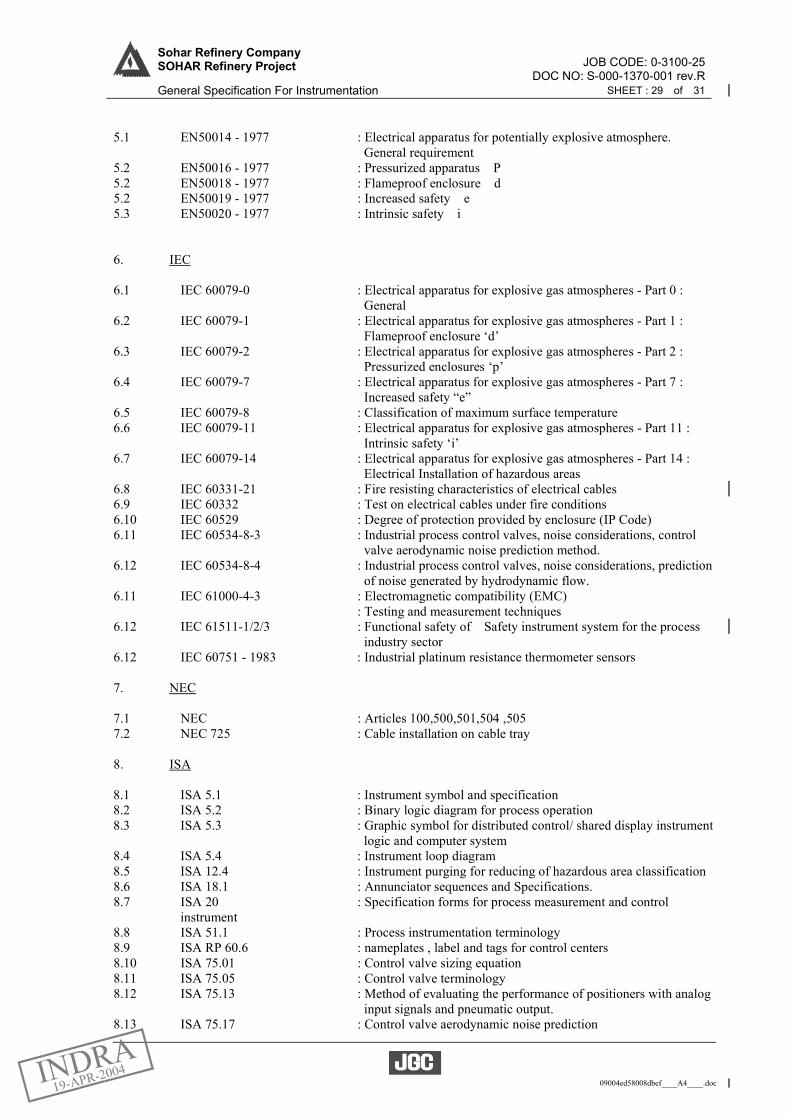
JOB CODE: 0-3100-25Sohar Refinery Company SOHAR Refinery Project
DOC NO: S-000-1370-001 rev.R General Specification For Instrumentation SHEET : 29 of 31
09004ed58008dbef____A4____.doc
5.1 EN50014 - 1977 : Electrical apparatus for potentially explosive atmosphere. General requirement 5.2 EN50016 - 1977 : Pressurized apparatus P 5.2 EN50018 - 1977 : Flameproof enclosure d 5.2 EN50019 - 1977 : Increased safety e 5.3 EN50020 - 1977 : Intrinsic safety i 6. IEC 6.1 IEC 60079-0 : Electrical apparatus for explosive gas atmospheres - Part 0 : General 6.2 IEC 60079-1 : Electrical apparatus for explosive gas atmospheres - Part 1 : Flameproof enclosure ‘d’ 6.3 IEC 60079-2 : Electrical apparatus for explosive gas atmospheres - Part 2 : Pressurized enclosures ‘p’ 6.4 IEC 60079-7 : Electrical apparatus for explosive gas atmospheres - Part 7 : Increased safety “e” 6.5 IEC 60079-8 : Classification of maximum surface temperature 6.6 IEC 60079-11 : Electrical apparatus for explosive gas atmospheres - Part 11 : Intrinsic safety ‘i’ 6.7 IEC 60079-14 : Electrical apparatus for explosive gas atmospheres - Part 14 : Electrical Installation of hazardous areas 6.8 IEC 60331-21 : Fire resisting characteristics of electrical cables 6.9 IEC 60332 : Test on electrical cables under fire conditions 6.10 IEC 60529 : Degree of protection provided by enclosure (IP Code) 6.11 IEC 60534-8-3 : Industrial process control valves, noise considerations, control valve aerodynamic noise prediction method. 6.12 IEC 60534-8-4 : Industrial process control valves, noise considerations, prediction of noise generated by hydrodynamic flow. 6.11 IEC 61000-4-3 : Electromagnetic compatibility (EMC) : Testing and measurement techniques 6.12 IEC 61511-1/2/3 : Functional safety of Safety instrument system for the process industry sector 6.12 IEC 60751 - 1983 : Industrial platinum resistance thermometer sensors 7. NEC 7.1 NEC : Articles 100,500,501,504 ,505 7.2 NEC 725 : Cable installation on cable tray 8. ISA 8.1 ISA 5.1 : Instrument symbol and specification 8.2 ISA 5.2 : Binary logic diagram for process operation 8.3 ISA 5.3 : Graphic symbol for distributed control/ shared display instrument logic and computer system 8.4 ISA 5.4 : Instrument loop diagram 8.5 ISA 12.4 : Instrument purging for reducing of hazardous area classification 8.6 ISA 18.1 : Annunciator sequences and Specifications. 8.7 ISA 20 : Specification forms for process measurement and control
instrument 8.8 ISA 51.1 : Process instrumentation terminology 8.9 ISA RP 60.6 : nameplates , label and tags for control centers 8.10 ISA 75.01 : Control valve sizing equation 8.11 ISA 75.05 : Control valve terminology 8.12 ISA 75.13 : Method of evaluating the performance of positioners with analog input signals and pneumatic output. 8.13 ISA 75.17 : Control valve aerodynamic noise prediction

JOB CODE: 0-3100-25Sohar Refinery Company SOHAR Refinery Project
DOC NO: S-000-1370-001 rev.R General Specification For Instrumentation SHEET : 30 of 31
09004ed58008dbef____A4____.doc
8.14 ISA 75.25 : Control valve dynamic testing 9. ISO 9.1 ISO 5167-2003 : Measurement of fluid flow by means of pressure differential devices 9.2 ISO 5168 : Measurement of fluid flow –Evaluation of Uncertainties 9.3 ISO 9000-1 : Quality management and quality assurance 10. JIS 10.1 C0903-1983 : Electrical apparatus for explosive atmospheres in general industry 11. NEMA 11.1 NEMA-ICS-6 : Enclosure for industrial control and system 12. TIIS 12.1 RIIS-TR-85-1 : Recommended practice for explosion-protected electrical installation in general industries 13. EEMUA 13.1 EEMUA 138 : Design and installation of on-line analyzer systems 13.2 EEMUA 133 : Armoured cable protected against solvent penetrations and corrosive attack 14. CCITT Recommendation G651 and G652/G703 for fiber optic 15. NFPA Applicable code and standard shall refer to S-000-13B0-001, General Specification for Fireproofing. 16. NACE-MR0175-2002 Sulfide stress cracking resistance metallic materials for oilfield equipment
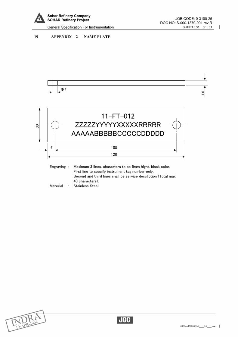
JOB CODE: 0-3100-25Sohar Refinery Company SOHAR Refinery Project
DOC NO: S-000-1370-001 rev.R General Specification For Instrumentation SHEET : 31 of 31
09004ed58008dbef____A4____.doc
19 APPENDIX – 2 NAME PLATE
09004ed580085c74____A4____.doc
JOB No. JGC DOC. No. REV.
0-3100-25 S-000-1373-201 R
DATE 12 Nov 2003 SHEET 1 OF 11
PREP’D J. Kim/ F. Edono
CHK’D S. Watanabe
APP’D H. Furuta
GENERAL SPECIFICATION
FOR
FLOW INSTRUMENTS
SOHAR REFINERY COMPANY L. L. C.
SOHAR REFINERY PROJECT
SOHAR, SULTANATE OF OMAN
Reference ITT Doc. No. Rev
N/A
REV. DATE PAGE DESCRIPTION PREP’D CHK’D APP’D
0 12-Nov-03 All For Approval J.K/ F.E S.W H.F
R 22-Mar-04 All For Construction (as per JY-OY-M-20281) T.K / F.E S.W H.F
PROJECT SPECIFICATION
Sohar Refinery Company SOHAR Refinery Project
FOR CONSTRUCTION

JOB CODE: 0-3100-25Sohar Refinery Company SOHAR Refinery Project
DOC NO: S-000-1373-201 rev.R General Specification for Flow Instruments SHEET : 2 of 11
09004ed580085c74____A4____.doc
CONTENTS
1 GENERAL ..................................................................................................................................................... 3 1.1 Scope ....................................................................................................................................................... 3 1.2 References ............................................................................................................................................... 3 1.3 Environmental Conditions ....................................................................................................................... 3 1.4 Unit of Measurement ............................................................................................................................... 3 1.5 Electrical Requirement ............................................................................................................................ 4
1.5.1 Electrical hazardous classification................................................................................................... 4 1.5.2 Enclosure ......................................................................................................................................... 4 1.5.3 Electrical connection ....................................................................................................................... 4 1.5.4 Signal transmission.......................................................................................................................... 4
1.6 Flange and Flange Face Finish ................................................................................................................ 5 1.7 Material ................................................................................................................................................... 5
2 TYPE SELECTION AND CALCULATIONS............................................................................................ 5 2.1 Type Selection ......................................................................................................................................... 5 2.2 Calculations ............................................................................................................................................. 5
3 STANDARD FLOW MEASUREMENT EQUIPMENT ........................................................................... 5 3.1 Orifice Plates ........................................................................................................................................... 6 3.2 Venturi tubes ........................................................................................................................................... 7
4 DESIGN CRITERIA FOR EACH TYPE OF INSTRUMENTS............................................................... 7 4.1 Averaging Pitot Element ......................................................................................................................... 7 4.2 Variable Area Flowmeter ........................................................................................................................ 8
4.2.1 Armored type................................................................................................................................... 8 4.2.2 Glass Tube Type.............................................................................................................................. 8
4.3 Turbine Type flowmeters ........................................................................................................................ 8 4.4 Vortex flowmeters ................................................................................................................................... 9 4.5 Ultrasonic Flowmeters............................................................................................................................. 9 4.6 Positive Displacement Flowmeters (PD meters) ................................................................................... 10 4.7 Magnetic Flowmeters ............................................................................................................................ 10 4.8 Coriolis Flowmeters .............................................................................................................................. 11 4.9 Thermal Mass Flowmeters .................................................................................................................... 11

JOB CODE: 0-3100-25Sohar Refinery Company SOHAR Refinery Project
DOC NO: S-000-1373-201 rev.R General Specification for Flow Instruments SHEET : 3 of 11
09004ed580085c74____A4____.doc
1 GENERAL
1.1 Scope
This specification defines the minimum requirements for design, manufacture and features of the flow
instruments for Sohar Refinery Project, Oman.
1.2 References
The latest edition of the following standards as of 19 May 2003 shall be referenced, unless otherwise
specified.
(1) International Organization for Standardization ISO 5167-2003: Measurement of Fluid Flow by means of Pressure Differential Devices
(2) American Society of Mechanical Engineers
(a) ASME MFC-3M: Measurement of Fluid Flow in pipes using Orifice, Flow Nozzle, and Venturi.
(b) ASME MFC-14M: Measurement of Fluid Flow Using Small Bore Precision Orifice Meters.
(c) ANSI/ASME B16.36: Orifice flanges (3) American Petroleum Institute
API RP-551-1993: Process measurement instrumentation, Section-2; Flow (4) International Electrotechnical Commission
(a) IEC 60079-0: Electrical apparatus for explosive gas atmospheres, Part-0; General (b) IEC 60079-1: Electrical apparatus for explosive gas atmospheres, Part-1; Construction and test of flameproof enclosure of electrical apparatus (c) IEC 60079-11: Electrical apparatus for explosive gas atmospheres, Part-11; Intrinsic safety ‘i’ (d) IEC 60079-14: Electrical Installation of hazardous areas (e) IEC 60529: Degree of protection provided by enclosure
(5) National Association of Corrosion Engineers NACE – MR0175-2002: Sulfide stress corrosion cracking resistance metallic materials for oil field equipment.
(6) Flow Measurement Engineering Handbook, by Richard Miller, 3rd Edition
1.3 Environmental Conditions All valves and instruments shall be suitable for installation in the climatic conditions specified below and shall be tropicalized as per the manufacturer standard procedure. All parts subject to dust, moisture, insect, corrosion, etc. shall be treated with a suitable coating to inhibit such attack in a salt laden, marine atmosphere. (1) Ambient design temperature max./min.: 47.5 (dry bulb temp.)/ 5 (Min. record
temperature is 3.5 ) shall be used for design. It shall be considered that the surface temperature does exceed the equipment design temperature in particular when exposed to direct sunlight.
(2) Relative humidity: max. /min. : 100%/6% (3) Location : Sea Coast
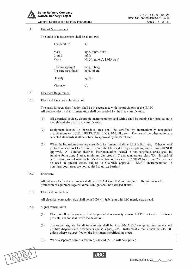
JOB CODE: 0-3100-25Sohar Refinery Company SOHAR Refinery Project
DOC NO: S-000-1373-201 rev.R General Specification for Flow Instruments SHEET : 4 of 11
09004ed580085c74____A4____.doc
1.4 Unit of Measurement The units of measurement shall be as follows:
Temperature Mass kg/h, ton/h, ton/d Liquid m3/h Vapor Nm3/h (at 0 , 1.013 bara) Pressure (gauge) barg, mbarg Pressure (absolute) bara, mbara Density kg/m3 Viscosity Cp
1.5 Electrical Requirement
1.5.1 Electrical hazardous classification
The basis for area classification shall be in accordance with the provisions of the IP/IEC. All outdoor electrical instrumentation shall be certified for the area classification. (1) All electrical devices, electronic instrumentation and wiring shall be suitable for installation in
the relevant electrical area classification. (2) Equipment located in hazardous area shall be certified by internationally recognized
organizations to, LCIE, INERIS, TIIS, EECS, FM, UL, etc. The use of the other nationally accepted standards shall be subject to approval by the Purchaser.
(3) When the hazardous areas are classified, instruments shall be EExi or Exi type. Other type of
protection, such as EEx”d” and EEx”n”, shall be used for by exceptions, and require OWNER approval. All outdoor electrical instrumentation located in non-hazardous areas shall be suitable for a zone 2 area, minimum gas group IIC and temperature class T3. Instead of certification, use of manufacturer's declaration on basis of IEC 60079.14 in zone 2 areas may be used in special cases, subject to OWNER approval. EEx”i” instrumentation in non-hazardous areas are not required to utilize barriers
1.5.2 Enclosure
All outdoor electrical instruments shall be NEMA 4X or IP 55 as minimum. Requirements for protection of equipment against direct sunlight shall be assessed at site.
1.5.3 Electrical connection All electrical connection size shall be of M20 x 1.5(female) with ISO metric size thread.
1.5.4 Signal transmission (1) Electronic flow instruments shall be provided as smart type using HART protocol. If it is not
possible, vendor shall write the deviation. (2) The output signals for all transmitters shall be 4 to 20mA DC except turbine meters and
positive displacement flowmeters (pulse signal), etc. Instrument circuits shall be 24V DC unless otherwise specified on the instrument specification sheets.
(3) When a separate power is required, 240VAC 50Hz will be supplied.
JOB CODE: 0-3100-25Sohar Refinery Company SOHAR Refinery Project
DOC NO: S-000-1373-201 rev.R General Specification for Flow Instruments SHEET : 5 of 11
09004ed580085c74____A4____.doc
1.6 Flange and Flange Face Finish All flanges shall conform to ANSI/ASME B16.36. Face finish shall be in accordance with ASME B16.5 or B16.47 as follows: Raised Face and Flat Face The gasket contact surface shall be serrated, either a concentric or continuous spiral in accordance with ASME B16.5 Para. 6.4.4.3 or B16.47 Para. 6.1.4.2. The resultant face shall be in a roughness between Ra 3.2 and Ra 6.3µm (125µin. to 250 µin.)
1.7 Material The body material of the in-line instrument shall be design in accordance with specification for piping material S-000-1360-003, element material shall be 316 stainless steel as minimum, unless otherwise specified in the instrument specification sheets.
1.8 Hart Host System Vendor shall state the compatibility of hart communication with Yokogawa PRM and other equivalent systems.
1.9 Marking The body of flow meters shall be suitably marked with the direction of flow.
2 TYPE SELECTION AND CALCULATIONS
2.1 Type Selection (1) Flow instrument types shall be properly selected in accordance with the given process data and
design criteria for flow instruments in this general specification. When any discrepancies on the type selection are found or when a suitable type cannot be found, Vendor’s recommendations shall be informed to Purchaser, the type shall be verified and determined by Purchaser.
(2) Flowmeters shall be selected on the basis of line size, fluid being metered, (its’ state), pressure
loss in the meter, meter range, accuracy, and installation requirements. (3) Vendor shall state the straight length requirements, if necessary.
2.2 Calculations (1) The vendor shall furnish detail calculations for each orifice plates and venturi tubes in
accordance with ISO 5167 based on the information provided on the instrument specification sheets.
(2) The equations from ISO 5167 are used to determine the orifice size or differential range. For
those items that fall outside of ISO 5167, the equations from ASME MFC-14M or the Flow Measurement Handbook (by Richard Miller) may be used.
(3) Primary element, (orifice plate or Venturi), sizing calculation shall be provided for each
primary element. For other types of flow meters, Vendor specific calculation information shall be provided for review by Purchaser.
3 STANDARD FLOW MEASUREMENT EQUIPMENT
The standard flow measurement equipment shall generally be a differential head producing primary
JOB CODE: 0-3100-25Sohar Refinery Company SOHAR Refinery Project
DOC NO: S-000-1373-201 rev.R General Specification for Flow Instruments SHEET : 6 of 11
09004ed580085c74____A4____.doc
element, (Orifice plate or Venturi).
3.1 Orifice Plates
(1) Types
(a) Concentric sharp edge orifice plates shall be used for most metering applications. For orifice bore diameters less than 6.35 mm, a suitable strainer shall be installed preceding the meter.
(b) Eccentric type orifice plates shall be used for fluids containing two phases. The
eccentric type orifice plates shall have the bottom of the orifice bore approximately 0.01 times the inside pipe diameter (D) above the bottom inside wall of the pipe. Eccentric orifice plates shall be installed in horizontal meter runs only.
(c) Quadrant edge orifice plates shall generally be provided for liquid flow measurement
where low Reynolds numbers, (less than 20000), are calculated for the normal process flow rate.
(d) Prefabricated meter runs, consisting of upstream and downstream honed tubes,
metering flanges, and orifice plate (honed flow meter runs), shall be provided for small flow metering applications where the pipe size is smaller than the 2 inch minimum of the conventional square edge orifice plate/meter run. In conjunction with this type of flow metering device, a suitable strainer shall be installed preceding the meter for orifice bore diameters less than 6.35 mm.
(e) Prefabricated meter runs with integral orifice meters, (in-line type orifice assembly
integrally mounted to a differential pressure transmitter), shall be used for extremely small flow rates when specified on the instrument specification sheets. In conjunction with this type of flow metering device, a suitable strainer shall be installed preceding the meter.
(2) Fabrication
(a) The Beta ratio (d/D) shall be within the following limits:
a) 0.10 and 0.70 inclusive for pipe size 2 inches and larger b) 0.15 and 0.70 inclusive for honed flow prefabricated meter runs with flange taps c) 0.10 and 0.80 inclusive for honed flow prefabricated meter runs with Corner taps d) Vendor’s recommendation for integral orifice prefabricated meter runs
Where required, the pipe size shall be expanded in diameter to avoid d/D ratios
exceeding the upper limits.
(b) Drain or weep hole shall be provided for orifice plates that have a bore diameter of 1 inch (25 mm) and larger. The drain or weep hole will be excluded from the orifice bore calculation. The size of drain or weep hole shall be in accordance with UOP standard drawing 6-111-4, Orifice Plates.
(c) Each orifice plate shall be provided with a tab that projects beyond the flange. The
tab shall be stamped to indicate the orifice plate material, measured bore diameter, normal pipe size, flange class, and identifying tag number. The tab shall also be in line with the drain or weep hole and shall clearly indicate the direction of flow. The information on the tab shall be visible when the orifice plate is installed in the flanges.
JOB CODE: 0-3100-25Sohar Refinery Company SOHAR Refinery Project
DOC NO: S-000-1373-201 rev.R General Specification for Flow Instruments SHEET : 7 of 11
09004ed580085c74____A4____.doc
(d) The construction of orifice plate shall be in accordance with UOP standard drawing 6-111-4, orifice plates.
(3) Plate Finish and Thickness
(a) The flange face finish of orifice plate shall be referred to the above Para. 1.6 Flange Face Finish.
(b) In some cases, the thickness of the orifice plate will be greater than permitted by the
limitations for the orifice edge, in such case the downstream edge shall be counter bored or beveled at an angle of 45 degrees or less to the required thickness at the orifice edge.
(4) Orifice Bore Tolerance and Finish
The upstream edge of the orifice shall be square and sharp. For two-way flow measurements both edges shall be finished. Orifice bore tolerances dimensions shall be in accordance with ISO 5167.
(5) Beta Ratio and Meter Differential
For compressible fluids, the differential in mbar shall not exceed the absolute static pressure in bar. The beta ratios indicated on the instrument specification sheets are approximate values only, for the purpose of selecting the proper meter range and/or line size. The Vendor shall confirm this value and advise of any discrepancy between this value and his calculations.
3.2 Venturi tubes
(1) The venturi tubes shall be a “Classical” venturi tube as defined in ISO 5167 or ASME venturi
tube as defined in ASME MFC-3M unless otherwise specified in the instrument specification sheet.
(2) The Beta ratio (d/D) shall be within the limits as defined in either ISO 5167 or ASME
MFC-3M, as applicable. (3) The divergent section of the venturi shall have an included angle of 7 to 8 degree in order to
minimize the permanent pressure loss. (4) Flow conditioning equipment, such as straightening vanes, is not recommended as an alternate
for required upstream pipe lengths. (5) The pipe runs upstream and downstream of the venturi shall be in accordance with UOP
standard drawing 6-134-0, piping arrangements for venturi installations. (6) Venturi meter run smoothness, out of round, etc., shall conform to the requirements of ISO
5167. (7) The meter shall be installed with accessibility from a platform, portable stairs, or temporary
ladder for servicing without increasing impulse line length.
4 DESIGN CRITERIA FOR EACH TYPE OF INSTRUMENTS
4.1 Averaging Pitot Element (1) Averaging Pitot Elements shall be selected for clean service application in large line size
measurement.
JOB CODE: 0-3100-25Sohar Refinery Company SOHAR Refinery Project
DOC NO: S-000-1373-201 rev.R General Specification for Flow Instruments SHEET : 8 of 11
09004ed580085c74____A4____.doc
(2) Averaging Pitot Elements shall be permanently marked with the proper installation position and flow direction.
(3) The straight run for Averaging Pitot Elements shall be in accordance with Vendor’s
recommendation. (4) The opposite supports shall be installed for the element where large pipe diameters or high
flow velocity service, cause the element to deflect or vibrate.
4.2 Variable Area Flowmeter
4.2.1 Armored type (1) Variable Area Flowmeters shall have a metal tube with a pressure rating compatible with the
design process conditions. (2) Variable Area Flowmeters shall be provided with inlet and outlet float stops for the float. (3) Indicating scales shall have full-length safety glass shielding with gasketting both sides and
shall be approximately 127mm in length for extension meters used for transmitting service or for armored meters, and 254mm in length for local indicators not of the armored type.
(4) Gland assemblies shall be of “O” ring construction unless otherwise specified on the
instrument specification sheets. (5) Floats shall be self-cleaning and shall be designed for maximum immunity to viscosity
variations and dimensional stability. (6) Variable Area flowmeters shall be completely assembled with all accessories before shipping
with the orientation of connections as specified on the instrument specification sheet. (7) The accuracy shall be within 2% of full scale, (10:1 rangeability, near linear readout).
4.2.2 Glass Tube Type (1) The glass tube type shall be applied for utility service, e.g. air purge service. (2) The glass tube type shall be made from stress-relieved, precision bored, tapered glass. The tube
shall be of the rib-guided type. (3) The glass tube type variable area flowmeters shall be of the enclosed type provided with side
protection plates, front windows. The windows shall be laminated safety glass. This window shall not shatter when exposed to line pressure.
(4) Packing glands shall be provided at each end of the tube. (5) The glass tube type variable area flowmeters shall have pressure and temperature rating
conform to the specified service conditions. (6) The accuracy of glass tube type purge meter shall be within 10% of full scale.
4.3 Turbine Type Flowmeters (1) The application of turbine meters shall be considered where high accuracy is required. (2) Turbine meter shall not be damaged from over-ranging flow and from suffering hydraulic
shock. (3) The accuracy of the meter shall be 0.5% of flow and the repeatability shall be 0.1% unless

JOB CODE: 0-3100-25Sohar Refinery Company SOHAR Refinery Project
DOC NO: S-000-1373-201 rev.R General Specification for Flow Instruments SHEET : 9 of 11
09004ed580085c74____A4____.doc
noted otherwise on the instrument specification sheets. (4) Material of construction for the journal bearing and rotor shaft shall be tungsten carbide. The
materials of construction for the body and other wetted parts shall be suitable for hydrocarbon service as defined on the instrument specification sheets.
(5) The pickup coil shall be hermetically sealed or potted. The length of wiring between the
pickup coil and pulse amplifier shall be sufficient to permit the amplifier to be located as close to the meter but not on the meter.
(6) All turbine meters shall be designed for at least 130% operation of the flow range specified. (7) Strainers with the mesh size, material, and rating as specified on the instrument specification
sheets shall be installed to prevent rotor damage. (8) Straight run shall be in accordance with the manufacturer’s recommendation.
4.4 Vortex Flowmeters
Vortex flow meter shall be considered as alternative where its piping diameter is less than 6 inch. Insertion type vortex flowmeters may be used for large piping diameter. Vortex flow meter shall be used for liquid, steam and gas where the requirements include high accuracy together with a high turndown ratio. However, Vortex flow meters shall not be applied in wet steam/gas applications. Where Vortex meter is mounted in an inaccessible location, remote electronics type shall be used.
(1) Vortex meters should be an alternative selection only, in particular where a large turndown is
required. (2) Vortex meter shall not be used for slurries or high viscosity liquids. (3) The applications for high temperature service shall be applied in accordance with Vendor’s
recommendation. (4) The internal diameter of upstream pipe and flanges shall be equal to the inside diameter of
Vortex flow meter in order not to disturb the flow profile. (5) The material for body and element shall conform to the instrument specification sheets. (6) Accuracy: ± 1.0% of full scale (10: 1 rangeability, linear signal) (7) Recommended straight length:
(a) Upstream = 10 diameters (b) Downstream = 5 diameters
4.5 Ultrasonic Flowmeters
(1) Ultrasonic flowmeters shall be applied with the following conditions:
(a) Ultrasonic flow meters may be used for liquid and gas applications where there is the requirement for the flow measurement to present a minimum obstruction to the flow or for bi-directional flow measurement.
(b) No restriction in the flow stream is allowed and special applications such as flare gas
measurement.
(c) Gas conditions (components, pressure, temperature) vary.
JOB CODE: 0-3100-25Sohar Refinery Company SOHAR Refinery Project
DOC NO: S-000-1373-201 rev.R General Specification for Flow Instruments SHEET : 10 of 11
09004ed580085c74____A4____.doc
(d) Measurement is required for a large line.
(e) A big turn-down is expected, for gas service. (2) Ultrasonic flow meters shall meet the following minimum requirements:
(a) Use an Ultrasonic transmit-time technique
(b) Ultrasonic probes to be immersed to the fluid
(c) Continuously measure velocity, volumetric.
(d) Continuously determine instantaneous average molecular weight
(e) Have a minimum of three assignable 4-20 mA analog outputs to indicate velocity, volumetric flow, molecule weight, sound speed, or Mass Flow
(3) Meters shall not be installed where high noise is expected, such as downstream of cavitating or
noisy valves. Care shall be taken if the meter and control valves are installed in the same line. (4) Typical accuracy: ±1.0% of full scale (10:1 rangeability, linear signal) (5) Meter straight run shall be in accordance with the manufacturer’s recommendation.
4.6 Positive Displacement Flowmeters (PD meters)
(1) The major application of Positive Displacement Flowmeters shall be the custody transfer of
heavy products. (2) Positive displacement meter shall be primarily used where highly accuracy ±0.3% of flow rate
and wide range (10:1 or more) measurement is required and the meters shall be used on volumetric totalization rather than rate of flow.
(3) Flow limiting devices shall be considered to prevent over-ranging of positive displacement
meters. Certain types of positive displacement meters have their maximum capacity limited not only by flow, but also by the maximum allowable pressure drop across the meter. Consideration should be given to limiting the maximum pressure drop, especially when the meter is used with high pour point liquids having a high viscosity.
(4) Positive Displacement Flowmeters shall have a direct-coupled pulse generator and be provided
with signal amplifiers mounted close to the meter. (5) The meters shall not be damaged due to hydraulic shock, caused for example, by the quick
opening and closing of valves. (6) Positive Displacement Flowmeter systems shall be designed in accordance with API Std 1101. (7) Positive Displacement Flowmeters are sensitive to foreign matter and a filter/strainer should
therefore be installed upstream of the meter. The size of the mesh shall be designed according to the manufacturer’s recommendation.
(8) Positive Displacement Flowmeters shall not be used for dry gas
4.7 Magnetic Flowmeters (1) Magnetic Flowmeters shall be considered where no restriction in the flow stream is allowed
and/or for corrosive fluids and slurries application that have adequate electrical conductivity. (2) Magnetic Flowmeters are suitable for very viscous fluids and where negligible pressure drop is

JOB CODE: 0-3100-25Sohar Refinery Company SOHAR Refinery Project
DOC NO: S-000-1373-201 rev.R General Specification for Flow Instruments SHEET : 11 of 11
09004ed580085c74____A4____.doc
required. (3) The process fluid should have conductivity greater than 2 micro-mhos per centimeter, but
special units are available for fluids with conductivity as low as 0.1 micro-mhos per centimeter.
(4) Magnetic Flowmeters must run full of liquid to ensure an accurate measurement. (5) Magnetic Flowmeters can be used to measure bi-directional flow. (6) Accuracy is typically ± 0.5% of flow rate depending of number of paths (10:1 rangeability,
linear signal) (7) Recommended straight pipe length is as follow:
(a) Upstream = 5 diameters (b) Downstream = 2 diameters
4.8 Coriolis Flowmeters
(1) Coriolis Flowmeters may be considered where including liquid with limited amounts of
entrained gas and slurries, and can also be used with dry gases and superheated steam if the fluid’s density is high enough to operate the unit properly.
(2) Coriolis Flowmeters shall be applied in mass and volume measurement applications with a
mass signal and also a separate density signal output. (3) Accuracy is typically ± 0.2% of flow rate (20:1 rangeability, linear signal). (4) Meter straight run shall be in accordance with the manufacturer’s recommendation. (5) Over-ranging will not damage the meter. (6) It should be noted that Coriolis Flowmeters incur relatively high-pressure drops.
4.9 Thermal Mass Flowmeters (1) Thermal Mass Flowmeters shall be considered where other types of measurement as listed
above are unsatisfactory and used for gas or air flow measurement (2) Thermal Mass Flowmeters may be used for the measurement of air flows where high
rangeability and large capacity is required. (3) Thermal Mass Flowmeters shall be applied only where quick response time is not required. (4) Thermal Mass Flowmeters must be calibrated for specific fluid as the inferred flow rate is
related to several of the fluid’s properties. (5) Straight run shall be in accordance with the manufacturer’s recommendation.

09004ed580089167____A4____.doc
JOB No. JGC DOC. No. REV.
0-3100-25 S-000-1373-401 R
DATE 12 Nov 2003 SHEET 1 OF 8
PREP’D J. Kim/ F. Edono
CHK’D S. Watanabe
APP’D H. Furuta
GENERAL SPECIFICATION
FOR
TEMPERATURE INSTRUMENTS
SOHAR REFINERY COMPANY L. L. C.
SOHAR REFINERY PROJECT
SOHAR, SULTANATE OF OMAN
Reference ITT Doc. No. Rev
N/A
REV. DATE PAGE DESCRIPTION PREP’D CHK’D APP’D
0 12-Nov-03 All For Approval J.K / F.E S.W H.F
R 22-Mar-04 All For Construction (as per JY-OY-M-20281) T.K / F.E S.W H.F
PROJECT SPECIFICATION
Sohar Refinery Company SOHAR Refinery Project
FOR CONSTRUCTION
JOB CODE: 0-3100-25Sohar Refinery Company SOHAR Refinery Project
DOC NO: S-000-1373-401 rev.R
General Specification for Temperature Instruments SHEET : 2 of 8
09004ed580089167____A4____.doc
CONTENTS
1 GENERAL ..................................................................................................................................................... 3 1.1 Scope ....................................................................................................................................................... 3 1.2 References ............................................................................................................................................... 3 1.3 Environmental Conditions ....................................................................................................................... 3 1.4 Unit of Measurement ............................................................................................................................... 3 1.5 Flange and Flange Face Finish ................................................................................................................ 4
2 TEMPERATURE INSTRUMENTS......................................................................................................... 4 2.1 Temperature Transmitters........................................................................................................................ 4 2.2 Temperature Elements............................................................................................................................. 5 2.3 Thermometers.......................................................................................................................................... 6 2.4 Pyrometer ................................................................................................................................................ 7
3 THERMOWELL........................................................................................................................................... 7 3.1 General .................................................................................................................................................... 7 3.2 Construction ............................................................................................................................................ 7
4 ELECTRICAL REQUIREMENT ............................................................................................................... 7 4.1 Electrical hazardous classification........................................................................................................... 7 4.2 Enclosure ................................................................................................................................................. 8 4.3 Electrical connection ............................................................................................................................... 8
5 ACCESSORIES............................................................................................................................................. 8 5.1 Mounting Bracket.................................................................................................................................... 8 5.2 Local Indicator......................................................................................................................................... 8
JOB CODE: 0-3100-25Sohar Refinery Company SOHAR Refinery Project
DOC NO: S-000-1373-401 rev.R
General Specification for Temperature Instruments SHEET : 3 of 8
09004ed580089167____A4____.doc
1 GENERAL
1.1 Scope
This specification defines the minimum requirements for design, manufacture and features of the temperature instruments for Sohar Refinery Project, Oman.
1.2 References
The latest edition of the following standards as of 19 May 2003 shall be referenced, unless otherwise
specified.
(1) American Petroleum Institute API RP-551-1993: Process measurement instrumentation, Section-5 Temperature
(2) National Association of Corrosion Engineers
NACE – MR0175-2002: Sulfide stress corrosion cracking resistance metallic materials for oil field equipment.
(3) International Electrotechnical Commission
(a) IEC 60079-0: Electrical apparatus for explosive gas atmospheres, Part-0: General (b) IEC 60079-1: Electrical apparatus for explosive gas atmospheres, Part-1; Construction and test of flameproof enclosure of electrical apparatus (c) IEC 60079-11: Electrical apparatus for explosive gas atmospheres, Part-11; Intrinsic safety ‘i’ (d) IEC 60079-14: Electrical Installation of hazardous areas (e) IEC 60529: Degree of protection provided by enclosure (f) IEC 60751: Industrial platinum resistance thermometer sendors
(4) ANSI / ASME
(a) MC 96.1: Temperature Measurement Thermocouples (b) PTC 19.3 Temperature Measurement
(5) NEMA
ICS 6: Enclosure for industrial control and system
1.3 Environmental Conditions All instruments shall be suitable for installation in the climatic conditions specified below and shall be tropicalized as per the manufacturer standard procedure. All parts subject to dust, moisture, insect, corrosion, etc. shall be treated with a suitable coating to inhibit such attack in a salt laden, marine atmosphere. (1) Ambient design temperature max./min.: 47.5 (dry bulb temp.)/ 5 (Min. record temperature
is 3.5 ) shall be used for design. It shall be considered that the surface temperature does exceed the equipment design temperature in particular when exposed to direct sunlight.
(2) Relative humidity: max. /min. : 100%/6% (3) Location : Sea Coast
1.4 Unit of Measurement The units of measurement shall be as follows:
Temperature

JOB CODE: 0-3100-25Sohar Refinery Company SOHAR Refinery Project
DOC NO: S-000-1373-401 rev.R
General Specification for Temperature Instruments SHEET : 4 of 8
09004ed580089167____A4____.doc
Mass kg/h, ton/h, ton/d Liquid m3/h Vapor Nm3/h (at 0 , 1.013 bara) Pressure (gauge) barg, mbarg Pressure (absolute) bara, mbara Density kg/m3 Viscosity Cp
1.5 Flange and Flange Face Finish
All flanges shall conform to ANSI/ASME B16.36. Face finish shall be in accordance with ASME B16.5 or B16.47 as follows: Raised Face and Flat Face The gasket contact surface shall be serrated, either a concentric or continuous spiral in accordance with ASME B16.5 Para. 6.4.4.3 or B16.47 Para. 6.1.4.2. The resultant face shall be in a roughness between Ra 3.2 and Ra 6.3µm (125µin. to 250 µin.)
2 TEMPERATURE INSTRUMENTS 2.1 Temperature Transmitters
(1) General
(a) Temperature transmitters shall be designed in accordance with the general specification for transmitters S-000-1373-001.
(b) Transmitters shall be direct head mounted type, unless otherwise specified on the
instrument specification sheets. The remote type temperature transmitters should be used for high temperature service (i.e. more than 500C for the process maximum temperature), to protect electronic parts. In case multiple-elements are used and where vibration is generated, such as reciprocating compressor, remote type temperature transmitter may be used.
(c) The smart type transmitters shall be provided except for the bearing temperature and
winding temperature measurement for compressors and pumps. (2) Input
(a) Loop powered transmitters shall have the input isolated from the output. Transmitters with external power supplies shall have the input isolated from the output and power supply.
(b) In case RTD: 3-wire Pt 100 ohm at 0 C shall be used
(c) In case Thermocouples: Type E, J, K and R shall be applied depend on process
temperature.
(d) Thermocouple and RTD circuits operating high temperature alarms and high/low both temperature alarms shall have upscale element burnout. Those on low temperature alarms shall fail to down scale position.
(3) Output

JOB CODE: 0-3100-25Sohar Refinery Company SOHAR Refinery Project
DOC NO: S-000-1373-401 rev.R
General Specification for Temperature Instruments SHEET : 5 of 8
09004ed580089167____A4____.doc
(a) The transmitter output for the specified range shall generally be 4-20mA with a digital communication protocol superimposed (HART) or 4-20mA analogue only by exception. The communication protocol shall not prevent the instrument from measurement and transmitting the process temperature, except when the instrument is being configured.
(b) For a transmitter with 4-20mA outputs, self-diagnostic shall be able to detect both a
thermocouple/RTD sensor failure and transmitter electronics failure. The transmitters shall be user selectable to drive the output upscale above 21mA or downscale below 3.6mA on failure detection. Upscale drive on failure detection shall be selected unless otherwise specified.
Saturation current limits shall be, NAMUR compliant, in accordance with the following: Fail low: I < 3.6 mA Fail high: 21.0 mA < I < 23.0 mA Low saturation: I = 3.8 mA High saturation: I = 20.5 mA
(4) Performance
(a) Digital, Micro-processor based, transmitters
Digital, accuracy<0.28C for RTDs and <0.55C for thermocouples. Digital to analog conversion accuracy for milliamp outputs shall be less than
0.05% of calibrated span. Combined digital accuracy for a 28C change in ambient temperature <0.55C
RTDs and <1.1C for thermocouples. Temperature output shall be linear.
(b) Electrical analog transmitter accuracy shall be 0.5%, or better, of calibrated span and
includes the effects of repeatability, hysteresis, and linearity. (5) Range
The scale ranges shall be selected such that the normal temperature shall be indicated within 30% - 70% of the range. The range of any temperature-measuring instrument shall be the manufacture’s narrowest standard span appropriate to the application.
(6) HART host system
Vendor shall state the compatibility of hart communication with Yokogawa PRM and other equivalent systems.
2.2 Temperature Elements
(1) Resistance Temperature Detector (RTD)
(a) Pt 100 ohm RTD elements shall be used where the temperature is 450C and below.
(b) RTD element with 3-wires shall be designed in accordance with IEC 60751.
(c) The bearing and winding temperature signals with RTD shall be directly connected to its related temperature monitors.

JOB CODE: 0-3100-25Sohar Refinery Company SOHAR Refinery Project
DOC NO: S-000-1373-401 rev.R
General Specification for Temperature Instruments SHEET : 6 of 8
09004ed580089167____A4____.doc
(d) Temperature elements shall be 6.4 mm OD sheath and 316SS material as minimum, unless otherwise specified on the instrument specification sheets.
(2) Thermocouple Elements
(a) Thermocouple initial calibration tolerances shall not be greater than the standard tolerances listed in ANSI MC 96.1. Type –K thermocouple shall be used where the temperature is above 450C. Tube skin point temperature shall be type-K.
(b) For temperature above 1100C, or H2 service above 750C, noble metal thermocouples
shall be used.
(c) Remote type thermocouple head terminals shall be marked with positive and negative symbols. The head shall be protected to IP55 or NEMA 4X as minimum.
(d) When elements, terminal heads, connecting piping, thermocouple wells and protecting
tubes are supplied by one vendor, the components shall be assembled into complete units. Upon assembly of the components, the element shall firmly contact the bottom of the well (spring loaded type).
(e) Temperature elements shall be 6.4 mm OD sheath and 316SS material as minimum,
unless otherwise specified on the instrument specification sheets.
2.3 Thermometers (1) General
(a) Bi-metallic dial thermometers shall be used for local indication of temperature up to 500 deg C.
(b) Dial thermometers shall be preferred with adjustable angle type for obtaining good
reading position. When a thermometer is mounted in a vertical thermowell, the gauge should have a vertical scale. 100 mm dials shall be used.
(c) Liquid Filled type thermometer shall be used where vibration is generated such as
reciprocating compressor. (2) Meter Range
(a) In principle, the meter range shall be selected in such a way that the normal operating temperature is between 30 and 70% of the meter range.
(b) Meter range shall be selected with the following scale ranges
Scale range (C)
-50 50 -20 60 0 100 0 160 0 250 0 400 0 500
(3) Material
Sheath material shall be stainless steel as minimum, and case material shall be manufacturer’s standard, suitable for the environment of installation.
JOB CODE: 0-3100-25Sohar Refinery Company SOHAR Refinery Project
DOC NO: S-000-1373-401 rev.R
General Specification for Temperature Instruments SHEET : 7 of 8
09004ed580089167____A4____.doc
2.4 Pyrometer (1) General
(a) Pyrometer (Infrared), is suitable where non-contact measurement is required due to high temperature.
(b) On the selection of the fixes mount type pyrometer, care shall be taken on the
following: Environnent, i.e. ambient temperature Target size and distance
(c) For installation in high temperature or dusty ambient, cooling water jacket or air purge
shell are required.
3 THERMOWELL
3.1 General (1) The Karman vortex effect shall be calculated, where it is required, and thermowell shall have
enough strength to withstand it. Standard flanged thermowell size of 1-1/2-inch shall be used. 2-inch design may be used for high fluid velocity if required.
(2) Thermowells shall be designed for vibration and stress according to ASME/ANSI Performance
Test Code (PTC) 19.3. Where the result of the calculation is not satisfied, the thermowell design shall be modified with reducing the well length, furthermore increasing of the diameter.
(3) All thermowell material shall be 316SS as minimum, unless otherwise specified on the
instrument specification sheets. (4) Thermowell length shall be standardized per following table. Alternative (ALT) insertion
well length may be applied to solve the Karman vortex effect problem.
Installation on STD insertion well length (U) ALT insertion well length (U)Up to 6 inch pipe 250 mm 225 mm
8 inch pipe and large 300 mm 250 mm, 275 mm Tank and Vessel 450 mm
3.2 Construction
(1) Thermowells for thermocouple and RTD shall be designed in accordance with UOP standard
drawing 6-105-4, Thermowells, except for flange size. (2) Thermowells for thermometer and temperature switch shall be designed in accordance with
UOP standard drawing 6-106-3, Thermometer assemblies, except for flange size. (3) A union and nipples shall be provided between thermowell and terminal head/transmitter.
4 ELECTRICAL REQUIREMENT
4.1 Electrical hazardous classification The basis for area classification shall be in accordance with the provisions of the IP/IEC. All outdoor electrical instrumentation shall be certified for the area classification.
JOB CODE: 0-3100-25Sohar Refinery Company SOHAR Refinery Project
DOC NO: S-000-1373-401 rev.R
General Specification for Temperature Instruments SHEET : 8 of 8
09004ed580089167____A4____.doc
(1) All electrical devices, electronic instrumentation and wiring shall be suitable for installation in the relevant electrical area classification.
(2) Equipment located in hazardous area shall be certified by internationally recognized
organizations to, LCIE, INERIS, TIIS, EECS, FM, UL, etc. The use of the other nationally accepted standards shall be subject to approval by the Purchaser.
(3) When the hazardous areas are classified, instruments shall be EExi or Exi type. Other type of
protection, such as EEx”d” and EEx”n”, shall be used for by exceptions, and require OWNER approval. All outdoor electrical instrumentation located in non-hazardous areas shall be suitable for a zone 2 area, minimum gas group IIC and temperature class T3. Instead of certification, use of manufacturer's declaration on basis of IEC 60079.14 in zone 2 areas may be used in special cases, subject to OWNER approval. EEx”i” instrumentation in non-hazardous areas are not required to utilize barriers
4.2 Enclosure
All outdoor electrical instruments shall be NEMA 4X or IP 55 as minimum.
4.3 Electrical connection All electrical connection size shall be of M20 x 1.5 (female) with ISO metric size thread.
5 ACCESSORIES
5.1 Mounting Bracket Remote type temperature transmitters or remote indicators shall be furnished with a universal mounting bracket for 2” pipe stanchion
5.2 Local Indicator All direct head mounted type transmitters shall be provided a digital type integral indicator, unless otherwise specified on the instrument specification sheets.

09004ed580084b77____A4____.doc
JOB No. JGC DOC. No. REV.
0-3100-25 S-000-1373-001 R
DATE 12 Nov 2003 SHEET 1 OF 8
PREP’D J. Kim/ F. Edono
CHK’D S. Watanabe
APP’D H. Furuta
GENERAL SPECIFICATION
FOR
TRANSMITTERS
SOHAR REFINERY COMPANY L. L. C.
SOHAR REFINERY PROJECT
SOHAR, SULTANATE OF OMAN
Reference ITT Doc. No. Rev
N/A
REV. DATE PAGE DESCRIPTION PREP’D CHK’D APP’D
0 12-Nov-03 All For Approval J.K / F.E S.W H.F
R 22-Mar-03 All For Construction (as per JY-OY-M-20281) T.K / F.E S.W H.F
PROJECT SPECIFICATION
Sohar Refinery Company SOHAR Refinery Project
FOR CONTRUCTION

JOB CODE: 0-3100-25Sohar Refinery Company SOHAR Refinery Project
DOC NO: S-000-1373-001 rev.R General Specification for Transmitters SHEET : 2 of 8
09004ed580084b77____A4____.doc
CONTENTS
1 GENERAL ......................................................................................................................................................3 1.1 Scope ........................................................................................................................................................3 1.2 References ................................................................................................................................................3 1.3 Environmental Conditions ........................................................................................................................3 1.4 Unit of Measurement ................................................................................................................................3 1.5 Flange and Flange Face Finish .................................................................................................................4 1.6 General Design Requirement....................................................................................................................4
2 PRESSURE & DIFFRENTIAL PRESSURE TRANSMITTER requirements.........................................4 2.1 Differential Pressure Type Flow Transmitter ...........................................................................................4 2.2 Differential Pressure Type Level Transmitter ..........................................................................................5 2.3 Pressure Transmitter .................................................................................................................................5 2.4 Differential Pressure Transmitter .............................................................................................................5 2.5 Performance..............................................................................................................................................5
3 ELECTRICAL REQUIREMENT ................................................................................................................6 3.1 Electrical hazardous classification............................................................................................................6 3.2 Signal transmission...................................................................................................................................7 3.3 Enclosure ..................................................................................................................................................7 3.4 Electrical connection ................................................................................................................................7
4 Accessories ......................................................................................................................................................7 4.1 Mounting Bracket.....................................................................................................................................7 4.2 Local Indicator..........................................................................................................................................7 4.3 Valve Manifold.........................................................................................................................................7
JOB CODE: 0-3100-25Sohar Refinery Company SOHAR Refinery Project
DOC NO: S-000-1373-001 rev.R General Specification for Transmitters SHEET : 3 of 8
09004ed580084b77____A4____.doc
1 GENERAL
1.1 Scope
This specification defines the minimum requirements for design, manufacturer and features of the
electronic transmitters for Sohar Refinery Project.
1.2 References
The latest edition of the following standards as of 19 May 2003 shall be referenced, unless otherwise
specified.
(1) American Petroleum Institute API RP 551-1993: Process Measurement Instrumentation;
Section 2-FLOW Section 3-LEVEL Section 4-PRESSURE
(2) National Association of Corrosion Engineers NACE MR0175-2002: Sulfide Stress Cracking Resistant Metallic Materials for Oilfield Equipment
(3) International Electrotechnical Commission
(a) IEC 60079-0: Electrical apparatus for explosive gas atmospheres, part-0; General (b) IEC 60079-1: Electrical apparatus for explosive gas atmospheres, Part-1; Flameproof enclosure ‘d’ (c) IEC 60079-11: Electrical apparatus for explosive gas atmospheres, Part-11; Intrinsic safety ‘i’ (d) IEC 60079-14: Electrical Installation of hazardous areas (e) IEC 60529: Degree of protection provided by enclosure
1.3 Environmental Conditions
All instruments shall be suitable for installation in the climatic conditions specified below and shall be tropicalized as per the manufacturer standard procedure. All parts subject to dust, moisture, insect, corrosion, etc. shall be treated with a suitable coating to inhibit such attack in a salt laden, marine atmosphere. (1) Ambient design temperature max./min.: 47.5 (dry bulb temp.)/ 5 (Min. record
temperature is 3.5 ) shall be used for design. It shall be considered that the surface temperature does exceed the equipment design temperature in particular when exposed to direct sunlight.
(2) Relative humidity: max. / min. : 100% / 6% (3) Location : Sea Coast
1.4 Unit of Measurement
The units of measurement shall be as follows:
Temperature Mass kg/h, ton/h, ton/d Liquid m3/h
JOB CODE: 0-3100-25Sohar Refinery Company SOHAR Refinery Project
DOC NO: S-000-1373-001 rev.R General Specification for Transmitters SHEET : 4 of 8
09004ed580084b77____A4____.doc
Vapor Nm3/h (at 0 , 1.013 bara) Pressure (gauge) barg, mbarg Pressure (absolute) bara, mbara Density kg/m3 Viscosity Cp
1.5 Flange and Flange Face Finish
All flanges shall conform to ANSI/ASME B16.36. Face finish shall be in accordance with ASME B16.5 or B16.47 as follows: Raised Face and Flat Face The gasket contract surface shall be serrated in either a concentric or continuous spiral in accordance with ASME B16.5 Para. 6.4.4.3 or B16.47 Para. 6.1.4.2. The resultant of face shall be in a roughness between Ra 3.2 and Ra 6.3µm (125µin. to 250 µin.)
1.6 General Design Requirement
(1) The material of the transmitter body shall be Cadmium plated carbon steel or 316 SS,
diaphragm material shall be 316 stainless steel as minimum, unless otherwise specified in the instrument specification sheets.
(2) For absolute, gauge pressure transmitters and differential pressure transmitters, the transmitter
body shall have a static pressure rating of 105 barg or 150% of the sensor upper range limit (URL) at the operating temperature, whichever is greater.
(3) For pressure transmitters and differential pressure transmitters, any resultant zero shifts shall be
limited to less than 1 % of the calibrated span of the transmitter. (4) Transmitters shall be with 1/2" NPT screwed process connections. (5) All transmitters shall have adjustable zero and span. (6) All instruments shall be factory calibrated for the specified range.
2 PRESSURE & DIFFRENTIAL PRESSURE TRANSMITTER REQUIREMENTS
2.1 Differential Pressure Type Flow Transmitter (1) Basically square root flow signals from the field shall be linearized in the flow transmitter and
not in DCS, except where the square root signal is required in calculations or in control (e.g. antisurge control).
(2) Unless otherwise specified in licenser’s specification, based on linear scale, the flowmeters
shall be ranged for a reading at:
(a) Maximum flow between 90% and 98% of the scale.
(b) Normal flow between 70% and 75% of the scale.
(c) Minimum flow shall not be below 30% of the scale for all applications other than those referred to above.
JOB CODE: 0-3100-25Sohar Refinery Company SOHAR Refinery Project
DOC NO: S-000-1373-001 rev.R General Specification for Transmitters SHEET : 5 of 8
09004ed580084b77____A4____.doc
2.2 Differential Pressure Type Level Transmitter (1) Differential Pressure Level Instruments shall be generally used for level measurement, except
for interface level measurement. (2) Where material is liable to separate, solidify or deposit in impulse lines, the lines should be
purged or trace heated as appropriate. Alternatively, direct mounting diaphragms may be used. Adequate mechanical protection for capillaries shall be provided. The effect of blockages or capillary failure on the integrity of process control and safety systems shall be assessed.
(3) The Contractor will specify the appropriate seal liquid in the impulse line where it is required,
which requirement will be specified on the individual instrument specification sheets. (4) A dry or gas-purged reference leg should be used for applications where it is impractical to
maintain a filled reference leg, (e.g. in vacuum systems). (5) The instrument range, suppression or elevation depends on the physical dimensions of the
installation and densities of the various fluids. (6) The required instrument range and elevation or suppression shall be specified in mbar.
2.3 Pressure Transmitter (1) In services that are corrosive to available transmitter internals, where plugging may occur, or
high viscosity fluids are encountered, diaphragm seals compatible with the process fluid shall be used to isolate the transmitter internals from the process fluid.
(2) For absolute and gauge pressure transmitters, measuring elements shall be capable of
withstanding pressure up to that of the static pressure rating without damage to the element. (3) Pressure instruments shall have over-range (for pressure) and under-range (for vacuum)
protection to prevent mechanical damage or shift in calibration. Where necessary, the over-range protection shall cover and exceed the relevant relieving pressure of safety relief valve.
(4) Output signals from the field shall be linearized in the pressure transmitter.
2.4 Differential Pressure Transmitter (1) In services that are corrosive to available transmitter internals, where plugging may occur, or
high viscosity fluids are encountered, diaphragm seals compatible with the process fluid shall be used to isolate the transmitter internals from the process fluid.
(2) Differential pressure transmitters shall be installed on the ground level or on the platform with
2 inch pipe stanchion and impulse line length to be minimized to avoid a measurement error due to any specified gravity differences in the high and low impulse lines.
2.5 Performance
(1) Response time and Update Rate
(a) For transmitter used in process control loops, response time and update rate shall be used in determining transmitter performance and both criteria shall be considered in the selection of the equipment. Response time is defined as the time it takes for the transmitter output to reach 63.2% of the actual step change in pressure. The response time includes any dead time associated with the initial step change in input signal and the transmitter output actually changing. Update rate is defined as the time interval between updates of the transmitted process measurement value.

JOB CODE: 0-3100-25Sohar Refinery Company SOHAR Refinery Project
DOC NO: S-000-1373-001 rev.R General Specification for Transmitters SHEET : 6 of 8
09004ed580084b77____A4____.doc
(b) As a minimum, pressure and differential pressure digital transmitters used in process control loops shall meet the following requirements.
a) Transmitter with an upper range limit of 76 mbar or less shall have a response time
of 600 milliseconds or less. Other transmitters shall have a response time of 500 milliseconds or less.
b) Transmitters shall have an update rate at least as fast as the table below. The
table is based upon a transmitter update rate at least twice as fast as the proportional, integral, derivative (PID) controller algorithm execution rate.
Control Type Output Signal update rate Flow ( P), Pressure, Differential Pressure Level ( P)
125 milliseconds 500 milliseconds
Faster update rate/response time transmitters may be required for certain applications such as compressor antisurge control systems. Slow update rate/response time transmitters may degrade control performance.
(2) Process Measurement Communication Protocol
The communication protocol shall not prevent the instrument from measuring and transmitting the process pressure or differential pressure, except when the instrument is being configured.
(3) Failure Mode
The transmitter electronics shall be capable of monitoring its performance during normal operation. The diagnostics shall be able to detect both an input sensor failure and transmitter electronics failure. The sensor or electronics failure shall be transmitted to the host system (e.g. DCS, PLC) using a low milliamp signal (as below) or by using a HART signal, depending on the capabilities of the host system.
The transmitter shall be provided with burn-out protection. Alarm (burn-out) and saturation current limits shall be, NAMUR compliant, in accordance with the following:
Fail low: I < 3.6 mA Fail high: 21.0 mA < I < 23.0 mA Low saturation: I = 3.8 mA High saturation: I = 20.5 mA
(4) Electronic Damping
The transmitter shall be capable of setting the electronic damping of the output to zero. Damping values shall be set to zero, unless specified otherwise.
(5) Vendor Factory Calibration
The instrument calibration shall be completed by the vendor prior to shipment of the instrument. Only calibration via a smart communicator is not acceptable for vendor’s factory calibration.
(6) HART host system Vendor shall state the compatibility of hart communication with Yokogawa PRM and other equivalent systems.
3 ELECTRICAL REQUIREMENT
3.1 Electrical hazardous classification
JOB CODE: 0-3100-25Sohar Refinery Company SOHAR Refinery Project
DOC NO: S-000-1373-001 rev.R General Specification for Transmitters SHEET : 7 of 8
09004ed580084b77____A4____.doc
The basis for area classification shall be in accordance with the provisions of the IP/IEC. All outdoor electrical instrumentation shall be certified for the area classification. (1) All electrical devices, electronic instrumentation and wiring shall be suitable for installation in
the relevant electrical area classification. (2) Equipment located in hazardous area shall be certified by internationally recognized
organizations to, LCIE, INERIS, TIIS, EECS, FM, UL, etc. The use of the other nationally accepted standards shall be subject to approval by the Purchaser.
(3) When the hazardous areas are classified, instruments shall be EExi or Exi type. Other type of
protection, such as EEx”d” and EEx”n”, shall be used for by exceptions, and require OWNER approval. All outdoor electrical instrumentation located in non-hazardous areas shall be suitable for a zone 2 area, minimum gas group IIC and temperature class T3. Instead of certification, use of manufacturer's declaration on basis of IEC 60079.14 in zone 2 areas may be used in special cases, subject to OWNER approval. EEx”i” instrumentation in non-hazardous areas are not required to utilize barriers
3.2 Signal transmission
All electronic transmitters shall be smart type and 4 to 20mA with digital communication protocol superimposed (HART) except for service where the high-speed response is required, non-smart type transmitter may be used for compressor anti-surge control.
3.3 Enclosure All outdoor electrical instruments shall be NEMA 4X or IP 55 as minimum. Requirements for protection of equipment against direct sunlight shall be assessed at site.
3.4 Electrical connection All electrical connection size shall be of M20 x 1.5(female) with ISO metric size thread.
4 ACCESSORIES 4.1 Mounting Bracket
All transmitters and remote indicators shall be furnished with a universal mounting bracket for 2" pipe stanchion.
4.2 Local Indicator All instruments shall be provided a digital type integral indicator unless otherwise specified on the instrument specification sheets.
4.3 Valve Manifold The manifold valves shall be supplied by JGC for the following based, unless otherwise specified on the instrument specification sheets. For high-pressure service (900# or 1500#) and pressure lead piping application, piping valves shall be used. Instrument type Manifold type Differential pressure flow transmitters (FT) 5 valves manifold Differential pressure transmitters (PDT) 5 valves manifold (note 1) Differential pressure transmitters (PDT) 4 valves manifold (note 2) Differential pressure level transmitters (LT) 4 valves manifold (note 3) Pressure transmitters (PT) 2 valves manifold Note 1. For low differential pressure service.

JOB CODE: 0-3100-25Sohar Refinery Company SOHAR Refinery Project
DOC NO: S-000-1373-001 rev.R General Specification for Transmitters SHEET : 8 of 8
09004ed580084b77____A4____.doc
Note 2. For general service, 5 valves manifold with an equalizing valve can be used where
contamination or a hazardous condition will not result. Note 3. Without equalizing valve.

PROJECT: DD for HP Amine and Wash Water Pumps
ISSUED FOR REVIEW
T & P Doc. No. : 4343001 CLIENT DOC. NO.
MAF - 5 - 7002 - 001 - B
ORPIC APPROVAL
LOCATION : MAF Refinery
AREA : DHDS / ATU- DHDS
UNIT No. : 2000 / 2100
T & P Proj No. : 32005.00
ISSUED FOR TENDER
REV DATE PREP'D CHK'D APPD DESCRIPTIONPROJ. ENGR. SIGN
A 18-12-16 SAP SVG SVG
B 26-01-17 SAP SVG SVG
INSTRUMENT DATASHEET FOR
FLOW ELEMENT & FLOW TRANSMITTERS
DD for HP Amine and Wash Water Pumps
Page 1 of 6
52980508
C2 - Tender document
52980508
SAKET - SVG

DESCRIPTION : REV / INDEX/GENERAL NOTES SHEET
T&P DOC NO. : 4343001
T&P Proj No : 32005.00
REMARKS
CLIENT DOC. NO.
NOTES MAF - 5 - 7002 - 001 - B
LOCATION : MAF REFINERY
SUB AREA : DHDS / ATU- DHDS
DOC. TYPE : INSTRUMENT DATASHEET
GENERAL NOTES
1) Specifications to be complied -
- Shell DEP 32310032_Instruments for measurement and control .
2) All field instruments and accessories shall be suitable for operation in corrosive, salt laden and marine atmosphere.
3) All wetted parts shall be suitable for NACE MR0175 / ISO 15156.
4) Mounting bracket and all accessories suitable for 2" NB Pipe mounting shall be provided for all online instruments.
5) Spare cable entry shall be provided with SS EEx 'd' plug.
6) Abbreviations: VTA- Vendor to Advice, N/A- Not Applicable.
7) Vendor to furnish the minimum straight length requirements for upstream and downstream piping for FE/FT.
8) Instrument and all accessories shall be suitable for the Ambient temp Max : 47 0C, Min : 5
0C.
21-FE-013 5 18-12-16 -
21-FT-012 / 21-FT-013 6 18-12-16 -
20-FT-259 / 20-FT-260 4 18-12-16 -
20-FE-259 3 18-12-16 -
COVER SHEET 1 18-12-16 26-01-17
DESCRIPTION SHEET REV. A REV. B REV. C
REV/INDEX/GENERAL NOTES SHEET 2 18-12-16 26-01-17
B
B
Page 2 OF 6

Rev
1 Tag No.
2 Service
3 Line No.
4 Line Size & Sch.
5 PEFS No.
6
7
8 Flow @ operating temp (min/norm/max) m3/hr
9 Pressure operating (min/norm/max) barg
10 Temp (min/norm/max) ºC
11 Design Press (min/max) barg
12 Design Temp. (min/max) ºC
13
14 Density @ Oper. Temp kg/m3
15 Molecular Weight
16 Viscosity (norm) cP
17 Compressibility Factor Z
18 Specific Heat Cp/Cv
19
20
21 Pressure Taps
22 Meter Maximum m3/hr
23 Max. Allowable Press. Drop bar
24 Differential pressure at meter max flow mBar
25 Type
26 Sizing
27 Material
28 Thickness
29 Bore Diameter d
30 Beta Ratio d/D
31 Permanent Pressure Loss kPa
32 Drain / Vent Hole
33 Tab Plate
34 RTJ Ring Plate Holder Material
35 Type
36 No. of Taps Per Flange
37 Tap Size
38 Meter run end connection : Size & Rating
39 Face & Finish
40 Meter run & Flange Material
41 Meter run Pipe Sch & Bore Diameter
42 Upstream and Downstream Length
43
44 Manufacturer
45 Supplier
46 Model No.
SS 316L / VTA
N/A
1.162
VTA
250
2.10
Flange Taps 2 Sets (Note 1)
SS 316L, NACE
3 mm / VTA
7
0.5
73/2001-03-20-052
P20200-6105A
Base Pressure kPag Base Temperature ºC
2.0 4.95
60.29
61
6.0
122
Fluid State
132
Wash Water
N/A
77
INTERGRAL ORIFICE ASSEMBLY
Ge
ne
ral
20-FE-259 (For FT-259 & FT-260)
P-2005/2006 Discharge Flow
Se
rvic
e C
on
dit
ion
s
Vapour Pressure bar (a)
1 1/2" & Sch 160 3 mm
Liquid
942 ~ 981
Corrosion Allowance
18.02
Concentric square edge / VTA
ASME MFC-14M
0.3
Proj. No: 32005.00 Doc No: 4343001 Orpic Doc No. MAF - 5 - 7002 - 001 - A Page : 3 of 6
Pu
rch
as
e Orpic Approved
Orpic Approved
VTA
No
tes
1. 2 separate sets of tapping, one for FT-259 & other for FT-260.
2. H2S Concentration 85.5 ppm.
3. Vendor to provide complete integral orifice assembly with upstream and downstream meter runs. Prefabricated Meter Run Internal shall be Honed and
meter run length shall be complete for both Upstream & Downstream.
4. Vendor to submit sizing calculation for review and approval.
BA
SIS
OR
IFIC
E
PL
AT
EA
SS
EM
BL
Y A
ND
ME
TE
R R
UN
VTA
1 1/2" 600#
VTA
VTA
MFR STD
4 Nos (1/2" NPT connection/VTA)
VTA
N/A
N/A
N/A
VTA
RF, SF
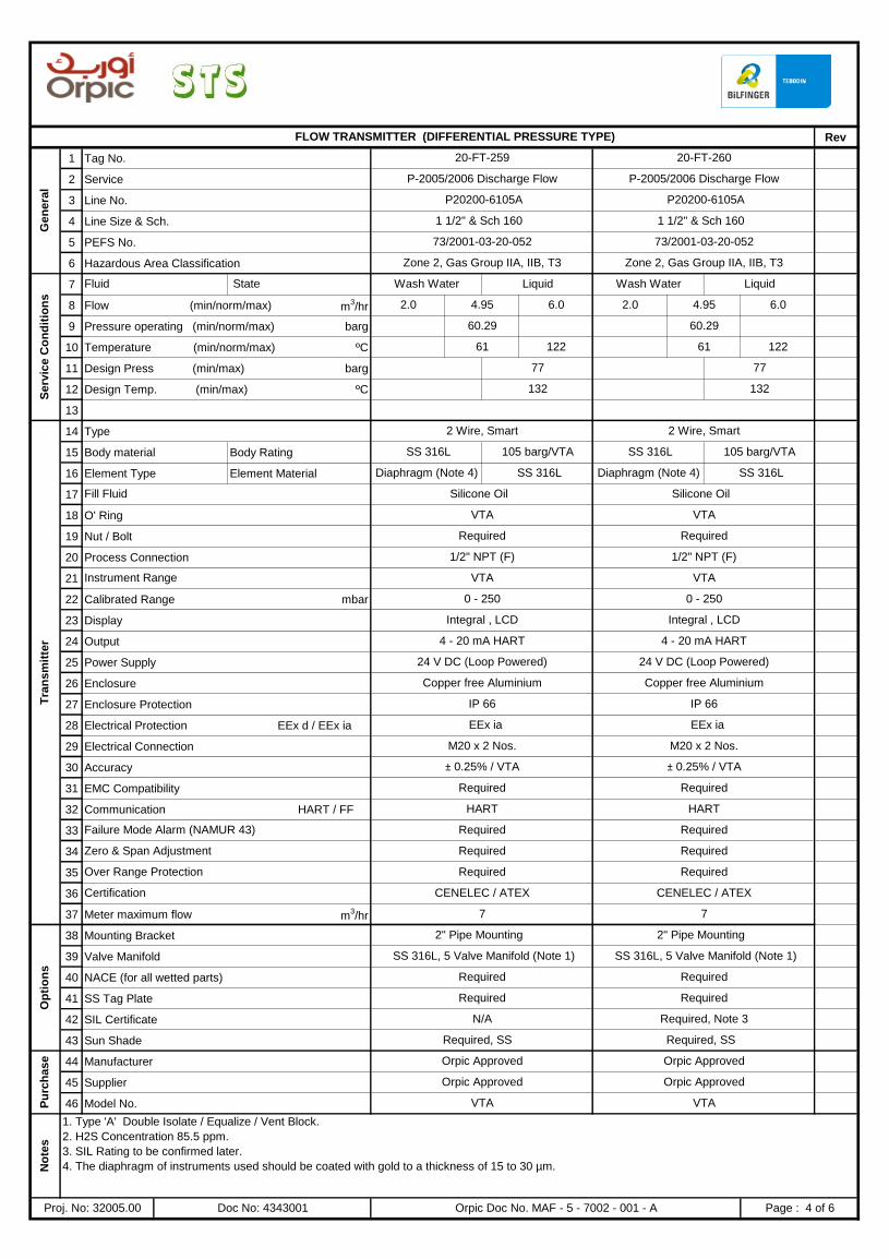
Rev
1 Tag No.
2 Service
3 Line No.
4 Line Size & Sch.
5 PEFS No.
6 Hazardous Area Classification
7
8 Flow (min/norm/max) m3/hr
9 Pressure operating (min/norm/max) barg
10 Temperature (min/norm/max) ºC
11 Design Press (min/max) barg
12 Design Temp. (min/max) ºC
13
14 Type
15 Body material Body Rating
16 Element Type Element Material
17
18 O' Ring
19 Nut / Bolt
20 Process Connection
21
22 Calibrated Range mbar
23 Display
24 Output
25 Power Supply
26 Enclosure
27 Enclosure Protection
28 Electrical Protection EEx d / EEx ia
29 Electrical Connection
30 Accuracy
31 EMC Compatibility
32 Communication HART / FF
33
34
35
36
37 Meter maximum flow m3/hr
38 Mounting Bracket
39 Valve Manifold
40 NACE (for all wetted parts)
41 SS Tag Plate
42 SIL Certificate
43 Sun Shade
44 Manufacturer
45 Supplier
46 Model No.
Fill Fluid Silicone Oil Silicone Oil
77
132
SS 316L 105 barg/VTA
Diaphragm (Note 4) SS 316L Diaphragm (Note 4) SS 316L
No
tes
1. Type 'A' Double Isolate / Equalize / Vent Block.
2. H2S Concentration 85.5 ppm.
3. SIL Rating to be confirmed later.
4. The diaphragm of instruments used should be coated with gold to a thickness of 15 to 30 µm.
Proj. No: 32005.00 Doc No: 4343001 Orpic Doc No. MAF - 5 - 7002 - 001 - A Page : 4 of 6
Pu
rch
ase Orpic Approved Orpic Approved
Orpic Approved Orpic Approved
VTA VTA
7 7
Op
tio
ns
2" Pipe Mounting 2" Pipe Mounting
SS 316L, 5 Valve Manifold (Note 1) SS 316L, 5 Valve Manifold (Note 1)
Required Required
Required Required
N/A Required, Note 3
Required, SS Required, SS
Over Range Protection Required Required
Certification CENELEC / ATEX CENELEC / ATEX
Failure Mode Alarm (NAMUR 43) Required Required
Zero & Span Adjustment Required Required
Required Required
1/2" NPT (F) 1/2" NPT (F)
± 0.25% / VTA ± 0.25% / VTA
Required Required
HART HART
IP 66 IP 66
EEx ia EEx ia
M20 x 2 Nos. M20 x 2 Nos.
0 - 250 0 - 250
4 - 20 mA HART 4 - 20 mA HART
Serv
ice C
on
dit
ion
s
Fluid State Wash Water Liquid Wash Water
Instrument Range VTA VTA
Tra
nsm
itte
r
2 Wire, Smart 2 Wire, Smart
VTA
Integral , LCD Integral , LCD
24 V DC (Loop Powered) 24 V DC (Loop Powered)
Copper free Aluminium Copper free Aluminium
VTA
SS 316L 105 barg/VTA
FLOW TRANSMITTER (DIFFERENTIAL PRESSURE TYPE)
Gen
era
l
20-FT-259 20-FT-260
P-2005/2006 Discharge Flow P-2005/2006 Discharge Flow
P20200-6105A P20200-6105A
1 1/2" & Sch 160 1 1/2" & Sch 160
73/2001-03-20-052 73/2001-03-20-052
Zone 2, Gas Group IIA, IIB, T3 Zone 2, Gas Group IIA, IIB, T3
Liquid
2.0 4.95 6.0 2.0 4.95 6.0
77
60.29 60.29
61 122 12261
132
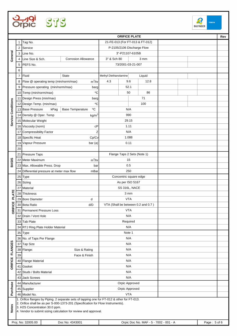
Rev
1 Tag No.
2 Service
3 Line No.
4 Line Size & Sch.
5 PEFS No.
6
7
8 Flow @ operating temp (min/norm/max) m3/hr
9 Pressure operating (min/norm/max) barg
10 Temp (min/norm/max) ºC
11 Design Press (min/max) barg
12 Design Temp. (min/max) ºC
13
14 Density @ Oper. Temp kg/m3
15 Molecular Weight
16 Viscosity (norm) cP
17 Compressibility Factor Z
18 Specific Heat Cp/Cv
19
20
21 Pressure Taps
22 Meter Maximum m3/hr
23 Max. Allowable Press. Drop bar
24 Differential pressure at meter max flow mBar
25 Type
26 Sizing
27 Material
28 Thickness
29 Bore Diameter d
30 Beta Ratio d/D
31 Permanent Pressure Loss kPa
32 Drain / Vent Hole
33 Tab Plate
34 RTJ Ring Plate Holder Material
35 Type
36 No. of Taps Per Flange
37 Tap Size
38 Flange: Size & Rating
39 Face & Finish
40 Flange Material
41 Gasket
42 Studs / Bolts Material
43 Jack Screws
44 Manufacturer
45 Supplier
46 Model No.
No
tes
1. Orifice flanges by Piping. 2 separate sets of tapping one for FT-012 & other for FT-013.
2. Orifice shall be as per S-000-1373-201 (Specification for Flow Instruments).
3. H2S Concentration 30.0 ppm.
4. Vendor to submit sizing calculation for review and approval.
Proj. No: 32005.00 Doc No: 4343001 Orpic Doc No. MAF - 5 - 7002 - 001 - A Page : 5 of 6
N/A
Pu
rch
ase Orpic Approved
Orpic Approved
VTA
OR
IFIC
E F
LA
NG
ES
Note 1
N/A
N/A
N/A
N/A
N/A
N/A
N/A
VTA
VTA (Shall be between 0.2 and 0.7 )
VTA
N/A
OR
IFIC
E P
LA
TE
Concentric square edge
As per ISO 5167
SS 316L, NACE
3 mm
N/A
Required
BA
SIS
Flange Taps 2 Sets (Note 1)
15
0.5
250
1.088
Vapour Pressure bar (a) 0.11
29.15
1.11
N/A
Base Pressure kPag Base Temperature ºC N/A
990
71
100
Serv
ice C
on
dit
ion
s
Fluid State Methyl Diethanolamine Liquid
4.3
50 86
9.6 12.8
52.1
ORIFICE PLATE
Gen
era
l
21-FE-013 (For FT-013 & FT-012)
P-2105/2106 Discharge Flow
3"-P21107-6105B
Corrosion Allowance 3" & Sch 80 3 mm
73/2001-03-21-007
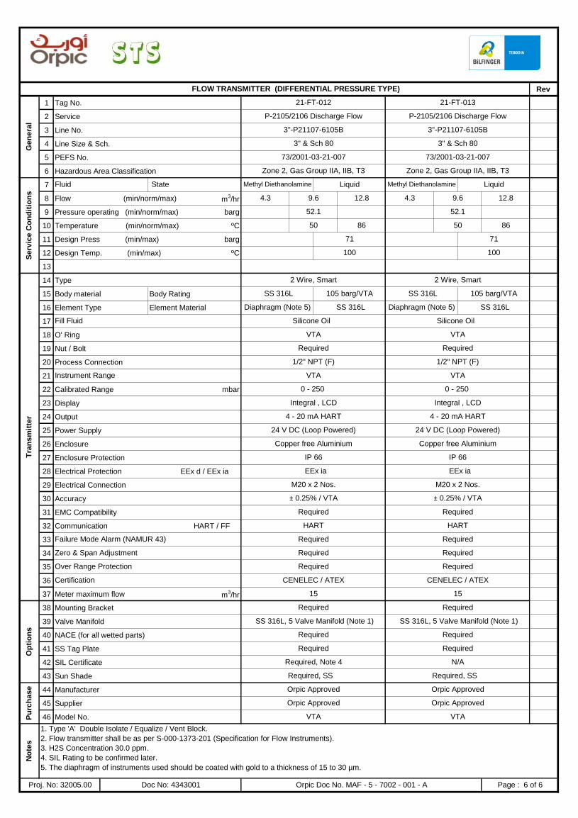
Rev
1 Tag No.
2 Service
3 Line No.
4 Line Size & Sch.
5 PEFS No.
6 Hazardous Area Classification
7
8 Flow (min/norm/max) m3/hr
9 Pressure operating (min/norm/max) barg
10 Temperature (min/norm/max) ºC
11 Design Press (min/max) barg
12 Design Temp. (min/max) ºC
13
14 Type
15 Body material Body Rating
16 Element Type Element Material
17
18 O' Ring
19 Nut / Bolt
20 Process Connection
21
22 Calibrated Range mbar
23 Display
24 Output
25 Power Supply
26 Enclosure
27 Enclosure Protection
28 Electrical Protection EEx d / EEx ia
29 Electrical Connection
30 Accuracy
31 EMC Compatibility
32 Communication HART / FF
33
34
35
36
37 Meter maximum flow m3/hr
38 Mounting Bracket
39 Valve Manifold
40 NACE (for all wetted parts)
41 SS Tag Plate
42 SIL Certificate
43 Sun Shade
44 Manufacturer
45 Supplier
46 Model No. VTA VTA
No
tes
1. Type 'A' Double Isolate / Equalize / Vent Block.
2. Flow transmitter shall be as per S-000-1373-201 (Specification for Flow Instruments).
3. H2S Concentration 30.0 ppm.
4. SIL Rating to be confirmed later.
5. The diaphragm of instruments used should be coated with gold to a thickness of 15 to 30 µm.
Proj. No: 32005.00 Doc No: 4343001 Orpic Doc No. MAF - 5 - 7002 - 001 - A Page : 6 of 6
Required
Required, Note 4 N/A
Required, SS Required, SS
Pu
rch
ase Orpic Approved Orpic Approved
Orpic Approved Orpic Approved
15 15
Op
tio
ns
Required Required
SS 316L, 5 Valve Manifold (Note 1) SS 316L, 5 Valve Manifold (Note 1)
Required Required
Required
Over Range Protection Required Required
Certification CENELEC / ATEX CENELEC / ATEX
Failure Mode Alarm (NAMUR 43) Required Required
Zero & Span Adjustment Required Required
± 0.25% / VTA ± 0.25% / VTA
Required Required
HART HART
IP 66 IP 66
EEx ia EEx ia
M20 x 2 Nos. M20 x 2 Nos.
24 V DC (Loop Powered) 24 V DC (Loop Powered)
Copper free Aluminium Copper free Aluminium
Instrument Range VTA VTA
0 - 250 0 - 250
Integral , LCD Integral , LCD
Tra
nsm
itte
r
2 Wire, Smart 2 Wire, Smart
SS 316L 105 barg/VTA SS 316L 105 barg/VTA
Diaphragm (Note 5)
Fill Fluid Silicone Oil Silicone Oil
VTA VTA
Required Required
1/2" NPT (F) 1/2" NPT (F)
SS 316L Diaphragm (Note 5) SS 316L
4 - 20 mA HART 4 - 20 mA HART
100
52.1
50 86 50 86
Liquid
4.3 9.6 12.8 4.3 9.6 12.8
Serv
ice C
on
dit
ion
s
Fluid State Methyl Diethanolamine Liquid Methyl Diethanolamine
52.1
71 71
100
3" & Sch 80 3" & Sch 80
73/2001-03-21-007 73/2001-03-21-007
Zone 2, Gas Group IIA, IIB, T3 Zone 2, Gas Group IIA, IIB, T3
FLOW TRANSMITTER (DIFFERENTIAL PRESSURE TYPE)
Gen
era
l
21-FT-012 21-FT-013
P-2105/2106 Discharge Flow P-2105/2106 Discharge Flow
3"-P21107-6105B 3"-P21107-6105B
PROJECT: DD for HP Amine and Wash Water Pumps
ISSUED FOR REVIEW
T & P Doc. No. : 4343003 CLIENT DOC. NO.
MAF - 5 - 7004- 001 - B
ORPIC APPROVAL
LOCATION : MAF Refinery
AREA : DHDS / ATU- DHDS
UNIT No. : 2000 / 2100
T & P Proj No. : 32005.00
ISSUED FOR TENDER
REV DATE PREP'D CHK'D APPD DESCRIPTIONPROJ. ENGR. SIGN
A 18-12-16 SAP SVG SVG
B 26-01-17 SAP SVG SVG
INSTRUMENT DATASHEET FOR
PRESSURE & DIFFERENTIAL PRESSURE TRANSMITTERS
DD for HP Amine and Wash Water Pumps
Page 1 of 5
52980508
C2 - Tender document
52980508
SAKET - SVG
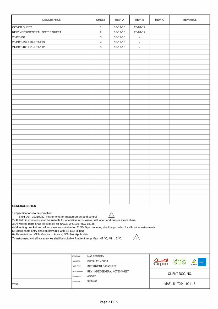
DESCRIPTION : REV / INDEX/GENERAL NOTES SHEET
T&P DOC NO. :
T&P Proj No :
4343003
32005.00
REMARKS
CLIENT DOC. NO.
NOTES MAF - 5 - 7004 - 001 - B
LOCATION : MAF REFINERY
SUB AREA : DHDS / ATU- DHDS
DOC. TYPE : INSTRUMENT DATASHEET
GENERAL NOTES
1) Specifications to be complied
- Shell DEP 32310032_Instruments for measurement and control .
2) All field instruments shall be suitable for operation in corrosive, salt laden and marine atmosphere.
3) All wetted parts shall be suitable for NACE MR0175 / ISO 15156.
4) Mounting bracket and all accessories suitable for 2" NB Pipe mounting shall be provided for all online instruments.
5) Spare cable entry shall be provided with SS EEx 'd' plug.
6) Abbreviations: VTA- Vendor to Advice, N/A- Not Applicable.
7) Instrument and all accessories shall be suitable Ambient temp Max : 47 0C, Min : 5
0C.
21-PDT-108 / 21-PDT-112 5 18-12-16 -
20-PDT-292 / 20-PDT-293 4 18-12-16 -
20-PT-294 3 18-12-16 -
COVER SHEET 1 18-12-16 26-01-17
DESCRIPTION SHEET REV. A REV. B REV. C
REV/INDEX/GENERAL NOTES SHEET 2 18-12-16 26-01-17
B
B
Page 2 OF 5
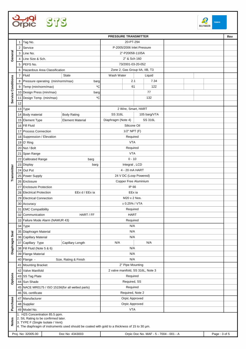
Rev
1 Tag No.
2 Service
3 Line No.
4 Line Size & Sch.
5 PEFS No.
6 Hazardous Area Classification
7
8 Pressure operating (min/norm/max) barg
9 Temp (min/norm/max) ºC
10 Design Press (min/max) barg
11 Design Temp. (min/max) ºC
12
13 Type
14 Body material Body Rating
15 Element Type Element Material
16
17 Process Connection
18
19 O' Ring
20 Nut / Bolt
21 Span Range
22 Calibrated Range barg
23
24 Out Put
25 Power Supply
26 Enclosure
27 Enclosure Protection
28
29 Electrical Connection
30 Accuracy
31 EMC Compatibility
32
33
34 Type
35 Diaphragm Material
36 Capillary Material
37 Capillary Type Capillary Length
38 Fill Fluid (Note 5 & 6)
39 Flange Material
40 Flange - Size, Rating & Finish
41 Mounting Bracket
42 Valve Manifold
43 SS Tag Plate
44 Sun Shade
45 NACE MR0175 / ISO 15156(for all wetted parts)
46 SIL certificate
47 Manufacturer
48 Supplier
49 Model No.
Silicone OilFill Fluid
2 Wire, Smart, HART
SS 316L 105 barg/VTA
Diaphragm (Note 4) SS 316L
PRESSURE TRANSMITTER
Gen
era
l
20-PT-294
P-2005/2006 Inlet Pressure
2"-P20058-1105A
2" & Sch 160
73/2001-03-20-052
Zone 2, Gas Group IIA, IIB, T3
Serv
ice C
on
dit
ion
s Fluid State Wash Water Liquid
2.1 7.34
61 122
77
132
VTA
0 - 10
Display barg Integral , LCD
Tra
nsm
itte
r
1/2" NPT (F)
Suppression / Elevation Required
VTA
Required
IP 66
Electrical Protection EEx d / EEx ia EEx ia
M20 x 2 Nos.
4 - 20 mA HART
24 V DC (Loop Powered)
Copper Free Aluminium
Failure Mode Alarm (NAMUR 43) Required
± 0.25% / VTA
Required
Communication HART / FF HART
N/A
N/A
N/A
2" Pipe Mounting
Dia
ph
rag
m S
eal
N/A
N/A
N/A N/A
N/A
No
tes
1. H2S Concentration 85.5 ppm.
2. SIL Rating to be confirmed later.
3. TYPE F (Single Isolate / Vent)
4. The diaphragm of instruments used should be coated with gold to a thickness of 15 to 30 µm.
Proj. No: 32005.00 Doc No: 4343003 Orpic Doc No. MAF - 5 - 7004 - 001 - A Page : 3 of 5
Required
Required, Note 2
Pu
rch
ase Orpic Approved
Orpic Approved
VTA
Op
tio
ns
2 valve manifold, SS 316L, Note 3
Required
Required, SS
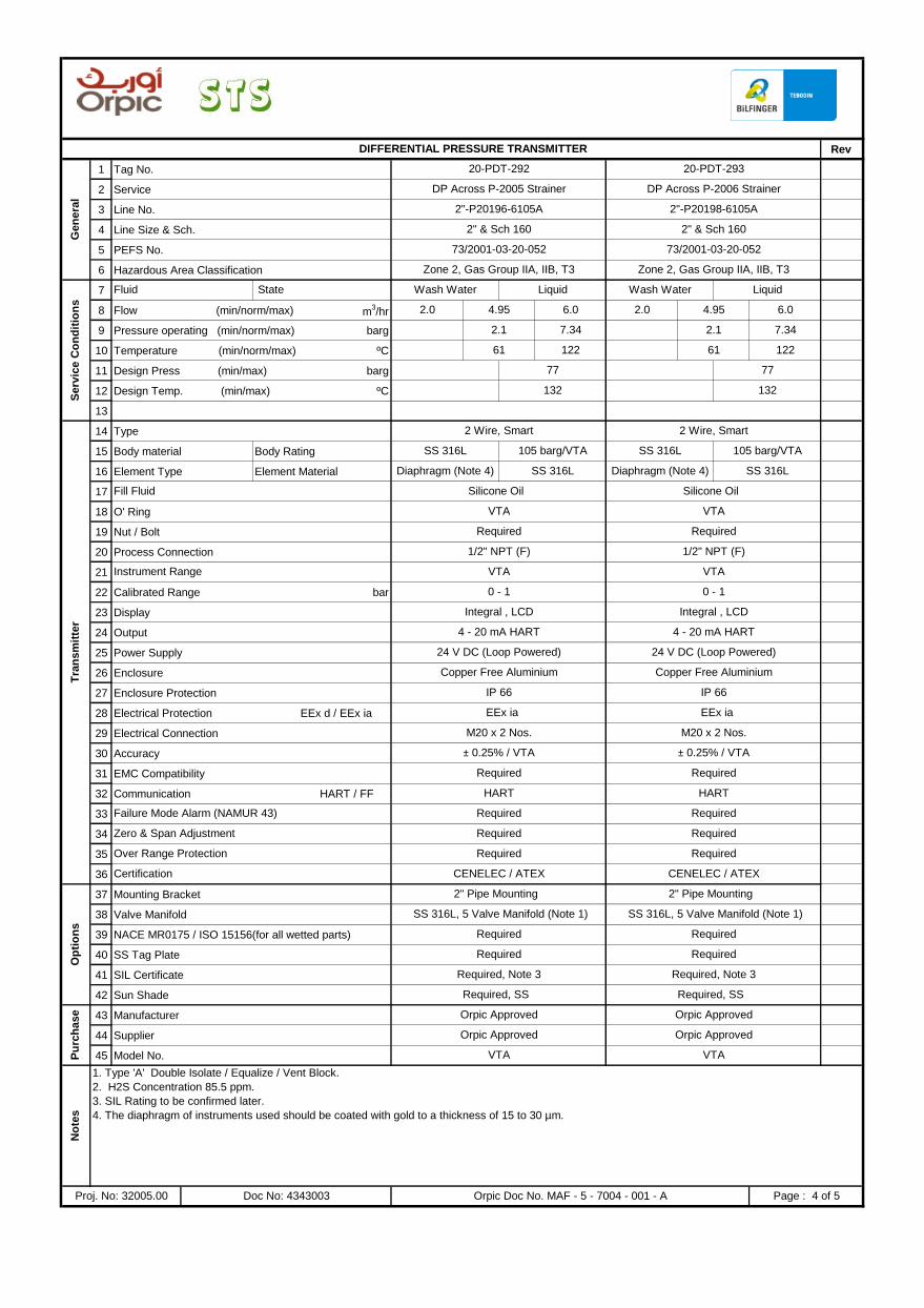
Rev
1 Tag No.
2 Service
3 Line No.
4 Line Size & Sch.
5 PEFS No.
6 Hazardous Area Classification
7
8 Flow (min/norm/max) m3/hr
9 Pressure operating (min/norm/max) barg
10 Temperature (min/norm/max) ºC
11 Design Press (min/max) barg
12 Design Temp. (min/max) ºC
13
14 Type
15 Body material Body Rating
16 Element Type Element Material
17
18 O' Ring
19 Nut / Bolt
20 Process Connection
21
22 Calibrated Range bar
23 Display
24 Output
25 Power Supply
26 Enclosure
27 Enclosure Protection
28 Electrical Protection EEx d / EEx ia
29 Electrical Connection
30 Accuracy
31 EMC Compatibility
32 Communication HART / FF
33
34
35
36
37 Mounting Bracket
38 Valve Manifold
39 NACE MR0175 / ISO 15156(for all wetted parts)
40 SS Tag Plate
41 SIL Certificate
42 Sun Shade
43 Manufacturer
44 Supplier
45 Model No.
No
tes
1. Type 'A' Double Isolate / Equalize / Vent Block.
2. H2S Concentration 85.5 ppm.
3. SIL Rating to be confirmed later.
4. The diaphragm of instruments used should be coated with gold to a thickness of 15 to 30 µm.
Proj. No: 32005.00 Doc No: 4343003 Orpic Doc No. MAF - 5 - 7004 - 001 - A Page : 4 of 5
Required
Required, Note 3 Required, Note 3
Required, SS Required, SS
Pu
rch
ase Orpic Approved Orpic Approved
Orpic Approved Orpic Approved
Op
tio
ns
2" Pipe Mounting 2" Pipe Mounting
SS 316L, 5 Valve Manifold (Note 1) SS 316L, 5 Valve Manifold (Note 1)
Required Required
Required
VTA VTA
Over Range Protection Required Required
Certification CENELEC / ATEX CENELEC / ATEX
Failure Mode Alarm (NAMUR 43) Required Required
Zero & Span Adjustment Required Required
± 0.25% / VTA ± 0.25% / VTA
Required Required
HART HART
IP 66 IP 66
EEx ia EEx ia
M20 x 2 Nos. M20 x 2 Nos.
Copper Free Aluminium
Instrument Range VTA VTA
0 - 1 0 - 1
Integral , LCD Integral , LCD
Fill Fluid Silicone Oil Silicone Oil
Tra
nsm
itte
r
2 Wire, Smart 2 Wire, Smart
SS 316L 105 barg/VTA SS 316L 105 barg/VTA
Diaphragm (Note 4)
VTA VTA
Required Required
1/2" NPT (F) 1/2" NPT (F)
SS 316L Diaphragm (Note 4) SS 316L
4 - 20 mA HART 4 - 20 mA HART
24 V DC (Loop Powered) 24 V DC (Loop Powered)
Copper Free Aluminium
132
2.1 7.34
61 122 61 122
Liquid
2.0 4.95 6.0 2.0 4.95 6.0
Serv
ice C
on
dit
ion
s
Fluid State Wash Water Liquid Wash Water
2.1 7.34
77 77
132
2" & Sch 160 2" & Sch 160
73/2001-03-20-052 73/2001-03-20-052
Zone 2, Gas Group IIA, IIB, T3 Zone 2, Gas Group IIA, IIB, T3
DIFFERENTIAL PRESSURE TRANSMITTER
Gen
era
l
20-PDT-292 20-PDT-293
DP Across P-2005 Strainer DP Across P-2006 Strainer
2"-P20196-6105A 2"-P20198-6105A
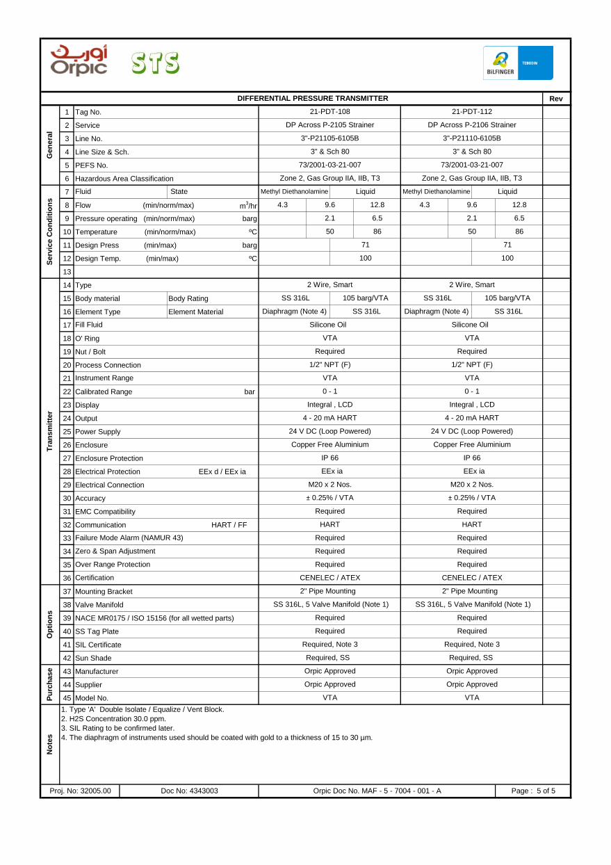
Rev
1 Tag No.
2 Service
3 Line No.
4 Line Size & Sch.
5 PEFS No.
6 Hazardous Area Classification
7
8 Flow (min/norm/max) m3/hr
9 Pressure operating (min/norm/max) barg
10 Temperature (min/norm/max) ºC
11 Design Press (min/max) barg
12 Design Temp. (min/max) ºC
13
14 Type
15 Body material Body Rating
16 Element Type Element Material
17
18 O' Ring
19 Nut / Bolt
20 Process Connection
21
22 Calibrated Range bar
23 Display
24 Output
25 Power Supply
26 Enclosure
27 Enclosure Protection
28 Electrical Protection EEx d / EEx ia
29 Electrical Connection
30 Accuracy
31 EMC Compatibility
32 Communication HART / FF
33
34
35
36
37 Mounting Bracket
38 Valve Manifold
39 NACE MR0175 / ISO 15156 (for all wetted parts)
40 SS Tag Plate
41 SIL Certificate
42 Sun Shade
43 Manufacturer
44 Supplier
45 Model No.
No
tes
1. Type 'A' Double Isolate / Equalize / Vent Block.
2. H2S Concentration 30.0 ppm.
3. SIL Rating to be confirmed later.
4. The diaphragm of instruments used should be coated with gold to a thickness of 15 to 30 µm.
Proj. No: 32005.00 Doc No: 4343003 Orpic Doc No. MAF - 5 - 7004 - 001 - A Page : 5 of 5
Required
Required, Note 3 Required, Note 3
Required, SS Required, SS
Pu
rch
ase Orpic Approved Orpic Approved
Orpic Approved Orpic Approved
Op
tio
ns
2" Pipe Mounting 2" Pipe Mounting
SS 316L, 5 Valve Manifold (Note 1) SS 316L, 5 Valve Manifold (Note 1)
Required Required
Required
VTA VTA
Over Range Protection Required Required
Certification CENELEC / ATEX CENELEC / ATEX
Failure Mode Alarm (NAMUR 43) Required Required
Zero & Span Adjustment Required Required
± 0.25% / VTA ± 0.25% / VTA
Required Required
HART HART
IP 66 IP 66
EEx ia EEx ia
M20 x 2 Nos. M20 x 2 Nos.
Copper Free Aluminium
Instrument Range VTA VTA
0 - 1 0 - 1
Integral , LCD Integral , LCD
Fill Fluid Silicone Oil Silicone Oil
Tra
nsm
itte
r
2 Wire, Smart 2 Wire, Smart
SS 316L 105 barg/VTA SS 316L 105 barg/VTA
Diaphragm (Note 4)
VTA VTA
Required Required
1/2" NPT (F) 1/2" NPT (F)
SS 316L Diaphragm (Note 4) SS 316L
4 - 20 mA HART 4 - 20 mA HART
24 V DC (Loop Powered) 24 V DC (Loop Powered)
Copper Free Aluminium
100
2.1 6.5
50 86 50 86
Liquid
4.3 9.6 12.8 4.3 9.6 12.8
Serv
ice C
on
dit
ion
s
Fluid State Methyl Diethanolamine Liquid Methyl Diethanolamine
2.1 6.5
71 71
100
3" & Sch 80 3" & Sch 80
73/2001-03-21-007 73/2001-03-21-007
Zone 2, Gas Group IIA, IIB, T3 Zone 2, Gas Group IIA, IIB, T3
DIFFERENTIAL PRESSURE TRANSMITTER
Gen
era
l
21-PDT-108 21-PDT-112
DP Across P-2105 Strainer DP Across P-2106 Strainer
3"-P21105-6105B 3"-P21110-6105B
PROJECT: DD for HP Amine and Wash Water Pumps
INSTRUMENT DATASHEET FOR
PRESSURE GAUGES
DD for HP Amine and Wash Water Pumps
B 26-01-17 SAP SVG SVG ISSUED FOR TENDER
REV DATE PREP'D CHK'D APPD DESCRIPTIONPROJ. ENGR. SIGN
A 18-12-16 SAP SVG SVG ISSUED FOR REVIEW
T & P Doc. No. : 4343002 CLIENT DOC. NO.
MAF - 5 - 7003 - 001 - B
ORPIC APPROVAL
LOCATION : MAF Refinery
AREA : DHDS / ATU- DHDS
UNIT No. : 2000 / 2100
T & P Proj No. : 32005.00
Page 1 of 6
52980508
C2 - Tender document
52980508
SAKET - SVG
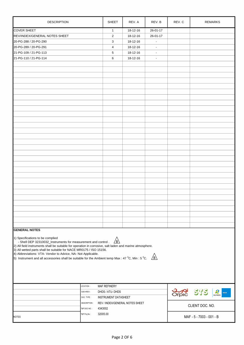
DESCRIPTION : REV / INDEX/GENERAL NOTES SHEET
T&P DOC NO. :
T&P Proj No :
4343002
32005.00
COVER SHEET 1 18-12-16 26-01-17
DESCRIPTION SHEET REV. A REV. B REV. C
REV/INDEX/GENERAL NOTES SHEET 2 18-12-16 26-01-17
20-PG-289 / 20-PG-291 4 18-12-16 -
20-PG-288 / 20-PG-290 3 18-12-16 -
21-PG-109 / 21-PG-113 5 18-12-16 -
21-PG-110 / 21-PG-114 6 18-12-16 -
CLIENT DOC. NO.
NOTES MAF - 5 - 7003 - 001 - B
LOCATION : MAF REFINERY
SUB AREA : DHDS / ATU- DHDS
DOC. TYPE : INSTRUMENT DATASHEET
GENERAL NOTES
1) Specifications to be complied
- Shell DEP 32310032_Instruments for measurement and control .
2) All field instruments shall be suitable for operation in corrosive, salt laden and marine atmosphere.
3) All wetted parts shall be suitable for NACE MR0175 / ISO 15156.
4) Abbreviations: VTA- Vendor to Advice, NA- Not Applicable.
5) Instrument and all accessories shall be suitable for the Ambient temp Max : 47 0C, Min : 5
0C.
REMARKS
B
B
Page 2 OF 6
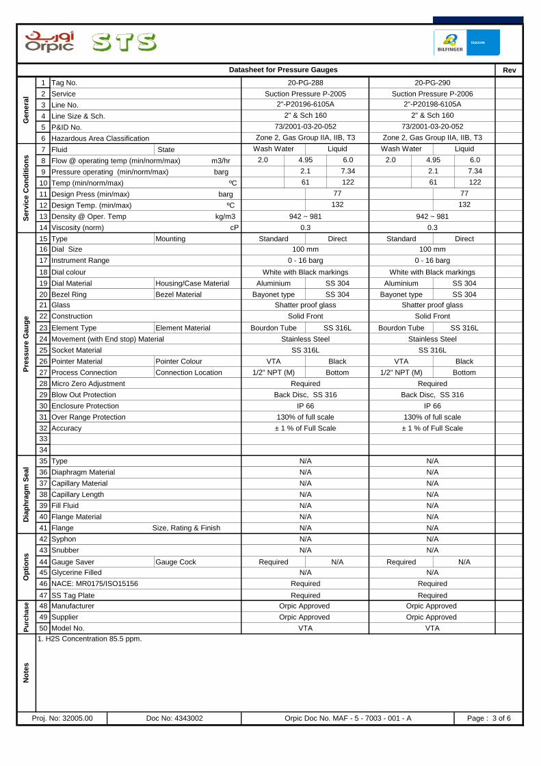
Rev
1 Tag No.
2 Service
3 Line No.
4 Line Size & Sch.
5 P&ID No.
6 Hazardous Area Classification
7
8
9
10
11
12
13
14
15
16
17
18
19
20
21
22
23
24
25
26
27
28
29
30
31
32
33
34
35 Type
36 Diaphragm Material
37 Capillary Material
38 Capillary Length
39 Fill Fluid
40 Flange Material
41 Flange Size, Rating & Finish
42 Syphon
43 Snubber
44
45 Glycerine Filled
46 NACE: MR0175/ISO15156
47 SS Tag Plate
48 Manufacturer
49 Supplier
50 Model No.
2" & Sch 160 2" & Sch 160
73/2001-03-20-052 73/2001-03-20-052
Zone 2, Gas Group IIA, IIB, T3 Zone 2, Gas Group IIA, IIB, T3
Datasheet for Pressure Gauges
Gen
era
l
20-PG-288 20-PG-290
Suction Pressure P-2005 Suction Pressure P-2006
2"-P20196-6105A 2"-P20198-6105A
Liquid
Flow @ operating temp (min/norm/max) m3/hr 2.0 4.95 6.0 2.0 4.95 6.0
Serv
ice C
on
dit
ion
s
Fluid State Wash Water Liquid Wash Water
Pressure operating (min/norm/max) barg 2.1 7.34 2.1 7.34
Temp (min/norm/max) ºC 61 122 61 122
Density @ Oper. Temp kg/m3 942 ~ 981 942 ~ 981
Viscosity (norm) cP 0.3 0.3
Design Press (min/max) barg 77 77
Design Temp. (min/max) ºC 132 132
Direct
Dial Size 100 mm 100 mm
Instrument Range 0 - 16 barg 0 - 16 barg
Pre
ssu
re G
au
ge
Type Mounting Standard Direct Standard
Dial colour White with Black markings White with Black markings
Dial Material Housing/Case Material Aluminium SS 304 Aluminium SS 304
Bezel Ring Bezel Material Bayonet type SS 304 Bayonet type
Element Type Element Material Bourdon Tube SS 316L Bourdon Tube SS 316L
SS 304
Glass Shatter proof glass Shatter proof glass
Construction Solid Front Solid Front
Pointer Material Pointer Colour VTA Black VTA Black
Movement (with End stop) Material Stainless Steel Stainless Steel
Socket Material SS 316L SS 316L
Micro Zero Adjustment Required Required
Blow Out Protection Back Disc, SS 316 Back Disc, SS 316
Process Connection Connection Location 1/2" NPT (M) Bottom 1/2" NPT (M) Bottom
Accuracy ± 1 % of Full Scale ± 1 % of Full Scale
Enclosure Protection IP 66 IP 66
Over Range Protection 130% of full scale 130% of full scale
N/A
N/A N/A
N/A N/A
Op
tio
ns
N/A N/A
N/A N/A
Dia
ph
rag
m S
eal
N/A N/A
N/A N/A
N/A N/A
N/A N/A
N/A
N/A N/A
Required Required
Required Required
Gauge Saver Gauge Cock Required N/A Required N/A
No
tes
1. H2S Concentration 85.5 ppm.
Proj. No: 32005.00 Doc No: 4343002 Orpic Doc No. MAF - 5 - 7003 - 001 - A Page : 3 of 6
Pu
rch
ase Orpic Approved Orpic Approved
Orpic Approved Orpic Approved
VTA VTA

Rev
1 Tag No.
2 Service
3 Line No.
4 Line Size & Sch.
5 P&ID No.
6 Hazardous Area Classification
7
8
9
10
11
12
13
14
15
16
17
18
19
20
21
22
23
24
25
26
27
28
29
30
31
32
33
34
35 Type
36 Diaphragm Material
37 Capillary Material
38 Capillary Length
39 Fill Fluid
40 Flange Material
41 Flange Size, Rating & Finish
42 Syphon
43 Snubber
44
45 Glycerine Filled
46 NACE: MR0175/ISO15156
47 SS Tag Plate
48 Manufacturer
49 Supplier
50 Model No.
1 1/2" & Sch 160 1 1/2" & Sch 160
73/2001-03-20-052 73/2001-03-20-052
Zone 2, Gas Group IIA, IIB, T3 Zone 2, Gas Group IIA, IIB, T3
Datasheet for Pressure Gauges
Gen
era
l
20-PG-289 20-PG-291
Discharge Pressure P-2005 Discharge Pressure P-2006
1 1/2"- P20197-6105A 1 1/2"- P20199-6105A
Liquid
Flow @ operating temp (min/norm/max) m3/hr 2.0 4.95 6.0 2.0 4.95 6.0
Serv
ice C
on
dit
ion
s
Fluid State Wash Water Liquid Wash Water
Pressure operating (min/norm/max) barg 60.29 60.29
Temp (min/norm/max) ºC 61 122 61 122
Density @ Oper. Temp kg/m3 942 ~ 981 942 ~ 981
Viscosity (norm) cP 0.3 0.3
Design Press (min/max) barg 77 77
Design Temp. (min/max) ºC 132 132
Direct
Dial Size 100 mm 100 mm
Instrument Range 0 - 100 barg 0 - 100 barg
Pre
ssu
re G
au
ge
Type Mounting Standard Direct Standard
Dial colour White with Black markings White with Black markings
Dial Material Housing/Case Material Aluminium SS 304 Aluminium SS 304
Bezel Ring Bezel Material Bayonet type SS 304 Bayonet type
Element Type Element Material Bourdon Tube SS 316L Bourdon Tube SS 316L
SS 304
Glass Shatter proof glass Shatter proof glass
Construction Solid Front Solid Front
Pointer Material Pointer Colour VTA Black VTA Black
Movement (with End stop) Material Stainless Steel Stainless Steel
Socket Material SS 316L SS 316L
Micro Zero Adjustment Required Required
Blow Out Protection Back Disc, SS 316 Back Disc, SS 316
Process Connection Connection Location 1/2" NPT (M) Bottom 1/2" NPT (M) Bottom
Accuracy ± 1 % of Full Scale ± 1 % of Full Scale
Enclosure Protection IP 66 IP 66
Over Range Protection 130% of full scale 130% of full scale
N/A
N/A N/A
N/A N/A
Op
tio
ns
N/A N/A
N/A N/A
Dia
ph
rag
m S
eal
N/A N/A
N/A N/A
N/A N/A
N/A N/A
N/A
N/A N/A
Required Required
Required Required
Gauge Saver Gauge Cock N/A N/A N/A N/A
No
tes
1. H2S Concentration 85.5 ppm.
Proj. No: 32005.00 Doc No: 4343002 Orpic Doc No. MAF - 5 - 7003 - 001 - A Page : 4 of 6
Pu
rch
ase Orpic Approved Orpic Approved
Orpic Approved Orpic Approved
VTA VTA
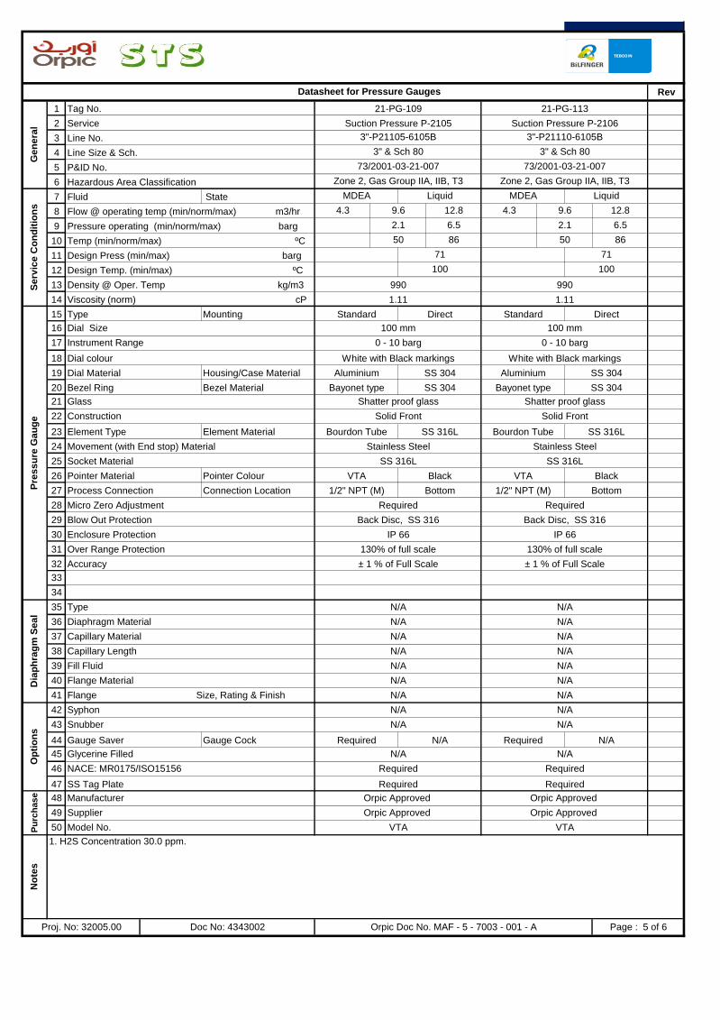
Rev
1 Tag No.
2 Service
3 Line No.
4 Line Size & Sch.
5 P&ID No.
6 Hazardous Area Classification
7
8
9
10
11
12
13
14
15
16
17
18
19
20
21
22
23
24
25
26
27
28
29
30
31
32
33
34
35 Type
36 Diaphragm Material
37 Capillary Material
38 Capillary Length
39 Fill Fluid
40 Flange Material
41 Flange Size, Rating & Finish
42 Syphon
43 Snubber
44
45 Glycerine Filled
46 NACE: MR0175/ISO15156
47 SS Tag Plate
48 Manufacturer
49 Supplier
50 Model No.
3" & Sch 80 3" & Sch 80
73/2001-03-21-007 73/2001-03-21-007
Zone 2, Gas Group IIA, IIB, T3 Zone 2, Gas Group IIA, IIB, T3
Datasheet for Pressure Gauges
Ge
ne
ral
21-PG-109 21-PG-113
Suction Pressure P-2105 Suction Pressure P-2106
3"-P21105-6105B 3"-P21110-6105B
Liquid
Flow @ operating temp (min/norm/max) m3/hr 4.3 9.6 12.8 4.3 9.6 12.8
Se
rvic
e C
on
dit
ion
s
Fluid State MDEA Liquid MDEA
Pressure operating (min/norm/max) barg 2.1 6.5 2.1 6.5
Temp (min/norm/max) ºC 50 86 50 86
Density @ Oper. Temp kg/m3 990 990
Viscosity (norm) cP 1.11 1.11
Design Press (min/max) barg 71 71
Design Temp. (min/max) ºC 100 100
Direct
Dial Size 100 mm 100 mm
Instrument Range 0 - 10 barg 0 - 10 barg
Pre
ss
ure
Ga
ug
e
Type Mounting Standard Direct Standard
Dial colour White with Black markings White with Black markings
Dial Material Housing/Case Material Aluminium SS 304 Aluminium SS 304
Bezel Ring Bezel Material Bayonet type SS 304 Bayonet type
Element Type Element Material Bourdon Tube SS 316L Bourdon Tube SS 316L
SS 304
Glass Shatter proof glass Shatter proof glass
Construction Solid Front Solid Front
Pointer Material Pointer Colour VTA Black VTA Black
Movement (with End stop) Material Stainless Steel Stainless Steel
Socket Material SS 316L SS 316L
Micro Zero Adjustment Required Required
Blow Out Protection Back Disc, SS 316 Back Disc, SS 316
Process Connection Connection Location 1/2" NPT (M) Bottom 1/2" NPT (M) Bottom
Accuracy ± 1 % of Full Scale ± 1 % of Full Scale
Enclosure Protection IP 66 IP 66
Over Range Protection 130% of full scale 130% of full scale
N/A
N/A N/A
N/A N/A
Op
tio
ns
N/A N/A
N/A N/A
Dia
ph
rag
m S
ea
l
N/A N/A
N/A N/A
N/A N/A
N/A N/A
N/A
N/A N/A
Required Required
Required Required
Gauge Saver Gauge Cock Required N/A Required N/A
No
tes
1. H2S Concentration 30.0 ppm.
Proj. No: 32005.00 Doc No: 4343002 Orpic Doc No. MAF - 5 - 7003 - 001 - A Page : 5 of 6
Pu
rch
as
e Orpic Approved Orpic Approved
Orpic Approved Orpic Approved
VTA VTA

Rev
1 Tag No.
2 Service
3 Line No.
4 Line Size & Sch.
5 P&ID No.
6 Hazardous Area Classification
7
8
9
10
11
12
13
14
15
16
17
18
19
20
21
22
23
24
25
26
27
28
29
30
31
32
33
34
35 Type
36 Diaphragm Material
37 Capillary Material
38 Capillary Length
39 Fill Fluid
40 Flange Material
41 Flange Size, Rating & Finish
42 Syphon
43 Snubber
44
45 Glycerine Filled
46 NACE: MR0175/ISO15156
47 SS Tag Plate
48 Manufacturer
49 Supplier
50 Model No.
3" & Sch 80 3" & Sch 80
73/2001-03-21-007 73/2001-03-21-007
Zone 2, Gas Group IIA, IIB, T3 Zone 2, Gas Group IIA, IIB, T3
Datasheet for Pressure Gauges
Gen
era
l
21-PG-110 21-PG-114
Discharge Pressure P-2105 Discharge Pressure P-2106
3"-P21106-6105B 3"-P21111-6105B
Liquid
Flow @ operating temp (min/norm/max) m3/hr 4.3 9.6 12.8 4.3 9.6 12.8
Serv
ice C
on
dit
ion
s
Fluid State MDEA Liquid MDEA
Pressure operating (min/norm/max) barg 52.1 52.1
Temp (min/norm/max) ºC 50 86 50 86
Density @ Oper. Temp kg/m3 990 990
Viscosity (norm) cP 1.11 1.11
Design Press (min/max) barg 71 71
Design Temp. (min/max) ºC 100 100
Direct
Dial Size 100 mm 100 mm
Instrument Range 0 - 100 barg 0 - 100 barg
Pre
ssu
re G
au
ge
Type Mounting Standard Direct Standard
Dial colour White with Black markings White with Black markings
Dial Material Housing/Case Material Aluminium SS 304 Aluminium SS 304
Bezel Ring Bezel Material Bayonet type SS 304 Bayonet type
Element Type Element Material Bourdon Tube SS 316L Bourdon Tube SS 316L
SS 304
Glass Shatter proof glass Shatter proof glass
Construction Solid Front Solid Front
Pointer Material Pointer Colour VTA Black VTA Black
Movement (with End stop) Material Stainless Steel Stainless Steel
Socket Material SS 316L SS 316L
Micro Zero Adjustment Required Required
Blow Out Protection Back Disc, SS 316 Back Disc, SS 316
Process Connection Connection Location 1/2" NPT (M) Bottom 1/2" NPT (M) Bottom
Accuracy ± 1 % of Full Scale ± 1 % of Full Scale
Enclosure Protection IP 66 IP 66
Over Range Protection 130% of full scale 130% of full scale
N/A
N/A N/A
N/A N/A
Op
tio
ns
N/A N/A
N/A N/A
Dia
ph
rag
m S
eal
N/A N/A
N/A N/A
N/A N/A
N/A N/A
N/A
N/A N/A
Required Required
Required Required
Gauge Saver Gauge Cock N/A N/A N/A N/A
No
tes
1. H2S Concentration 30.0 ppm.
Proj. No: 32005.00 Doc No: 4343002 Orpic Doc No. MAF - 5 - 7003 - 001 - A Page : 6 of 6
Pu
rch
ase Orpic Approved Orpic Approved
Orpic Approved Orpic Approved
VTA VTA
PROJECT: DD for Texas Tower
ISSUED FOR TENDERSVG
15/01/17 SAP SVG SVG ISSUED FOR REVIEW
PROJ. ENGR.
APPD
SVG
A
B 25/01/17 SAP
T&P Proj No. : 32015.00 MAF - 5 - 7201 - 001 - B
ORPIC APPROVAL
LOCATION : MAF Refinery
AREA : PLATFORMER UNIT
UNIT NO. : 8200
REV DATE PREP'D DESCRIPTIONSIGN
T & P DOC. NO. : 4343001 CLIENT DOC. NO.
CHK'D
DATASHEET FOR PRESSURE GAUGES
DD for Texas Tower
Page 1 of 3
52980508
C2 - Tender document

DESCRIPTION : REV / DATASHEET INDEX CLIENT DOC. NO.
NOTES T&P DOC NO. : 4343001 MAF - 5 - 7201 - 001 - B
LOCATION : MAF REFINERY
SUB AREA : PLATFORMER UNIT , UNIT 8200
DOC. TYPE : INSTRUMENT DATASHEETS
25/01/201715/01/20173PRESSURE GAUGE
Remarks
COVER SHEET 1 15/01/2017 25/01/2017
DESCRIPTION SHEET REV. A REV.B
REV/INDEX SHEET 2 15/01/2017 25/01/2017
Page 2 of 3
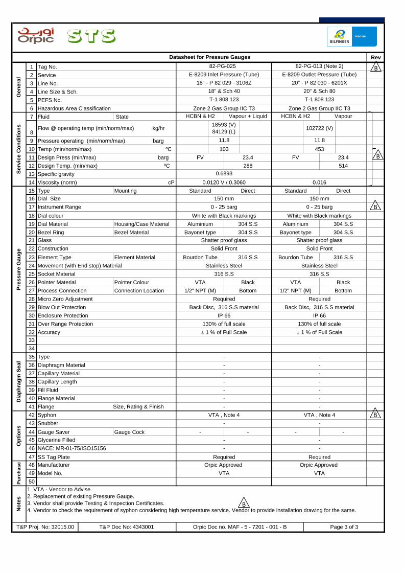
Rev
1
2
3
4
5
6
7
8
9
10
11
12
13
14
15
16
17
18
19
20
21
22
23
24
25
26
27
28
29
30
31
32
33
34
35
36
37
38
39
40
41
42
43
44
45
46
47
48
49
50
18" & Sch 40 20" & Sch 80
T-1 808 123 T-1 808 123
Zone 2 Gas Group IIC T3 Zone 2 Gas Group IIC T3
Datasheet for Pressure Gauges
Gen
era
l
82-PG-025 82-PG-013 (Note 2)
E-8209 Inlet Pressure (Tube) E-8209 Outlet Pressure (Tube)
18" - P 82 029 - 3106Z 20" - P 82 030 - 6201X
Tag No.
Service
Line No.
Line Size & Sch.
PEFS No.
Serv
ice C
on
dit
ion
s
Fluid State HCBN & H2 Vapour + Liquid HCBN & H2
103
FV
0.6893
0.0120 V / 0.3060 0.016
23.4 FV 23.4
288 514
Design Press (min/max) barg
Specific gravity
Viscosity (norm) cP
Direct
Dial Size 150 mm 150 mm
Instrument Range 0 - 25 barg
Pre
ssu
re G
au
ge
Type Mounting Standard Direct Standard
Dial colour White with Black markings
Bezel Ring Bezel Material Bayonet type 304 S.S Bayonet type 304 S.S
Glass Shatter proof glass Shatter proof glass
Dial Material
Movement (with End stop) Material Stainless Steel Stainless Steel
Socket Material 316 S.S 316 S.S
Housing/Case Material Aluminium 304 S.S
Construction Solid Front Solid Front
Element Type Element Material Bourdon Tube 316 S.S Bourdon Tube 316 S.S
Process Connection Connection Location 1/2" NPT (M) Bottom 1/2" NPT (M) Bottom
Pointer Material Pointer Colour VTA Black VTA Black
IP 66
Over Range Protection 130% of full scale 130% of full scale
Micro Zero Adjustment Required Required
Blow Out Protection Back Disc, 316 S.S material Back Disc, 316 S.S material
Op
tio
ns
VTA , Note 4 VTA , Note 4
- -
Dia
ph
rag
m S
eal
- -
- -
- -
- -
-
Required Required
Flange Material
Snubber
Diaphragm Material
Capillary Material
Capillary Length
Fill Fluid
Type
Gauge Saver Gauge Cock - - - -
-
Glycerine Filled
NACE: MR-01-75/ISO15156
SS Tag Plate
Temp (min/norm/max) ºC
Hazardous Area Classification
Flow @ operating temp (min/norm/max) kg/hr
Pressure operating (min/norm/max) barg 11.8
453
Vapour
18593 (V)
84129 (L)
11.8
102722 (V)
No
tes
1. VTA - Vendor to Advise.
2. Replacement of existing Pressure Gauge.
3. Vendor shall provide Testing & Inspection Certificates.
4. Vendor to check the requirement of syphon considering high temperature service. Vendor to provide installation drawing for the same.
T&P Proj. No: 32015.00 T&P Doc No: 4343001
Model No.
Manufacturer
Pu
rch
ase Orpic Approved Orpic Approved
VTA VTA
Orpic Doc no. MAF - 5 - 7201 - 001 - B Page 3 of 3
Design Temp. (min/max) ºC
- -
-
-
Syphon
Flange Size, Rating & Finish
0 - 25 barg
White with Black markings
Aluminium 304 S.S
- -
- -
Accuracy ± 1 % of Full Scale ± 1 % of Full Scale
Enclosure Protection IP 66
B
B
B
B
B
PROJECT: DD for Texas Tower
T&P Proj No. : 32015.00 MAF - 5 - 7202 - 001- B
ORPIC APPROVAL
LOCATION : MAF Refinery
AREA : PLATFORMER UNIT
UNIT NO. : 8200
REV DATE PREP'D DESCRIPTIONPROJ. ENGR. SIGN
T & P DOC. NO. : 4343002 CLIENT DOC. NO.
15/01/17 SAP SVG SVG
CHK'D APPD
ISSUED FOR REVIEW
ISSUED FOR TENDER
A
DATASHEET FOR TEMPERATURE ELEMENTS
DD for Texas Tower
B 25/01/17 SAP SVG SVG
Page 1 of 3
52980508
C2 - Tender document
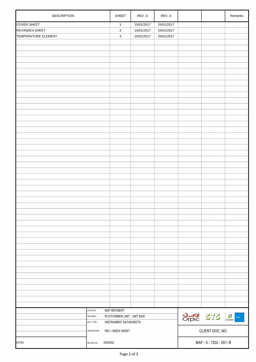
DESCRIPTION : REV / INDEX SHEET CLIENT DOC. NO.
NOTES T&P DOC NO. : 4343002 MAF - 5 - 7202 - 001- B
LOCATION : MAF REFINERY
SUB AREA : PLATFORMER UNIT , UNIT 8200
DOC. TYPE : INSTRUMENT DATASHEETS
TEMPERATURE ELEMENT 3 15/01/2017 25/01/2017
Remarks
COVER SHEET 1 15/01/2017 25/01/2017
DESCRIPTION SHEET REV. A REV. A
REV/INDEX SHEET 2 15/01/2017 25/01/2017
Page 2 of 3
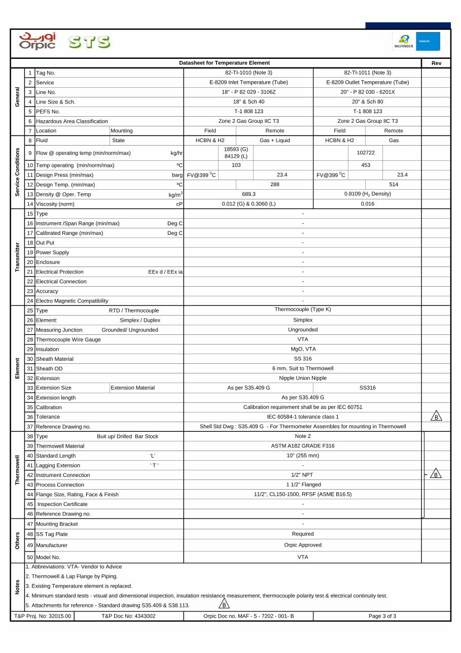
Rev
1 Tag No.
2 Service
3 Line No.
4 Line Size & Sch.
5 PEFS No.
6 Hazardous Area Classification
7
8
9 Flow @ operating temp (min/norm/max) kg/hr
10 Temp operating (min/norm/max) ºC
11 Design Press (min/max) barg
12 Design Temp. (min/max) ºC
13 Density @ Oper. Temp kg/m3
14 Viscosity (norm) cP
15 Type
16 Instrument /Span Range (min/max) Deg C
17 Calibrated Range (min/max) Deg C
18 Out Put
19 Power Supply
20 Enclosure
21 Electrical Protection EEx d / EEx ia
22 Electrical Connection
23 Accuracy
24 Electro Magnetic Compatibility
25 Type RTD / Thermocouple
26 Element: Simplex / Duplex
27 Measuring Junction Grounded/ Ungrounded
28 Thermocouple Wire Gauge
29 Insulation
30 Sheath Material
31 Sheath OD
32 Extension
33
34 Extension length
35 Calibration
36
37 Reference Drawing no.
38 Type Buit up/ Drilled Bar Stock
39 Thermowell Material
40 Standard Length 'L'
41 Lagging Extension ' T '
42 Instrument Connection
43 Process Connection
44 Flange Size, Rating, Face & Finish
45 Inspection Certificate
46 Reference Drawing no.
47 Mounting Bracket
48 SS Tag Plate
49 Manufacturer
50 Model No.
-
Oth
ers
-
Required
Orpic Approved
VTA
T&P Proj. No: 32015.00 T&P Doc No: 4343002
No
tes
1. Abbreviations: VTA- Vendor to Advice
2. Thermowell & Lap Flange by Piping.
3. Existing Temperature element is replaced.
4. Minimum standard tests - visual and dimensional inspection, insulation resistance measurement, thermocouple polarity test & electrical continuity test.
5. Attachments for reference - Standard drawing S35.409 & S38.113.
Orpic Doc no. MAF - 5 - 7202 - 001- B Page 3 of 3
Tolerance IEC 60584-1 tolerance class 1
Shell Std Dwg : S35.409 G - For Thermometer Assembles for mounting in Thermowell
Th
erm
ow
ell
Note 2
ASTM A182 GRADE F316
10" (255 mm)
-
Ele
men
t
1/2" NPT
1 1/2" Flanged
11/2", CL150-1500, RFSF (ASME B16.5)
-
MgO, VTA
SS 316
6 mm, Suit to Thermowell
Nipple Union Nipple
Extension Size Extension Material As per S35.409 G SS316
Thermocouple (Type K)
Simplex
Ungrounded
VTA
-
0.012 (G) & 0.3060 (L) 0.016
As per S35.409 G
Calibration requirement shall be as per IEC 60751
Tra
nsm
itte
r
-
-
-
-
-
-
-
FV@399 0C 23.4 FV@399
0C 23.4
-
-
Gas
18593 (G)
84129 (L)102722
Serv
ice C
on
dit
ion
s
Fluid State HCBN & H2 Gas + Liquid HCBN & H2
103
288 514
689.3 0.8109 (H2 Density)
453
Location Mounting Field Remote Field Remote
20" - P 82 030 - 6201X
18" & Sch 40 20" & Sch 80
T-1 808 123 T-1 808 123
Zone 2 Gas Group IIC T3 Zone 2 Gas Group IIC T3
Datasheet for Temperature Element
Gen
era
l
82-TI-1010 (Note 3) 82-TI-1011 (Note 3)
E-8209 Inlet Temperature (Tube) E-8209 Outlet Temperature (Tube)
18" - P 82 029 - 3106Z
B
B
B
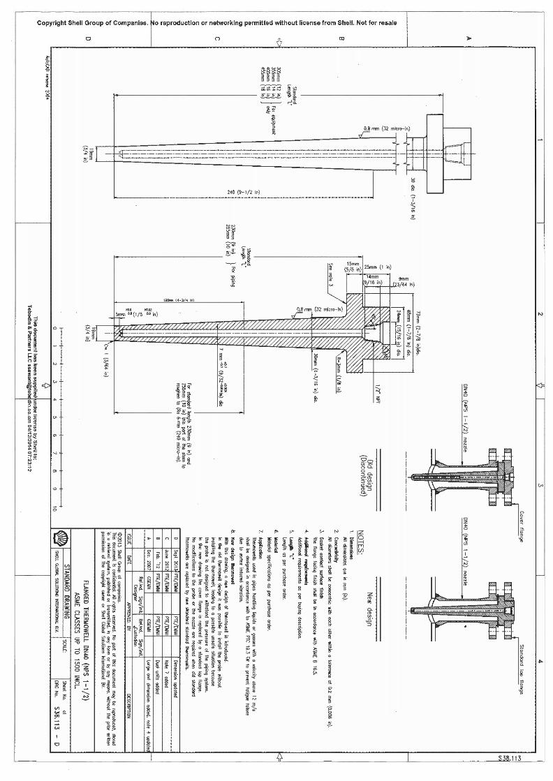


PROJECT: DD for Waste Water System Improvement
ISSUED FOR REVIEW
T & P Doc. No. : 4343002 CLIENT DOC. NO.
MAF - 5 - 7102 - 001 - B
ORPIC APPROVAL
LOCATION : MAF Refinery
AREA : SEWER FLUSHING UNIT
UNIT No. : 8640
T & P Proj No. : 32007.00
ISSUED FOR TENDER
REV DATE PREP'D CHK'D APPD DESCRIPTIONPROJ. ENGR. SIGN
A 23-01-17 SAP SVG SVG
B 31-01-17 SAP SVG SVG
DATASHEET FOR
FLOW ELEMENT & FLOW TRANSMITTER
DD for Waste Water System Improvement
Page 1 of 4
52980508
SAKET - SVG
52980508
C2 - Tender document
52980508
SAKET - SVG
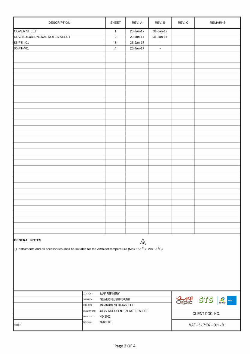
DESCRIPTION : REV / INDEX/GENERAL NOTES SHEET
T&P DOC NO. :
T&P Proj No :
REMARKS
CLIENT DOC. NO.
NOTES MAF - 5 - 7102 - 001 - B
LOCATION : MAF REFINERY
SUB AREA : SEWER FLUSHING UNIT
DOC. TYPE : INSTRUMENT DATASHEET
GENERAL NOTES
1) Instruments and all accessories shall be suitable for the Ambient temperature (Max : 55 0C, Min : 5
0C).
3 23-Jan-17 -
COVER SHEET 1 23-Jan-17 31-Jan-17
DESCRIPTION SHEET REV. A REV. B REV. C
REV/INDEX/GENERAL NOTES SHEET 2 23-Jan-17 31-Jan-17
86-FT-401 4 23-Jan-17 -
86-FE-401
4343002
32007.00
B
Page 2 OF 4
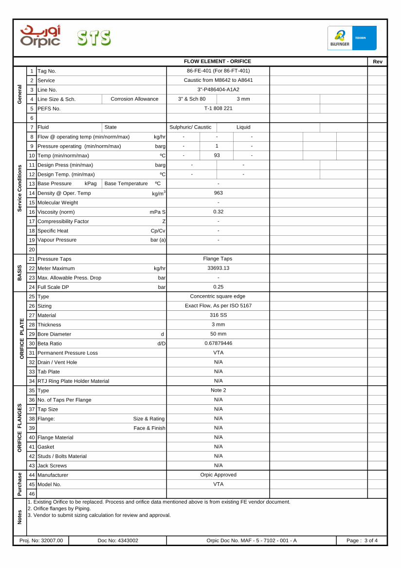
Rev
1 Tag No.
2 Service
3 Line No.
4 Line Size & Sch.
5 PEFS No.
6
7
8 Flow @ operating temp (min/norm/max) kg/hr
9 Pressure operating (min/norm/max) barg
10 Temp (min/norm/max) ºC
11 Design Press (min/max) barg
12 Design Temp. (min/max) ºC
13
14 Density @ Oper. Temp kg/m3
15 Molecular Weight
16 Viscosity (norm) mPa S
17 Compressibility Factor Z
18 Specific Heat Cp/Cv
19
20
21 Pressure Taps
22 Meter Maximum kg/hr
23 Max. Allowable Press. Drop bar
24 Full Scale DP bar
25 Type
26 Sizing
27 Material
28 Thickness
29 Bore Diameter d
30 Beta Ratio d/D
31 Permanent Pressure Loss kPa
32 Drain / Vent Hole
33 Tab Plate
34 RTJ Ring Plate Holder Material
35 Type
36 No. of Taps Per Flange
37 Tap Size
38 Flange: Size & Rating
39 Face & Finish
40 Flange Material
41 Gasket
42 Studs / Bolts Material
43 Jack Screws
44 Manufacturer
45 Model No.
46
Corrosion Allowance 3" & Sch 80 3 mm
T-1 808 221
FLOW ELEMENT - ORIFICE
Ge
ne
ral
86-FE-401 (For 86-FT-401)
Caustic from M8642 to A8641
3"-P486404-A1A2
Se
rvic
e C
on
dit
ion
s
Fluid State Sulphuric/ Caustic Liquid
-
- 93 -
- -
- 1 -
Base Pressure kPag Base Temperature ºC -
963
- -
- -
-
Vapour Pressure bar (a) -
-
0.32
-
BA
SIS
Flange Taps
33693.13
-
0.25
0.67879446
VTA
N/A
OR
IFIC
E
PL
AT
E
Concentric square edge
Exact Flow, As per ISO 5167
316 SS
3 mm
50 mm
N/A
N/A
OR
IFIC
E
FL
AN
GE
S
Note 2
N/A
N/A
N/A
N/A
N/A
N/A
N/A
N/A
No
tes
1. Existing Orifice to be replaced. Process and orifice data mentioned above is from existing FE vendor document.
2. Orifice flanges by Piping.
3. Vendor to submit sizing calculation for review and approval.
Proj. No: 32007.00 Doc No: 4343002 Orpic Doc No. MAF - 5 - 7102 - 001 - A Page : 3 of 4
Pu
rch
as
e Orpic Approved
VTA

Rev
1 Tag No.
2 Service
3 Line No.
4 Line Size & Sch.
5 PEFS No.
6 Hazardous Area Classification
7
8 Flow (min/norm/max) kg/hr
9 Pressure operating (min/norm/max) barg
10 Temperature (min/norm/max) ºC
11 Design Press (min/max) barg
12 Design Temp. (min/max) ºC
13
14 Type
15 Body material Body Rating
16 Element Type Element Material
17
18 O' Ring
19 Nut / Bolt
20 Process Connection
21
22 Calibrated Range mbarg
23 Display
24 Output
25 Power Supply
26 Enclosure
27 Enclosure Protection
28 Electrical Protection EEx d / EEx ia
29 Electrical Connection
30 Accuracy
31 EMC Compatibility
32 Communication HART / FF
33
34
35
36
37 Meter maximum flow kg/hr
38 Mounting Bracket
39 Valve Manifold
40 NACE (for all wetted parts)
41 SS Tag Plate
42 SIL Certificate
43 Sun Shade
44 Manufacturer
45 Model No.
46
No
tes
1. Type 'A' Double Isolate / Equalize / Vent Block.
2. Replacing existing FT. Process data mentioned above is from existing FE vendor document.
3. Vendor to confirm the wetted part suitability for the given service condition.
4. Existing FT (86-FT-401) datasheet/loop drawing to be checked for IS and power supply details.
Proj. No: 32007.00 Doc No: 4343002 Orpic Doc No. MAF - 5 - 7102 - 001 - A Page : 4 of 4
N/A
Required, SS
Pu
rch
ase Orpic Approved
VTA
3396.13
Op
tio
ns
2" Pipe Mounting
SS 316L, 5 Valve Manifold (Note 1)
N/A
Required
Over Range Protection Required
Certification Required
Failure Mode Alarm (NAMUR 43) Required
Zero & Span Adjustment Required
± 0.25% / VTA
Required
HART
IP 66
EEx ia
M20 x 2 Nos.
24 V DC (Loop Powered)
Copper free Aluminium
Instrument Range VTA
0 - 250
Integral , LCD
Fill Fluid Silicone Oil
Tra
nsm
itte
r
2 Wire, Smart
SS 316L VTA
Diaphragm
VTA
Required
1/2" NPT (F)
SS 316L (Note 3)
4 - 20 mA HART
- 93 -
- - -
Serv
ice C
on
dit
ion
s
Fluid State Sulphuric/ Caustic Liquid
- 1 -
- -
- -
T-1 808 221
Zone 1, Gas Group IIC, T3
FLOW TRANSMITTER (DIFFERENTIAL PRESSURE TYPE)
Gen
era
l
86-FT-401
Caustic from M8642 to A8641
3"-P486404-A1A2
3" & Sch 80 3 mm
PROJECT: DD for Waste Water System Improvement
ISSUED FOR REVIEW
T & P Doc. No. : 4343003 CLIENT DOC. NO.
MAF - 5 - 7103 - 001 - B
ORPIC APPROVAL
LOCATION : MAF Refinery
AREA : SEWER FLUSHING UNIT
UNIT No. : 8640
T & P Proj No. : 32007.00
ISSUED FOR TENDER
REV DATE PREP'D CHK'D APPD DESCRIPTIONPROJ. ENGR. SIGN
A 23-01-17 SAP SVG SVG
B 31-01-17 SAP SVG SVG
DATASHEET FOR
TEMPERATURE INSTRUMENTS
DD for Waste Water System Improvement
Page 1 of 4
52980508
SAKET - SVG
52980508
Suraj - SAP
52980508
SAKET - SVG
52980508
C2 - Tender document

DESCRIPTION : REV / INDEX/GENERAL NOTES SHEET
T&P DOC NO. :
T&P Proj No :
REMARKS
CLIENT DOC. NO.
NOTES MAF - 5 - 7103 - 001 - B
LOCATION : MAF REFINERY
SUB AREA : SEWER FLUSHING UNIT
DOC. TYPE : INSTRUMENT DATASHEET
GENERAL NOTES
1) Instruments and all accessories shall be suitable for the Ambient temperature (Max : 55 0C, Min : 5
0C).
3 23-Jan-17 31-Jan-17
COVER SHEET 1 23-Jan-17 31-Jan-17
DESCRIPTION SHEET REV. A REV. B REV. C
REV/INDEX/GENERAL NOTES SHEET 2 23-Jan-17 31-Jan-17
86-TA-401 4 23-Jan-17 31-Jan-17
86-TI-401
4343003
32007.00
B
Page 2 OF 4
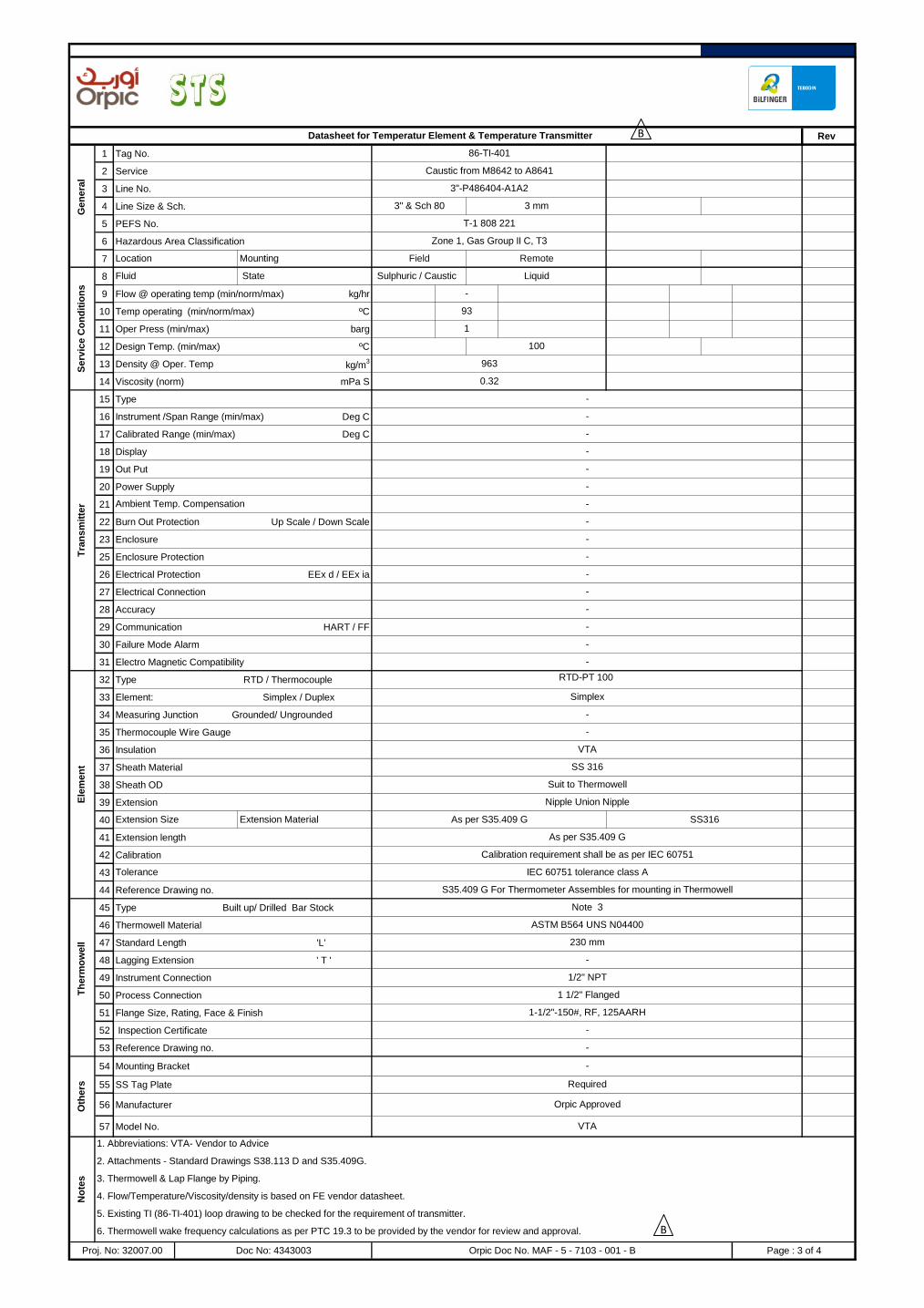
Rev
1 Tag No.
2 Service
3 Line No.
4 Line Size & Sch.
5 PEFS No.
6 Hazardous Area Classification
7
8
9 Flow @ operating temp (min/norm/max) kg/hr
10 Temp operating (min/norm/max) ºC
11 Oper Press (min/max) barg
12 Design Temp. (min/max) ºC
13 Density @ Oper. Temp kg/m3
14 Viscosity (norm) mPa S
15 Type
16 Instrument /Span Range (min/max) Deg C
17 Calibrated Range (min/max) Deg C
18 Display
19 Out Put
20 Power Supply
21
22 Burn Out Protection Up Scale / Down Scale
23 Enclosure
25 Enclosure Protection
26 Electrical Protection EEx d / EEx ia
27 Electrical Connection
28 Accuracy
29 Communication HART / FF
30 Failure Mode Alarm
31 Electro Magnetic Compatibility
32 Type RTD / Thermocouple
33 Element: Simplex / Duplex
34 Measuring Junction Grounded/ Ungrounded
35 Thermocouple Wire Gauge
36 Insulation
37 Sheath Material
38 Sheath OD
39 Extension
40
41 Extension length
42 Calibration
43
44 Reference Drawing no.
45 Type Built up/ Drilled Bar Stock
46 Thermowell Material
47 Standard Length 'L'
48 Lagging Extension ' T '
49 Instrument Connection
50 Process Connection
51 Flange Size, Rating, Face & Finish
52 Inspection Certificate
53 Reference Drawing no.
54 Mounting Bracket
55 SS Tag Plate
56 Manufacturer
57 Model No.
5. Existing TI (86-TI-401) loop drawing to be checked for the requirement of transmitter.
Datasheet for Temperatur Element & Temperature Transmitter
Gen
era
l
86-TI-401
Caustic from M8642 to A8641
3"-P486404-A1A2
Location Mounting Field Remote
T-1 808 221
Zone 1, Gas Group II C, T3
-
Serv
ice
Co
nd
itio
ns
Fluid State Sulphuric / Caustic Liquid
93
100
963
1
-
-
0.32
Tra
nsm
itte
r
-
-
-
-
-
-
Ambient Temp. Compensation
-
-
-
-
-
Orpic Approved
VTA
As per S35.409 G
Calibration requirement shall be as per IEC 60751
Tolerance IEC 60751 tolerance class A
S35.409 G For Thermometer Assembles for mounting in Thermowell
-
-
-
-
Ele
men
t
VTA
SS 316
Suit to Thermowell
Nipple Union Nipple
Extension Size Extension Material As per S35.409 G SS316
RTD-PT 100
Simplex
-
-
Proj. No: 32007.00 Doc No: 4343003 Orpic Doc No. MAF - 5 - 7103 - 001 - B Page : 3 of 4
3" & Sch 80 3 mm
No
tes
1. Abbreviations: VTA- Vendor to Advice
2. Attachments - Standard Drawings S38.113 D and S35.409G.
3. Thermowell & Lap Flange by Piping.
4. Flow/Temperature/Viscosity/density is based on FE vendor datasheet.
6. Thermowell wake frequency calculations as per PTC 19.3 to be provided by the vendor for review and approval.
1/2" NPT
1 1/2" Flanged
1-1/2"-150#, RF, 125AARH
-
-
Oth
ers
-
Required
Th
erm
ow
ell
Note 3
ASTM B564 UNS N04400
230 mm
B
B

Rev
1 Tag No.
2 Service
3 Line No.
4 Line Size & Sch.
5 PEFS No.
6 Hazardous Area Classification
7
8
9 Flow @ operating temp (min/norm/max) kg/hr
10 Temp operating (min/norm/max) ºC
11 Oper Press (min/max) barg
12 Design Temp. (min/max) ºC
13 Density @ Oper. Temp kg/m3
14 Viscosity (norm) mPa S
15 Type
16 Instrument /Span Range (min/max) Deg C
17 Calibrated Range (min/max) Deg C
18 Display
19 Out Put
20 Power Supply
21
22 Burn Out Protection Up Scale / Down Scale
23 Enclosure
25 Enclosure Protection
26 Electrical Protection EEx d / EEx ia
27 Electrical Connection
28 Accuracy
29 Communication HART / FF
30 Failure Mode Alarm
31 Electro Magnetic Compatibility
32 Type RTD / Thermocouple
33 Element: Simplex / Duplex
34 Measuring Junction Grounded/ Ungrounded
35 Thermocouple Wire Gauge
36 Insulation
37 Sheath Material
38 Sheath OD
39 Extension
40
41 Extension length
42 Calibration
43
44 Reference Drawing no.
45 Type Built up/ Drilled Bar Stock
46 Thermowell Material
47 Standard Length 'L'
48 Lagging Extension ' T '
49 Instrument Connection
50 Process Connection
51 Flange Size, Rating, Face & Finish
52 Inspection Certificate
53 Reference Drawing no.
54 Mounting Bracket
55 SS Tag Plate
56 Manufacturer
57 Model No.
-
Oth
ers
-
Required
Orpic Approved
VTA
Proj. No: 32007.00 Doc No: 4343003 Orpic Doc No. MAF - 5 - 7103 - 001 - B Page : 4 of 4
No
tes
1. Abbreviations: VTA- Vendor to Advice
2. Attachments - Standard Drawings S38.113 D and S35.409G.
3. Thermowell & Lap Flange by Piping.
4. Flow/Temperature/Viscosity/density is based on FE vendor datasheet.
6. Thermowell wake frequency calculations as per PTC 19.3 to be provided by the vendor for review and approval.
5. Datasheet based on existing 86-TA-401 Loop Drawing.
As per S35.409 G
Calibration requirement shall be as per IEC 60751
Tolerance IEC 60751 tolerance class A
S35.409 G For Thermometer Assembles for mounting in Thermowell
Th
erm
ow
ell
Note 3
ASTM B564 UNS N04400
230 mm
-
Ele
me
nt
1/2" NPT
1 1/2" Flanged
1-1/2"-150#, RF, 125AARH
-
SS 316
Suit to Thermowell
Nipple Union Nipple
Extension Size Extension Material As per S35.409 G SS316
-
-
-
-
RTD-PT 100
Simplex
-
-
VTA
-
-
-
-
0.32
Tra
ns
mit
ter
-
-
-
-
-
-
Ambient Temp. Compensation
1
-
-
-
Se
rvic
e C
on
dit
ion
s
Fluid State Sulphuric / Caustic Liquid
93
100
963
Location Mounting Field Remote
3" & Sch 80 3 mm
T-1 808 221
Zone 1, Gas Group II C, T3
Datasheet for Temperatur Element & Temperature Transmitter
Ge
ne
ral
86-TA-401
Caustic from M8642 to A8641
3"-P486404-A1A2
B
B

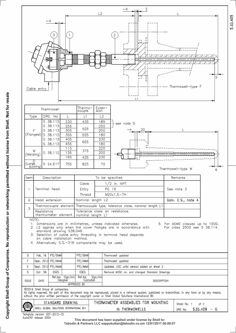
PROJECT: DD for Waste Water System Improvement
ISSUED FOR REVIEW
T & P Doc. No. : 4343004 CLIENT DOC. NO.
MAF - 5 - 7104 - 001 - B
ORPIC APPROVAL
LOCATION : MAF Refinery
AREA : SEWER FLUSHING UNIT
UNIT No. : 8640
T & P Proj No. : 32007.00
ISSUED FOR TENDER
REV DATE PREP'D CHK'D APPD DESCRIPTIONPROJ. ENGR. SIGN
A 23-01-17 SAP SVG SVG
B 31-01-17 SAP SVG SVG
DATASHEET FOR
TEMPERATURE GAUGE
DD for Waste Water System Improvement
Page 1 of 3
52980508
SAKET - SVG
52980508
Suraj - SAP
52980508
SAKET - SVG
52980508
C2 - Tender document
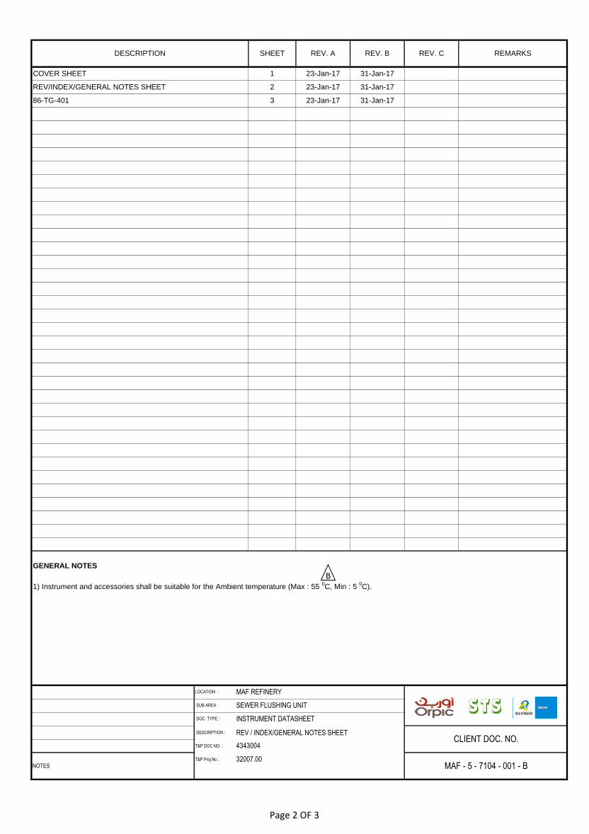
DESCRIPTION : REV / INDEX/GENERAL NOTES SHEET
T&P DOC NO. :
T&P Proj No :
REMARKS
CLIENT DOC. NO.
NOTES MAF - 5 - 7104 - 001 - B
LOCATION : MAF REFINERY
SUB AREA : SEWER FLUSHING UNIT
DOC. TYPE : INSTRUMENT DATASHEET
GENERAL NOTES
1) Instrument and accessories shall be suitable for the Ambient temperature (Max : 55 0C, Min : 5
0C).
3 23-Jan-17 31-Jan-17
COVER SHEET 1 23-Jan-17 31-Jan-17
DESCRIPTION SHEET REV. A REV. B REV. C
REV/INDEX/GENERAL NOTES SHEET 2 23-Jan-17 31-Jan-17
86-TG-401
4343004
32007.00
B
Page 2 OF 3
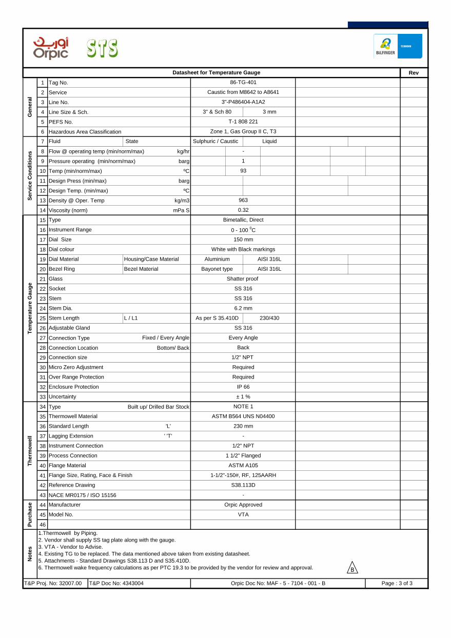
Rev
1 Tag No.
2 Service
3 Line No.
4 Line Size & Sch.
5 PEFS No.
6 Hazardous Area Classification
7
8 Flow @ operating temp (min/norm/max) kg/hr
9 Pressure operating (min/norm/max) barg
10 Temp (min/norm/max) ºC
11 Design Press (min/max) barg
12 Design Temp. (min/max) ºC
13 Density @ Oper. Temp kg/m3
14 Viscosity (norm) mPa S
15
16
17
18
19
20
21
22
23
24
25
26
27 Connection Type
28 Connection Location Bottom/ Back
29
30
31
32
33
34 Type Built up/ Drilled Bar Stock
35
36
37
38
39
40
41
42
43 NACE MR0175 / ISO 15156
44
45
46
T-1 808 221
Zone 1, Gas Group II C, T3
Datasheet for Temperature Gauge
Gen
era
l
86-TG-401
Caustic from M8642 to A8641
3"-P486404-A1A2
3" & Sch 80 3 mm
-
Serv
ice C
on
dit
ion
s
Fluid State Sulphuric / Caustic Liquid
1
93
963
0.32
Tem
pera
ture
Gau
ge
Type Bimetallic, Direct
Instrument Range 0 - 100 0C
Dial Material Housing/Case Material Aluminium AISI 316L
Dial Size 150 mm
Dial colour White with Black markings
Glass Shatter proof
Socket SS 316
Bezel Ring Bezel Material Bayonet type AISI 316L
Stem Length L / L1 As per S 35.410D 230/430
Every Angle
Back
Fixed / Every Angle
Adjustable Gland SS 316
Stem SS 316
Stem Dia. 6.2 mm
-
Uncertainty ± 1 %
ASTM A105
Flange Size, Rating, Face & Finish
Connection size 1/2" NPT
Micro Zero Adjustment Required
Over Range Protection Required
Enclosure Protection IP 66
ASTM B564 UNS N04400
Standard Length 'L' 230 mm
T&P Proj. No: 32007.00 T&P Doc No: 4343004 Orpic Doc No: MAF - 5 - 7104 - 001 - B Page : 3 of 3
VTA
No
tes
1.Thermowell by Piping.
2. Vendor shall supply SS tag plate along with the gauge.
3. VTA - Vendor to Advise.
4. Existing TG to be replaced. The data mentioned above taken from existing datasheet.
5. Attachments - Standard Drawings S38.113 D and S35.410D.
6. Thermowell wake frequency calculations as per PTC 19.3 to be provided by the vendor for review and approval.
Pu
rch
ase Manufacturer Orpic Approved
Model No.
Flange Material
1-1/2"-150#, RF, 125AARH
Instrument Connection 1/2" NPT
Process Connection 1 1/2" Flanged
Reference Drawing S38.113D
-
Th
erm
ow
ell
NOTE 1
Thermowell Material
Lagging Extension ' 'T'
B
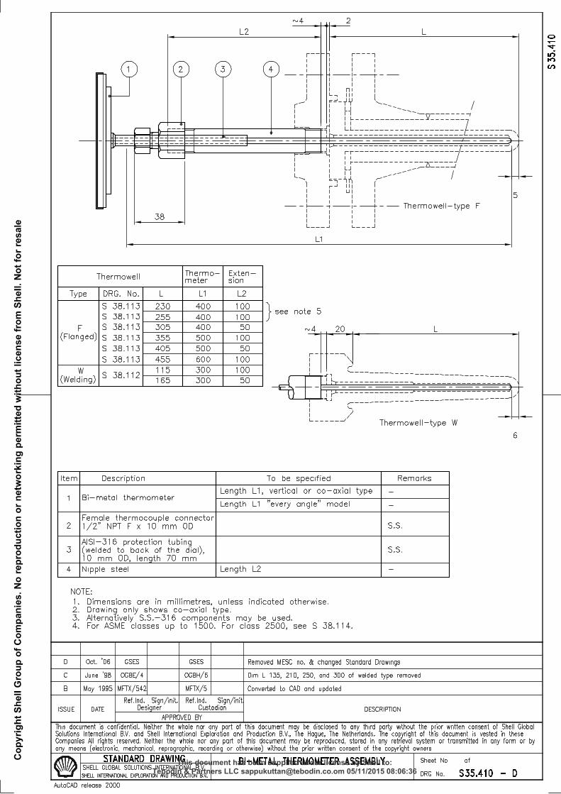

PROJECT: DD for Waste Water System Improvement
DATASHEET FOR
pH Analyser
DD for Waste Water System Improvement
B 31-01-17 SAP SVG SVG ISSUED FOR TENDER
REV DATE PREP'D CHK'D APPD DESCRIPTIONPROJ. ENGR. SIGN
A 23-01-17 SAP SVG SVG ISSUED FOR REVIEW
T & P Doc. No. : 4343005 CLIENT DOC. NO.
MAF - 5 - 7105 - 001 - B
ORPIC APPROVAL
LOCATION : MAF Refinery
AREA : SEWER FLUSHING UNIT
UNIT No. : 8640
T & P Proj No. : 32007.00
Page 1 of 3
52980508
SAKET - SVG
52980508
Suraj - SAP
52980508
SAKET - SVG
52980508
C2 - Tender document

DESCRIPTION : REV / INDEX/GENERAL NOTES SHEET
T&P DOC NO. :
T&P Proj No :
4343005
32007.00
COVER SHEET 1 23-Jan-17 31-Jan-17
DESCRIPTION SHEET REV. A REV. B REV. C
REV/INDEX/GENERAL NOTES SHEET 2 23-Jan-17 31-Jan-17
86-QA-401 / 86-QA-411 3 23-Jan-17 31-Jan-17
CLIENT DOC. NO.
NOTES MAF - 5 - 7105 - 001 - B
LOCATION : MAF REFINERY
SUB AREA : SEWER FLUSHING UNIT
DOC. TYPE : INSTRUMENT DATASHEET
GENERAL NOTES
1) Instrument and accessories shall be suitable for the Ambient temperature (Max : 55 0C, Min : 5
0C).
REMARKS
B
Page 2 OF 3

Rev
1 Tag No.
2 Service
3 Line No.
4 Line Size & Sch.
5 PEFS No.
6 Hazardous Area Classification
7
8
9 Flow @ operating temp (min/norm/max) m3/hr
10 Pressure operating (min/norm/max) barg
11 Temp (min/norm/max) ºC
12 Design Press (min/max) barg
13 Design Temp. (min/max) ºC
14 Density @ Oper. Temp kg/m3
15 Viscosity (norm) mPa S
16 pH Value Nor/ Max
17 pH measuring range
18
19
20
21 Electrolyte
22 Liquid Junction
23 Automatic Temperature Compensation
24 Holder Type Immersion / Insertion /Flow Through
25 Holder Material
26 Process Connection
27 Sensor Connection
28
29
30 Type
31 Display
32 Out Put
33 Power Supply
34 Enclosure
35 Enclosure Protection
36 Electrical Protection
37 Accuracy
38 Communication HART / FF
39 Power Consumption
40
41
42
43
44
45
46
47
48 Manufacturer
49 Model No.
50
Ex ib
± 1% / VTA
HART
Tra
ns
mit
ter
SH
S
Sample Handling System (SHS)
Sample Conditioning Unit
Required
Required
4 - 20 mA HART, Loop Powered
Required
Required
3" & sch 80 3" & sch 80
T-1-880-221-1-B T-1-880-221-1-B
Zone 1, Gr II B, T4 Zone 1, Gr II B, T4
Liquid
24 V DC
SS 316 SS 316
IP 66 IP 66
Ex ib
2 Wire, Smart 2 Wire, Smart
LCD LCD
24 V DC
4 - 20 mA HART, Loop Powered
pH ANALYSER
Ge
ne
ral
86-QA-401 86-QA-411
Caustic from M8642 to Spent Caustic
Neutralized skid
Neutralized water from Spent Caustic
Neutralized Skid to A8641
3"-P486404-A1A2 3"-P486404-A1A2
Se
rvic
e c
on
dit
ion
Fluid State Sulphuric / Caustic Liquid Neutralized Spent
Caustic
- 93 - -
- 10
963 (Hold1)
- 10 30
- -
93 (Hold1) -
7 7
Stream Composition 10% - 68% Neutralized form
- 1.5(Hold1) -
30
VTA VTA
0.32 0.32 (Hold1)
10 ~ 13 6 ~ 9
1-14 1-14
100 100
963
VTA VTA
VTA VTA
VTA VTA
VTA VTA
Required Required
Required
± 1% / VTA
HART
VTA VTA
Se
ns
or
Type Combination electrode Combination electrode
Body VTA VTA
Measuring Electrode Reference Electrode
Required Required
Cleaning system Automatic Automatic
VTA VTA
Sample in /out 1/2" NPT (F) Sample in /out 1/2" NPT (F)
Orpic Doc No: MAF - 5 - 7105 - 001 - B
1.5
No
tes
Holds
1 : Vendor to confirm.
Notes:
1. The system shall include a sensor, transmitter and sampling system. Sampling system shall consists of valves, Y-type strainer, pressure
gauge and glass flowmeter all mounted on 316SS Board (plate). Sample cooler may be required in accordance with Vendor recommendation.
2. Vendor shall specify the suitable sample take off and sample drain connection with schematic diagram .
3. Vendor to provide suitable sample handling system for extraction of sample & return.
4. Vendor to clearly state the requirement of the Utilities.
5. The Vendor shall provide the necessary calibration materials such as powdered buffers and concentrated buffer solution.
Page : 3 of 3T&P Proj. No: 32007.00 T&P Doc No: 4343005
Buffer solution VTA VTA
Cable VTA
Pu
rch
as
e Orpic Approved Orpic Approved
VTA VTA
VTA
Op
tio
ns
Mounting Bracket for Transmitter
SS Tag Plate Required
B
B
B


![REQUEST FOR QUOTATION (RFQ) (Service) - UNDP Request For Quotation... · REQUEST FOR QUOTATION (RFQ) (Service) NAME & ADDRESS OF FIRM ... ☐SEA ☐OTHER [pls. specify] ... ☒ Certificate](https://static.fdocuments.in/doc/165x107/5b74b8637f8b9aa01f8c7274/request-for-quotation-rfq-service-request-for-quotation-request-for.jpg)