
Request for Proposals for - MHPA · Request for Proposals for 5.0 MWp Solar ... 2.1.6 Full module...
55
1 Request for Proposals for 5.0 MWp Solar Photovoltaic Power Plant At Liddeston Ridge For Port of Milford Haven January 2013
-
Upload
nguyencong -
Category
Documents
-
view
220 -
download
1
Transcript of Request for Proposals for - MHPA · Request for Proposals for 5.0 MWp Solar ... 2.1.6 Full module...

1
Request for Proposals for
5.0 MWp Solar Photovoltaic Power Plant
At Liddeston Ridge
For Port of Milford Haven
January 2013

2
Table of Contents
1) Instructions to Bidders.
2) Details of Deliverables from Bidders.
3) Technical Specification of Project - Provided by Customer.
4) Information on Tender evaluation.
5) General and Specific Conditions of Contract.

3
Definitions CDM Regulations means the Construction (Design and Management) Regulations 2007(S.I.2007/320), the associated Approved Code of Practice entitled, “Managing Health and Safety in Construction” (published in2007) including without limitation Chapter 2 thereof and any other relevant guidance issued from time to time by the UK Health and Safety Executive.
PVS means power plant & associated infrastructure
MHPA means Milford Haven Port Authority
Customer means Milford Haven Port Authority
EPC means Engineering Procurement and Construction Contractor
Site means Liddeston Ridge, Milford Haven, Pembrokeshire, Wales, UK, SA73 2BS.
PWI means Pure Wafer International.

4
1, Instruction to Bidders
Project Overview
Milford Haven Port Authority (MHPA) are seeking competitive proposals for the
complete development , construction and start-up of a single 5.0MWp utility scale
solar photovoltaic energy power plant (PVS) at Liddeston Ridge , Milford Haven,
Pembrokeshire, Wales, UK, SA73 2BS.
The PVS is to be designed, engineered and constructed in accordance with Milford
Haven Port Authority’s requirements as defined in this RFP and the EPC agreement.
The PV system shall be connected to a 33KV metering circuit breaker installed by
the local distributed network operator (Western Power Distribution) connected to a
tee in the overhead cable line between the Steynton and Milford Haven 33KV/11KV
substation that runs through the site at Liddeston Ridge (as described in the
connection agreement, see Appendix A).
The primary role of the contractor is to execute a Design-Build Agreement, provide
turnkey planning, design, engineering, labour, materials, delivery, installation, and
commissioning of a cost-effective and energy efficient solar PV system together with
associated infrastructure, to maximise the use of the solar resource at Liddeston
Ridge.
The targeted size of the solar installation is 5.0MWp however consideration will be
given for proposals that maximise the return on investment of the solar resource at
the site. The project is to be completed within 3-months from the issuance of the
Notice to Proceed (NTP) instruction.
The successful EPC shall provide qualified personnel for services, including—but not
limited to the following tasks:
1. Turnkey planning, design, engineering, labour, materials, delivery, installation,
monitoring and commissioning of a cost-effective and energy efficient solar PV
system.
2. Warranties & Guarantees.
3. Provision of Bank Guarantees and Insurances.
4. O & M support for the site.
5. A full & comprehensive insurance wrapper for the complete EPC Contract.

5
Milford Haven Port Authority has engaged Pure Wafer International (PWI) in a
consultancy capacity to manage the EPC procurement process on their behalf.
MHPA have also obtained the necessary planning approval for the PVS from
Pembrokeshire County Council and also have a connection agreement with Western
Power Distribution for connection to the 33KV line at the site.
General Instructions
If you intend to quote for the Solar Photovoltaic System, please read through the
following instructions carefully and prepare your quotation accordingly.
Your organisation must bear all costs associated with the bidding process itself,
including the site visit, attendance at clarification meetings and any visit to your
organisation’s premises if requested.
If MHPA need to issue any additions or clarification to these documents during the
bidding period, they will only do so in writing (usually by email) to all suppliers.
Any questions, queries or clarifications from suppliers should be directed to PWI.
Please e-mail; [email protected]
Suppliers will be invited to arrange site visits to the sites between 29th January 2013
and 22nd February 2013.
For information regarding the RFP and to arrange a site visit;
Pure Wafer International
Millbrook Drive,
Swansea Vale,
Swansea.
SA70AB
Contact Name: Mr Tony Powell
E-mail: [email protected]

6
RFP Schedule
Date Event
25/01/2013 to 1/2/2013 RFP & Draft Contract issued to suppliers
21st Jan to 22nd February 2013 Pre-Bid meetings and site visits
12-Feb to 24th Feb-2013 Tender Review and formulation and submission of post tender questions to bidders
26th Feb 2013 Questions back from bidders and selection of preferred bidder
28/02/2013 Selection of Preferred supplier
08/03/2013 Contract Agreed in Principle
14/03/2013 MHPA Board Approval & Formal Offer
All information in this RFP document set shall be treated as confidential.
Please submit one hard copy of your quotation, plus one electronic copy via email to
You may complete your responses on a separate document providing the quotation
is cross referenced to the section and paragraph numbers of this RFP.
All sections must be responded to even if simply “Understood” or “Agreed”.
Where any external reference material, such as brochures, specifications and system
descriptions, is used to support your quotation, any statements within the reference
material which may allow change to obligations or reduce liability, such as
"specifications subject to change without notice", or other disclaimers, will be
regarded as void and shall not form part of the purchase order or contract in the
event that the quotation is accepted.
All pricing should be stated in pounds sterling exclusive of VAT.
Quotations shall remain open for an initial acceptance for a minimum of 90 calendar
days, although the Port Authority may ask you to extend the period of validity.
Where bidders cannot meet the required specifications detailed in this RFP,
alternative proposals should be provided by the EPC. The alternative proposals will
be reviewed on their merits during the Vender selection process.
7
2. Deliverables from Bidders
Each bidder is required to provide the following information in response to this RFP;
The information must be provided along with a covering letter, the covering letter
must include the names, addresses and signatures of a representative or
representatives having authority to contractually commit to the offer provided in
the proposal.
2.1 Solar Plant Design
You are required to provide the principle design parameters and drawings
forming the basis of your proposals. As a minimum, the following detailed
information must be provided in accordance to the specifications detailed in
Section 4.0.
Part of the design process consideration must be made to the commitments
made by MHPA during the planning approval process. These include minimising
the impact of noise when using plant & equipment, colour coding of fences, poles
and transformer housings to minimise the visual and landscape impact of the
PVS.
2.1.1. Overall system schematic diagram. 2.1.2. Single line electrical diagram. 2.1.3. Structural design drawings and material specifications. 2.1.4. Structural design calculations (including wind loading). 2.1.5. PV panels and structural installation drawings, detailing string layouts,
array cross sections and indicative row spacings.
2.1.6 Full module layout drawing detailing the total foot print area required for the power plant.
2.1.7 Drawings, photographs and descriptions of all sub-station and
transformer housings.
2.1.8 Full electrical design drawings detailing all voltages, inputs and outputs on system DC and AC sides as well as DC and AC cable sizing and layout.
2.1.9. PV array and inverter design calculations. 2.1.10. DC and AC electrical BoS design calculations.

8
2.1.11. Earthing system diagrams 2.1.12. Detailed B of Q, / B of M and specifications, inclusive of supplier names, Model No’s and contact details. 2.1.13. Plant power performance ratio calculations and guarantees 2.1.14. Plant energy performance ratio calculations and guarantees. 2.1.15. Plant performance simulations. 2.1.16. Estimated yearly degradation of PV module power output over a 25 year
period. 2.1.17. Typical or projected degradation rates for the total system over a 25-year
period if available.
2.1.18. Estimated plant energy generation in the first year up to the 25th year measured at system’s the delivery point at WPD’s 33kV connection point.
2.1.19. Details of Corrosion Prevention design considerations. 2.1.20. Details of the works required for the Grid connection to WPD’s 33kV exit
point at the site including all contestable works in accordance with the connection offer attached in Appendix A.
2.1.21. Calculations on the total contribution to fault level from the system at the
33kV Exit point.
2.1.22. Details of safety devices, features, measures taken for periodic cleaning and access of the PVS.
2.1.23. Typical useful life of significant plant components, include but not limited
to the PV array and inverters. 2.1.24 All other information you consider relevant to your bid.
2.2 System Technical Description
2.2.1 Description of the PV plant.
2.2.1.1. The EPC must provide a description of the Benefits specific to the type of system proposed and any Product enhancements you would make available, if any.
9
2.2.1.2. The EPC must provide a technical description of the technology that they
propose to use, including detailed datasheets and conformance to
standards, for all equipment.
1) PV Modules.
2) Inverters.
3) Mounting frames.
4) Balance of system components.
5) Offgem approved Generation meters used on the system.
6) Transformers.
7) G59 protection equipment.
8) Earthing system including a description of the materials used.
2.3 Financial Proposal
2.3.1 Provide a binding complete fixed price cost proposal for a Turnkey EPC
proposal for construction of the solar power plant.
2.3.2 Provide details of the Project cost phasing highlighting the timing of key
costs occurring during the construction of the project.
2.3.3 Provide details of your payment terms and payment schedule relevant to
each critical point within the project, including procurement,
construction, and commissioning, final acceptance and performance
confirmation.
2.3.4 Provide details of the bankability of the proposed system, providing
confirmation of the bankability of the solar modules proposed for the
project as well as references from financial organisations that have
historically funded projects with a similar design and construction.
2.3.5 Describe your bonding capacity and costs to bond this project. The project
will require a payment bond and a performance bond according to the
requirements of the contract. Also include, from your bonding agent a
letter of intent to bond the project in the event of an award.
2.3.6 Provide your audited financial statements for 2011 and 2012. If audited
financial statements are unavailable, provide financial statements
certified by a reputable accounting firm as accurately presenting the

10
financial position of your company, in accordance with generally accepted
accounting principles.
2.3.7 Provide details of the annual O & M costs including insurance charges for
the plant.
2.3.8 Provide details of the annual O & M escalation per year for the first 25
years of operation of the power plant.
2.3.9 Provide details of the projected cost of replacement parts required to
keep the plant fully operational for the first 25 years of operation.
2.3.10 Contractors must demonstrate sufficient financial capabilities to perform
this scope of work.
2.3.11 Provide details of insurances in place to protect the Customer from risks
associated with the project.
2.3.12 Describe details of all penalties/ liquidated damages provided as
compensation for both project delays and poor performance of the
system.
2.3.13. Provide details of any additional financial support available with your
proposal e.g. PPA agreements.
2.4 Warranties and Performance Guarantees
2.4.1 Provide details of the Warranties and Guarantees provided for all system
components within your proposal.
2.4.2 Provide details and costs of any additional warranties offered as an option
for the project.
2.4.3 Provide details of your performance Guarantees for the system, also
provide a description of the method that will be used to verify the
contractual performance guarantees.
2.4.4 Describe details of your Mechanical completion, Provisional acceptance
and Final acceptance protocol and specifications for the system.
2.4.6 Provide details of the Customer’s obligations for compliance with
warranty requirements.
11
2.5 Insurances
2.5.1 The EPC is required to provide evidence that adequate levels of insurance
are provided for successful completion of this project including as a
minimum;
1) Public liability insurance - £10M.
2) Employer’s liability insurance - £5M.
3) Professional indemnity insurance - £10M.
4) Product liability insurance - £5M.
5) The respondent is required to provide evidence of this minimum level
of cover with their proposal.
2.5.2 Please provide full details of any claims in excess of £50,000 made under
your company/organisation’s insurance policies within the last 12
months.
2.5.3 Provide details of all insurance wrappers provided, to support both
equipment warranties and performance guarantees.
2. 6 Building Control
2.6.1 The contractor will be responsible for obtaining building control approval
for the installation.
2.6.2 Include a description of the EPC’s understanding of the laws and
regulations that are pertinent to the site and describe how the EPC
intends to comply with these laws and regulations.
2.7 Key Project risks
2.7.1 The EPC should identify all risks that may impact the project and provide
mitigation strategies to address these risks.

12
2.8: Description of Approach to Conducting the Work
2.8.1 Provide a detailed description of your approach to conducting the work described in the Scope of Services (Section 3), including a description of the roles of key employees who will work on this project. 2.8.2 The Contractor must take into account aesthetic and structural
considerations associated with the installation; provide a brief discussion about how this issue is factored into the overall design process.
2.8.3 Describe the proposed project approach that will be taken, how the
agreed design will be achieved, and the process required to execute the building and commissioning of the design.
2.8.4 Describe the approach to be taken with all agencies and parties that will
be involved.
2.9 Implementation / Milestone Schedule
2.9.1 Propose an implementation schedule; at a minimum including, but not limited to the following milestones listed below. Please note Task Completion dates should be referenced to the Contractor’s receipt of the Notice to Proceed.
Also include all principal tasks and approvals and permits required including;
1) Receipt of Notice to Proceed.
2) Completion of Final design and obtain agreement with customer and WPD.
3) Obtain required approvals and permits.
4) Obtain interconnection approval from WPD.
5) Delivery of PV arrays, Inverters and BOS components.
6) Completion of LV installation.
7) Completion of HV installation.
8) Completion of functional testing.
9) Completion of G59 witness testing and energisation of the system.
10) Completion of provisional acceptance test.

13
11) Conduct on-site training.
12) Delivery of O & M Manuals and all Health & Safety Handover documentation,
which will also include ‘as-built drawings’.
2.7 EPC Contractor Information:
2.7.1 Background and Qualifications
2.7.1 Each Bidder must include the following information regarding the
Contractor and team;
1) Name of Prime Contractor and other team members, including major Sub Contractor(s) and Contractor(s).
2) Roles and responsibilities of, and relationship between the team members, including an organisation chart to illustrate the team structure. 3) A Brief description of the Prime Contractor, including a summary of the company’s background. 4) Provide a C.V of each team member, detailing background and experience, which demonstrates the team member’s qualifications and capability to perform the assigned responsibilities, including technical resources and access to equipment.
5) Identify the key individual who will manage the project and interface with the key stakeholders of the project. Also identify the key individual(s), who will be responsible for all H & S matters, during mobilisation and the construction phase, detailing their experience and relevant H & S Qualifications.
6) Provide examples of past projects on which the team members have worked together. 7) Provide details of the Contractors Licenses classification and license number which will be used to perform this work.
2.7.2 Prime Contractor Information
Include the following for the Prime Contractor:
1) Total capacity in Megawatts, of PV systems placed in commercial operation to date and experience of commercial projects >1MW.

14
2) Provide some brief descriptions of recent PV system installations, including the specific manufacturer and model type of the equipment used, indicating if projects were ‘Turnkey’ in nature.
3) Indicate whether the Prime Contractor or its officers or principals
have been party to any lawsuit involving the performance of any equipment it has installed, including environmental litigation, and provide a summary of the issues and status of the lawsuits.
4) Indicate whether or not you have been late on a project within the
last three years due to inexcusable delays, and if you have had to pay liquidated damages for lateness or performance.
2.7.2 Prime Contractor’s References
Provide if possible a minimum of three (3) references for Turnkey PV installations completed. Each reference must include, but not be limited to the following information:
1) Project Capacity (kWp).
2) Total Cost (£).
3) Operational and Maintenance cost (/kWh), if available.
4) Year installation was completed.
5) Customer Name and Address.
6) Contact Name, Title, Contact Number, and e-mail address.
2.8: Operation and Maintenance (O &M) Requirements
2.8.1 Provide full details of the O & M requirements for the installation.
2.8.2 Provide details of training provided to the Customers O & M
Personnel.
2.8.3 Provide a list of spare parts provided with the system together
with a recommended list of spare parts required to support the O
& M program.

15
2.9 Description of Power Plant Performance Monitoring
2.9.1 Provide a description of the monitoring system proposed for this project,
including but not limited to, the following information;
1) Equipment requirements.
2) Data output.
3) Alarm system.
4) Emergency Llighting.
5) CCTV system to MHPA Specification.
6) Security fencing, gates and locks.
7) Maintenance requirements.
8) Remote Interface requirements.
9) Describe how the information needed, as described in the Section 3 of this RFP, will be provided with these systems.
10) Describe how individual or groups of panels and other system components will be easily accessed to detect and isolate problems.
2.10 Certification of Products
2.10.1 Provide copies of all relevant certificates regarding critical
components including but not limited to:
1) IEC 61215, IEC 61730 and UL1703 certification of the PV modules.
2) G59/2, IEC62116 and UL1741certification of Inverters.
3) IP rating of electrical equipment.
4) MC (or equivalent) rating of PV DC connectors.

16
2.11 On-site Facilities
2.11.1 There are some facilities on the site that will be provided by Milford
Haven Port Authority, these will be explained during the site visit, in
addition, please provide as part of your proposal;
1) A site project office for project management/site management team with provision for electricity, lighting, telephone/fax, etc.
2) Welfare facilities for the construction team.
3) Storage and security facilities for all materials required for the construction of the plant.
2.12 Reporting to Customer / Stakeholders
2.12 Briefly describe how you will communicate and report to the
following stakeholders:
2.12.1 Liaison with Building Control and Planning.
2.12.2 Liaison with the CDM compliance officer of MHPA.
2.12.3 Liaison with the Distributed Network Operator.
2.13 Waste Management
2.13.1 Provide a description of how you plan to manage waste at the
construction site.
2.14 Logistics and Site Control
12.14.1 Provide a description of how you will deliver goods and services
to the site in compliance with the traffic management plan for the site.
12.14.2 Each proposal shall clearly indicate that the EPC has considered
and included all factors relating to the site in its proposal, including with
respect to its access, site preparation, interconnection and site related
costs. Particular attention is drawn to the close proximity of the site to a
residential area and also the coast and this must be considered in the
proposal.
2.15 Exclusions

17
2.15.1 The EPC is required to complete a ‘Turnkey’ solution for the construction
of the PVS. A complete list of exclusions must be provided with your proposal
highlighting what you require from MHPA as the customer to ensure a successful
completion of the PVS. Items such as permits, approvals, preparation works,
access arrangements, communication link, metering, information and
documentation. It will be assumed that all items not highlighted or included in
the list of exclusions will be the responsibility of the EPC.
3.0 Technical Description of System and Services
3.1 EPC Integrator Scope of Work
3.1.1 The EPC’s primary responsibilities are to undertake and perform all the works and services required for the planning and construction of the complete Photovoltaic System. These primary obligations include;
3.1.1.1 Drawing up the final and working plans for the construction of the PVS.
3.1.1.2 Detailed electrical, mechanical, computer and civil design and engineering of the PVS.
3.1.1.3 The selection, procurement, transport and delivery of all materials required in the construction of the PVS.
3.1.1.4 Constructing and equipping the Photovoltaic power plant, including Managing, coordinating and supervising the construction project.
3.1.1.5 Implementation of all works required to connect the PVS to the electrical grid and co-ordinating (but not including) the works commissioned by MHPA from the Distribution Network Operator .This includes procurement and implementation of all works identified as contestable by the DNO in the connection offer.
3.1.1.6 Carrying out on behalf of the Customer all inspections, acceptances, tests, certificates and measurements, which are required by authorities and/or the DNO.
3.1.1.7 Provision of a data monitoring system to monitor the performance of the plant as well as the environmental conditions affecting the performance of the Plant. 3.1.1.8 Providing assistance to the Purchaser in respect of the conclusion of a contract for the provision of a data communication connection regarding the remote data monitoring system (such contract to be concluded between the Purchaser and the telecommunications service provider).
18
3.1.1.9 Carry out Operation, Maintenance and Monitoring of the plant for the first 5Years. 3.1.1.10 Ensure that the PVS is constructed in compliance with Health and Safety regulations and Local Building Control. 3.1.1.11 Liaison with MHPA for any civil, landscape, environmental and health and safety issues.
3.1.1.12The EPC is responsible for all permitting, other than permits and
approvals needed by MHPA to construct the MHPA’s proportion of any
interconnection facilities. The EPC is solely responsible for understanding and
acquiring all necessary additional permits in connection with the PVS.
3.1.2 Other EPC obligations include (beginning with the construction phase and ending with the formal acceptance of the PVS):
3.1.2.1 Providing additional site facilities required on the Construction Site.
3.1.2.2 Transporting to and from the Construction Site and storing and securing on site all the tools and equipment required in the construction of the PVS.
3.1.2.3 Providing facilities for adequately supplying the Construction Site with water, electricity and heating as required in the construction of the PVS.
3.1.2.4 Keeping the Construction Site in a clean and orderly condition taking into account the prevailing weather conditions.
3.1.2.5 Liaising with the Distribution Network Operator regarding grid connection of the PVS.
3.1.2.6 Testing and Acceptance of components and sub‐assemblies on site.
3.1.2.7 Installation, testing and commissioning of the plant.
3.1.2.8 Liaison with MHPA and WPD for the power evacuation plan and power plant certification, approval and acceptance.
3.1.2.9 The provision of plant technical manuals and user O & M manuals for the completed PVS.
3.1.2.10 Provision of all ‘as built’ drawings for the PVS including: PV array site plans, electrical line diagrams, structural installation drawings, wiring and Earthing diagrams, Transformer and HV switch enclosure installation drawings, drawings of all underground trenches foundations and facilities.
3.1.2.11 Provision of in‐house training in operation, testing, monitoring and maintenance of the plant.

19
3.1.2.12 Ensure compliance with all the regulatory and quality standards. 3.1.2.13 Provision of any information required for the customer to discharge their duties and obligations in accordance with their planning application, including the traffic management plan, pollution response plan and final design of the site including lighting, fencing and poles etc.
3.2 General System Description and Specification
3.2.1 It is proposed that a grid tied solar PV power plant up to a maximum capacity of 5.0MWp is to be constructed on the site.
3.2.2 The PVS shall feed AC power to the 33kV distribution grid at the connection point provided by WPD.
3.2.3 The PVS shall consist of PV arrays, fixed PV array support structures, String/Array combiner boxes, DC cabling, DC distribution boxes, Inverters, AC cabling, AC distribution boxes, AC energy meters, transformers, controls, HV cables, Earthing conductors and protection equipment.
3.2.4 The PV power plant shall monitor the solar generated energy using plant AC energy Metering at the LV side of the LV/HV transformers via a remote monitoring facility.
3.2.5 The proposal should also include a solar radiation and environment monitoring system to be installed on the site. 3.2.6. The system should be designed to maximise the return on investment at
the site, it is expected that the annual power generation in the first year will be at
least 5000 MWhr.
3.2.7 The system should be designed not to exceed a power output of 5,25MVA at
the WPD 33kV connection point.
3.2.8 The operating life of the plant shall be minimum 25 years. 3.2.9 The degradation in power output of the plant shall be no more than 10% in the first 10 years of operation and no more than 20% after 25 years of operation. 3.2.10 The PVS must be designed with an availability of at least 98% over the lifetime of the plant. 3.2.11The specified operating temperature of the site is -40C to +35C. 3.2.12 The system should be designed to operate at the Liddeston Ridge site,
noting its close proximity to the coast.

20
3.2.13 The overall power performance ratio of the system shall exceed 70%. (Sum total of the system power losses shall not exceed 30%). This allows for elevated module temperature during afternoon hours, for global solar radiation in the Plane of Array (POA) of 1000 W/m2, a 5250kWp PV power plant AC output shall be a minimum of 3675 kW at any time during the day. Correction shall be applied based on available solar radiation. For example, for 800 W/m2 radiation, 5250kWp PV power plant shall produce min. of 2940 kW AC output.
3.2.14. The overall energy performance ratio of the system shall exceed 75%. (Sum total of the system energy losses shall not exceed 25%). For global solar insolation in the Plane of Array (POA) of 5 kWh/m2 (5 Peak Sun Hours) for the day, 5000kWp PV power plant AC energy output shall be minimum of 19687.5kWh for the day.
3.3 Detailed System Description
3.3.1 PV Array
3.3.1.1 The PV array shall consist of mono‐crystalline, multi‐crystalline or thin film PV modules, the EPC must justify the selected use of modules used in the design of the PVS.
3.3.1.2 The power rating of each individual PV module should be a minimum 160 watt peak at STC.
3.3.1.3 The rated maximum power rating of PV modules should have positive tolerance in range of 0 to +3% and the negative temperature coefficient of power for PV modules should be less than or equal to 0.45% per deg. C.
3.3.1.4 A suitable number of Solar PV modules shall be connected in series strings. A suitable number of series strings shall be connected in parallel to formulate a series‐parallel array.
3.3.1.5 The PV strings and array shall be designed to match the inverter input specification.
3.3.1.6 The Maximum DC output voltage of the array shall not exceed 700V.
3.3.1.7 The modules shall be provided with hermetically sealed junction boxes with provision of min of 3 by‐pass diodes. The junction box should have hinged, weatherproof lid with captive screws and cable gland entry points.
3.3.1.8. The front surface of the module shall consist of impact resistant, low iron and high transmission toughened glass.
3.3.1.9. The module frame shall be made of corrosion resistant material electrically compatible with the structural material used for mounting the modules.

21
3.3.1.10 All solar PV modules shall comply with either IEC 61215(Crystalline PV modules) or IEC61646 (for thin film modules) as well as certified to UL1703.
3.3.1.11The solar PV modules shall come complete with solar cable connectors
that meet international standards for module interconnection (MC4 or
equivalent).
3.3.1.12 A minimum performance warranty of 25 years shall be provided with
degradation in power output less than 20% over this 25 year period. The power
output degradation in the first 10 years must not exceed 10%.
3.3.1.13 The solar PV modules electrical characteristics including current-voltage
curves, and temperature coefficients of module power, voltage and current etc.,
shall be provided with the datasheets for the modules.
3.3.1.14 All relevant literature and technical information for the solar PV
modules must be provided. This specifically includes: Voc, Isc, and Wp at STC
conditions. The relationship between temperature and module output, I-V curves
for 500, 700, 800 and 1000 W/m2 solar input, physical size and weight and
details of the materials used in construction, particularly backing material and
encapsulation material.
3.3.1.15 All Flash test data for the solar PV modules shall be provided including
Vcc, Isc, Pmax, Vpm, Imp and fill factor etc.
3.3.1.16 A product warranty of a minimum of 10 years from the date of delivery
shall be provided. It shall warrant the PV modules supplied against any defects in
materials and workmanship under normal, application, installation, use and
service conditions.
3.3.1.17 The solar modules must be recognised as bankable to major financial
institutions. Modules should be classified as ‘Tier 1’ by Bloomberg new energy
finance. Selection of Tier 2 modules must be justified for their bankability within
the proposal.
3.3.2 Grid Tied Inverter(s)
3.3.2.1 The sine wave output of the inverters shall be suitable for connecting and synchronising to the 415V, 3 phase AC LV voltage side of the LV/HV transformers.
3.3.2.2 The inverter shall incorporate grid islanding protection, suitable DC/AC fuses/circuit breakers and voltage surge protection. Fuses used in the DC circuit must be DC rated.
22
3.3.2.3 The inverter shall have internal protection against any sustained faults and/or lightening in DC and mains AC grid circuits.
3.3.2.4 The inverters must be G59/2 compliant which automatically disconnect the solar PV supply from the grid when the AC output is outside the limits defined in Engineering Recommendations G59/2. Isolating transformers shall be installed on the AC side of the inverters to eliminate the possibility of the system injecting DC current into the grid. Reconnection shall occur locally at the location of the inverters.
3.3.2.5 The inverters must have at least a 10 year warranty Guarantee.
3.3.2.6 The inverter shall include adequate internal cooling arrangements (exhaust fan and ducting) for operation in a non‐AC environment.
3.3.2.7 If the inverters are to be located outside they must have an IP65 rating.
3.3.2.8 If the inverters are to be enclosed in cabinets, the inverter cabinets must be IP65 rated and the inverters must be compatible with the environment expected at the site. The cabinets shall be designed for operation with natural cooling as far as possible. If cooling by forced convection is required, at least two (2) numbers of ventilation fans each rated at 100% of the required capacity shall be provided. The ventilation fans shall be equipped with monitoring, control and alarm signals.
3.3.2.9 The maximum permissible DC input voltage to the inverters shall be 700V and the THD must be less than 4%.
3.3.2.10 The inverters shall provide display of Time, PV array DC voltage, current and power, AC output voltage and current (All 3 phases and lines), maximum AC power generated and Instantaneous Power (Active, Reactive and Apparent), Power Factor (All 3 phases and cumulative) and frequency. Remote monitoring of inverter parameters must be possible to connect to the PVS monitoring system. 3.3.2.11 The inverters provided shall have an efficiency of at least 94% at full
load operating condition.
3.3.2.12 The solar PV system shall have a lagging power factor greater than 0.9
when the output is greater than 50% of the rated inverter output power.
3.3.2.13 The inverters shall fully comply with the utility interface specifications
set forth in IEC 61727. The inverters shall also comply with IEC 61000-6
regulations on electromagnetic compatibility (EMC) emissions as well as IEC
61000-3 regulations on limits for harmonic current and voltage fluctuations
emissions.

23
3.3.2.14 The inverter system and all associated electrical components shall be
effectively linked to the main earthing system of the electrical distribution
network (permission to connect to this main earthing system must be agreed
with WPD prior to connecting).
3.3.2.15 The inverter system shall include DC ground-fault protection, which
must disable the solar PV module in the event of a short-circuit to ground on the
DC input of the inverter.
3.3.2.16 The inverter system shall be provided with a RED push button for
emergency switching off of the inverter system.
3.3.2.17 Independent of whether a multiple string inverter solution is provided
or a central inverter solution, data must be provided for all DC strings connected
to the inverters. The EPC must justify their choice of inverter design in their
proposal.
3.3 .3 System Earthing / Lightning Protection.
3.3.3.1 It is the EPC’s responsibility to ensure that the Installation has adequate
earth fault protection and no liability will be accepted by WPD if its earth
terminal or electrode is incorporated in power plants earthing system.
3.3.3.2 The EPC must commission an earthing study at the site which must be
provided to MHPA and WPD.
3.3.3.3 It is the responsibility of the EPC to provide all earthing arrangements at
the site that meet the specifications agreed by WPD and within the Engineering
specification EE SPEC:89/2.
3.3.3.4 The EPC must install a fixed earth grid and electrodes at the site. The EPC
must allow WPD to connect to this earthing system at no cost. The EPC must
obtain agreement from WPD on the design and construction of the Earthing
system prior to building the earthing system.
3.3.3.5 Any costs associated with making the generator site or WPD’s substation ‘cold’ or mitigating the effects of being ‘hot’ shall be borne by the customer.
3.3.3.6 The PV array, DC equipment, Inverters, AC equipment and distribution wiring shall be earthed as required.
3.3.3.7 Equipment grounding (Earthing) shall connect all non‐current carrying metal receptacles, electrical boxes, appliance frames, chassis and PV panel mounting structures in one long run. The grounding wire should not be switched, fused or interrupted.

24
3.3.3.8. The complete earthing system shall be electrically connected to provide return to earth from all equipment independent of mechanical connection.
3.3.3.9 The equipment grounding wire shall be connected to one grounding electrode of each PV power plant.
3.3.3.10 A separate grounding electrode shall be installed using earth pit per
power plant. Test point shall be provided for each earth pit.
3.3.3.11 An earth bus and a test point shall be provided inside each transformer and HV switch housing.
3.3.4 Balance of System
3.3.4.1 String/Array combiner boxes shall incorporate DC string circuit breakers, DC array disconnect switches, lightening and over voltage protectors using screw type terminal strips and strain‐relief cable glands. The SPD’s shall be rated in accordance with IEC 61643-12.
3.3.4.2. All DC and AC cables shall be terminated using suitable crimped cable lugs/sockets and screw type terminal strips. No soldered cable termination shall be accepted.
3.3.4.3 All wiring must be certified in accordance with the 17th edition IEE wiring regulations (BS7671).
3.3.4.4 Only terminal cable joints shall be accepted. No cable joint to join two cable ends shall be accepted.
3.3.4.5 Suitable Ground Fault Detector Interrupters (GFDI’s) shall be incorporated either within the inverter or within the array combiner box.
3.3.4.6 String/Array combiner boxes shall be secured onto metal support structures.
3.3.4.7 Conduits/ cable trays shall be provided for all DC cabling, these should be adequately secured to the PV array mounting structures.
3.3.4.8 The DC and AC cable type shall be PVC/XLPE insulated, suitably armoured, 1000V grade multi‐stranded copper conductor. Appropriate colour coding shall be used.
3.3.4.9. The DC and AC cables of adequate electrical voltage and current ratings shall be also rated for ‘in conduit wet and outdoor use’.
3.3.4.10. AC cables running in trenches from the Inverters to the AC combiner boxes and transformer housings must be in compliance with the IEE 17th Edition Wiring Regulations, located in conduit; external openings to the conduit must be

25
adequately sealed to prevent the ingress of wildlife or excessive water into the cable ducting.
3.3.4.11. All cables supplied must conform to the requirements of UL4703 or TuV standards for the use of Photovoltaic systems. All DC cables must be single core double insulated solar cable with a voltage rating of 1000V.
3.3.4.12. The EPC shall propose and submit all cable outing drawings ensuring optimum system efficiency for the customers and WPD’s approval prior to cabling works.
3.3.4.13 The total DC cable losses shall be maximum of 2% of the plant rated DC capacity over the specified ambient temperature range.
3.3.4.14. The DC and AC cable size shall be selected to maintain losses within specified limits over the entire lengths of the cables.
3.3.4.15. AC distribution/combiner boxes shall incorporate AC circuit breakers, surge voltage protectors, any other protection equipment, screw type terminal strips and strain‐relief cable glands. 3.3.4.16. The total AC cable losses shall be maximum of 1% of the plant AC output over the specified ambient temperature range.
3.3.4.17. All cable conduits shall be GI/HDPE type.
3.3.4.18. All cable trays shall be either powder galvanised steel, galvanised steel
or aluminium.
3.3.4.19. An external G59 disconnection relay(s) must be provided to protect the
grid and PV system from irregular AC power characteristics.
3.3.4.20. An external disconnection switch in the form of an isolator shall be
provided to disconnect the inverter systems from the grid. The isolator shall be
the ‘lockable’ type.
3.3.5 Civil works
3.3.5.1 The EPC contractor will be responsible for all Civil Engineering works
required for the construction of the solar PV power plant.
3.3.5.2 These works are to include all the work required by WPD to prepare the
installation for the 33KV grid connection as well as all civil works detailed as
contestable in the connection offer from WPD.
These works will include but are not limited to:

26
1) Advising MHPA on any preparatory works required prior to possession of the
site.
2) With the permission of MHPA, levelling of the ground in preparation for the
PV arrays.
3) Preparation and definition of all cable and earthing trenches for the PV
System.
4) With the permission of MHPA, the trimming of trees and hedgerows to
minimise shading at the site.
5) The construction of all foundations required for the transformer and switch
enclosures, (an example of WPD’s foundation requirements are provided in
Appendix A).
6) Construction of fences and gates at the site.
7) Construction of poles for weather monitoring and security equipment.
8) Provision of all the required Civil Engineering works at the proposed
substation location, at the generation site, including excavation between the
substation and proposed new 33kV terminal pole, backfilling, ducting and
reinstatement where necessary. This work must be carried out to WPD’s
specifications and will where necessary include a suitably fenced and level
compound. The programme of on-site excavation relating to the Grid
Connection must be agreed with WPD in advance of the works commencing.
9) Provisions for any additional drainage to prevent water build up as a result of
the PV power plant installation.
10) Construction of temporary and permanent access roads within the site
including the provision of any roads/pathways required to provide access to
transformer stations and the 33kV connection point.
11) Assembly and installation of delivery cabins.
12) Provision of all required foundation works.
13) Provision of all trenching works.

27
14) The provision of all on site Civil Engineering works required for the grid
connection including excavation, dressing and backfilling including ducting
and re-instatement where necessary. To safeguard the cables, cable marker
tiles must be laid approximately halfway between the cable and the ground
level.
15) The EPC must provide a stone dust bed around cables to WPD’s
specifications.
16) The demolition and removal of all temporary site facilities upon construction
completion, which will also include redundant or surplus materials and spoil,
unless otherwise agreed.
3.3.5.3 The PV array should be oriented in the direction of solar south to maximise the ROI for the solar plant maximising the power generated whilst minimising the effects of shadows due to adjacent PV panel rows. Consideration should be taken for the initial design proposal submitted for planning and the finalised design should not deviate significantly from this proposal.
3.3.5.4 Adequate spacing shall be provided between two panel frames and rows of panels to facilitate personnel protection ease of installation, replacement, cleaning of panels and electrical maintenance.
3.3.5.5 The EPC shall be responsible for all civil tests required as part of the
qualification of the site required for the design process including soil samples
and geodetic surveying. Results of the tests must be given to MHPA and WPD.
3.3.5.6 The EPC must perform soil resistivity measurements, which must be
taken at several representative locations throughout the site using the Wenner
test method and appropriate probe spacings
(1m,1.5m,2m,3m,4.5m,6m,9m,13.5m,27m,36m and 54m) results of the tests
must be given to MHPA and WPD.
3.3.6. Mechanical
3.3.6.1 The minimum clearance between the lower edge of PV panel and ground level shall be 0.5m.
3.3.6.2 The choice of ground securing method and materials shall be designed in accordance with the ground structure and corrosion potential of the soil. Ground Screws are the required method of securing the module support structure to help minimise the noise impact of the construction process in accordance with planning approval guidelines.
3.3.6.3 The height of each PV panel structure shall not exceed 2.5m above the ground level.

28
3.3.6.4. Array support structure shall be fabricated using corrosion resistant galvanised steel, aluminium or equivalent metal sections.
3.3.6.5. Array support structure, welded joints and fasteners shall be adequately treated to resist corrosion. The support structure shall be free from corrosion when installed.
3.3.6.6 PV modules shall be secured to the support structure using screw fasteners and/or metal clamps. Screw fasteners shall use existing mounting holes provided by module manufacturer. No additional holes shall be drilled on module frames. Module fasteners/clamps shall be adequately treated to resist corrosion. The Module Fastner/clamps/screws should be selected to avoid any electrolytic corrosion with the other metal structures in which they come in contact with.
3.3.6.7 The support structure shall withstand wind loading of up to 150 km/hr.
3.3.6.8 Adequate spacing shall be provided between any two modules secured on PV mounting structure for improved wind resistance.
3.3.6.9 The structure shall be designed to withstand operating environmental conditions for a period of minimum 25 years.
3.3.7. Electrical Grid Connection.
3.3.7.1 The EPC must undertake all the necessary works required to connect the
solar PV power plant to the 33kV connection including all contestable works
defined in the connection agreement from WPD.
3.3.7.2. The Following Non-Contestable works will be commissioned by WPD and
funded by MHPA;
1) Erecting and connection of the 33kV cable to the existing 33kV overhead line
and pole placement.
2) Modifications to existing protection equipment and installation of remote
intertrip scheme.
3) Modifications and installation of tele-control equipment.
4) Land compensation costs.
5) Preparation of Agreements, Design and supervision costs (WPD only).
6) Witnessing of commissioning of protection, including (G59) protection. (WPD
only).
3.3.7.3 All other connection works are to be undertaken by the EPC and must
comply with WPD’s ‘Construction and Adoption Agreement’. The EPC must
satisfy WPD that they have the necessary competence and experience to carry

29
out the work properly and safely, including where appropriate providing
evidence of accreditation under the Lloyds registration scheme.
3.3.7.4 The EPC is responsible for providing suitable trenches and re-instatement
of all cables required for the grid connection and reinstatement at no cost to
WPD. These trenches must comply with WPD specifications.
3.3.7.5 WPD will require that the generating units to start sequentially in order
to minimise the rate of voltage rise in the surrounding network. The starting
currents for the generation units must be provided to WPD.
3.3.7.6 The EPC is responsible for completing all connection works within the
schedule determined by WPD, any additional costs incurred by WPD as a result
of delays in these connection works shall be borne by the EPC.
3.3.7.7 The EPC will provide a connection to WPD’s 33KV, terminating in a 33kV
metering Circuit breaker. NVD, Inverse Definite Minimum Time Overcurrent and
earth fault protection along with the directional overcurrent and earth fault
protection will be installed at the circuit breaker along with Inter Trip receiver
from both WPD’s and the customers system.
3.3.7.8. The supply characteristics at the site are as follows;
Nominal Voltage at connection Exit point: 33,000 Volts +/- 6%
No of phases: 3
Nominal Frequency; 50Hz
Maximum export capacity: 5.25MVA@ 0.95 leading Power factor
Maximum import capacity: [email protected] Power factor
Acceptable Power factor Bandwidth for import capacity: 0.95 lag to 0.95
lead.
Acceptable Power bandwidth for Export capacity: 0.95 Leading Power factor
at all times.
3.3.7.9 The Exit point shall be at the customer’s side terminals of WPD’s 33kV
metering circuit breaker.
3.3.7.10 Outputs must be provided to WPD’s specification to support their tele-
control equipment, providing circuit breaker positional information together
with information relating to the output of the generation at the site when further
details of the customer network are known.

30
3.3.7.11 A back-up supply must be provided to the site either via an additional
connection at LV or HV or via a standby generator arrangement. An appropriate
interlock arrangement must be provided by the EPC to prevent the generator
running in parallel and to prevent the generators running in parallel with any
back up supply.
3.3.7.12 As part of the site installation the following items must be provided:
Transformation equipment
Substation accommodation
Substation earthing.
Solar PV power plant earthing.
LV connections at the site, including LV facilities in the sub stations and
transformer housings.
WPD have calculated that total contribution from the Customer’s site as
modelled at the 33V Metering circuit breaker has been calculated to be:
L-L-L-G 740A Make(asymmetrical peak @ 10ms): and
L-L-L-G 620A Break (RMS symmetrical @ 50ms).
3.3.7.13 The EPC is required to provide the customer and WPD details of the
electrical design of the power plant including calculations of the total
contribution of the solar PV power plant under fault conditions at the Exit Point
as well as transient and steady state studies of the PVS.
3.3.7.14. If remedial works are required to be undertaken as a result of the fault
levels calculated from the system design, these remedial works are to be carried
out at the expense of the EPC.
3.3.7.15 The costs of transient and steady state stability studies that are required
to be carried out prior to the construction works and are to be are to be borne
by the successful EPC. If the results of these stability studies indicate a
requirement for specific protection to be installed as part of the generator/site
protection then these modifications and associated costs should be provided by
the successful bidder.
3.3.7.16 Consideration should be given to the original electrical design proposed
on the grid connection application form (see Appendix A), if the system design
deviates from this arrangement and further costs are required as a result of
these changes following the final distribution system studies, these additional
costs are to be borne by the EPC.

31
3.3.7.17 The EPC must ensure that all generators connected to the WPD network
conform to National Engineering Recommendation G59/2. This will include
requirements for interface protection, including loss of mains protection. The
details of the protection are to be agreed with WPD.
3.3.7.18 The EPC must ensure that any Voltage fluctuation or unbalance and
harmonics caused by any of its electrical equipment on the Development side,
does not exceed the levels laid down in National Engineering Recommendations
P28, P29 and G5/4.
3.3.7.19 The EPC must ensure that all harmonics must not exceed the levels laid
down in National Engineering Recommendation G5/4. G5/4 sets down the ‘limits
for harmonics in the United Kingdom supply system’.
3.3.7.20 The EPC will undertake all the required electrical testing to satisfy WPD
that the PV power plant conforms to all the applicable standards.
3.3.7.21. Three phase, Ofgem approved digital AC energy meters shall be installed at the LV side of the LV/HV transformers to monitor the AC energy generated by Solar PV power plant. These energy meters shall be provided with communication interfaces and the necessary data cables to communicate with the plant monitoring system. A single measurement of AC energy generated for the whole PVS must be provided by the monitoring system.
3.3.9 Data Acquisition System
3.3.9.1 A complete Data Acquisition System shall be provided for monitoring the PVS. The monitoring system shall be connected to the fibre optic cable link provide at the site by the customer (see Appendix A).
3.3.9.2 Computerised DC String/Array monitoring and AC output monitoring shall be provided as part of the inverter and/or string/array combiner box or separately.
3.3.9.3 String and array DC Voltage, Current and Power, Inverter AC output voltage and current (All 3 phases and lines), AC power (Active, Reactive and Apparent)(instantaneous and maximum), Power Factor and AC energy (All 3 phases and cumulative) and frequency shall be monitored.
3.3.9.4 The time interval between two sets of data shall not be more than 3 minutes. (A min. of 20 samples of data shall be recorded per hour)
3.3.9.5 The Data Acquisition System shall have real time clock, internal reliable battery backup and data storage capacity to record data round the clock for a period of min. 1 year.
32
3.3.9.6 Computerized AC energy monitoring shall be provided in addition to the digital AC energy meter(s). The data shall be recorded in a common work sheet chronologically date wise. The data file shall be MS Excel compatible. The data shall be represented in both tabular and graphical form.
3.3.9.7 All instantaneous data shall be shown on a single screen display.
3.3.9.8 Software shall be provided for USB download and analysis of DC and AC parametric data for the power plant.
3.3.9.9 Software for a centralised internet monitoring system shall be also provided for analysis of cumulative data of all the plants and the data of the solar radiation and environment monitoring system.
3.3.9.10 The monitoring system should be interfaced with the solar radiation and environmental monitoring system providing comparisons of power generation with environmental conditions.
3.3.10 Solar Radiation and Environment Monitoring System
3.3.10.1 A Computerised solar radiation and environment monitoring system shall be installed throughout the site of the PV power plant.
3.3.10.2 The system shall consist of various sensors, signal conditioning, data acquisition, LCD display and remote monitoring.
3.3.10.3 The global and diffuse beam solar radiation in the plane of array (POA) shall be monitored on a continuous basis.
3.3.10.4 The ambient temperature and relative humidity near PV array control room temperature, wind speed and wind direction at the level of array plane shall be monitored on a continuous basis.
3.3.10.5. Solar PV module back surface temperature shall be also monitored on a continuous basis.
3.3.10.6 This environmental monitoring system must be fully interfaced with the PV power plant monitoring system.
3.3.11. Transformer / Switch Housings
3.3.11.1 The EPC must provide IP65 rated enclosures on re-enforced concrete foundations for the transformer stations with adequate ventilation, lighting and heating.
33
3.3.11.2 The EPC must provide suitable accommodation for the 33kV Metering Circuit breaker along with the associated plant, protection and control equipment. This accommodation must be of a design approved by WPD and for the use of WPD only. For safety and operational reasons the customer shall be required to provide 24 hour unhindered vehicular access to this substation for WPD personnel. A 230V supply and electrical installation within the accommodation must be provided for lighting, battery charging, frost protection heating (including the heater), as well a twin switched socket outlet. A telephone line must be provided to connect the substation to a BT connection point (to be arranged by the customer) within the substation accommodation.
3.3.11.3 Emergency lighting, security fencing and a restricted access entry system must be employed at all of these HV stations.
3.3.12 Security and Protection System
3.3.12.1 A comprehensive, integrated security system must be employed at the site to prevent unauthorised access to the site. The system must fulfil all the necessary regulations as well as specific requirements identified by the customer’s insurance company.
3.3.12.2 As a minimum the security system must compose of:
1) Security fencing around the perimeter of the site – Colour code – Green RAL
6005.
2) Gates, locks and an access control system for entry gates into the PVS.
3) An intrusion detection system including motion sensors and an Infra-red CCTV to MHPA specification must be included and positioned in accordance with the drawings in Appendix A.
4) An intruder deterrent system including alarms and floodlights.
5) An emergency lighting system must be provided for inspection of the plant
outside daylight hours.
6) Suitable signals and wiring must be provided in order to integrate the security system into the existing security system used by the customer via the fibre optic connection provided on the site by MHPA.
3.3.12.3. A design proposal for security fencing has already been approved by Pembrokeshire County Council, (See Appendix A); consideration should be made to this design and approval sought from the customer prior to erecting fencing at the site. It is also proposed that use is made of the high walls protecting one side of the site to help reduce the total fencing requirement for the site.
34
3.4 On - site Facilities
3.4.1 The following on-site facilities must be provided by the EPC.
3.4.1.1 An office for project management/site management equipped with standard utilities, electricity, light, heating, telephone/fax, etc.
3.4.1.2 Welfare facilities for the construction team equipped with standard utilities including electricity, lighting and heating. 3.4.1.3 Secure storage facilities for all components, materials and tools, etc.
3.4.1.4. Bathroom/lavatory facilities including all necessary material and works.
3.4.1.5 Installation and operation of a temporary power generator for electricity on site including all necessary materials and works.
3.4.1.6 Containers for the collection of waste including all necessary material and works.
3.5 Documentation:
3.5.1. The EPC must provide at least 3 paper copies and 2 electronic copies of all
‘as constructed’ drawings, documentation, datasheets and design calculations for
the PVS including the following drawings which are to be supplied in AutoCAD
(DWG) format;
1) Mechanical layout drawings
2) Drawings of all civil engineering works including all foundations and
underground cable trenches.
3) Detailed electrical drawings with cross references to on-site labelling of all
electrical equipment.
3.6 CDM Requirements

35
3.6.1 The Purchaser (MHPA) shall be treated as the only client pursuant to Regulation 8 of the CDM Regulations. 3.6.2 The EPC is responsible for appointing and payment to, the CDM coordinator for the purposes of the CDM Regulations. The CDM coordinator will report back frequently to the customer’s (MHPA) HSE coordinator. 3.6.3 The customer (MHPA) will appoint the EPC as Principal Contractor, for the purposes of the CDM Regulations. 3.6.4 The EPC will ensure that each subcontractor shall observe, perform and discharge and/or shall procure the observance, performance and discharge of all the obligations, requirements and duties arising under the CDM Regulations having regard to any applicable codes of practice published or approved by the UK Health and Safety Executive from time to time. 3.6.5 Immediately following the date of the Agreement the EPC shall prepare the construction phase plan in its role as principal contractor in compliance with the requirements of the CDM Regulations. 3.6.6 In developing the construction phase plan the EPC shall pay due regard to the Contract Specification and ensure that the construction phase plan is sufficiently developed, regularly reviewed and maintained to meet the construction works as they progress. 3.6.7 The EPC shall provide details of the organisations and arrangements which will be assigned to the project to ensure the effective implementation and maintenance of the construction phase plan. 3.6.8 The EPC shall ensure that all components of the PVS are correctly tagged with the appropriate safety labels according to all the applicable regulations. 3.6.9 The EPC shall ensure that all safety equipment onsite is correctly
maintained and fit for purpose with up to date certifications where applicable.
3.6.10 The EPC will be responsible for managing a permit to work system on site
and must provide all copies of these permits to the safety coordinator at MHPA.
3.6.11 The EPC will be responsible for carrying out Coshh assessments for the
site and all materials used in the construction of the PVS. Copies of these
assessments and Coshh datasheets must be provided to MHPA’s HSE coordinator
for the site.
3.6.12 The EPC is required to carry out the Risk Assessments & Method
Statements for all works associated with the PVS, copies of these are to be
submitted to MHPA’s HSE coordinator, for review and approval.
36
3.7. Site Waste Management Plans Regulations 2008
3.7.1 The Customer (MHPA) will appoint the EPC as the Principal Contractor (as defined under the Site Waste Management Plans Regulations 2008 (“SWMP Regulations”) in respect of the works and services required for the planning and construction of the PVS. 3.7.2 The EPC shall carry out, discharge and otherwise comply with the obligations, requirements and duties of the principal contractor arising under the SWMP Regulations in connection with the works and services required for the planning and construction of the PVS and performing its obligations under the Agreement. 3.7.3 The EPC must not at any time terminate, withdraw or derogate in any manner from its acceptance of its responsibilities as principal contractor. 3.7.4 The EPC must supply, in a timely manner, a copy of the Site Waste Management Plan to the Customer prior to the Commencement Date. The EPC shall review and update the Site Waste Management Plan in accordance with the SWMP Regulations. 3.7.5 The EPC must provide the customer with a copy of the Site Waste Management Plan, which shall include emergency procedures for pollution incidents prior to commencement of work. This should be kept as a live document during the performance of the works and services required for the planning and construction of the PVS. 3.7.6 The EPC shall review, revise, refine, plan and take all reasonable steps to ensure sufficient site security measures are in place to prevent illegal disposal of waste from the construction site.
3.8 Warranties and Guarantees
3.8.1 The following minimum warranties are required for the PVS system and
components;
1) Power Output Guarantee : >95% of designed output. 2) 5-year complete system warranty. 3) Solar Modules: Workmanship/product replacement‐10 years 4) A 25 year PV Panel warranty Solar Modules: min 90% power output for 10 years and 80% power output for 25 years. 5) Inverters: Workmanship/product replacement‐10 years, service ‐ 25 years

37
6) Power Evacuation and Metering Equipment: Workmanship/product replacement‐10 years, service‐25 years 7) BoS: Parts and Workmanship‐10 years, service‐25 years 8) Power Plant Installation: Workmanship‐10 years, service ‐ 25 years PV Array Installation: Structural ‐ 25 years 9) Power plant power performance ratio‐min. 70%, Power plant energy performance ratio‐min. 75%
3.9 Operation and Maintenance / Spare Parts
3.9.1 The EPC is required to provide a detailed listing of all preventative maintenance schedules required for successful operation of the PVS in accordance with the performance guarantees provided by the EPC.
3.9.2 In addition to the O & M work specified by the EPC, the following
maintenance work is also required by the customer;
1. Continuous DC String/Array and AC Inverter monitoring, highlighting performance data to string level as well as immediate fault reporting on inverters and other electrical hardware.
2. Quarterly visual inspections of the PVS.
3. Annual functional checks of protection components and switchgear.
4. The O & M procedure must include the maintenance and upkeep of WPD’s
switchgear accommodation including repairs to the accommodation and
fencing where appropriate.
3.9.3 The EPC must provide full technical training (with training documentation) in the operation and maintenance of the PVS to all qualified maintenance personnel nominated by the customer so that the customer will be able to take over the maintenance and running of the plant at a date specified by the customer.
3.9.4 The EPC must provide in both electronic and paper copy O & M manuals
and logbooks for maintaining the PVS. 3.9.5 All repair/replacement work shall be completed within 48 hours from
the time of reporting the fault, when the PVS is being maintained under warranty by the EPC.
3.9.6 The EPC will provide a catalogue of replacement parts including pricing and
supplier details for all materials required to maintain the PVS.
38
3.9.7 The EPC must provide enough spare parts to the customer, stored at a local location, in order to maintain the system for at least 5 years.
3.10. Testing, Certification and Approval Schedule
3.10.1 All components, sub‐assemblies and system test parameters shall be verified onsite to ensure they meet the required specifications.
3.10.2 Flash test data shall be provided by the manufactures of the individual PV
Modules detailing Name Plate Ratings, Voc, Isc, Vmp, Imp and peak power of the solar modules.
3.10.3 System Testing
3.10.3.1 Mechanical completion tests (Off Grid)
3.10.3.1.1 As a minimum the following mechanical completion tests should be
performed by the EPC and the customer will reserve the right to be
present to witness test these procedures.
1) Confirmation that the plant has been executed to the as-built design.
2) Confirmation that the plant has been constructed according to the
applicable laws.
3) Confirmation of the presence of functioning safety equipment such as
surge arresters and earthing.
4) Verification of correct operation of the on-site monitoring system
including correct operation of the SCADA system. Verification of correct
operation of the meteorological system.
5) Complete installation of the site security system.
6) Verification of site drainage.
The following visual checks must be performed on the completed PVS prior to
Grid connection;
1) Confirmation that all grounding straps are in place on the module
mounting structures, there is no footing erosion and cable entries are
properly sealed.

39
2) Confirmation that there is no damage to any PV module and they are all
functioning correctly, clean and securely affixed with no signs of
corrosion with correctly wired junction boxes.
3) Check the continuity and insulation resistance on all conductors, visual checks on the quality of the cable insulation and connections. Check the conductivity of all conductors and earthing structures. Confirmation of the integrity of the conduit and enclosures as well as fused and unfused disconnects. Check the AC Circuit Continuity, Earthing Continuity and Resistance of DC/AC Cables Terminations. Confirm the presence of Physical Colour Coding of cables and appropriate safety labels. Check for correctly installed Cable Glands and Strain Relief Physical Connectors. Check the Fitment of Conduits/Cable trays.
4) Check the operation of the DC circuit breakers, AC circuit breakers, GFDI’s and DC disconnect switches. Check the insulation resistance of all live conductors.
5) Confirm that the air intake ducts are clear on the inverters and all cooling
fans are operational. Check that all inverter(s), transformer(s) and
inductor enclosures are intact and correctly sealed.
6) Selective torque testing on module mounts and wiring components.
7) Once these tests have been successfully completed the EPC will issue a
mechanical completion test certificate prior to grid connection.
3.10.3.2 Electrical Commissioning Tests (ON Grid)
3.10.3.2.1 The quality of the supply from the PV power plant will be tested
including: Harmonic Distortion, Frequency, Voltage, Current, Power Factor,
DC Injection and Phase Current Balance.
3.10.3.2.2 The power output of the plant will be measured to confirm that the
correct kWp has been achieved at the plant.
3.10.3.2.3 AC voltage, AC current, AC active power, (kW) AC reactive power (kVAR) , AC apparent power (kVA) ,Power Factor ,Frequency ,Efficiency will be measured and analysed at every inverter.
3.10.3.2.4 Measurement of the DC cables Voltage Drop (2% max) and AC cables Voltage Drop (1% max).

40
3.10.3.2.5 Thermographic testing of all combiner boxes and transformer connections.
3.10.3.2.6 Testing and commissioning of the inverters: for correct operation and control, testing of wake up and sleep operation, anti-islanding, array utilisation and maximum power point (MPP) tracking.
3.10.3.2.7 PV Energy Meter 48 hour Operation and Correlation with measured output from the inverters (within 0.5%).
3.10.3.2.8 Data Acquisition System Battery backup (hrs), Data Storage Capacity, Data File Format, Communication Interface and Sampling Time (Min. 20/hour).
3.10.3.2.9 Solar Radiation and Environment Monitoring System Battery backup (hrs), Data Storage Capacity, Data File format, Communication Interface, Sampling Time (Min. 20/hour).
3.10.3.2.10 Once the customer is satisfied that all tests have been completed successfully and the plant is operating correctly the EPC will issue a Provisional acceptance test certificate to the customer who will then take on ownership of the power plant. At this stage the customer and EPC will agree a snagging list with completion deadlines for completing all outstanding minor works at the site.
3.10.3.2.11 The plant will continue to be monitored and maintained by the EPC over the next 12 months where the performance ratio, energy yield and plant availability will be monitored, on succesful performance of the plant and successful completion of the plant snagging list, then final acceptance will be achieved.
3.11 Standards and Compliance
It is the responsibility of the EPC to ensure that the PVS is designed and
constructed to all applicable standards including the standards detailed below:
1. IEC 60364‐7‐712: Electrical Installations of Buildings: Requirements for Solar PV power supply systems. 2. IEC 61727: Utility Interface Standard for PV power plants > 10kW. 3. IEC 62103, 62109 and 62040 (UL 1741): Safety of Static Inverters ‐ Mechanical and Electrical Safety aspects. 4. IEC 62116: Testing procedure of Islanding Prevention Methods for Utility ‐

41
Interactive PV Inverters. 5. PV Modules: IEC 61730‐Safety qualification testing, IEC 61701‐Operation in corrosive atmosphere. 6. IEC 61215: Crystalline Silicon PV Modules qualification. 7. Engineering Recommendation G59/2-1 issue 2, Recommendations for the connection of generating plant to the distributed systems of licensed distribution network operators. 8. Electricity Safety, Quality and Continuity regulations (ESQCR):2002. 9.BS7671- 2008 requirements for electrical installations. 10. BS EN 60255 series Measuring relays and protection equipment. 11. BS EN 61810 series Electromechanical Elementary relays. 12. BS EN 60947 series Low Voltage Switchgear and Control gear. 13. BS 7354: Design of High Open Terminal Substations.
14. BS 7430: Code of Practice for Earthing.
15. BS 1432: Specification for copper for electrical purposes: high conductivity
copper rectangular conductors with drawn or rolled edges.
16. BS 6360: Specification for conductors is insulated cables and cords.
17. BS 4109: Specification for copper for electrical purposes: Wire for general
electrical purposes and for insulated cables and flexible cords.
18. BS 2898: Specification for wrought aluminium and aluminium alloys for
electrical purposes. Bars, extruded round tube and sections.
19. BS 1377-3: Methods of test for soils for civil engineering purposes. Chemical
and electro-chemical tests.
20. BS EN13043: Aggregates for use in bituminous mixtures and surface
treatments for roads, airfields and other trafficked areas.
21. BS EN60298 EN 60298: A.C. metal-enclosed switchgear and controlgear for
rated voltages above 1kV and up to and including 52kV.
22. Guide to the short-circuit temperature limits of electric cables with a rated
voltage not exceeding 0.1/1.0kV.
23. Effects of current on human beings and livestock. Part 1: General aspects.

42
24. EA TS 41-24: Guidelines for the Design, Installation, Testing and Maintenance
of Main Earthing Systems in Substations.
25. EA TS 43-94: Earth Rods and Connectors.
26. EA ER S34: A Guide for Assessing the Rise of Earth Potential at Substation
Sites.
27. EA ER S36: Identification and Recording of ‘Hot Sites’ –Joint Electricity
Industry/British Telecom Procedure.ble 3: Indicative list of inverter-related
28. EN 61000-6-4: 2007 Electromagnetic compatibility (EMC). Generic standards. Emission standard for industrial environments. 29. EN 55022: 2006 Information technology equipment. Radio disturbance characteristics. Limits and methods of measurement. 30. EN 50178: 1997 Electronic equipment for use in power installations. 31. IEC 61683: 1999 Photovoltaic systems – Power conditioners – Procedure for measuring efficiency. Table 2: PV Module Standards 32. IEC 61215 Crystalline silicon terrestrial photovoltaic (PV) modules – Design qualification and type approval. 33. IEC 61646 Thin-film terrestrial photovoltaic (PV) modules – Design qualificationand type approval. 34. EN/IEC 61730 PV module safety qualification. 35. IEC 61701 Resistance to salt mist and corrosion. 36. UL 1703 Comply with the National Electric Code (NEC), OSHA and the National Fire Prevention Association. 37. BS EN 60044 Instrument transformers, Current transformers.
38. IEC TS 6100 Electromagnetic Immunity for power station and substation
Environments.
39. ENA Engineering recommendations G5/4.
40. ENA Engineering recommendation P2/6 Security of supply.
41. Health and Safety at Work Act (HASWA): 1974.
42. Electricity at Work Regulations (EaWR) 1989.

43
4.0 Information on Tender Evaluation.
4.1.1 The Customer will use both quantitative and qualitative criteria to
evaluate Proposals, as described below.
4.1.2 Proposals that are judged superior following a quantitative and
qualitative screening process will be shortlisted for a further detailed
evaluation by the customer.
4.1.3 The customer will notify shortlisted respondents as well as those
eliminated at this stage.
4.1.4 The customer will perform a detailed analysis of the shortlisted
proposals including a more detailed risk assessment of the proposals.
4.1.5 After conclusion of the detailed analysis the customer will make a final
selection of one or more proposals for negotiation of the EPC contract.
4.1.6 If terms cannot be agreed with the final selected respondent, the
customer reserves the right to begin discussions with other
respondents.
4.1.7 The successful bidder will be notified by the customer at the
completion of this process.
Tender Evaluation Criteria
Evaluation Criteria Scoring
PROJECT MANAGEMENT/FIRM(S) STRENGTHS &
QUALIFICATIONS
Team management qualifications and strengths.

44
Organised approach to work assignments; identify key staff including
their professional history (attach resumes) and their respective roles
and responsibilities in the program.
Clear, effective organisation chart;
Approach to project management, sub - contractor coordination, and
quality controls;
Demonstrated familiarity with County & Country permitting, financing,
and regulatory requirements.
PROJECT TEAM/PREVIOUS EXPERIENCE
Recent and significant experience and strong technical background in
the field of expertise including prior experience in developing,
designing, and installation of solar and other renewable energy
projects; 40% Depth and breadth of experience;
Demonstrated capability on projects of similar size, scope and
location.
Number of past relevant project and outcomes.
Use of local labour trained and certified in Solar PV system
installation.
References for projects of similar type and scope within last 5 years.
PROJECT TECHNICAL ASPECTS
Quality of proposed technologies for the PVS;
Robustness of design concept and ability to deliver on time
Commercial acceptance and availability of technologies proposed,
specifically:
Modules
Power electricity & integration
Installation
Mounting structures
Operations & Maintenance
Monitoring & Reporting
Implementation schedule is reasonable and responsive to MHPA
needs;
Length of design, installation, and commissioning of solar component;
PROJECT COSTS
Total cost per kilowatt-hour generated (derived from power output
and total cost of ownership of the system) 60%
Total Score 100%
5. General and Specific Conditions of Contract:
5.1 General Terms and Conditions
45
5.1.1 The scope of bidding comprises of Request for Proposal (RFP) for providing
EPC Contract services for the project.
5.1.2 Parties who (individually, or in joint venture, or as a consortium) are
prepared to submit the complete and comprehensive tenders for the works and
services specified will be qualified to quote for the EPC contract services for the
project.
5.1.3 The successful bidder will have full overall responsibility of the EPC
Contract execution.
5.1.4 Companies must document their technical qualifications and pertinent
experience. Individual companies or Joint Ventures will be termed as Bidders
henceforth.
5.1.5 The bidder will have to submit a Bank guarantee with respect to the net
minimum energy generated on commercial operation date of the project
5.1.6 The bidder will also have to submit a performance guarantee for timely
completion of the project at the time of signing of the contract. The amount of
performance guarantee and other details can be mutually agreed at the time of
signing of the contract.
5.1.7 The customer reserves the rights to accept or reject any offer without citing
any reason whatsoever.
5.1.8 The customer reserves the right to amend the RFP at a later stage as well.
5.1.9 The bidders must bear all costs associated with the bidding process itself,
including the site visit, attendance at clarification meetings and any visit to your
organisation’s premises if requested.
5.2 Specific Conditions of Contract.
5.2.1 Full details of the EPC contract for the project will be issued to bidders
during the RFP process.
APPENDIX A: Additional Documentation;
CAD files for the site and facilities can be obtained from the following link;

46
1) http://files.milford-docks.net/tim/Layout drawing of Liddeston.
2) Drawing of original Proposed Solar Array Cross-sections submitted for
planning.
3) Drawings of Typical fence specifications submitted for planning.
4) Typical Construction of HV switch enclosure foundations.
5) Example of Transformer and switch enclosure submitted to planning.
6) Site Access: longitudinal section and kerb profile.
7) Site Access: Swept path analysis
8) CCTV spec layout
9) Details of Fibre Optic connection to the site.
10) Specific conditions connection works (additional document attached)
11) Engineering specification EE SPEC:89/2

47
1. Site Layout drawing of Liddeston Ridge site.

48
2. Drawing of original Proposed Solar Array Cross-sections
submitted for planning.

49
3. Drawings of typical fence specifications submitted for planning –
Colour Coded – Green RAL 6005
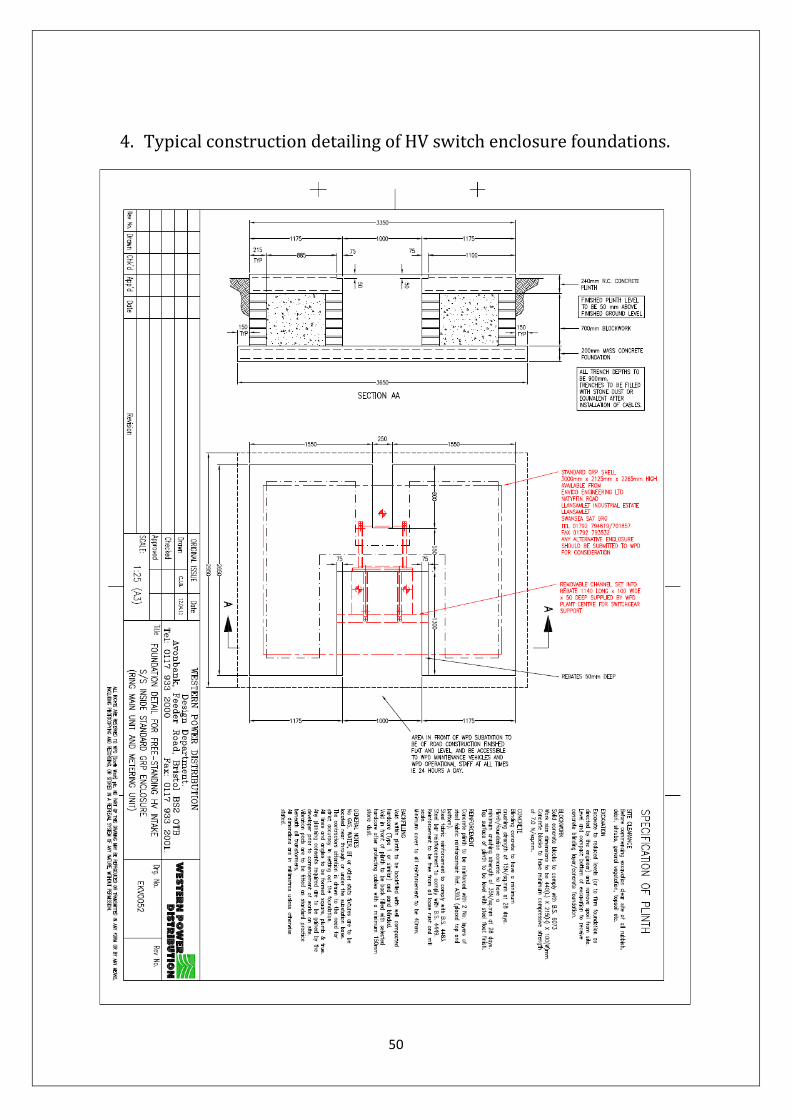
50
4. Typical construction detailing of HV switch enclosure foundations.
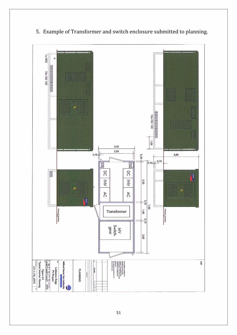
51
5. Example of Transformer and switch enclosure submitted to planning.

52
6. Site Access: longitudinal section and kerb profile.

53

54
7. Site Access: Swept path analysis

55
8. CCTV Layout
9.0 Details of Fibre Optic Connection to the Site.