REPUBLIC OF THE UNION OF MYANMAR MINISTRY OF …2.1 Lifebuoys 2.1.1 Lifebuoy specification Every...
302
REPUBLIC OF THE UNION OF MYANMAR MINISTRY OF TRANSPOR.T DEPARTMENT OF MARINE ADMINISTRATIOI.I NO.363/421, CORNEROF NIERCHANT & THEIN BYU ROAD, BOTATAUNG TOWNSI{IP, yANcON, MYANMAI{ P"0 BOX 194, Fax: +95 I 397641, E-mail: [email protected] Date: 23'd Octob er 2014 Directive (1312014) Life-Saving Appliances f,{eferences: (a) SOLAS 19'14 as amended (b) IMO Res MSC 48(66)/IMO Res MSC 207(81)/IMO Res MSC 218(82)/ IMO Res MSC272(85)/IMO Res MSC 293(87)tlMO Res MSC 320(89)/ IMO ftes MSC 368(93) (c) IMO Res A.689(17) /IIvIO ResMSC 54(66)/IMO Res MSC 81(70)l IMO Res MSC.200(80)/IM0 Res MSC.225(82)ilN\O Res MSC274(85)/ IMO ResMSC.295(87)/IMO ResMSC.32l(89)/ IMO Res MSC.323(89)/ IMO ResMSC.378(93) (d) trMO Res A s20(13) 1 The Departmentof Marine Administration eirculates this directive in the exercise of the power conferred by Section216-A (1) of the Myanmar Merchant Shipping Act 1923, asamended. 2 This directive appiies to all Myanrnar flagged ships engaged on trnternationatr voyages cornplying with requirements of the IntemationalConvention for Safety of Life at'Sea 1974, as amended. 3 The National Guidance and Standards for Life saving appliances are set out by Department of Marine Administration to fulfill the relevant requirements of the International Safetyof Life at Sea1974. as amended and above-mentioned references. Applicable to: All Ship - owners, Ship Operators, Flag State Surveyors. Recognized Organizations, Vlasters and Of'ficers of Myanmar FlaggedShips ng Maung Oo Director Generatr Departmentof Marine Administration
Transcript of REPUBLIC OF THE UNION OF MYANMAR MINISTRY OF …2.1 Lifebuoys 2.1.1 Lifebuoy specification Every...

REPUBLIC OF THE UNION OF MYANMAR
MINISTRY OF TRANSPOR.T
DEPARTMENT OF MARINE ADMINISTRATIOI.I
NO.363/421, CORNER OF NIERCHANT & THEIN BYU ROAD,BOTATAUNG TOWNSI{IP, yANcON, MYANMAI{
P"0 BOX 194, Fax: +95 I 397641, E-mail: [email protected]
Date: 23'd Octob er 2014
Directive (1312014)
Life-Saving Appliances
f,{eferences:
(a) SOLAS 19'14 as amended
(b) IMO Res MSC 48(66)/IMO Res MSC 207(81)/IMO Res MSC 218(82)/
IMO Res MSC272(85)/IMO Res MSC 293(87)tlMO Res MSC 320(89)/
IMO ftes MSC 368(93)
(c) IMO Res A.689(17) /IIvIO Res MSC 54(66)/IMO Res MSC 81(70)l
IMO Res MSC.200(80)/IM0 Res MSC.225(82)ilN\O Res MSC274(85)/
IMO ResMSC.295(87)/IMO ResMSC.32l(89)/ IMO Res MSC.323(89)/
IMO ResMSC.378(93)
(d) trMO Res A s20(13)
1 The Department of Marine Administration eirculates this directive in the exercise of the
power conferred by Section 216-A (1) of the Myanmar Merchant Shipping Act 1923, as amended.
2 This directive appiies to all Myanrnar flagged ships engaged on trnternationatr voyages
cornplying with requirements of the Intemational Convention for Safety of Life at'Sea 1974, as
amended.
3 The National Guidance and Standards for Life saving appliances are set out by Department
of Marine Administration to fulfill the relevant requirements of the International Safety of Life at
Sea 1974. as amended and above-mentioned references.
Applicable to: All Ship - owners, Ship Operators, Flag State Surveyors. RecognizedOrganizations, Vlasters and Of'ficers of Myanmar Flagged Ships
ng Maung OoDirector Generatr
Department of Marine Administration

Department of Marine Administration Ministry of Transport and Communications
Republic of the Union of Myanmar
2014
NATIONAL GUIDANCE FOR LIFE-SAVING APPLIANCE

National Guidance for Life-Saving Appliances Introduction This National Guidance is set out according to the directive (13/2014) and purpose is to provide national standards for life-saving appliances required by chapter III of the International Convention for the Safety of Life at Sea (SOLAS), 1974 as amended. On or after 1 July 1998, the requirements of this guidance will be mandatory under the International Convention for the Safety of Life at Sea (SOLAS), 1974, as amended. Any future amendment to the guidance will be adopted and brought into force in accordance with the procedure laid down in Article Vlll of that Convention.
Chapter I - General 1.1 Definitions 1.1.1 Convention means the International Convention for the Safety of Life at Sea, 1974, as amended.
1.1.2 Effective clearing of the ship is the ability of the free-fall lifeboat to move away from the ship after free-fall launching without using its engine.
1.1.3 Free-fall acceleration is the rate of change of velocity experienced by the occupants during launching of a free-fall lifeboat.
1.1.4 Free-fall certification height is the greatest launching height for which the lifeboat is to be approved, measured from the still water surface to the lowest point on the lifeboat when the lifeboat is in the launch configuration.
1.1.5 Launching ramp angle is the angle between the horizontal and the launch rail of the lifeboat in its launching position with the ship on even keel.
1.1.6 Launching ramp length is the distance between the stern of the lifeboat and the lower end of the launching ramp.
1.1.7 Regulation means a regulation contained in the annex to the Convention.
1.1.8 Retro-reflective material is a material which reflects in the opposite direction a beam of light directed on it. 1.1.9 Water-entry angle is the angle between the horizontal and the launch rail of the lifeboat when it first enters the water.
1

1.1.10 The terms used in this Code have the same meaning as those defined in regulation III/3. 1.1.11 Administration means Department of Marine Administration of the Republic of Union of Myanmar. 1.2 General requirements for life-saving appliances
1.2.1 Paragraph 1.2.2.7 applies to life-saving appliances on all ships.
1.2.2 Unless expressly provided otherwise or unless, in the opinion of the Administration having regard to the particular voyages on which the ship is constantly engaged, other requirements are appropriate, all life-saving appliances prescribed in this part shall:
.1 be constructed with proper workmanship and materials; .2 not be damaged in stowage throughout the air temperature range -30°C to +65°C and, in the case of personal life-saving appliances, unless otherwise specified, remain operational throughout the air temperature range -15°C to +40°C;
.3 if the yare unlikely to be immersed in seawater during their use, operate throughout the seawater temperature range -1°C to +30°C; .4 where applicable, be rot-proof, corrosion-resistant, and not be unduly affected by seawater, oil or fungal attack; .5 where exposed to sunlight, be resistant to deterioration; .6 be of international or vivid reddish orange, or a comparably highly visible colour on all parts where this will assist detection at sea;
.7 be fitted with retro-reflective material where it will assist in detection and in accordance with the recommendations of the Organization;*
.8 if they are to be used in a seaway, be capable of satisfactory operation in that environment; .9 be clearly marked with approval information including the Administration which approved it, and any operational restrictions; and .10 where applicable, be provided with electrical short circuit protection to prevent damage or injury.
* prefer to the Recommendation on the use and fitting of retro-reflective materials on life-saving appliances (resolution
A.658(16),as it may be amended).
2

1.2.3 The period of acceptability of life-saving appliances which are subject to deterioration with age is generally 10 years. Such life-saving appliances shall be marked with a means for determining their age or the date by which they must be replaced. Permanent marking with a date of expiry is the preferred method of establishing the period of acceptability. Batteries not marked with an expiration date may be used if they are replaced annually, or in the case of a secondary battery (accumulator), if the condition of the electrolyte can be readily checked. In the case of pyrotechnic life-saving appliances, the date of expiry shall be indelibly marked on the product by the manufacturer. Chapter II - Personal Life-Saving Appliances 2.1 Lifebuoys 2.1.1 Lifebuoy specification Every lifebuoy shall: .1 have an outer diameter of not more than 800 mm and an inner diameter of not less than 400 mm;
.2 be constructed of inherently buoyant material: it shall not depend upon rushes, cork shavings or granulated cork, any other loose granulated material or any air compartment which depends on inflation for buoyancy; .3 be capable of supporting not less than 14.5 kg of iron in fresh water for a period of 24 h; .4 have a mass of not less than 2.5 kg; .5 not sustain burning or continue melting after being totally enveloped in a fire for a period of 2 s; .6 be constructed to withstand a drop into the water from the height at which it is stowed above the waterline in the lightest seagoing condition or 30 m, whichever is the greater, without impairing either its operating capability or that of its attached components; .7 if it is intended to operate the quick release arrangement provided for the self-activated smoke signals and self-igniting lights, have a mass of not less than 4 kg; and
.8 be fitted with a grabline not less than 9.5 mm in diameter and not less than four times the outside diameter of the body of the buoy in length.
3

The grab line shall be secured at four equidistant points around the circumference of the buoy to form four equal loops.
2.1.2 Lifebuoy self-igniting lights Self-igniting lights required by regulation III/7.1.3 shall:
.1 be such that they cannot be extinguished by water; .2 be of white colour and capable of either burning continuously with a luminous intensity of not less than 2 cd in all directions of the upper `hemisphere or flashing (discharge flashing) at a rate of not less than 50 flashes and not more than 70 flashes per min with at least the corresponding effective luminous intensity; .3 be provided with a source of energy capable of meeting the requirement of paragraph 2.1.2.2 for a period of at least 2 h; and .4 be capable of withstanding the drop test required by paragraph 2.1.1.6.
2.1.3 Lifebuoy self-activating smoke signals Self-activating smoke signals required by regulation III/7.1.3 shall:
.1 emit smoke of a highly visible colour at a uniform rate for a period of at least 15 min when floating in calm water; .2 not ignite explosively or emit any flame during the entire smoke emission time of the signal; .3 not be swamped in a seaway;
.4 continue to emit smoke when fully submerged in water for a period of at least 10 s;
.5 be capable of withstanding the drop test required by paragraph 2.1.1.6; and .6 be provided with a quick-release arrangement that will automatically release and activate the signal and associated self - igniting Light connected to a lifebuoy having a mass of not more than 4 kg.
2.1.4 Buoyant lifelines Buoyant lifelines required by regulation III/7.1.2 shall:
.1 be non-kinking; .2 have a diameter of not less than 8 mm; and
.3 have a breaking strength of not less than 5 kN. 4

2.2 Lifejackets 2.2.1 General requirements for lifejackets 2.2.1.1 A lifejacket shall not sustain burning or continue melting after being totally enveloped in a fire for a period of 2 s.
2.2.1.2 Lifejackets shall be provided in three sizes in accordance with table 2.1. If a lifejacket fully complies with the requirements of two adjacent size ranges, it may be marked with both size ranges, but the specified ranges shall not be divided. Lifejackets shall be marked by either weight or height, or by both weight and height, according to table 2.1.
Table 2.1 Lifejacket sizing criteria Life Jacket
marking Infant Child Adult
User’s size Weight(kg) Height (cm)
less than 15 less than 15
15 or more but less than 43 100 or more but less than 155
43 or more 100 or more
2.2.1.3 If an adult lifejacket is not designed to fit persons weighing up to 140 kg and with a chest girth of up to 1,750 mm, suitable accessories shall be available to allow it to be secured to such persons.
2.2.1.4 The in-water performance of a lifejacket shall be evaluated by comparison to the performance of a suitable size standard reference lifejacket, i.e. reference test device (RTD) complying with the recommendations of the Organization. *
2.2.1.5 An adult lifejacket shall be so constructed that: .1 at least 75% of persons who are completely unfamiliar with the Lifejacket can correctly don it within a period of 1 min without assistance, guidance or prior demonstration;
*Refer to the Revised Recommendation on testing of life-saving appliance (resolution MSC. 81(70),as amended).
5

.2 after demonstration, all persons can correctly don it within a period of 1 min without assistance; .3 it is clearly capable of being worn in only one way or inside-out and, if donned incorrectly, it is not injurious to the wearer; .4 the method of securing the Lifejacket to the wearer has quick and positive means of closure that do not require tying of knots; .5 it is comfortable to wear; and .6 it allows the wearer to jump into the water from a height of at least 4.5 m while holding on to the lifejacket, and from a height of at least 1m with arms held overhead, without injury and without dislodging or damaging the lifejacket or its attachments.
2.2.1.6 When tested according to the recommendations of the Organization on at least 12 persons, adult lifejackets shall have sufficient buoyancy and stability in calm fresh water to: .1 lift the mouth of exhausted or unconscious persons by an average height of not less than the average provided by the adult RTD minus 10 mm; .2 turn the body of unconscious, face down persons in the water to a position where the mouth is clear of the water in an average time not exceeding that of the RTD plus 1 s, with the number of persons not turned by the lifejacket no greater than that of the RTD;
.3 incline the body backwards from the vertical position for an average torso angle of not less than that of the RTD minus 10°; .4 lift the head above horizontal for an average face plane angle of not less than that of the RTD minus 10°; and .5 return at Least as many wearers to a stable face-up position after being destabilized when floating in the flexed foetal position* as with the RTD when tested on the wearers in the same manner.
2.2.1.7 An adult lifejacket shall allow the person wearing it to swim a short distance and to board a survival craft. *Refer to the illustration on page 9 of the IMO Pocket Guide for Cold Water Survival,2012 Edition, and to the Revised
Recommendation on testing of life-saving appliances resolution MSC.81(70),as amended).
6

2.2.1.8 An infant or child lifejacket shall perform the same as an adult lifejacket except as follows:
.1 donning assistance is permitted for small children and infants; .2 the appropriate child or infant RTD shall be used in place of the adult RTD; .3 assistance may be given to board a survival craft, but wearer mobility shall not be reduced to any greater extent than by the appropriate size RTD. .4 for infants the jump and drop tests shall be exempted; .5 for children, five of the nine subjects shall perform the jump and drop tests; and .6 in lieu of paragraph 2.2.1.8.5, manikins may be substituted for human test subjects.
2.2.1.9 With the exception of freeboard and self-righting performance, the requirements for infant lifejackets may be relaxed, if necessary, in order to:
.1 facilitate the rescue of the infant by a caretaker; .2 allow the infant to be fastened to a caretaker and contribute to keeping the infant close to the caretaker; .3 keep the infant dry, with free respiratory passages; .4 protect the infant against bumps and jolts during evacuation; and
.5 allow a caretaker to monitor and control heat loss by the infant.
2.2.1.10 In addition to the markings required by paragraph 1.2.2.9, an infant or child lifejacket shall be marked with: .1 the size range in accordance with paragraph 2.2.1.2; and
.2 an “infant” or “child” symbol as shown in the “infant’s lifejacket” or “child’s lifejacket” symbol adopted by the Organization. *
2.2.1.11 A lifejacket shall have buoyancy which is not reduced by more than 5% after 24 h submersion in fresh water. * Refer to Symbols related to life-saving appliances and arrangements (resolution A. 760(18),as it may be amended).
7

2.2.1.12 The buoyancy of a lifejacket shall not depend on the use of loose granulated materials.
2.2.1.13 Each lifejacket shall be provided with means of securing a lifejacket light as specified in paragraph2.2.3 such that it shall be capable of complying with paragraphs 2.2.1.5.6 and 2.2.3.1.3.
2.2.1.14 Each lifejacket shall be fitted with a whistle firmly secured by a lanyard.
2.2.1.15 Lifejacket lights and whistles shall be selected and secured to the lifejacket in such a way that their performance in combination is not degraded.
2.2.1.16 A lifejacket shall be provided with a releasable buoyant line or other means to secure it to a lifejacket worn by another person in the water.
2.2.1.17 A lifejacket shall be provided with a suitable means to allow a rescuer to lift the wearer from the water into a survival craft or rescue boat. 2.2.2 Inflatable lifejacket A lifejacket which depends on inflation for buoyancy shall have not less than two separate compartments, shall comply with the requirements of paragraph 2.2.1 and shall:
.1 inflate automatically upon immersion, be provided with a device to permit inflation by a single manual motion and be capable of having each chamber inflated by mouth;
.2 in the event of loss of buoyancy in any one compartment be capable of complying with the requirements of paragraphs 2.2.1.5, 2.2.1.6 and 2.2.1.7; and .3 comply with the r requirements of paragraph 2.2.1.11 after inflation by means of the automatic mechanism.
8

2.2.3 Lifejacket lights 2.2.3.1 Each lifejacket light shall:
.1 have a luminous intensity of not less than 0.75 cd in all directions of the upper hemisphere; .2 have as ounce of energy capable of providing a luminous intensity of 0.75 cd for a period of at least 8 h; .3 be visible over as great a segment of the upper hemisphere as is practicable when attached to a lifejacket; and .4 be of white colour.
2.2.3.2 If the light referred to in paragraph 2.2.3.1 is a flashing light, it shall, in addition: .1 be provided with a manually operated switch; and .2 flash ata rate of not less than 50 flashes and not more than 70 flashes per minute with an effective luminous intensity of at least 0.75 cd .2.3 Immersion suits 2.3 Immersion suits 2.3.1 General requirements for immersion suits 2.3.1.1 An immersion suit shall be constructed with waterproof materials such that:
.1 it can be unpacked and donned without assistance within 2 min, taking into account donning of any associated clothing*, donning of a Lifejacket if the immersion suit must be worn in conjunction with a Lifejacket to meet the requirements of paragraph 2.3.1.2, and inflation of orally inflatable chambers if fitted;
.2 it will not sustain burning or continue melting after being totally enveloped in a fire for a period of 2 s;
.3 it will cover the whole body with the exception of the face, except that covering for the hands may be provided by separate gloves which shall be permanently attached to the suit;
* Refer to paragraph 3.1.3 of the Revised Recommendation on testing of life-saving appliances (resolution MSC.(81(70), as
amended).
9
.4 it is provided with arrangements to minimize or reduce free air in the Legs of the suit; and
.5 following a jump from a height of not less than 4.5 m into the water there is no undue ingress of water into the suit.
2.3.1.2 An immersion suit on its own, or worn in conjunction with a lifejacket if necessary, shall have sufficient buoyancy and stability in calm fresh water to:
.1 lift the mouth of an exhausted or unconscious person clear of the water by not less than 120 mm; and .2 allow the wearer to turn from a face-down to a face-up position in not more than 5 s.
2.3.1.3 An immersion suit shall permit the person wearing it, and also wearing a lifejacket if the immersion suit is to be worn in conjunction with a lifejacket, to:
.1 climb up and down a vertical ladder at least 5 m in length; .2 perform normal duties associated with abandonment; .3 jump from a height of not less than 4.5 m into the water without damaging or dislodging the immersion suit or its attachments, or being injured; and .4 swim a short distance through the water and board a survival craft.
2.3.1.4 An immersion suit which has buoyancy and is designed to be worn without a lifejacket shall be fitted with a light complying with the requirements of paragraph 2.2.3 and the whistle prescribed by paragraph 2.2.1.14.
2.3.1.5 An immersion suit which has buoyancy and is designed to be worn without a lifejacket shall be provided with a releasable buoyant line or other means to secure it to a suit worn by another person in the water.
2.3.1.6 An immersion suit which has buoyancy and is designed to be worn without a lifejacket shall be provided with a suitable means to allow a rescuer to lift the wearer from the water into a survival craft or rescue boat.
2.3.1.7 If an immersion suit is to be worn in conjunction with a lifejacket, the lifejacket shall be worn over the immersion suit. Persons wearing such an immersion
10

suit shall be able to don a lifejacket without assistance. The immersion suit shall be marked to indicate that it must be worn in conjunction with a compatible lifejacket.
2.3.1.8 An immersion suit shall have buoyancy which is not reduced by more than 5% after 24 h submersion in fresh water and does not depend on the use of loose granulated materials. 2.3.2 Thermal performance requirements for immersion suits 2.3.2.1 An immersion suit made of material which has no inherent insulation shall be:
.1 marked with instructions that it must be worn in conjunction with warm clothing; and .2 so constructed that, when worn in conjunction with warm clothing, and with a lifejacket if the immersion suit is to be worn with a lifejacket, the immersion suit continues to provide sufficient thermal protection, following one jump by the wearer into the water from a height of 4.5 m, ensure that when it is worn for a period of 1 h in calm circulating to water at a temperature of 5°C, the wearer's body core temperature does not fall more than 2°C.
2.3.2.2 An immersion suit made of material with inherent insulation, when worn either on its own or with a lifejacket, if the immersion suit is to be worn in conjunction with a lifejacket, shall provide the wearer with sufficient thermal insulation, following one jump into the water from a height of 4.5 m, to ensure that the wearer's body core temperature does not fall more than 2°C after a period of 6 h immersion in calm circulating water at a temperature of between 0°C and 2°C. 2.4 Anti-exposure suits 2.4.1 General requirements for anti-exposure suits 2.4.1.1 An anti-exposure suit shall be constructed with waterproof materials such that it: .1 provides inherent buoyancy of at least 70N;
.2 is made of material which reduces the risk of heat stress during rescue and evacuation operations;
11

.3 covers the whole body except, where the Administration so permits, the feet; covering for the hands and head may be provided by separate gloves and a hood, both of which shall be permanently attached to the suit; .4 can be unpacked and donned without assistance within 2 min; .5 does not sustain burning or continue melting after being totally enveloped in a fire for a period of 2 s; .6 is equipped with a pocket for a portable VHF telephone; and
.7 has a lateral field of vision of at least 120°.
2.4.1.2 The anti-exposure suits shall permit the person wearing it, to: .1 climb up and down a vertical ladder of at least 5 m in length;
.2 jump from a height of not less than 4.5 m into the water with feet first, without or dislodging the suit or its attachments, or being injured; .3 swim through the water at least 25 m and board a survival craft;
.4 don a lifejacket without assistance; .5 perform all duties associated with abandonment, assist others and operate a rescue boat.
2.4.1.3 An anti-exposure suit shall be fitted with a light complying with the requirements of paragraph 2.2.3 such that it shall be capable of complying with paragraphs 2.2.3.1.3 and 2.4.1.2.2, and the whistle prescribed by paragraph 2.2.1.14. 2.4.2 Thermal performance requirements for anti-exposure suits 2.4.2.1 An anti-exposure suits shall:
.1 if made of material which has no inherent insulation, be marked with instructions that it must be worn in conjunction with warm clothing;
.2 be so constructed that, when worn as marked and following one jump into the water which totally submerges the wearer, the suit continues to provide sufficient thermal protection to ensure that when it is worn in calm circulating water at a temperature of 5°C, the wearer’s body core temperature does not fall at a rate of more than 1.5°C per hour, after the first 0.5 h.
12

2.4.3 Stability requirements A person in fresh water wearing an anti-exposure suits complying with the requirements of this section shall be able to turn from a face-down to a face-up position in not more than 5 s and shall be stable face-up. The suit shall have no tendency to turn the wearer face-down in moderate sea condition. 2.5 Thermal protective aids 2.5.1 A thermal protective aid shall be made of waterproof material having a thermal conductance of not more than 7800 W/(m2K) and shall be so constructed that, when used to enclose a person, it shall reduce both the convective and evaporative heat loss from the wearer's body.
2.5.2 The thermal protective aid shall: .1 cover the whole body of persons of all sizes wearing a lifejacket with
the exception of the face. Hands shall also be covered unless permanently attached gloves are provided;
.2 be capable of being unpacked and easily donned without assistance in a survival craft or rescue boat; and
.3 permit the wearer to remove it in the water in not more than 2 min, if it impairs ability to swim.
2.5.3 The thermal protective aid shall function properly throughout an air temperature range -30°C to +20°C. Chapter III - Visual Signals 3.1 Rocket parachute flares 3.1.1 The rocket parachute flare shall:
.1 be contained in a water-resistant casing; .2 have brief in striations or diagrams clearly illustrating the use of the rocket parachute flare printed on its casing; .3 have integral means of ignition; and .4 be so designed as not to cause discomfort to the person holding the casing when used in accordance with the manufacturer's operating instructions.
13

3.1.2 The rocket shall, when fired vertically, reach an altitude of not less than 300 m. At or near the top of its trajectory, the rocket shall eject a parachute flares which shall:
.1 burn with a bright red colour; .2 burn uniformly with an average luminous intensity of not less than 30,000 cd; .3 have a burning period of not less than 40 s; .4 have a rate of descent of not more than 5 m/s; and .5 not damage its parachute or attachments while burning.
3.2 Hand flares 3.2.1 The hand flare shall:
.1 be contained in a water-resistant casing; .2 have brief in striations or diagrams clearly illustrating the use of the hand flare printed on its casing; .3 have a self-contained means of ignition; and .4 be so designed as not to cause discomfort to the person holding the casing and not endanger the survival craft by burning or glowing residues when used in accordance with the manufacturer's operating instructions.
3.2.2 The hand flare shall: .1 burn with a bright red colour; .2 burn uniformly with an average luminous intensity of not less than 15,000 cd; .3 have a burning period of not less than 1 min; and .4 continue to burn after having been immersed for a period of 10 s under 100 mm of water.
3.3 Buoyant smoke signals 3.3.1 The buoyant smoke signal shall:
.1 be contained in a water-resistant casing; .2 not ignite explosively when used in accordance with the manufacturer's operating instructions; and
14

.3 have brief instructions or diagrams clearly illustrating the use of the buoyant smoke signal printed on its casing.
3.3.2 The buoyant smoke signal shall: .1 emit smoke of a highly visible colour at a uniform rate for a period of not less than 3 min when floating in calm water; .2 not emit any flame during the entire smoke emission time; .3 not be swamped in a seaway; and .4 continue to emit smoke when submerged in water for a period of 10 s under 100 mm of water.
Chapter IV - Survival Craft 4.1 General requirements for Liferafts 4.1.1 Construction of Liferafts 4.1.1.1 Every Liferaft shall be so constructed as to be capable of withstanding exposure for 30 days afloat in all sea conditions.
4.1.1.2 The Liferaft shall be so constructed that when it is dropped into the water from a height of 18 m, the Liferaft and its equipment will operate satisfactorily. If the Liferaft is to be stowed at a height of more than 18 m above the waterline in the lightest seagoing condition, it shall be of a type which has been satisfactorily drop-tested from at least that height.
4.1.1.3 The floating Liferaft shall be capable of withstanding repeated jumps on to it from a height of at least 4.5 m above its floor both with and without the canopy erected.
4.1.1.4 The Liferaft and its fittings shall be so constructed as to enable it to be towed at a speed of 3 knots in calm water when loaded with its full complement of persons and equipment and with one of its sea-anchors streamed.
4.1.1.5 The Liferaft shall have a canopy to protect the occupants from exposure which is automatically set in place when the Liferaft is launched and waterborne. The canopy shall comply with the following:
15

.1 it shall provide insulation against heat and cold by means of either two layers of material separated by an air gap or other equally efficient means. Means shall be provided to prevent accumulation of water in the air gap;
.2 its interior shall be of a colour that does not cause discomfort to the occupants;
.3 each entrance shall be clearly indicated and be provided with efficient adjustable closing arrangements which can be easily and quickly opened by persons clothed in immersion suits from inside and outside, and closed from inside, the Liferaft so as to permit ventilation but exclude sea water, wind and cold. Liferafts accommodating more than eight persons shall have at least two diametrically opposite entrances; .4 it shall admit sufficient air for the occupants at all times, even with the
entrances closed; .5 it shall be provided with at least one viewing port; .6 it shall be provided with means for collecting rain water; .7 it shall be provided with means to mount a survival craft radar transponder at a height of at least 1 m above the sea; and .8 it shall have sufficient headroom for sitting occupants under all parts of the canopy.
4.1.2 Minimum carrying capacity and mass of Liferafts 4.1.2.1 No Liferaft shall be approved which has a carrying capacity of less than six persons calculated in accordance with the requirements of paragraph 4.2.3 , or 4.3.3 as appropriate.
4.1.2.2 Unless the Liferaft is to be launched by an approved launching appliance complying with the requirements of section 6.1 or is not intended for easy side-to-side transfer, the total mass of the Liferaft, its container and its equipment shall not be more than 185 kg. 4.1.3 Liferaft fittings 4.1.3.1 Lifelines shall be securely becketed around the inside and outside of the Liferaft.
16

4.1.3.2 The Liferaft shall be fitted with an efficient painter or length equal to not less than 10 m plus the distance from the stowed position to the waterline in the lightest seagoing condition or 15 m whichever is the greater. The breaking strength of the painter system, including its means of attachment to the Liferaft, except the weak link required by paragraph 4.1.6, shall be not less than 15.0 kN for Liferafts permitted to accommodate more than 25 persons, not less than 10.0 kN for Liferafts permitted to accommodate 9 to 25 persons and not less than 7.5 kN for any other Liferaft.
4.1.3.3 A manually controlled exterior light shall be fitted to the uppermost portion of the Liferaft canopy or structure. The light shall be white and be capable of operating continuously for at least 12 h with a luminous intensity of not less than 4.3 cd in all directions of the upper hemisphere. However, if the light is a flashing light it shall flash at a rate of not less than 50 flashes and not more than 70 flashes per min for the 12 h operating period with an equivalent effective luminous intensity. The lamp shall light automatically when the canopy is erected. Batteries shall be of a type that does not deteriorate due to dampness or humidity in the stowed Liferaft.
4.1.3.4 A manually controlled interior light shall be fitted inside the Liferaft capable of continuous operation for a period of at least 12 h. It shall light automatically when the canopy is erected and shall produce an arithmetic mean luminous intensity of not less than 0.5 cd when measured over the entire upper hemisphere to permit reading of survival and equipment instructions. Batteries shall be of a type that does not deteriorate due to damp or humidity in the stowed Liferaft. 4.1.4 Davit-launched Liferafts 4.1.4.1 In addition to the above requirements, a Liferaft for use with an approved launching appliance shall:
.1 when the Liferaftis Loaded with its full complement of persons and equipment, be capable of withstanding a lateral impact against the ship's side at an impact velocity of not less than 3.5 m/s and also a drop into the water from a height of not less than 3 m without damage that will affect its function;
17

.2 be provided with means for bringing the Liferaft alongside the embarkation deck and holding it securely during embarkation.
4.1.4.2 Every passenger ship davit-launched Liferaft shall be so arranged that it can be rapidly boarded by its full complement of persons.
4.1.4.3 Every cargo ship davit-launched Liferaft shall be so arranged that it can be boarded by its full complement of persons in not more than 3 min from the time the instruction to board is given. 4.1.5 Equipment 4.1.5.1 The normal equipment of every Liferaft shall consist of:
.1 one buoyant rescue quoit, attached to not less than 30 m of buoyant line; .2 one knife of the non-folding type having a buoyant handle and lanyard attached and stowed in a pocket on the exterior of the canopy near the point at which the painter is attached to the Liferaft. In addition, a Liferaft which is permitted to accommodate 13 persons or more shall be provided with a second knife need not be of the non-foldingtype; .3 or a Liferaft which is permitted to accommodate not more than 12 persons, one buoyant bailer. For a Liferaft which is permitted to accommodate 13 persons or more, two buoyant bailers; .4 two sponges;
.5 two sea-anchors each with a shock resistant hawser and tripping line if fitted, one being spare and the other permanently attached to the Liferaft in such a way that when the Liferaft inflates or is waterborne it will cause the Liferaft to lie oriented to the wind in the most stable manner. The strength of each sea-anchor and its hawser and tripping Line if fitted shall be adequate in all sea conditions. The sea-anchors shall have means to prevent twisting of the line and shall be of a type which is unlikely to turn inside out between its shroud lines. The sea - anchor permanently attached to davit launched Liferafts and Liferafts fitted on passenger ships shall be arranged for manual deployment only. All other Liferafts are to have the sea-anchor deployed automatically when the Liferaft inflates;
18

.6 two buoyant paddles; .7 three tin openers and a pair of scissors. Safety knives containing special tin-opener blades are satisfactory for this requirement; .8 one first-aid outfit in a waterproof case capable of being closed tightly after use; .9 one whistle or equivalent sound signal; .10 four rocket parachute flares complying with the requirements of section 3.1; .11 six hand flares complying with the requirements of section 3.2; .12 two buoyant smoke signals complying with the requirements of section 3.3; .13 one waterproof electric torch suitable for Morse signalling together with one spare set of batteries and one spare bulb in a water proof container; .14 an efficient radar reflector, unless a survival craft radar transponder is stowed in the Liferaft; .15 one daylight signalling mirror with instructions on its use for signalling to ships and aircraft; .16 one copy of the life-saving signals referred to in regulation V/16 on a water proof card or in a waterproof container; .17 one set of fishing tackle; .18 a food ration consisting of not less than 10,000 kJ (2,400 kcal) for each person the Liferaft is permitted to accommodate. These rations shall be palatable, edible hrough out the marked life, and packed in a manner which can be readily divided and easily opened, taking into account immersion suit gloved hands.*
The rations shall be packed in permanently sealed metal containers or vacuum packed in a flexible packaging material with a negligible vapour transmission rate (<0.1 g/m2 per 24 h at 23ºC/85% relative humidity) when tested to a standard acceptable to the Administration. Flexible packaging materials shall be further protected by outer packaging, if needed, to prevent physical damage to the food ration and other items as result of sharp edges. The packaging shall be clearly marked with date of packing and date of expiry, the production lot
19

number, the content in the package and instructions for use. Food rations complying with the requirements of an international standard acceptable to the Organization are acceptable in compliance with these requirements;
.19 1.5 ⋉ of fresh water for each person the Liferaft is permitted to
accommodate, of which either 0.5 ⋉ per person may be replaced by a de-salting apparatus capable of producing an equal amount of fresh water in 2 days or 1 ⋉ per person may be replaced by a manually powered reverse osmosis desalinate or, as descry ybedin paragraph 4.4.7.5,capable of producing an equal amount of fresh water in 2 days. The water shall satisfy suitable international requirements for chemical and microbiological content, and shall be packed in sealed watertight containers that are of corrosion resistant material or are treated to be corrosion resistant. Flexible packaging materials, if used, shall have a negligible vapour transmission rate (<0.1 g/m2 per 24 h at 23ºC / 85% relative humidity) when tested to a standard acceptable to the Administration, except that individually packaged portions within a larger container need not meet this vapour transmission requirement. Each container shall have a method of spill proof reclose, except for individually packaged portions of less than 125 ml. Each container shall be clearly marked with date of packing and date of expiry, the production lot number, the quantity of water in the container, and instructions for consumption. The containers shall be easy to open, taking into account immersion suit gloved hands. Water for emergency drinking complying with the requirements of an international standard acceptable to the Organization* is acceptable in compliance with these requirements;
.20 one rustproof graduated drinking vessel;
.21 anti - seasickness medicine sufficient for at least 48 h and one seasickness bag for each person the Liferaft is permitted to accommodate;
*Refer the recommendations of the International Organization for standardization, in particular publication ISO 18813:2006 Ships and marine technology-Survival equipment for survival craft and rescue boats.
20

.22 instructions on how to survive *; .23 instructions for immediate action; and .24 thermal protective aids complying with the requirements of paragraph 2.5 sufficient for 10% of the number of persons the Liferaft is permitted to accommodate or two, whichever is the greater.
4.1.5.2 The marking required by paragraphs 4.2.6.3.5 and 4.3.6.7 on Liferafts equipped in accordance with paragraph 4.1.5.1 shall be "SOLAS A PACK" in block capitals of the Roman alphabet.
4.1.5.3 In the case of passenger ships engaged on short international voyages of such a nature and duration that, in the opinion of the Administration, not all the items specified in paragraph 4.1.5.1 are necessary, the Administration may allow the Liferafts carried on any such ships to be provided with the equipment specified in paragraphs 4.1.5.1.1 to 4.1.5.1.6 inclusive, 4.1.5.1.8, 4.1.5.1.9, 4.1.5.1.13 to 4.1.5.1.16 inclusive and 4.1.5.1.21 to 4.1.5.1.24 inclusive and one half of the equipment specified in paragraphs 4.1.5.1.10 to 4.1.5.1.12 inclusive. The marking required by paragraphs4.2.6.3.5 and 4.3.6.7 on such Liferafts shall be "SOLAS B PACK" in block capitals of the Roman alphabet.
4.1.5.4 Where appropriate the equipment shall be stowed in a container which, if it is not an integral part of, or permanently attached to, the Liferaft, shall be stowed and secured inside the Liferaft and be capable of floating in water for at least 30 min without damage to its contents. 4.1.6 Float-free arrangements for Liferafts 4.1.6.1 Painter system
The Liferaft painter system shall provide a connection between the ship and the Liferaft and shall be so arranged as to ensure that the Liferaft when released and, in the case of an inflatable Liferaft, inflated is not dragged under by the sinking ship.
4.1.6.2 Weak link If a weak link is used in the float-free arrangement, it shall:
.1 not be broken by the force required to pull the painter from the Liferaft container;
* Refer to the Instructions for action in survival Craft (resolution A. 657(16).
21

.2 if applicable, be of sufficient strength to permit the inflation of the Liferaft; and .3 break under a strain of 2.2 ± 0.4 kN.
4.1.6.3 Hydro static release units If a hydrostatic release unit is used in the float-free arrangements, it shall:
.1 be constructed of compatible materials so as to prevent malfunction of the unit. Galvanizing or other forms of metallic coating on parts of the hydrostatic release unit shall not be accepted; .2 automatically release the liferaft at a depth of not more than 4 m; .3 have drains to prevent the accumulation of water in the hydrostatic chamber when the unit is in its normal position; .4 be so constructed as to prevent release when seas wash over the unit; .5 be permanently marked on its exterior with its type and serial number; .6 be permanently marked on the unit or identification plate securely attached to the unit, with the date of manufacture, type and serial number and whether the unit is suitable for use with a Liferaft with a capacity of more than 25 persons; .7 be such that each part connected to the painter system has a strength of not less than that required for the painter; and .8 if disposable, in lieu of the requirement in paragraph 4.1.6.3.6 be marked with a means of determining its date of expiry.
4.2 Inflatable Liferafts 4.2.1 Inflatable Liferafts shall comply with the requirements of section 4.1and, in addition, shall comply with the requirements of this section.
4.2.2 Construction of inflatable Liferafts 4.2.2.1 The main buoyancy chamber shall be divided into not less than two separate compartments, each inflated through a non return inflation valve on each compartment. The buoyancy chambers shall be so arranged that, in the event of any one of the compartments being damaged or failing to inflate, the intact compartments shall be able to support, with positive freeboard over the Liferaft's entire periphery, the number of persons which the Liferaft is permitted to accommodate each having a mass of 82.5 kg and seated in their normal positions.
22

4.2.2.2 The floor of the Liferaft shall be waterproof and shall be capable of being sufficiently insulated against cold either:
.1 by means of one or more compartments that the occupants can inflate, or which inflate automatically and can be deflated and reinflated by the occupants; or .2 by other equally efficient means not dependent on inflation.
4.2.2.3 The Liferaft shall be capable of being inflated by one person. The Liferaft shall be inflated with a nontoxic gas. The inflation system, including any relief valves installed in compliance with paragraph 4.2.2.4, shall comply with the requirements of an international standard acceptable to the Organization*. Inflation shall be completed within a period of 1 min at an ambient temperature of between 18°C and 20°C and within a period of 3 min at an ambient temperature of -30°C. After inflation the Liferaft shall maintain its form when loaded with its full complement of persons and equipment.
4.2.2.4 Each inflatable compartment shall be capable of withstanding a pressure equal to at least 3 times the working pressure and shall be prevented from reaching a pressure exceeding twice the working pressure either by means of relief valves or by a limited gas supply. Means shall be provided for fitting the topping up pump or bellows required by paragraph 4.2.9.1.2 so that the working pressure can be maintained. 4.2.3 Carrying capacity of inflatable Liferafts
The number of persons which a Liferaft shall be permitted to accommodate shall be equal to the lesser of: .1 the greatest whole number obtained by dividing by 0.096 the volume, measured in cubic metres of the main buoyancy tubes (which for this purpose shall include neither the arches nor the thwarts if fitted) when inflated; or
.2 the greatest whole number obtained by dividing by 0.372 the inner horizontal cross-sectional area of the Liferaft measured in square metres (which for this urpose may include the thwart or thwarts, if fitted) measured to the innermost edge of the buoyancy tubes; or
*Refer to the recommendation of the Internationl Organization for Standardization, in particular publication ISO 15738: 2002 Ships and marine technology-Gas inflation systems for inflatable life-saving appliances.
23

.3 the number of persons having an average mass of 82.5 kg, all wearing either immersion suits and Lifejackets or, in the case of davit-Launched Liferafts, Lifejackets, that can be seated with sufficient comfort and headroom without interfering with the operation of any of the Liferaft's equipment.
4.2.4 Access into inflatable Liferafts 4.2.4.1 At least one entrance shall be fitted with a boarding ramp, capable of supporting a person weighing 100 kg sitting or kneeling and not holding onto any other part of the Liferaft, to enable persons to board the Liferaft from the sea. The boarding ramp shall be so arranged as to prevent significant deflation of the Liferaft if the ramp is damaged. In the case of a davit-launched Liferaft having more than one entrance, the boarding ramp shall be fitted at the entrance opposite the bow sing lines and embarkation facilities.
4.2.4.2 Entrances not provided with a boarding ramp shall have a boarding ladder, the lowest step of which shall be situated not less than 0.4 m below the Liferaft's light waterline.
4.2.4.3 There shall be means inside the Liferaft to assist persons to pull themselves into the Liferaft from the ladder.
4.2.5 Stability of inflatable Liferafts 4.2.5.1 Every inflatable Liferaft shall be so constructed that, when fully inflated and floating with the canopy uppermost, it is stable in a seaway.
4.2.5.2 The stability of the Liferaft when in the inverted position shall be such that it can be righted in a seaway and in calm water by one person.
4.2.5.3 The stability of the Liferaft when loaded with its full complement of persons and equipment shall be such that it can be towed at speeds of up to 3 knots in calm water.
4.2.5.4 The Liferaft shall be fitted with water pockets complying with the following requirements:
24

.1 the water pockets shall be of a highly visible colour; .2 the design shall be such that the pockets fill to at Least 60% of their capacity within 25 s of deployment; .3 the pockets shall have an aggregate capacity of at Least 220 l for Liferafts up to 10 persons; .4 the pockets for Liferafts certified to carry more than 10 persons shall have an aggregate capacity of not less than 20 N l where N = number of persons carried; and .5 the pockets shall be positioned symmetrically round the circumference of the Liferaft. Means shall be provided to enable air to readily escape from underneath the Liferaft.
4.2.6 Containers for inflatable Liferafts 4.2.6.1 The Liferaft shall be packed in a container that is:
.1 so constructed as to withstand hard wearunder conditions encountered at sea; .2 of sufficient inherent buoyancy when packed with the Liferaft and its equipment, to pull the painter from within and to operate the inflation mechanism should the ship sink; and .3 as far as practicable watertight, except for drain holes in the container bottom.
4.2.6.2 The Liferaft shall be packed in its container in such a way as to ensure, as far as possible, that the waterborne Liferaft inflates in an upright position on breaking free from its container.
4.2.6.3 The container shall be marked with: .1 maker's name or trade mark; .2 serial number; .3 name of approving authority and the number of persons it is permitted to carry; .4 SOLAS; .5 type of emergency pack enclosed; .6 date when last serviced; .7 length of painter;
25

.8 mass of the packed Liferaft, if greater than 185 kg; .9 maximum permitted height of stowage above waterline (depending on drop-test height and length of painter); and .10 launching instructions.
4.2.7 Markings on inflatable Liferafts 4.2.7.1 The Liferaft shall be marked with:
.1 maker's name or trade mark; .2 serial number; .3 date of manufacture (month and year); .4 name of approving authority; .5 name and place of servicing station where it was last serviced; and .6 number of persons it is permitted to accommodate over each entrance in characters not less than 100 mm in height of a colour contrasting with that of the Liferaft.
4.2.7.2 Provision shall be made for marking each Liferaft with the name and port of registry of the ship to which it is to be fitted, in such a form that the ship identification can be changed at any time without opening the container. 4.2.8 Davit-launched inflatable Liferafts 4.2.8.1 In addition to complying with the above requirements, a Liferaft for use with an approved launching appliance shall, when suspended from its lifting hook or bridle, withstand a load of:
.1 4 times the mass of its full complement of persons and equipment, at an ambient temperature and a stabilized Liferaft temperature of 20 ± 3°C with all relief valves inoperative; and .2 1.1 times the mass of its full complement of persons and equipment at an ambient temperature and a stabilized Liferaft temperature of -30°C with all relief valves operative.
4.2.8.2 Rigid containers for Liferafts to be launched by a launching appliance shall be so secured that the container or parts of it are prevented from falling into the sea during and after inflation and launching of the contained Liferaft.
26

4.2.9 Additional equipment for inflatable Liferafts 4.2.9.1 In addition to the equipment required by paragraph 4.1.5 every inflatable Liferaft shall be provided with:
.1 one repair outfit for repairing punctures in buoyancy compartments; and .2 one topping-up pump or bellows.
4.2.9.2 The knives required by paragraph 4.1.5.1.2 shall be safety knives, and the tin openers and scissors required by paragraph 4.1.5.1.7shall be of the safety type. 4.3 Rigid Liferafts 4.3.1 Rigid Liferafts shall comply with the requirements of section 4.1 and, in addition. shall comply with the requirements of this section.
4.3.2 Construction of rigid Liferafts 4.3.2.1 The buoyancy of the Liferaft shall be provided by approved inherently buoyant material placed as near as possible to the periphery of the Liferaft. The buoyant material shall be fire-retardant or be protected by a fire-retardant covering.
4.3.2.2 The floor of the Liferaft shall prevent the ingress of water and shall effectively support the occupants out of the water and insulate them from cold. 4.3.3 Carrying capacity of rigid Liferafts The number of persons which a Liferaft shall be permitted to accommodate shall be equal to the lesser of:
.1 the greatest whole number obtained by dividing by 0.096 the volume, measured in cubic metres of the buoyancy material multiplied by a factor of 1 minus the specific gravity of that material; or .2 the greatest whole number obtained by dividing by 0.372 the horizontal cross – sectional area of the floor of the Liferaft measured in square metres; or .3 the number of persons having an average mass of 82.5 kg, all wearing immersion suits and Lifejackets, that can be seated with sufficient comfort and headroom without interfering with the operation of any of the Liferaft's equipment.
27

4.3.4 Access into rigid Liferafts 4.3.4.1 At least one entrance shall be fitted with a boarding ramp, capable of supporting a person weighing 100 kg sitting or kneeling and not holding onto any other part of the Liferaft, to enable persons to board the Liferaft from the sea. In the case of a davit-launched Liferaft having more than one entrance, the boarding ramp shall be fitted at the entrance opposite to the bowsing and embarkation facilities.
4.3.4.2 Entrances not provided with a boarding ramp shall have a boarding ladder, the lowest step of which shall be situated not less than 0.4 m below the Liferafts light waterline.
4.3.4.3 There shall be means inside the Liferaft to assist persons to pull themselves into the Liferaft from the ladder. 4.3.5 Stability of rigid Liferafts 4.3.5.1 Unless the Liferaft is capable of operating safely whichever way up it is floating, its strength and stability shall be such that it is either self-righting or can be readily righted in a seaway and in calm water by one person.
4.3.5.2 The stability of a Liferaft when loaded with its full complement of persons and equipment shall be such that it can be towed at speeds of up to 3 knots in calm water. 4.3.6 Markings on rigid Liferafts The Liferaft shall be marked with:
.1 name and port of registry of the ship to which it belongs; .2 makers name or trade mark; .3 serial number; .4 name of approving authority; .5 number of persons it is permitted to accommodate over each entrance in characters notLess than 100 mm in height of a colour contrasting with that of the Liferaft; .6 SOLAS; .7 type of emergency pack enclosed; .8 length of painter;
28

.9 maximum permitted height of stowage above waterline ( drop-test height); and .10 launching instructions.
4.3.7 Davit-launched rigid Liferafts In addition to the above requirements, a rigid Liferaft for use with an approved launching appliance shall, when suspended from its lifting hook or bridle, withstand a load of 4 times the mass of its full complement of persons and equipment. 4.4 General requirements for lifeboats 4.4.1 Construction of lifeboats 4.4.1.1 All lifeboats shall be properly constructed and shall be or such form and proportions that they have ample stability in a seaway and sufficient freeboard when loaded with their full complement of persons and equipment, and are capable of being safely launched under all conditions of trim of up to 10° and list of up to 20° either way. All lifeboats shall have rigid hulls and shall be capable of maintaining positive stability when in an upright position in calm water and loaded with their full complement of persons and equipment and holed in any one location below the waterline, assuming no loss of buoyancy material and no other damage.
4.4.1.2 Each lifeboat shall be fitted with a permanently affixed approval plate, endorsed by the Administration or its representative, containing at least the following items:
.1 manufacturer's name and address; .2 lifeboat model and serial number; .3 month and year of manufacture; .4 number of persons the lifeboat is approved to carry; and .5 the approval information required under paragraph 1.2.2.9.
Each production Lifeboat shall be provided with a certificate or declaration of conformity which, in addition to the above items, specifies:
.6 number of the certificate of approval; .7 material of hull construction, in such detail as to ensure that
compatibility problems in repair should not occur; 29

.8 total mass fully equipped and fully manned; .9 the measured towing force of the lifeboat; and .10 statement of approval as to sections4.5, 4.6, 4.7, 4.8 or 4.9.
4.4.1.3 All lifeboats shall be of sufficient strength to: .1 enable them to be safely launched into the water when loaded with their full complement of persons and equipment; and .2 be capableof being Launched and towed when the ship is making headway at a speed of 5 knots in calm water.
4.4.1.4 Hulls and rigid covers shall be fire-retardant or non-combustible.
4.4.1.5 Seating shall be provided on thwarts benches or fixed chairs which are constructed so as to be capable of supporting:
.1 a static load equivalent to the number of persons each weighing 100 kg for which spaces are provided in compliance with the requirements of paragraph 4.4.2.2.2; .2 a load of 100 kg in any single seat Location when a Lifeboat to be Launched by falls is dropped into the water from a height of at Least 3 m; and .3 a load of 100 kg in any single seat Location when a free-fall lifeboat is Launched from a height of at Least 1.3 times its free-fall certification height.
4.4.1.6 Except for free-fall Lifeboats, each lifeboat to be Launched by falls shall be of sufficient strength to withstand a Load, without residual deflection on removal of that load:
.1 in the case of boats with metal hulls, 1.25 times the total mass of the Lifeboat when Loaded with its full complement of persons and equipment; or .2 in the case of other boats, twice the total mass of the lifeboat when Loaded with its full complement of persons and equipment.
4.4.1.7 Except for free-fall Lifeboats, each lifeboat to be Launched by falls. shall be of sufficient strength to withstand, when loaded with its full complement of
30

persons and equipment and with, where applicable, skates or fenders in position, a lateral impact against the ship's side at an impact velocity of at Least 3.5 m/s and also a drop into the water from a height of at least 3 m.
4.4.1.8 The vertical distance between the floor surface and the interior of the enclosure or canopy over 50% of the floor area shall be:
.1 not Less than 1.3 m for a Lifeboat permitted to accommodate nine persons or less; .2 not less than 1.7 m for a lifeboat permitted to accommodate 24 persons or more; and .3 not less than the distance as determined by linear interpolation between
1.3 m and 1.7 m for a lifeboat permitted to accommodate between nine and 24 persons.
4.4.2 Carrying capacity of lifeboats 4.4.2.1 No lifeboat shall be approved to accommodate more than 150 persons.
4.4.2.2 The number of persons which a lifeboat to be launched by falls shall be permitted to accommodate shall be equal to the lesser of:
.1 the number of persons having an average mass of 75 kg (for a lifeboat intended for a passenger ship) or 82.5 kg (for a Lifeboat intended for a cargo ship), all wearing Lifejackets, that can be seated in a normal position without interfering with the means of propulsion or the operation of any of the lifeboat's equipment; or .2 the number of spaces that can be provided on the seating arrangements in accordance with figure 1. The shapes may be overlapped as shown, provided footrests are fitted and there is sufficient room for Legs and the vertical separation between the upper and lower seat is not less than 350 mm.
4.4.2.3 Each seating position shall be clearly indicated in the lifeboat.
31

4.4.3 Access into lifeboats 4.4.3.1 Every passenger ship lifeboat shall be so arranged that it can be boarded by its full complement of persons in not more than 10 min from the time the instruction to board is given. Rapid disembarkation shall also be possible.
4.4.3.2 Every cargo ship lifeboat shall be so arranged that it can be boarded by its full complement of persons in not more than 3 min from the time the instruction to board is given. Rapid disembarkation shall also be possible.
4.4.3.3 Lifeboats shall have a boarding ladder that can be used at any boarding entrance of the lifeboat to enable persons in the water to board the lifeboat. The lowest step of the ladder shall be not less than 0.4 m below the lifeboat's light waterline.
4.4.3.4 The lifeboat shall be so arranged that helpless people can be brought on board either from the sea or on stretchers.
4.4.3.5 All surfaces on which persons might walk shall have a non-skid finish. 4.4.4 Lifeboat buoyancy All lifeboats shall have inherent buoyancy or shall be fitted with inherently buoyant material which shall not be adversely affected by seawater, oil or oil products, sufficient to float the lifeboat with all its equipment on board when flooded and open to the sea. Additional inherently buoyant material, equal to 280 N of buoyant force per person shall be provided for the number of persons the lifeboat is permitted to accommodate. Buoyant material unless in addition to that required above, shall not be installed external to the hull of the lifeboat. 4.4.5 Lifeboat freeboard and stability 4.4.5.1 All lifeboats shall be stable and have a positive GM value when loaded with 50% or the number of persons the lifeboat is permitted to accommodate in their normal positions to one side of the centreline.
4.4.5.2 Under the condition of loading in paragraph 4.4.5.1: .1 each Lifeboat with side openings near the gunwale shall have a freeboard, measured from the waterline to the lowest opening through
32

which the lifeboat may become flooded, of at least 1.5% of the lifeboat's Length or 100 mm whichever is greater; and .2 each lifeboat without side openings near the gunwale shall not exceed an angle of heel of 20° and shall have a freeboard measured from the waterline to the lowest opening through which the lifeboat may become flooded of at least 1.5% of the lifeboat's length or 100 mm whichever is greater.
4.4.6 Lifeboat propulsion 4.4.6.1 Every lifeboat shall be powered by a compression ignition engine. No engine shall be used for any lifeboat if its fuel has a flashpoint of 43°C or less (closed cup test).
4.4.6.2 The engine shall be provided with either a manual starting system, or a power starting system with two independent rechargeable energy sources. Any necessary starting aids shall also be provided. The engine starting systems and starting aids shall start the engine at an ambient temperature of -15°C within 2 min of commencing the start procedure unless, in the opinion of the Administration having regard to the particular voyages in which the ship carrying the lifeboat is constantly engaged, a different temperature is appropriate. The starting systems shall not be impeded by the engine casing, seating or other obstructions.
4.4.6.3 The engine shall be capable of operating for not less than 5 min after starting from cold with the lifeboat out of the water.
4.4.6.4 The engine shall be capable of operating when the lifeboat is flooded up to the centreline of the crank shaft.
4.4.6.5 The propeller shafting shall be so arranged that the propeller can be disengaged from the engine. Provision shall be made for ahead and astern propulsion of the lifeboat.
4.4.6.6 The exhaust pipe shall be so arranged as to prevent water from entering the engine in normal operation.
33

4.4.6.7 All lifeboats shall be designed with due regard to the safety of persons in the water and to the possibility of damage to the propulsion system by floating debris.
4.4.6.8 The speed of a lifeboat when proceeding ahead in calm water, when loaded with its full complement of persons and equipment and with all engine powered auxiliary equipment in operation, shall be at least 6 knots and at least 2 knots when towing the largest liferaft carried on the ship loaded with its full complement of persons and equipment or its equivalent. Sufficient fuel, suitable for use throughout the temperature range expected in the area in which the ship operates, shall be provided to run the fully loaded lifeboat at 6 knots for a period of not less than 24 h.
4.4.6.9 The lifeboat engine transmission, and engine accessories shall be enclosed in a fire-retardant casing or other suitable arrangements providing similar protection. Such arrangements shall also protect persons from coming into accidental contact with hot or moving parts and protect the engine from exposure to weather and sea. Adequate means shall be provided to reduce the engine noise so that a shouted order can be heard. Starter batteries shall be provided with casings which form a watertight enclosure around the bottom and sides of the batteries. The battery casings shall have a tight fitting top which provides for necessary gas venting.
4.4.6.10 The lifeboat engine and accessories shall be designed to limit electromagnetic emissions so that engine operation does not interfere with the operation of radio life-saving appliances used in the lifeboat.
4.4.6.11 Means shall be provided for recharging all engine starting, radio and searchlight batteries. Radio batteries shall not be used to provide power for engine starting. Means shall be provided for recharging lifeboat batteries from the ship s power supply at a supply voltage not exceeding 50 * V which can be disconnected at the lifeboat embarkation station, or by means of a solar battery charger.
4.4.6.12 Water-resistant instructions for starting and operating the engine shall be provided and mounted in a conspicuous place near the engine starting controls. * Refer to IEC 60092-101.
34

4.4.7 Lifeboat fittings 4.4.7.1 All lifeboats except free-fall lifeboats shall be provided with at least one drain valve fitted near the lowest point in the hull, which shall automatically open to drain water from the hull when the lifeboat is not waterborne and shall automatically close to prevent entry of water when the lifeboat is waterborne. Each drain valve shall be provided with a cap or plug to close the valve, which shall be attached to the lifeboat by a lanyard, a chain, or other suitable means. Drain valves shall be readily accessible from inside the lifeboat and their position shall be clearly indicated.
4.4.7.2 All lifeboats shall be provided with a rudder and tiller. When a wheel or other remote steering mechanism is also provided the tiller shall be capable of controlling the rudder in case of failure of the steering mechanism. The rudder shall be permanently attached to the lifeboat. The tiller shall be permanently installed on, or linked to, the rudder stock: however, if the lifeboat has a remote steering mechanism, the tiller may be removable and securely stowed near the rudder stock. The rudder and tiller shall be so arranged as not to be damaged by operation of the release mechanism or the propeller.
4.4.7.3 Except in the vicinity of the rudder and propeller, suitable handholds shall be provided or a buoyant lifeline shall be becketed around the outside of the lifeboat above the waterline and within reach of a person in the water.
4.4.7.4 Lifeboats which are not self-righting when capsized shall have suitable handholds on the underside of the hull to enable persons to cling to the lifeboat. The handholds shall be fastened to the lifeboat in such a way that, when subjected to an impact sufficient to cause them to break away from the lifeboat, they break away without damaging the lifeboat.
4.4.7.5 All lifeboats shall be fitted with sufficient watertight lockers or compartments to provide for the storage of the small items of equipment, water and provisions required by paragraph 4.4.8. The lifeboat shall be equipped with a means for collecting rain water, and in addition if required by the Administration a means for producing drinking water from seawater with a manually powered declinator. The desalinate or must not be dependent upon solar heat, nor on chemicals other than seawater. Means shall be provided for the storage of collected water.
35

4.4.7.6 Every lifeboat to be launched by a fall or falls, except a free-fall lifeboat, shall be fitted with a release mechanism complying with the following requirements subject to subparagraph .17 below:
.1 the mechanism shall be so arranged that all hooks are released simultaneously; .2 notwithstanding subparagraph .7.2 the mechanism shall only open when the release mechanism is operated with the boat fully waterborne or, if the boat is not waterborne, by multiple, deliberate and sustained action which shall include the removal or bypassing of safety interlocks designed to prevent premature or inadvertent release;
.2.1 the mechanism shall not be able to open due to wear, misalignment and unintended force within the hook assembly or operating mechanism, control rods or cables as may be connected to, or form part of the hook assembly and with trim of up to 10º and a list of up to 20º either way; and .2.2 the functional criteria of 4.4.7.6.2 and 4.4.7.6.2.1 apply for the range of loads, representing 0% to 100% of the safe working load of the lifeboat release and retrieval system for which it may be approved; .3 unless a release mechanism is of the load over centre type, which is held fully closed by the weight of the lifeboat, the hook assembly shall be designed so that the moveable hook component is kept fully closed by the hook locking parts capable of holding its safe working load under any operational conditions until the hook locking part is deliberately caused to open by means of the operating mechanism. For designs utilizing the tail of the movable hook component and cam either directly or indirectly securing the tail of the movable hook component, the hook assembly shall continue to be closed and hold its safe working load through rotation of the cam of up to 45 degrees in either direction, or 45 degrees in one direction if restricted by design, from its locked position;
.4 to provide hook stability, the release mechanism shall be designed so that, when it is fully reset in the closed position, the weight of the
36

Lifeboat does not cause any force to be transmitted to the operating mechanism; .5 locking devices shall be designed so that they cannot turn to open due
to forces from the hook load; and .6 if a hydrostatic interlock is provided, it shall automatically reset upon lifting the boat from the water. .7 the mechanism shall have two release capabilities: normal (off-load) release capability and on-load release capability:
.7.1 normal (off-load) release capability shall release the Lifeboat when it is waterborne or when there is no load on the hooks, and not require manual separation of the lifting ring or shackle from the jaw of the hook; and
.7.2 on-load release capability shall release the lifeboat with a load on the hooks. This release mechanism shall be provided with a hydrostatic inter lock unless other means are provided to ensure that the boat is waterborne before the release mechanism can be activated. In case of failure or when the boat is not waterborne, there shall be a means to override the hydrostatic interlock or similar device to allow emergency release. This inter lock over ride capability shall be adequately protected against accidental or premature use. Adequate protection shall include special mechanical protection not normally required for off-load release, in addition to a danger sign. The protection shall be deliberately destroyed by applying a suitable minimum force, for instance by breaking a protection glass or translucent cover. A label or thin wire seal is not considered sufficiently robust. To prevent a premature on - load release, on - load operation of the release mechanism shall require multiple, deliberate and sustained action or actions by the operator;
.8 to prevent an accidental release during recovery of the boat, unless the hook is completely reset, either the hook shall not be able to support any load, or the handle or safety pins shall not be able to be returned to the reset (closed) position, and any indicators shall not indicate the release mechanism is reset. Additional danger signs shall be posted at each
37

hook station to alert crew members to the proper method of resetting;
.9 all components of the hook unit, release handle unit, control cables or mechanical operating links and the fixed structural connections in a Lifeboat shall be of material corrosion resistant in the marine environment without the need for coatings or galvanizing. Design and manufacturing tolerances shall be such that anticipated wear throughout the service life of the mechanism shall not adversely affect its proper functioning. Mechanical operating links such as control cables shall be waterproof and shall have no exposed or unprotected areas; .10 the release mechanism shall be so designed and installed that crew members from inside the lifeboat can unambiguously determine when the system is ready for lifting by:
.10.1 directly observing that the movable hook portion or the hook portion that locks the movable hook portion in place is properly and completely reset at each hook; or .10.2 observing a non - adjustable indicator that confirms that the mechanism that locks the movable hook portion in place is properly and completely reset at each hook; or .10.3 easily operating a mechanical indicator that confirms that the mechanism that locks the movable hook in place is properly and completely reset at each hook;
.11 clear operating instructions shall be provided with a suitably worded warning notice using colour coding, pictograms, and/or symbols as necessary for clarity. If colour coding is used, green shall indicate a properly reset hook and red shall indicate danger of improper or incorrect setting; .12 the release control shall be clearly marked in a colour that contrasts with its surroundings; .13 means shall be provided for hanging-off the lifeboat to free the release mechanism for maintenance; .14 the load-bearing components of the release mechanism and the fixed structural connections in the Lifeboat shall be designed with a calculated factor of safety of 6 based on the ultimate strength of the
38

materials used, and the mass of the lifeboat when loaded with its full complement of persons, fuel and equipment, assuming the mass of the Lifeboat is equally distributed between the falls, except that the factor of safety for the hanging-off arrangement may be based upon the mass of the lifeboat when Loaded with its full complement of fuel and equipment plus 1,000 kg; and .15 a hydrostatic interlock shall be designed for a factor of safety of not less than 6 times maximum operating force based on the ultimate strength of the materials used; .16 the operating cables shall be designed for a factor of safety of not less than 2.5 times maximum operating force based on the ultimate strength of the materials used; and.
.17 where a single fall and hook system is used for launching a lifeboat or rescue boat in combination with a suitable painter, the requirements of paragraphs 4.4.7.6.7, 4.4.7.6.8 and 4.4.7.6.15 need not be applicable; in such an arrangement a single capability to release the Lifeboat or rescue boat, only when it is fully waterborne, will be adequate. 4.4.7.7 Every lifeboat shall be fitted with a device to secure a painter near its bow. The device shall be such that the lifeboat does not exhibit unsafe or unstable characteristics when being towed by the ship making headway at speeds up to 5 knots in calm water. Except for free-fall lifeboats, the painter securing device shall include a release device to enable the painter to be released from inside the Lifeboat, with the ship making headway at speeds up to 5 knots in calm water.
4.4.7.8 Every lifeboat which is fitted with a fixed two-way VHF radiotelephone apparatus with an antenna which is separately mounted shall be provided with arrangements for sitting and securing the antenna effectively in its operating position.
4.4.7.9 Lifeboats intended for launching down the side of a ship shall have skates and fenders as necessary to facilitate launching and prevent damage to the lifeboat.
4.4.7.10 A manually controlled exterior light shall be fitted. However, if the light is a flashing light it shall flash at a rate of not less than 50 flashes and not
39

more than 70 flashes per min for the 12 h operating period with an equivalent effective luminous intensity.
4.4.7.11 A manually controlled interior light or source of light shall be fitted inside the lifeboat to provide illumination for not less than 12 h to permit reading of survival and equipment instructions; however, oil lamps shall not be permitted for this purpose.
4.4.7.12 Every lifeboat shall be so arranged that an adequate view forward, aft and to both sides is provided from the control and steering position for safe launching and manoeuvring. 4.4.8 Lifeboat equipment All items of lifeboat equipment, whether required by this paragraph or elsewhere in section 4.4, shall be secured within the lifeboat by lashings, storage in lockers or compartments, storage in brackets or similar mounting arrangements or other suitable means. However, in the case of a lifeboat to be launched by falls the boat-hooks shall be kept free for fending off purposes. The equipment shall be secured in such a manner as not to interfere with any abandonment procedures. All items of lifeboat equipment shall be as small and of as little mass as possible and shall be packed in a suitable and compact form. Except where otherwise stated, the normal equipment of every lifeboat shall consist of:
.1 except for free-fall lifeboats, sufficient buoyant oars to make headway in calm seas. Thule pins, crutches or equivalent arrangements shall be provided for each oar provided. Thule pins or crutches shall be attached to the boat by lanyards or chains; .2 two boat-hooks; .3 a buoyant bailer and two buckets; .4 a survival manual *; .5 an operational compass which is luminous or provided with suitable means of illumination. * Refer to Instructions for action in survival craft (resolution A. 657(16)).
40

.6 a sea-anchor of adequate size fitted with a shock-resistant hawser which provides a firm hand grip when wet. The strength of the sea- anchor, and tripping line if fitted shall be adequate for all sea conditions. .7 two efficient painters of a length equal to not less than twice the distance from the stowage position of the lifeboat to the waterline in the lightest seagoing condition or 15 m, whichever is the greater. On Lifeboats to be launched by free-fall launching, both painters shall be stowed near the bow ready for use. On other Lifeboats, one painter attached to the release device required by paragraph 4.4.7.7 shall be placed at the forward end of the lifeboat and the other shall be firmly secured at or near the bow of the Lifeboat ready for use; .8 two hatchets, one at each end of the lifeboat; .9 watertight receptacles containing a total of 3 of fresh water as described in paragraph 4.1.5.1.19 for each person the Lifeboat is permitted to accommodate, of which either 1 per person may be replaced by a desalting apparatus capable of producing an equal amount of fresh water in 2 days, or 2 per person may be replaced by a manually powered reverse osmosis de sa l in at or as described in paragraph 4.4.7.5 capable of producing an equal amount of fresh water in 2 days; .10 a rustproof dipper with lanyard; .11 a rustproof graduated drinking vessel; .12 a food ration as described in paragraph 4.1.5.1.18 totalling not less than 10,000 kJ for each person the Lifeboat is permitted to accommodate; rations shall be kept in airtight packaging and be stowed in a watertight container; .13 four rocket parachute flares complying with the requirements of section 3.1; .14 six hand flares complying with the requirements of section 3.2; .15 two buoyant smoke signals complying with the requirements of section 3.3; .16 one waterproof electric torch suitable for Morse signalling together with one spare set of batteries and one spare bulb in a waterproof container; .17 one daylight signalling mirror with instructions for its use for signalling to ships and aircraft;
41

.18 one copy of the life-saving signals prescribed by regulation V/16 on a waterproof card or in a waterproof container; .19 one whistle or equivalent sound signal; .20 a first-aid outfit in a waterproof case capable of being closed tightly after use; .21 anti - seasickness medicine sufficient for at least 48 hours and one seasickness bag for each person; .22 a jack-knife to be kept attached to the boat by a lanyard; .23 three tin openers; .24 two buoy ant rescue quoits, attached to not less than 30 m of buoyant line; .25 if the lifeboat is not automatically self-bailing, a manual pump suitable for effective bailing; .26 one set of fishing tackle; .27 sufficient tools for minor adjustments to the engine and its accessories; .28 portable fire-extinguishing equipment of an approved type suitable for extinguishing oil fires *; .29 a searchlight with a horizontal and vertical sector of at least 6° and a measured luminous intensity of 2500 cd which can work continuously for not less than 3 h; .30 an efficient radar reflector, unless a survival craft radar transponder is stowed in the lifeboat; .31 thermal protective aids complying with the requirements of section 2.5 sufficient for 10% of the number of persons the lifeboat is permitted to accommodate or two whichever is the greater; and .32 in the case of ships engaged on voyages of such a nature and duration that in the opinion of the Administration, the items specified in paragraphs 4.4.8.12 and 4.4.8.26 are unnecessary, the Administration may allow these items to be dispensed with. * Refer to the Improved Guidelines for marine portable fire extinguishers (resolution A. 951(23)).
42

4.4.9 Lifeboat markings 4.4.9.1 The number(s) of persons for which the lifeboat is approved, for passenger ships and/or cargo ships, as applicable, shall be clearly marked on it in clear permanent characters.
4.4.9.2 The name and port of registry of the ship to which the lifeboat belongs shall be marked on each side of the lifeboat's bow in block capitals of the Roman alphabet.
4.4.9.3 Means of identifying the ship to which the lifeboat belongs and the number of the lifeboat shall be marked in such a way that they are visible from above. 4.5 Partially enclosed lifeboats 4.5.1 Partially enclosed lifeboats shall comply with the requirements of section 4.4 and in addition shall comply with the requirements of this section.
4.5.2 Partially enclosed lifeboats shall be provided with permanently attached rigid covers extending over not less than 20% of the length of the lifeboat from the stem and not less than 20% of the length of the lifeboat from the aftermost part of the lifeboat. The lifeboat shall be fitted with a permanently attached foldable canopy which together with the rigid covers completely encloses the occupants of the lifeboat in a weather proof shelter and protects them from exposure. The lifeboat shall have entrances at both ends and on each side. Entrances in the rigid covers shall be weather tight when closed. The canopy shall be so arranged that:
.1 it is provided with adequate rigid sections or battens to permit erection of the canopy; .2 it can be easily erected by not more than two persons; .3 it is insulated to protect the occupants against heat and cold by means of not less than two layers of material separated by an air gap or other equally efficient means; means shall be provided to prevent accumulation of water in the air gap; .4 its exterior is of a highly visible colour and its interior is of a colour which does not cause discomfort to the occupants;
43

.5 entrances in the canopy are provided with efficient adjustable closing arrangements which can be easily and quickly opened and closed from inside or outside so as to permit ventilation but exclude seawater, wind and cold; means shall be provided for holding the entrances securely in the open and closed position; .6 with the entrances closed, it admits sufficient air for the occupants at all times; .7 it has means for collecting rainwater;
.8 the occupants can escape in the event of the lifeboat capsizing.
4.5.3 The interior of the lifeboat shall be of a light colour which does not cause discomfort to the occupants.
4.5.4 If a fixed two-way VHF radiotelephone apparatus is fitted in the lifeboat, it shall be installed in a cabin large enough to accommodate both the equipment and the person using it. No separate cabin is required if the construction of the lifeboat provides a sheltered space to the satisfaction of the Administration. 4.6 Totally enclosed lifeboats 4.6.1 Totally enclosed lifeboats shall comply with the requirements of section 4.4 and in addition shall comply with the requirements of this section.
4.6.2 Enclosure Every totally enclosed lifeboat shall be provided with a rigid watertight enclosure which completely encloses the lifeboat. The enclosure shall be so arranged that:
.1 it provides shelter for the occupants; .2 access to the Lifeboat is provided by hatches which can be closed to make the lifeboat watertight; .3 except for free - fall lifeboats. hatches are positioned so as to allow launching and recovery operations to be performed without any occupant having to leave the enclosure; .4 access hatches are capable of being opened and closed from both inside and outside and are equipped with means to hold them securely in open positions; .5 except for a free-fall lifeboat, in it is possible to row the lifeboat;
44

.6 it is capable, when the lifeboat is in the capsized position with the hatches closed and without significant leakage, of supporting the entire mass of the lifeboat, including all equipment, machinery and its full complement of persons;
.7 it includes windows or translucent panels which admit sufficient daylight to the inside of the lifeboat with the hatches closed to make artificial light unnecessary; .8 its exterior is of a highly visible colour and its interior of a light colour which does not cause discomfort to the occupants; .9 handrails provide a secure handhold for persons moving about the exterior of the lifeboat, and aid embarkation and disembarkation;
.10 persons have access to their seats from an entrance without having to climb over thwarts or other obstructions; and
.11 during operation of the engine with the enclosure closed, the atmospheric pressure inside the lifeboat shall never be above or below the outside atmospheric pressure by more than 20 hPa. 4.6.3 Capsizing and re-righting 4.6.3.1 Except in free-fall lifeboats, a safety belt shall be fitted at each indicated seating position. The safety belt shall be designed to hold a person with a mass of 100 kg securely in place when the lifeboat is in a capsized position. Each set of safety belts for a seat shall be of a colour which contrasts with the belts for seats immediately adjacent. Free-fall lifeboats shall be fitted with a safety harness at each seat in contrasting colour designed to hold a person with a mass of 100 kg securely in place during a free-fall launch as well as with the lifeboat in capsized position.
4.6.3.2 The stability of the lifeboat shall be such that it is inherently or automatically self-righting when loaded with its full or a partial complement of persons and equipment and all entrances and openings are closed watertight and the persons are secured with safety belts.
4.6.3.3 The lifeboat shall be capable of supporting its full complement of persons and equipment when the lifeboat is in the damaged condition prescribed in paragraph 4.4.1.1 and its stability shall be such that in the event of capsizing, it will automatically attain a position that will provide an above-water escape for its
45

occupants. When the lifeboat is in the stable flooded condition, the water level inside the lifeboat, measured along the seatback, shall not be more than 500 mm above the seat pan at any occupant seating position.
4.6.3.4 The design of all engine exhaust pipes, air ducts and other openings shall be such that water is excluded from the engine when the lifeboat capsizes and re-rights. 4.6.4 Propulsion 4.6.4.1 The engine and transmission shall be controlled from the helmsman's position.
4.6.4.2 The engine and engine installation shall be capable of running in any position during capsize and continue to run after the lifeboat returns to the upright or shall automatically stop on capsizing and be easily restarted after the lifeboat returns to the upright. The design of the fuel and lubricating systems shall prevent the loss of fuel and the loss of more than 250 ml of lubricating oil from the engine during capsize.
4.6.4.3 Air cooled engines shall have a duct system to take in cooling air from, and exhaust it to, the outside of the lifeboat. Manually operated dampers shall be provided to enable cooling air to be taken in from, and exhausted to, the interior of the lifeboat. 4.6.5 Protection against acceleration Notwithstanding paragraph 4.4.1.7, a totally enclosed lifeboat, except a free-fall lifeboat, shall be so constructed and rendered such that the lifeboat renders protection against harmful accelerations resulting from an impact of the lifeboat, when loaded with its full complement of persons and equipment, against the ship's side at an impact velocity of not less than 3.5 m/s. 4.7 Free-fall lifeboats 4.7.1 General requirements 4.7.1.1 Free-fall lifeboats shall comply with the requirements of section 4.6and in addition shall comply with the requirements of this section.
46

4.7.2 Carrying capacity of a free-fall lifeboat 4.7.2.1 The carrying capacity of a free-fall lifeboat is the number of persons having an average mass of 82.5 kg that can be provided with a seat without interfering with the means of propulsion or the operation of any of the lifeboat's equipment. The seating surface shall be smooth and shaped and provided with cushioning of at least 10 mm over all contact areas to provide support for the back and pelvis and flexible lateral side support for the head. The seats shall be of the non-folding type, permanently secured to the lifeboat and arranged so that any deflection of the hull or canopy during launching will not cause injury to the occupants. The location and structure of the seat shall be arranged to preclude the potential for injury during launch if the seat is narrower than the occupant's shoulders. The passage between the seats shall have a clear width of at least 480 mm from the deck to the top of the seats, be free of any obstruction and provided with an antislip surface with suitable footholds to allow safe embarkation in the ready-to-launch position. Each seat shall be provided with a suitable locking harness capable of quick release under tension to restrain the body of the occupant during launching.
4.7.2.2 The angle between the seat pan and the seat back shall be at least 90°. The width of the seat pan shall be at least 480 mm. Free clearance in front of the backrest (buttock to knee length) shall be at least 650 mm measured at an angle of 90° to the backrest. The backrest shall extend at least 1,075 mm above the seat pan. The seat shall provide for shoulder height, measured along the seat back, of at least 760 mm. The footrest shall be oriented at not less than half of the angle of the seat pan and shall have a foot length of at least 330 mm (see figure 2).
47

Figure 2 4.7.3 Performance requirements 4.7.3.1 Each free-fall lifeboat should make positive headway immediately after water entry and shall not come into contact with the ship after a free-fall launching against a trim of up to 10° and a list of up to 20° either way from the certification height when fully equipped and loaded with:
.1 its full complement of persons; .2 occupants so as to cause the centre of gravity to be in the most forward
position; .3 occupants so as to cause the centre of gravity to be in the most aft position; and
.4 its operating crew only.
48

4.7.3.2 For oil tankers, chemical tankers and gas carriers with a final angle of heel greater than 20° calculated in accordance with the International Convention for the Prevention of Pollution from Ships, 1973, as modified by the Protocol of 1978 relating thereto and the recommendations of the Organization * as applicable a lifeboat shall be capable of being free-fall launched at the final angle of heel and on the base of the final waterline of that calculation. Refer to the damage stability requirements of the International Code for the Construction and Equipment of Ships Carrying Dangerous Chemicals in Bulk (IBC Code), adopted by the Maritime Safety Committee by resolution MSC.4(48) and the International Code for the Construction and Equipment of Ships Carrying Liquefied Gases in Bulk (IGC Code), adopted by the Maritime Safety Committee by resolution MSC.5(48). 4.7.4 Construction Each free-fall lifeboat shall be of sufficient strength to withstand, when loaded with its full complement of persons and equipment, a free-fall launch from a height of at least 1.3 times the free-fall certification height.
4.7.5 Protection against harmful acceleration Each free-fall lifeboat shall be so constructed as to ensure that the lifeboat is capable of rendering protection against harmful accelerations resulting from being launched from the height for which it is to be certified in calm water under unfavourable conditions of trim of up to 10° and list of up to 20° either way when it is fully equipped and loaded with:
.1 its full complement of persons; .2 occupants so as to cause the centre of gravity to be in the most forward position; .3 occupants so as to cause the centre of gravity to be in the most aft position; and
.4 the operating crew only. *Refer to the damage stability requirements of the International Code for the Construction and Equipment of Ship Carrying Dangerous Chemicals in Bulk(IBC Code)(MSC.4(48),on amended),and the International Code for the Construction and Equipment of Ship Causing liquefied Gases in Bulk (IGC Code)(Resolution MSC.5(48), as amended).
49

4.7.6 Lifeboat fittings Each free-fall lifeboat shall be fitted with a release system which shall:
.1 have two independent activation systems for the release mechanisms which may only be operated from inside the lifeboat and be marked in a colour that contrasts with its surroundings;
.2 be so arranged as to release the boat under any condition of loading from no load up to at least 200% of the normal load caused by the fully equipped lifeboat when loaded with the number of persons for which it is to be approved;
.3 be adequately protected against accidental or premature use; .4 be designed to test the release system without launching the lifeboat;
and .5 be designed with a factor of safety of 6 based on the ultimate strength of the materials used.
4.7.7 Certificate of approval In addition to the requirements of paragraph 4.4.1.2 the certificate of approval for a free-fall lifeboat shall also state:
1. free-fall certification height; 2. required launching ramp length; and 3. launching ramp angle for the free-fall certification height.
4.8 Lifeboats with a self-contained air support system In addition to complying with the requirements of section 4.6 or 4.7, as applicable, a lifeboat with a self-contained air support system shall be so arranged that, when proceeding with all entrances and openings closed, the air in the lifeboat remains safe and breathable and the engine runs normally for a period of not less than 10 min. During this period the atmospheric pressure inside the lifeboat shall never fall below the outside atmospheric pressure nor shall it exceed it by more than 20 haps. The system shall have visual indicators to indicate the pressure of the air supply at all times.
50

4.9 Fire-protected lifeboats
4.9.1 In addition to complying with the requirements of section 4.8, a fire-protected lifeboat when waterborne shall be capable of protecting the number of persons it is permitted to accommodate when subjected to a continuous oil fire that envelopes the lifeboat for a period of not less than 8 min.
4.9.2 Water spray system A lifeboat which has a water spray fire-protection system shall comply with the following:
.1 water for the system shall be drawn from the sea by a self-priming motor pump. It shall be possible to turn "on" and turn "off" the flow or water over the exterior of the lifeboat; .2 the seawater intake shall be so arranged as to prevent the intake of flammable liquids from the sea surface; and .3 the system shall be arranged for flushing with fresh water and allowing complete drainage.
Chapter V - Rescue Boats 5.1 Rescue boats
5.1.1 General requirements
5.1.1.1 Except as provided by this section, all rescue boats shall comply with the requirements of paragraphs 4.4.1 to 4.4.7.4 inclusive, excluding paragraph 4.4.6.8, and 4.4.7.6, 4.4.7.8, 4.4.7.10, 4.4.7.11 and 4.4.9, except that, for all rescue boats, an average mass of 82.5 kg shall apply to paragraph 4.4.2.2.1.A lifeboat may be approved and used as a rescue boat if it meets all of the requirements of this section, if it successfully completes the testing for a rescue boat required in regulation III/4.2, and if its stowage, launching and recovery arrangements on the ship meet all of the requirements for a rescue boat.
5.1.1.2 Notwithstanding the requirements of paragraph 4.4.4 required buoyant material for rescue boats may be installed external to the hull, provided it is adequately protected against damage and is capable of withstanding exposure as specified in paragraph 5.1.3.3.
51

5.1.1.3 Rescue boats may be either of rigid or inflated construction or a combination of both and shall: .1 be not less than 3.8 m and not more than 8.5 m in length; and .2 be capable of carrying at least five seated persons and a person
lying on a stretcher all wearing immersion suits, and lifejackets if required. Notwithstanding paragraph 4.4.1.5,seating, except for the helmsman, may be provided on the floor, provided that the seating space analysis in accordance with paragraph 4.4.2.2.2 uses shapes similar to figure 1, but altered to an overall length of 1190 mm to provide for extended legs. No part of a seating space shall be on the gunwale, transom, or on inflated buoyancy at the sides of the boat.
Figure 1 5.1.1.4 Rescue boats which are a combination of rigid and inflated construction shall comply with the appropriate requirements of this section to the satisfaction of the Administration.
5.1.1.5 Unless the rescue boat has adequate sheer, it shall be provided with a bow cover extending for not less than 15% of its length.
52

5.1.1.6 Every rescue boat shall be provided with sufficient fuel, suitable for use throughout the temperature range expected in the area in which the ship operates, and be capable of manoeuvring at a speed of at least 6 knots and maintaining that speed, for a period of at least 4 h, when loaded with its full complement of persons and equipment.
5.1.1.7 Rescue boats shall have sufficient mobility and manoeuvrability in a seaway to enable persons to be retrieved from the water, marshal liferafts and tow the largest liferaft carried on the ship when loaded with its full complement of persons and equipment or its equivalent at a speed of at least 2 knots.
5.1.1.8 A rescue boat shall be fitted with an inboard engine or outboard motor. If it is fitted with an outboard motor, the rudder and tiller may form part of the engine. Notwithstanding the requirements of paragraph 4.4.6.1, petrol-driven outboard engines with an approved fuel system may be fitted in rescue boats provided the fuel tanks are specially protected against fire and explosion.
5.1.1.9 Arrangements for towing shall be permanently fitted in rescue boats and shall be sufficiently strong to marshal or tow liferafts as required by paragraph 5.1.1.7.
5.1.1.10 Unless expressly provided otherwise, every rescue boat shall be provided with effective means of bailing or be automatically self-bailing.
5.1.1.11 Rescue boats shall be fitted with weather tight stowage for small items of equipment.
5.1.1.12 Every rescue boat shall be so arranged that an adequate view forward, aft and to both sides is provided from the control and steering position for safe launching and manoeuvring and, in particular, with regard to visibility of areas and crew members essential to man-overboard retrieval and marshalling of survival craft. 5.1.2 Rescue boat equipment 5.1.2.1 All items of rescue boat equipment, with the exception of boat-hooks which shall be kept free for fending off purposes, shall be secured within the rescue boat by lashings, storage in lockers or compartments, storage in brackets or similar mounting arrangements, or other suitable means. The equipment shall be secured in
53

such a manner as not to interfere with any launching or recovery procedures. All items of rescue boat equipment shall be as small and of as little mass as possible and shall be packed in suitable and compact form.
5.1.2.2 The normal equipment of every rescue boat shall consist of: .1 sufficient buoyant oars or paddles to make headway in calm seas.Thole pins, crutches or equivalent arrangements shall be provided for each oar. Thule pins or crutches shall be attached to the boat by lanyards or chains; .2 a buoyant bailer; .3 a binnacle containing an efficient compass which is luminous or
provided with suitable means of illumination; .4 a sea-anchor and tripping line or fitted with a hawser of adequate strength not less than 10 m in length;
.5 a painter of sufficient length and strength, attached to the release device complying with the requirements of paragraph 4.4.7.7 and placed at the forward end of the rescue boat; .6 one buoyant line, not less than 50 m in length, of sufficient strength to tow a liferaft as required by paragraph 5.1.1.7; .7 one waterproof electric torch suitable for Morse signalling, together with one spare set of batteries and one spare bulb in a waterproof container; .8 one whistle or equivalent sound signal;
.9 a first-aid outfit in a waterproof case capable of being closed tightly after use; .10 two buoyant rescue quoits, attached to not less than 30 m of buoyant line;
.11 a searchlight with a horizontal and vertical sector or at least 6° and a measured luminous intensity of 2500 cd which can work continuously for not less than 3 h;
.12 an efficient radar reflector; .13 thermal protective aids complying with the requirements of section 2.5 sufficient for 10% of the number of persons the rescue boat is permitted to accommodate or two, whichever is the greater; and
54

.14 portable fire-extinguishing equipment of an approved type suitable for extinguishing oil fires *.
5.1.2.3 In addition to the equipment required by paragraph 5.1.2.2, the normal equipment of every rigid rescue boat shall include:
.1 a boat hook; .2 a bucket; and .3 a knife or hatchet.
5.1.2.4 In addition to the equipment required by paragraph 5.1.2.2 the normal equipment for every inflated rescue boat shall consist of: .1 a buoyant safety knife;
.2 two sponges; .3 an efficient manually operated bellows or pump; .4 a repair kit in a suitable container for repairing punctures; and .5 a safety boat-hook.
5.1.3 Additional requirements for inflated rescue boats 5.1.3.1 The requirements of paragraph 4.4.1.4 and 4.4.1.6 do not apply to inflated rescue boats.
5.1.3.2 An inflated rescue boat shall be constructed in such a way that, when suspended by its bridle or lifting hook:
.1 it is of sufficient strength and rigidity to enable it to be lowered and recovered with its full complement of persons and equipment; .2 it is of sufficient strength to withstand a load of 4 times the mass of its full complement of persons and equipment at an ambient temperature of 20 ± 3°C, with all relief valves inoperative; and .3 it is of sufficient strength to withstand a load of 1.1 times the mass of its full complement of persons and equipment at an ambient temperature of -30°C, with all relief valves operative.
5.1.3.3 Inflated rescue boats shall be so constructed as to be capable of withstanding exposure: * Refer to the Improved Guidelines for marine portable fire extinguishers (resolution A .951(23)).
55

.1 when stowed on an open deck on a ship at sea; .2 for 30 days afloat in all sea conditions.
5.1.3.4 In addition to complying with the requirements of paragraph 4.4.9, inflated rescue boats shall be marked with a serial number, the maker's name or trade mark and the date of manufacture.
5.1.3.5 The buoyancy of an inflated rescue boat shall be provided by either a single tube subdivided into at least five separate compartments of approximately equal volume or two separate tubes neither exceeding 60% of the total volume. The buoyancy tubes shall be so arranged that the intact compartments shall be able to support the number of persons which the rescue boat is permitted to accommodate, each having a mass of 82.5 kg, when seated in their normal positions with positive freeboard over the rescue boat's entire periphery under the following conditions:
.1 with the forward buoyancy compartment deflated; .2 with the entire buoyancy on one side of the rescue boat deflated; and .3 with the entire buoyancy on one side and the bow compartment deflated.
5.1.3.6 The buoyancy tubes forming the boundary of the inflated rescue boat shall on inflation provide a volume of not less than 0.17 m 3 for each person the rescue boat is permitted to accommodate.
5.1.3.7 Each buoyancy compartment shall be fitted with a non-return valve for manual inflation and means for deflation. A safety relief valve shall also be fitted unless the Administration is satisfied that such an appliance is unnecessary.
5.1.3.8 Underneath the bottom and on vulnerable places on the outside of the inflated rescue boat, rubbing strips shall be provided to the satisfaction of the Administration.
5.1.3.9 Where a transom is fitted it shall not be inset by more than 20% of the overall length of the rescue boat. 5.1.3.10 Suitable patches shall be provided for securing the painters fore and aft and the bucketed lifelines inside and outside the boat.
56

5.1.4 Additional requirements for fast rescue boats 5.1.4.1 Fast rescue boats shall be so constructed as to capable of being safely launched and retrieved under adverse weather and sea conditions. 5.1.4.2 Except as provided by this section, all fast rescue boats shall comply with the requirements of section 5.1, except for paragraphs 4.4.1.5.3, 4.4.1.6, 4.4.7.2, 5.1.1.6 and 5.1.1.10.
5.1.4.3 Notwithstanding paragraph 5.1.1.3.1, fast rescue boats shall have a hull length of not less than 6 m and not more than 8.5 m, including inflated structures or fixed fenders.
5.1.4.4 Fast rescue boats shall be provided with sufficient fuel, suitable for use throughout the temperature range expected in the area in which the ship operates, and be capable of manoeuvring, for a period of at least 4 h, at a speed of at least 20 knots in calm water with a crew of 3 persons and at least 8 knots when loaded with its full complement of persons and equipment.
5.1.4.5 Fast rescue boats shall be self-righting or capable of being readily righted by not more than two of their crew.
5.1.4.6 Fast rescue boats shall be self-bailing or be capable of being rapidly cleared of water.
5.1.4.7 Fast rescue boats shall be steered by a wheel at the helmsman's position remote from the tiller. An emergency steering system providing direct control of the rudder, water jet, or outboard motor shall also be provided.
5.1.4.8 Engines in fast rescue boats shall stop automatically or be stopped by the helmsman's emergency release switch, should the rescue boat capsize. When the rescue boat has righted, each engine or motor shall be capable of being restarted provided that the helmsman's emergency release, if fitted, has been reset. The design of the fuel and lubricating systems shall prevent the loss of more than 250 ml of fuel or lubricating oil from the propulsion system, should the rescue boat capsize.
5.1.4.9 Fast rescue boats shall, if possible, be equipped with an easily and safely operated fixed single-point suspension arrangement or equivalent.
57

5.1.4.10 A rigid fast rescue boat shall be constructed in such a way that, when suspended by its lifting point, it is of sufficient strength to withstand a load of 4 times the mass of its full complement of persons and equipment without residual deflection upon removal of the load. 5.1.4.11 The normal equipment of a fast rescue boat shall include a VHF radio communication set which is hands-free and watertight. Chapter VI - Launching and Embarkation Appliances 6.1.1 General requirements 6.1.1.1 With the exception of the secondary means for launching for free-fall lifeboats, each launching appliance shall be so arranged that the fully equipped survival craft or rescue boat it serves can be safely Launched against unfavourable conditions of trim of up 10° and list of up to 20° either way:
.1 when boarded, as required by regulation III/23 or III/33, by its full complement of persons; and .2 with not more than the required operating crew on board.
6.1.1.2 Notwithstanding the requirements of paragraph 6.1.1.1, lifeboat launching appliances for oil tankers, chemical tankers and gas carriers with a final angle of heel greater than 20° calculated in accordance with the International Convention for the Prevention of Pollution from Ships, 1973, as modified by the Protocol of 1978 relating thereto and the recommendations of the Organization *, as applicable, shall be capable of operating at the final angle of heel on the lower side of the ship taking into consideration the final damaged waterline of the ship.
6.1.1.3 A launching appliance shall not depend on any means other than gravity or stored mechanical power which is independent of the ship's power supplies to launch the survival craft or rescue boat it serves in the fully loaded and equipped condition and also in the light condition.
6.1.1.4 Each launching appliance shall be so constructed that only a minimum amount of routine maintenance is necessary. All parts requiring regular maintenance by the ship's crew shall be readily accessible and easily maintained. * Refer to the damage stability requirements of the International Code for the Construction and Equipment of Ship Carrying Dangerous Chemicals in Bulk (IBC Code) (resolution MSC. 4(48), as amended), and the International and Equipment of ships Carrying Liquefied Gases in Bulk (IGC Code) (resolution MSC. 5(48), as amended).
58

6.1.1.5 The launching appliance and its attachments other than winch brakes shall be of sufficient strength to withstand a factory static proof load test of not less than 2.2 times the maximum working load.
6.1.1.6 Structural members and all blocks, falls, pad eyes, links, fastenings and all other fittings used in connection with launching equipment shall be designed with a factor of safety on the basis of the maximum working load assigned and the ultimate strengths of the materials used for construction. A minimum factor of safety of 4.5 shall be applied to all structural members. and a minimum factor of safety of 6 shall be applied to falls, suspension chains, links and blocks.
6.1.1.7 Each launching appliance shall. as far as practicable, remain effective under conditions of icing.
6.1.1.8 A lifeboat launching appliance shall be capable of recovering the lifeboat with its crew.
6.1.1.9 Each rescue boat launching appliance shall be fitted with a powered winch motor capable of raising the rescue boat from the water with its full rescue boat complement of persons and equipment at a rate of not less than 0.3 m/s. 6.1.1.10 The arrangements of the launching appliance shall be such as to enable safe boarding of the survival craft in accordance with the requirements of paragraphs 4.1.4.2, 4.1.4.3, 4.4.3.1 and 4.4.3.2.
6.1.1.11 Rescue boat launching appliances shall be provided with foul weather recovery strops for recovery where heavy fall blocks constitute a danger. 6.1.2 Launching appliances using falls and a winch 6.1.2.1 Every launching appliance using falls and a winch except for secondary launching appliances for free-fall lifeboats, shall comply with the requirements of paragraph 6.1.1 and in addition shall comply with the requirements of this paragraph:
6.1.2.2 The launching mechanism shall be so arranged that it may be actuated by one person from a position on the ship's deck and, except for secondary launching appliances for free-fall lifeboats, from a position within the survival craft or rescue boat. When launched by a person on the deck, the survival craft or rescue boat shall
59

be visible to that person. 6.1.2.3 Falls shall be of rotation resistant and corrosion resistant steel wire rope.
6.1.2.4 In the case of a multiple drum winch, unless an efficient compensatory device is fitted, the falls shall be so arranged as to wind off the drums at the same rate when lowering, and to wind on to the drums evenly at the same rate when hoisting.
6.1.2.5 The winch brakes of a launching appliance shall be of sufficient strength to withstand:
.1 a static test with a proof load of not less than 1.5 times the maximum working load; and
.2 a dynamic test with a proof load of not less than 1.1 times the maximum working load at maximum lowering speed.
6.1.2.6 An efficient hand gear shall be provided for recovery of each survival craft and rescue boat. Hand gear handles or wheels shall not be rotated by moving parts of the winch when the survival craft or rescue boat is being lowered or when it is being hoisted by power.
6.1.2.7 Where davit arms are recovered by power, safety devices shall be fitted which will automatically cut off the power before the davit arms reach the stops in order to prevent overstressing the falls or davits, unless the motor is designed to prevent such overstressing.
6.1.2.8 The speed at which the fully loaded survival craft or rescue boat is lowered to the water shall not be less than that obtained from the formula: where S is the lowering speed in metres per second and H is the height in metres from the davit head to the waterline with the ship at
the lightest sea-going condition. 6.1.2.9 The lowering speed of a fully equipped liferaft without persons onboard shall be to the satisfaction of the Administration. The lowering speed of other survival craft, fully equipped but without persons on board, shall be at least 70%, of that
60

required by paragraph 6.1.2.8. 6.1.2.10 The maximum lowering speed shall be established by the Administration having regard to the design of the survival craft or rescue boat, the protection of its occupants from excessive forces, and the strength of the launching arrangements taking into account inertia forces during an emergency stop. Means shall be incorporated in the appliance to ensure that this speed is not exceeded.
6.1.2.11 Every launching appliance shall be fitted with brakes capable of stopping the descent of the survival craft or rescue boat and holding it securely when loaded with its full complement of persons and equipment; brake pads shall, where necessary, be protected from water and oil.
6.1.2.12 Manual brakes shall be so arranged that the brake is always applied unless the operator, either on deck or in the survival craft or rescue boat, holds the brake control in the "off" position.
6.1.2.13 A lifeboat launching appliance shall be provided with means for hanging-off the lifeboat to free the on-load release mechanism for maintenance. 6.1.3 Float-free launching Where a survival craft requires a launching appliance and is also designed to float-free, the float free release of the survival craft from its stowed position shall be automatic. 6.1.4 Launching appliances for free-fall lifeboats 6.1.4.1 Every free-fall launching appliance shall comply with the applicable requirements of paragraph 6.1.1 and, in addition, shall comply with the requirements of this paragraph.
6.1.4.2 The launching appliance shall be designed and installed so that it and the lifeboat it serves operate as a system to protect the occupants from harmful acceleration forces as required by paragraph 4.7.5, and to ensure effective clearing of the ship as required by paragraphs 4.7.3.1 and 4.7.3.2.
6.1.4.3 The launching appliance shall be constructed so as to prevent sparking and incendiary friction during the launching of the lifeboat.
61

6.1.4.4 The launching appliance shall be designed and arranged so that in its ready to launch position, the distance from the lowest point on the lifeboat it serves to the water surface with the ship in its lightest seagoing condition does not exceed the lifeboat's free-fall certification height, taking into consideration the requirements of paragraph 4.7.3.
6.1.4.5 The launching appliance shall be arranged so as to preclude accidental release of the lifeboat in its unattended stowed position. If the means provided to secure the lifeboat cannot be released from inside the lifeboat, it shall be so arranged as to preclude boarding the lifeboat without first releasing it. 6.1.4.6 The release mechanism shall be arranged so that at least two independent actions from inside the lifeboat are required in order to launch the lifeboat.
6.1.4.7 Each launching appliance shall be provided with a secondary means to launch the lifeboat by falls. Such means shall comply with the requirements of paragraph 6.1.1 (except 6.1.1.3) and paragraph 6.1.2(except 6.1.2.6). It must be capable of launching the lifeboat against unfavourable conditions of trim of up to only 2° and list of up to only 5° either way and it need not comply with the speed requirements of paragraphs 6.1.2.8 and 6.1.2.9. If the secondary launching appliance is not dependent on gravity, stored mechanical power or other manual means, the launching appliance shall be connected both to the ship's main and emergency power supplies.
6.1.4.8 The secondary means of launching shall be equipped with at least a single off-load capability to release the lifeboat. 6.1.5 Liferaft launching appliances Every liferaft launching appliance shall comply with the requirements of paragraphs 6.1.1 and 6.1.2, except with regard to embarkation in the stowed position, recovery for the loaded liferaft and that manual operation is permitted for turning out the appliance. The launching appliance shall include an automatic release hook arranged so as to prevent premature release during lowering and shall release the liferaft when waterborne. The release hook shall include a capability to release the hook under load. The on-load release control shall:
62

.1 be clearly differentiated from the control which activates the automatic release function; .2 require at least two separate actions to operate; .3 with a load of 150 kg on the hook, require a force of at least 600 and not more than 700 N to release the load, or provide equivalent adequate protection against inadvertent release of the hook; and .4 be designed such that the crew members on deck can clearly observe when the release mechanism is properly and completely set.
6.1.6 Embarkation ladders 6.1.6.1 Handholds shall be provided to ensure a safe passage from the deck to the head of the ladder and vice versa.
6.1.6.2 The steps of the ladder shall be: .1 made of hardwood, free from knots or other irregularities, smoothly machined and free from sharp edges and splinters, or of suitable material of equivalent properties; .2 provided with an efficient nonslip surface either by longitudinal grooving or by the application of an approved nonslip coating; .3 not less than 480 mm long, 115 mm wide and 25 mm in depth, excluding any nonslip surface or coating; and .4 equally spaced not less than 300 mm or more than 380 mm apart and
secured in such a manner that they will remain horizontal.
6.1.6.3 The side ropes of the ladder shall consist of two uncovered manila ropes not less than 65 mm in circumference on each side. Each rope shall be continuous with no joints below the top step. Other materials may be used provided the dimensions, breaking strain, weathering, stretching and gripping properties are at least equivalent to those of manila rope. All rope ends shall be secured to prevent unravelling. 6.1.7 Launching appliances for fast rescue boats 6.1.7.1 Every fast rescue boat launching appliance shall comply with the requirements of paragraphs 6.1.1 and 6.1.2 except 6.1.2.10 and, in addition, shall comply with the requirements of this paragraph.
63

6.1.7.2 The launching appliance shall be fitted with a device to dampen the forces due to interaction with the waves when the fast rescue boat is launched or recovered. The device shall include a flexible element to soften shock forces and a damping element to minimize oscillations.
6.1.7.3 The winch shall be fitted with an automatic high-speed tensioning device which prevents the wire from going slack in all sea state conditions in which the fast rescue boat is intended to operate.
6.1.7.4 The winch brake shall have a gradual action. When the fast rescue boat is lowered at full speed and the brake is applied sharply, the additional dynamic force induced in the wire due to retardation shall not exceed 0.5 times the working load of the launching appliance.
6.1.7.5 The lowering speed for a fast rescue boat with its full complement of persons and equipment shall not exceed 1 m/s. Notwithstanding the requirements of paragraph 6.1.1.9, a fast rescue boat launching appliance shall be capable of hoisting the fast rescue boat with 6 persons and its full complement of equipment at a speed of not less than 0.8 m/s. The appliance shall also be capable of lifting the rescue boat with the maximum number of persons that can be accommodated in it, as calculated in accordance with paragraph 4.4.2. 6.2 Marine evacuation systems 6.2.1 Construction of the marine evacuation systems 6.2.1.1 The passage of the marine evacuation system shall provide for safe descent of persons of various ages, sizes and physical capabilities wearing approved lifejackets from the embarkation station to the floating platform or survival craft.
6.2.1.2 Strength and construction of the passage and platform shall be to the satisfaction of the Administration.
6.2.1.3 The platform if fitted shall be: .1 such that sufficient buoyancy will be provided for the working load. In
the case of an inflatable platform, the main buoyancy chambers, which for this purpose shall include any thwarts or floor inflatable structural members are to meet the requirements of section 4.2based upon the platform capacity except that the capacity shall be obtained by dividing
64

by 0.25 the usable area given in paragraph 6.2.1.3.3; .2 stable in a seaway and provide a safe working area for the system operators;
.3 of sufficient area that will provide for the securing of at least two liferafts for boarding and to accommodate at least the number of persons that at any time are expected to be on the platform. This usable platform area shall be at least equal to:
or 10 m2, whichever is the greater. However, Administrations may approve alternate arrangements which are demonstrated to comply with all the prescribed performance requirements*.
.4 self draining; .5 sub-divided in such a way that the loss of gas from any one
compartment will not restrict its operational use as a means of evacuation. The buoyancy tubes shall be sub-divided or protected against damage occurring from contact with the ship's side;
.6 fitted with a stabilizing system to the satisfaction of the Administration; .7 restrained by a browsing line or other positioning systems which are
designed to deploy automatically and if necessary, to be capable of being adjusted to the position required for evacuation; and
.8 provided with mooring and browsing line patches of sufficient strength to securely attach the largest inflatable liferaft associated with the system.
6.2.1.4 If the passage gives direct access to the survival craft, it should be provided with a quick release arrangement. 6.2.2 Performance of the manned evacuation system 6.2.2.1 A marine evacuation system shall be:
.1 capable of deployment by one person; .2 such as to enable the total number of persons for which it is designed. to be transferred from the ship into the inflated liferafts within a period of 30 min in the case of a passenger ship and of 10 min in the case of a cargo ship from the time abandon ship signal is given;
* Refer to the Revised recommendation on testing of life-saving appliances (resolution MSC. 81(70), as amended). 65

.3 arranged such that liferafts may be securely attached to the platform and released from the platform by a person either in the liferaft or on the platform; .4 capable of being deployed from the ship under unfavourable conditions of trim of up to 10° and list of up to 20° either way; .5 in the case of being fitted with an inclined slide, such that the angle of the slide to the horizontal is:
5.1 within a range of 30° to 35° when the ship is upright and in the lightest sea-going condition; and 5.2 in the case of a passenger ship, a maximum of 55° in the final stage of flooding set by the requirements in regulation II-1/8;
.6 evaluated for capacity by means of timed evacuation deployments conducted in harbour; .7 capable of providing a satisfactory means of evacuation in a sea state associated with a wind of force 6 on the Beaufort scale;
.8 designed to, as far as practicable, remain effective under conditions of icing; and .9 so constructed that only a minimum amount of routine maintenance is necessary. Any part requiring maintenance by the ship's crews shall be readily accessible and easily maintained.
6.2.2.2 Where one or more marine evacuation systems are provided on a ship. at least 50% of such systems shall be subjected to a trial deployment after installation. Subject to these deployments being satisfactory, the untried systems are to be deployed within 12 months of installation. 6.2.3 Inflatable liferafts associated with marine evacuation systems Any inflatable liferaft used in conjunction with the marine evacuation system shall:
.1 conform with the requirements of section 4.2; .2 be sited close to the system container but be capable of dropping clear of the deployed system and boarding platform; .3 be capable of release one at a time from its stowage rack with arrangements which will enable it to be moored alongside the platform; .4 be stowed in accordance with regulation III/13.4; and
66

.5 be provided with pre-connected or easily connected retrieving lines to the platform.
6.2.4 Containers for marine evacuation systems 6.2.4.1 The evacuation passage and platform shall be packed in a container that is:
.1 so constructed as to withstand hard wear under conditions encountered at sea; and .2 as far as practicable watertight, except for drain holes in the container bottom.
6.2.4.2 The container shall be marked with: .1 maker's name or trade mark; .2 serial number; .3 name of approval authority and the capacity of the system; .4 SOLAS; .5 date of manufacture (month and year); .6 date and place of last service; .7 maximum permitted height of stowage above waterline; and .8 stowage position on board.
6.2.4.3 Launching and operating instructions shall be marked on or in the vicinity of the container. 6.2.5 Marking on marine evacuation systems The marine evacuation system shall be marked with:
.1 maker's name or trade mark; .2 serial number; .3 date of manufacture (month and year); .4 name of approving authority; .5 name and place of servicing station where it was last serviced, along with the date of servicing; and .6 the capacity of the system.
67

Chapter VII - Other Life-Saving Appliances 7.1 Line-throwing appliances 7.1.1 Every line-throwing appliance shall:
.1 be capable of throwing a line with reasonable accuracy; .2 include not less than four projectiles each capable of carrying the line at least 230 m in calm weather; .3 include not less than four lines each having a breaking strength of not less than 2 kN; and .4 have brief instructions or diagrams clearly illustrating the use of the line-throwing appliance.
7.1.2 The rocket, in the case of a pistol-fired rocket, or the assembly, in the case of an integral rocket and line, shall be contained in a water-resistant casing. In addition, in the case of a pistol fired rocket, the line and rockets together with the means of ignition shall be stowed in a container which provides protection from the weather. 7.2 General alarm and public address system 7.2.1 General emergency alarm system 7.2.1.1 The general emergency alarm system shall be capable of sounding the general emergency alarm signal consisting of seven or more short blasts followed by one long blast on the ship's whistle or siren and additionally on an electrically operated bell or klaxon or other equivalent warning system, which shall be powered from the ship's main supply and the emergency source of electrical power required by regulation II-1/42 or II-1/43, as appropriate. The system shall be capable of operation from the navigating bridge and, except for the ship's whistle, also from other strategic points. The alarm shall continue to function after it has been triggered until it is manually turned off or is temporarily interrupted by a message on the public address system.
7.2.1.2 The minimum sound pressure levels for the emergency alarm tone in interior and exterior spaces shall be 80 dB (A) and at least 10 dB (A) above ambient noise levels existing during normal equipment operation with the ship underway in moderate weather.
68

7.2.1.3 The sound pressure levels at the sleeping position in cabins and in cabin bathrooms shall be at least 75 dB (A) and at least 10 dB (A) above ambient noise levels *. 7.2.2 Public address system 7.2.2.1 The public address system shall be a loudspeaker installation enabling the broadcast or messages into all spaces where crew members or passengers, or both, are normally present, and to muster stations. It shall allow for the broadcast of messages from the navigation bridge and such other places on board the ship as the Administration deems necessary. It shall be installed with regard to acoustically marginal conditions and not require any action from the addressee. It shall be protected against unauthorized use.
7.2.2.2 With the ship underway in normal conditions, the minimum sound pressure levels for broadcasting emergency announcements shall be:
.1 in interior spaces 75 dB (A) and at least 20 dB (A) above the speech interference level; and
.2 in exterior spaces 80 dB (A) and at least 15 dB (A) above the speech interference Level
*Refer to the Code of Alarms and Indicators, 1995, adopted by the Organization by resolution A. 830(19).
* Refer to the Code on Alerts and Indicators, 2009 (resolution A. 1021(26).
69

Part 1-Prototype Test for Life-Saving Appliances
1 Lifebuoys
1.1 Lifebuoys specification
It should be established by measurement, weighing and inspection that:
.1 the lifebuoy has an outer diameter of not more than 800 mm and an inner diameter of not less than 400 mm;
.2 the lifebuoy has a mass of not less than 2.5 kg;
.3 if it is intended to operate the quick-release arrangement provided for a self-activated smoke signal and self-igniting light, the lifebuoy has a mass of not less than 4 kg (see 1.8); and
.4 the lifebuoy is fitted with a grab line of not less than 9.5 mm in diameter and of not less than four times the outside diameter of the body of the buoy in length and secured in four equal loops.
1.2 Temperature cycling test
The following test should be carried out on two lifebuoys.
1.2.1 The lifebuoys should be alternately subjected to surrounding temperatures of -30°C and +65°C. These alternating cycles need not follow immediately after each other and the following procedure, repeated for a total of 10 cycles, is acceptable:
.1 an 8 h exposure at a minimum temperature of +65°C to be completed in one day; and
.2 the specimens removed from the warm chamber that same day and left exposed under ordinary room conditions at a temperature of 20°C ± 3°C until the next day;
.3 an 8 h exposure at a maximum temperature of -30°C to be completed the next day; and
70

.4 the specimens removed from the cold chamber that same day and left exposed under ordinary room conditions at a temperature of 20°C ± 3°C until the next day.
1.2.2 The lifebuoys should show no sign of loss of rigidity under high temperatures and, after the tests, should show no sign of damage such as shrinking, cracking, swelling, dissolution or change of mechanical qualities.
1.3 Drop test
Each lifebuoy should be suspended from its upper edge via a release device so that the lower edge of the lifebuoy is at the height at which it is intended to be stowed on ships in their lightest seagoing condition, or 30 m, whichever is the greater, and dropped into the water without suffering damage. In addition, one lifebuoy should be suspended from its upper edge via a release device so that the lower edge of the lifebuoy is at a height of 2 m, and dropped three times onto a concrete floor, without suffering damage.
1.4 Test for oil resistance
One of the lifebuoys should be immersed horizontally for a period of 24 h under a 100 mm head of diesel oil at normal room temperature. After this test the lifebuoy should show no sign of damage such as shrinking, cracking, swelling, dissolution or change of mechanical qualities.
1.5 Fire test
The other lifebuoy should be subjected to a fire test. A test pan 30 cm × 35 cm × 6 cm should be placed in an essentially draught-free area. Water should be put in the bottom of the test pan to a depth of 1 cm followed by enough petrol to make a minimum total depth of 4 cm. The petrol should then be ignited and allowed to burn freely for 30 s. The lifebuoy should then be moved through flames in an upright, forward, free-hanging position, with the bottom of the lifebuoy 25 cm above the top edge of the test pan so that the duration of exposure to the flames is 2 s. The lifebuoy should not sustain burning or continue melting after being removed from the flames.
71

1.6 Flotation test
The two lifebuoys subjected to the above tests should be floated in fresh water with not less than 14.5 kg of iron suspended from each of them and should remain floating for a period of 24 h.
1.7 Strength test
A lifebuoy body should be suspended by a 50 mm wide strap. A similar strap should be passed around the opposite side of the body with a 90 kg mass suspended from it. After 30 min, the lifebuoy body should be examined. There should be no breaks, cracks or permanent deformation.
1.8 Test for operation with a light and smoke signal
A lifebuoy intended for quick release with a light and smoke signal should be given this test. The lifebuoy should be arranged in a manner simulating its installation on a ship for release from the navigating bridge. A lifebuoy light and smoke signal should be attached to the lifebuoy in the manner recommended by the manufacturers. The lifebuoy should be released and should activate both the light and the smoke signal.
1.9 Lifebuoy self-activating smoke signal tests
1.9.1 Nine self-activating smoke signals should be subjected to temperature cycling as prescribed in 1.2.1 and, after the tests, should show no sign of damage such as shrinking, cracking, swelling, dissolution or change of mechanical qualities.
1.9.2 After at least 10 complete temperature cycles, the first three smoke signals should be subjected to a temperature of -30°C for at least 48 h, then taken from this stowage temperature and be activated and operated in seawater at a temperature of -1°C and the next three smoke signals should be subjected to a temperature of +65°C for at least 48 h then taken from this stowage temperature and be activated and operated in seawater at a temperature of +30°C. After the smoke signals have been emitting smoke for 7 min, the smoke-emitting ends of the smoke signals should be immersed to a depth of 25 mm for 10 s. On being released the smoke signals should continue operating for a total period of smoke emission of not
72

less than 15 min. The signals should not ignite explosively or in a manner dangerous to persons close by.
1.9.3 The last three smoke signals taken from ordinary room conditions and attached by a line to a lifebuoy having a mass of not more than 4 kg should undergo the drop test into water prescribed in 1.3. The lifebuoy should have both a smoke signal and a lifebuoy light attached in the manner recommended by the manufacturers and be dropped from a quick-release fitting. The smoke signals should not be damaged and should function for a period of at least 15 min.
1.9.4 Smoke signals should also be subjected to the tests and examinations prescribed in 4.2.4, 4.3.1, 4.3.3, 4.5.5, 4.5.6, 4.8.2 and 4.8.3.
1.9.5 A smoke signal should be tested in waves at least 300 mm high. The signal should function effectively and for not less than 15 min.
1.9.6 A force of 225 N should be applied to the fitting that attaches the self-activating smoke signal to the lifebuoy. Neither the fitting nor the signal should be damaged as a result of the test.
2 Lifejackets
2.1 Temperature cycling test
A lifejacket should be subjected to the temperature cycling as prescribed in 1.2.1 and should then be externally examined. The lifejacket materials should show no sign of damage such as shrinking, cracking, swelling, dissolution or change of mechanical qualities.
2.2 Buoyancy test
The buoyancy of the lifejacket should be measured before and after 24 h complete submersion to just below the surface in fresh water. The difference between the initial buoyancy and the final buoyancy should not exceed 5% of the initial buoyancy.
73

2.3 Fire test
A lifejacket should be subjected to the fire test prescribed in 1.5. The lifejacket should not sustain burning for more than 6 s or continue melting after being removed from the flames.
2.4 Tests of components other than buoyancy materials
All the materials, other than buoyancy materials, used in the construction of the lifejacket, including the cover, tapes, seams and closures should be tested to an international standard acceptable to the Organization *to establish that they are rot-proof, colour-fast and resistant to deterioration from exposure to sunlight and that they are not unduly affected by seawater, oil or fungal attack.
2.5 Strength tests
Body or lifting loop strength tests
2.5.1 The lifejacket should be immersed in water for a period of 2 min. It should then be removed from the water and closed in the same manner as when it is worn by a person. A force of not less than 3,200 N (2,400 N in the case of a child or infant-size lifejacket) should be applied for 30 min to the
part of the lifejacket that secures it to the body of the wearer (see figure 1) and separately to the lifting loop of the lifejacket. The lifejacket should not be damaged as a result of this test. The test should be repeated for each encircling closure.
Shoulder lift test
2.5.2 The lifejacket should be immersed in water for a period of 2 min. It should then be removed from the water and closed on a form as shown in figure 2, in the same manner as when it is worn by a person. A force of not less than 900 N (700 N in the case of a child- or infant-size lifejacket) should be applied for 30 min across the form and the shoulder section of the lifejacket (see figure 3). The lifejacket should not be damaged as a result of this test. The lifejacket should remain secured on the form during this test.
*Refer to the recommendations of the International Organization for Standardization, in particular publication ISO 12402-
7:2006,Personal flotation devices-Part 7: Materials and components-Safety requirements and test methods.
74

Figure 1 Body strength test arrangement for lifejackets
75

Figure 2 Test form for shoulder lift test for life jackets
76

Figure 3 Shoulder life test arrangement for lifejackets
2.6 Tests for lifejacket buoyancy material
The tests specified in 2.6.1 to 2.6.7 should be carried out on eight specimens of each lifejacket-buoyancy material. A further four specimens of each lifejacket-buoyancy material should be prepared for the test specified in 2.6.8. The specimens should be at least 300 mm square and be of the same thickness as used in the lifejacket. In the case of kapok, the entire lifejacket should be subjected to the test. The dimensions should be recorded at the beginning and end of these tests. Where multiple layers of materials are used to achieve the total thickness desired for the lifejacket, the specimens should be of the thinnest material used.
77

Test for stability under temperature cycling
2.6.1 Six specimens should be subjected to temperature cycling as prescribed in 1.2.1.
2.6.2 The dimensions of the specimens (except kapok) should be recorded at the end of the last cycle. The specimens should be carefully examined and should not show any sign of external change of structure or of mechanical qualities.
2.6.3 Two of the specimens should be cut open and should not show any sign of internal change of structure.
2.6.4 Four of the specimens should be used for compression and water absorption tests, two of which should be so tested after they have also been subjected to the diesel oil test as prescribed in 1.4.
Tests for compression and water absorption
2.6.5 The tests should be carried out in fresh water and the specimens should be immersed for a period of seven days under a 1.25 m head of water.
2.6.6 The tests should be carried out:
.1 on two specimens as supplied;
.2 on two specimens which have been subjected to the temperature cycling as prescribed in 2.6.1; and
.3 on two specimens which have been subjected to the temperature cycling as prescribed in 2.6.1 followed by the diesel oil test as prescribed in 1.4.
2.6.7 The results should state the buoyant force in N which each specimen exerts when submerged in water after one and seven days' immersion. The reduction of buoyancy should not exceed 10% for specimens which have been exposed to the diesel oil conditioning and must not exceed 5% for all other specimens. The specimens should show no sign of damage such as shrinking, cracking, swelling, dissolution or change of mechanical qualities.
78

Tensile strength test
2.6.8 The tensile strength at break of the material should be measured before and after the combined exposure described in 2.6.6.3. When tested according to an international standard acceptable to the Organization*, the materials should have a minimum tensile strength of 140 kPa before exposure, which should not be reduced by more than 25% following the combined exposures. In the case of kapok, the protective cover should have a minimum breaking strength of 13 kPa before exposure, which should not be reduced by more than 25% following the combined exposures.
2.7 Donning test
2.7.1 To minimize the risk of incorrect donning by uninitiated persons, often in adverse conditions, lifejackets should be examined for the following features and tested as follows:
.1 fastenings necessary for proper performance should be few and simple, and provide quick and positive closure that does not require tying of knots;
.2 adult lifejackets should readily fit various sizes of adults, both lightly and heavily clad; and
.3 all lifejackets should be capable of being worn inside-out, or clearly in only one way.
Test subjects
1.7.2 These tests should be carried out with at least 12 able-bodied persons who are completely unfamiliar with the lifejacket and selected according to the heights and weights in table 2.1 and the following:
.1 small test subjects need not be adults;
.2 at least 1/3, but not more than 1/2 of test subjects should be females, including at least 1 per height category but excluding the tallest height;
*Refer to the recommendations of the international Organization for Standardization, in particular publication ISO 12402-7:2006, Personal flotation devices-Part 7: Materials and components- Safety requirements and test methods.
79

.3 at least one male should be from the lowest and highest weight group and one female should be from the lowest weight group and one female should be more than 80 kg and 1.8 m;
.4 at least one subject should be selected from each cell containing a "1"; and
.5 enough additional subjects should be selected from cells containing a "X" to total the required number of test subjects, with no more than one subject per cell. A uniform distribution across weight ranges should be maintained.
Table 2.1 Test subject selection for adult lifejackets
Weight range - kg
Height range (m) 40 - 43 43- 60 60- 70 70- 80 80- 100 100- 110 110- 120 >120
< 1.5 1 X X X
1.5 - 1.6 X 1 1 X X
1.6 - 1.7 X X 1 X X
1.7 - 1.8 X X 1 X X X
1.8 - 1.9 X X X 1 1 X
> 1.9 X X X 1
Clothing
2.7.3 Each test subject should be tested wearing the clothing specified for the test and appropriate to their size as follows:
.1 Normal clothing means normal indoor clothing, which would not normally interfere with the donning of a lifejacket; and
.2 Heavy-weather clothing means the attire appropriate for a hostile environment, including a hooded arctic parka and warm cotton gloves.
1.7.3 Each test should be timed from when the order is given until the test subject declares that donning is complete. For assessment purposes donning is
80

considered complete when the subject has donned and securely adjusted all methods of securing the lifejacket to the extent needed to meet the in-water performance requirements, including inflation, if needed.
Test without instruction
2.7.4.1 The test subjects may be tested individually or as a group. Wearing normal clothing, the first attempt should be with no assistance, guidance or prior demonstration. The lifejacket, with closures in the stored condition, should be placed on the floor, face up, in front of the test subject. The instruction provided should be identical for each subject and should be equivalent to the following: "PLEASE DON THIS LIFEJACKET AS QUICKLY AS POSSIBLE AND ADJUST IT TO A SNUG FIT SO YOU CAN ABANDON SHIP". The lifejacket should be capable of being donned by at least 75 % of the subjects, and within 1 min. If a subject dons the lifejacket substantially correctly but fails to secure and/or adjust all closures, the jump test in 2.8.8 and in-water performance tests in 2.8.5 and 2.8.6 should be performed with the lifejacket as donned to establish whether the performance is acceptable and the donning is successful.
Test after instruction
2.7.4.2 For each subject whose first attempt exceeds 1 min or is incomplete, after demonstration or instruction to familiarize the subject with the donning procedure, the test subject should then don the lifejacket without assistance while wearing normal clothing, using the same instruction and timing method as in 2.7.4.1. Each subject should correctly don the lifejacket within a period of 1 min.
Heavy-weather clothing test
2.7.4.3 Each subject should then don the lifejacket without assistance while wearing heavy-weather clothing, using the same instruction and timing method as in 2.7.4.1. Each subject should don the lifejacket correctly within a period of 1 min.
2.8 Water performance tests
2.8.1 This portion of the test is intended to determine the ability of the lifejacket to assist a helpless person or one in an exhausted or unconscious state and to show that the lifejacket does not unduly restrict movement. The in-water
81

performance of a lifejacket is evaluated by comparison to the performance of a suitable size standard reference lifejacket, i.e. Reference Test Device (RTD) as specified in appendices 1 to 3. All tests should be carried out in fresh water under still conditions. Each test for a candidate lifejacket and the relevant RTD should be conducted on the same day.
Test subjects
2.8.2 These tests should be carried out with at least 12 persons as described in 2.7.2. Only good swimmers should be used, since the ability to relax in the water is rarely otherwise obtained.
Clothing
2.8.3 Subjects should wear only swimming costumes.
Preparation for water performance tests
2.8.4 The test subjects should be made familiar with each of the tests set out below, particularly the requirement regarding relaxing and exhaling in the face-down position. The test subject should don the lifejacket, unassisted, using only the instructions provided by the manufacturer. Prior to taking the measurements in 2.8 and 2.9, the proper fit, donning, and fastening of the RTD on the subject should be checked and corrected as necessary. After entering the water, care should be taken to ensure that there is no significant amount of air unintentionally trapped in the lifejacket or swimming costume.
Righting tests
2.8.5 Each test subject should assume a prone, face down position in the water, but with the head lifted up so the mouth is out of the water. The subject's feet should be supported, shoulder width apart, with the heels just below the surface of the water. After assuming a starting position with the legs straight and arms along the sides, the subject should then be instructed in the following sequence to allow the body to gradually and completely relax into a natural floating posture: allow the arms and shoulders to relax; allow the legs to relax; and then the spine and neck, letting the head fall into the water while breathing out normally. During the relaxation phase, the subject should be maintained in a stable face down position.
82

Immediately after the subject has relaxed with the face in the water, simulating a state of utter exhaustion, the subject's feet should be released. The period of time until the mouth of the test subject comes clear of the water should be recorded to the nearest 1/10 of a second, starting from when the subject's feet are released. The above test should be conducted for a total of six times, and the highest and lowest times discarded. The test should then be conducted for a total of six times in the RTD and the highest and lowest times discarded.
Static balance measurements
2.8.6 At the conclusion of the righting tests without making any adjustments in body or lifejacket position, measurements should be made with the subject floating in the relaxed face-up position of static balance resulting from the preceding tests. The following measurements should be made (see figure 4):
.1 freeboard − the distance measured perpendicularly from the surface of the water to the lowest point of the subjects mouth where respiration may be impeded, if the mouth were not held shut. The lowest side of the mouth should be measured if the left and right sides are not level;
.2 face plane angle − the angle, relative to the surface of the water, of the plane formed between the most forward part of the forehead and the chin;
.3 torso angle − the angle, relative to vertical, of the line formed by the forward points of the shoulder and hipbone (ileum portion of the pelvis); and
.4 list angle − the angle relative to the surface of the water and a line between the left and right shoulder or a line through the ears if only the head is tilted.
83

Figure 4 Static balance measurements
Assessment
2.8.7 After the water tests described in 2.8.5 and .6 above:
.1 Turning time: The average turn time for all subjects in the candidate lifejacket should not exceed the average time in the RTD plus 1 s, and the number of "no- turns", if any, should not exceed the number in the RTD;
.2 Freeboard: The average freeboard of all the subjects' should not be less than the average for the RTD; minus 10 mm
.3 Torso angles: The average of all subjects' torso angles should be not less than the average for the RTD minus 10°;
.4 Face plane angles: The average of all subjects' face plane angles should be not less than the average for the RTD minus 10°;
.5 Lifejacket light location: The position of the lifejacket light should permit it to be visible over as great a segment of the upper hemisphere as is practicable.
84

Jump and drop tests
2.8.8 Without readjusting the lifejacket, the test subject should jump vertically into the water, feet first, from a height of at least 1 m while holding the arms over the head. Upon entering the water, the test subject should relax to simulate a state of utter exhaustion. The freeboard to the mouth should be recorded after the test subject comes to rest. The test should be repeated from a height of at least 4.5 m but, when jumping into the water, the test subject should hold on to the lifejacket during water entry to avoid possible injury. Upon entering the water, the test subject should relax to simulate a state of utter exhaustion. The freeboard to the mouth should be recorded after the test subject comes to rest. The lifejacket and its attachments should be examined for any damage. If injury is believed likely from any jump or drop test the lifejacket should be rejected or the test delayed until tests from a lower height or with additional precautions demonstrate that the risk from the required test is acceptable.
Assessment
2.8.9 Following the drop test, the lifejacket should:
.1 surface the test subject in a face up position with an average freeboard for all the subjects of not less than the average determined for the RTD after the turning test in accordance with 2.8.6 minus 15 mm;
.2 not be dislodged or cause harm to the test subject;
.3 have no damage that would affect its in-water performance or buoyancy; and
.4 have no damage to its attachments.
Stability test
2.8.10 The test subject should attain a relaxed face-up position of static balance in the water. The subject should be instructed to assume a foetal position as follows: "place your elbows against your sides, your hands on your stomach, under the lifejacket if possible, and bring your knees up as close to your chest as possible." The subject should be rotated clockwise around the longitudinal axis of the torso by grasping the subject's shoulders or upper areas of the lifejacket so that the subject
85

attains a 55 ± 5 degree list. The subject should then be released. The subject should return to a stable face-up position. The test should then be conducted with the subject rotated counter-clockwise. The entire test should then be repeated with the test subject wearing the RTD. The candidate lifejacket should not roll any subject face down in the water. The number of subjects who are returned to the stable face-up foetal position in the candidate lifejacket should be at least equal to the number who are returned to the stable face-up foetal position in the RTD.
Swimming and water emergence test
2.8.11 All test subjects, without wearing the lifejacket, should attempt to swim 25 m and board a liferaft or a rigid platform with its surface 300 mm above the water surface. All test subjects who successfully complete this task should perform it again wearing the lifejacket. At least two thirds of the test subjects who can accomplish the task without the lifejacket should also be able to perform it with the lifejacket.
2.9 Infant and children's lifejacket tests
As far as possible, similar tests should be applied for approval of lifejackets suitable for infants and children. The tests may be modified for child test subjects under 12 years of age who are not comfortable in water, so as to ensure their safety and cooperation.
Infant and child test subjects
2.9.1 For child-size lifejackets, tests should be carried out with at least 9 able-bodied persons, and for infant-size lifejackets, tests should be carried out with at least 5 able-bodied persons. All test subjects should be selected according to table 2.2 or table 2.3 as follows:
.1 One subject should be selected per each cell containing a "1".
.2 Remaining subjects should be selected from cells containing an "X", without repeating a cell.
.3 At least 40% of the subjects should be male and at least 40% female.
.4 Devices for infants should be tested on infants as small as 6 kg mass.
.5 A manikin or manikins may be substituted for test subjects if the
86

manikin or manikins have been demonstrated to provide representative results compared to human subjects.
Table 2.2 Selection of child test subjects
Height range (cm)
Weight range (kg) 14-17 17-20 20-22 22-25 25-28 28-30 30-
33 33-36
36-38
38-41
41-43
79-105 1 X 90-118 X 1 102-130 1 X 112-135 X 1 122-150 1 1 X 145-165 X 1 1
Table 2.3 Selection of infant test subjects
Height range
(cm)
Weight range (kg) Less than 11
11-14 14-17
Less than 83
1 X
79-105 X 1 1 90-118 X
2.9.2 When conducting water performance tests under 2.8, infant and child-size lifejackets should meet the following requirements for their critical flotation stability characteristics:
.1 Turning time: The average turn time for all subjects in the candidate lifejacket should not exceed the average time in the appropriate size RTD plus 1 s;
.2 Freeboard: The average results for clearance of the mouth above the water for all subjects should not be less than the average for the appropriate size RTD minus 10 mm;
.3 Torso angle: The average of all subjects' results should be not less than
87

the average for the appropriate size RTD minus 10°;
.4 Face plane angle: The average of all subjects results should be not less than the average for the appropriate size RTD minus 10°; and
.5 Mobility: Mobility of the subject both in and out of the water should be given consideration in determining the acceptability of a device for approval and should be compared to mobility when wearing the appropriate size RTD when climbing out of the water, going up and down stairs, picking up an article from the floor, and then drinking from a cup.
2.9.3 Infant lifejackets should meet the requirements of 2.9.2.1 and 2.9.2.2, however, the requirements for torso angle, face plane and mobility may be relaxed if necessary in order to:
.1 contribute to the rescue of the infant by a caretaker; .2 allow the infant to be fastened to a caretaker and contribute to keeping
the infant close to the caretaker; .3 keep the infant dry, with free respiratory passages; .4 protect the infant against bumps and jolts during the evacuation; and .5 allow a caretaker to monitor and control heat loss by the infant.
2.10 Tests for inflatable lifejackets
2.10.1 Inflation tests
2.10.1.1 Two inflatable lifejackets should be subjected to the temperature cycling test prescribed in 1.2.1 in the uninflected condition and should then be externally examined. The inflatable lifejacket materials should show no sign of damage such as shrinking, cracking, swelling, dissolution or change of mechanical qualities. The automatic and manual inflation systems should each be tested immediately after each temperature cycling test as follows:
.1 After a high temperature cycle, the two inflatable lifejackets should be taken from the stowage temperature of +65°C. One should be activated using the automatic inflation system by placing it in seawater at a temperature of +30°C and the other should be activated using the manual inflation system. Each should fully inflate. Each lifejacket should then be subjected to the tests in paragraphs 2.2, 2.3 and 2.5. A
88

lifejacket that has been inflated automatically with one compartment uninflected should be subjected to the test in paragraph 2.2 and the test repeated until each compartment has been tested in the uninflected condition. For the fire test in paragraph 2.3, one lifejacket should be inflated and one uninflected.
.2 After a low temperature cycle, the two inflatable lifejackets should be taken from the stowage temperature of -30°C. One should be activated using the automatic inflation system by placing it in seawater at a temperature of -1°C and the other should be activated using the manual inflation system. Each should fully inflate. Each lifejacket should then be subjected to the tests in paragraphs 2.2, 2.3 and 2.5. A lifejacket that has been inflated automatically with one compartment uninflected should be subjected to the test in paragraph 2.2 and the test repeated until each compartment has been tested in the uninflected condition. For the fire test in paragraph 2.3, one lifejacket should be inflated and one uninflected.
2.10.1.2 After exposure to a temperature of -15°C for a period of at least 8 h, two lifejackets should be activated using the manual inflation system and should fully inflate.
2.10.1.3 After exposure to a temperature of +40°C for a period of at least 8 h, two lifejackets should be activated using the manual inflation system and should fully inflate.
2.10.2 The test in 2.7 should be conducted using lifejackets both in the inflated and uninflected conditions.
2.10.3 The tests in 2.8 should be conducted using lifejackets that have been inflated both automatically and manually, and also with one of the compartments uninflected. The tests with one of the compartments uninflected should be repeated as many times as necessary to perform the test once with each compartment in the uninflected condition.
2.10.4 Tests of materials for inflatable bladders, inflation systems and
89

components. The material used for the inflatable bladder, inflation system and components should be tested to establish that they are rot-proof, colour fast and resistant to deterioration from exposure to sunlight and that they are not duly affected by seawater, oil or fungal attack.
2.10.4.1 Coated fabrics:
Coated fabrics used in the construction of inflatable buoyancy chambers should comply with the following requirements:
.1 Coating adhesion should be tested in accordance with ISO 2411:2000 using the method described in paragraph 5.1 at 100 mm/min and should be not less than 50 N per 50 mm width.
.2 Coating adhesion should be tested when wet following ageing according to ISO 188:2007 with an exposure of 336 ± 0.5 h in fresh water at (70 ± 1)°C, following which the method at ISO 2411:2000, paragraph 5.1 should be applied at 100 mm/min and should not be less than 40 N per 50 mm width.
.3 Tear strength should be tested in accordance with ISO 4674-1:2003 and ISO 4674-2:1998 using method A1 and should not be less than 35 N.
.4 Resistance to flex cracking should be tested in accordance with ISO 7854:1995 method A using 9000flex cycles, there should be no visible cracking or deterioration.
.5 Breaking strength should be tested in accordance with ISO 1421:1998 using the constant – rate – of-extension (CRE) or constant-rate-of-traverse (CRT) method, following conditioning for 24 ± 0.5 h at room temperature and should not be less than 200 N per 50 mm width.
.6 Breaking strength should be tested in accordance with ISO 1421:1998 using the CRE or CRT method, following conditioning immersed in fresh water for 24 ± 0.5 h at room temperature and should not be less than 200 N per 50 mm width.
.7 Elongation to break should be tested in accordance with ISO 1421:1998 90

using the CRE or CRT method following conditioning at room temperature for 24 ± 0.5 h and should not be more than 60%.
.8 Elongation to break should be tested in accordance with ISO 1421:1998 using the CRE or CRT method following conditioning immersed in fresh water at room temperature for 24 ± 0.5 h and should not be more than 60%.
.9 The resistance to exposure to light when tested in accordance with ISO 105-BO2:1994 and the contrast between the unexposed and exposed samples should not be less than class 5.
.10 The resistance to wet and dry rubbing when tested in accordance with ISO 105-X12:2001 and should not be less than class 3.
.11 The resistance to seawater should not be less than class 4 in accordance with ISO 105 EO2:1994 and the change in colour of the specimen should not be less than class 4.
2.10.4.2 Operating head load test:
The operating head load test should be carried out using two lifejackets one lifejacket to be conditioned at -30°C for 8 h and the other at +65°C for 8 h. After mounting on the manikin or the test form the lifejackets should be inflated, and a steady force of 220 ± 10 N applied to the operating head as near as possible to the point where it enters the buoyancy chamber. This load should be maintained for 5 min during which the direction and angle in which it is applied should be continuously varied. On completion of the test the lifejacket should remain intact and should hold its pressure for 30 min.
2.10.4.3 Pressure test
2.10.4.3.1 Overpressure test:
The inflatable buoyancy chambers should be capable of withstanding an internal over pressure at ambient temperature. A lifejacket should be inflated using the manual method of inflation, after inflation the relief valves should be disabled and a fully charged gas cylinder according to the manufacturers recommendation
91

should be fitted to the same inflation device and fired. The lifejacket should remain intact and should hold its pressure for 30 min. The lifejackets should show no signs of damage such as cracking, swelling or changes of mechanical qualities and that there has been no significant damage to the lifejacket inflation component. All fully charged gas cylinders used in this test should be sized according to the markings on lifejacket.
2.10.4.3.2 Relief valve test:
With one buoyancy chamber inflated, the operating head on the opposite buoyancy chamber should be fired manually, using a fully charged gas cylinder according to the manufacturers recommendations. The operation of the relief valves should be noted to ensure that the excess pressure is relieved. The lifejacket should remain intact and should hold its pressure for 30 min. The lifejackets should show no signs of damage such as cracking, swelling or changes of mechanical qualities and that there has been no significant damage to the lifejacket inflation component.
2.10.4.3.3 Air retention test:
One inflation chamber of a lifejacket is filled with air until air escapes from the over-pressure valve or, if the lifejacket does not have an over-pressure valve, until its design pressure, as stated in the plans and specifications, is reached. After 12 h the drop in pressure should not be greater than 10%. This test is then repeated as many times as necessary to test a different chamber until each chamber has been tested in this manner.
2.10.4.4 Compression test
The inflatable lifejacket, packed in the normal manner should be laid on a table. A bag containing 75 kg of sand and having a base of 320 mm diameter should be lowered onto the lifejacket from a height of 150 mm in a time of 1 second. This should be repeated ten times, after which the bag should remain on the jacket for not less than 3 h. The lifejacket should be inflated by immersion into water and should inflate fully, the jacket to be inspected to ensure that no swelling or change of mechanical properties has occurred, the jacket should be checked for leaks.
2.10.4.5 Test of metallic components
92

2.10.4.5.1 Metal parts and components of a lifejacket should be corrosion-resistant to seawater and should be tested in accordance with ISO 9227:2006 for a period of 96 h. The metal components should be inspected and should not be significantly affected by corrosion, or affect any other part of the lifejacket and should not impair the performance of the lifejacket.
2.10.4.5.2 Metal components should not affect a magnetic compass of a type used in small boats by more than 5°, when placed at a distance of 500 mm from it.
2.10.4.6 Inadvertent inflation test
2.10.4.6.1 The resistance of an automatic inflation device to inadvertent operation should be assessed by exposing the entire lifejacket to sprays of water for fixed period. The lifejacket should be fitted correctly to a free-standing manikin of adult size, with a minimum shoulder height of 1,500 mm (see figure 5), or alternatively to an appropriately sized form as shown in figure 2. The lifejacket should be deployed in the mode in which it is worn ready for use but not deployed as used in the water (i.e. if it is equipped with a cover which is normally worn closed, then the cover should be closed for the test). Two sprays should be installed so as to spray fresh water onto the lifejacket, as shown in the diagram. One should be positioned 500 mm above the highest point of the lifejacket, and at an angle of 15° from the vertical centre line of the manikin and the bottom line of the lifejacket. The other nozzle should be installed horizontally at a distance of 500 mm from the bottom line of the lifejacket, and be pointed directly at the lifejacket. These nozzles should have a spray cone of 30°, each orifice being 1.5 ± 0.1 mm in diameter, and the total area of the orifice should be 50 ± 5 mm2, the orifice being evenly spread over the spray nozzle area.
2.10.4.6.2 The air temperature should be 20°C, and water should be supplied to the spray nozzles at a flow of 600 l/h, and a temperature of 18°C to 20°C.
2.10.4.6.3 The sprays should be turned on, and the lifejacket should be exposed to the following series of tests to assess the ability of the jacket to resist inadvertent inflation:
.1 5 min with the high spray on the front of the lifejacket; 93

.2 5 min with the high spray on the left side of the lifejacket;
.3 5 min with the high spray on the back of the lifejacket; and
.4 5 min with the high spray on the right side of the lifejacket.
During exposures .1, .2 and .4, the horizontal spray should be applied for 10 periods of 3 s each to the front, left or right sides (but not back) as with the high spray.
2.10.4.6.4 After completing the above test, the lifejacket should be removed from the manikin and immersed in water to verify that the auto-inflation system functions.
Figure 5 Test set- up for test of automatic inflation system
94

3 Immersion Suits, Anti-Exposure Suits and Thermal Protective Aids
3.1 Tests common to non-insulated and insulated immersion suits and anti-exposure suits
Test subjects
3.1.1 These tests should be carried out with at least six able-bodied persons of the following heights and weights:
Height Weight
1.4 m - 1.6 m 1 person under 60 kg
1 person over 60 kg
1.6 m - 1.8 m 1 person under 70 kg
1 person over 70 kg
over 1.8 m 1 person under 80 kg
1 person over 80 kg
At least one and not more than two of the persons should be females with not more than one female in the same height range.
Tests with a lifejacket
3.1.2 If the immersion suit or anti-exposure suit is to be worn in conjunction with a lifejacket, the lifejacket should be worn over the immersion suit or anti-exposure suit for the tests prescribed in 3.1.3 to 3.1.12 inclusive.
Donning test
3.1.3 Following a demonstration, each test subject should be able to unpack, don and secure the immersion suit or anti-exposure suit over their test clothing without assistance in less than 2 min. This time should include the time to don any associated clothing, inflate any orally inflated chambers if fitted, and don a lifejacket, if such is to be worn in conjunction with the immersion suit or anti-
95

exposure suit, and the test subjects should be able to don such lifejacket without assistance.
3.1.4 The immersion suit or anti-exposure suit should be capable of being donned in 5 min at an ambient temperature as low as -30°C. Before the donning test the packed immersion suit or anti-exposure suit should be kept in a refrigerated chamber at a temperature of -30°C for 24 h.
Ergonomic test
3.1.5 When wearing the immersion suit or anti-exposure suit, the test subjects should be able to climb up and down a vertical ladder of at least 5 m in length and demonstrate no restriction in walking, bending over or arm movement. The test subjects should be able to pick up a pencil and write. The diameter of the pencil should be 8 to 10 mm.
Field of vision test
3.1.6 With the heads of the seated test subjects in a fixed position, the lateral fields of vision should be at least 120° when wearing the immersion suit or anti-exposure suit.
Flotation test
3.1.7 When wearing the immersion suit or anti-exposure suit in conjunction with a lifejacket if required, the test subjects should float face-up with their mouths clear of the water by at least 120 mm and be stable in that position. For a buoyant insulated immersion suit worn without a lifejacket, an auxiliary means of buoyancy such as an orally inflated bladder behind the wearer's head may be used to obtain this freeboard, provided that the freeboard obtained without the auxiliary means of buoyancy is at least 50 mm. The freeboard should be measured from the water surface to the nose and mouth with the test subject at rest. The freeboard of the anti-exposure suit without a lifejacket should be at least 50 mm. The position of the lifejacket light should permit it to be visible over as great a segment of the upper hemisphere as is practicable.
96

Righting test
3.1.8 Except where it has been demonstrated that the immersion suit or anti-exposure suit will right the test subjects within 5 s, the test subjects should each demonstrate that they can turn themselves from a face-down to a face-up position in not more than 5 s.
Water ingress and jump test
3.1.9 Following a jump by each test subject into water from a height sufficient to totally immerse the body, the ingress of water into the immersion suit or anti-exposure suit should not exceed a mass of 500 g. This may be determined from the difference in the combined mass of the test subject and the immersion suit or anti-exposure suit (pre-wetted), as measured prior to the jump and immediately after the jump. Weighing should be performed on a machine accurate to ± 100 g.
3.1.10 The immersion suit or anti-exposure suit and its attachments should not be damaged or dislodged in any way following a jump from a height of 4.5 m vertically into the water. It should be established by questioning the test subjects that the suit does not injure the wearer as a result of this test.
Leak test
3.1.11 The ingress of water into the pre-wetted suit should not exceed a mass of 200 g following:
.1 a period of flotation in calm water for 1 h; or
.2 swimming for 20 min for a distance of at least 200 m.
The mass of water ingress should be measured by weighing the test subject and the suit in accordance with the method prescribed in subparagraph 3.1.9.
Swimming and water emergence test
3.1.12 All test subjects, each wearing a lifejacket but not the immersion suit or anti-exposure suit should attempt to swim 25 m and board a liferaft or a rigid platform with its surface 300 mm above the water surface. Test subjects who
97

successfully complete this task should also perform it wearing the immersion suit or anti-exposure suit.
Tests for oil resistance
3.1.13 After all its apertures have been sealed, an immersion suit or anti-exposure suit should be immersed under a 100 mm head of diesel oil for 24 h. The surface oil should then be wiped off and the immersion suit or anti-exposure suit subjected to the test prescribed in 3.1.11. The ingress of water should not exceed a mass of 200 g.
3.1.14 In lieu of the test for oil resistance prescribed in 3.1.13, either of the following tests may be conducted:
.1 After all apertures have been sealed, the suit should be immersed under a 100 mm head of diesel oil for a period of 24 h at normal room temperature, if necessary using weights to keep the suit submerged. Any surface oil should then be wiped off and the suit turned inside out. The suit should then be laid on a table suitable for collecting and draining off any leakage and be supported at the neck aperture by a suitably designed hanger. The suit should then be filled with water to neck level which should be 300 mm above the table. The suit should be left in this position for 1 h and the leakage collected and weighed. The leakage should not exceed a mass of 200 g.
.2 Representative samples of the exterior fabric and seams should be immersed under a 100 mm head of diesel oil for 24 h. After removal from the oil, samples should be wiped off before being subjected to a hydrostatic test of a 1 m water head and a tensile seam strength of 150 N.
Fire test
3.1.15 An immersion suit or anti-exposure suit should be subjected to the fire test as prescribed in paragraph 1.5. If necessary, the immersion suit or anti-exposure suit should be draped over a hanger to ensure the whole immersion suit or anti-exposure suit is enveloped in the flames. The immersion suit or anti-exposure suit
98

should not sustain burning for more than 6 s or continue melting after being removed from the flames.
Temperature cycling test
3.1.16 An immersion suit or anti-exposure suit should be subjected to the temperature cycling as prescribed in 1.2.1 and should show no sign of damage such as shrinking, cracking, swelling, dissolution or change of mechanical qualities.
Buoyancy test
3.1.17 A buoyancy test, as prescribed in 2.2, should be carried out to establish that the buoyancy of an immersion suit or anti-exposure suit designed to be worn without a lifejacket is not reduced by more than 5% after 24 h submersion in fresh water.
Strength test
3.1.18 The immersion suit or anti-exposure suit should be subjected to the body strength tests prescribed in 2.5.1, except the load applied should be 1350 N to the parts other than the lifting loop. For the lifting loop strength test, a force of not less than 3200 N should be applied. The immersion suit or anti-exposure suit may be cut if necessary to accommodate the test device.
3.2 Thermal protective tests
General
3.2.1 These tests should be performed as described below. The thermal protective qualities may be measured using a thermal manikin, when such a method is required by an Administration and has been demonstrated to provide test results which correlate satisfactorily in all aspects to test results using human subjects.
3.2.2 If the test should be performed by human subjects, they should be medically examined before being accepted for participation in the tests. Each design of immersion suit or anti-exposure suit is to be tested by the test subjects specified in subparagraph 3.1.1.
99

3.2.3 Where human subjects are used, the tests should always be conducted under the supervision of a physician. Emergency resuscitation equipment should be available during all tests. For safety reasons, ECG should be monitored during every test. Testing should be stopped at the wish of the test subjects, if the falling rate of the core temperature is more than 1.5°C per hour after the first half hour, if the skin temperature of the hand, foot or lumbar region should fall below 10°C, or if the attending physician considers it advisable.
3.2.4 When testing with human subjects, continuous body core temperature (rectal temperature) and skin temperatures of lumbar region, both hands, calves, feet (foot instep) and heels, should be measured. The accuracy of the measuring system should be ±0.2°C. Appropriate corresponding measurements should be taken if a manikin is used in lieu of human subjects.
3.2.5 Prior to the tests, the same amount of water resulting from the jump test in paragraph 3.1.9 should be poured into the dry immersion suit or anti-exposure suit worn over the dry test clothing specified in 3.2.6 by the test subject lying down.
Test clothing
3.2.6 The test subjects should wear a standard range of clothing consisting of:
.1 underwear (short sleeved, short legged);
.2 shirt (long sleeved);
.3 trousers (not woollen); and
.4 woollen socks.
3.2.7 If the immersion suit or anti-exposure suit is to be worn in conjunction with a lifejacket, the lifejacket should be worn during the thermal protective tests.
Specific tests for non-insulated immersion suits
3.2.8 In addition to the clothing specified in paragraphs 3.2.6 and 3.2.7, the test subject should wear two woollen pullovers.
3.2.9 Each test subject should wear an immersion suit previously subjected to the jump test in paragraph 3.1.10. Following a 1 h period of immersion, with the
100

hands gloved, in circulating calm water at +5°C, each test subject's body core temperature should not fall more than 2°C below the normal level of the subject's temperature.
3.2.10 Immediately on leaving the water after completion of the test prescribed in 3.2.9 the test subject should be able to pick up a pencil as specified in paragraph 3.1.5 and write.
Specific tests for insulated immersion suits
3.2.11 Each test subject should wear an immersion suit previously subjected to the jump test in paragraph 3.1.10. Following a 6 h period of immersion, with the hands gloved, in circulating calm water at between 0° and +2 °C, each test subject's body core temperature should not fall more than 2°C below the normal level of the test subject's temperature.
3.2.12 The immersion suit should provide sufficient thermal protection to ensure that immediately on leaving the water after a 1 h period of immersion, with hands gloved, in circulating calm water at +5°C, each test subject can pick up a pencil as specified in paragraph 3.1.5and write. Alternatively, at the manufacturer's option, the ability to pick up a pencil as specified in paragraph 3.1.5 and write may be demonstrated immediately on leaving the water after completion of the test prescribed in 3.2.11.
Specific tests for anti-exposure suits
3.2.13 Each test subject should wear an anti-exposure suit previously subjected to the jump test in paragraph 3.1.10. Following a 1 h period of immersion, with the hands gloved and hood donned, in circulating calm water at a temperature of + 5°C, each test subject's body core temperature should not fall more than 2°C below the normal level of the test subject's temperature.
3.2.14 Immediately on leaving the water after completion of the test prescribed in paragraph 3.2.13, the test subject should be able to pick up a pencil as specified in paragraph 3.1.5 and write.
101

3.3 Thermal protective aids for survival craft
Fabric test
3.3.1 It should be demonstrated that the fabric from which the thermal protective aid is constructed can maintain its watertight integrity when supporting a column of water 2 m high.
3.3.2 It should be demonstrated by test that the fabric has a thermal conductance of not more than 7,800 W/(m2 K).
Temperature cycling test
3.3.3 A thermal protective aid should be subjected to temperature cycling as prescribed in 1.2.1 and should show no sign of damage such as shrinking, cracking, swelling, dissolution or change of mechanical qualities.
Test subjects
3.3.4 For these tests a group of at least six test subjects of different ages, both male and female in the large, medium and small size range should be selected.
Test clothing
3.3.5 The test clothing worn by the test subjects should be as prescribed in 3.2.6 and 3.2.8.
Donning test
3.3.6 Following a demonstration, the test subjects should be able to unpack and don the thermal protective aid over a lifejacket when seated in a survival craft.
3.3.7 The thermal protective aid should be capable of being unpacked and donned at an ambient temperature of -30°C. Before the donning test the thermal protective aid should be kept in a refrigerated chamber at a temperature of -30°C for 24 h.
Discarding test
3.3.8 If the thermal protective aid impairs the ability of the test subjects to swim, it should be demonstrated that it can be discarded by the test subjects, when immersed in water, in not more than 2 min.
102

Test for oil resistance
3.3.9 After all its apertures have been sealed, a thermal protective aid should be immersed under a 100 mm head of diesel oil for 24 h. The surface oil should then be wiped off and it should be established that the thermal conductance is not more than 7,800 W/(m2·K)
4 Pyrotechnics - Rocket Parachute Flares,Hand Flares and Buoyant Smoke Signals
4.1 General
A minimum of three specimens of each type of pyrotechnic should be subjected to each individual test. All three specimens should pass each individual test.
4.2 Temperature tests
Three specimens of each type of pyrotechnic should be subjected to:
.1 temperature cycling as prescribed in 1.2.1. After the test each specimen should show no sign of damage such as shrinking, cracking, swelling, dissolution or change of mechanical qualities and then function at ambient temperature*;
.2 a temperature of -30°C for at least 48 hours and then function effectively immediately upon removal from the cold chamber*;
.3 a temperature of +65°C for at least 48 hours and then function effectively immediately upon removal from the hot chamber*;
.4 a temperature of +65°C and 90 per cent relative humidity for at least 96 hours, followed by ten days at 20°C to 25°C at 65 per cent relative humidity and then function effectively.
4.3 Water and corrosion resistance test
Nine specimens of each type of pyrotechnic should function effectively after
*Not applicable to smoke signal, for which see paragraphs 1.9. and 4.8.1.
103

being subjected to the following tests (three specimens to each test):
.1 immersed horizontally for 24 h under 1 m of water;
.2 immersed in the ready-to-fire condition for 5 min under 10 cm of water;
.3 subjected to a salt spray (5% n atrium chloride solution) at a temperature of +35 ±3°C for at least 100 h.
4.4 Handling safety test
Three specimens of each type of pyrotechnic should:
.1 be dropped in turn end-on and horizontally from a height of 2 m on to a steel plate bout 6 mm thick cemented on to a concrete floor. It should remain in a safe condition after this test and should subsequently be operated and function effectively; and
.2 be activated in accordance with the manufacturer's operating instructions by an operator wearing an insulated buoyant immersion suit or the gloves taken from an insulated buoyant immersion suit, to establish that it can be operated effectively without injury to the operator, or any person in close proximity, during firing or burning.
4.5 Safety inspection
It should be established by visual inspection that each type of pyrotechnic:
.1 is indelibly marked with clear and precise instructions on how it should be operated and that the danger end can be identified by day or night;
.2 can, if hand operated, be operated from the bottom (safe end) or that it contains an operational safety delay of 2 s;
.3 has, in the case of a rocket parachute flare and hand flare, an integral means of ignition;
.4 has a simple means of ignition which requires the minimum of preparation and can be readily operated in adverse conditions without external aid and with wet, cold or gloved hands;
104

.5 does not depend on adhesive tapes or plastic envelopes for its water-resistant properties; and
.6 can be indelibly marked with means for determining its age.
4.6 Rocket parachute flares test
4.6.1 Three rockets should be fired vertically. After firing it should be established by means of accurate measuring instruments that the parachute flare is ejected at a height of not less than 300 m. The height at which the flare burns out and the burning period should also be measured. It should be established from these measurements that the rate of descent is not more than 5 m/s and the burning period is not less than 40 s.
4.6.2 Laboratory testing of the flare material should establish that it will burn uniformly with an average luminous intensity of not less than 30,000 cd and that the colour of the flame is a vivid red with CIE co-ordinates x = 0.61 to 0.69 and y = 0.3 to 0.39, or computed from these co-ordinates: a wavelength of 608 ± 11 nm.
4.6.3 Three rockets should function efficiently when tested by firing at an angle of 45° to the horizontal.
4.6.4 If the rocket is hand-held when operated, it should be demonstrated that its recoil is minimal.
4.7 Hand flares test
4.7.1 Three flares should be activated and should burn for a period of not less than 1 min. After burning for 30 s, each flare should be immersed under 100 mm of water for a period of 10 s and should continue burning for at least a further 20 s.
4.7.2 Laboratory testing of the flare material should establish that it will burn with an average luminous intensity of at least 15,000 cd and that the colour of the flame is vivid red with CIE co-ordinates x = 0.61 to 0.69 and y = 0.3 to 0.39, or computed from these co-ordinates: a wavelength of 608 ± 11 nm.
4.7.3 Three flares should be activated 1.2 m above a test pan 1 m square containing 2 1 of heptane floating on a layer of water. The test should be conducted
105

at an ambient temperature of +20°C to +25°C. The flare should be allowed to burn completely and the heptane should not be ignited by the flare or material from the flare.
4.8 Buoyant smoke signals test
4.8.1 Nine buoyant smoke signals should be subjected to temperature cycling as prescribed in 1.2.1. After at least ten complete temperature cycles, three smoke signals should be taken from a stowage temperature of -30°C, be activated and should then operate in seawater at a temperature of -1°C. The next three smoke signals should be taken from a stowage temperature +65°C, be activated and should then operate in seawater at a temperature of +30°C. The last three smoke signals should be taken from ordinary room conditions and activated. After emitting smoke for 1 min, they should be fully submerged for a period of not less than 10 s and should continue emitting smoke during and after submersion and demonstrate a total period of smoke emission of not less than 3 min.
4.8.2 Three smoke signals should function in water covered by a 2 mm layer of heptane without igniting the heptane.
4.8.3 The smoke density and colour of the smoke signal should be determined by laboratory testing conducted at a water temperature of +20°C to +25°C as follows:
.1 The smoke should be drawn through an apparatus consisting of a 190 mm diameter duct with a fan capable of producing an entrance air flow of 18.4 m3/min. By means of a light source with at least 10 cd on one side of the tunnel and a photoelectric cell on the other side the density of the passing smoke should be recorded. If the photocell picks up the total emitted light from the light source, then the smoke density is zero percept which means that no smoke is passing through the tunnel. The smoke density is then considered to be 100% when the photocell is not able to pick up any light of the light source through the passing smoke in the tunnel. From the amount of light which the photocell is able to pick up the smoke density should be calculated. Before each measurement, the light intensity of the 100% value should be checked.
106

Each measurement should be recorded. Smoke density should be at least 70% throughout the minimum emission time.
.2 The colour of the orange smoke should be evaluated by means of visual comparison, in daylight, to a colour comparison chart containing the range of acceptable orange colours. The colour comparison chart should have a gloss or matte finish, and consist of a series of at least five orange colour chips, covering the range from reddish orange (Mussel notation 8.75 R 6/14) to yellowish orange (Mussel notation 5 YR MAX) in gradual steps of hue, chrome, and lightness. The colour chips should be secured adjacent to one another, in order of progression from reddish orange to yellowish orange, and extend on at least one side to the edge of the chart. Each colour chip should be at least 50 mm x 100 mm in size.
Note:.1 A typical acceptable progression would be 8.75 R 6/14; 10 R 6/14; 1.25 YR 6/14; 3.75 YR MAX; 5 YR MAX.
Note:.1 ASTM D1535-97 specifies a method to convert between mussel notation and CIE co-ordinates.
4.8.4 A smoke signal should be tested in waves at least 300 mm high. The signal should function effectively for not less than 3 min.
5 Liferafts - Rigid and Inflatable
5.1 Drop test
5.1.1 Each type of liferaft should be subjected to a minimum of two drop tests. Where the liferaft in its operational condition is packed in a container or valise, one such test should be carried out with the liferaft packed in each type of container or valise in which the manufacturer proposes to market it.
5.1.2 The liferaft, in the operationally packed condition, should be suspended and then dropped from a height of 18 m into the water. If it is to be stowed at a height greater than 18 m, it should be dropped from the height at which it is to be stowed. The free end of the painter should be attached to the point of suspension so that it pays out as the liferaft drops, thus simulating actual conditions.
107

5.1.3 The liferaft should be left floating for 30 min:
.1 in the case of a rigid liferaft it should be lifted from the water to permit thorough inspection of the liferaft, the contents of the equipment container and, where applicable, the container or valise; and
.2 in the case of an inflatable liferaft, it should then be inflated. The liferaft should inflate upright and in the time prescribed in 5.17.3 to 5.17.6. The thorough inspection prescribed in 5.1.3.1 should then be carried out.
5.1.4 Damage to the container or valise, if the liferaft is normally within it when launched, is acceptable provided the Administration is satisfied that it would not be a hazard to the liferaft. Damage to any item of equipment is acceptable subject to the Administration being satisfied that the operational efficiency has not been impaired. Damage to fresh water receptacles may be accepted provided they do not leak. However, for drop tests from heights exceeding 18 m, leakage from up to 5% of the receptacles may be accepted provided that:
.1 the equipment list for the inflatable liferaft specifies the carriage of 5% excess water or means of desalination adequate to produce an equivalent amount; or
.2 the water receptacles are contained in a waterproof overwrap.
5.2 Jump test
5.2.1 It should be demonstrated that a person can jump on to the liferaft, with and without the canopy erected, from a height above the floor of at least 4.5 m without damaging the liferaft. The test subject should weigh not less than 82.5 kg and should be wearing hard bottom shoes with smooth soles and no protruding nails. The number of jumps performed should be equal to the total number of persons for which the liferaft is to be approved.
5.2.2 The jump test may be simulated by dropping a suitable and equivalent mass, arranged so as to impact the liferaft with shoes as described in 5.2.1.
5.2.3 There should be no torn fabric, or damage to seams as a result of the test.
108

5.2.4 Unless the configuration of both sides of a canopied reversible liferaft are identical, this test should be repeated for both sides of the liferaft.
5.3 Weight test
The fully packed liferaft container should be weighed to determine whether its mass exceeds 185 kg. The weight test should be performed on the heaviest variation of the liferaft, considering different containers and equipment packs which may be used. If the mass exceeds 185 kg, the different combinations of containers and equipment packs should be weighed to determine which will and which will not exceed 185 kg.
5.4 Towing test
It should be demonstrated by towing that the fully loaded and equipped liferaft is capable of being satisfactorily towed at speeds of up to 3 knots in calm water. Towing should be by a line attached to the liferaft's towing connection. The sea anchor should be streamed while the liferaft is towed. The liferaft should be towed for a distance of at least 1 km. During the test the force required to tow the liferaft should be measured at speeds of 2 knots and 3 knots and recorded on the type approval certificate.
5.5 Mooring out tests
The liferaft should be loaded with mass equal to the mass of the total number of persons for which it is to be approved and its equipment and moored in a location at sea or in a seawater harbour. The liferaft should remain afloat in that location for 30 days. In the case of an inflatable liferaft, the pressure may be topped up once a day using the manual pump; however, during any 24 h period the liferaft should retain its shape. The liferaft should not sustain any damage that would impair its performance. After this test, the inflatable liferaft should be subjected to the pressure test prescribed in 5.17.7 and 5.17.8.
5.6 Liferaft painter system test
The breaking strength of the painter system including its means of attachment
109

to the liferaft should be as follows:
.1 not less than 7.5 kN for liferafts accommodating up to 8 persons;
.2 not less than 10.0 kN for liferafts accommodating 9 to 25 persons;
.3 not less than 15.0 kN for liferafts accommodating more than 25 persons.
5.7 Loading and seating test
The freeboard of the liferaft in the light condition, including its full equipment but no personnel, should be recorded. The freeboard of the liferaft should again be recorded when the number of persons for which the liferaft is to be approved, having an average mass of 82.5 kg, and each wearing an immersion suit and lifejacket, have boarded and are seated. It should be established that all the seated persons have sufficient space and headroom and it should be demonstrated that the various items of equipment can be used within the liferaft in this condition and, in the case of an inflated liferaft, with the floor inflated. The freeboard, when loaded with the mass of the number of persons for which it is to be approved and its equipment, with the liferaft on an even keel and, in the case of an inflatable liferaft, with the floor not inflated, should not be less than 300 mm. Unless the configuration of both sides of a canopied reversible liferaft are identical, this test should be repeated for both sides of the liferaft.
5.8 Boarding and closing arrangement test
The boarding test should be carried out in a swimming pool by a team of not more than four persons who should be of mature age and of differing physiques as determined by the Administration. Preferably they should not be strong swimmers. For this test they should be clothed in shirt and trousers or a boiler suit and should wear approved lifejackets suitable for an adult. They must each swim about 100 m before reaching the liferaft for boarding. There must be no rest period between the swim and the boarding attempt. Boarding should be attempted by each person individually with no assistance from other swimmers or persons already in the liferaft. The water should be of a depth sufficient to prevent any external assistance when boarding the liferaft. The arrangements will be considered satisfactory if three of the persons board the liferaft unaided and the fourth boards with the assistance of any of the others. The above-mentioned test should be carried out also with persons
110

clothed in immersion suits and lifejackets. After the boarding test, it should be demonstrated by a person clothed in an approved immersion suit that the canopy entrance can be easily and quickly closed in 1 min and can be easily and quickly opened from inside and outside in 1 min. Unless the configuration of both sides of a canopied reversible liferaft are identical, this test should be repeated for both sides of the liferaft.
5.9 Stability test
5.9.1 The number of persons for which the liferaft is to be approved should be accommodated on one side and then at one end and in each case the freeboard should be recorded. Under these conditions the freeboard should be such that there is no danger of the liferaft being swamped. Each freeboard measurement should be taken from the waterline to the top surface of the uppermost main buoyancy tube at its lowest point.
5.9.2 The stability of the liferaft during boarding may be ascertained as follows: Two persons, each wearing approved lifejackets, should board the empty liferaft. It should then be demonstrated that the two persons in the liferaft can readily assist from the water a third person who is required to feign unconsciousness. The third person must have his back towards the entrance so that he cannot assist the rescuers. It should be demonstrated that the water pockets adequately counteract the upsetting moment on the liferaft and there is no danger of the liferaft capsizing.
5.10 Manoeuvrability test
It should be demonstrated that with the paddles provided, the liferaft is capable of being propelled when fully laden in calm conditions over a distance of at least 25 m.
5.11 Swamp test
It should be demonstrated that the liferaft, when fully swamped, is capable of supporting its full equipment and the number of persons for which it is to be approved. It should also be demonstrated that the liferaft does not seriously deform in this condition.
111

5.12 Canopy closure test
To ensure the effectiveness of the canopy closures in preventing water entering the liferaft, the efficiency of the closed entrances should be demonstrated by means of a hose test or by any other equally effective method. The requirement for the hose test is that about 2,300 l of water per minute be directed at and around the entrances through a 63.5 mm hose from a point 3.5 m away and 1.5 m above the level of the buoyancy tubes for a period of 5 min. The accumulation of water inside the liferaft should not exceed 4 ⋉. Unless the configuration of both sides of a canopied reversible liferaft are identical, this test should be repeated for both sides of the liferaft.
5.13 Buoyancy of float-free liferafts
It should be demonstrated that the liferafts packed in containers which are float-free have sufficient inherent buoyancy to inflate the liferaft by means of the actuating line in the event of the ship sinking. The combination of equipment and container or valise should be that which produces the maximum packed weight.
5.14 Detailed inspection
A liferaft, complete in all respects and, if an inflatable liferaft, in a fully inflated condition should be subjected to a detailed inspection in the manufacturer's works to ensure that all the Administration's requirements are fulfilled.
5.15 Weak link test
The weak link in the painter system should be tensile tested and should have a breaking strain of 2.2 ± 0.4 kN.
5.16 Davit-launched liferafts - strength test of lifting components
5.16.1 The breaking strength of the webbing or rope and the attachments to the liferaft used for the lifting bridle should be established by tests on three separate pieces of each different item. The combined strength of the lifting bridle components should be at least six times the mass of the liferaft when loaded with the number of persons for which it is to be approved and its equipment.
112

Impact test
5.16.2 The liferaft should be loaded with a mass equal to the mass of the number of persons for which it is to be approved and its equipment. With the liferaft in a free hanging position it should be pulled laterally to a position so that when released it will strike a rigid vertical surface at a velocity of 3.5 m/s. The liferaft should then be released to impact against the rigid vertical surface. After this test the liferaft should show no signs of damage which would affect its efficient functioning.
Drop test
5.16.3 The liferaft, loaded as prescribed in 5.16.2, should be suspended from an on-load release at a height of 3 m above the water, be released and allowed to fall freely into the water. The liferaft should then be examined to ensure that no damage has been sustained which would affect its efficient functioning.
Davit-launched liferaft boarding test
5.16.4 A davit-launched liferaft should, in addition to the boarding test prescribed in 5.8, be subjected to the following test. The liferaft, should be suspended from a liferaft launching appliance, or from a crane with a head sheave of similar height, and bowsed in to the ship's side or simulated ship's side. The liferaft should then be boarded by the number of persons for which it is to be approved of average mass 82.5 kg. There should be no undue distortion of the liferaft. The bowsing should then be released and the liferaft left hanging for 5 min. It should then be lowered to the sea or floor and unloaded. At least three tests are required in succession, with the hook of the lowering appliance so positioned that its distance from the ship's side is:
.1 half the beam of the liferaft +150 mm;
.2 half the beam of the liferaft; and
.3 half the beam of the liferaft -150 mm.
The boarding, which is intended to simulate actual shipboard conditions, should be timed and the time recorded.
113

5.17 Additional tests applicable to inflatable liferafts only
Damage test
5.17.1 It should be demonstrated that, in the event of any one of the buoyancy compartments being damaged or failing to inflate, the intact compartment or compartments should support, with positive freeboard over the liferaft's periphery, the number of persons for which the liferaft is to be approved. This can be demonstrated with persons each having a mass of 82.5 kg and seated in their normal positions or by an equally distributed mass.
Righting test
5.17.2 This test is not required for a canopied reversible liferaft. For this test the liferaft should be inverted so as to simulate inverted inflation.
.1 the inflatable liferaft should be loaded with its heaviest equipment pack. All of the entrances, ports, and other openings in the liferaft canopy should be open in order to allow the infiltration of water into the canopy when capsized;
.2 the canopy of the liferaft should then be completely filled with water. Except for an automatically self-righting liferaft, this may be accomplished, if necessary by partially collapsing the canopy support, or alternatively the uninflected liferaft should be flaked out onto the surface of the water upside down and inflation initiated. An automatically self-righting liferaft should self-right in this condition, and should become board able in the upright position within 1 min after the start of the test. If the inflatable liferaft, other than an automatically self-righting liferaft, does not self-right, it should be allowed to remain in an inverted position for at least 10 min before righting is attempted;
.3 the righting test should be carried out by the same team of persons required for the boarding test similarly clothed and wearing lifejackets and after completing the swim required in 5.8. At least one of the persons righting the inflatable liferaft should weigh less than 82.5 kg. Each person should attempt to right the liferaft unaided. The water should be of sufficient depth to give no external assistance to the
114

swimmers when mounting the inverted liferaft;
.4 the righting arrangements will be considered satisfactory if each person rights the liferaft unaided. There should be no damage to the structure of the inflatable liferaft, and the equipment pack should remain secured in its place.
Inflation test
5.17.3 A liferaft, packed in each type of container, should be inflated by pulling the painter and the time recorded:
.1 for it to become board able, i.e. when buoyancy tubes are inflated to full shape and diameter;
.2 for the cover to be erect; and
.3 for the liferaft to reach its full operational pressure * when tested:
.3.1 at an ambient temperature of between 18°C and 20°C;
.3.2 at a temperature of -30°C; and
.3.3 at a temperature of +65°C.
5.17.4 When inflated in an ambient temperature of between 18°C and 20°C, it should achieve total inflation in not more than 1 min. In the case of automatic self-righting liferaft, the liferaft should achieve total inflation and be board able in the upright position in not more than 1 min, regardless of the orientation in which the liferaft inflates. The force required to pull the painter and start inflation should not exceed 150 N.
5.17.5 For the inflation test at -30°C the packed liferaft should be kept at room temperature for at least 24 h, then placed in a refrigerated chamber at a temperature of -30°C for 24 h prior to inflation by pulling the painter. Under these conditions the liferaft should reach working pressure in 3 min.
*The term operational pressure has the same meaning as the term working pressure; i.e. the pressure determined by the designed designed reseat pressure of the relief, if fitted, except that, if the actual reseat pressure of the relief valves, determined by testing, exceeds the designed reseat pressure by more than 15%, the higher figure should be used.
115

Two liferafts should be subject to an inflation test at this temperature. There should be no seam slippage, cracking, or other defect in the liferaft and it should be ready for use after the tests.
5.17.6 For the inflation test at +65°C the packed liferaft should be kept at room temperature for at least 24 h, then placed in a heating chamber at a temperature of +65°C for not less than 7 h prior to inflation by pulling the painter. Under these conditions the gas pressure relief valves must be of sufficient capacity to prevent damage to the liferaft by excess pressure and to prevent the maximum pressure during the inflation from reaching twice the reseat pressure of the release valve. There must be no seam slippage, cracking or other defect in the liferaft.
Pressure test
5.17.7 Each inflatable compartment in the liferaft should be tested to a pressure equal to three times the working pressure. Each pressure relief valve should be made inoperative, compressed air should be used to inflate the inflatable liferaft and the inflation source removed. The test should continue for at least 30 min. The pressure should not decrease by more than 5% as determined without compensating for temperature and atmospheric pressure changes, and there should be no seam slippage, cracking or other defect in the liferaft.
5.17.8 The measurement of pressure drop due to leakage can be started when it has been assumed that compartment material has completed stretching due to the inflation pressure and achieved equilibrium.
Seam strength test
5.17.9.1 It should be demonstrated that sample seams, prepared in the same condition as in production, can withstand a test load equal to the minimum specified liferaft fabric tensile strength. Sewn seams on outer canopy fabric shall withstand a test load of at least 70% of the minimum specified fabric tensile strength when tested by the method described in ISO 1421:1998 and by using test samples as shown in figure 1 below. Samples of all types of sewing used in production shall be tested. Seam constructions in both warp and weft direction shall be tested.The test specimens should be cut out from pre-sewn samples of fabric and no locking of thread ends shall take place.
116

5.17.9.2 Weld strength
.1 When tested by the method prescribed below, the load required to initiate failure of the weld should be not less than 175 N;
.2 Specimens should be prepared and tested as given in .3.3 below:
5.17.9.3 Hydrolysis tests should be conducted on sample welded seams where thermoplastic coated materials are to be used. The tests should be conducted as follows:
.1 When tested by the method prescribed below, the weld strength of the sample seam should achieve 125 N/25 mm minimum.
.2 Test method:
.2.1 Store the test specimens for 12 weeks over water in a closed container at 93 ± 2°C.
.2.2 After the conditioning as above, dry the specimens for 1 h at 80 ± 2°C and condition at 20 ± 2°C, 65% RH for 24 h.
.3 Welded test samples should be prepared as follows: Two samples of fabric 300 mm× 200 mm, cut with the short side parallel to the warp direction, should be superimposed face to back for double coated fabrics, or coated face to coated face for single or asymmetrically coated fabrics. They should be welded with a tool 10 ± 1 mm width of convenient length. 25 mm wide test specimens should be cut transversely to the line of the weld. The test samples should be mounted in a test machine as in ISO 1421:1998. The maximum peel load should be recorded.
117

Figure 1 Sample specification for sewn canopy seams
Davit-launched inflatable liferafts - strength test
5.17.10 It should be demonstrated by an overload test on the liferaft hanging from its centre support that the bridle system has an adequate factor of safety as follows:
.1 the liferaft should be placed in a temperature of 20±3°C for a period of at least 6 h;
.2 following this period of conditioning, the liferaft should be suspended from its lifting hook or bridle and the buoyancy chambers (not including an inflatable floor) inflated;
.3 when fully inflated and when the relief valves have resealed themselves, all relief valves should be made inoperative;
.4 the liferaft should then be lowered and loaded with a distributed mass equivalent to four times the mass of the number of persons for which it is to be approved and its equipment, the mass of each person being taken as 82.5 kg;
.5 the liferaft should then be raised and remain suspended for at least 5 min;
.6 the pressure before and after the test after the weight is removed and while it remains suspended, should be recorded; and
118

.7 any dimensional deflections or distortions of the liferaft should be recorded. During the test and after its completion, the inflatable liferaft should remain suitable for its intended use.
5.17.11 It should be demonstrated, after a period of 6 h in a chamber at a temperature of -30°C, that the liferaft will support a load of 1.1 times the number of persons for which it is to be approved and its equipment with all relief valves operative. The liferaft should be loaded with the test weight in the refrigerated chamber. The floor should not be inflated. The loaded inflatable liferaft should remain suspended for at least 5 min. If the inflatable liferaft must be removed from the chamber in order to suspend it, the inflatable liferaft should be suspended immediately upon removal from the chamber. During the test and after its completion, the inflatable liferaft should remain suitable for its intended use.
5.17.12 The inflatable liferaft should be loaded with a weight equal to the mass of its heaviest equipment pack and the number of persons for which it is to be approved, the mass of each person being taken as 82.5 kg. Except for the floor which should not be inflated, the inflatable liferaft should be fully inflated with all relief valves operative. A liferaft should be lowered for a distance of at least 4.5 m in continuous contact against a structure erected to represent the side of a ship having a 20° adverse list. The height of the point from which the hook is suspended should be comparable to that of a shipboard launching appliance. During the test and after its completion, the liferaft should not sustain damage or distortion, or assume a position which would render it unsuitable for its intended purpose.
Material tests
5.17.13 The materials when tested should meet the following requirements:
.1 The fabric should be marked in such a manner as to allow traceability of the fabric manufacturer and production lot number.
.2 Tests and performance criteria
.2.1 Test samples should be randomly selected, and test pieces cut from each sample as required by the relevant ISO standard or as otherwise prescribed for each
119

individual test.
.2.2 Fabric used for manufacture of buoyancy tubes, inflatable supports for canopies and floors should meet the following requirements:
.2.2.1 Tensile strength
When tested by the method described in ISO 1421:1998 the tensile strength should be a minimum of 2255 N/50 mm width for warp and weft. Maximum elongation, for the above should be 30% over a 200 mm gauge length, the elongation should be expressed as a percentage of the initial test length between the jaws. Where two layers of floor fabric are provided to form an inflatable floor the main floor should be as specified. The inner/outer layer may have a minimum tensile strength of 1470 N/50 mm widths in warp and weft direction.
.2.2.2 Tear strength
When tested with the apparatus described in ISO 1421:
1998, the tear strength should be 1030 N minimum, in
warp and weft directions. Where two layers of the
floor fabric are provided to form an inflatable floor, the
main floor should be as specified. The inner/ outer
layer may have a minimum tear strength of 735 N in
warp and weft directions. The preparation of the test
specimens should be as follows:
.1 from the test sample cut 3 specimens each in warp and weft directions, 76 ± 1 mm wide and 400 mm long, with the length closely parallel to the warp and weft yarns. Space the selection across the full length and width of the sample. Make a 12.5 mm cut across the middle of each specimen at right angles to the length.
120

.2 grip the specimen under test securely and evenly in the grips, which should be 200 mm apart, so that the specimen length is closely in the direction of the pull. Operate the machine in accordance with ISO 1421:1998. The maximum load sustained is recorded as the wound tear strength and the average for the 3 specimens is calculated.
.2.2.3 Surface receptiveness and adhesion of surface coating
.1 When tested by the method described in ISO 2411:2000, the Surface Receptiveness on either face should not be less than 75 N/50 mm width.
.2 For dry Surface Coating Adhesion a minimum of 75 N/50 mm is required.
.3 For wet Surface Coating Adhesion as described in 2.2.3.8 a minimum of 50 N/50 mm is required.
.4 Each coated face should be tested. The specimens should be made up as in ISO 2411:2000 bonding like coated face to like coated face.
.5 The bonding used and the method of application should be agreed between the liferaft manufacturer and the finished fabric manufacturer, and should be the same as those used during the manufacture of the liferaft.
.6 On each test specimen the bonding between the adhesive or weld and the coating should be initially measured to determine the surface receptivity.
.7 The adhesion of the coating to the base textile is then measured by cutting through one coating layer to initiate the required mode of separation.
.8 After testing in .4 for adhesion of coating to the base textile the specimen should be immersed for 24 h in a 3% aqueous solution
121

of sodium chloride at 20EC ± 2EC. At the end of the immersion period the specimen should be removed from the solution and while still wet tested by the method specified in ISO 2411:2000.
.2.2.4 Effects of ageing
.1 Folding Test
When tested as prescribed below, there should be no cracks, separation of plies or brittleness visible when the samples are inspected under a magnification of 2.
.2 Tensile Test
When tested as prescribed below, the tensile strength after ageing should be not less than 90% of the original tensile strength before ageing.
.3.1 Ultra - Violet Resistance This test should be performed in accordance with the methods specified in ISO 4892- 4:2004 - Open-flame carbon-arc lamps, as follows:
.1 Expose the conditioned samples to an enclosed carbon arc lamp without "Corex D" filters for 100 h. The carbons should be Copper Clad Sunshine Arc Type, No.22 for the upper pair and No.13 for the lower pair, or equivalent. Only the intended outside surface of the fabric is to be exposed to the arc in the testing apparatus. The specimens should be exposed to water spray, with the apparatus operated so that the specimens are exposed to successive cycles’ of 102 min of light without spray and 18 min of light with spray. The black panel temperature should be 80+5°C. The total exposure time should be 100 h.
.2 Test the tensile strength of the material after exposure following the procedure in .2.2.1. The
122

tensile strength should be not less than 90% of the original tensile strength before ageing.
.3 The exposed material should be bent, more heavily coated side out, around a 3.2 mm mandrel and examined visually for cracking. There should be no cracking.
.3.2 Alternative Ultra-Violet Resistance
Alternatively, this test may be performed in accordance with the methods specified in ISO 4892-2:2006 with amendment 1:2009 - Xenon Arc type testing. The specimens should be exposed under conditions specified below, using a controlled irradiance water cooled Xenon Arc apparatus for a total exposure time of 150 h.
Exposure conditions Dark Cycle (1 h) Light cycle (2 h)
Automatic irradiance (Filter Q/B)
Nil 0.55 W/m2 - at 340 nm
Black panel temperature
38 ± 2°C 70 ± 2°C
Dry bulb temperature 38 ± 2°C 47 ± 2°C
Relative humidity 95 ± 5% 50 ± 5%
Conditioning water 40 ± 4°C 45 ± 4°C
Water spray 60 min on front and back of specimen
40 min – Nil 20 min-Front of specimen only 60 min-Nil
123

Only the intended outside surface of the fabric should be
exposed to the arc. The tensile strength of the material
should be tested after exposure following the
procedure in 2.2.1. The tensile strength should be
not less than 90% of the original strength before ageing.
The exposed material should be bent, with heavily
coated side out, around a 3.2 mm mandrel and each
coated face a mined visually for cracking. There should
be no cracking during this examination.
The performance requirements specified in this
subparagraph relate to the behaviour of individual
specimens under particular conditions of test. As the
spectrum of light from the Carbon Arc differs from
that of the Xenon Arc, caution should be exercised in
interpreting the test results of both methods.
.4 Three separate specimens should be tested as follows: .1 dimensional stability; .2 folding; and .3 tensile strength. For . 1 and . 2 cut from the test sample 4 specimens at least 100 mm square with the sides closely parallel to the warp and weft threads. Measure the dimensions of two specimens accurately for .1. For .3, cut two sets of specimens as in .2.2.1.
.5 When tested as prescribed below the difference in dimensions of the sample before and after ageing should not differ by more than 2%.
.6 Ageing of specimens test procedure:
.1 Freely suspend one specimen each for .2.2.4.4.1 and .2.2.4.4.2, and one set of specimens for 2.2.4.4.3 in air for seven days at 70E ± 2EC. Suspend
124

the other specimens above water in a loosely closed vessel for seven days at 70E ± 2EC.
.2 Remove the two measured specimens from the ageing oven. After 15 min at room temperature measure the dimensions and report the percentage changes in warp and weft directions.
.3 Remove the other two specimens. After 15 min at room temperature, fold the specimens consecutively in two directions parallel to the edges at right angles to each other so as to reduce the exposed area of each specimen to one quarter of its original size. Unfold and refold along the same creases but with each fold reversed in direction. After each folding, press the fold by rubbing fingers and thumb along it: inspect the specimens for cracks, separation of plies, stickiness or brittleness.
.4 For the Tensile Strength Test remove the two sets of specimens from the ageing oven. Dry the wet aged specimens for 1 h in air at 70 ± 2°C, and then condition both sets for 24 h. Test in accordance with .2.2.1.
.2.2.5 Low temperature flexing
.1 When tested at a temperature no higher then - 50EC by the method prescribed below, there should be no visible cracking of the sample when inspected under a magnification of 2. The test should be independently applied to each face of the coated fabric.
.2 The apparatus, preparation of test specimens and test procedure should be as described in ISO 4675:1990, except that:
.3 when tested at the specified low temperature, no specimen should 125

show cracks; and
.4 there should be 6 test specimens, 3 cut with the long side closely parallel to the warp and 3 cut with the long side closely parallel to the weft direction.
.2.2.6 Flex cracking
After the specimen has been conditioned by exposing the outer face to a 3% aqueous solution of sodium chloride for seven days at 20E ± 2EC, it should be tested as described in ISO 7854:1995. After 200,000 flexing, no cracking or delimitation should be visible when inspected under a magnification of 2.
.2.2.7 Porosity
When tested by the method prescribed below and with a pressure of 27.5 Kp a applied and maintained beneath the fabric, there should be no signs of any leakage over a minimum period of 5 min.
.1 Test for porosity
A specimen of the fabric should be prepared and tested in accordance with ISO TR 6065 paragraph A.2.10.2.
.2.2.8 Oil resistance
.1 When tested by the method prescribed below, after exposing the outer surface to oil ASTM No. 1, for 2 h at 20E ± 2EC, there should be no separation of coating from textile and no residual tackiness when two exposed faces are pressed together. The coating should not smear when rubbed with a single pass of the finger.
.2 The test should be carried out not less than 16 h after vulcanisation or curing.
.3 he apparatus, preparation of specimens and test procedure should be in accordance with ISO TR 6065, paragraph A.2.5. Each
126

coated face should be tested.
.2.2.9 Weft distortion
The weft distortion should be not more than the equivalent of 100 mm maximum over a fabric width of 1.5 m. A line should be drawn across the fabric at right angles to the selvedge. The weft distortion, skew and/ or bow should be measured.
.2.2.10 Resistance to blocking
.1 When tested by the method prescribed below, the fabric should exhibit no blocking.
.2 The preparation of specimens and test procedure should be in accordance with ISO 5978:1990 except that the duration of time under load should be 7 days.
.2.2.11 Hydrolysis resistance for thermoplastic coated materials only
.1 When tested by the methods prescribed below, the following performance values should be achieved:
.2 The following test requirements should apply to fabrics or test specimens which have been stored for 12 weeks over water in a closed container at 93EC.
.3 The following test should be performed after drying the specimens for 1 h at 80 ± 2°C, and conditioning at 20 ± 2°C, 65% RH for 24 h.
.4 The coating adhesion of the stored material specimen should be made up and tested in accordance with .2.2.3 after the
1.Coating adhesion 50 N/50mm minimum 2.Blocking resistance 100 g maximum 3.Folding test No cracks, delimitation or
visual deterioration
127

requirements of .2.2.11.2 above have been carried out.
.5 The blocking resistance should be tested in accordance with .2.2.10.
.6 Two test samples 100 mm ± 2 mm square should be cut from the stored material. The samples should be folded as defined in .2.2.4.6.3 and examined for evidence of cracks, ply separation, stickiness or brittleness.
.2.2.12 Ozone resistance
.1 When tested by the method prescribed below, no cracks should be visible at a magnification of 5.
.2 The preparation of samples and test procedure should be in accordance with specification ISO 3011:1997. The following conditions should apply:
.2.3 Fabric used for the manufacture of outer canopies should meet the following requirements:
.2.3.1 Tensile strength
When tested by the method prescribed in .2.2.1, the tensile strength should be minimum 930N/50 mm of width in warp and weft directions.
.2.3.2 Tear strength
When tested by the method prescribed in .2.2.2, the tear strength should be minimum 490 N in warp and weft directions.
.1 Ozone concentration 50 pphm
.2 Temperature 20 +2°C
.3 Exposure time 8 h
.4 Mandrel diameter 6×sample thickness
128

.2.3.3 Low temperature flexing
When tested at a temperature not higher than -30EC by the method
prescribed in .2.2.5, there should be no visible cracking of the sample when
inspected under a magnification of 2. The test should be independently applied
to each face of the coated fabric.
.2.3.4 Waterproofness
.1 When tested by the method prescribed below, no water should pass through the cone within 30 min. The coated fabric should not contain any material that is known to be injurious to a survivor drinking rainwater collected from the canopy. abrics may be coated on one or both sides.
.2 The test specimen should be cut to a size of 300 mm × times; times; times; 300 mm and tested in accordance with the following procedure: Fold the specimen twice at right angles and open it out into the form of a cone. Secure the cone with a paper clip and insert it into a suitable funnel supported on a flask. Pour 500 ml of water into the cone. Record any penetration of water to the outside of the cone after 30 min.
.2.3.5 Surface receptiveness and adhesion of surface coating
When tested by the method prescribed in .2.2.3, the surface receptiveness on either face should not be less than 25 N/50 mm width surface. For coating adhesion a minimum of 25 N/50 mm is required.
.2.3.6 Colour
The liferaft canopy should be evaluated after the mooring out test in 5.5 or an equivalent method using artificial light to determine whether the coating is sufficiently colour fast.
129

.2.3.7 Effects of ageing
.1 Folding Test.
When tested by the method prescribed in .2.2.4, there should be no cracks, separation of plies or brittleness visible when the samples are inspected under a magnification of 2.
.2 Tensile Test. When tested by the method prescribed in .2.2.4, at least 90% of the original tensile strength should be retained in both warp and weft directions.
.2.4 Fabric used for the manufacture of inner canopies should meet the following requirements:
.2.4.1 Tensile strength
When tested by the method prescribed in .2.2.1, the tensile strength should be minimum 100 N/50 mm of width in warp and weft directions.
.2.4.2 Porosity
As the inner canopy serves as a barrier to provide a static layer of air, it should either be of a close weave construction or have a low porosity to air.
5.18 Additional tests applicable to automatic self-righting liferafts only
5.18.1 Rigid automatic self-righting liferafts should be tested to the righting test in 5.17.2.1 and 5.17.2.2.
5.18.2 A suitable means should be provided to rotate the liferaft about a longitudinal axis to any angle of heel in calm water and then release it. The liferaft should be fully equipped, with no one on board, with entrances and openings in the as-packed condition and, in the case of an inflatable liferaft, fully inflated. The liferaft should be incrementally rotated to angles of heel up to and including 180° and should be released After release, the liferaft should always return to the upright position without any assistance. Righting action should be positive and continuous, and complete righting should occur within the time difference between the liferaft reaching boardable shape, as determined by 5.17.3.1, at ambient temperature, and 1
130
min.
5.19 Submergence test for automatically self-righting and canopied reversible liferafts
The liferaft and, if inflatable in its packed condition, should be submerged to a depth of at least 4 m. A rigid liferaft should be released at this depth, and, if an inflatable liferaft, initiate inflation at this depth. The liferaft should float to the surface and come to its designed operational condition ready to be boarded from the sea in a sea state of at least 2 m significant wave height in association with a wind force of Beaufort force 6.
5.20 Wind velocity tests
5.20.1 The Administration should from a range of liferafts require at least:
.1 one liferaft from a range 6 to 25 persons capacity, provided the material and construction arrangements are similar; and
.2 each liferaft greater than 25 persons capacity, except in the case where it can be shown that the material and construction arrangements deem this unnecessary, to be tested under the conditions of wind velocity given in following paragraphs.
5.20.2 The liferaft or liferafts in the packed condition with the entrance so arranged that it will be open on inflation, but without the container, should be inflated in a wind velocity of 30 m/s and should be left in this condition for 10 min.
5.20.3 During the above-mentioned conditions, whenever practicable, the liferaft or liferafts should be swung over approximately 30E to starboard, from that position to approximately 30E to port and return to the starting position.
5.20.4 On completion of these first stage tests, there should be no detachment of the arch support or canopy from the upper buoyancy tube or other damage which affects the efficient function of the liferaft.
5.20.5 Then the liferaft or liferafts should be exposed to the above-mentioned wind velocity for 5 min in each of the following conditions:
131

.1 with the entrance to the wind open and the other entrances closed, if there is more than one entrance;
.2 with the entrance to the wind closed and the other entrances open, if there is more than one entrance; and
.3 with all entrances closed.
The liferaft or liferafts should show no sign of damage affecting its/their efficient function as a result of this test.
5.21 Test for self-draining of floors of canopied reversible liferafts and automatically self-righting liferafts
5.21.1 Water should be pumped into the interior of the liferaft, while it is afloat, at a rate of 2300 l per minute for 1 min.
5.21.2 After the water has been shut off and has drained, there should be no appreciable accumulation of water in the liferaft.
5.21.3 If a liferaft is divided into separate areas, by thwarts or other means, each such area should be subjected to the test.
5.22 Liferaft light tests
5.22.1 The liferaft lights should be subjected to the tests prescribed in 10.1.
6 Lifeboats
6.1 Definitions and general conditions
6.1.1 Except as specified otherwise, the mass of an average person as used herein should be taken to be 75 kg for a lifeboat intended for a passenger ship or 82.5 kg for a lifeboat intended for a cargo ship.
6.1.2 When weights are placed in the lifeboat to simulate the effects of an occupant sitting in a seat, the centre of gravity of the weight in each seat shall be placed 300 mm above the seat pan along the seat back.
132

6.2 Lifeboat material tests
Material fire-retardancy test
6.2.1 The hull and canopy material should be flame tested to determine its fire-retarding characteristics by placing a test specimen in a flame. After removal from the flame the burning time and burning distance should be measured and should be to the satisfaction of the Administration.
Lifeboat buoyant material test
6.2.2 When inherent buoyant material is required, the material should be subjected to the tests prescribed in 2.6, other than 2.6.8, except that in 2.6.6.3 high-octane petroleum spirit should be substituted for diesel oil.
6.2.3 In addition to the test in 6.2.2, specimens of the material should be immersed in each of the following for a period of 14 days under a 100 mm head:
.1 two specimens in crude oil;
.2 two specimens in marine fuel oil (grade C);
.3 two specimens in diesel oil (grade A);
.4 two specimens in high octane petroleum spirit; and
.5 two specimens in kerosene.
6.2.4 The specimens should be tested as supplied by the manufacturer and at normal room temperature (approximately 18°C).
6.2.5 Two additional specimens, which have already been subjected to the temperature cycling tests, should be tested against high octane petroleum spirit and afterwards subjected to the water absorption test as prescribed in 2.6.5 to 2.6.7.
6.2.6 The dimensions of the specimens should be recorded at the beginning and end of these tests.
6.2.7 The reduction of buoyancy must not exceed 5% and the specimens should show no sign of damage such as shrinking, cracking, swelling, dissolution or change of mechanical qualities.
133

6.3 Lifeboat over load test Davit-launched lifeboats
6.3.1 The unloaded lifeboat should be placed on blocks or suspended from the lifting hooks and sights should be erected for measuring keel sag. The measurements required in 6.3.4 should then be made.
6.3.2 The lifeboat should then be loaded with properly distributed weights to represent the fully equipped lifeboat loaded with the full complement of persons for the type of ship for which it is to be approved. The measurements required in 6.3.4 should again be made.
6.3.3 Additional weights should then be added so that the suspended load is 25%, 50%, 75% and 100% greater than the weight of the fully equipped and loaded lifeboat. In the case of metal lifeboats, the testing should stop at 25% overload. The weights for the various overload conditions should be distributed in proportion to the loading of the lifeboat in its service condition, but the weights used to represent the persons need not be placed 300 mm above the seat pan. Testing by filling the lifeboat with water should not be accepted as this method of loading does not give the proper distribution of weight. Machinery may be removed in order to avoid damage to it, in which case weights should be added to the lifeboat to compensate for the removal of such machinery. At each incremental overload, the measurements required in 6.3.4 should be made.
6.3.4 The following should be measured and recorded at each condition of load specified in 6.3.1 through 6.3.3:
.1 deflection of keel amidships;
.2 change in length as measured between the top of stem and stern posts;
.3 change in breadth over the gunwale at the quarter length forward, amidships and the quarter length aft; and
.4 change in depth measured from gunwale to keel.
6.3.5 The keel deflection and change in breadth in 6.3.4.1 and 6.3.4.3 should not exceed 1/400th of the lifeboat's length when the lifeboat is subjected to 25% overload; the results at 100% overload, if required by 6.3.3, should be approximately in proportion to those obtained at 25% overload.
134

6.3.6 The weights should then be removed and the dimensions of the lifeboat checked. No significant residual deflection should result. Any permanent deflection as a result of these tests should be recorded. If the lifeboat is made of GRP, such measurement should be taken after a lapse of time sufficient to permit the GRP to recover its original form (approximately 18 h).
Free-fall lifeboats
6.3.7 It should be demonstrated that the lifeboat has sufficient strength to withstand the forces acting upon it when loaded with a distributed mass equal to the mass of the number of persons for which it is to be approved and its equipment when free-fall launched from a height of 1.3 times the height for which it is to be approved. If the lifeboat is normally ramp-launched, and a ramp is not available, this test may be conducted by dropping the lifeboat vertically with the keel at the same angle that normally occurs during water entry.
6.3.8 After this test the lifeboat should be unloaded, cleaned and carefully examined to detect the position and extent of damage that may have occurred as a result of this test. An operational test should then be conducted in accordance with 6.10.1. After this test the lifeboat should again be unloaded, cleaned, and inspected for possible damage.
6.3.9 This test should be considered successful if the lifeboat passes the operational test to the satisfaction of the Administration; no damage has been sustained that would affect the lifeboat's efficient functioning; and any deflections of the hull or canopy as measured during the test would not cause injury to lifeboat occupants.
6.4 Davit-launched lifeboat impact and drop test
Impact test
6.4.1 The fully equipped lifeboat, including its engine, should be loaded with weights equal to the mass of the number of persons for which the lifeboat is to be approved. In totally enclosed lifeboats, representative safety belts and fastenings which will experience high loads as a result of the impact should be secured about weights equal to 100 kg to simulate holding a person during the test. The weights
135

should be distributed to represent the normal loading in the lifeboat. Skates or fenders, if required, should be in position. The lifeboat, in a free hanging position, should be pulled laterally to a position so that when released it will strike a fixed rigid vertical surface at a velocity of 3.5 m/s. It should be released to impact against the rigid vertical surface.
6.4.2 In the case of totally enclosed lifeboats, the acceleration forces should be measured and evaluated in accordance with 6.17 at different positions within the prototype lifeboat to determine the most severe occupant exposure to acceleration considering the effects of fenders, lifeboat elasticity, and seating arrangement.
Drop test
6.4.3 The fully equipped lifeboat, with its engine, should be loaded with weights equal to the mass of the maximum number of persons for which the lifeboat is to be approved. Included in this loading should be a weight of 100 kg loaded in one of each type of seat installed in the lifeboat. The remainder of the weights should be distributed to represent the normal loading condition but need not be placed 300 mm above the seat pan. The lifeboat should then be suspended above the water so that the distance from the lowest point of the lifeboat to the water is 3 m. The lifeboat should then be released so that it falls freely into the water.
6.4.4 The drop test should be conducted with the lifeboat that was used in the impact test.
Operational test after impact and drop test
6.4.5 After the impact and drop tests, the lifeboat should be unloaded, cleaned and carefully examined to detect the position and extent of damage that may have occurred as a result of the tests. An operational test should then be conducted in accordance with 6.10.1.
Acceptability criteria for impact and drop tests
6.4.6 After the tests required in this section, the lifeboat should be unloaded, cleaned, and inspected for possible damage.
6.4.7 The impact and drop tests should be considered successful if:
136

.1 no damage has been sustained that would affect the lifeboat's efficient functioning;
.2 the damage caused by the impact and drop tests has not increased significantly as a result of the test specified in 6.4.5;
.3 machinery and other equipment has operated to full satisfaction;
.4 no significant ingress of seawater has occurred; and
.5 accelerations measured during the impact and subsequent rebound, if required during the impact test, are in compliance with the criteria of either 6.17.9 to 6.17.12 or 6.17.13 to 6.17.17 when using the emergency limits specified in table 2 or table 3, respectively.
6.5 Free-fall lifeboat free-fall test
Required free-fall tests
6.5.1 A lifeboat designed for free-fall launching should be subjected to test launches conducted from the height at which the lifeboat is intended to be stowed taking into account conditions of unfavourable list and trim, unfavourable locations of the centre of gravity, and extreme conditions of load.
6.5.2 During the free-fall launches required in this section, acceleration forces should be measured and the data evaluated in accordance with 6.17 at different locations in the lifeboat to determine the worst occupant exposure to acceleration taking into consideration the seating arrangement.
6.5.3 The tests required in this section may be conducted with correctly scaled models that are at least 1 m in length. As a minimum, the dimensions and mass of the lifeboat, the location of its centre-of-gravity, and its second moment of mass, must be scaled in a reasonable manner. Depending on the construction and behaviour of the free-fall lifeboat, other parameters may also have to be reasonably scaled to effect correct behaviour of the model. If models are used, sufficient full-scale tests should be conducted to verify the accuracy of the model measurements. As a minimum, the following full-scale tests should be conducted with the ship on an even keel using the same type of launching arrangement as the production lifeboat and from the height for which the lifeboat is to be approved:
137

.1 lifeboat fully loaded;
.2 lifeboat loaded with its required equipment and minimum launching crew only; and
.3 lifeboat loaded with its required equipment and one half of the full complement of persons distributed in the forward half of the seating positions of the lifeboat; and
.4 lifeboat loaded with its required equipment and one half of the full complement of persons seated in the after half of the seating positions of the lifeboat.
Acceptability criteria for free-fall tests
6.5.4 The free-fall tests required in this section should be considered acceptable if:
.1 the acceleration forces are in compliance with the "Training" condition specified in tables 2 and 3 of 6.17 during the launch, free-fall, and subsequent water entry for those tests with the ship on even keel;
.2 the acceleration forces are in compliance with the "Emergency" condition specified in tables 2 and 3 of 6.17 during the launch, free-fall, and subsequent water entry for those tests with the ship under unfavourable conditions of list and trim; and
.3 the lifeboat makes positive headway immediately after water entry.
6.6 Lifeboat seating strength test
Davit-launched lifeboats
6.6.1 The seating should be loaded with a mass of 100 kg in each position allocated for a person to sit in the lifeboat. The seating should be able to support this loading without any permanent deformation or damage.
Free-fall lifeboats
6.6.2 The seats experiencing the highest acceleration forces, and those seats which are supported in a manner different from the other seats in the lifeboat, should be loaded with a mass of 100 kg. The load should be arranged in the seat so that both the seatback and the seat pan are affected. The seating should be able to support this
138

load during a free-fall launch from a height of 1.3 times the approved height, without any permanent deformation or damage. This test may be conducted as part of the test in 6.3.7 to 6.3.9.
6.7 Lifeboat seating space test
6.7.1 The lifeboat should be fitted with its engine and its equipment. The number of persons for which the lifeboat is to be approved, having an average mass of 75 kg for a lifeboat intended for a passenger ship or 82.5 kg for a lifeboat intended for a cargo ship, and wearing a lifejacket and any other essential equipment, should be able to board the lifeboat and be properly seated within a period of 3 min in the case of a lifeboat intended for a cargo ship and as rapidly as possible in the case of a lifeboat intended for a passenger ship. The lifeboat should then be manoeuvred and all equipment on board tested by an individual to demonstrate that the equipment can be operated without difficulty and without interference with the occupants.
6.7.2 The surfaces on which persons might walk should be visually examined to determine that they have a non-skid finish.
6.8 Lifeboat freeboard and stability tests
Flooded stability test
6.8.1 The lifeboat should be loaded with its equipment. If provision lockers, water tanks and fuel tanks cannot be removed, they should be flooded or filled to the final waterline resulting from the test in 6.8.3. Lifeboats fitted with watertight stowage compartments to accommodate individual drinking water containers should have these containers aboard and placed in the stowage compartments which should be sealed watertight during the flooding tests. Ballast of equivalent weight and density should be substituted for the engine and any other installed equipment that can be damaged by water.
6.8.2 Weights representing persons who would be in the water when the lifeboat is flooded (water level more than 500 mm above the seat pan) may be omitted. Weights representing persons who would not be in the water when the lifeboat is flooded (water level less than 500 mm above seat pan) should be placed in the normal seating positions of such persons with their centre of gravity approximately 300 mm above the seat pan. Weights representing persons who would
139

be partly submerged in the water when the lifeboat is flooded (water level between 0 and 500 mm above the seat pan) should additionally have an approximate density of 1 kg/dm3 (for example water ballast containers) to represent a volume similar to a human body.
6.8.3 When loaded as specified in 6.8.1 and 6.8.2, the lifeboat should have positive stability when filled with water to represent flooding which would occur when the lifeboat is holed in any one location below the waterline assuming no loss of buoyancy material and no other damage. Several tests may have to be conducted if holes in different areas would create different flooding conditions.
Freeboard test
6.8.4 The lifeboat with its engine should be loaded with a mass equal to that of all the equipment. One half of the number of persons for which the lifeboat is to be approved should be seated in a proper seating position on one side of the centreline. The freeboard should then be measured on the low side.
6.8.5 This test should be considered successful if the measured freeboard on the low side is not less than 1.5% of the lifeboat's length or 100 mm, whichever is greater.
6.9 Release mechanism test Davit-launched lifeboats
6.9.1 The lifeboat with its engine fitted should be suspended from the release mechanism just clear of the ground or the water. The lifeboat should be loaded so that the total mass equals 1.1 times the mass of the lifeboat, all its equipment and the number of persons for which the lifeboat is to be approved. The lifeboat should be released simultaneously from each fall to which it is connected without binding or damage to any part of the lifeboat or the release mechanism.
6.9.2 It should be confirmed that the lifeboat will simultaneously release from each fall to which it is connected when fully waterborne in the light condition and in a 10% overload condition.
6.9.3 With the operating mechanism disconnected it should be demonstrated when the lifeboat is loaded with its full complement of persons and equipment and towed at speeds of 5 knots that the moveable hook component stays closed.
140

Furthermore, with the operating mechanism connected, it should be demonstrated that the lifeboat when loaded with its full complement of persons and equipment when towed at speeds of 5 knots can be released. Both of the above should be demonstrated as follows:
.1 a force equal to 25% of the safe working load of the hook should be applied to the hook in the lengthwise direction of the boat at an angle of 45° to the vertical. This test should be conducted in the aft ward as well as the forward direction;
.2 a force equal to the safe working load of the hook should be applied to the hook in an athwart ships direction at an angle of 20° to the vertical. This test should be conducted on both sides; and
.3 a force equal to the safe working load of the hook should be applied to the hook in a direction halfway between the positions of tests 1 and 2 (i.e. 45° to the longitudinal axis of the boat in plan view) at an angle of 33° to the vertical. This test should be conducted in four positions.
There should be no damage as a result of these tests.
6.9.4 A release mechanism should be conditioned and tested as follows:
.1 the lifeboat release and retrieval system and the longest used connection cable/linkage associated with the system should be mounted and adjusted according to instructions from the original equipment manufacturer and then loaded to 100% of its safe working load and released. Load and release should be repeated 50 times. During the 50 releases, the lifeboat release and retrieval system should be released simultaneously from each fall to which it is connected without any binding or damage to any part of the lifeboat release and retrieval system. The system should be considered as "failed" if any failure during the conditioning or unintended release occurs when load is applied but the system has not yet been operated;
.2 the lifeboat release and retrieval system should then be disassembled, the parts examined and wear recorded. The release and retrieval system should then be reassembled;
141

.3 the hook assembly, whilst disconnected from the operating mechanism, should then be tested 10 times with cyclic loading from zero load to 1.1 times the safe working load, at a nominal 10 seconds per cycle; unless the release mechanism has been specifically designed to operate as an off-load hook with on-load capability using the weight of the boat to close the hook, in this case the cyclic load should be from no more than 1% to 1.1 times the SWL. For cam-type designs, the test should be carried out at an initial cam rotation of 0º (fully reset position), and repeated at 45º in either direction, or 45º in one direction if restricted by design. The specimen should remain closed during the test. The system should be considered as "failed" if any failure during this test or any unintended release or opening occurs; and There should be no damage to the hook as a result of this test, and in the case of a waterborne test, there should be no damage to the lifeboat or its equipment.
.4 the cable and operating mechanism should then be reconnected to the hook assembly; and the lifeboat release and retrieval system should then be demonstrated to operate satisfactorily under its safe working load. The actuation force should be no less than 100 N and no more than 300 N, if a cable is used it should be the maximum length specified by the manufacturer, and secures in the same manner it would be secured in the lifeboat. The demonstration should verify that any interlocks, indicators and handles are still functioning and are correctly positioned in accordance with the operation and safety instruction from the original equipment manufacturer. The release mechanism is deemed to have passed the testing under paragraph 6.9.4 when the tests have been conducted successfully. The system should be considered as "failed" if any failure during this test or any unintended release or opening occurs.
6.9.5 A second release mechanism should be tested as follows:
.1 the actuation force of the release mechanism should be measured loaded with 100% of its safe working load. The actuation force should be no less than 100 N and no more than 300 N. If a cable is used, it should be
142

of the maximum length specified by the manufacturer, and secured in the same manner it would be secured in a lifeboat. The demonstration should verify that any interlocks, indicators and handles are still functioning and are correctly positioned in accordance with the operation and safety instruction from the original equipment manufacturer; and
.2 the release mechanism should be mounted on a tensile strength testing device. The load should be increased to at least six times the working load of the release mechanism without failure of the release mechanism.
Free-fall lifeboats
6.9.6 It should be demonstrated that the free-fall release mechanism can operate effectively when loaded with a force equal to at least 200% of the normal load caused by the fully equipped lifeboat when loaded with the number of persons for which it is to be approved.
6.9.7 The release mechanism should be mounted on a tensile strength testing device. The load should be increased to at least six times the working load of the release mechanism without failure of the release mechanism.
6.10 Lifeboat operational test
Operation of engine and fuel consumption test
6.10.1 The lifeboat should be loaded with weights equal to the mass of its equipment and the number of persons for which the lifeboat is to be approved. The engine should be started and the lifeboat manoeuvred for a period of at least 4 h to demonstrate satisfactory operation. The lifeboat should be run at a speed of not less than 6 knots for a period which is sufficient to ascertain the fuel consumption and to establish that the fuel tank has the required capacity. The maximum towing force of the lifeboat should be determined. This information should be used to determine the largest fully loaded liferaft the lifeboat can tow at 2 knots. The fitting designated for towing other craft should be secured to a stationary object by a tow rope. The engine should be operated ahead at full speed for a period of at least 2 min, and the towing force measured and recorded. There should be no damage to the towing fitting or its supporting structure. The maximum towing force of the lifeboat should be recorded
143

on the type approval certificate.
Cold engine starting test
6.10.2 The engine may be removed from the lifeboat for this test; however, it should be equipped with accessories and the transmission that will be used in the lifeboat. The engine, along with its fuel and coolant, should be placed in a chamber at a temperature of -15°C.
6.10.3 The temperature of the fuel, lubricating oil and cooling fluid (if any) should be measured at the beginning of this test and should not be higher than -15°C. Samples of each fluid at this temperature should be collected in a container for observation.
6.10.4 The engine should be started three times. The first two times, the engine should be allowed to operate long enough to demonstrate that it runs at operating speed. After the first two starts, the engine should be allowed to stand until all parts have again reached chamber temperature. After the third start, the engine should be allowed to continue to run for at least 10 min and during this period the transmission should be operated through its gear positions.
Engine-out-of-water test
6.10.5 The engine should be operated for at least 5 min at idling speed under conditions simulating normal storage. The engine should not be damaged as a result of this test.
Submerged engine test
6.10.6 The engine should be operated for at least 5 min while submerged in water to the level of the centreline of the crankshaft with the engine in a horizontal position. The engine should not be damaged as a result of this test.
Compass
6.10.7 It should be determined that the compass performance is satisfactory and that it is not unduly affected by magnetic fittings and equipment in the lifeboat.
144

Survival recovery test
6.10.8 It should be demonstrated by test that it is possible to bring helpless people on board the lifeboat from the sea.
6.11 Lifeboat towing and painter release test
Towing test
6.11.1 It should be demonstrated that the fully equipped lifeboat, loaded with a properly distributed mass equal to the mass of the number of persons for which it is to be approved, can be towed at a speed of not less than 5 knots in calm water and on an even keel. There should be no damage to the lifeboat or its equipment as a result of this test.
Davit-launched lifeboat painter release test
6.11.2 It should be demonstrated that the painter release mechanism can release the painter on a fully equipped and loaded lifeboat that is being towed at a speed of not less than 5 knots in calm water.
6.11.3 The painter release mechanism should be tested in several distinct directions of the upper hemisphere not obstructed by the canopy or other constructions in the lifeboat. The directions specified in 6.9.3 should be used if possible.
6.12 Lifeboat light tests
The lifeboat light should be subjected to the tests prescribed in 10.1.
6.13 Canopy erection test
6.13.1 This test is required only for partially enclosed lifeboats. During the test the lifeboat should be loaded with the number of persons for which it is to be approved.
6.13.2 If the lifeboat is partially enclosed it should be demonstrated that the canopy can be easily erected by not more than two persons.
145

6.14 Additional tests for totally enclosed lifeboats
Self-righting test
6.14.1 A suitable means should be provided to rotate the lifeboat about a longitudinal axis to any angle of heel and then release it. The lifeboat, in the enclosed condition, should be incrementally rotated to angles of heel up to and including 180° and should be released. After release, the lifeboat should always return to the upright position without the assistance of the occupants. These tests should be conducted in the following conditions of load:
.1 when the lifeboat with its engine is loaded in the normal position with properly secured weights representing the fully equipped lifeboat with a full complement of persons on board. The weight used to represent each person, assumed to have an average mass of 75 kg, should be secured at each seat location and have its centre of gravity approximately 300 mm above the seat pan so as to have the same effect on stability as when the lifeboat is loaded with the number of persons for which it is to be approved; and
.2 when the lifeboat is in the light condition.
6.14.2 At the beginning of these tests, the engine should be running in neutral position and:
.1 unless arranged to stop automatically when inverted, the engine should continue to run when inverted and for 30 min after the lifeboat has returned to the upright position;
.2 if the engine is arranged to stop automatically when inverted, it should be easily restarted and run for 30 min after the lifeboat has returned to the upright position.
Flooded capsizing test
6.14.3 The lifeboat should be placed in the water and fully flooded until the lifeboat can contain no additional water. All entrances and openings should be secured to remain open during the test.
146

6.14.4 Using a suitable means, the lifeboat should be rotated about a longitudinal axis to a heel angle of 180° and then released. After release, the lifeboat should attain a position that provides an above-water escape for the occupants.
6.14.5 For the purpose of this test, the mass and distribution of the occupants may be disregarded. However, the equipment, or equivalent mass, should be secured in the lifeboat in the normal operating position.
Engine inversion test
6.14.6 The engine and its fuel tank should be mounted on a frame that is arranged to rotate about an axis equivalent to the longitudinal axis of the boat. A pan should be located under the engine to collect any oil which may leak from the engine so that the quantity of such oil can be measured.
6.14.7 The following procedure should be followed during this test:
.1 start the engine and run it at full speed for 5 min;
.2 stop the engine and rotate it in a clockwise direction through 360°;
.3 restart the engine and run it at full speed for 10 min;
.4 stop the engine and rotate it in a counter-clockwise direction through 360°;
.5 restart the engine, run it at full speed for 10 min, and then stop the engine;
.6 restart the engine and run it at full speed for 5 min;
.7 rotate the running engine in a clockwise direction through 180°, hold at the 180° position for 10 s, and then rotate it 180° further in a clockwise direction to complete one revolution;
.8 if the engine is arranged to stop automatically when inverted, restart it;
.9 allow the engine to continue to run at full speed for 10 min;
.10 shut the engine down and allow it to cool;
.11 repeat the procedure in 6.14.7.7 through 6.14.7.11 , except that the engine should be turned in a counter-clockwise direction;
147

.12 restart the engine and run it at full speed for 5 min;
.13 rotate the engine in a clockwise direction through 180° and stop the engine. Rotate it 180° further to complete a full clockwise revolution;
.14 restart the engine and run it at full speed for 10 min;
.15 repeat the procedure in 6.14.7.14 ,turning the engine counter- clockwise;
.16 restart the engine, run it at full speed for 10 min and then shut it down; and
.17 dismantle the engine for examination.
6.14.8 During these tests, the engine should not overheat, fail to operate, or leak more than 250 ml of oil during any one inversion. When examined after being dismantled the engine should show no evidence of overheating or excessive wear.
6.15 Air supply test for lifeboats with a self-contained air support system
All entrances and openings of the lifeboat should be closed, and the air supply to the inside of the lifeboat turned on to the design air pressure. The engine should then be run at revolutions necessary to achieve full speed with the fully loaded boat including all persons and with the sprinkler system in use for a period of 5 min, stopped for 30 s, then restarted for a total running time of 10 min. During this time the atmospheric pressure within the enclosure should be continuously monitored to ascertain that a small positive air pressure is maintained within the lifeboat and to confirm that noxious gases cannot enter. The internal air pressure should never fall below the outside atmospheric pressure, nor should it exceed outside atmospheric pressure by more than 20 hPa during the test. It should be ascertained, by starting the engine with air supply turned off, that when the air supply is depleted, automatic means are activated to prevent a dangerous under pressure of more than 20 hPa being developed within the lifeboat.
6.16 Additional tests for fire-protected lifeboats
Fire test
6.16.1 The lifeboat should be moored in the centre of an area which is not less than five times the maximum projected plan area of the lifeboat. Sufficient kerosene
148

should be floated on the water within the area so that when ignited it will sustain a fire which completely envelops the lifeboat for the period of time specified in 6.16.3 The boundary of the area should be capable of completely retaining the fuel.
6.16.2 The engine should be run at full speed; however, the propeller need not be turning. The gas- and fire-protective systems should be in operation throughout the fire test.
6.16.3 The kerosene should be ignited. It should continue to burn and envelop the lifeboat for 8 min.
6.16.4 During the fire test, the temperature should be measured and recorded as a minimum at the following locations:
.1 at not less than 10 positions on the inside surface of the lifeboat;
.2 at not less than five positions inside the lifeboat at locations normally taken by occupants and away from the inside surface; and
.3 on the external surface of the lifeboat.
The positions of such temperature recorders should be to the satisfaction of the Administration. The method of temperature measurement should allow the maximum temperature to be recorded.
6.16.5 The atmosphere inside the lifeboat should be continuously sampled and representative retained samples should be analysed for the presence and quantity of essential, toxic, and injurious gases or substances. The analysis should cover the range of anticipated gases or substances that may be produced and which can vary according to the materials and fabrication techniques used to manufacture the lifeboat. The analysis should indicate that there is sufficient oxygen and no dangerous levels of toxic or injurious gases or substances.
6.16.6 The pressure inside the lifeboat should be continuously recorded to confirm that a positive pressure is being maintained inside the lifeboat.
6.16.7 At the conclusion of the fire test, the condition of the lifeboat should be such that it could continue to be used in the fully-loaded condition.
149

Note: The Administration may waive this test for any totally enclosed lifeboat which is identical in construction to another lifeboat which has successfully completed this test, provided the lifeboat differs only in size, and retains essentially the same form. The protective system should be as effective as that of the lifeboat tested. The water delivery rate and ilm thickness at various locations around the hull and canopy should be equal to or exceed the measurements made on the lifeboat originally fire tested.
Water spray tests
6.16.8 Start the engine and the spray pump. With the engine running at its designed output, the following should be measured to obtain the rated value and speed:
.1 the rpm of the engine and the pump to obtain the rated speed;
.2 the pressure at the suction and delivery side of the pump to obtain the rated water pressure.
6.16.9 With the lifeboat in an upright position, on an even keel and in the light condition, run the pump at the rated speed. Measure the delivery rate of water or the thickness of the sprayed water film at the external surface of the lifeboat. The delivery rate of water or the sprayed water film thickness over the lifeboat should be to the satisfaction of the Administration.
6.16.10 Successively trim the lifeboat 5° by the head and 5° by the stern, and heel it 5° to port and 5° to starboard. In each condition the sprayed water film should cover the whole surface of the lifeboat.
6.17 Measuring and evaluating acceleration forces
Selection, placement and mounting of accelerometers
6.17.1 The accelerometers used to measure the acceleration forces in the lifeboat should:
.1 have adequate frequency response for the test in which they are to be used but the frequency response should at least be in the range of 0 to 200 Hz;
150

.2 have adequate capacity for the acceleration forces that will occur during the tests;
.3 have an accuracy of ± 5%.
6.17.2 Accelerometers should be placed in the lifeboat, parallel to the principal axes of the lifeboat, at those locations necessary to determine the worst occupant exposure to acceleration.
6.17.3 The accelerometers should be mounted on a rigid part of the interior of the lifeboat in a manner to minimize vibration and slipping.
6.17.4 A sufficient number of accelerometers should be used at each location at which acceleration forces are measured so that all likely acceleration forces at that location can be measured.
6.17.5 The selection, placement, and mounting of the accelerometers should be to the satisfaction of the Administration.
Recording method and rate
6.17.6 The measured acceleration forces may be recorded on magnetic media as either an analogy or a digital signal or a paper plot of the acceleration signal may be produced.
6.17.7 If the acceleration forces are to be recorded and stored as a digital signal, the sampling rate should be at least 500 samples per second.
6.17.8 Whenever an analogy acceleration signal is converted to a digital signal, the sampling rate should be at least 500 samples per second.
Evaluation with the dynamic response model
6.17.9 The dynamic response model is the preferred method to evaluate potential for the occupant in a lifeboat to be injured by exposure to acceleration forces. In the dynamic response model, the human body is idealized as a single-degree-of-freedom spring-mass acting in each co-ordinate direction as shown in figure 3. The response of the body mass relative to the seat support, which is excited by the measured accelerations, can be evaluated using a procedure acceptable to the
151

Administration. The parameters to be used in the analysis are shown in table 1 for each co-ordinate direction.
Figure 3 Independent single-degree-of-freedom representation of human body
Table 1 Parameters of the Dynamic Response Model
Co-ordinate axis
Natural frequency
(rad/s)
Damping ratio
X 62.8 0.100
Y 58.0 0.090
Z 52.9 0.224
6.17.10 Before performing the dynamic response analysis, the measured accelerations should be oriented to the primary axes of the seat.
6.17.11 The desired outcome from the dynamic response analysis is the displacement time-history of the body mass relative to the seat support in each co-
152

ordinate direction.
6.17.12 At all times, the following expression should be satisfied:
where
dx, dyanddz
= are the concurrent relative displacements of body mass with respect to the
seat support, in the x, y, and z body axes, as computed from the dynamic
response analysis and Sx, Sy, and Sz are relative displacements which are
presented in table 2 for the appropriate launch condition.
Table 2 Suggested Displacement Limits for Lifeboats
Acceleration direction Displacement (cm)
Training Emergency
+X-Eyeballs in 6.96 8.71
-X-Eyeballs out 6.96 8.71
+Y-Eyeballs right 4.09 4.95
-Y-Eyeballs left 4.09 4.95
+Z-Eyeballs down 5.33 6.33
-Z-Eyeballs up 3.15 4.22
Evaluation using the SRSS method
6.17.13 In lieu of the procedure in 6.17.9 to 6.17.12 , the potential for an occupant in a lifeboat to become injured by an acceleration can be evaluated using the procedure presented in this section.
6.17.14 Before performing the SRSS analysis, the measured accelerations should be oriented to the primary axes of the seat.
153

6.17.15 Full-scale acceleration data should be filtered with no less than the equivalent of a 20 Hz low pass filter. Any filtering procedure acceptable to the Administration may be used.
6.17.16 Acceleration data measured on a model should be filtered with a low pass filter having a frequency not less than that obtained with the following expression:
where
fmodel = is the frequency of the filter to be used, Lmodel is the length of the model lifeboa
and L prototype is the length of the prototype lifeboat.
6.17.17 At all times, the following expression should be satisfied:
where
gx, gy, and gz
= are the concurrent accelerations in the x, y, and z seat axes and Gx, Gy and
G z are allowable accelerations which are presented in table 3for the
appropriate launch condition.
154

Table 3 SRSS Acceleration Limits for Lifeboats
Acceleration direction Acceleration
Training Emergency
+X-Eyeballs in 15.0 18.0
-X-Eyeballs out 15.0 18.0
+Y-Eyeballs right 7.0 7.0
-Y-Eyeballs left 7.0 7.0
+Z-Eyeballs down 7.0 7.0
-Z-Eyeballs up 7.0 7.0
7 Rescue Boats and Fast Rescue Boats
7.1 Rigid rescue boats
7.1.1 Rigid rescue boats should be subjected to the tests prescribed in 6.2 to 6.12 (except 6.3, 6.4.2, 6.5, 6.6.2, 6.7.1, 6.9.6, 6.9.7, 6.10.1) and 7.2.4.2.
Towing test
7.1.2 The maximum towing force of the rescue boat should be determined. This information should be used to determine the largest fully loaded liferaft the rescue boat can tow at two knots. The fitting designated for towing other craft should be secured to a stationary object by a tow rope. The engine should be operated ahead at full speed for a period of at least 2 min, and the towing force measured and recorded. There should be no damage to the towing fitting or its supporting structure. The maximum towing force of the rescue boat should be recorded on the type approval certificate.
Rigid rescue boat seating test
7.1.3 The rigid rescue boat should be fitted with its engine and all its equipment. The number of persons for which the rescue boat is to be approved, having an
155

average mass of at least 82.5 kg and all wearing lifejackets and immersion suits and any other essential equipment required should then board; one person should lie down on a stretcher of similar dimensions to those shown in figure 4 and the others should be properly seated in the rescue boat. The rigid rescue boat should then be manoeuvred and all equipment on board tested to demonstrate that it can be operated without difficulty or interference with the occupants.
Figure 4 Stretcher dimensions (mm)
Overload test
7.1.4 The boat should be loaded with properly distributed load of four times the weights to represent the equipment and full complement of persons, each weighing 82.5 kg, for which it is to be approved and suspended for five minutes from its bridle or hooks. The weights should be distributed in proportion to the loading of the boat in its service condition, but the weights used to represent the persons need not be placed 300 mm above the seat pan. The boat and bridle or hooks and fastening device should be examined after the test has been conducted and should not show any signs of damage. Testing by filling the boat with water should not be accepted. This method of loading does not give the proper distribution of weight. Machinery may be removed in order to avoid damage, in which case weights should be added to the boat to compensate for the removal of such machinery.
Operation tests
7.1.5 Operation of engine and fuel consumption test
The boat should be loaded with weights equal to the mass of its equipment and the number of persons for which the boat is to be approved. The engine should be started and the boat manoeuvred for a period of at least 4 h to demonstrate satisfactory operation.
156

The boat should be run at a speed of not less than 6 knots for a period which is sufficient to ascertain the fuel consumption and to establish that the fuel tank has the required capacity.
7.1.6 Speed and manoeuvring trials should be carried out with engines of various powers to assess the rescue boat's performance (if a rigid rescue boat is equipped with outboard motor).
Righting test
7.1.7 It should be demonstrated that both with and without engine and fuel or an equivalent mass in place of the engine and fuel tank, the rescue boat is capable of being righted by not more than two persons if it is inverted on the water. In the case of fast rescue boats which are not self-righting, the engine should be running in neutral position and, after stopping automatically or by the helmsman's emergency release switch when inverted, it should be easily restarted and run for 30 min after the rescue boat has returned to the upright position. For rescue boats with inboard engines, the test without engine and fuel is not applicable.
Manoeuvrability test
7.1.8 It should be demonstrated that the rigid rescue boat can be propelled and manoeuvred by its oars or paddles in calm water conditions at a speed of at least 0.5 knots over a distance of at least 25 m, when laden with the number of persons, all wearing lifejackets and immersion suits, for which it is to be approved.
Detailed inspection
7.1.9 The rigid rescue boat, complete in all respects should be subjected to detailed inspection to ensure that all the requirements are fulfilled.
7.2 Inflated rescue boats
7.2.1 The inflated rescue boats should be subjected to the tests prescribed in 6.4.1, 6.6.1, 6.7.2, 6.9.1 to 6.9.5, 6.10 (except 6.10.1), 6.11, 6.12, 7.1.2, 7.1.3 and 7.1.5 to 7.1.8.
157

Drop tests
7.2.2 The inflated rescue boat complete with all its equipment and with a mass equivalent to its engine and fuel in the position of its engine and fuel tank should be dropped three times from a height of at least 3 m on to water. The drops should be from the 45° bow-down, level-trim and 45° stern-down attitudes.
7.2.3 On completion of these drop tests the rescue boat and its equipment should be carefully examined and show no signs of damage which would affect their efficient functioning.
Loading tests
7.2.4 The freeboard of the inflated rescue boat should be taken in the various loading conditions as follows:
.1 rescue boat with all its equipment;
.2 rescue boat with all its equipment, engine and fuel, or an equivalent mass positioned to represent engine and fuel;
.3 rescue boat with all its equipment and the number of persons for which it is to be approved having an average mass of 82.5 kg so arranged that a uniform freeboard is achieved at the side buoyancy tubes; and
.4 rescue boat with the number of persons for which it is to be approved and all its equipment, engine and fuel or an equivalent mass to represent engine and fuel and the rescue boat being ret rimmed as necessary.
7.2.5 With the rescue boat in any of the conditions prescribed in 7.2.4, the minimum freeboard should be not less than 300 mm at the buoyancy tubes and not less than 250 mm from the lowest part of the transom.
Stability test
7.2.6 The following tests should be carried out with engine and fuel or an equivalent mass in place of the engine and fuel tanks:
.1 the number of persons for which the inflated rescue boat is to be approved should be crowded to one side with half this complement
158

seated on the buoyancy tube, and then to one end. In each case the freeboard should be recorded. Under these conditions the freeboard should be everywhere positive; and
.2 the stability of the rescue boat during boarding should be ascertained by two persons in the rescue boat demonstrating that they can readily assist from the water a third person who is required to feign unconsciousness. The third person should have his back towards the side of the rescue boat so that he cannot assist the rescuers. All persons should wear approved lifejackets.
7.2.7 These stability tests may be carried out with the rescue boat floating in still water.
Damage test
7.2.8 The following tests should be carried out with the inflated rescue boat loaded with the number of persons for which it is to be approved both with and without engine and fuel or an equivalent mass in the position of the engine and fuel tank:
.1 with forward buoyancy compartment deflated;
.2 with the entire buoyancy on one side of the rescue boat deflated; and
.3 with the entire buoyancy on one side and the bow compartment deflated.
7.2.9 In each of the conditions prescribed by 7.2.8 , the full number of persons for which the rescue boat is to be approved should be supported within the rescue boat.
Simulated heavy weather test
7.2.10 To simulate use in heavy weather the inflated rescue boat should be fitted with a larger powered engine than is intended to be fitted and driven hard in a wind of force 4 or 5 or equivalent rough water for at least 30 min. As a result of this test the rescue boat should not show undue flexing or permanent strain nor have lost more than minimal pressure.
159

Swamp test
7.2.11 It should be demonstrated that the rescue boat, when fully swamped, is capable of supporting its full equipment, the number of persons, each weighing 82.5 kg, for which it is to be approved and a mass equivalent to its engine and fully filled fuel tank. It should also be demonstrated that the rescue boat does not seriously deform in this condition.
Overload tests
7.2.12 The inflated rescue boat should be loaded with four times the mass of the full complement of persons and equipment for which it is to be approved and suspended for five minutes from its bridle at an ambient temperature of +20 ± 3°C with all relief valves inoperative. The rescue boat and bridle should be examined after the test is conducted and should not show any signs of damage.
7.2.13 The inflated rescue boat after 6 h conditioning at a temperature of -30°C should be loaded with 1.1 times the mass of the full complement of persons and equipment for which it is to be approved and suspended for five minutes from its bridle with all relief valves operative. The rescue boat and bridle should be examined after the test is conducted and should not show any signs of damage.
Material tests
7.2.14 The material used in the construction of inflated rescue boats should be tested for the following characteristics and comply with the requirements of an international standard acceptable to the Organization*:
.1 tensile strength;
.2 tear strength;
.3 heat resistance;
.4 cold resistance;
.5 heat ageing;
.6 weathering;
*Refer to the recommendations of the international Organization for Standardization, in particular publication ISO 15372 Ships and marine technology-Inflatable rescue boats-Coated fabrics for inflatable chambers.
160

.7 flex cracking;
.8 abrasion;
.9 coating adhesion;
.10 oil resistance;
.11 elongation at break;
.12 piercing strength;
.13 ozone resistance;
.14 gas permeability;
.15 seam strength; and
.16 ultraviolet light resistance
Mooring out test
7.2.15 The inflated rescue boat should be subjected to the tests indicated in 5.5
Detailed inspection
7.2.16 The inflated rescue boat complete in all respects should be fully inflated in the manufacturer's works and subjected to detailed inspection to ensure that all the requirements are fulfilled.
7.3 Rigid/inflated rescue boats
7.3.1 Rigid/inflated rescue boats should be subjected to the tests prescribed in 6.2 (for hull), 7.2.14 (for inflated part), 6.4.1,, 6.6.1, 6.7.2,6.9.1 to 6.9.5,6.10 (except 6.10.1) to 6.12,7.1.2 to 7.1.8,7.2.2 to 7.2.11, 7.2.15 and 7.2.16
7.3.2 The tests prescribed in 7.2.8, 7.2.9 and 7.2.15 do not apply to rigid/inflated fast rescue boats if the boat has its waterline below the lower side of the inflated tube.
7.4 Rigid fast rescue boats
7.4.1 Rigid fast rescue boats should be subjected to the tests prescribed in 6.2 to 6.12 (except 6.3, 6.4.2, 6.5, 6.6.2, 6.7.1, 6.9.6, 6.9.7, 6.10.1), 6.14 (if a rigid fast
161

rescue boat is self-righting), 7.1.2 to 7.1.4, 7.1.6, 7.1.7 (if a rigid fast rescue boat is not self-righting), 7.1.8, 7.1.9 and 7.2.4.2. In the case of open fast rescue boats, the self-righting test should only be done in the light condition, and 6.14.1.1, 6.14.3, 6.14.4, and 6.14.5 are not applicable. With regard to 6.14.2, a boat fitted with a helmsman's emergency release switch should be considered to be arranged to stop automatically when inverted.
7.4.2 Operation tests
Operation of engine and fuel consumption test
7.4.2.1 The boat should be loaded with weights equal to the mass of its equipment and the number of persons for which the boat is to be approved. The engine should be started and the boat manoeuvred for a period of at least 4 h to demonstrate satisfactory operation.
7.4.2.2 The boat should be run at a speed of not less than 8 knots with a full complement of persons and equipment and 20 knots with a crew of 3 persons for a period which is sufficient to ascertain the fuel consumption and to establish that the fuel tank has the required capacity.
7.5 Inflated fast rescue boats
Inflated fast rescue boats should be subjected to the tests prescribed in 6.4.1,6.6.1,6.7.2,6.9.1 to 6.9.5,6.10 (except 6.10.1), 6.11,6.12,6.14 (if inflated fast rescue boat is self-righting), 7.1.2, 7.1.3, 7.1.6 (if inflated fast rescue boat is equipped with outboard motor), 7.1.7 (if inflated fast rescue boat is not self-righting), 7.1.8,7.2.2 to 7.2.16 and 7.4.2.
7.6 Rigid/inflated fast rescue boats
Rigid/inflated fast rescue boats should be subjected to the tests prescribed in 6.2 (for hull), 7.2.14 (for inflated part), 6.4.1,6.6.1,6.7.2,6.9.1 to 6.9.5,6.10 (except 6.10.1) to 6.12,6.1.4 (if rigid/inflated fast rescue boat is self-righting), 7.1.2 to 7.1.4, 7.1.6 (if rigid/inflated rescue boat is equipped with outboard motor), 7.1.7 (if rigid/inflated fast rescue boat is not self-righting), 7.1.8,7.2.2 to 7.2.11, 7.2.15, 7.2.16,7.3.2 and 7.4.2.
162

7.7 Outboard motors for rescue boats
7.7.1 When the rescue boats are fitted with outboard motors, the following tests should be applied to the motor in place of those tests specified in 6.10.
Power test
7.7.2 The motor, fitted with a suitable propeller, should be placed in a test rig such that the propeller is completely submerged in a water tank, simulating service conditions.
7.7.3 The motor should be run at the maximum continuous rated speed using the maximum power obtainable for 20 min, and should not overheat or be damaged.
Water drench test
7.7.4 The motor protective cover should be removed and the motor thoroughly drenched with water, by hose, except for the intake to the carburettor. The motor should be started and run at speed for at least 5 min while it is still being drenched. The motor should not falter or be damaged by this test.
Hot start test
7.7.5 While still in the test rig referred to in 7.7.2, the motor should be run at idling speed in order to heat up the cylinder block. At the maximum temperature achievable, the motor should be stopped and immediately restarted. This test should be carried out at least twice. The motor should not fail to restart.
Manual start test
7.7.6 The motor should be started at ambient temperature by manual means. The means should be either a manual automatic-rewind system or a pull cord round the top flywheel of the motor. The motor should be started twice within 2 min of commencement of the start procedure.
7.7.7 The motor should be run until normal operating temperatures are reached, then it should be stopped and started manually twice within 2 min, in accordance with 7.7.6.
163

Cold start test
7.7.8 The motor, together with the fuel, fuel lines and battery, should be placed in a chamber at a temperature of -15°C and allowed to remain until the temperature of all parts has reached the temperature of the chamber. The temperature of the fuel, battery and motor should be measured for this test. The motor should be started twice, within 2 min of commencement of the start procedure, and allowed to run long enough to demonstrate that it runs at operating speed. It is recommended that this period should not exceed 15 s.
7.7.9 Where, in the opinion of the Administration, having regard to the particular voyages in which the ship carrying the boat is constantly engaged, a lower temperature is appropriate, that lower temperature should be substituted for -15°C in 7.7.8 for the cold start test.
Engine-out-of-water test
7.7.10 The engine should be operated for at least 5 min at idling speed under conditions simulating normal storage. The engine should not be damaged as a result of this test.
Engine inversion test (for engines destined for fast rescue boats only)
7.7.11 The engine and its fuel tank should be mounted on a frame that is arranged to rotate about an axis equivalent to the longitudinal axis of the boat at the height of the boat transom. The propeller should be in a water basin to the height of the cavitation’s plate. The engine should then be subjected to the test procedure specified in paragraphs 6.14.7.1 through 6.14.7.13, and then dismantled for examination. With regard to 6.14.7.9, the engine should be stopped automatically or by the helmsman's emergency release switch when inverted. During these tests, the engine should not overheat or fail to operate or leak more than 250 ml of oil during any one inversion. When examined after being dismantled the engine, should show no evidence of overheating or excessive wear.
164

Launching and Embarkation Appliances
Parent topic: Part 1 - Prototype Test for Life-Saving Appliances
8.1 Testing of davits and launching appliances
8.1.1 For lifeboats other than free-fall lifeboats, davits and launching appliances, except the winch brakes, should be subjected to a static proof load of 2.2 times their maximum working load. With the load at the full outboard position, the load should be swung through an arc of approximately 10° to each side of vertical in the intended fore and aft plane. The test should be done first in the upright position, followed by tests simulating a shipboard condition of list of 20° both inboard and outboard. There should be no evidence of significant deformation or other damage as a result of this test. For free-fall lifeboats, the launching appliances for lowering a free-fall lifeboat by falls, except the winch brakes, should be subjected to a static proof load of 2.2 times the maximum working load at the full outboard position. The launching ramp and its connection to the release mechanism should be subjected to a static proof load of 2.2 times the maximum working load. There should be no evidence of significant deformation or other damage as a result of this test.
8.1.2 For lifeboats other than free-fall lifeboats, a mass equal to 1.1 times the maximum working load should be suspended from the lifting points with the launching appliance in the upright position. The load should be moved from the full inboard to the full outboard position using the means of operation that is used on the ship. The test should be repeated with the launching appliance positioned to simulate a combined 20° inboard list and 10° trim. All the tests should be repeated with a mass equal to that of a fully equipped lifeboat, without persons, or the lightest survival craft intended for use with the davit to ensure the satisfactory functioning of the davit under very light load conditions. The appliance should successfully lower the load under all of the conditions, and there should be no evidence of significant deformation or other damage as a result of the tests. For free-fall lifeboats, a mass equal to 1.1 times the maximum working load should be suspended from the lifting points. The load should be moved from the full inboard to the full outboard position using the means of operation that is to be used on the ship. The test should be repeated with a mass equal to that of the fully equipped lifeboat, without persons, to ensure the satisfactory functioning of the appliance under light load conditions. The
165

appliance should successfully lower the load under both conditions and there should be no evidence of significant deformation or other damage as a result of the tests.
8.1.3 A mass equal to 1.1 times the maximum working load should be suspended from the lifting points with the launching appliance in the upright position. The load should be moved from the full inboard to the full outboard position using the means of operation that is used on the ship. The appliance should successfully move the maximum designed hoisting load from the outboard to the inboard position without causing permanent deformation or other damage.
8.1.4 Winch drums should be wound to the maximum number of turns permitted and a static test load of 1.5 times the maximum working load should be applied and held by the brake. This load should then be lowered for at least one complete revolution of the barrel shaft. A test load of 1.1 times the maximum working load should then be lowered at maximum lowering speed through a distance of at least 3 m and stopped by applying the hand brake sharply. For a lifeboat or rescue boat launching appliance, the test load should drop not more than 1 m when the brake is applied. For a fast rescue boat launching appliance, the test load should come to a rapid, but gradual stop, and the dynamical force induced in the wire should not exceed 0.5 times the working load of the launching appliance. This test should be repeated a number of times. If the winch design incorporates an exposed brake, one of these tests should be carried out with the brake wetted, but in this case the stopping distance may be exceeded. The various tests should achieve a cumulative lowering distance of at least 150 m. Operation of the winch with a load of a mass equal to that of a fully equipped lifeboat, without persons, or the lightest survival craft intended for use with the winch, should also be demonstrated.
8.1.5 It should be demonstrated that a winch intended for use with a rescue boat is capable of recovering the rescue boat with the number of persons for which it is to be approved and its equipment or an equivalent mass at a rate of not less than 0.3 m/s or 0.8 m/s in the case of a launching appliance for a fast rescue boat.
8.1.6 The hand operation of the winch should be demonstrated. If the winch is designed for quick recovery by hand with no load, this should be demonstrated
166

with a load of 1.5 times the mass of the empty lifting arrangements. *
8.1.7 Following completion of the tests the winch should be stripped for inspection. These tests and the inspection should normally be witnessed by a representative of the Administration.
8.1.8 The fast rescue boat launching appliance should be demonstrated in a sea state associated with a force 6 wind on the Beaufort scale, in association with a significant wave height of at least 3 m. The test should include launching and recovery of a fast rescue boat and demonstrate:
.1 satisfactory operation of the device to dampen forces and oscillations due to interaction with the waves;
.2 satisfactory operation of the winch brake; and
.3 satisfactory operation of the tensioning device.
8.2 Davit-launched liferaft automatic release hook test
Definitions
8.2.1 In this section and in 6.2.1 to 6.2.7 of part 2, the following definitions apply:
.1 Actuating force means the force required to set the actuating mechanism.
.2 Actuating mechanism means the mechanism which, when operated, allows the liferaft to be released automatically.
.3 Automatic release mechanism means the mechanism which opens the hook automatically to release the liferaft.
.4 Hook means a hook to be used for the launching of liferafts which can be activated to automatically release the liferaft when it is waterborne.
.5 Load limit for automatic release means the minimum load at which the automatic release mechanism opens the hook and automatically and *This paragraph does not apply to free-fall lifeboats.
167

completely releases the liferaft.
.6 Manual release force means the force required at the actuating mechanism to release the hook manually.
.7 Safe working load means the load for which the hook is to be approved.
.8 Securing force means the force required to close the hook manually.
.9 Testing establishment means an establishment accepted by the Administration having the equipment and the qualifications necessary for the testing and approval of liferaft release hooks.
Hook and documents required for tests
8.2.2 The following should be submitted to the testing establishment for the prototype testing of the hook:
.1 two hooks which have been passed for delivery; and
.2 a functional description of the hook together with any other documents necessary to carry out the tests.
Corrosion resistance test
8.2.3 Two hooks should be submitted to a corrosion resistance test which should be made in a salt mist chamber in accordance with ISO 9227:2006 – Corrosion tests in artificial atmospheres – Salt spray tests for 1,000 h or equivalent national standard. Any corrosion effects and other damage to the hooks should be recorded.
8.2.4 Both hooks should then be subjected five times to the tests required by 8.2.5 to 8.2.17.
Load test
8.2.5 The maximum load on the hook to allow for automatic release loads should be determined as follows:
168

.1 the hook should be loaded with a mass of 200 kg and the actuating mechanism set;
.2 the load should be reduced gradually in stages until the hook releases automatically, but at not more than 30 kg, to establish load F; and
.3 the load F should be measured and recorded. The minimum allowable load F is the minimum obtained at release which should be not less than 5 kg.
8.2.6 The hook should be loaded with a mass of 200 kg and the actuating mechanism set. The hook should then be subjected to cyclic loading between 30 kg and 200 kg using a frequency of 1 ± 0.2 Hz. The hook should not release before 300 cycles. The number of cycles at which the hook opened or whether the test was discontinued at 300 cycles should be recorded.
8.2.7 The hook should then be reloaded to 200 kg and the actuating mechanism set. The hook should be subjected to a cyclic loading, the upper limit of which is +200 kg, and the lower limit being F1 using a frequency of 1 ± 0.2 Hz. The automatic release mechanism should operate within three cycles. The number of cycles at which the hook opened or whether the test was discontinued after three cycles should be recorded. F1 is to be taken as the minimum load on the hook to allow for automatic release, as established in 8.2.5.2, reduced by 2 kg.
8.2.8 The hook should be attached to a short wire rope fall, approximately 1.5 m, and loaded with a mass of 10 kg. The weight should be secured and then lifted 1 m. From this position it should be released to perform a free fall before it is abruptly stopped by the wire rope fall. The hook should not release as a result of this test.
8.2.9 The automatic release hook should be attached to a test load equal to 1.1 times the safe working load, with the actuating mechanism in the locked position. The load should be raised to a height of at least 6 m and then be lowered at a speed of 0.6 m/s. When the load is 1.5 m above the ground or water surface, the actuating mechanism should be set for automatic release, and the lowering completed. The automatic release hook should release the load when it strikes the ground or water
169

surface. The test should be repeated with a test load equal to 2.2 times the safe working load.
8.2.10 The automatic release hook should be attached to a test load of 1.1 times its maximum working load using an approved launching appliance. The test load should be lowered at maximum lowering speed through a distance of at least 3 m and stopped by applying the hand brake sharply. This test should be conducted twice, once with the release mechanism set for automatic release, and again with the mechanism set to closed. The release mechanism should not open in either test.
8.2.11 The hook should be loaded to 0, 25%, 50%, 75% and 100% of the safe working load of the hook. At each load level, the actuating force required at the actuating mechanism should be measured and recorded. The actuating force should be between 150 and 250 N if the hook is lanyard-operated, or the action required to set the actuating mechanism should be readily performed by a single person without difficulty.
8.2.12 The securing force, which should be less than 120 N, should be determined with an unloaded hook and should be recorded.
8.2.13 The manual release force should be determined as follows:
.1 the hook should be loaded with a mass of 150 kg;
.2 the actuating mechanism should be set;
.3 the force required to release the hook manually should be established and recorded; and
.4 the manual release force for a mass of 150 kg on the hook should be at least 600 N for lanyard-operated designs. Alternative designs should be demonstrated to the satisfaction of the Administration to provide adequate protection from inadvertent release under load.
8.2.14 The automatic release hook should be attached to a test load equal to the mass of the lightest liferaft for which the automatic release hook is to be approved, with the actuating mechanism in the locked position (i.e. not set for automatic release). The load should then be raised so that it is clear of the ground. The
170

actuating mechanism should be set to automatic release. This should be easily accomplished by a single person and should not release the load.
8.2.15 The hook should be released 100 times without failure by each of its modes of release using the maximum load permitting release for that mode. It should then be disassembled and the parts examined. There should be no evidence of excessive wear on any part.
8.2.16 The hook should be arranged in a cold store at -30°C to simulate operational readiness and loaded with 25kg. A 3.5 cm thick uniform of layer of icing should be built onto it by spraying cold fresh water from angles above 45° from horizontal, with intermittent pauses to let icing form. The hook should then be actuated and as a result release the hold without failure.
8.2.17 It should be demonstrated that the hook is not damaged as a result of 10 impacts at a horizontal speed of 3.5m/s on to a structure resembling a vertical ship's side. As far as practical all sides of the hook, especially areas with exposed controls, should impact the structure. The hook should not sustain any damage which will interfere with the normal function of the hook.
Compatibility of liferaft and release hook
8.2.18 Where automatic release hooks are supplied for use with liferafts made by different manufacturers, operational tests with each type and size of lifting or attachment fitting used by the different manufacturers of the liferafts should be carried out before the particular combination of liferaft and release hook is accepted by the Administration.
Line-Throwing Appliances
Parent topic: Part 1 - Prototype Test for Life-Saving Appliances
9.1 Tests for pyrotechnics
Rockets used in line-throwing appliances should be subjected to the tests prescribed in 4.3.1, 4.3.3, 4.4, 4.5.1 (if appropriate), 4.5.5 and 4.5.6.
171

9.2 Function test
Three projectiles should be fired connected to a line and should carry the line at least 230 m in calm conditions. The lateral deflection from the line of firing should not exceed 10% of the length of flight of the projectile. If the projectile is fired using an explosive charge, then one of the projectiles should be fired using double the normal charge.
9.3 Line tensile test
The line should be subjected to a tensile test and should have a breaking strain of not less than 2 kN.
9.4 Visual examination
It should be established by visual examination that the appliance:
.1 is marked with clear and precise instructions on how it should be operated; and
.2 is marked with a means of determining its age.
9.5 Temperature test
Three individual units, consisting of projectile, firing system and line should be subjected to the temperature cycling prescribed in 4.2.1and one specimen subjected to each of the tests prescribed in 4.2.2, 4.2.3 and 4.2.4.
10 Position-Indicating Lights for Life-Saving Appliances
Parent topic:Part 1 - Prototype Test for Life-Saving Appliances
10.1 Survival craft and rescue boats light tests
10.1.1 Twelve liferaft canopy lights, lifeboat enclosure or lifeboat cover lights, as the case may be, and twelve survival craft interior lights should be subjected to the temperature cycling as prescribed in 1.2.1. If the same type of light is used for both canopy, enclosure or cover and interior, only twelve lights of that type need to be tested. If the lifeboat enclosure light, the lifeboat cover light or the lifeboat internal light is connected to the lifeboat's electrical network and can be supplied
172

with electrical power from any one of the lifeboat's batteries as well as from the lifeboat's engine-driven generator set, the light should only be subject to the test as far as practicable.
10.1.2 In the case of seawater cell power sources, four survival craft lights of each type should, following at least ten complete temperature cycles be taken from a stowage temperature of -30°C and be operated immersed in seawater at a temperature of -1°C; four of each type should be taken from a stowage temperature of +65°C and be operated immersed in seawater at a temperature of +30°C; and four of each type should be taken from ordinary room conditions and operated immersed in fresh water at ambient temperature. The canopy, enclosure or cover lights should be of white colour and should provide a luminous intensity of not less than 4.3 cd in all directions of the upper hemisphere for a period of not less than 12 h (see 10.4). The interior lights should provide an arithmetic mean luminous intensity of not less than 0.5 cd when measured over the entire upper hemisphere to permit reading of survival instructions and equipment instructions for a period of not less than 12 h.
10.1.3 In the case of dry cell power sources, provided they will not come into contact with seawater, four survival craft lights of each type should, following at least ten complete temperature cycles be operated at an air temperature of -30°C, four of each type at an air temperature of +65°C, and four of each type at ambient temperature. The canopy, enclosure or cover lights should be white in colour and should provide luminous intensity of not less than 4.3 cd in all directions of the upper hemisphere for a period of not less than 12 h (see 10.4). The interior lights should provide an arithmetic mean luminous intensity of not less than 0.5 cd when measured over the entire upper hemisphere to permit reading of survival instructions and equipment instructions for a period of not less than 12 h.
10.1.4 In the case of a flashing light, it should be established that the rate of flashing for the 12 h operative period is not less than 50 flashes and not more than 70 flashes per minute and the effective luminous intensity is at least 4.3 cd (see 10.4).
10.2 Lifebuoy self-igniting light tests
10.2.1 Three self-igniting lights should be subjected to temperature cycling as prescribed in 1.2.1.
173

10.2.2 After at least ten complete temperature cycles, one self-igniting light should then be taken from a stowage temperature of -30°C and operated immersed in seawater at a temperature of -1°C, another should be taken from a stowage temperature of +65°C and operated immersed in seawater at a temperature of +30°C, and the other should be taken from ordinary room condition and operated immersed in fresh water at ambient temperature. All of the lights should be of white colour and should continue to provide a luminous intensity of not less than 2 cd in all directions of the upper hemisphere or, in the case of a flashing light, flash at a rate of not less than 50 flashes and not more than 70 flashes per minute with at least the corresponding effective luminous intensity for a period of not less than 2 h (see 10.4).
At the end of the first hour of operation the lights should be immersed to a depth of 1 m for 1 min. The lights should not be extinguished and should continue operating for at least an hour longer.
10.2.3 A self-igniting light should be subjected to two drop tests into water as prescribed in 1.3. The light should be dropped twice, first by itself and then attached to a lifebuoy. The light should operate satisfactorily after each drop.
10.2.4 A self-igniting light should be allowed to float in water in its normal operating position for 24 h. If the light is an electric light, it should be disassembled at the end of the test and examined for the presence of water. There should be no evidence of water inside the light.
10.2.5 The remaining self-igniting light, which has been subjected to the test in 10.2.1 should be immersed horizontally under 300 mm of water for 24 h. If the light is an electric light, it should be dismantled at the end of the test and examined for the presence of water. There should be no evidence of water inside the light.
10.2.6 If a self-igniting light has a lens, the light should be cooled to -18°C and dropped twice from a height of 1 m on to a rigidly mounted steel plate or concrete surface. The distance should be measured from the top of the lens to the impact surface. The light should strike the surface on the top centre of the lens. The lens should not break or crack.
174

10.2.7 A self-igniting light should be placed on its side on a rigid surface and a steel sphere having a mass of 500 g should be dropped from a height of 1.3 m on to the case three times. The sphere should strike the case near its centre on one drop, approximately 12 mm from one end of the case on another drop and approximately 12 mm from the other end of the case on the third drop. The case should not break or crack, or be distorted in a way that would affect its water tightness.
10.2.8 A force of 225 N should be applied to the fitting that attaches the light to a lifebuoy. Neither the fitting nor the light shoal be damaged as a result of this test.
10.3 Lifejacket light tests
10.3.1 Twelve lifejacket lights should be subjected to temperature cycling as prescribed in 1.2.1.
10.3.2 After at least ten temperature cycles, four of these lifejacket lights should be taken from a stowage temperature of -30°C and then be operated immersed in seawater at a temperature of -1°C. Four should be taken from a stowage temperature of +65°C and then immersed in seawater at a temperature of +30°C and four should be taken from ordinary room conditions and operated immersed in freshwater at ambient temperature. Water-activated lights should commence functioning within 2 min and have reached a luminous intensity of 0.75 cd within 5 min in seawater. In freshwater a luminous intensity of 0.75 cd should have been attained within 10 min. At least 11 out of the 12 lights, which should all be of white colour, should continue to provide a luminous intensity of not less than 0.75 cd in all directions of the upper hemisphere for a period of at least 8 h.
10.3.3 One light attached to a lifejacket should be subjected to a drop test from 4.5 m as prescribed in 2.8.8. The light should not suffer damage, should not be dislodged from the lifejacket and should be switched on and seen to be illuminated and conspicuous whilst the test subject is still in the water.
10.3.4 One light should be dropped from a height of 2 m onto a rigidly mounted steel plate or concrete surface. The light should not suffer damage and should be capable of providing a luminous intensity of not less than 0.75 cd for a period of at least eight hours when operated immersed in freshwater at ambient
175

temperature.
10.3.5 In the case of a flashing light it should be established that:
.1 the light can be operated by a manual switch;
.2 the rate of flashing is not less than 50 flashes and not more than 70 flashes per minute; and
.3 the effective luminous intensity is at least 0.75 cd (see 10.4).
10.4 Common tests for all position-indicating lights (additional lights are required to carry out the environmental tests.)
10.4.1 Vibration Test
Regulations: IEC 60945:2002, paragraph 8.7
Test procedure
One unit shall be subjected to a vibration test according to IEC 60945:2002, paragraph 8.7.
Acceptance Criteria
The lights shall function after the test.
10.4.2 Mould growth test
Regulations: LSA Code 1.2.2.4
Test procedure
One unit should be subjected to the mould growth test.
Note: The mould growth test may be waived where the manufacturer is able to produce evidence that the external materials employed will satisfy the test.)
The light shall be inoculated by spraying with an aqueous suspension of mould spores containing all the following cultures:
Aspergillusniger; Aspergillusterreus;
176

Aureobasidiumpullulans; Paecilomycesvariotii; Penicilliumfuniculosum; Penicilliumochro-chloron; Scopulariopsisbrevicaulis; and Trichodermaviride.
The light shall then be placed in a mould growth chamber which shall be maintained at a temperature of 29°C ± 1°C and a relative humidity of not less than 95%. The period of incubation shall be 28 days. After this period the light shall be inspected.
Acceptance criteria
The light shall be rot-proof and not be unduly affected by fungal attack. There shall be no mould growth visible to the naked eye and the light shall function after the test.
10.4.3 Switch Arrangement Test
Test procedure
One unit shall be subjected to the switch arrangement test. A person, wearing immersion suit gloves, must be able to switch the light in its normal operational position on and off three times.
Acceptance criteria
The light must function properly.
10.4.4 Corrosion and seawater resistance test
Test procedure
One unit shall be subjected to a corrosion and seawater resistance test according to IEC 60945:2002, paragraph 8.12.
Note: .1 If there are no exposed metal parts the Corrosion and Seawater Resistance Test need not be conducted.
Note: .2 The Corrosion and Seawater Resistance Test may be waived where the 177

manufacturer is able to produce evidence that the external metals employed will satisfy the test.)
Acceptance criteria
There shall be no undue deterioration of metal parts and the unit shall function.
10.4.5 Solar radiation test
(not for survival craft interior and lifejacket lights)
Test procedure
One unit shall be subjected to a solar radiation test according to IEC 60945:2002, paragraph 8.10.
Note: The Solar Radiation test may be waived where the manufacturer is able to produce evidence that the materials employed will satisfy the test, i.e. UV stabilised.)
Acceptance criteria
The mechanical properties and labels of the unit shall be resistant to harmful deterioration by sunlight. The unit shall function after the test.
10.4.6 Test for oil resistance
(not for survival craft interior lights)
Test procedure
One unit shall be subjected to the Oil Resistance test according to IEC 60945:2002, paragraph 8.11.
Acceptance criteria
After this test the unit shall not be unduly affected by oil and shall show no sign of damage such as shrinking, cracking, swelling, dissolution or change of mechanical qualities. The light shall function after the test.
178

10.4.7 Rain test, and water tightness test
Test procedure
One unit shall be subjected to a rain test according to IEC 60945:2002, paragraph 8.8. After having passed the rain test, the unit and the complete power source shall be immersed horizontally under not less than 300 mm of fresh water for at least 24 h.
Acceptance criteria
The unit shall comply with the requirements of IEC 60945:2002, paragraph 8.8.2, and shall function after the rain test. Additionally, after the water-tightness test the unit shall function and there shall be no evidence of water inside the unit.
10.4.8 Fire Test
(not for Survival Craft Interior Lights)
Test procedure
One unit shall be subjected to a fire test. A test pan at least 30 cm × 35 cm × 6 cm shall be placed in an essentially draught-free area. Water shall be put in the bottom of the test pan to a depth of not less than 1 cm followed by enough petrol to make a minimum total depth of not less than 4 cm. The petrol shall then be ignited and allowed to burn freely for at least 30 s. The unit shall then be moved through the flames, facing them, with the unit's light not more than 25 cm above the top edge of the test pan so that the duration of exposure to the flames is at least 2 s.
Acceptance criteria
The unit shall not sustain burning or continue melting after being totally enveloped in a fire for a period of at least 2 s and after being removed from the flames. The unit shall function after the test.
10.4.9 Measurement of luminous intensity
Test procedure
If the voltage at five minutes of operation is lower than the recorded voltage at
179

the end of life it is permissible to use a lamp from the same build standard for the light output test. Using the lowest recorded voltage a light output test can be carried out as described below. The voltage of the specified number of test units should be monitored continuously for the specified time. To make sure that all the test units provide a luminous intensity of not less than the specified luminous intensity in all directions of the upper hemisphere after the specified time of operation, the following test shall be performed. It must be demonstrated that at least one light from each of the specified temperature ranges reaches the required luminous intensity in all directions of the upper hemisphere when using a photometer which is calibrated to the photometric standards of the appropriate National or State Standards Institute. (Note: CIE Publication No. 70 contains further information.) The lowest voltage light of the cold temperature test sample lot, the highest voltage light of the high temperature test sample lot and the mean voltage light of the ambient temperature sample lot should be selected. These three lights must be used for the light output tests. In the event that a lamp filament burns out during the light output test, a second light from the same performance test lot may be used.
Luminous intensity should be measured by a photometer directed at the centre of the light source with the test light on a rotating table. Luminous intensity should be measured in a horizontal direction at the level of the centre of the light source and continuously recorded through a 360 degree rotation. These measurements should be taken in the azimuth angles at 5 degree intervals above the horizon up to the single measurement at 90E, (vertical). Luminous intensity should then be measured in a vertical direction, beginning at the centre of the light source at the point of lowest recorded light output, and continuously recorded through an arc of 180E.
Acceptance criteria
The test lights shall continue to provide a luminous intensity of not less than the specified intensity in all directions of the upper hemisphere for a period of at least the specified time. All measured data of luminous intensity and voltage shall be documented. In the case of a flashing light, it shall be established that the rate of flashing for the specified operating period is not less than 50 flashes and not more than 70 flashes per minute and that the effective luminous intensity is at least the minimum specified intensity in all directions of the upper hemisphere. The effective
180

luminous intensity is to be found from the formula:
where:
I = is the instantaneous intensity
0.2 = is the Blondel-Rey constant and
t1 and t2 = are time-limits of integration in seconds.
Flashing lights with a flash duration of not less than 0.3 s may be considered as fixed/steady lights for the measurement of their luminous intensity. Such lights should provide the required luminous intensity in all directions of the upper hemisphere. The time interval between switching on and reaching the required luminous intensity (incandescence time) and all time spent below the required luminous intensity when the light switches off should be disregarded (see figure 10.4.1.)
Figure 10.4.1 "On-time" measurement diagram
181

10.4.10 Chromaticity
Test procedure
One unit shall be tested for chromaticity to determine that it lies within the boundaries of the area "white" of the diagram specified for each colour by the International Commission on Illumination, (CIE). The chromaticity of the light shall be measured by means of colorimetric measurement equipment which is calibrated to the appropriate National or State Standards Institute. (Note: CIE Publ. No. 15.2 contains further information.) Measurements on at least four points of the upper hemisphere shall be taken.
Acceptance criteria
The measured chromaticity coordinates should fall within the boundaries of the area of the diagram, as per CIE. The boundaries of the area for white lights are given by the following corner co-ordinates:
x 0.500 0.500 0.440 0.300 0.300 0.440
y 0.382 0.440 0.433 0.344 0.278 0.382
(International standard on Colours of Light Signals, with colour tables to be developed by CIE.)
11 Hydrostatic Release Units
11.1 Visual and dimensional examination
Two samples of hydrostatic release units should be given a visual and dimensional examination. If the devices conform with the manufacturer's drawings and specifications, they should be accepted and assembled for further testing under the technical and performance tests as prescribed in 11.2 and 11.3.
11.2 Technical tests
Each hydrostatic release unit should undergo all the following technical tests. No parts should be renewed or repaired between the tests. The tests should be conducted in the following sequence:
182

.1 Corrosion resistance test
A hydrostatic release unit should be exposed to a salt water spray test (5% n atrium chloride solution) at a temperature of 35 ± 3°C for 160 h without interruption. After completion of the test the hydrostatic release unit should show no corrosion which could affect its efficient functioning and should then be subjected to the following tests after which it should continue to function efficiently.
.2 Temperature tests
The hydrostatic release units should then be subjected to the temperature cycling prescribed in 1.2.1. Following temperature cycling as prescribed in 1.2.1, one hydrostatic release unit should be taken from a stowage temperature of -30°C and should then operate in seawater at a temperature of -1°C. The other hydrostatic release unit should be taken from a stowage temperature of +65°C, and should then operate in seawater at a temperature of +30°C.
.3 Submergence and manual release tests
The hydrostatic release unit should then be tested by applying a buoyant load equal to its designed capacity while the device is submerged in water or in a water-filled pressure testing tank. It should release at a depth of not more than 4 m. On completion of these tests and resetting, the hydrostatic release unit should be capable of being released manually if it is designed to allow manual release of the unit. It should then be opened for inspection and should show no significant signs of corrosion or degradation.
.4 Strength test
After reassembly the hydrostatic release unit, if forming part of the painter system, should be subjected to a tensile test of at least 10 kN for a period of 30 min. If the release unit is to be fitted to a liferaft for more than 25 persons it should be subjected to a tensile test of at least 15 kN.
183

After the tensile test the unit, if designed to allow manual release should then be capable of being operated manually.
.5 Technical tests on the membrane
The following test should be carried out on the membrane:
.5.1 Test of resistance to cold
Number of specimens 2 membranes
Temperature -30°C
Exposure time 30 min
Flex testing 180° with both inside and outside stretched.
Requirements: The membranes should show no visible cracking.
.5.2 Test of resistance to heat
Number of specimens 2 membranes
Temperature +65°C
Exposure time 7 days
Requirements: The membranes should show no visible cracking.
.5.3 Test for surface resistance to oil
Number of specimens 2 membranes
Temperature +18°C to +20°C
Type of oil A mineral oil meeting the following requirements: Aniline point: 120 ± 5°C Flashpoint: minimum 240°C Viscosity: 10-25 c St at 99.0°C
184

The following oils may be used:
ASTM Oil No.1, ASTM Oil No.5, ISO Oil No.1
Testing period 3 h on each side
Requirements: The material should show no deterioration.
.5.4 Resistance to seawater
Two membranes should be immersed for 7 days in 5% natrium chloride solution:
.5.5 Resistance to detergents
Two membranes should be immersed for 7 days in detergents commonly used on board ship:
Test temperature +18°C to +20°C
Requirements: The membranes should show no signs of deterioration.
.6 Solar radiation test
One unit should be subjected to a solar radiation test to paragraph 8.10 of IEC 60945:2002.
Note: The solar radiation test may be waived where the manufacturer is able to produce evidence that the materials employed will satisfy the test, i.e., UV stabilized.
Test temperature +18°C to +20°C
Requirements: The material should show no deterioration.
185

11.3 Performance test
11.3.1 This test should be performed using the smallest and the largest liferafts with which the hydrostatic release unit may be used. If the occupant range between the smallest and largest liferaft exceeds 25 persons, then the intermediate size liferaft should also be tested. The liferaft should be placed horizontally on a rack or platform of sufficient weight to submerge the liferaft. The hydrostatic release unit and painter should be installed as aboard ship.
11.3.2 The following tests should be carried out in a suitable depth of water. The platform on which the liferaft is mounted should be lowered into the water as follows:
.1 horizontal;
.2 tilted 45° and then 100° with the hydrostatic release unit at the upper side;
.3 tilted 45° and then 100° with the hydrostatic release unit at the lower side; and
.4 vertically.
Under these conditions the hydrostatic release unit should release the liferaft at a depth of less than 4 m.
12 Marine Evacuation Systems
12.1 Materials
Materials used in the construction of marine evacuation systems are to be tested to the standards laid down in paragraph 5.17.13 where applicable.
12.2 Marine evacuation system container
12.2.1 It should be demonstrated that the passage and platform if fitted, or liferafts in any other case, can be deployed from the container by one person in a sequence prescribed in the manufacturer's instruction. If more than one action is necessary to operate the system means should be provided to prevent incorrect operation.
186

12.2.2 A static load of 2.2 times the maximum load on the system should be applied to its structural attachment to the ship for a period of 30 min. This static load is to be equivalent to the calculated load imposed by the maximum number and size of fully loaded liferafts for which the system is designed, attached to the loaded platform with the ship moving through the water at 3 knots against a head wind of force 10 on the Beaufort scale. There should be no evidence of significant deformation or other damage as a result of this factory test.
12.2.3 The exterior of the container as installed should be hose tested in a similar manner to the canopy closure test in paragraph 5.12to ensure that it is reasonably weather tight to prevent the ingress of water. Alternatively, when hose testing is required to verify the tightness of the structures the minimum pressure in the hose, at least equal to 2 bar, is to be applied at a maximum distance of 1.5 m. The nozzle diameter is not to be less than 12 mm.
12.2.4 The release and securing arrangements for any internal or external doors are to be satisfactorily tested by 5 dry release operations carried out consecutively.
12.2.5 It should be demonstrated by 2 dry deployments of the system, with the container angled back to simulate an unfavourable trim of up to 10° and list of up to 20° either way, that the outer door, the passage and platform (if fitted), will not suffer damage which will render it unusable for its intended purpose.
12.3 Marine evacuation passage
12.3.1 For an inclined inflated passage the following requirements are to be complied with:
.1 a fully inflated passage should be arranged on solid base at the height at which it is to bestowed on board. When loaded at mid length with a weight of 150 kg for each single slide path the passage must not become unduly distorted;
.2 a fully inflated passage should be subjected to individual sliding operations twice the number for which it is to be certificated. For this test actual persons of varied physique and weight should be used. On completion the slide path must remain in a serviceable condition;
187

.3 it should be demonstrated using actual persons that the loss of pressure in any one section of the passage will not limit its use as a means of evacuation;
.4 a static load of 2.2 times the maximum to which the system is to be designed, in accordance with paragraph 12.2.2, should be applied for a period of 30 minutes to the connection between the passage and the container. On completion there must be no signs of any fracture or stranding of its connections;
.5 the uninflected passage with its gas cylinders should be placed in a cold chamber at a temperature of -30°C. After a period of not less than 24 h at this temperature the chute should reach its working pressure within 5 min. The components must show no sign of cracking, seam slippage or other defects;
.6 the uninflected passage with its gas cylinders should be placed in a hot chamber at a temperature of +65°C for not less than 7 h. On inflation the pressure relief valves on the passage should be of sufficient capacity to prevent pressure in excess of twice the designed working pressure;
.7 it should be demonstrated with at least 10 sliding operations on a slide path thoroughly wetted with water to simulate wet weather conditions, that the speed of descent is not excessive or dangerous; and
.8 a pressure test is to be carried out in accordance with paragraphs 5.17.7 and 5.17.8.
12.3.2 For vertical passage systems the following requirements are to be complied with:
.1 the passage(s) should be subjected to individual descent operations twice the number for which it is to be certificated. For this test actual persons of varied physique and weight should be used. On completion the passage path should remain in a serviceable condition;
.2 a load of 2.2 times the maximum to which the system is to be designed, in accordance with paragraph 12.2.2, should be applied for a period of
188

30 min to the connection between the passage and the container. On completion there must be no signs of any fracture or stranding of its connections;
.3 the stowed passage should be placed in a cold chamber at a temperature of -30°C. After a period of 24 h at this temperature the passage should show no signs of cracking or other defects; and
.4 it should be demonstrated with at least 10 descent operations, in the case of open vertical passages with the path thoroughly wetted with water to simulate wet weather conditions, that the speed of descent is not excessive or dangerous
12.4 Marine evacuation platform, if fitted
12.4.1 The platform should be inflated and loaded with the number of persons carried in accordance with the number specified by paragraph 6.2.1.3.3 of the Code, all wearing an approved lifejacket. Freeboards are to be measured all round, and should not be less than 300 mm.
12.4.2 It should be demonstrated that in the event of the loss of 50% of the buoyancy in the tubes the platform should be capable of supporting, with a positive freeboard all round, the number of persons specified in paragraph 6.2.1.3.3 of the Code.
12.4.3 It should be demonstrated that the platform is self draining with no possibility of a build up of water.
12.4.4 The platform with its inflation system should be placed in a cold chamber at a temperature of -30°C. After a period of not less than 24 h at this temperature the platform on being inflated should achieve its normal working pressure in not more than 5 min. There should be no seam slippage, cracking or other defects on the platform, and it should be ready for use on completion of the test.
12.4.5 The platform with its inflation system should be placed in a hot chamber at a temperature of +65°C for not less than 7 h. On being inflated the
189

pressure relief valves should be of sufficient capacity to prevent pressure in excess of twice the designed working pressure.
12.4.6 A pressure test is to be carried out in accordance with paragraphs 5.17.7 and 5.17.8 of the Code.
12.5 Associated inflatable liferafts
12.5.1 Liferafts used in conjunction with the marine evacuation system should conform and be prototype tested to the requirements of paragraph 5.
12.5.2 It should be demonstrated that the liferafts can be deployed from their stowage position, and moored alongside the platform, if fitted, before being inflated, and browsed in ready for boarding.
12.5.3 It should be demonstrated that the liferafts can be deployed from their stowage positions independently of the marine evacuation system.
12.5.4 It should be demonstrated that the liferafts will float free from their stowage positions, inflate and then break free in the event of the ship sinking.
12.5.5 If the passage is to give direct access to the liferaft(s), it should be demonstrated that it can be easily and quickly detached.
12.6 Performance
12.6.1 It should be demonstrated in harbour by a full deployment of a system, including the launching and inflation of all the associated liferafts, that the system will provide a satisfactory means of evacuation. For this trial the number of persons to be used should be that for which the system is to be certificated. The various stages of this trial should be timed so as to permit the calculation of the number of persons that can be evacuated in any specified period.
12.6.2 It should be demonstrated at sea by a full deployment of a system, including the launching and inflation of the associated liferafts, that the system will provide a satisfactory means of evacuation in a sea state associated with a wind of force 6 on the Beaufort scale, and in association with a significant wave height of at least 3 m. During the sea trial, a spectrum analysis of the recorded wave height shall
190

be performed. The signal shall be high-pass filtered at 0.08 Hz to exclude any contributions from swell. The significant wave height shall be calculated based on filtered spectrum and shall not be less than 3.0 m. The demonstration should be carried out in accordance with the following procedures:
.1 Phase 1 - Initial deployment of system
.1 with the ship in a simulated "dead ship" condition, and the bow into the wind the system (passage and platform or any other configuration) should be deployed in its normal design manner, and
.2 the platform and passage are to be observed from the ship to verify in this condition that it forms a stable evacuation system for the platform crew to descend and carry out their initial duties in preparation for evacuation;
.2 Phase 2 - Lee side trial
.1 the ship to be manoeuvred to place the system on the lee side and then allowed to freely drift;
.2 where the system employs a platform, the nominated number of the platform crew are to descend via the passage and retrieve at least two liferafts which have been launched separately;
.3 where the system employs a passage giving direct access to the liferaft, the nominated number of liferaft boarding crew are to descend via the passage. If additional liferafts are employed with the system, then they should be launched separately and be retrieved by the liferaft crew; and
.4 after the liferafts have been satisfactorily deployed, dependant upon safety consideration 20 persons in suitable protective clothing are to evacuate to the liferafts through the passage;
191

.3 Phase 3 - Loaded trial lee side
.1 the platform, if fitted, and the required number of liferafts are to be loaded to their certified capacity with weights representing 75 kg/person; and
.2 when loaded with the required weights the system is to be observed for a period of 30 min, with the ship free to drift, to confirm the system continues to provide a safe and stable evacuation system;
.4 Phase 4 - Loaded trial weather side
.1 the trials in paragraphs 12.6.2.2 and 12.6.2.3 should be repeated with the system deployed on the weather side of the ship. The lee side trial and the weather side trial may be conducted in any convenient order;
.2 where ship manoeuvres are required to place the system on any one side, any damage or failure sustained during this manoeuvre should not constitute a failure of the system; and
.3 the system should be tested, as far as practicable, on a vessel having similar characteristics to the types of ships the equipment is to be fitted to.
13 Searchlights for Lifeboats and Rescue Boats
13.1 Visual examination
Searchlights should be marked clearly and durably according to the requirements contained in the LSA Code paragraphs 1.2.2.9 and 1.2.3, and additionally with the manufacturer's label.
Furthermore, on the illuminate and on the manufacturer's label, the voltage and power consumption should be marked clearly and durably.
192

According to the LSA Code paragraphs 1.2.2.10, searchlights should, where applicable, be provided with an electrical short circuit protection to prevent damage or injury.
With respect to the LSA Code paragraph 4.4.6.11, means should be provided for recharging searchlight batteries.
The illuminate should be safely fitted in the searchlights; use of screwed sockets should be avoided.
Searchlights should be designed in such a way that the illuminate can be easily replaced also in darkness.
All parts of searchlights should be made of non-magnetic material.
Searchlights should be so constructed that the accumulation of condensed water in hazardous quantities is avoided.
With respect to safety precautions, searchlights should meet the relevant requirements of resolution A.694(17) and IEC 60945:2002.
13.2 Durability and resistance to environmental conditions
Temperature tests
13.2.1 Searchlights which have passed the visual examination, should be subjected to temperature tests to ensure their compliance with paragraphs 1.2.2.1 and 1.2.2.2 of the LSA Code. First they should be subjected to the dry heat test according to IEC 60945:2002 paragraph 8.2, followed by the damp heat test (8.3), the low temperature test (8.4), and thermal shock test (8.5). After these tests, searchlights should show no sign of loss of rigidity, and no sign of damage such as shrinking, cracking, swelling, dissolution or change of mechanical qualities and should be capable of being operated.
Vibration test
13.2.2 Searchlights which have passed the temperature tests, should be subjected to a vibration test according to IEC 60945:2002 paragraph 8.7 to ensure their compliance with the requirements of paragraphs 1.2.2.1 and 1.2.2.8 of the LSA
193

Code. After the vibration test, searchlights should show no sign of damage and should be capable of being operated.
Corrosion and rain test
13.2.3 Searchlights which have passed the vibration test, should be subjected first to a corrosion test according to IEC 60945:2002 paragraph 8.12, where applicable, and second to a rain test according to IEC 60945:2002 paragraph 8.8 to ensure their compliance with the requirements of paragraphs 1.2.2.1 and 1.2.2.4 of the LSA Code. After these tests, searchlights should show no sign of damage and should be capable of being operated.
Interference
13.2.4 With respect to electrical and electromagnetic interference, searchlights should meet applicable requirements of resolution A.694 (17) and of IEC 60945:2002 paragraph 9.
Power supply
13.2.5 Searchlights should be operated with 12 V or 24 V. The power supply of searchlights should meet the applicable requirements of resolution A.694 (17) and of IEC 60945:2002.
13.3 Operational controls
The operational controls of searchlights should meet the requirements of resolution A.694(17) and the applicable requirements of IEC 60447:2004 and IEC 60945:2002.
Additionally, the outer parts of searchlights should not reach temperatures during operation which restrict their manual use.
13.4 Light tests
Searchlights which have passed the corrosion and rain test, and which are additionally in compliance with the requirements of 13.2.4, 13.2.5 and 13.3 above, should be subjected to the following light tests to ensure their compliance with the requirements of paragraphs 4.4.8.29 and 5.1.2.2.11 of the LSA Code.
194

Luminous intensity
13.4.1 The luminous intensity of searchlights should be at least 2.5 × 10³ candela.
The axial luminous intensity should be at least 90 % of the maximum luminous intensity.
The luminous intensity of searchlights should be at a maximum in the centre of the luminous distribution. A homogenous luminous intensity distribution should be ensured.
The effective light emission sectors should be circular and reach vertically and horizontally at least 6°.
Operation time
13.4.2 Searchlights should be suitable for continuous operation of not less than 3 h. During this period the requirements of 13.4.1 above should be fulfilled.
195

Part 2 Production and Installation Tests
1 General
1.1 Except where all appliances of a particular type are required by chapter III of the International Convention for the Safety of Life at Sea, 1974, as amended, or the International Life-Saving Appliance (LSA) Code, to be inspected, representatives of the Administration should make random inspection of manufacturers to ensure that the quality of life-saving appliances and the materials used comply with the specification of the approved prototype life-saving appliance.
1.2 Manufacturers should be required to institute a quality control procedure to ensure that life-saving appliances are produced to the same standard as the prototype life-saving appliance approved by the Administration and to keep records of any production tests carried out in accordance with the Administration's instructions.
1.3 Where the proper operation of life-saving appliances is dependent on their correct installation in ships, the Administration should require installation tests to ensure that the appliances have been correctly fitted in a ship.
2 Individual Buoyancy Equipment
2.1 Lifejackets
Production tests
2.1.1 Manufacturers should be required to carry out a buoyancy test on at least 0.5% of each batch of lifejackets produced, subject to a minimum of one from every batch.
Inspections by the Administration
2.1.2 Inspections by a representative of the Administration should be made at intervals of at least one per 6,000 lifejackets produced, subject to a minimum of one inspection per calendar quarter. When the manufacturer's quality control programme results in lifejackets that are consistently free of defects, the rate of inspection may be reduced to one in every 12,000. At least one lifejacket of each type in production should be selected at random by the inspector and subjected to detailed examination including, if necessary, cutting open. He should also satisfy himself that the flotation
196

tests are being conducted satisfactorily; if he is not satisfied, a flotation test should be undertaken.
2.2 Immersion and anti-exposure suits
Every immersion and anti-exposure suit should be tested with a constant air pressure for a period of at least 15 min and checked for leaks using a leak detection fluid. The air pressure should be appropriate to the type of material used in the manufacture of the suit and should never be less than 0.02 bar. All leaks should be repaired before the suit leaves the factory.
3 Portable Buoyancy Equipment
3.1 Lifebuoys
Installation tests
The arrangements for quick release of the lifebuoys fitted with self-activated smoke signals and lights on the ship's navigating bridge should be, using a dummy smoke signal, if necessary to demonstrate that the lifebuoys and their attachments will drop clear of the ship's side when released.
4 Pyrotechnics
A statistically adequate sample of pyrotechnics from each batch produced should be activated and observed for proper operation. The tests in section 4 of part 1 should be performed once for every 10 batches of signals produced; however, such tests should be conducted at least once every year, but need not be conducted more often than once in every calendar quarter. Where production of a signal is continuous, the tests in section 4 need only be performed once every year if the Administration is satisfied that the quality control procedures being followed together with continuous production methods make more frequent testing unnecessary.
5 Survival Craft
5.1 Liferaft operational inflation test
5.1.1 The Administration should, at its discretion, select a completed and operationally packed liferaft at random and carry out an operational inflation test on
197

a smooth dry floor or on water, e.g. a swimming pool, as a check on the packing and inflation.
5.1.2 The actual distribution of liferafts inflated during a period is left to the Administration's discretion so as to achieve an adequate sampling of the entire production. The selection of the inflatable liferaft or liferafts for the test should be on a random basis. Personnel fabricating and packing inflatable liferafts should not be made aware of which liferaft will be tested until after the liferaft has been packed in its container. The painter should be pulled from the liferaft using a device to measure the applied force. The force required to pull the painter and start inflation should not exceed 150 N. The inflatable liferaft should break free from its container and attain its design shape and full erection of the canopy support tubes in not more than 1 min.
5.1.3 Each liferaft produced should be inspected for defects and dimensional deviations.
5.1.4 Each liferaft produced should be inflated with air to the lesser of 2.0 times its working pressure or that sufficient to impose a tensile load on the inflatable tube fabric of at least 20% of the minimum required tensile strength. Relief valves should be inoperative for this test. After 30 min the liferaft should not show any signs of seam slippage or rupture, nor should the pressure decrease by more than 5%. The measurement of the pressure drop due to leakage can be started when it has been assumed that the compartment rubber material has completed stretching due to the inflation pressure and stabilized. This test should be conducted after equilibrium condition has been achieved. Following the test each relief valve should be tested for proper relief and reseating pressure.
5.1.5 The gas-tight integrity of each inflated compartment of each liferaft produced should be checked by inflating with air to its working pressure. After a settling time of 30 min the pressure should be checked and adjusted to the working pressure as necessary. After 1 h the pressure should not have decreased by more than 5% after compensation for temperature and barometric pressure changes. More than one compartment may be tested at one time, but adjacent compartments with common pressure barriers should be open to the atmosphere during the test.
5.1.6 If the insulation of the floor of the liferaft is obtained by inflation, it
198

should be inflated to its designed pressure. After a period of 1 h the pressure should not have decreased by more than 5% uncorrected pressure change.
5.1.7 Exact NAP-test pressures can be calculated in accordance with the following equation:
5.2 Davit-launched liferaft and inflated rescue boat test
Every new davit-launched liferaft and inflatable rescue boat should satisfactorily undergo a 10% overload test in accordance with the approved drawings or construction specification before the final inflation pressure test. The conditions of the 10% overload suspension test are:
.1 the liferaft or rescue boat should be inflated preferably with air and stabilized at its working pressure;
.2 the working pressure should be determined by the reseat of the relief valves. The pressure relief valves should be fully operational;
.3 the floor of the inflatable liferaft should not be inflated;
.4 the 10% overload to be 10% of the mass of the liferaft or rescue boat assembly together with its full equipment and complement of persons calculated at 82.5 kg per person;
.5 the loaded liferaft or rescue boat should remain suspended for not less than 5 min; and
.6 the inflatable liferaft or rescue boat should not sustain damage to its suspension members, their attachments, or any other structural component as a result of this test. The pressure relief valves should maintain the normal working pressure of the buoyancy tubes and their basic shape during suspension.
5.3 Lifeboat and rescue boat test
5.3.1 Each new davit-launched lifeboat and rescue boat should be loaded to 1.1 times its related load and suspended from its release mechanism. The lifeboat or
199

rescue boat should then be released with the load on the release mechanism. It should also be confirmed that the lifeboat or rescue boat will release when fully waterborne in the light condition and in a 10% overload condition.
5.3.2 Each new free-fall lifeboat should be loaded to 1.1 times its related load and launched by free fall with the ship on an even keel and in its lightest seagoing condition.
5.3.3 Each lifeboat and rescue boat should be operated for at least 2 h before it is installed on the ship. The test should include operation of all systems, including operation of the transmission through all of its positions.
5.3.4 The connection of each release gear which is fixed to the boat should be subjected to a load equal to the weight of the boat with its full complement of persons and equipment (or two times the weight of the boat in the case of single fall systems). There should be no damage to the release gear or its connection to the boat.
5.4 Launch test
It should be demonstrated that the fully equipped lifeboat on cargo ships of 20,000 gross tons or more and rescue boat can be launched from a ship proceeding ahead at a speed of not less than 5 knots in calm water and on an even keel. There should be no damage to the lifeboat or the rescue boat or their equipment as a result of this test.
6 Launching and Stowage Arrangements
6.1 Launching appliances using falls and winches
Factory overload test
6.1.1 Each launching appliance, except the winch, should be tested with a static load of 2.2 times the working load with the appliance in the full outboard position. For a free-fall lifeboat launching appliance, each launching ramp and its connection to the release mechanism should be tested with a static load of 2.2 times the working load. The appliance should not be deformed or damaged. Winches with the brakes applied should be tested by applying a static load of 1.5 times the
200

maximum working load. Any cast components of the frame and arm should be hammer-tested to determine that they are sound and without flaw.
Installation tests
Loaded test
6.1.2 The survival craft or rescue boat, loaded with its normal equipment or an equivalent mass and a distributed mass equivalent to that of the number of persons, each weighing 75 kg or 82.5 kg, as applicable, it is permitted to accommodate, should be released by operation of the launching control on deck. The speed at which the survival craft or rescue boat is lowered into the water should be not less than that obtained from the formula:
where:
S = speed of lowering (m/s)
H = height from davit head to the waterline at the lightest seagoing
condition (m).
The maximum lowering speed established by the Administration should not be exceeded.
Light loaded test
6.1.3 The survival craft or rescue boat loaded with its normal equipment or an equivalent mass should be released by operation of the launching control on deck to demonstrate that the lifeboat's mass is sufficient to overcome the frictional resistance of the winch, falls, blocks and associated gear. The lowering speed should be as established by the Administration. A person should then board the survival craft or rescue boat and perform a test of the launching operation from within the boat.
6.1.4 The requirements of 6.1.2 and 6.1.3 do not apply to free-fall lifeboats.
Loaded lowering test (brake test only)
6.1.5 The survival craft or rescue boat loaded with its normal equipment or an 201

equivalent mass and a distributed mass equal to that of the number of persons, each weighing 75 kg or 82.5 kg, as applicable, it is permitted to accommodate + 10% of the working load, should be released by the operation of the launching controls on deck. When the craft has reached its maximum lowering speed, the brake should be abruptly applied to demonstrate that the attachments of the davits and winches to the ship's structure are satisfactory. The maximum lowering speed established by the Administration should not be exceeded.
6.1.6 If lowering of the lifeboat is controlled from within the lifeboat by means of a control wire paid off from an auxiliary drum on the winch, the following additional points should receive particular consideration after installation of the davits and winches:
.1 the mass on the control wire should be sufficient to overcome the friction of the various pulleys on the control wire, when turning out the lifeboat from the stowed to the embarkation position;
.2 it should be possible to operate the winch brake from within the lifeboat;
.3 the winch brake should not be affected by the mass of the fully extended control wire;
.4 there should be sufficient length of control wire available at the lifeboat, during all stages of lowering; and
.5 means should be provided to retain the free end of the control wire in the lifeboat until the lifeboat is detached from the launching appliance by the operator.
6.1.7 If the winch brake is exposed to the weather, the lowering test should be repeated with the braking surface wetted.
Recovery test
6.1.8 It should be demonstrated that the davit-launched lifeboat or rescue boat can be recovered to its stowage position by means of operating the hand gear and can be safely and properly secured.
202

6.1.9 For free-fall lifeboats it should be demonstrated that the survival craft can be recovered to its stowage position and can be safely and properly secured.
6.1.10 Where davits are recovered by power, it should be demonstrated that the power is automatically cut off before the davit arms come against the stops.
6.1.11 In the case of rescue boat launching appliances, it should be demonstrated that the fully equipped rescue boat when loaded with a mass equal to that of the number of persons it is approved to carry can be recovered by means of a winch at a rate of no less than 0.3 m/s.
6.1.12 It should be demonstrated that the rescue boat can be recovered by means of the winch referred to in 6.1.11 using a hand gear.
Adjustable ramp test
6.1.13 It should be demonstrated that adjustable ramps for free-fall launching may be adjusted satisfactorily with the free-fall lifeboat loaded to 1.2 times its related load.
6.2 Installation tests of liferaft launching appliances
Testing of release arrangements
6.2.1 When the hooks are made of cast steel, acceptable non-destructive tests should be carried out to establish that the material is free from surface or internal flaws.
Static load test
6.2.2 Each release hook should be statically proof tested to 2.5 times the safe working load and be provided with an approved testing establishment certificate certifying that it has been so tested.
Operational test
6.2.3 Each release hook should be submitted to an operational test with a mass equivalent to the safe working load being applied. The release arrangements should be demonstrated and checked with the liferaft loaded to ensure that the automatic release hook will not release while the load is still applied.
203

Marking
6.2.4 Each release hook should be checked to ensure it is permanently marked with:
.1 the manufacturer's name or the approved name of the release hook;
.2 the date of manufacture;
.3 the safe working load;
.4 the number of the test certificate required by 6.2.2; and
.5 clear, concise operating instructions.
Lowering test
6.2.5 One liferaft ballasted to represent a 10% overload or an equivalent mass should be lowered from each launching appliance to establish the rate of lowering. The 10% overload should be 10% of the mass of the liferaft assembly together with its equipment and full complement of persons calculated at 82.5 kg per person. It should be jerked to ensure that the liferaft launching appliance, its fastenings and the supporting structures can withstand the associated loads.
Recording of lowering test
6.2.6 The time should be recorded for the sequence of preparing, loading and launching three liferafts. If so desired, persons may be used only in the preparing and loading operations and ballast substituted for the lowering and launching part of the test. This sequence test need not be carried out on every launching appliance on a ship. However, at least one example of each launching appliance type and arrangement should be so tested on each ship.
Towing strain test
6.2.7 A moderate towing strain should be put on the liferaft when waterborne to check that the release arrangements are satisfactory under this condition.
204

7 Marine Evacuation Systems
7.1 Installation tests
7.1.1 On the installation of a marine evacuation system on a ship, at least 50% of such systems should be subjected to a harbour trial deployment. At least one of these systems should be deployed in association with at least two of the inflatable liferafts to establish that correct launching and subsequent retrieving, bowsing-in and inflation procedures have been correctly installed.
7.1.2 Subject to the above deployments being satisfactory, untried systems should be similarly deployed within 12 months of the installation date.
7.1.3 For first of the above deployments, in association with the launching of the liferafts, a partial evacuation trial should be carried out to ensure that:
.1 the system does not interfere with the launching of other life-saving equipment fitted on board; and
.2 the system and associated liferafts are clear of all possible obstructions or dangers such as stabilisers or the ship's propellers.
205

Annex 1
Adult Reference Test Device (RTD) Design and Construction
1. General.
The RTD is intended for use only as a test reference standard to represent the desired level of in-water performance of a lifejacket required by the Convention, and is not considered representative of any other required lifejacket performance. The adult RTD is designed to fit persons from a chest size of 700 mm to 1350 mm and to be comfortable to wear as a non-reversible device such that it would be obvious to the wearer as to which is the inside and outside of the device, even under reduced lighting conditions. The adult RTD is made with two types of buoyant foam in a vest style using a heavy nylon cover fabric shell secured to the body with 25 mm webbing, closures and adjustments. The shell is made with slide fasteners (zippers) in place of closing seams to hold the foam within, in order that the foam inserts can be easily removed to check their buoyancy and renew or supplement them if they are out of tolerance. Hook and loop fasteners are used on the interior foam retainers to position and prevent shifting of the foam panels.
2. Materials.
All materials used should comply with ISO 12402-7:2006.
2.1 Foam requirements
The performance of the RTD is dependent on using plastic foam of the proper stiffness, shape and buoyancy.
2.1.1 Stiffness
Two different stiffness foams are used: one is a soft foam and the other is a stiff foam. A bridge deflection test is provided to determine acceptability for the intended application. Figure A.20 provides the setup details and table A.1 provides the specific measured values. For selecting the type of foam for the specific insert, see tables A.2 and A.3. To measure the centre deflection of a foam panel of the specified cross-section (a x b) and 110 mm wide, place the foam panel centred across the two equal height, parallel horizontal surfaces separated by the specified distance (c), and then load with a mass of the specified width. Note the length of the load
206

should be at least 110 mm, such that when placed on the foam panel it will extend the full width of the foam panel. It is acceptable for the load to extend beyond the width of the foam panel provided that it is centred over the panel with equal amounts extending over the sides of the foam panel. Measure the deflection at the bottom centre location of the foam panel 30 s after placing the load on the panel.
2.1.2 Shape
The shape of each foam insert is specified in figures A.27 to A.30. For dimensions see tables A.2 and A.4.
2.1.3 Buoyancy
The total design buoyancy of the foam inserts is 149 N. Table A.3 specifies the foam characteristics, the buoyancy for each insert and its tolerances and the overall buoyancy distribution to be verified with using the RTD for certification testing.
2.2 Other component requirements
See table A.2.
3. Construction.
The construction and assembly of the device should be in accordance with tables A.2 to A.5, figures A.1 to A.19 and figures A.21 to A.36. A tolerance of ± 6 mm is used throughout for fabric cutting and stitching assembly. A tolerance of ± 6 mm is also used for foam cutting, however, the buoyancy requirements of table A.3 should be met.
3.1 Seams
3.1.1 The seam allowances are 13 mm, unless otherwise specified. All structural seams use a lock type stitch so that the seam will not unravel when a force is applied in the direction of the seam on any of the threads forming the stitch. Stitching should have a density of 7 to 12 stitches per 25 mm of stitch length. The box-X stitching on the webbing is 15 mm x 18 mm, unless otherwise specified. The bar-tack stitching on the webbing is 15 mm x 2 mm.
207

3.1.2 On the closing seam of the back section of the outer and inside cover, the cut ends of the fabric are turned under and stitched so that the fabric will not ravel. The cut ends of webbing should be heat-sealed.
3.1.3 Tabs on the ends of the waist belt are formed by turning under 40 mm of material twice and stitching 19 mm from the end of the folds with box-X or bar tack stitching.
3.1.4 The zippers are set to the fabric by turning under the raw edge of the fabric 13 mm, aligning the fold with the centre of the closed zipper, and topstitching through both layers of fabric and the zipper tape. The stitch line should be far enough from the zipper teeth or coil so as not to interfere with the operation of the zipper.
3.2 Assembling the fabric cover
The fabric cover is assembled as described below, with the dimensions described in figures A.31 through A.33 and table A.4.
3.2.1 Assembling the inside cover
3.2.1.1 Attach the interior fabric retainers for foam inserts 1 (component 1.7) to the "wrong" (interior) side on each lobe of the inside cover fabric (component 1.3).
Figure A.1 – Location of Interior fabric retainers
208

3.2.1.2 Sew the hook and loop fasteners (component 4) to opposing sides of the interior fabric retainers for foam inserts 2 (component 1.8) as shown in figure A.2.
Figure A.2 – Orientation of hook and loop fasteners
3.2.1.3 Fold the interior fabric retainers for foam inserts 2 (component 1.8) in half and sew to the inside edge seam allowance of the "wrong" (interior) side of the inside cover fabric (component 1.3). Sew one fabric retainer to each lobe of the front cover fabric with the hook and loop fasteners (component 4) facing upward and oriented toward the outer edge of the inside cover fabric. Turn the bottom edge of the back cover up 13 mm and topstitch.
Figure A.3 – Location of fabric retainers
3.2.1.4 Attach one 89 mm black belt-loop webbing (component 3.5) to each lobe of the "right" (exterior) side of the inside cover fabric. Join the shoulder darts.
209

Figure A.4 – Completed inside cover
3.2.2 Assembling the collar cover
3.2.2.1 Attach the yellow collar attachment webbing (component 3.6) to the inside collar cover (component 1.5), placing one reinforcement patch (component 1.6) under the fabric, with a tack on each side, as in figure A.5. The webbing should be centred on the fabric, creating a 254 mm loop measured from the edge of one tack to the edge of the other.
Figure A.5 – Collar attachment on collar cover
210

3.2.2.2 Sew the 280 mm zipper (component 6.5) to the inside and outer collar cover fabric (component 1.5) as in figure A.6.
Figure A.6 – Joining the inside and outer collar cover
3.2.2.3 With the "right" (exterior) sides of the fabric together, join the sides of the inside and outer collar cover fabric (component 1.5) at the sides and around the neck opening. To allow access to the collar foam insert, do not join the fabric at the ends of the zipper. Turn the collar cover right side out.
Figure A.7 – Completed collar cover
3.2.3 Assembling the outer cover
3.2.3.1 Attach one 76 mm black belt-loop webbing (component 3.4) to each shoulder on the "right" (exterior) side of the front outer cover fabric (component 1.1) using double bar tack stitches on each end, creating a 40 mm loop opening.
211

Figure A.8 – Attaching the shoulder loops
3.2.3.2 Sew the 370 mm zipper (component 6.6) to the back outer cover (component 1.2) and front outer cover (component 1.1) as shown in figure A.9. Turn the bottom edge of the back cover up 13 mm and topstitch.
Figure A.9 – Completed outer cover
3.2.4 Joining the collar to the front outer cover
Join the shoulder darts on the front outer cover (component 1.1). Lace the yellow collar attachment webbing (component 3.6) through the black shoulder straps (component 3.4) with the collar loop facing toward the cover fabric. Stitch the collar cover fabric tabs to the neck seam.
212

Figure A.10 – Joining the collar to the front outer cover
3.2.5 Assembling and attaching the hardware assemblies
3.2.5.1 Construct the chest strap buckle assemblies by lacing the 127 mm black chest strap webbing (component 3.1) through the male and female buckles (component 6.1) and stitching, as shown in figure A.11.
Figure A.11 – Chest strap buckle assembly
3.2.5.2 Construct the waist belt assemblies by lacing the 203 mm black waist belt webbing (component 3.3) through the slide adjusters (component 6.2), snap hook (component 6.3), and D-ring (component 6.4), and stitching as shown in figure A.12.
213

Figure A.12 – Waist belt assembly
3.2.5.3 Lace the left side yellow collar attachment webbing (component 3.6) through the male chest strap buckle assembly. With one fabric reinforcement (component 1.6) positioned on the "wrong" (interior) side of the front outer cover fabric (component 1.1), attach the chest strap buckle assembly to the yellow collar attachment webbing and cover fabric with a box-X stitch. Repeat on the right side with the female chest strap buckle assembly.
Figure A.13 – Attachment of chest strap buckle assembly
3.2.5.4 Lace the left side yellow collar attachment webbing (component 3.6) through the snap hook waist belt assembly. Attach the waist belt assembly to the yellow collar attachment webbing and the front outer cover fabric (component 1.1) with a box-X stitch. Repeat on the right side with the D-ring waist belt assembly.
3.2.5.5 Stitch the yellow collar attachment webbing to cover front, between the
214

two buckle assemblies on each front forming a rectangle.
Figure A.14 – Chest and waist belt attachments
3.2.6 Joining the inside and outer covers
3.2.6.1 Join the inside cover fabric (component 1.3) to the front and back outer cover fabric (components 1.1 and 1.2) at the sides by sewing a 440 mm zipper (component 6.7) on the outside edge of each front.
Figure A.15 – Joining the inside and outer cover fabric
3.2.6.2 Join a centre gusset (component 1.4) to the left and right lobes of the outer cover fabric, then join to the inside cover. The seam created by joining the
215

outside edges should be centred on the end of the gusset with the taper of the gusset forming a point as it approaches the neck curve, as shown in figure A.16.
Figure A.16 – Joining the inside and outer over with the centre gusset
3.2.7 Finishing
3.2.7.1 Turn the cover right-side out. Attach the 1867 mm black waist belt webbing (component 3.3) to the back cover with three tacks, one centred on the fabric and one on each corner of the fabric. Tack the free ends of the webbing with a box-X with ends double folded. Top stitch through the inside and back outer covers, 80 mm from the foam access zipper (component 6.6).
Figure A.17 – Attaching the waist belt 216

3.2.7.2 Lace the 1867 mm black waist belt webbing (component 3.3) through the slide adjusters (component 6.2) on each waist belt assembly.
Figure A.18 – Completed RTD cover and hardware
3.3 Inserting the front foam
Slide the front foam inserts (components 2.2.1 and 2.2.2) under the interior fabric retainers for foam inserts 1 (component 1.7). Slide the interior fabric retainers for foam inserts 2 (component 1.8) through the slot in the front foam inserts (components 2.1.1 and 2.1.2). Wrap the interior fabric retainer for foam inserts around the foam insert so that the retainer passes around the front of the RTD as shown in figure A.19. Close the hook and loop fastener. Close the zipper (component 6.7).
217

Figure A.19 – Inserting the front foam
3.4 Validation
The proper assembly of the RTD should be verified according to the Guidelines developed by the Organization*.
Figure A.20 – Foam bridge deflection test
*Refer to the Guidelines for validating the construction of a completed adult lifejacket reference test devices (RTDs)(MSC.1/Circ.1470).
218

Table A.1 - Specifications for the foam bridge deflection test
Dimension shown in figure A.20 Load mass
Foam type
a
(Length)
Mm
(Not shown)
(Width)
mm
b
(Thickness)
mm
c
(Span)
mm
d
(Load width)
mm
e
(Deflection)
mm
kg
Stiff 394 110 83 300 120 < 20 8.6
Soft 394 110 45 150 30 ≥ 25 0.75
Table A.2 - Parts, quantity and assembly
Component Description Quantity See figure Construction notes
1 Cover fabric 420 denier nylon, with ravel resistant coating,orange
1.1 Front outer cover
1 A.21
1.2 Back outer cover
1 A.21
1.3 Inside cover
1 A.22
1.4 Centre gusset
2 A.23
219

Component Description Quantity See figure Construction notes
1.5 Collar, outer and inside cover
2 A.24
1.6 Fabric reinforcement
4 A.25
A.33
Attach to inside of collar cover, as attachment 1, for reinforcement at webbing attachment (see figure A.33).
1.7 Interior fabric retainers for foam inserts 1
2 A.26
A.1
Attach to inside of front cover, as attachment 3,stitch to cover at each sideto form a foam retainer for inside front foam insert components 2.2.1 and 2.2.2 (see figure A.1).
1.8 Interior fabric retainers for foam inserts 2
A.26
A.3
Attach hoop and loop fasteners to the ends and stitch at centre to the inside of front cover, as attachment 4, to form a foam retainer for front foam insert components 2.1.1 and 2.1.2 (see figure A.3).
2 Foam
2.1 Stiff See tables A.1 and A.3
2.1.1 Front foam insert, right side
81 mm thick 1 A.27
220

Component Description Quantity See figure Construction notes
2.1.2 Front foam insert, left side
81 mm thick 1 A.27
2.1.3 Collar foam insert
56 mm thick 1 A.29
2.2 Soft See tables A.1 and A.3
2.2.1 Inside front foam insert, right side
46 mm thick 1 A.28
2.2.2 Inside front foam insert, left side
46 mm thick 1 A.28
2.2.3 Back foam insert
25 mm thick 1 A.30
3 Webbing 25 mm,polypro -pylene, with easy adjustment and no significant slippage when used with the specified hardware.
3.1 Chest strap
127 mm, black 2 A.11 A.31
On left side of front cover, attach webbing with male buckle. On right side of front cover attach webbing with female buckle. The free ends of the chest strap are folded under the yellow
221

webbing (collar attachment webbing), with reinforcing fabric (see figure A.25) on inside of cover fabric. A box-x stitch is used to attached the chest strap to the front cover.
3.2 Waist belt
203 mm, black 2 A.12
A.31
On left side attach waist belt with slide and buckle clip waist belt. On right side attach bottom belt with D-ring and slide.
3.3 Waist belt
1,867 mm, black 1 A.31 A.32 A.17
Form 40 mm tab on each end. Attach to back cover using three box-x stitches (after front and back covers are assembled).
3.4 Belt loop on front cover
76 mm, black 2 A.31 A.8
Attach webbing to front outer cover and form a belt loop (one on each side) by two sets of double bar tack stitches
3.5 Belt loop on inside cover
89 mm, black 2 A.32 A.4
Attach webbing to inside cover and form a belt loop (one on each side) by two box-x stitches
3.6 Collar attachment
1,384 mm, yellow
1 A.14 A.6 A.31 A.33
Attach webbing to collar and reinforcing fabric, in two places using box-x stitch
4 Hook and loop
50 mm × 70 mm, black generic
2 A.2 A.26
Hook and loop fasteners are attached to the ends of
222

fastener interior fabric retainer for foam insert
5 Thread Generic synthetic AR
6Hardware
6.1 Buckle Male and female 25 mm, plastic
1 Chest strap
6.2 Slide Adjuster 25 mm, plastic, 1,600 N single-end strength
2 Waist belt
6.3 Snap Hook
25 mm, SS, 1,600 N single-end strength
1 Waist belt
6.4 D-ring 25 mm, SS, 1,600 N single-end strength
2 Waist belt
6.5 Zipper 280 mm, open-ended plastic (zipper chain and pulls)
1 A.6 A.33
Foam access for collar cover
6.6 Zipper 370 mm, plastic (zipper chain and pulls)
1 A.9 A.31
Foam access for back cover
6.7 Zipper 440 mm, plastic (zipper chain and pulls)
2 A.15 A.31 A.32
Foam access for front cover
223

Table A.3 - Foam insert specifications Values in Newtons (N)
Front right
Front left
Inside front right
Inside front right
Back Collar
Foam typea Stiff Stiff Soft Soft Soft Stiff
Buoyancyb 34 ± 1,1 34 ± 1,1 17.75± 0.65 17.75± 0.65 18.5± 0.7 28± 0.8 -The buoyancy of most foams will change over time with the greatest change occurring in the first several months after manufacture. The exact kind of foam selected with need to be evaluated to determine the amount of additional buoyancy needed at the time of manufacture to maintain the values specified. -Buoyancy distribution: 69 % front ± 1.5 percentage points
Table A.4 - List of dimensions shown in figures A.21 to A.33 Dimensions in millimetres
Letter Figure
A.21 A.22 A.23 A.24 A.25 A.26
A.27 A.28 A.29 A.30 A.31 A.32 A.33
a 66 298 23 308 73 198 76 20 188 120 138 19 b 298 100 497 75 73 46 46 56 274 18 18 155 c 427 1106 586 10 130 76 394 51 414 35 35 53 d 430 199 102 288 205 84 38 216 343 55 295 25 e 423 398 342 72 76 51 229 147 95 55 45 f 141 597 396 470 157 165 259 223 320 g 100 1124 65 394 45 90 R 51 70 h 705 141 46 40 i 199 8 55 j 398 20 225 k 197 20 80 l 723 76 m 176 46 n 245 38 o 165 p 25
224

Table A.5 – List of dimensions shown in figures A.35 and A.36 Dimensions in millimetres
Figure
Dimension A b c d e f g h i j k l
A.35 450 530 980a 90 60 340 20 310 70 50 60 260 A.36 260 340 230 120 215 210 60 290 M n o p q r A.35 240 270 130 80 70 30 A.36
*Dimension C in figure A.35= dimensions a+b (i.e. dart closed).
225

Figure A.21 – Outer cover, front and back sections
226

Figure A.22 – Inside cover
227

Figure A.23 – Centre gusset
228

Figure A.24 – Outer and inside cover, collar
Figure A.25 – Fabric reinforcement
229

Figure A.26 – Interior foam retainer
230

Figure A.27 – Front foam insert
Figure A.28 – Inside front foam insert
231

Figure A.29 – Collar foam insert
Figure A.30 – Back foam insert
232

•
Figure A.31 – Attachments to front and back cover (dimensions on pattern, before sewing)
233

Figure A.32 – Attachments to inside cover (dimensions on pattern, before sewing)
234

Figure A.33 – Attachments to outer and inside collar cover (dimensions on pattern, before sewing)
Figure A.34 – Assembly views of finished RTD
235

Figure A.35 – Assembly dimensions of finished RTD body with collar removed
236

Figure A.36 – Assembly dimensions of finished RTD collar
237

Appendix
Adult Reference Test Device - Buoyancy Tracking and Verification
To achieve repeatability in human subject testing, the overall buoyancy and
distribution of buoyancy between the front and back of the RTD must be maintained
within a tight tolerance as specified in Table 1.
Table 1 SOLAS adult RTD buoyancy and tolerance
Limit / Units Front
buoyancy1
Back
buoyancy
Total
buoyancy
Buoyancy distribution2
Design / N 103 46 149 69% in front
Maximum/ N 107 48 155 70.5% in front
Minimum / N 100 45 145 67.5% in front
Note 1: Values at or corrected to standard temperature and pressure.
Note 2: Buoyancy distribution is calculated by dividing the front buoyancy by the
total buoyancy.
The buoyancy of a new RTD may exceed the allowable tolerance range until the
normal shrinkage or compression of the foam inserts stabilizes. Until the buoyancies
of the foam inserts have stabilized, buoyancy and distribution should be checked at
regular intervals (perhaps weekly), and then at least monthly thereafter or whenever
used for testing, whichever is longer (frequent use may require more frequent
checks). Only RTDs with buoyancies within tolerance should be used for
certification testing. A data sheet to document the buoyancy and buoyancy
distribution of the RTD is attached.
Adjustment of buoyancy: At the time of manufacture the left-to-right distribution
of buoyancy in the front inserts was adjusted to be within 1.3 N of each other. To
achieve this tolerance, thin layers of foam ("make-up" inserts) may have been
inserted between the front and inside front foam inserts. The test house may need to
increase the size of these make-up inserts from time to time to keep these parameters
238

within tolerance, or may need to add buoyancy to the back or collar inserts (or trim
buoyancy, if the back insert has not shrunk as anticipated). Figure 2 provides
guidance for sizing of make-up inserts to adjust buoyancy. After a full sheet of 6.5
mm thick foam is required in any one of the four major areas, an inside front or back
insert probably needs to be replaced. If the front buoyancy is under the minimum
value, measure the buoyancy of the right and left sides so that the proper distribution
of buoyancy (no more than a 1.3 N difference) between the right and left front panels
can be maintained.
Table 2 SOLAS adult RTD insert design buoyancies
Combined left front and inside front1
Combined right front and inside front1
Back Collar
Design (N) 34 + 17.5 = 51.5 34 + 17.5 = 51.5 18 28
S/N ____ Date:
*Plus make-up inserts, if used.
RTD Buoyancy Data Sheet RTD Serial number/identification: _________________
Date Left front buoyancy
(N)
Right front
buoyancy (N)
Total front
buoyancy (N)
Total back
buoyancy (N)
Total buoyancy
(N)
Buoyancy distribution
(% in front)
Remarks
*Left and right front buoyancy need not be checked if distribution is within tolerance.
* If the temperature and pressure at the time of measurement is not at standard conditions, these values should be
corrected to standard temperature and pressure.
239

Figure 1 Audit RTD foam insert nomenclature
240

Buoyancy (N) Length(mm) Height (mm) 0.9 84 146 1.3 126 137 1.8 172 126 2.2 222 114 3.1 394 76
Figure 2 Audit RTD "make-up" foam insert sizes
241

Annex 2
Child Reference Test Device (RTD)
Design and Construction
1 General
The RTD is intended for use only as a test reference standard to represent the desired level of in-water performance of a lifejacket required by the 1974 SOLAS Convention, and is not considered representative of any other required lifejacket performance. The child RTD is for persons weighing approximately 15 to 43 kg, or 100 to 155 cm in height. The device is designed to fit persons with chest sizes from 50 cm to 70 cm. This RTD is made with layers of buoyant foam in a bib-style design using a heavy nylon shell cover fabric secured to the body with a waist belt with quick and positive closure and adjustment, along with a chest strap at the neck for closure and adjustment. The shell is made with slide fasteners (zippers) in place of closing seams to hold the foam within, in order that the foam inserts can be easily removed to check their buoyancy and renew or supplement them if they are out of tolerance. The RTD is designed to be reasonably comfortable to wear as a non-reversible device.
2 Materials
All materials used should comply with ISO 12402-7.
2.1 Foam requirements
The performance of the RTD is dependent on using plastic foam of the proper stiffness, shape and buoyancy.
2.1.1 Stiffness
The buoyant inserts are made of layers of medium stiffness foam to create a flexible but firm buoyancy element.
2.1.2 Shape
The shape of each foam layer is identified in figures B.2 and B.3. Dimensions are in tables B.1, B.2 and B.3.
242

2.1.3 Buoyancy
The total design buoyancy of the device is 88 N. Table B.4 specifies foam characteristics, the buoyancy for each insert and its tolerances, and the overall buoyancy distribution to be verified when using the RTD for certification testing.
2.2 Other component requirements
See table B.1.
3 Construction
The construction and assembly of the device should be in accordance with tables B.1 and B.5 and figures B.1 through B.9. A tolerance of ± 6 mm is used throughout for fabric cutting and stitching assembly. A tolerance of ± 6 mm is also used for foam cutting, however, the buoyancy requirements of table A.3 should be met.
3.1 Seams
Seam allowances are 13 mm, unless otherwise specified. All structural seams use a lock type stitch so that the seam will not unravel when a force is applied in the direction of the seam on any of the threads forming the stitch. Stitching should have a density of 7 to 12 stitches per 25 mm of stitch length. Box-x stitching on the webbing is 30 × 15 mm for the waist belt and 15 × 13 mm for the belt loop and chest strap, unless otherwise specified. The bar-tack stitching on webbing is 30 × 2 mm for the waist belt and 15 × 2 mm for the belt loop and chest strap.
3.1.1 The fabric reinforcements for the waist belt, belt loop and chest strap should be attached to the inside surface of the outside cover before attaching any of these items. On the closing seam of the top and bottom sections of the outside and inside cover, the cut ends of the fabric is turned under and stitched when installing the zippers so that the fabric will not ravel and so that the folds are flush with the line where the zipper teeth mesh (zippers installed to be hidden by cover fabric when closed).
243

Table B.1 Parts, quantity and assembly
Component Description Quantity See figure Construction notes
1 Cover fabric 420deniernylon,with ravel resistant coating, orange
B.1, B.4, and B.9
1.1 Outside cover
1 B.1, B.4, and B.9
1.2 Inside cover 1 B.1, B.4, and B.9
1.3 Fabric reinforcement, chest strap
2 B.5 and B.9 Attach one each to inside left and right outside covers for the chest strap. Use lock stitches on three sides each (see figure B.9 for locations).
1.4 Fabric reinforcement, belt, and belt loop
2 B.5 and B.9 Attach to inside left and right outside covers for the waist belt and belt loop. Use lock stitches on three sides (see figure B.9 for location).
2 Foam 7 mm thickness, polyethylene (PE) foam, except for one layer as needed to achieve required buoyancy
B.2 and B.3 Layers stacked per figures B.2 and B.3.
2.1 Front foam insert, left
13 layers B.2 Trim corner of layers A and B only per figure B.2.
244

Component Description Quantity See figure Construction notes
2.2 Front foam insert, right
13 layers B.2 Trim corner of layers A and B only per figure B.2.
2.3 Back foam insert
11 layers B.3
3 Webbing All cut ends heat-sealed.
3.1 Waist belt webbing
38 mm, black, polypropylene, with easy adjustment and no significant slippage when used with the specified hardware.
1,285 mm cut length
B.1, B.8 and B.9 On left side attach waist belt with fixed part of buckle. Tab on the end of belt formed by turning under 40 mm of material twice and stitching 19 mm from the end of the fold with a bar-tack stitch. For location see figure B.9.
3.2 Belt loop webbing
19 mm, black, polypropylene.
80 mm cut length
B.1 and B.9 Attach webbing to front outside cover with two sets of double bar tack stitches to form a belt loop. For location see figure B.9.
245

Component Description Quantity See figure Construction notes
3.3 Chest strap webbing
19 mm, black, polypropylene.
235 mm and 80 mm cut length
B.1, B.7 and B.9
Attach webbing with female buckle to right outside cover. Attach webbing with male buckle to left outside cover. For location see figure B.9. Tab formed 75 mm from the free end of the male section of chest strap by folding in "Z" pattern 30 mm apart and stitching 15 mm from the fold with a bar-tack stitch. See figure B.7.
4 Thread Generic synthetic AR
5 Hardware
5.1 Buckle 38 mm, plastic (male and female sections)
1 B.1 and B.8 Used in waist belt assembly
246

Component Description Quantity See figure Construction notes
5.2 Buckle 19 mm, plastic (male and female sections)
1 B.1 and B.7 Used in chest strap assembly
5.3 Zipper 380 mm, plastic (zipper chain length)
1 B.1 and B.9
5.4 Zipper 150 mm, plastic separating (zipper chain and box/pin length)
2 B.1 and B.9
Table B.2 List of dimensions shown in figure B.2
Dimension
Insert layer dimensions (mm)
A B C D E
a 145 140 125 115 95
b 305 300 285 275 255
c 30 30 0 0 0
d 30 30 0 0 0
247

Table B.3 List of dimensions shown in figure B.3
Dimension Insert layer dimensions (mm)
A B C D E
a 343 335 325 315 305
b 140 133 120 108 95
c 9 5 3 0 -5*
R 46 50 52 55 55
* measured in direction opposite to that shown in figure.
Table B.4 Foam insert specifications
Left front insert Right front insert Back insert
Density 29 ± 5 kg/m3 29 ± 5 kg/m3 29 ± 5 kg/m3
Compressive strength at 25% (ISO 3386-1)
35 ± 10 kPa 35 ± 10 kPa 35 ± 10 kPa
Buoyancya, b 31.5 ± 1.2 N 31.5 ± 1.2 N 25 ± 1.2 N a The buoyancy of most foams will change over time with the greatest change occurring in the first several months after manufacture. The exact kind of foam selected with need to be evaluated to determine the amount of additional buoyancy needed at the time of manufacture to achieve the values specified. b Buoyancy distribution: 71.5% front ± 1.5 percentage points
248

Table B.5 List of dimensions shown in figures B.4 - B.9
Dimension
Dimensions (mm)
Figure B.4
Figure B.5 Key-2
Figure B.6
Figure B.7
Figure B.8
Key-1
Figure B.9
A 420 75 80 75 90 1,150* 45
B 210 105 110 40 135
C 92 85
D 210 45
E 356 25
F 230 33
G 460 115
H 375 25
I 580 265 * With webbing assembly fully extended.
249

Figure B.1 General arrangement, right side out (outside and inside)
250

Figure B.2 Front foam inserts (right and left sides)
251

figure B.3 Back foam insert
Figure B.4 Cover cut pattern (outside and inside covers)
252
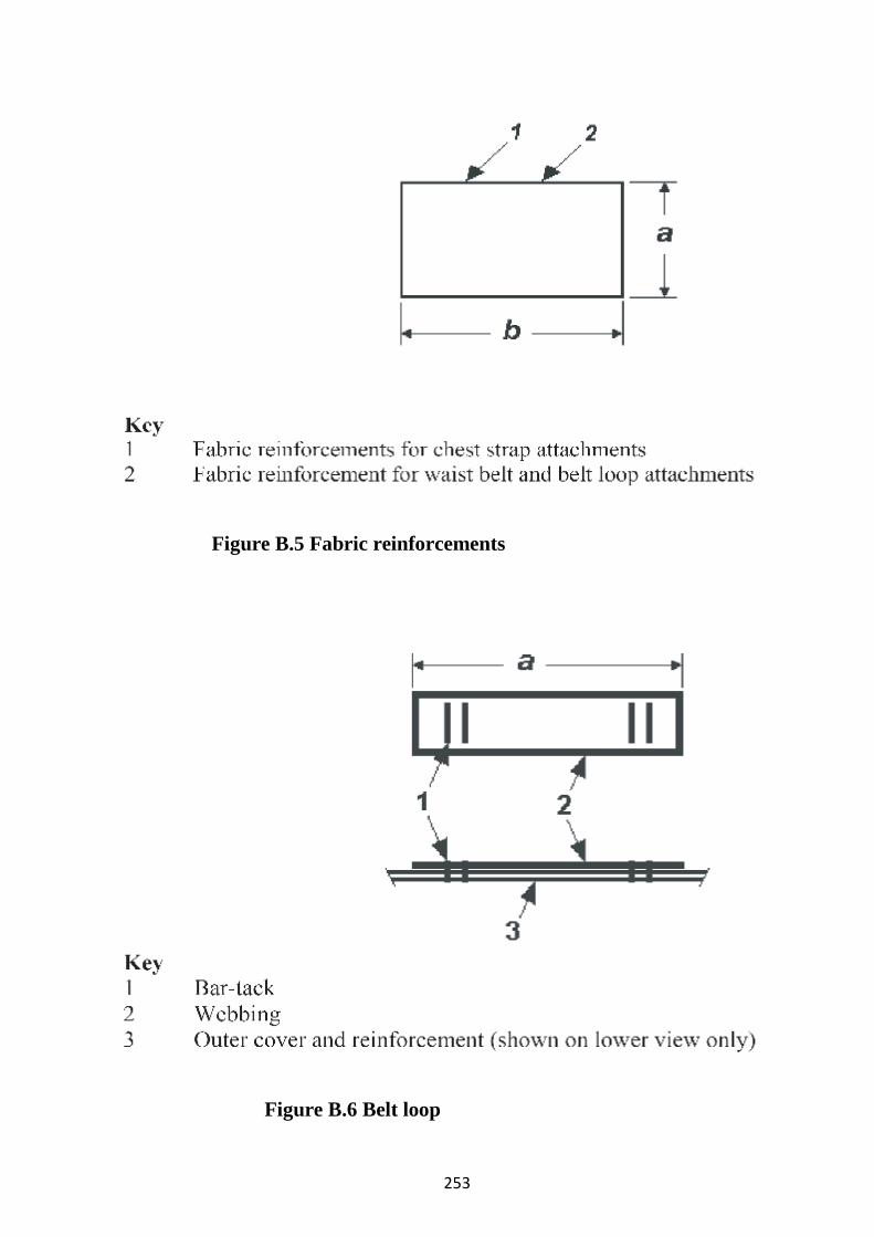
Figure B.5 Fabric reinforcements
Figure B.6 Belt loop
253

Figure B.7 Chest strap assembly (adjustable part left and fixed part right)
Figure B.8 Waist belt assembly
254

Figure B.9 Initial assembly (shown right side out, except as noted)
255

Appendix Child Reference Test Device - Buoyancy Tracking and Verification To achieve repeatability in human subject and manikin testing, the overall buoyancy and distribution of buoyancy between the front and back of the RTD should be maintained within a tight tolerance as specified in Table 1.
Table 1 SOLAS child RTD buoyancy and tolerance
Limit / Units Front
buoyancy(1) (2)
Back
buoyancy(1)
Total
buoyancy(1)
Buoyancy
distribution(3)
Design / N 63 25 88 71.5% in front
Maximum / N 65.4 26.2 91.6 73% in front
Minimum / N 60.6 23.8 84.4 70% in front
(1) Values at or corrected to standard temperature and pressure.
(2) The left-to-right buoyancy distribution in the front inserts is to be within 1.3 N of
each other.
(3) Buoyancy distribution is calculated by dividing the front buoyancy by the total
buoyancy.
The buoyancy of a new RTD may exceed the allowable tolerance range until the
normal shrinkage or compression of the foam inserts stabilizes. Until the buoyancies
of the foam inserts have stabilized, buoyancy and distribution should be checked at
regular intervals (perhaps weekly), and then at least monthly thereafter or whenever
used for testing, whichever is longer (frequent use may require more frequent
checks). Only RTD's with buoyancies within tolerance should be used for
certification testing. A data sheet to document the buoyancy and buoyancy
distribution of the RTD is attached.
To check buoyancy tolerances, foam inserts need to be removed from the device.
Take care that all trapped air is removed when checking buoyancy and that layers are
maintained in their proper sequence when reinstalled (considerable effort would be
needed to remove entrapped air if testing the intact device).
Adjustment of buoyancy: At the time of manufacture the left-to-right distribution
256

of buoyancy in the front inserts was adjusted to be within 1.3 N of each other. To
achieve this tolerance, the layers were individually selected to achieve the
cumulative insert buoyancy. If buoyancy of a new device exceeds the upper limits,
one layer per compartment may be altered or replaced to bring the unit into
compliance. The test house may need to add make-up layers (see figure 3) from time
to time to maintain the front-to-back and side-to-side insert tolerances. If the front
buoyancy is under the minimum value, measure the buoyancy of the right and left
sides so that the proper distribution of buoyancy (no more than a 1.3 N difference)
between the right and left front panels can be maintained.
Table 2 SOLAS child RTD insert design buoyancies
Combined left front
insert (13 layers)
Combined right front
insert (13 layers)
Combined back insert
(11 layers)
Design (N) 31.5 31.5 25
S/N ____ Date:
RTD Buoyancy Data Sheet
RTD Serial number/identification: _________________
Date Left front buoyancy
(N)
Right front
buoyancy (N)
Total front
buoyancy (N)
Total back
buoyancy (N)
Total buoyancy
(N)
Buoyancy distribution
(% in front)
Remarks
*Left and right front buoyancy need not be checked if distribution is within tolerance.
*If the temperature and pressure at the time of measurement is not at standard conditions, these
values should be corrected to standard temperature and pressure.
257

Figure 1 Front foam insert specifications
258

Figure 2 Back foam insert specifications
Figure 3 Child RTD “make- up” foam insert sizes
259

Annex 3
Infant Reference Test Device (RTD)
Design and Construction
1 General
The RTD is intended for use only as a test reference standard to represent the desired level of in-water performance of a lifejacket required by the 1974 SOLAS Convention, and is not considered representative of any other required lifejacket performance. The infant RTD is for persons weighing less than 15 kg, or less than 100 cm in height. The device is designed to fit persons with a chest size of less than 50 cm. This RTD is made with layers of buoyant foam in a bib-style design using a heavy nylon shell cover fabric secured to the body with a waist belt with quick and positive closure and adjustment, along with a chest strap at the neck for closure and adjustment. The shell is made with slide fasteners (zippers) in place of closing seams to hold the foam within, in order that the foam inserts can be easily removed to check their buoyancy and renew or supplement them if they are out of tolerance. The RTD is designed to be reasonably comfortable to wear as a non-reversible device.
2 Materials
All materials used should comply with ISO 12402-7.
2.1 Foam requirements
The performance of the RTD is dependent on using plastic foam of the proper stiffness, shapes, and buoyancy.
2.1.1 Stiffness
The buoyant inserts are made of layers of medium stiffness foam to create a flexible but firm buoyancy element.
2.1.2 Shape
The shape of each foam layer is identified in figures C.2 and C.3. Dimensions are in tables C.1, C.2 and C.3.
260

2.1.3 Buoyancy
The total design buoyancy of the device is 71 N. Table C.4 identifies foam characteristics, the buoyancy for each insert and its tolerances, and the overall buoyancy distribution to be verified when using the RTD for certification testing.
2.2 Other component requirements. See table C.1.
3 Construction
The construction and assembly of the device should be in accordance with tables C.1 and C.5 and figures C.1 to C.9. A tolerance of ± 6 mm is used throughout for fabric cutting and stitching assembly. A tolerance of ± 6 mm is also used for foam cutting, however, the buoyancy requirements of table C.4 should be met.
3.1 Seams
Seam allowances are 13 mm, unless otherwise specified. All structural seams use a lock type stitch so that the seam will not unravel when a force is applied in the direction of the seam on any of the threads forming the stitch. Stitching should have a density of 7 - 12 stitches per 25 mm of stitch length. Box-x stitching on the webbing is 30 × 15 mm for the waist belt and 15 × 13 mm for the belt loop and chest strap, unless otherwise specified. The bar-tack stitching on webbing is 30 × 2 mm for the waist belt and 15 × 2 mm for the belt loop and chest strap.
3.1.1 The fabric reinforcements for the waist belt, belt loop and chest strap should be attached to the inside surface of the outside cover before attaching any of these items. On the closing seam of the top and bottom sections of the outside and inside cover, the cut ends of the fabric are turned under and stitched when installing the zippers so that the fabric will not ravel and so that the folds are flush with the line where the zipper teeth mesh (zippers installed to be hidden by cover fabric when closed).
261

Table C.1 Parts, quantity and assembly
Component Description Quantity See figure
Construction notes
1 Cover fabric
420 denier nylon, with ravel resistant coating, orange
C.1, C.4, and C.9
1.1 Outside cover
1 C.1, C.4, and C.9
1.2 Inside cover
1 C.1, C.4, & C.9
1.3 Fabric reinforcement, chest strap
2 C.5 and C.9
Attach one each to inside left and right outside covers for the chest strap. Use lock stitches on three sides each (see figure C.9 for locations).
1.4 Fabric reinforcement, belt and belt loop
2 C.5 and C.9
Attach to inside left and right outside covers for the waist belt and belt loop. Use lock stitches on three sides (see figure C.9 for location).
2 Foam 7 mm thickness, polyethylene (PE) foam, except for one layer as needed to achieve required buoyancy
C.2 and C.3
Layers stacked per Figures C.2 and C.3.
2.1 Front foam insert, left
15 layers
C.2 Trim corners per figure C.2, except outside layers B to G.
2.2 Front foam insert, right
15 layers
C.2 Trim corners per figure C.2, except outside layers B to G.
2.3 Back foam insert
12 layers
C.3
3 Webbing All cut ends heat-sealed.
262

Table C.1 Parts, quantity and assembly
Component Description Quantity See figure
Construction notes
3.1 Waist belt webbing
38 mm, black, polypropylene, with easy adjustment and no significant slippage when used with the specified hardware.
1,085 mm cut length
C.1, C.8 and C.9
On left side attach waist belt with female buckle. Tab on the end of belt formed by turning under 40 mm of material twice and stitching 19 mm from the end of the fold with a bar-tack stitch. For location see figure C.9.
3.2 Belt loop webbing
19 mm, black, polypropylene.
80 mm cut length
C.1, C.6, and C.9
Attach webbing to front outside cover with two sets of double bar tack stitches to form a belt loop. For location see figure C.9.
3.3 Chest strap webbing
19 mm, black, polypropylene.
235 mm and 80 mm cut length
C.1, C.7 and C.9
Attach webbing with female buckle to right outside cover. Attach webbing with male buckle to left outside cover. For location see figure C.9. Tab formed 75 mm from the free end of the male section of chest strap by folding in "Z" pattern 30 mm apart and stitching 15 mm from the fold with a bar-tack stitch. See figure C.7.
4 Thread Generic synthetic AR 5 Hardware 5.1 Buckle 38 mm, plastic (male and
female sections) 1 C.1 and
C.8 Used in waist belt assembly.
5.2 Buckle 19 mm, plastic (male and female sections)
1 C.1 and C.7
Used in chest strap assembly
5.3 Zipper 350 mm, plastic (zipper chain length)
1 C.1 and C.9
Installed to be hidden by cover fabric when closed.
5.4 Zipper 180 mm, plastic separating (zipper chain and box/pin length)
2 C.1 and C.9
Installed to be hidden by cover fabric when closed.
263

Table C.2 List of dimensions shown in figure C.2
Dimension Insert layer dimensions (mm) A B C D E F G
a 140 133 127 120 108 95 83 b 190 184 178 172 165 160 140 c 28 28 28 28 28
Table C.3 List of dimensions shown in figure C.3
Dimension Insert layer dimensions (mm) A B C D E
a 310 303 290 275 255 b 165 160 140 120 95 c 3 3 3 3 -3* R 44 44 44 44 44 * measured in direction opposite to that shown in figure.
Table C.4 Foam insert specifications
Left front insert Right front insert Back insert Density 29 ± 5 kg/m3 29 ± 5 kg/m3 29 ± 5 kg/m3 Compressive strength at 25% (ISO 3386-1)
35 ± 10 kPa 35 ± 10 kPa 35 ± 10 kPa
Buoyancya, b 21 ± 1.2 N 21 ± 1.2 N 29 ± 1.2 N a The buoyancy of most foams will change over time with the greatest change occurring in the first several months after manufacture. The exact kind of foam selected will need to be evaluated to determine the amount of additional buoyancy needed at the time of manufacture to achieve the values specified. bBuoyancy distribution: 59.2 % front ± 1.5 percentage points
264

Table C.5 List of dimensions shown in figures C.4 - C.9
Dimension
Dimensions (mm) Figure C.4
Figure C.5 Key-2
Figure C.6
Figure C.7
Figure C.8 Key-1
Figure C.9
A 390 75 80 75 90 950* 45 B 195 105 110 40 115 C 85 140 D 220 45 E 245 25 F 241 33 G 482 95 H 260 25 I 490 160 * With webbing assembly fully extended.
Figure C.1 General arrangement, right side out (outside and inside)
265

Figure C.2 Front foam inserts (right and left sides)
Figure C.3 Back foam insert
266

Figure C.4 Cover cut pattern (outside and inside covers)
Figure C.5 Fabric reinforcements
267

Figure C.6 Belt loop
Figure C.7 Chest strap assembly (adjustable part left and fixed part right)
268

Figure C.8 Waist belt assembly
269

Figure C.9 Initial assembly (shown right side out, except as noted)
270

Appendix Infant Reference Test Device - Buoyancy Tracking and Verification
To achieve repeatability in human subject and manikin testing, the overall buoyancy
and distribution of buoyancy between the front and back of the RTD should be
maintained within a tight tolerance as specified in Table 1.
Table 1 SOLAS infant RTD buoyancy and tolerance
Limit / Units Front buoyancy(1) (2)
Back buoyancy(1)
Total buoyancy(1)
Buoyancy distribution(3)
Design / N 42 29 71 59.2% in front Maximum / N 44.4 30.2 74.6 60.7% in front Minimum / N 39.6 27.8 67.4 57.7% in front (1) Values at or corrected to standard temperature and pressure. (2) The left-to-right buoyancy distribution in the front inserts is to be within 1.3 N of each other. (3) Buoyancy distribution is calculated by dividing the front buoyancy by the total buoyancy.
The buoyancy of a new RTD may exceed the allowable tolerance range until the
normal shrinkage or compression of the foam inserts stabilizes. Until the buoyancies
of the foam inserts have stabilized, buoyancy and distribution should be checked at
regular intervals (perhaps weekly), and then at least monthly thereafter or whenever
used for testing, whichever is longer (frequent use may require more frequent
checks). Only RTDs with buoyancies within tolerance should be used for
certification testing. A data sheet to document the buoyancy and buoyancy
distribution of the RTD is attached.
To check buoyancy tolerances, foam inserts need to be removed from the device.
Take care that all trapped air is removed when checking buoyancy and that layers are
maintained in their proper sequence when reinstalled (considerable effort would be
needed to remove entrapped air if testing the intact device).
Adjustment of buoyancy: At the time of manufacture the left-to-right distribution
of buoyancy in the front inserts was adjusted to be within 1.3 N of each other. To
achieve this tolerance, the layers were individually selected to achieve the
cumulative insert buoyancy. If buoyancy of a new device exceeds the upper limits,
one layer per compartment may be altered or replaced to bring the unit into 271

compliance. The test house may need to add make-up layers (see figure 3) from time
to time to maintain the front-to-back and side-to-side insert tolerances. If the front
buoyancy is under the minimum value, measure the buoyancy of the right and left
sides so that the proper distribution of buoyancy (no more than a 1.3 N difference)
between the right and left front panels can be maintained.
Table 2 SOLAS infant RTD insert design buoyancies Combined left front
inserts (15 layers)
Combined right front
inserts (15 layers)
Combined back inserts
(11 layers)
Design (N) 21 21 29
S/N ____ Date:
RTD Buoyancy Data Sheet
RTD Serial number/identification: _________________ Date Left front
buoyancy (N)
Right front buoyancy (N)
Total front buoyancy (N)
Total back buoyancy (N)
Total buoyancy (N)
Buoyancy distribution (% in front)
Remarks
* Left and right front buoyancy need not be checked if distribution is within tolerance. * If the temperature and pressure at the time of measurement is not at standard conditions, these values should be corrected to standard temperature and pressure.
272

Figure 1 Front foam insert specifications
273

Figure 2 Back foam insert specifications
Figure 3 Child RTD "make-up" foam insert sizes
274

guidance evaluation, testing and acceptance of prototype novel life-saving appliances and arrangements 1 General Provisions 1.1 Purpose This guideline prescribes the appliance and arrangement criteria which should be taken into account and prototype tests which should be carried out for the evaluation of novel designs for international acceptance through the amendment procedure of the Convention. 1.2 Application 1.2.1 This guideline applies to all prototype novel life-saving appliances and arrangements for which provisions have not been made in chapter III of the Convention, as amended.
1.2.2 The provisions of this guideline should be applied when introducing equivalent life-saving appliances and arrangements pursuant to regulation I/5 of the Convention . 1.3 Definitions 1.3.1 The appropriate terms and definitions given in regulations I/2 and III/3 of the Convention, as amended, also apply to this Code. In addition, for the purpose of this Code unless expressly provided otherwise:
.1 Equivalent means a particular fitting, material, appliance, apparatus or arrangement, or any combination of fittings, materials, appliances, apparatus or arrangements allowed by an Administration to be fitted or carried in a ship in substitution for any of the requirements of chapter III of the Convention.
.2 Prototype life-saving appliance or arrangement is the first appliance or arrangement produced of a size and construction or performance characteristics differing from previous designs. If an appliance or arrangement is a modification of a previous design, only those characteristics affected by the modification are considered to be prototype characteristics which must be prototype tested. .3 Prototype tests are those tests to which a prototype life - saving appliance or arrangement is subjected in order to test features which
275

cannot be considered by the Administration on the basis of reasonable extrapolation of previous test results or experience. .4 Active survival craft means a survival craft propelled by an engine. .5 Passive survival craft means a survival craft which is not propelled by an engine.
2 General Criteria 2.1 Operational readiness 2.1.1 The life-saving appliances on every ship should, either individually or collectively: .1 be safely stowed and in a state of readiness for immediate use;
.2 provide means of abandonment of all persons on board in the shortest possible time, in the case of:
.2.1 passenger ships, within a period of 30 min; and .2.2 any other ship, within a period of 10 min;
.3 include portable buoyancy equipment f or the support and detection of persons in the water. Such equipment should be:
.3.1 so distributed as to be readily available on both sides of the ship and as far as practicable on all open decks extending to the ship's side; at least one should be placed in the vicinity of the stern; .3.2 stowed in conspicuous places and so that they can be readily cast loose; they should not be permanently secured; and .3.3 fitted with suitable aids to assist detection;
.4 include sufficient individual buoyancy equipment for every person on board and, in addition, sufficient additional equipment to replace equipment which may become inaccessible; .5 provide for the rescue and retrieval of persons in the water from survival craft or distressed ships;
.6 not be rendered inoperable by the effects of the marine atmosphere, seawater, fresh water, oil or fungus; in addition, where exposed to sunlight, they should be resistant to deterioration;
.7 not be damaged in stowage throughout an air temperature range from - 30°C to +65°C and, if they are likely to be immersed in seawater during their use, be capable of operating throughout a seawater temperature
276

range from -1°C to +30°C, unless other temperature ranges are relevant; .8 on ships carrying hazardous cargo, provide protection for the crew from the effects of cargo hazards or fire during and after abandonment;
.9 where practicable, be constructed of fire-retardant materials; however, their attachments, fittings or equipment need not be of fire-retardant material provided they do not affect the efficient functioning of the appliance;
.10 be maintained and tested to ascertain that they meet the requirements of this Code.
2.1.2 Descriptions and instructions for operation, inspection, maintenance and functional testing should be provided for all the life-saving appliances, covering as appropriate the:
.1 purpose; .2 operating description; .3 physical description; .4 operating instructions; .5 requirements for inspection, maintenance, replacements and specialist servicing; .6 requirements for operational testing, standards of performance, methods of adjustment; and .7 fault-finding procedures.
2.1.3 Posters and signs in the vicinity of appliances and controls should: .1 indicate the purpose of controls and procedures for operating the appliances or controls and give relevant instructions and warnings; .2 be easily seen under emergency lighting conditions.
2.1.4 Instructions should be provided for each crew member which include the operations to be performed in relation to life-saving appliances in emergencies.
2.1.5 Spares and repair equipment should be provided for life-saving appliances or parts of life-saving appliances which are subject to excessive wear or consumption. 2.1.6 Life-saving appliances should be easy to inspect, maintain and test and, where applicable, be serviced at an approved servicing station.
277

2.1.7 Life-saving appliances should be simple to operate and should be so constructed that crew members can be easily familiarized with their use during practice musters and drills and require minimum prior training or experience.
2.1.8 Survival craft with launching arrangements should be stowed or located so that:
.1 neither the survival craft nor its stowage arrangements will interfere with the operation of any other survival craft or any other launching station;
.2 they are as near sea level as is safe and practicable and the embarkation position is at least 2 m above the waterline with the ship trimmed up to 10° and listed up to 20° either way, in the fully loaded condition, or to the angle at which the ship's weather deck edge becomes submerged, whichever is the least;
.3 boarding and launching can take place: .3.1 in cargo ships, directly from the stowed position and in the case of passive survival craft provided with launching devices, from a position immediately adjacent to the stowed position or from a position to which the survival craft is transferred prior to launching;
.3.2 in passenger ships, either directly from the stowed position or from an embarkation deck but not both and, in the case of passive survival craft provided with launching devices, from a position immediately adjacent to the stowed position or from a position to which the survival craft is transferred prior to launching; .4 they are kept in a state of continuous readiness and so that two crew members can carry out preparations for boarding and for launching in less than 5 min;
.5 after being prepared for boarding, they may be boarded in the case of: .5.1 passenger ships, rapidly; .5.2 cargo ships, in not more than 3 min;
.6 with the exception of that equipment which may be stowed in another location to protect it from pilferage or deterioration, they are fully equipped with all systems and components required for safe operation; .7 when the survival craft are launched by falls or a fall and are not the additional survival craft provided on passenger ships, they are attached
278

to their launching devices or within reach of the lifting hooks unless rapid and efficient means of transfer are provided which will not:
.7.1 be rendered inoperable under the conditions prescribed in paragraph 2.2.1 or by ship motion;
.7.2 reduce the time for preparing and boarding the survival craft prescribed in paragraphs 2.1.8.4 and 2.1.8.5;
.8 if arranged for throw-over launching, unless an adequate capacity of survival craft is available on both sides, the survival craft can readily be transferred for launching on either side of the ship; .9 they are, as far as practicable, in a secure and sheltered position and protected from damage by fire and explosions.
2.1.9 Survival craft embarkation and launching arrangements should provided except for those survival craft which are portable and are:
.1 boarded from a position on deck less than 4.5 m above the waterline in the lightest seagoing condition; or .2 carried in excess of 200% of the number of persons on board.
2.1.10 ̀ Rescue craft should be stowed in such a way that: .1 they are kept in a state of continuous readiness and can be launched within 5 min; .2 neither the rescue craft nor its stowage arrangements will interfere with the operation of any survival craft at any other launching station.
2.1.11 Means for individual abandonment should: .1 enable unassisted descent from deck to the water surface; .2 be stowed in conspicuous and accessible locations ready for use:
.2.1 in the vicinity of survival craft launching areas; and .2.2 in areas where persons may be isolated from survival craft due to fire or explosions.
2.1.12 Facilities should be provided for alerting all persons on board. 2.2 Abandonment Abandonment should be possible:
279

.1 with the ship trimmed up to 10° and listed up to 20° either way or up to such angles of trim or list at which the ship's weather deck edge
becomes submerged, whichever is the least and on oil tankers, chemical tankers and gas carriers with a final angle of heel greater than 20°calculated in accordance with the International Convention for the Prevention of Pollution from Ships, 1973, as modified by the 1978 Protocol relating thereto and there commendations of the Organization* as applicable, at the final angle of heel on the lower side;
.2 with the ship adrift in a seaway; .3 in case of cargo ships of 20,000 gross tonnage and upwards, with the ship making way at speeds up to 5 knots in calm water; .4 without depending upon any means other than gravity or stored power which is independent of the ship's power supplies to launch the survival craft.
2.3 Survival 2.3.1 Survival craft systems should:
.1 provide subsistence and protection for their complement under adverse weather conditions;
.2 have the capability of manoeuvring in a seaway.
2.3.2 Rescue craft should: .1 provide protection for their complement under adverse weather conditions; .2 have the capability of manoeuvring in a seaway.
2.4 Detection
2.4.1 Visual means of detection for survival craft should make it possible:
.1 for an aircraft at an altitude of up to 3,000 m to detect the survival craft at a range of at least 10 miles; and
* Refer to the damage stability requirements of the International Code for the Construction and Equipment of Snip Carrying Dangerous Chemicals in Bulk (IBC Code) (MSC. 4(48),as amended), and the international Code for the Construction and Equipment of Ships Carrying Liquefied Gases in Bulk (IGC Code)(resolution MSC.5(48), as amended).
280

.2 for a ship to detect the survival craft in a seaway in clear conditions at a range of at least 2 miles. 2.4.2 Visual means of detection for persons in the water should make it possible for a ship to detect the person in a seaway:
.1 in clear daytime conditions at a range of at least 0.2 miles; .2 in clear night - time conditions at a range of at least 0.5 miles for a duration of at least 8 h.
2.5 Retrieval
2.5.1 Survival craft should: .1 if passive, be capable of being towed at speeds of up to 3 knots; .2 if active, be capable of being towed at speeds of up to 5 knots and be
capable of towing other survival craft; .3 permit a person to transfer from the survival craft in a seaway to a ship
or helicopter.
2.5.2 Rescue craft should be capable of being towed at speeds of up to 5 knots and be capable of towing a survival craft.
2.5.3 Launching arrangements for rescue craft should provide safe launching from the ship in a seaway with the ship making way at speeds of up to 5 knots.
2.5.4 Retrieval arrangements for rescue craft should permit rapid recovery of the rescue craft with its rescue craft complement of at least six persons and equipment in a seaway. 3 Appliance Criteria and Testing of Prototypes
3.1 Personal life-saving appliances
3.1.1 Buoyancy equipment intended to support and enable detection of persons in the water should:
.1 where required to be fitted with a buoyant lifeline, have a lifeline equal in length to at least twice the height at which it is stowed above the waterline in the lightest seagoing condition, or 30 m, whichever is the greater;
281

.2 be constructed to withstand a drop from the height at which it is stowed above the lightest seagoing waterline, or 30 m, whichever is the greater, without impairing its operating capability or that of its attached components;
.3 be capable of supporting not less than 14.5 kg of iron in fresh water for a period of 24 h;
.4 have means to enable persons to cling to the equipment; .5 not sustain burning or continue melting after being totally enveloped in
a fire for a period of 2 s; .6 where required, be sufficiently heavy to operate release arrangements of
the attached means of detection; .7 be prototype tested with regard to paragraphs 3.1.1.2 to 3.1.1.6;
.8 where required, be provided with means of detection, complying with the requirements of paragraph 3.7.1.
3.1.2 Individual buoyancy equipment should: .1 be so designed that after a demonstration a person can correctly don the equipment within a period of 1 min without assistance; .2 not sustain burning or continue melting after being totally enveloped in a fire for a period of 2 s; .3 be possible to wear without undue discomfort during abandonment and within a survival craft; .4 if inflatable, inflate automatically upon immersion and be capable of being inflated manually and by mouth; .5 if inflatable, perform effectively with any one buoyancy compartment inoperative; .6 allow the wearer to jump into the water from a height of at least 4.5 m without sustaining injury and without dislodging or damaging the equipment; .7 allow swimming and boarding of a survival craft in a seaway; .8 in calm fresh water, be capable of lifting the mouth of a completely relaxed person wearing normal clothing at least 120 mm clear of the water;
282

.9 in calm fresh water, be capable of turning a completely relaxed person wearing normal clothing from any position in the water to one where the mouth is clear of the water within 5 s; .10 have buoyancy which is not reduced by more than 5% after a 24 h period of submersion in fresh water; .11 be prototype tested with regard to paragraphs 3.1.2.1 to 3.1.2.10 and with regard to paragraph 3.1.2.7 in a seaway; .12 be provided with means of detection complying with paragraph 3.7.2; however, equipment provided on passenger ships on short international voyages need not comply with paragraph 3.7.2.2.
3.1.3 Individual garments for protection against hypothermia should: .1 be so designed that after a demonstration a person can without assistance unpack and correctly don the garment and any required additional individual buoyancy equipment and clothing, within a period of 2 min, taking into account possible low ambient temperature conditions; .2 not sustain burning or continue melting after being totally enveloped in a fire for a period of 2 s; .3 not cause undue discomfort to the wearer during abandonment or in survival craft and permit the person wearing it and any additional individual buoyancy equipment and any associated clothing to:
.3.1 perform normal duties during abandonment; .3.2 climb up and down a ladder at least 5 m in length; .3.3 jump vertically into the water from a height of at least 4.5 m without sustaining injury, dislodging or causing damage to the garment or allowing undue ingress of water;
.4 allow a person wearing the garment and any required additional individual buoyancy equipment to swim and board a survival craft in a seaway;
.5 in calm fresh water, in conjunction with any required additional individual buoyancy equipment, be capable of lifting the mouth of a completely relaxed person wearing the garment at least 120 mm clear of the water;
283

.6 in calm fresh water permit a person wearing the garment and any required additional individual buoyancy equipment to turn from any position to one where the mouth is clear of the water in not more than 5 s; .7 if provided with buoyancy, not suffer a loss of buoyancy of more than 5% after a 24 h period of submersion in fresh water; .8 be prototype tested with regard to paragraphs 3.1.3.1 to 3.1.3.7 and with regard to paragraph 3.1.3.4 in a seaway; .9 if meant to be worn without additional buoyancy equipment or on top of such equipment, be provided with means of detection complying with paragraph 3.7.2.
3.1.4 In addition to meeting paragraph 3.1.3, an individual garment for long-term immersion should:
.1 when used over light clothing and with any required additional individual buoyancy equipment, allow the wearer following one jump into the water from a height of 4.5 m to float in calm circulating water of between 0°C and 2°C for a period of 6 h during which period the wearer's body core temperature should not fall more than 2°C. .2 permit the wearer, on completion of the above test, to be able to pick up a pencil and write; ` .3 be prototype tested with regard to paragraphs 3.1.4.1 and 3.1.4.2.
3.1.5 In addition to meeting paragraph 3.1.3, an individual garment for short-term immersion should:
.1 when worn in conjunction with warm clothing and any required additional individual buoyancy equipment, following one jump by the wearer into the water from a height of 4.5 m, continue to provide sufficient thermal protection to ensure that when worn for a period of 1 h in calm circulating water at a temperature of 5°C the wearer's body core temperature should not fall more than 2°C; .2 permit the wearer, on completion of the above test, to be able to pick up a pencil and write; .3 be prototype tested with regard to paragraphs 3.1.5.1 and 3.1.5.2.3.2 Survival craft
284

3.2 Survival craft should: .1 where arranged to be suspended by falls and lowered to the water by means of a launching device, be of sufficient strength to withstand:
.1.1 if rigid, an overload of 100% of the total mass of the survival craft when loaded with its full complement of persons and equipment, without suffering significant residual deflection on removal of that load, except that in the case of a survival craft constructed of metal, the overload should be 25%;
.1.2 if inflatable, a load of 4 times the mass of its full complement and equipment at an ambient temperature of +20°C without pressure relief of inflated compartments, and a load of 1.1 times the mass of its full complement and equipment at an ambient temperature of -30°C;
.1.3 when fully loaded without sustaining damage that would affect its efficient functioning
- a sideways impact against a rigid vertical surface at an impact velocity of at least 3.5 m/s; and - a drop into the water from a height of 3 m;
.2 in the case of a self-righting partially enclosed and totally enclosed survival craft, protect its occupants when subjected to the sideways impact referred to in paragraph 3.2.1.1.3;
.3 if inflatable: .3.1 withstand an inflation test pressure of at least 3 times the working
pressure and be so arranged that the pressure cannot exceed twice the working pressure; and
.3.2 inflate with a non - toxic gas within a period of one min at an ambient temperature between 18°C and 20°C and within a period of 3 min at an ambient temperature of 30°C;
.4 where arranged for free-fall launching, have sufficient strength and diving characteristics to withstand a fall into the sea from the maximum height at which it is designed to be stowed, taking into account unfavourable conditions of trim up to 10° and a list up to 20° either way, without impairing its operating capabilities or causing injury to its occupants;
285

.5 where required to float free, be stowed in such a manner as to permit it to float free from its stowage and break free from the ship in an operational condition when the ship sinks; .6 if inflatable, withstand repeated jumps on to it from a height of at least 4.5 m above the water; .7 be approved for the maximum number of persons it is permitted to accommodate, as decided by practical seating tests afloat and based upon the number of adult persons wearing individual buoyancy equipment who can be seated without in any way interfering with the normal operation of its equipment or means of propulsion; .8 when prepared for a launching, permit its full complement of persons excluding any stretcher cases to board rapidly and in the case of cargo ships in not more than 3 min from the time the instruction to board is given; .9 permit embarkation of stretcher cases; .10 have arrangements to secure it to help the ship by a painter of adequate
strength and of a length equal to at least twice the distance from its stowed position to the lightest seagoing waterline or 15 m, whichever is the greater; .11 in the case of a self-righting partially enclosed or totally enclosed
survival craft, unless capable of operating safely in the upside-down position, have such strength and stability that it is inherently or automatically self-righting when all entrances and openings are closed watertight, all equipment is secured and the full complement of persons are secured to their seats with safety belts;
.12 in the case of a passive survival craft, unless capable of operating safely in the upside-down position, have such sufficient strength and stability that:
.12.1 it is self-righting; or .12.2 it can be readily righted, in a seaway, by one person unassisted;
.13 when fully or partly loaded maintain its operational effectiveness when drifting in a seaway; .14 have sufficient buoyancy to support its full complement even when holed in any one location below the waterline without loss of buoyancy
286

material or other damage, to automatically or inherently attain a position which provides an above-water escape for its occupants;
.15 have a freeboard, measured from the waterline to the lowest opening through which the survival craft may become flooded, of not less than 1.5% of the survival craft's length when loaded with one half of its full complement seated to one side of the centreline;
.16 be provided with effective means for bailing or be self-bailing in a seaway, but self-righting partially enclosed survival craft should be automatically self-bailing in a seaway; .17 provide protection for its complement against wind, rain and spray, adequate ventilation and protection for its complement at all ambient temperatures between -15°C and +30°C; .18 be designed with due regard to the safety of persons on board with regard to slippery or hot surfaces and sharp edges; .19 be possible to manoeuvre; .20 provide means for persons in the water to cling to the survival craft; .21 permit persons to board the survival craft from the water when wearing individual buoyancy equipment;
.22 permit those on board the survival craft, when wearing individual buoyancy equipment, to recover persons from the water without their assistance; .23 be provided with manually controlled lighting sufficient to permit reading of instruction material and to facilitate operations at night with a power capacity sufficient for at least 12 h; .24 carry provisions, water and equipment for the full complement; .25 be of sufficient strength and have sufficiently strong fixtures and painters to be:
.25.1 towed at speeds up to 3 knots in the case of passive survival craft; .25.2 towed at all speeds up to 5 knots in the case of active survival craft; .25.3 launched with the ship making headway at speeds up to 5 knots in the case of active survival craft intended for use on cargo ships of 20,000 gross tonnage and upwards;
287

.26 have means of permitting watertight rest wage, where equipment is required to be stowed in watertight containers; .27 be so arranged that in a seaway, a person in the survival craft may be picked up by helicopter or transferred to a ship by ladder or net without assistance from other persons in the survival craft; .28 be prototype tested with regard to paragraphs 3.2.1.1 to 3.2.1.6, 3.2.1.8 to 3.2.1.12, 3.2.1.14, 3.2.1.15, 3.2.1.17, 3.2.1.19 to 3.2.1.23 and 3.2.1.25 and with regard to paragraphs 3.2.1.7 and 3.2.1.16 in a seaway; .29 be provided with means for location and detection complying with paragraph 3.7.4.
3.2.2 In addition to meeting the requirements of paragraph 3.2.1, active survival craft should:
.1 have a means of propulsion, capable of being started manually or by two independent power sources and operated at an ambient temperature of -15°C within 2 min of commencing the engine start procedure using if necessary starting aids, unless, having regard to the particular voyages in which the ship carrying the craft is constantly engaged, another minimum starting and operating temperature is appropriate; .2 if self-righting partially enclosed or totally enclosed, have a means of propulsion capable of running in the inverted position during capsize of the survival craft and of continuing to run after returning to the upright position unless it is stopped automatically when inverted and is easily restarted after the survival craft has returned to the upright position and, in the case of a self-righting partially enclosed survival craft, the water has drained from the survival craft. Capsizing should not cause a significant spill of oil into the survival craft; .3 have sufficient mobility and manoeuvrability in a seaway to allow retrieval of persons from the water, marshalling of passive survival craft and to allow the largest passive survival craft carried on the ship to be towed at a speed of 2 knots in calm water; .4 be capable of maintaining a speed of at least 6 knots for at least 24 h; .5 be designed with due regard to the safety of persons in the water and the possibility of damage to the propulsion system by floating debris;
288

.6 be prototype tested with regard to paragraphs 3.2.2.1, 3.2.2.2 and 3.2.2.4 and with regard to paragraph 3.2.2.3 in a seaway.
3.2.3 In addition to meeting the requirements of paragraphs 3.2.1 and 3.2.2, a survival craft with a self-contained air support system should: .1 be capable of proceeding at maximum power for at least 10 min without exposing its complement to harmful gases or creating a sub atmospheric pressure within the survival craft; .2 be prototype tested with regard to paragraph 3.2.3.1 by running the survival craft for at least 10 min while maintaining an overpressure within the survival craft of not more than 20 mbar.
3.2.4 In addition to meeting the requirements of paragraphs 3.2.1, 3.2.2 and 3.2.3, fire-protected survival craft should be prototype tested by enveloping the survival craft with its means of propulsion running in a fire for a period of at least 8 min during which time there should be no ingress of harmful fumes and habitable temperatures should be maintained within the survival craft. 3.3 Rescue craft Rescue craft should comply with the provisions of paragraphs 3.2.1.1.1, 3.2.1.4, 3.2.1.11, 3.2.1.13, 3.2.1.15 to 3.2.1.18, 3.2.1.20 to 3.2.1.22, 3.2.1.25.2, 3.2.1.29, 3.2.2.1, 3.2.2.3 and 3.2.2.5, and in addition should:
.1 where arranged to be suspended by a fall or falls and lowered to the water by means of a launching device, be of sufficient strength and fingered to withstand:
.1.1 if inflated, a load of 4 times the mass of the rescue boat and its full complement of persons and equipment at an ambient temperature of 20°C with all relief valves inoperative and 1.1 times the mass of the rescue boat and its full complement of persons and equipment at an ambient temperature of -30°C with all relief valves operative; .1.2 when fully loaded, without sustaining damage that would affect ` its efficient functioning:
- a sideways impact against a rigid vertical surface with an impact velocity of at least 3.5 m/s; and - a drop into the water from a height of 3 m;
289

.2 be capable of carrying at least five persons seated and at least one person lying down;
.3 be approved for the maximum number of persons to be decided by practical seating tests in a seaway and based upon the number of adult persons wearing individual buoyancy equipment who can be seated without in any way interfering with the normal operation of its equipment or means of propulsion;
.4 when preparing for launching, permit its full complement of persons, excluding any stretcher cases, to board in not more than 3 min; .5 have sufficient buoyancy and stability to support its full complement even when holed in any one location and open to the sea; .6 offer protection against exposure to sea spray; .7 be capable of maintaining a speed of at least 6 knots for at least 4 h in a seaway; .8 be prototype tested with regard to paragraphs 3.2.1.1.1, 3.2.1.4, 3.2.1.16, 3.2.1.22, 3.2.2.1, 3.2.2.3, 3.3.1.1, 3.3.1.2, 3.3.2 to 3.3.4, 3.3.6 and 3.3.7 and with regard to paragraphs 3.2.1.11, 3.2.1.13, 3.2.1.18, 3.2.1.20, 3.2.1.25.2, 3.2.1.29, and 3.3.5 in a seaway.
3.4 Launching arrangements 3.4.1 Launching arrangements for survival craft should: .1 provide safe launching under normal conditions and with the ship trimmed up to10° and listed up to 20° either way or up to such angles of trim or list at which the ship's weather deck edge becomes submerged, whichever is the least, and on oil tankers, chemical tankers and gas carriers with a final angle of heel greater than 20° calculated in accordance with the International Convention for the Prevention of Pollution from Ships, 1973, as modified by the 1978 Protocol relating thereto and the recommendations of the Organization* as
applicable, at the final angle of heel on the lower side; .2 in the case of cargo ships of 20,000 gross tonnage and upwards, provide safe launching with the ship making headway at speeds of up to 5 knots;
*Refer to the damage stability requirements of the International Code for the Construction and Equipment of Ship Carrying Dangerous Chemicals in Bulk (IBC Code)(MSC.4(48),as amended), and the International Code for the Construction and Equipment of Ships Carrying Liquefied Gases in Bulk (IGC Code)(resolution MSC.5(48), as amended).
290

.3 where they include falls and a winch, ensure that the speed at which the survival craft is lowered into the water is controlled by suitable means and such that the rate of descent after initial acceleration is at least a rate obtained from the formula: where
S = height in metres from the uppermost point of suspension to waterline in the lightest seagoing condition;
.4 meet the requirements of the Administration for the maximum lowering speed of the survival craft to ensure the protection of its occupants from excessive forces and to prevent damage to the launching arrangements taking into account inertial forces during an emergency stop; .5 except for winch brakes, be of sufficient strength to withstand a static load of at least 2.2 times their maximum working load; .6 where they include winch brakes, have winch brakes of sufficient strength to withstand:
.6.1 a static test with a proof load of 1.5 times the maximum working load;
.6.2 a dynamic test with a proof load of not less than 1.1 times the maximum working load at maximum lowering speed;
.7 be capable of being actuated by one person from a position on board the survival craft and from a position on deck from which the launching can be observed and the release of the survival craft from the launching arrangements should be possible from a position on board the survival craft;
.8 if based on launching by a fall or falls, have a release mechanism which will release the survival craft into the water without causing damage to the survival craft;
.9 if for float-free release: .9.1 release the survival craft from its stowed position; .9.2 be designed to minimize the possibility of the survival craft
becoming fouled in davits, cranes, rigging or superstructure; .9.3 not be released unintentionally by such forces as water on deck and
heavy weather; 291

.9.4 not be affected by shipboard vibration; .9.5 provide for manual release; .9.6 of survival craft having a rigid enclosure, release and launch the
survival craft in all conditions of loading without it becoming swamped and should in addition allow the release and launch of the survival craft from the operator's position within the survival craft;
.10 if arranged for free-fall launching, ensure that the survival craft is released clear of the ship;
.11 ensure that the survival craft is upright in the water after launching into a seaway, unless the survival craft is self-righting, may be used in the upside-down condition or can be righted by one person in the water;
.12 be prototype tested with regard to paragraphs 3.4.1.2 to 3.4.1.11 and with regard to paragraph 3.4.1.1 in a seaway. 3.4.2 Launching arrangements for rescue craft should comply with the provisions of paragraphs 3.4.1.3 to 3.4.1.7, 3.4.1.10 and in addition should: .1 provide safe launching when the ship is: .1.1 in a seaway; and .1.2 making headway at speeds of up to 5 knots; .2 if based on launching by a fall or falls, have a release mechanism which
will release the rescue craft into the water without causing damage to the rescue craft or injury to its complement; and
.3 be prototype tested with regard to paragraphs 3.4.1.3 to 3.4.1.7, 3.4.1.10, 3.4.2.1 and 3.4.2.2 and with regard to paragraph 3.4.2.1.1 in a seaway. 3.5 Retrieval arrangements 3.5.1 Retrieval arrangements for active survival craft should:
.1 provide for safe retrieval of the survival craft in a seaway; .2 return the survival craft to its position of stowage and readiness for use; .3 be of sufficient strength to withstand a static load of at least 2.2 times its working load except for winch brakes which should withstand a static load of 1.5 times the maximum working load;
292

.4 be prototype tested with regard to paragraphs 3.5.1.2 and 3.5.1.3 and with regard to paragraph 3.5.1.1 in a seaway.
3.5.2 Retrieval arrangements for rescue craft should: .1 provide for safe retrieval of the craft in a seaway; .2 provide a retrieval speed of at least 0.3 m/s when loaded with its rescue craft complement of at least six persons and equipment; .3 return the craft to its position of stowage and readiness for use;
.4 be of sufficient strength to withstand a static load of at least 2.2 times its working load except for the winch brakes which should withstand a static load of 1.5 times the maximum working load; `.5 be prototype tested with regard to paragraphs 3.5.2.2 to 3.5.2.4, and
with regard to paragraph 3.5.2.1 in a seaway.
3.6 Means of passing a line 3.6.1 Means of passing a line from the ship should:
.1 be capable of throwing a line with reasonable accuracy over a distance of at least 230 m; and .2 be prototype tested with regard to paragraph 3.6.1.1.
3.7 Communications (alerting and detection) 3.7.1 Buoyancy equipment intended to support and enable detection of persons in the water should:
.1 if required, have active means of detection attached which is automatically activated when the buoyancy equipment is released and makes it possible to detect the buoyancy equipment in a seaway visually from a ship at a range of at least 1 mile for a period of:
.1.1 at least 15 min under clear daytime conditions; and .1.2 at least 2 h under clear night-time conditions; and when carried on tankers, such active means of detection should be of a type which cannot cause ignition of flammable vapours;
.2 have passive means of detection which makes it possible to detect the buoyancy equipment in a seaway visually from a ship at a range of at least 0.3 miles under clear daytime conditions and, when illuminated by
293

a searchlight, from a range of at least 0.3 miles under clear night-time conditions;
.3 identify the ship on which it is carried; .4 be prototype tested with regard to paragraph 3.7.1.1 and with regard to paragraphs 3.7.1.1.1, 3.7.1.1.2 and 3.7.1.2 in a seaway.
3.7.2 Individual buoyancy equipment and garments for protection against hypothermia should:
.1 have a manually controlled active means of detection which makes it possible to detect a person in a seaway audibly at a range of at least 0.2 miles in calm weather; .2 have active means of detection which makes it possible to detect a person in a seaway visually at a range of at least 0.5 miles under clear night-time conditions for a period of not less than 8 h; .3 have passive means of detection which makes it possible to detect a person in a seaway visually from a ship at a range of at least 0.2 miles under clear daytime conditions and, when illuminated by a searchlight, from a range of at least 0.2 miles under clear night-time conditions; and
.4 be prototype tested with regard to paragraph 3.7.2.1 and with regard to paragraphs 3.7.2.2 and 3.7.2.3 in a seaway.
3.7.3 Survival craft should: .1 have active means of detection which makes it possible to visually locate or detect the survival craft in a seaway from a ship or an aircraft, as appropriate:
.1.1 at an altitude of 3,000 m at a range of at least 10 miles under clear daytime and night-time conditions for a period of at least 40 s; .1.2 at a range of at least 3 miles under clear night-time conditions for a period of at least 1 min; .1.3 at a range of at least 2 miles under clear daytime conditions for a period of at least 3 min; .1.4 at a range of at least 2 miles under clear night-time conditions, which means should be manually operated, have sufficient capacity for at least 12 h operation and, in the case of passive survival craft, should be automatically activated when launched;
294

.2 have passive means of detection which makes it possible to locate and detect the survival craft in a seaway visually from a ship at a range of at least 1 mile in clear daytime conditions and, when illuminated by a searchlight, under clear night-time conditions; .3 identify the ship on which they are carried; .4 be provided with items that are prototype tested with regard to paragraphs 3.7.3.1 and 3.7.3.2 in a seaway.
3.7.4 Rescue craft should: .1 have active means of detection which makes it possible to detect the rescue craft in a seaway from the ship on which they are carried, visually at a range of at least 2 miles under clear daytime and night-time conditions; .2 have passive means of detection which makes it possible to detect the rescue craft in a seaway visually from the ship on which they are carried at a range of at least 1 mile under clear daytime conditions and, when illuminated by a searchlight, under clear night-time conditions; .3 identify the ship on which they are carried; .4 be provided with items that are prototype tested with regard to paragraphs 3.7.4.1 and 3.7.4.2 in a seaway.
3.7.5 The ship should be provided with active means of detection which makes it possible to detect and locate the ship from an altitude of at least 3,000 m at a range of at least 10 miles under clear daytime and night-time conditions for a period of at least 40 s.
295

( Form E ) Record No: xxx/yy
Gross Tonnage IMO Number
Deadweight of ship (metric tons) 1)
Length of ship (regulation III/3.12)
Type of ship 2) : Bulk carrierOil tanker /Chemical tanker /Gas carrier /Cargo ship other than any of the above
an alteration or modification of a major character was commenced.
THIS IS TO CERTIFY:
1
2 That the survey showed that:2.1 the ship complied with the requirements of the Convention as regards fire safety systems and appliances and fire control plans;2.2
2.3
2.4
2.5
2.6 in all other respects the ship complied with the relevant requirements of the Convention.2.7
2.8
3 That the ship operates in accordance with regulation III/26.1.1.13) within the limits of the trade area 4 That in implementing regulation I/6(b) the Government has instituted: Mandatory Annual Survey / Unscheduled Inspection2).5 That an Exemption Certificate has / has not 2) been issued.
This Certificate is valid until
Completion date of the survey on which this certificate is based :
Issued at on
_____________________________
1) For oil tankers, chemical tankers and gas carriers only2) Delete as appropriate
3)
is / is not2) appended to this Certificate. a Document of approval of alternative design and arrangements for fire protection/life-saving appliances and arrangements2)
Date on which the keel was laid or ship was at a similar stage of construction or, where applicable, date on which work for a conversion or
(Place of isssue of certificate) (Date of issue)
Certificate No: YGN/SEC/xxx-yy
under the authority of the Government of
INTERNATIONAL CONVENTION FOR THE SAFETY OF LIFE AT SEA, 1974,
Port of Registry
the ship was provided with a line-throwing appliance and radio installations used in life-saving appliances in accordance with the requirements of the Convention;
the life-saving appliances and the equipment of the lifeboats, liferafts and rescue boats were provided in accordance with the requirements of the Convention;
Director General
Page 1 of 2
CARGO SHIP SAFETY EQUIPMENT CERTIFICATEThis Certificate shall be supplemented by a Record of Equipment for Cargo Ship Safety ( Form E )
Issued under the provisions of the
as modified by the Protocol of 1978 relating thereto
the ship complied with the requirements of the Convention as regards shipborne navigational equipment, means of embarkation for pilots and nautical publications;the ship was provided with lights, shapes and means of making sound signals and distress signals in accordance with the requirements of the Convention and the International Regulations for Preventing Collisions at Sea in force;
THE REPUBLIC OF THE UNION OF MYANMAR
Name of Ship
Department of Marine Administration
Distinctive Number or Letters
the ship was/was not 2)subjected to an alternative design and arrangements in pursuance of regulation(s) II-2/17 / III/382) of the Convention;
Refer to the 1983 amendments to SOLAS(MSC.6(48)), applicable to ships constructed on or after 1 July 1986, but before 1 July 1998 in the case of self-righting partially enclosed lifeboat(s) on board.
That the ship has been surveyed in accordance with the requirements of regulation I/8 of the Convention as modified by the 1978protocol.
by DEPARTMENT OF MARINE ADMINISTRATION

Mandatory Annual Survey2),5) / Unscheduled Inspection2)
(Signature of authorized official)
********
2) Delete as appropriate
4)
5)
Record No. xxx-yy
(for tankers of 10 years of age and over)
(Seal or stamp of the Authority, as appropriate)
(Seal or stamp of the Authority, as appropriate)
(Seal or stamp of the Authority, as appropriate)
Certificate No: YGN/SEC/xxx-yy
Signed: _______________________________________
Place: ____________________________________
Date: ___________________________________
Signed: _______________________________________
Place: ____________________________________
Date: ___________________________________
MANDATORY ANNUAL SURVEYS OR UNSCHEDULED INSPECTIONS
This is to certify that the ship has been surveyed in accordance with regulation I/6(b) of the Convention, as modified by the 1978 Protocol
and the relevant recommendations of the Organization.4)
Signed: _______________________________________
Under the provisions of regulation I/14 of the Convention, as modified by the 1978 Protocol, the validity of this Certificate is extended until ___________________
Reference is made to Guidelines on surveys required by the 1978 SOLAS Protocol, the International Bulk Chemical Code and the International Gas Carrier Code adopted by the Organization by resolution A. 560(14). as amended by MSC.84(70), and applicable parts of the Survey Guidelines under Harmonized System of Survey and Certification (HSSC), 2011,as may be amended, adopted by the Organization by resolution A.1053(27).
An intermediate survey, but not an unscheduled inspection, may take place of a mandatory annual survey.
Place: ____________________________________
Date: ___________________________________
Page 2 of 2
INTERMEDIATE SURVEY
This is to certify that at an intermediate survey required by regulation I/8 of the Convention, as modified by the 1978 Protocol, this ship was found to comply with relevant provisions of the Convention.
(Signature of authorized official)
(Signature of authorized official)

Page 1 of 3
1
Name of ship
Distinctive number or letters
2 Details of life-saving appliances
1
Port side Starboard side
2 - -
2.1 - -
2.2 Number of Self-righting partially enclosed lifeboats (regulation III/43)1) - -
2.3 - -2.4
- -
2.5 - -
2.6
2.6.1 - -
2.6.2 - -
2.7 Number of free-fall lifeboats
2.7.1
2.7.2
2.7.3
3
3.1
4
4.1
5
5.1
5.1.1
5.1.2
5.2
5.2.1
5.2.2
5.3
6
7
8
8.1
8.2
1) Refer to the 1983 amendments to SOLAS (MSC 6(48)), applicable to ships constructed on or after 1 July 1986,but before 1 July 1998.
Record No.xxx-yy
Page 2 of 3
-
-
Liferafts
RECORD OF EQUIPMENT FOR COMPLIANCE WITH
THE INTERNATIONAL CONVENTION FOR THE SAFETY
OF LIFE AT SEA,1974, AS AMENDED
-
Number of motor lifeboats (included in the total lifeboats shown above)
Other lifeboats
-Number of rescue boats
Totally enclosed (regulation III/31 and LSA Code, section 4.7)
-
-
Total number
-
Type
Particulars of ship
Total number of persons accommodated by them
Number of lifebuoys -
Number of lifejackets -
-
Immersion suits
-
Number of persons accommodated by them
Number of liferafts
Number of lifeboats fitted with searchlights
Number of liferafts
Those for which approved launching appliances are not required
-
-Number of liferafts required by regulation III/31.1.4
-
Number of suits complying with the requirements for lifejackets
Total number of persons for which life-saving appliances are provided -
Fire-protected (regulation III/31 and LSA Code, section 4.9)
Number of fire-protected lifeboats (regulation III/31 and LSA Code, section 4.9)
Number of totally enclosed lifeboats (regulation III/31 and LSA Code, section 4.6)
Number of persons accommodated by them
Number
RECORD OF EQUIPMENT FOR CARGO SHIP SAFETY ( Form E )
Number of lifeboats with a self-contained air support system (regulation III/31 and LSA Code, section 4.8)
Total number of lifeboats
-
Number of boats which are included in the total lifeboats shown above
Self-contained (regulation III/31 and LSA Code, section 4.8)
-
-
Those for which approved launching appliances are required

2 Details of life-saving appliances (continued)
9 Number of anti-exposure Suits
10
10.1
10.1.1
10.1.2 AIS search and rescue transmitters (AIS-SART)
10.2
3 Details of navigational systems and equipment
1.1
1.2
1.3
1.4
1.5
1.6
1.7
1.8
1.9
2.1
2.2 Back-up arrangements for ECDIS
2.3
2.4
3.1
3.2
3.3
3.4
3.5
3.6
3.7
4.1
4.2
5.1
5.2
6.1
6.2
7
8.1
8.2
9
10
11
2) Alternative means of meeting this requirement are permitted under regulation V/19. In case of other means they shall be specified.
3) Delete as appropriate.
Record No.xxx-yy
Page 3 of 3
Number of search and rescue locating devices
Daylight signalling lamp2)
-
Receiver for a Global navigation satellite system/ terrestrial radio navigation system2),3)
Speed and distance measuring device (over the ground in the forward and athwartships direction)2)
-
-
-
-
-
-
9 GHz radar2)
-
Number of two-way VHF radiotelephone apparatus
-
-
-
-
-
Radio installations used in life-saving appliances
-
-
-
-
-
-
-
Speed and distance measuring device (through the water)2)
Long-range identification and tracking system (LRIT)
-
-
-
-
-
Rate-of-turn indicator2)
Automatic identification system (AIS)
Automatic radar plotting aid (ARPA)2)
Electronic plotting aid2)
Automatic tracking aid2)
Nautical publications
-
-
Second radar (3 GHz / 9 GHz)3),2)
-
-
Rudder, propeller, thrust, pitch and operational mode indicator2)
-
Echo-sounding device2)
-
Gyro-compass heading repeater2)
Simplified voyage data recorder (S-VDR)3)
Telephone to emergency steering position2)
-
Sound reception system2)
Back-up arrangements for electronic nautical publications
-
Voyage data recorder (VDR)3)
Second automatic tracking aid2)
-Nautical charts /Electronic chart display and information system(ECDIS)3)
Heading or track control system2)
Transmitting heading device (THD)2)
Pelorus or compass bearing device2)
Actual Provision
Means of correcting heading and bearings2)
-
Standard magnetic compass2)
Radar search and rescue transponders (SART)
-
Gyro-compass bearing repeater2)
Gyro-compass2)
-
Item
Spare magnetic compass2)

3 Details of navigational systems and equipment (continued)
12
13
14
15
THIS IS TO CERTIFY that this Record is correct in all respects.
Issued at on
_____________________________
2) Alternative means of meeting this requirement are permitted under regulationV/19. In case of other means they shall be specified.
3) Delete as appropriate.
(Place of isssue of certificate) (Date of issue)
Director General
Department of Marine Administration
Bridge navigational watch alarm system (BNWAS)
Radar reflector2)
-International Code of Signals
-
-IAMSAR Manual, Volume III
-