Reprinted from The Official Journal of ISPE PHARMACEUTICAL ... · Engineers, Inc. (CRB) was founded...
42
48 PHARMACEUTICAL ENGINEERING • JULY/AUGUST 2001 Industry Interview An Interview with the Founders of Clark, Richardson & Biskup - ISPE Company of the Year An Interview with the Founders of Clark, Richardson & Biskup - ISPE Company of the Year A Q Q A C The founders of CRB, Doyle Clark (DC), Gerry Richardson (GR), and Jeff Biskup (JB), discuss the changes they have seen in the industry and challenges they see for the future. The interview was conducted by Jeff Odum, ISPE Publications/ Internet Committee Chairperson. C lark, Richardson & Biskup Consulting Engineers, Inc. (CRB) was founded in April, 1984 through the visions of three entrepreneurial-minded engineers who wanted to provide engineering services to the biopharm market differently than they had experienced and with a customer-driven focus. So, in the basement of Gerry Richardson’s home, friends, Doyle Clark and Jeff Biskup, formed what is now a 250-person consulting engineering firm that is heavily focused on the pharmaceutical and biotech industry. • • • Q As a firm that provides engineering services to the pharmaceutical/ biotech industries, what are the sig- nificant changes you have seen in the industry over the past five years? A GR: The biggest change that I have seen is the emergence of biotech as a viable pharmaceutical area and an area where demand for manufactur- ing capacity has been very signifi- cant. This has resulted in an increas- ing number of new products and the resultant demand for reduced time to market for our projects. Another change that I have seen is in the increased capabilities and use of au- tomation in the research and manu- facturing processes. JB: Probably the change with the most impact on our business is the tendency toward faster and faster project delivery. While there has al- ways been a demand to get there faster, the technology boom fueled by high-speed computers and rapidly improving communications ability, has greatly accelerated the rate of change. The industry’s push to get products to market more quickly is driving manufacturers to make sig- nificant process and facility decisions earlier. At the same time, it demands reductions in time spent in engineer- ing and construction. This imposes a tremendous challenge and heightened risks on all involved. • • • Q Of these changes, which have been the most difficult to deal with as a service provider? A JB: Without a doubt, the most diffi- cult to deal with is the speed of project delivery, especially on new products and processes. To complete projects faster, we are forced to make deci- sions earlier and more quickly. It really changes how you think and forces you to reevaluate priorities. GR: I agree. The simultaneous need for speed and flexibility in the plan- ning, design, construction, and start- -up of manufacturing facilities has changed the way we approach our projects in order to provide value to our clients. • • • 2000 ISPE Company of the Year, CRB Consulting Engineers, founders from left to right: Jeff Biskup, Gerry Richardson, and Doyle Clark. Reprinted from The Official Journal of ISPE PHARMACEUTICAL ENGINEERING® July/August, 2001 Vol. 21 No. 4 ©Copyright ISPE 2001
Transcript of Reprinted from The Official Journal of ISPE PHARMACEUTICAL ... · Engineers, Inc. (CRB) was founded...

48 PHARMACEUTICAL ENGINEERING • JULY/AUGUST 2001
Industry Interview
An Interview with the Foundersof Clark, Richardson & Biskup -ISPE Company of the Year
An Interview with the Foundersof Clark, Richardson & Biskup -ISPE Company of the Year
AQ
Q
A
C
The founders ofCRB, DoyleClark (DC),Gerry Richardson(GR), and JeffBiskup (JB),discuss thechanges theyhave seen in theindustry andchallenges theysee for thefuture.
The interviewwas conducted byJeff Odum, ISPEPublications/InternetCommitteeChairperson.
C lark, Richardson & Biskup ConsultingEngineers, Inc. (CRB) was founded inApril, 1984 through the visions of three
entrepreneurial-minded engineers who wantedto provide engineering services to the biopharmmarket differently than they had experiencedand with a customer-driven focus. So, in thebasement of Gerry Richardson’s home, friends,Doyle Clark and Jeff Biskup, formed what isnow a 250-person consulting engineering firmthat is heavily focused on the pharmaceuticaland biotech industry.
• • •
Q As a firm that provides engineeringservices to the pharmaceutical/biotech industries, what are the sig-nificant changes you have seen in theindustry over the past five years?
A GR: The biggest change that I haveseen is the emergence of biotech as aviable pharmaceutical area and anarea where demand for manufactur-ing capacity has been very signifi-cant. This has resulted in an increas-ing number of new products and theresultant demand for reduced time tomarket for our projects. Anotherchange that I have seen is in theincreased capabilities and use of au-tomation in the research and manu-facturing processes.
JB: Probably the change with themost impact on our business is thetendency toward faster and fasterproject delivery. While there has al-ways been a demand to get therefaster, the technology boom fueled byhigh-speed computers and rapidlyimproving communications ability,has greatly accelerated the rate ofchange. The industry’s push to getproducts to market more quickly isdriving manufacturers to make sig-nificant process and facility decisionsearlier. At the same time, it demandsreductions in time spent in engineer-ing and construction. This imposes atremendous challenge and heightenedrisks on all involved.
• • •
Q Of these changes, which have beenthe most difficult to deal with as aservice provider?
A JB: Without a doubt, the most diffi-cult to deal with is the speed of projectdelivery, especially on new productsand processes. To complete projectsfaster, we are forced to make deci-sions earlier and more quickly. Itreally changes how you think andforces you to reevaluate priorities.
GR: I agree. The simultaneous needfor speed and flexibility in the plan-ning, design, construction, and start--up of manufacturing facilities haschanged the way we approach ourprojects in order to provide value toour clients.
• • •
2000 ISPE Company of theYear, CRB Consulting Engineers,founders from left to right: JeffBiskup, Gerry Richardson, andDoyle Clark.
Reprinted from The Official Journal of ISPE
PHARMACEUTICAL ENGINEERING® July/August, 2001 Vol. 21 No. 4
©Copyright ISPE 2001

JULY/AUGUST 2001 • PHARMACEUTICAL ENGINEERING 49
Industry Interview
A
Q
A
Q
AQ
AQ
QA
QA
QA
QAQ Technologies have been rapidly changing, particu-
larly in the bioprocess area. Do you see any particu-lar changes that hold the most promise for the nextfive to ten years?
A GR: Automation and the inclusion of research andmanufacturing into enterprise integration will takeon ever-increasing importance and result in everincreasing quality.
JB: Relative to the engineering business, I believethe continued evolution of design software is aboutready to pay dividends. Integrated design, simula-tion, and CAD software could help solve some of thespeed to market challenges. It also will help reducerisks by producing better quality documents veryquickly.
• • •
Q What issues do you see as being the greatest chal-lenge to the biopharm industry as it continues togrow?
A GR: For some time, adequate manufacturing capac-ity will be one of the greatest challenges. The needto improve research methods and models will con-tinue to be a great challenge; continued incidences ofvery unpleasant surprises in large scale, as well asPhase 3 clinical trials, place access to adequatecapital at risk.
• • •
Q What was the driving force that led you to form CRBmore than 15 years ago, and do you see that stillbeing a driver of your work today?
A DC: The need for highly specialized consulting andengineering services focused upon the special needsof high technology manufacturers. Yes, more thanever.
• • •
Q What are the new design tools that you see beingimplemented that will provide client firms withimproved design methods and how do they specifi-cally relate to the pharmaceutical/biotech indus-tries?
A DC: Electronic tools that make it easy and costeffective to collaborate with any number of stake-holders and to better coordinate the planning, de-sign, construction, and operation of facilities andprocesses. Project teams are becoming very diverseand these tools are becoming increasingly impor-tant in allowing better communication and controlon projects.
• • •
Q What are the key resources that you see necessaryfor success on process-driven projects involvingmanufacturing operations?
A JB: On the Owner’s side, it is important to have akey decision making authority along with peopleknowledgeable in the manufacturing operation aswell as the process technology. That could be oneperson or ten. On the design side, I believe it iscritical to have excellent technical people who com-municate well with operations people. It is alsoobviously very important to have people who under-stand the project needs and objectives and who cancontrol the scope of the project so that those objec-tives are met on schedule and under budget.
• • •
Q Is there a different philosophy for utility-drivenprojects?
A JB: I think no. Whether we are working with utili-ties or process flow streams, we still have to deter-mine how the system relates to our goal of reliabilityand consistently producing quality and safe phar-maceutical products. Fundamentally, the closer weget to the product, the more cautious we get in ourdesign. That is kind of what the Baseline® Guidesare all about. So, if you move upstream in the processand facility, our design effort becomes more tradi-tional Good Engineering Practice.
• • •
Doyle Clark.
©Copyright ISPE 2001

50 PHARMACEUTICAL ENGINEERING • JULY/AUGUST 2001
Industry Interview
QA
AQ
QA
Jeff Biskup.
Q If you could look inside the crystal ball, what do yousee being the industry outlook over the next fiveyears?
A DC: The future looks very healthy. All indicationsare that biotech will become increasingly dominantas a platform for new drugs. We strongly feel thatthis will present numerous opportunities for every-one on our side of the service industry.
JB: It looks to me like the industry will be veryactive during at least the next five years. I think thetransition from treating symptoms to targeting thesource will generate many new drug products. Theevolution of the biotech industry will result in farmore bio-based drugs than chemical based.
• • •
Q As the first engineering design firm to be recognizedby ISPE as the Company of the Year, what do youfeel are the primary qualities that led to the recog-nition of this firm?
A DC: I think sheer numbers and our long time par-ticipation in leadership led to this recognition. Ourcompany is more heavily focused upon the pharma-ceutical and biotechnology engineering business thanvirtually any other engineering firm. We have viewedISPE as THE technical/professional organizationfor us to support and participate in since I firstattended an annual meeting 15 years ago. Sincethen, we have encouraged everyone in our organiza-tion to get involved in and support ISPE.
JB: I think the second reason we were honored isbecause our commitment to ISPE is for the most partselfless. I have always believed that if you focus onthe objective of the mission, the rewards will takecare of themselves.
• • •
Gerry Richardson.
Q Any last thoughts on the industry you serve?
A DC: There are many benefits to successfully servingthe pharmaceutical and biotechnology industry. Theone that stands out for the long term is the feeling ofsatisfaction that we are doing (our small part) some-thing important to increase the quality of life foreveryone on the planet. My kids do not have a clearunderstanding of what I do at work, but they under-stand that medicines help people feel better; theyunderstand that I help make medicine, and I thinkthey are at least a little bit proud of me because ofthat.
©Copyright ISPE 2001

40 PHARMACEUTICAL ENGINEERING • JULY/AUGUST 2001
Airflow Modelling
The Use of Airflow Modelling inthe Design of PharmaceuticalContainment Systems
The Use of Airflow Modelling inthe Design of PharmaceuticalContainment Systems
C
by Andrew Ramsden
This case studydescribes howComputationalFluid Dynamicssoftware wasused to design apharmaceuticalcontainmentsystem.
Introduction
C ontainment systems are an essentialpart of pharmaceutical current GoodManufacturing Practice (cGMP) and
provide a high level of protection for both theprocess operatives and the product being pro-cessed. With currently recommended OperatorExposure Levels (OELs) being quoted in theorder of micrograms for some products andnanograms for others, it becomes apparent thatcareful attention to the design of a given con-tainment device is paramount. Furthermore,the safe and efficient evacuation of potentiallytoxic airborne particles from within the con-tainment system is highly dependent upon theairflow characteristics of the given device.
The above comments generally relate todown-flow (flow-booth) and barrier containment(isolator) technology as typically employed inprocesses where powdered or vaporous prod-ucts are handled manually. These processesinclude product sampling, dispensing, sub-divi-sion, packaging, and other related operations.It is during the handling process that the risksof operator exposure, direct product contamina-tion, and the potential for cross batch productcontaminations are at their greatest. To reducethese risks, the containment devices must beengineered to operate within limits set by thespecified exposure levels for the processes oroperations being undertaken within the con-fines of the containment system.
To achieve these low levels of exposure, wecan exploit the dynamic characteristic of a fluid,and design a system that provides the optimumairflow conditions for efficient and effectiveevacuation of the containment system. The useof airflow modelling techniques during the de-sign stages of a containment system allows theoptimum operating conditions and dimensionalparameters of the device to be explored. Theresulting design should be a system that can bevalidated. One being as close to the optimumoperating condition that may be defined byconsidering any local, physical, or environmen-
tal constraints. Airflow modelling gives the phar-maceutical process engineer the opportunity toassess a proposed containment solution prior tocommissioning a final design. The followingarticle describes, using a case study, how air-flow modelling was used to solve an identifiedcontainment problem. The airflow modellingwas performed using Computational Fluid Dy-namics (CFD) software.
The MicroChargeDevelopment Project
Defining the ProblemThis project was initiated because it becameapparent that pharmaceutical manufacturersrequire a compact and efficient device that canprovide local containment during the chargingof low volumes of product into production reac-tors. This process has typically involved the useof small vessels that are connected to the reac-tor via some form of split valve. This approachprovides the required contained transfer; how-ever, upon removal of the vessel, the two halvesof the split valve frequently become a source oflocal contamination. This is due to a fine film ofproduct residue, often found lodged around theedges of the valve flaps, being dissipated intothe local environment, and hence creating thepotential for product cross-contamination andunsafe OELs.
To counter this problem, a number of valvemanufacturers provide a means to evacuatethis residue by the use of air-blasts and localexhaust systems. This increases the secondarycontainment potential of the given valve byproviding a level of containment suitable for usewith relatively low risk active compounds andexcipients classified as 510microgram/m³ OEL.To further reduce the risk of residual productbeing dissipated into the surrounding environ-ment, a compact and efficient secondary con-tainment device appeared to offer an acceptablesolution. Investigating current methods of pro-viding this secondary containment indicatedthat isolator technology was being used, and
Reprinted from The Official Journal of ISPE
PHARMACEUTICAL ENGINEERING® July/August, 2001 Vol. 21 No. 4
©Copyright ISPE 2001

JULY/AUGUST 2001 • PHARMACEUTICAL ENGINEERING 41
Airflow Modelling
while this method provides a high degree of containment, theisolators are typically large and can present problems ofmobility during their use. It also became apparent that theisolator was typically ‘over-specified’ if products of only 0.5-1microgram/m³ OEL were being handled.
Developing a SolutionPrior to beginning development work on a project such as this,the aims and objectives of the project should be clearly defined.In this case, it was decided to concentrate on providing second-ary containment for the charging of low microgram/m³ OELproducts by use of a local ‘flow-hood.’ The following list high-lights a number of the primary objectives to be met by thedevice:
• secondary containment <1.0mg/m3
• laminar air-flow through the containment chamber
• efficient operation
• self-contained exhaust system
• simple, low maintenance construction
• ease of installation
• suitable for temporary/mobile charging operations
• ease of cleaning, hygienic design
To meet these objectives, attention first was given to producinga mechanical concept model. Overall dimensions, geometry,and methods of construction were proposed that would fulfilthe defined mechanical requirements. Once the basic conceptwas defined, attention was then given to providing the re-quired airflow characteristics. During this second stage, it wasdecided that the project was suited to analysis by the applica-tion of CFD to help predict and assess the flow characteristicsof the proposed device.
CFD is a software tool that is finding increased use duringthe solution of fluid related problems. It has been used by awide range of diverse industry sectors covering areas involvedin cleanroom operations, ventilation systems, and environ-mental pollutant dispersion as well as the more traditionalareas of heat transfer and general fluid mechanics. For thepurpose of this project, CFD allowed the design to be pro-gressed, through a number of iterations, until the optimumsolution was obtained.
The resulting analyses provided information predicting theairflow velocities, system pressures, and turbulence charac-teristics of the proposed device. This information normally canbe obtained by producing accurate prototypes or physicalmodels and subsequently performing tests under simulated oractual operating conditions. This traditional approach to projectdevelopment typically incurs high design costs, leads to ex-tended development times, and subsequently higher marketcosts to the end user. CFD can effectively help to reduce thesecosts and bring solutions to the market with high levels ofconfidence and relatively short development lead times. In thecase of large scale containment solutions involving the move-ment of large volumes of air, as is typically found in suites ofdown-flow booths providing dispensing and packing facilities,
the cost savings can be significant, both to the manufacturer ofthe equipment, and ultimately the end user.
The Development ProcessHaving briefly discussed some of the uses and benefits of CFD,some of the issues that were addressed with CFD during thedevelopment of this containment project will be described.
Design Geometry
Figure 1. Turbulence plot from initial design.Continued on page 42.
The initial concept was to produce a device that could be fitteddirectly to a reactor via a flange, or other connection device, onthe main reactor charging manway. The device would housethe active half of the split valve and provide a flow of air acrossthe face of the valve when the product transfer bottle, whichcarries the passive valve half, is undocked and removed. Thegeometry and internal features are directly associated withthe airflow through the system and can significantly influencethe performance of the containment device. To this end, consid-eration was given to providing for the most efficient flowpossible given the physical and environmental constraintsunder which the device would be operated.
Airflow CharacteristicsThe airflow characteristics are probably the single most impor-tant feature of a containment device, and as a result, thedecision was made to model this project with the aid of CFD.During the modelling process, a number of geometries wereanalyzed and a few surprises were presented with the results.As described previously, the main objectives when designing acontainment device are to provide for consistent airflow andlow turbulence. The turbulence characteristics are particu-larly important since turbulence may cause suspended par-ticles to be held within the body of the device, and hencepresent potential problems with OELs and product crosscontamination. Both of these effects are detrimental to theoverall efficiency of the device and must be controlled andminimized as much as possible. CFD offers a way to assessthese effects at the design stage helping to avoid potentiallycostly mistakes and the manufacture of sub-standard devices.Time to market, development costs, and other associatedoverheads can all be reduced by using airflow modelling
©Copyright ISPE 2001

42 PHARMACEUTICAL ENGINEERING • JULY/AUGUST 2001
Airflow Modelling
techniques in the early stages of the design process.
Internal FeaturesThe term ‘internal feature’ is used here to describe thosefeatures within the confines of the device that may influencethe desired airflow characteristics. Generally, in the context ofcontainment devices, internal features represent obstructionsto the free flow of air through the device and should be avoided.However, in some cases, they may not be easily removed andwe then have to look for ways to reduce any detrimental effectsthat they may be causing. Typically, they are a source ofturbulence, and as previously explained, turbulence is gener-ally an undesirable characteristic.
This is exemplified in the way the analysis suggested thatgeometry changes were required and how these changes wouldresult in the reduction of the magnitude of the local eddiesdownstream of the valve. These geometry changes ultimatelyimproved the extraction efficiency of the device and this degreeof ‘fine-tuning’ would not generally be possible without theinsight of the predicted flow characteristics as suggested by aCFD analysis early in the design stages.
The CFD MethodTo perform a CFD analysis requires the ‘device’ to be modelledin a CAD system. Typically, this can be any CAD packagecapable of exporting the geometry in one of a number ofalternative formats, i.e. STEP, IGES, STL, etc. The geometryis then pre-processed by the CFD package resulting in a solidmodel of the flow domain. This model is then used to applyknown or estimated boundary conditions that will define thecharacteristics of the flow domain. These could take the formof known inlet/outlet pressures or velocities, mass flows throughthe device (often the easiest parameter to set due to availabledesign data in terms of required airflow and volume of thedevice/system), or known or required pressure domains. Infact, a whole array of conditions can be applied from which theanalysis can be initiated. Identifying the relevant conditionsand the mathematical algorithms used by the CFD solver is amatter of some experience and a subject of some conjecture.The science of CFD is incomplete and at best can only providean approximation. This approximation is, however, in themajority of cases, perfectly acceptable for the requirement of
the design engineers.Following the application of the model’s boundary condi-
tions, the model is subjected to a volumetric meshing processthat defines the nodes required to allow the solver to under-take its mathematical computations. Typically, the solvermodel uses a system of up to seven simultaneous equations.Those familiar with the Reynolds Stress Model and the Navier-Stokes equations of continuity will appreciate the computa-tional effort required to solve a typical flow problem. Havingcompleted the application of the boundary conditions and themeshing process, the solver can be run. In terms of computa-tional effort, this process can take from several minutes tomany hours. To put this into perspective, a study undertakenduring the course of this case study consisted of more than400,000 nodes took around 15 hours to solve - and this was ona relatively high specification workstation, (Dual 550MhzCPUs).
Following the completion of the solving process, the resultsof the analysis can be assessed and interpreted from the wealthof both graphical and numerical data available from themajority of mainstream CFD packages. Many of these pack-ages also can generate animated simulations of the flow fieldsand these can give a real insight into the typical operatingcharacteristics of the given system. This is a bonus to adesigner since as it will show, dynamically, areas that mayneed further attention.
How Airflow Modelling Helped the Design ProcessDuring the development of this device, a particular internalfeature became the subject of some controversy. Traditionally,within local extraction hoods, it has been customary to providea perforated screen within the confines of the device. This hasa two-fold function, a) it provides a pressure differentialbetween the main chamber and the exhaust ducting, and b) itprevents large objects from being drawn into the exhaustsystem with potentially harmful effects to filters or fan ele-ments.
This device was originally provided with such a screen thatran around the internal periphery of the containment chamberand was intended to create the appropriate pressure differen-tials. Figure 1 shows that the device was responsible for a very
Figure 2. Improved airflow resulting from design change.
Figure 3. Turbulence plot from the optimized design.
©Copyright ISPE 2001

JULY/AUGUST 2001 • PHARMACEUTICAL ENGINEERING 43
Airflow Modelling
high degree of turbulence, and upon closer inspection, itactually proved to be promoting a reverse flow behind thescreen. This was an undesirable condition, and without the useof airflow modelling techniques, it could have been easilyoverlooked.
Re-modelling the device, and also altering the exhaustoutlet geometry, resulted in the turbulence characteristicsdisplayed in Figure 2. Here, we can immediately see theimprovements, and though there is obviously still some workrequired on the geometry, CFD indicated that positive progresswas being made. A number of design iterations were to followuntil we arrived at the optimum geometry for the givenoperating conditions and local constraints. Figure 3 shows thepredicted turbulence characteristics of the final design. In-spection of the numeric values, shown on the graphical scale,indicates a significant improvement over the original concept.
To confirm that the final turbulence characteristics wouldresult in what should be, essentially, laminar flow, a velocityplot was generated. Figure 4 describes the airflow character-istics in terms of vectors and confirms that the flow through thedevice would be of an efficient nature with no eddies orbackflows that could cause potential problems by holdingcontaminants within the body of the device. Subsequent test-ing of a physical prototype confirmed and validated the CFDpredictions and led to the introduction of a new product to therange of containment solutions offered to the containmentmarket - Figure 5.
The conclusions, following the modelling process, were thatCFD provided an accurate insight in to how the airflow wouldbehave during operation of the device. The technique allowednumerous variations of the device to be quickly assessed andthe best solution identified prior to manufacturing a prototype.It was agreed in later design reviews that the use of airflowmodelling was a valuable technique that would benefit thedevelopment of containment solutions and strategies as thepharmaceutical products being handled become increasinglypotent. It also was found that the technique could identify andquantify flow characteristics in areas that are particularlydifficult to assess in a physical prototype. The reversed flowbehind the perforated screen of this particular device being agood example, and although this project may appear to be of asimplistic nature, it has demonstrated the value of CFD
Figure 4. Velocity vectors.
Figure 5. The resulting containment device.
andairflow modelling when applied on a small scale.
Some Wider Implications of Using CFD and AirflowModellingIt is now recognized that CFD technologies are generallyavailable for use on desktop computer workstations. Theadvances in computer hardware and the availability of suit-able machines have now brought these technologies within thescope of the working engineer. Where we once needed main-frames and massive computing resources, we can now runthese applications alongside typical high-end CAD systems.The potential for performing concurrent engineering can berealized since CFD can be run parallel with the design processand the benefits of reduced design cycle times begin to berealized by both the manufacturers and their clients. Access toCFD and airflow modelling is becoming increasingly wide-spread and a growing number of consultancies now offer CFDanalysis as a service. To further validate the use of CFD, manyuniversities offer advanced courses of study in CFD relatedsubjects and graduates are subsequently available with thenecessary skills to perform meaningful analyses. This is re-sulting in the growth of the CFD community, and as marketcompetition increases, what was once considered an expensivecommodity is now becoming an accepted method of justifyinga proposed design.
Expanding on the uses of CFD, particularly within the areaof pharmaceutical containment, the methods can be used to
©Copyright ISPE 2001

44 PHARMACEUTICAL ENGINEERING • JULY/AUGUST 2001
Airflow Modelling
and put into service in the pharmaceutical manufacturingplants.
The containment and ventilation technology we have be-come familiar with over the last few decades is beginning toreach the end of its useful life. The advent of high potency drugcompounds, responsible for slowly driving the current genera-tion of containment solutions to their limits, has begun tohighlight some of the deficiencies in the existing designs. Thefuture of high-containment solutions therefore appears to relyon the development of equipment that optimizes the flowcharacteristics of the given equipment, and hence provides anefficient, safe, and reliable combination of operating charac-teristics.
Reference to fundamental principles and tables of airflowcoefficients, etc, during the design of containment solutions,can no longer guarantee the levels of performance dictated bythe OELs required to safely handle these highly active com-pounds. World leaders in the formulation of containmentsolutions have recognized this trend and have subsequentlyembarked upon a route of continuous development that re-assesses the integrity of traditional designs against the predic-tions of CFD analyses and their many years of ‘hands-on’experience. Invariably, the results of these analyses offeropportunities to improve upon existing containment technol-ogy, and this innovation is ultimately being passed on to theconsumer. Those who appreciate and take advantage of thevalue of these efforts will be rewarded with equipment thatfulfills their design expectations by providing both a reliableand safe environment for their operations.
References1. Hughes, W., and Brighton, J. (1967). Schaum’s Outline
of Theory and Problems of Fluid Dynamics, Shaum’sOutline Series, United States of America, McGraw Hill.
2. Speziale, C.G. (1991). Analytical Methods for the De-velopment of Reynolds-Stress Closures in Turbu-lence, Annu. Rev. Fluid Mech., Vol. 23, pp. 107-157.
Figure 6. Airflow schematic.
assess the ventilation performance of an entire plant layout,‘what-if’ scenarios can be analyzed and the effects of potentialbreeches in containment can be assessed. CFD technology alsomay allow the engineer to assess levels of airborne contamina-tion by using various methods of ‘particle dispersal modelling’,and hence facilitate the planning of suitable ventilation andefficient containment strategies. There also are methods avail-able for predicting cycle times during the purging of isolatedsystems, i.e. the levels of inert gas concentrations within anenclosure with respect to time. In all, a wide range of applica-tions can be identified that could warrant investigation withthe aid of CFD. The selection of appropriate equipment canhave a significant effect on the overall performance of a givensystem, and in terms of containment equipment, the detailsbecome very important when considering the order of theOELs that the equipment must reliably provide.
This leads to the containment specialist now having accessto a range of tools that allows designs to be optimized, tested,and pre-validated against specifications before the productmanufacturing process begins. A number of United Kingdombased companies have pioneered these techniques and this isresulting in a range of containment solutions that offer thepharmaceutical manufacturing industry a guarantee of de-signs that are ‘fit for purpose,’ of industrial quality, andcapable of performing consistently and reliably over extendedperiods of time. CFD also provides the designers with theability to innovate and investigate new ideas in containmentsolutions and compare these innovations against what oftenare tried, tested, and ‘accepted’ designs. Repeatedly, the con-clusions reached by this analysis process suggest that im-provements can be made and the company acts upon theseconclusions to result in a regime of continuous product im-provement. The ultimate outcome of this is improved productsfor the end user, i.e. the pharmaceutical manufacturer.
Airflow SchematicFigure 6 shows the airflow through the device when thetransfer vessel is undocked from the active split butterflyvalve. The intention is to prevent any airborne particulatesfrom being allowed to escape into the surrounding environ-ment, outside of the confines of the containment chamber. Theexhaust airflow is ducted away to a HEPA filtration unit priorto being released back into the atmosphere.
The FutureThe benefits of using CFD should now be quite obvious to eventhe impartial onlooker. To see the results of an analysis sessiontransform into a working prototype, and eventually a finishedproduct, in a much shorter time scale than that offered bytraditional prototyping routes, is nothing less than enlighten-ing. The degree of confidence in these techniques increases asmore designs are optimized, subsequently built, validated,
““ ““Airflow modelling gives the pharmaceutical process engineerthe opportunity to assess a proposed
containment solution prior to commissioning a final design.
©Copyright ISPE 2001

JULY/AUGUST 2001 • PHARMACEUTICAL ENGINEERING 45
Airflow Modelling
3. Baldwin, B.S., and Lomax, H. (1978). Thin Layer Ap-proximation and Algebraic Model for SeparatedTurbulent Flow, AIAA Paper 78-257.
4. Demuren, A.O., and Rodi, W. (1984). Calculation ofTurbulence-Driven Motion in Non-Circular Ducts,Journal of Fluid Mechanics, Vol. 140, pp 189-222.
5. Versteeg, H.K., and Malalasekera, W. (1998). An Intro-duction to Computational Fluid Dynamics, The Fi-nite Volume Method, 3rd ed. England, Addison WesleyLongman Limited.
6. Patanker, S.V., and Spalding, D.B. (1972). A CalculationProcedure for Heat, Mass and Momentum Transfer,Int. J. Heat Mass Transfer, Vol.15, p.1787
7. Patanker, S.V. (1980). Numerical Heat Transfer andFluid Flow, Hemisphere Publishing Corporation, Taylor& Francis Group, New York.
8. Van Doormal, J.P., and Raithby, G.D. (1984). Enhance-ments of the SIMPLE Method for Predicting FluidFlows, Numerical Heat Transfer, Vol. 7, pp. 147-163.
9. Issa, R.I. (1986), Solution of Fluid Flow Equations byOperator Splitting, Journal of Computational Physics,Vol. 62, pp. 40-65.
10. Jang, D.S., Jetli, R., Acharya, S. (1986). Comparison ofPISO, SIMPLER and SIMPLEC Algorithms for theTreatment of Pressure-Velocity Coupling in SteadyFlow Problems, Numerical Heat Transfer, Vol. 19, pp.209-228.
About the AuthorAndrew Ramsden is a Senior Development Engineer withExtract Technology Ltd. and works with the Special Projectsand Research and Development groups within the company.He has worked for the company for three years, and his mainresponsibilities are in the design and development of new andexisting containment solutions. Ramsden is an engineeringgraduate and his practical experience is formed from morethan 20 years of involvement in engineering design and manu-facture. His specialty, within the Extract group of companies,is in the development and application of fluid analysis systemsto the company’s design projects. He is a member of theInstitute of Electrical Engineers and focuses primarily on thedesign, automation, and manufacturing groups.
Extract Technology, Bradley Junction Industrial Estate,Leeds Road, Huddersfield, West Yorkshire, HD2 1UR, UnitedKingdom.
©Copyright ISPE 2001

20 PHARMACEUTICAL ENGINEERING • JULY/AUGUST 2001
Barrier Isolation Technology
Barrier Isolation Technology:A Safe and Effective Solution forProviding PharmaceuticalDevelopment Facilities
Barrier Isolation Technology:A Safe and Effective Solution forProviding PharmaceuticalDevelopment Facilities
I
by Daniel Liberman, Christopher Lockwood, Mary McConnell-Meachen,Eugene McNally, Hank Rahe, Kevin Shepard, and Glenn Snow
This articledescribes anapproach toprocess potentcompounds usingpharmaceuticalsolid dosage formequipment.
Introduction
In the last 10 years, the pharmaceutical in-dustry has been discovering and developingincreasingly more potent drugs. This in-
crease in potency of new drug substances hasreduced patient dosage for new drug approvals.While this trend is a positive outcome for thepatients requiring the medication, it has cre-ated increasing problems for individuals in-volved with the development of these potentNew Chemical Entities (NCEs).
The trend toward increased potency of theactive drug substance not only includescytotoxics, but also most major categories ofpharmaceutical compounds. With this increasein potency of NCEs comes the need for greatersafety measures to protect workers developingthese compounds. Traditionally, formulationand process development work with NCEs hasbeen performed in open laboratories with scien-tists wearing personal protective clothing andrespirators to guard against skin contamina-tion and inhalation exposure during dusty pro-cessing operations. However, this dependenceon personal protective equipment may be inap-propriate when the exposure limit for some ofthese compounds is in the sub-microgram re-gion.
Boehringer Ingelheim (BI) has adopted astrategy that does not rely on Personal Protec-tive Equipment (PPE) to protect workers. Theyhave adopted the philosophy of containing thepotent material at its source, the processingequipment itself. Using barrier isolators, con-taminants are confined to the equipment thatgenerates the contaminants. In this way, verylow exposure levels can be achieved, and thedependence on PPE to protect workers can beminimized or even eliminated.
This article will describe an approach forprocessing potent compounds using pharma-ceutical solid dosage form equipment. Isolatingthe worker from the potent compound prevents
worker exposure without relying on PPE. Theisolator systems, the work practices necessaryto maintain containment of the potent material,and the validation data generated that demon-strate containment has been achieved will bedescribed.
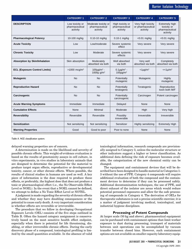
BackgroundLike many of the major pharmaceutical compa-nies, BI developed a classification system fordescribing the level of potency of materials.Table A summarizes a five-category classifica-tion system for NCEs and the criteria used inassigning a classification to a compound. Allrelevant data about the compound are reviewed.This includes chemical, physical, pharmaco-logical, and toxicological data from both humanand animal subjects. A hazard assessment isconducted and a determination is made as towhich Hazard Category is the “best fit.” Teammembers collectively apply their expertise inindustrial hygiene, toxicology, pharmacology,occupational medicine, and clinical medicine toreview the data for the pharmaceutical activeingredient and make the hazard category as-signment. Both acute and chronic data are con-sidered, and the assignment relies on profes-sional judgment. To assess potential acute ef-fects, both the toxicity and pharmacologicalactivity of the compound are evaluated. Thetype of pharmacological effect(s) expected, themechanism of action, and the dose required toproduce these pharmacological effects are im-portant considerations, as is the severity ofacute (life threatening) effects. This latter as-sessment is a determination of whether medicalintervention might be required and how rapidthe response must be if an overexposure occurs.This information in conjunction with the re-sults of acute toxicity studies in animals pro-vides the likelihood that the compound mayproduce immediate adverse effects. Compoundswith a high order of acute toxicity and poor or
Reprinted from The Official Journal of ISPE
PHARMACEUTICAL ENGINEERING® July/August, 2001 Vol. 21 No. 4
©Copyright ISPE 2001
JULY/AUGUST 2001 • PHARMACEUTICAL ENGINEERING 21
Barrier Isolation Technology
delayed warning properties are of concern.A determination is made on the likelihood and severity of
possible chronic effects. This weight-of-evidence evaluation isbased on the results of genotoxicity assays in cell culture, invitro experiments, in vivo studies in laboratory animals thatare designed to determine the potential for the material toproduce target organ effects, reproductive or developmentaltoxicity, cancer, or other chronic effects. Where possible, theresults of clinical studies in humans are used as well. A keypiece of information is the dose required to produce theseeffects, or preferably, the highest dose that does not produce atoxic or pharmacological effect (i.e., the No Observable EffectLevel or NOEL). In the event that a NOEL cannot be defined,we attempt to define a No Toxic Effect Level or NOTEL.
A judgment is made regarding the severity of chronic effectsand whether they may have disabling consequences or thepotential to cause early death. A very important considerationis whether effects are reversible or irreversible.
The procedure that we follow in developing OccupationalExposure Levels (OEL) consists of the five steps outlined inTable B. Often the hazard category assignment is conserva-tively based on the most sensitive health effect endpoint,especially when there is potential for life threatening, dis-abling, or other irreversible chronic effects. During the earlydiscovery phase of a compound, toxicological profiling is lim-ited by the small quantities available. In the absence of valid
toxicological information, research compounds are provision-ally assigned to Category 3, unless the molecular structure orother indicators suggest a higher or lower classification. Asadditional data defining the risk of exposure becomes avail-able, the categorization of the new chemical entity can bechanged.
The equipment and containment devices that will be de-scribed have been designed to handle material in Categories 1-3 without the use of PPE. Category 4 compounds will requireadditional evaluation of both the compound and the contain-ment devices to determine if they can be processed safely.Additional decontamination techniques, the use of PPE, anddirect exhaust of the isolator are areas which would reducepotential personnel exposures and allow for the safe process-ing of compounds in Category 4. The derivation of OELs fortherapeutic substances is not a precise scientific exercise; it isa matter of judgment involving medical, toxicological, andindustrial hygiene disciplines.
Processing of Potent CompoundsAt larger scale (50 kg and above), pharmaceutical equipmentcan be purchased with containment options that limit workerexposure to dust during processing; transport of materialsbetween unit operations can be accomplished by vacuumtransfer between closed bins. However, such containmentoptions are not available on smaller capacity laboratory equip-
Table A. NCE classification system.
CATEGORY 1 CATEGORY 2 CATEGORY 3 CATEGORY 4 CATEGORY 5
DESCRIPTION Low toxicity or Moderate toxicity or High toxicity or Very high toxicity Extremely highpharmaceutical pharmaceutical pharmaceutical or pharmaceutical toxicity or
activity activity activity activity pharmaceuticalactivity
Pharmacological Potency 10-100 mg/kg 0.10-10 mg/kg 0.10-1 mg/kg <0.01 mg/kg <0.01 mg/kg
Acute Toxicity Low Low/moderate Severe systemic Very severe Very severeeffect
Chronic Toxicity Low Moderate Severe systemic Very severe Very severeeffects
Absorption by Skin/Inhalation Skin absorption Moderately Well absorbed Very well Completelyabsorbed via both via both absorbed via both absorbed via both
ECL (Exposure Control Limits) >1000 mcg/m3 100µg/m3 - 0.1µg/m3 - <1µg/m3 <<1µ/m3
1000µ g/m3 100µg/m3
Mutagenic No No Potentially Mutagenic Highlymutagenic mutagenic
Reproductive Hazard No No Potentially Teratogenic Reproductiveteratogenic toxin both M/F
Carcinogenic No No Potentially Carcinogen Potent carcinogencarcinogenic
Acute Warning Symptoms Immediate Immediate Delayed None None
Cumulative Effects None Minimal Moderate High Very high
Reversibility Reversible Reversible Possibly Irreversible Irreversibleirreversible
Sensitization Not sensitizing Not sensitizing Sensitizer Highly sensitizing Extremely High
Warning Properties Good Good to poor Poor to none None None
©Copyright ISPE 2001

22 PHARMACEUTICAL ENGINEERING • JULY/AUGUST 2001
Barrier Isolation Technology
2. flexibility for using lab for both potent and non-potentcompounds
3. ability to work on a scale of 200 grams to 2 kg
4. ability to adopt new process equipment into the lab withoutredesigning containment practices
5. allow development on compounds with an OEL on the orderof 0.1 micrograms/cubic meter of air
Strategy DevelopmentA discussion of how our containment strategy evolved isinformative since it identifies the approaches that were evalu-ated and abandoned due to their impracticality.
Our first generation concept was to construct a down draftbooth that would be used in conjunction with PPE. It was feltthat this would be a quick solution for handling potent com-pounds; however, based on achievable particle capture, thisapproach would not be useful for compounds with OELs of50µg/cubic meter or below without using PPE. When theoperation was complete, the entire laboratory potentially wouldhave to be cleaned, and we would need to engineer a means ofentry and exit into the lab for workers to safely remove theirPPE.
The second generation approach was adopted to decreaseour reliance on PPE and to minimize the need to clean a largelaboratory space upon completion of an operation. We envi-sioned that all work would take place in a HEPA filtered labfitted with airlocks and mist showers to contain the materialwithin a smaller lab space. This would allow personnel to exitand then remove their PPE safely. All material transfers anddust generating operations would be performed in a glove boxwithin the HEPA filtered laboratory. One large glove box
Figure 1. Typical wet granulation process using containment isolators.
ment used when making the first solid dosage form for a NCEat the 200g - 1 kg scale. At this small scale, past practice hasbeen to work in a chemical fume hood, or in an open lab wearingsome form of respirator to prevent inhalation of dust. However,the goal was to be able to work with small-scale equipment inthe lab in either a contained or non-contained manner withoutthe PPE and the facility clean up issues. This will allow thedevelopment of all levels of compounds in house.
When performing analytical testing, potent compoundsneed to be treated as hazardous and work with them in aproperly contained environment. This means that for process-ing operations that generate considerable amounts of dust (i.e.dispensing active, mixing, granulating, milling, tableting),containment strategies need to be developed in order to doprototype formulation development work. We found that weneeded to develop criteria to guide our decisions. These criteriaevolved as we learned the advantages and disadvantages tovarious isolation/containment approaches. The initial criteriawere:
1. safety of personnel working with the potent material andthose scientists in adjacent labs not involved with thesematerials
Table B. Procedure for development of Occupational Exposure Levels (OEL).
Step 1 Determine the impact of the pharmacological effect onnormal healthy individuals. Identify the lowest appropriateestimated or known NOEL/NOTEL for a pharmacologicaleffect in animals or humans.
Step 2 Compile available information concerning the occupa-tional toxicity of the substance by any relevant route ofexposure. The following are considered in this review:• Human and animal pharmacology and doses• Skin toxicity, eye irritation and sensitization• Metabolism• Genetic Toxicity• Carcinogenicity• Mutagenicity• Reproductive and developmental effects• Reports of occupational exposures
Step 3 Collect information pertaining to the exposure route andhuman/medical experience:• Routes of exposure and exposure conditions• Industrial Hygiene analytical method developed• Exposure data• Medical surveillance
Step 4 Assign and document appropriate safety factors (oruncertainty factors) taking into account:• Interspecies extrapolation• Serious or irreversible effects• Relevance of the observed action/mechanism for
human group at special risk• Mode of action• Half-life, accumulation, etc.
Step 5 Use the following formula to calculate the occupationalexposure level (expressed in milligrams per cubic meterof air) based on an 8 hour work shift:
(NOEL or NOTEL) × (50 kg average female worker)OEL = _____________________________________________
(serum half life) × (% absorption) ×(respiration over 8 hour work day ) × (safety factor)
This formula or a similar one is widely used within theindustry to calculate the occupational exposure level.
©Copyright ISPE 2001

JULY/AUGUST 2001 • PHARMACEUTICAL ENGINEERING 23
Barrier Isolation Technology
would accommodate the operations of weighing active drug,granulating, milling, blending, and tableting. An initial clean-ing of residual powder would be performed inside the glove boxand then the equipment would be removed for final cleaningand breakdown during which lab personnel would be wearingPPE. As we worked through the logistics of this approach,several problems were identified. First, the concept that oneglove box could support all of the equipment in a standard wetgranulation process was impractical. The ergonomics associ-ated with operating and cleaning a tablet press, a high sheargranulator, a mill, a fluid bed granulator/dryer/coater, etc.,were unique enough that one glove box could not accommodateall of these operations. Several stopping points would have tobe designed into the usual work flow of the granulation processto clean equipment, move it out of the lab, and pull newequipment in. Depending on the OEL of the drug being pro-cessed, this movement of equipment in and out would necessi-tate a cleaning of the entire laboratory prior to equipmentchange over. These potential stopping points in the process toclean the lab and move equipment in and out contradicted ourpreferred work practice of cleaning after completing the entiremanufacturing process.
Our third and final concept was to contain the potentcompound at source in the equipment. We developed an isola-tor system, which included a HEPA filtered air design compo-nent such that all of the engineering containment controlswould be designed into the isolator and not into the laboratoryas in our earlier approaches. All material transfers would takeplace in a closed environment, either inside the barrier isola-tors or within a HEPA filtered weighing hood. This allowed the
Figure 2. Tablet press isolator.
equipment to be operated in normal laboratory space and didnot require air locks and exit showers.
Description of Equipment and IsolatorsFigure 1 depicts a typical wet granulation process for produc-ing pharmaceutical tablets. The process is a series of weighing,mixing, granulating, drying, and compression operations all ofwhich are contained in isolators or performed inside a HEPAfiltered weighing hood. No material transfers take place out-side of a HEPA filtered environment. There are a total of threeisolators and a weighing hood. The weighing hood is connectedto a HEPA filter and is used to weigh out the active ingredient,and to dissolve this material in water before being added to thebinder solution. The general isolator is designed to containmultiple pieces of equipment one at a time. It is used foroperating an oscillating mill, a high shear co-mill, and a highshear granulator. In addition, it can be used for charging anddischarging mixing totes, that once loaded, can be cleaned,removed, and mixed in the open lab using a drive unit that isnot contained. The fluid bed isolator is used to operate a benchtop, fluid bed unit that can be used for granulation, drying, andWurster coating. The third isolator is dedicated to operation ofa bench top 10 station instrumented rotary tablet press. All ofthe isolators are complete with HEPA filters that re-circulateair back into the isolator with a small amount of the filtered airbeing vented into the room to keep the unit under negativepressure. For the purpose of this article, we will focus ondescribing the process by which tablets are made inside thecontainment isolator dedicated to the tablet press. Ergonomi-cally, this is the most challenging operation to achieve insidean isolator and illustrates all of the handling practices usedthroughout a wet granulation process using all of the isolators.
Operation of Tablet Press Inside IsolatorThe first step is to tool up the press as needed, connect theelectrical cables, misting wand, interior vacuum hose, andtransfer all materials required for compression into the isola-tor at this time. The tablet press isolator is shown in Figure 2.If an isolator panel has been removed, it is more convenient totool up and make all connections prior to reinstallation of thepanel. Once this isolator panel has been reinstalled, the UltraLow Penetration Air Filters (ULPA) equipped vacuum isconnected to the isolator manifold - Figure 3. Sealed polyeth-
Figure 3. Tablet press isolator hook ups.
©Copyright ISPE 2001

24 PHARMACEUTICAL ENGINEERING • JULY/AUGUST 2001
Barrier Isolation Technology
ylene sleeves are installed on the bag out ports. Once theseinstallations are complete, the isolator is turned on and thechamber air pressure is checked via a magnehelic gaugelocated on the front panel - Figure 4. This ensures the unit issealed and not leaking. To start the tableting operation, thepowder hopper is filled with granulation and the manifold isadjusted to turn on the vacuum for local dust collection withinthe tablet press. The tablet press force monitoring system isturned on and the press is started using the externally mountedpress control panel - Figure 5. The vacuum is adjusted for theproper amount of turret dust extraction using a butterfly valveconnected to the isolator manifold. The isolator chamber airpressure is adjusted to compensate for the turret vacuum byadjusting a slide gate valve located on top of the isolator -Figure 6. Initial tablet samples are collected by passing tabletsout the tablet chute directly into a polyethylene bag for evalu-ation of tablet weight, thickness, and hardness. The press isthen adjusted as needed and granulation can be added to thehopper as required by filling from inside the isolator or baggingmaterial in from the outside via the sealed polyethylene sleevelocated just above the hopper. When compression is complete,the product can be removed through a bag out port or throughthe pass through chamber - Figure 7. The tablet press andisolator are now ready for cleaning.
Cleaning StrategyThe term cleaning means to reduce the concentration of theactive ingredient on surfaces of the machine and the enclosureto an established acceptable level. Cleaning is divided intodeactivation and cleaning. Deactivation is the operation thatis performed to reduce or immobilize the potent compound tothe point that the material cannot produce an airborne concen-tration exceeding the exposure guideline for the compound.This is accomplished by a number of steps and should bevalidated for individual compounds because each has differentcharacteristics in terms of particle size, solubility, density,surface characteristics, etc. The validation of cleaning is re-quired for the protection of employees when working withpotent compounds.
Description of Cleaning ProcessAfter processing is complete, an initial vacuuming (ULPAfiltered Vacuum) is performed to remove gross powder. Parts
routinely cleaned in a sink can be “bagged-out” for cleaning.These bags are opened in the sink under water to minimizedust exposure. Larger pieces of the equipment are cleanedinside the isolator by wiping first with a cleaning solution inwhich the compound is soluble, followed by rinsing with water.Based on the sampling results described later, a misting wandwas attached to the manifold for a direct supply of water. Forhard to reach places a series of special tools such as squeegeesare useful. Testing of the deactivated equipment inside theisolator is routinely performed as part of the validation processthat will be described later. In the case of non-GMP operations,if the deactivation step is being used as a cleaning step, a finalrinse may be used. All deactivation materials are bagged outof the isolator and disposed of in a safe manner. Once the unithas dried, a visual inspection is conducted to determine if anyvisible powder can be detected. If the compound is highlypotent at levels of less than one microgram, it is good practiceto collect a swab from several locations within the enclosureand have it analyzed to determine that the potent compound isnot present above the exposure limit before opening the isola-tor.
Once the isolator has been cleaned, it can be opened and theequipment can be further cleaned if GMP cleaning clearance isneeded to release the equipment prior to the production of a
Figure 4. Press isolator magnehelic gauge.
Figure 5. Tablet press controls.
©Copyright ISPE 2001

JULY/AUGUST 2001 • PHARMACEUTICAL ENGINEERING 25
Barrier Isolation Technology
future GMP batch. Such cleaning can be performed in accor-dance with the standard operating procedures for a particularpiece of equipment.
ValidationOur approach has been to use lactose as a surrogate for thedrug in the first round of validation experiments. Lactose wasselected due to its dustiness and the availability of sensitiveanalytical methods. The low detection limit allowed samplecollection intervals to coincide with the normal work activities:set up, compression, tablet testing, and cleaning. Prior tosafety batch operations, background samples were collected inthe lab during routine activities. During safety batch opera-tions, personal sampling pumps equipped with 25mm glassfiber filters were placed on both operators, downstream of theHEPA filter exhaust from the isolator and next to the ULPAfiltered vacuum. The filters were changed out at various stagesof the process to quantify exposures specific to each part of theprocess. Upon completion of testing, the filters were sent to anindependent testing laboratory for HPLC analysis. The per-sonal sampling results were used to generate eight hour TimeWeighted Average (TWA) exposures. These TWA exposureswere then compared to the OEL established for the compoundof interest. In addition, a P Trak TM Ultra fine Particle Counterwas used to identify possible points of contaminant release.Upon completion of the cleaning operation, a sample wascollected inside the isolator.
The initial personal and area samples results are shown inTable C. Measured concentrations ranged from 0.12 µg/m3 to4.4 µg/m3. Using the particle counter, leakage from the ULPAfiltered vacuum at a level of 19,000 particles/cm3 was mea-sured at one location at the filtered exhaust. The leak was alikely contributor to the higher than expected personal expo-sures. As a result, the ULPA filter was changed and testedagain prior to use in the next batch. The sample collected insidethe isolator after cleaning had measurable levels of lactose(0.44 µg/m3). To reduce residual airborne dust, the cleaningprocedure was revised to include covering the press with apolyethylene bag after the press was cleaned and misting theinterior of the isolator using a misting wand.
The next simulation batch was sampled as described previ-ously. Results from air monitoring are shown in Table D.Personal sampling results ranged from 0.21 µg/m3 to 0.91 µg/
m3 for Operator 1 and were below the limit of detection forOperator 2. The highest concentration measured for Operator1 occurred during cleanup. While collecting this sample, theseal on an out port bag ruptured possibly resulting in asignificant release of lactose. Equipment was heat and tiesealed when being bagged out of the isolator to prevent bagruptures in all future batches. Area samples were below theOEL with the exception of one sample collected near thevacuum (2.3 µg/m3).
Due to the continuing high concentration of lactose mea-sured near the vacuum, we replaced the ULPA filtered vacuumand isolated the vacuum from the lab. Exposures were higherfor Operator 1 who removed the tablets from the isolator andperformed tablet testing in the vented weighing hood than forOperator 2 who worked at the isolator only - Table D. Due tothese differences, tablets were removed from the isolator inbags or covered weigh boats. In addition, PPE was upgraded todouble gloves and sleeves for tablet testing, and the operatorperforming testing removed and bagged the outer layer of PPEinside the hood before taking his hands out of the hood. Resultsfrom the third validation batch are shown in Table E. Theseresults were all below the detectable limit of the lactose assay.The experiment was replicated to demonstrate repeatabilityand similar results were obtained and are shown in Table F.
Discussion/ConclusionsThe primary objective of this work was to develop an approachthat would provide adequate worker safety during small scaleprocessing of potent compounds classified as Category 3. Theapproach was to include a strategy for protecting both theoperators working directly with the potent materials and otherlaboratory personnel throughout the facility. The approachdescribed above provides processing capability under the highlevel of worker protection appropriate for Category 3 whileallowing processing in general laboratory space. This featureminimizes the need for costly facility modifications such asairlocks, showers, and changing rooms, which would be re-quired to contain material to a given laboratory and effectivelyprotect the surrounding facility in the absence of a barrierisolator. While this approach minimizes the need for workerPPE for processing most Category 3 compounds, one can stillwork with the more toxic Category 4 materials by adding the
Figure 7. Tablet press isolator bag out port and pass through.Figure 6. Tablet press isolator slide gates for controlling isolator air pressure differential.
©Copyright ISPE 2001

26 PHARMACEUTICAL ENGINEERING • JULY/AUGUST 2001
Barrier Isolation Technology
Table E. Lactose validation batch 3.
Concentration TWALocation µg/m3 µg/m3
Operator 1 tabletting and sampling <0.15 <0.04
Operator 1 tabletting and bagging <0.16 <0.04
Operator 1 tablet testing <0.15 <0.04
Operator 1 clean up <0.071 <0.02
Operator 2 charging and <0.15 <0.04operating press
Operator 2 tabletting and sampling <0.15 <0.04
Operator 2 during testing <0.17 <0.04(away from hood)
Operator 2 clean up <0.071 <0.01
Area sample by vacuum <0.13 N/A
Area by vacuum during clean up <0.11 N/A
appropriate PPE and administrative controls as additionalprotection. Lastly, the use of isolator technology is consistentwith the OSHA directive to minimize reliance on PPE controlsand to maximize the role of engineering controls as the mainbasis of worker protection when handling potent compounds.
Barrier isolation is not an instantaneous fix for handlingpotent compounds. The proper design of the isolator for aparticular piece of equipment or process is a nontrivial task. Itrequires an intimate knowledge of the manufacturing processand equipment operation. The development of each isolatorhas been a multi step process. A detailed mock-up of theisolator to determine the optimal configuration of gloves,sample ports, and equipment utilities is needed. This mock upalso allows the user to address ergonomic issues of the process.Evaluation of each stage of the design by skilled operators withdetailed knowledge about the process is crucial to developingan effective isolator that is easy to use. Identification of theoptimal location of controls to minimize exposure of electronicand pneumatic controls required considerable considerationand evaluation of the functional operation of the equipment toobviate cleaning and contamination issues. This ensured thatthe equipment was safe for operation outside of the isolatorusing Category 1 and 2 compounds. Next, after the design wasstructurally sound, a prototype isolator was constructed. Per-formance testing and validation were then performed withlactose to determine the best operating practices to minimizecontamination and maximize ease of use prior to working withpotent material. As more experience was gained working withthe isolator, minor modifications were made to the prototype toarrive at the final working configuration.
The use of an easily detectable surrogate compound (lac-tose) during the initial stages of the isolator validation proved
very useful. We were able to test the integrity of the isolatorsas well as the adequacy of procedures for operating the equip-ment and handling of potent materials without operator expo-sure. After achieving acceptable air monitoring and cleaninglevel results using lactose, active batches may be tested usingthe procedures developed with the lactose batches.
During initial batch development, workers should be inPPE and the room closed for use until containment of thecompounds of interest could be demonstrated using analyticalresults from swabbing the equipment, including areas outsideof the isolator for the potent compound. This type of validationprocedure should be completed for each new compound usedinside the isolator.
It is important to note that the design of any containmentsystem for working with potent compounds should not be“cookie-cutter” approach. The system must be designed withthe needs of the operators, the existing facility, and the process
Table C. Lactose validation batch 1.
Concentration TWALocation µg/m3 µg/m3
Area Sample Background <0.12 N/A
Area Sample Background <0.098 N/A
Operator 1 tabletting and testing 1.4 0.33
Operator 1 tabletting and testing <0.15 0.33
Operator 1 tabletting and testing <0.13 0.33
Operator 1 cleanup 0.82 0.33
Area inside enclosure post clean up 0.44 N/A
Table D. Lactose validation batch 2.
Concentration TWALocation µg/m3 µg/m3
Operator 1 tabletting and testing 0.27 0.24
Operator 1 tabletting and testing 0.21 0.24
Operator 1 cleanup 0.91 0.24
Operator 2 tabletting and testing <0.11 <0.04
Operator 2 tabletting and testing <0.12 <0.04
Operator 2 cleanup <0.059 <0.04
Area sample by vacuum 2.3 N/A
Area inside enclosure post cleanup <0.14 N/A
Table F. Lactose validation batch 4.
Concentration TWALocation µg/m3 µg/m3
Operator 1 tabletting and sampling <0.097 <0.07(bags)
Operator 1 tabletting and sampling <0.095 <0.07(weigh boat)
Operator 1 tablet testing <0.12 <0.07
Operator 1 tablet testing <0.092 <0.07
Operator 1 clean up <0.082 <0.07
Operator 2 tabletting and sampling <0.1 <0.06(bags)
Operator 2 tabletting and sampling <0.1 <0.06(weigh boat)
Operator 2 assisting tablet testing <0.13 <0.06
Operator 2 assisting tablet testing <0.1 <0.06
Operator 2 clean up <0.089 <0.06
Area by vacuum <0.047 N/A
Area by vacuum during clean up <0.084 N/A
©Copyright ISPE 2001
JULY/AUGUST 2001 • PHARMACEUTICAL ENGINEERING 27
Barrier Isolation Technology
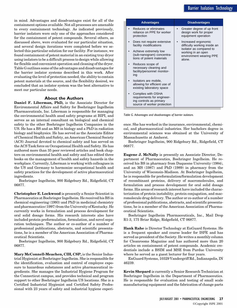
in mind. Advantages and disadvantages exist for all of thecontainment options available. Not all processes are amenableto every containment technology. As indicated previously,barrier isolators were only one of the approaches consideredfor the containment of potent compounds. Several others, asdiscussed above, were evaluated for our particular situation,and several design iterations were completed before we se-lected this particular solution for our facility. For instance, wefound containment of potent material in an existing tray dryerusing isolators to be a difficult process to design while allowingfor flexible and convenient operation and cleaning of the dryer.Table G outlines some of the advantages and disadvantages forthe barrier isolator systems described in this work. Afterevaluating the level of protection needed, the ability to containpotent materials at the source, and the flexibility desired, weconcluded that an isolator system was the best alternative tomeet our particular needs.
About the AuthorsDaniel F. Liberman, PhD, is the Associate Director forEnvironmental Affairs and Safety for Boehringer IngelheimPharmaceuticals, Inc. Liberman is responsible for managingthe environmental health ansd safety programs at BIPI, andserves as an internal consultant on biological and chemicalsafety to the other Boehringer Ingelheim Companies in theUS. He has a BS and an MS in biology and a PhD in radiationbiology and biophysics. He has served as the Associate Editorof Chemical Health and Safety, an American Chemical Society(ACS) Journal devoted to chemical safety and has served onthe ACS Task force on Occupational Health and Safety. He hasauthored more than 35 peer reviewed articles and book chap-ters on environmental health and safety and has edited threebooks on the management of health and safety hazards in theworkplace. Currently, Liberman is working with colleagues inthe US and Germany to harmonize occupational health andsafety practices for the development of active pharmaceuticalingredients.
Boehringer Ingelheim, 900 Ridgebury Rd., Ridgefield, CT06877.
Christopher E. Lockwood is presently a Senior Scientist inPharmaceutics at Boehringer Ingelheim. He received his BS inchemical engineering (1993) and PhD in medicinal chemistryand pharmaceutics (1997) from the University of Kentucky. Hecurrently works in formulation and process development fororal solid dosage forms. His research interests also haveincluded protein preformulation, formulation, and novel sepa-ration techniques. The author or co-author of a number ofprofessional publications, abstracts, and scientific presenta-tions, he is a member of the American Association of Pharma-ceutical Scientists.
Boehringer Ingelheim, 900 Ridgebury Rd., Ridgefield, CT06877.
Mary McConnell-Meachen, CIH, CSP, is the Senior Indus-trial Hygienist at Boehringer Ingelheim. She is responsible forthe identification, evaluation and control of employee expo-sure to hazardous substances and active pharmaceutical in-gredients. She manages the Industrial Hygiene Program forthe Connecticut campus, and provides technical and programsupport to other Boehringer Ingelheim US locations. She is aCertified Industrial Hygienist and Certified Safety Profes-sional with 23 years of safety and industrial hygiene experi-
ence. She has worked in the insurance, environmental, chemi-cal, and pharmaceutical industries. Her bachelors degree inenvironmental sciences was obtained at the University ofMassachusetts at Amherst.
Boehringer Ingelheim, 900 Ridgebury Rd., Ridgefield, CT06877.
Eugene J. McNally is presently an Associate Director, De-partment of Pharmaceutics, Boehringer Ingelheim. He re-ceived his BS in pharmacy from Duquesne University (1984),and an MS (1987) and PhD (1989) in pharmacy from theUniversity of Wisconsin-Madison. At Boehringer Ingelheim,he is responsible for preformulation/formulation developmentof recombinant proteins, delivery of macromolecules, andformulation and process development for oral solid dosageforms. His areas of research interest have included the charac-terization of protein instability, protein conjugation, and mac-romolecule drug delivery. The author or co-author of a numberof professional publications, abstracts, and scientific presenta-tions, he is a member of the American Association of Pharma-ceutical Scientists.
Boehringer Ingelheim Pharmaceuticals, Inc., Mail DropR1-3, 175 Briar Ridge, Ridgefield, CT 06877.
Hank Rahe is Director Technology at EnGuard Systems. Heis a frequent speaker and course leader for ISPE and hasserved as president of the Society. He writes a monthly columnfor Cleanrooms Magazine and has authored more than 20articles on containment of potent compounds. Academic cre-dentials include a BSIM and MSE from Purdue Universitywhere he served as a guest lecturer for four years.
EnGuard Systems, 10329 Vandergriff Rd., Indianapolis, IN46239.
Kevin Shepard is currently a Senior Research Technician atBoehringer Ingelheim in the Department of Pharmaceutics.He is responsible for evaluation and testing of small scalemanufacturing equipment and the fabrication of change parts
Table G. Advantages and disadvantages of barrier isolators.
Advantages
• Reduces or eliminatesreliance on PPE for workerprotection
• Does not require extensivefacility modifications
• Achieve extremely low(sub-nanogram) concentra-tions of potent materials
• Reduces scope ofnecessary cleaning andfacility/personnel monitor-ing
• Isolators are mobile,allowing for efficient use ofexisting laboratory space
• Complies with OSHArequirements for engineer-ing controls as primarysource of worker protection
Disadvantages
• Greater degree of up frontdesign work for properequipment operation
• Increased ergonomicdifficulty working inside anisolator as compared toworking in an openenvironment wearing PPEalone.
©Copyright ISPE 2001

28 PHARMACEUTICAL ENGINEERING • JULY/AUGUST 2001
Barrier Isolation Technology
to adapt commercial equipment to development activities. Hisresponsibilities also include manufacturing and evaluation ofdevelopment batches and other formulation development ex-periments.
Boehringer Ingelheim, 900 Ridgebury Rd., Ridgefield, CT06877.
Glenn Snow is presently a Senior Research Associate, De-partment of Pharmaceutics, Boehringer Ingelheim. He re-ceived his BA in chemistry from Western Connecticut StateUniversity (1994). At Boehringer Ingelheim, he is responsiblefor preformulation/formulation development for oral solid dos-age forms. He is a member of the American Chemical Society.
Boehringer Ingelheim, 900 Ridgebury Rd., Ridgefield, CT06877.
...the use of isolator technology is consistent with the OSHA directive tominimize reliance on PPE controls and to maximize the role of engineering
controls as the main basis of worker protection...““ ““
©Copyright ISPE 2001

32 PHARMACEUTICAL ENGINEERING • JULY/AUGUST 2001
Engineering Changes
The Changing Face ofEngineering for Major CapitalProjects
The Changing Face ofEngineering for Major CapitalProjects
Oby Joseph R. Hettenbach, PE
This articleexplores howbetterrelationshipsbetweencustomers andengineeringdesign companiesresult inimproved quality,betterperformance,and a costeffective process.
Over the last several years, there havebeen some significant changes in engi-neering for major capital projects. The
paradigm has been shifting as a result of chang-ing attitudes and organizational structures, theneeds of customers, and the major engineeringdesign firms who service them. The partneringconcept is now very much in vogue althoughsomewhat limited in its application. The intentof this article is to explore where we have comefrom, what we are getting into, and where weseem to be heading in our relationships withengineering design firms.
A good working knowledge of the designprocess traditionally utilized for major capitalprojects was developed, working closely on sev-eral projects with design personnel from anengineering design company. Six projects wereexecuted over a 12-year period, including fiveyears as a resident in their facilities, and exten-sive work in the field. The scope of this involve-ment included management of the process de-sign function for a number of projects rangingfrom $25 to $300 million, including new plantsand upgrades for bulk pharmaceutical manu-facturing; and a state-of-the-art research devel-
opment complex encompassing apilot plant, kilo lab, prep labs andlaboratories. Insights into workingrelationships between customersand engineering design companiesand changes we have experienced inour collaborations are presented.
In the 1980s, the workingmode between clients and engineer-ing companies could be character-ized as strained. We didn’t alwaysdo the best job defining the scope ofour projects. The net result was thatscope changes translated into higherdesign costs, schedule delays, andincreased revenues for the engineer-ing companies. Our experienceshows us that this has been true forprocess control engineering firms aswell - where the “dynamic scope”model (or the perceived moving tar-get) generates higher design costs.The interaction between the two “op-posing parties” was iterative in na-ture, and it was very difficult tomanage the program from theclient’s side. As an example, whileworking at a big engineeringcompany’s “house” at the beginningof the first major project we did withthis firm in 1987, a situation devel-oped in which the number of designchange orders was escalating and
Figure 1. Top of a reactionvessel - digital photograph of aplastic model.
Reprinted from The Official Journal of ISPE
PHARMACEUTICAL ENGINEERING® July/August, 2001 Vol. 21 No. 4
©Copyright ISPE 2001

JULY/AUGUST 2001 • PHARMACEUTICAL ENGINEERING 33
Engineering Changes
threatening the stability of the project. We engaged in somevery heavy negotiating to come up with a mutually agreeableway to corral the design activities and better keep the cost inline with expectations. Of course, the development of a “holdback list” helped save the day. This list identified a number ofproject elements, which could be deferred without signifi-cantly affecting the mission of the project. We completeddetailed engineering for these elements, but held up imple-mentation until we were satisfied that sufficient funds wouldbe available to include them in the construction phase. Wehave successfully incorporated this tactic into our strategy forseveral projects following that first one.
Having resolved those issues during the front end of thatfirst major project, things seemed to be going smoothly as wewere digging into the details. However, we were quite sur-prised to get some strong direction from our project manager toget more involved with the designers on a day-to-day basis.
We took steps to implement the directive, and it was at thatpoint that we started to become more interactive with thedesigners. At first, there was quite a bit of resistance from theirside, but in time they began to see the wisdom of it. We had asmall staff in residence varying from 6 to 12 people from ourcorporate office and one of our operating facilities, and under-took a number of initiatives.
• We worked with the designers much more closely to makesure they satisfied our needs.
• We increased the level of our involvement during thedetailed design.
• We developed relationships with the key design personnel,typically layout/piping design people.
• We concentrated on communications and the developmentof “win-win” approaches, and built trust in a team buildingmanner.
This partnering/team approach has worked quite well on laterprojects, but there are some pitfalls. The project organizationneeds leadership and direction to keep the partners in tunewith the program, and to most efficiently use the resources athand.
In the early 1990s, we once again engaged the same engi-neering design company to do a much larger project. This timearound, we were more experienced, better prepared, and man-aged our side of the program differently.
• We “demanded” to have certain key individuals in therespective design disciplines as part of their team. Thishelped build our confidence since it would effectively short-circuit the project learning curve.
• We developed and handed over more refined General Ar-rangement drawings (GAs) and Process and Instrumenta-tion Diagrams (P&IDs) to the engineering design companythan we had in the past. GAs show the details of equipmentand floor layouts. P&IDs show the process equipment,piping, instrumentation, and the interconnectivity withother piping and equipment.
• We started out by taking the position that this project wasvery similar to the previous one that we had done together,
and therefore, we were primed to save lots of money on thedesign. However, we performed analyses with the coopera-tion of the engineering company’s key piping/layout leadperson to assure ourselves that we were on the right track.As a result of these analyses, we came to an agreement andunderstanding regarding those specific elements appropri-ately selected from the earlier project that we could safelyuse for the current project. We effectively avoided the trapof maintaining the stance that “this job was the same as theother job,” which we all know is never quite the case.
• We had a much larger staff in residence this time around(up to 18 engineers) and mostly avoided the anguish ofmanaging significant change orders by having a system inplace to deal with the changes.
The cost performance on this second project was very good withboth sides benefiting by the virtues of an incentive programdeveloped between the parties. We negotiated a metric ofaverage man hours for design per equipment piece based on anequipment list agreed to by both parties, and our past experi-ences (historical data). Good performance resulting in fewerman-hours per equipment item was rewarded as savingsshared by both parties. This translated into lower costs for us,and higher profits for the engineering design company. At thesame time, our working relationship was improved in theprocess. In many respects we were operating as a partnershipbefore “partnering” became popularized in the project engi-neering business.
We developed a plastic detailed scale model for this project,which incidentally was the last one done by this company. Wewere told that this was one of the best models they had everbuilt, and one of their best projects (see Figure 1).
However, 3-D computer design (see Figure 2) was on thehorizon and the use of a plastic model was becoming history,which was disappointing to those seasoned in the use of theplastic model tool. For the record, use of the plastic scaledmodel had several advantages.
• It was much easier on the eyes and the faculties than itscomputer 3-D counterpart.
• It allowed the project team to view the process facilitydesign development from an overall perspective.
Figure 2. Top of a reaction vessel - computer graphic 3-D picture.
©Copyright ISPE 2001

34 PHARMACEUTICAL ENGINEERING • JULY/AUGUST 2001
Engineering Changes
• It provided a constant ready reference, and was very userfriendly for lengthy reviews by relatively large groups.
• The plastic model was not subject to computer systemupsets/failures, and it was useful to construction personnelfor visualization and logistics.
• It provided a vehicle for training of operating personnel,and ultimately provided a nice showcase for the entrancelobby of the facility.
With regard to costs of the different methods versus benefitsachieved, no cost comparisons or detailed performance com-parisons are included in the scope of this article. The ½ inchscale plastic model is rarely used now by engineering compa-nies, and there are many variables that affect the cost ofapplications using the various 3-D computer design systems.
We followed up with this same company on a number ofother projects, enjoying the fruits of our partnership. We setsome records along the way for metrics such as piping man-hours per pipe line using the evolving 3-D computer designtools, but the climate was changing. We, as clients, weresubject to increasing pressures to reduce costs. Having decidedto no longer employ in-house detailed design engineeringresources, we were unable to muster the numbers of qualifiedengineers we had become accustomed to, and we were less thancomfortable with regard to the makeup of our project teams. Inaddition, the retirement of some key personnel and the lack oftraining of their replacements had taken a toll on the processengineering capabilities of this particular company, and oth-ers we were dealing with. A number of smaller engineeringcompanies entered the arena, some with very good processexpertise and much lower turnover of personnel.
It was becoming increasingly clear that there was a need tochange our approach, and for the engineering companies toconsider changing the way they do business. This was not asmall chore from our side with limited resources. On the otherhand, the prospects of transforming the traditional “machineworks” operations typical of the large engineering houses to bebetter in tune with our needs in the shorter term, did not looktoo promising.
The use of 3-D computer design systems was sold on thepremise (actually the promise) that the design process wouldbe much better and cheaper than the manual systems. Inpractice, based on some of the earlier applications of thissoftware tool, the costs of the 3-D designs were at first higherwhen compared to the use of a plastic model for design execu-tion. However, the 3-D approach offered many benefits in theconstruction phase.
• The 3-D design provided machine drawn isometrics.
• The “clash check” tool helps to avoid (minimize) interfer-ence in the field.
• The 3-D software provides a readily available bill of mate-rials.
• The ability to produce plans/orthographics and elevations/sections on demand is useful to improve visualization andsupport construction activities.
The 3-D computer design systems have been in use for morethan 10 years, and many of the companies with significantexperience using 3-D design can now report overall project costsavings (Total Installed Cost) using this tool when it is appliedproperly. Re-work during construction due to design errors onmany projects has been generally reduced to below 1%, whichtranslates into considerable cost savings. However, there area number of issues which still need to be resolved in theapplication of this tool.
A few years ago we challenged a number of engineeringcompanies to address our concerns with 3-D computer designsystems. We asked these companies to come up with ways toallow us to mimic a semblance of the “control” we enjoyed usingthe plastic model.
In practice:
• Many people have trouble visualizing what they’re shownon the screen.
• Depth perception is not nearly as good, compared to work-ing with the plastic model.
• It also is difficult (tedious) to spend the extended timeperiods required for design reviews, and cumbersome toinvolve larger groups for such reviews.
• Of course, larger screens and “layered” approaches help, butthese features alone can not solve all the problems associ-ated with the use of this high-powered tool.
• Clients don’t always take the time to acquire training in the3-D design system they select for their project execution.
Interestingly enough, from our perspective, none of the engi-neering companies has met the challenge - to make the 3-Dtools more client user friendly. In the spirit of “partnership,”we, the clients, should work with these companies to improveour situation.
It also is fair to say that the engineering companies are justbeginning to take more advantage of the potentials the 3-Dcomputer design tools offer. One example of this is the use ofthe “intelligent P&ID’s” tool which should improve the overalldesign approach by providing a more disciplined structure todevelop the design. The tool also offers means to “program in”detailed information on equipment, instruments etc. whichwill be invaluable during design, construction, commission-ing, qualification, and validation. While this is a good, positivedevelopment, we have a lot of work to do together with theengineering companies to realize the quality improvementsand cost reductions possible with this tool. Beyond 3-D design,other tools that can enhance the design process are the processsimulation models, which some operating and engineeringdesign companies are applying to projects during the concep-tual development phase.
There are a number of common mistakes made on 3-Ddesign jobs.
• The first and most basic is the lack of a well defined scopeby the client along with an appreciation for how muchmoney the client’s management will support for the totalproject cost.
©Copyright ISPE 2001

JULY/AUGUST 2001 • PHARMACEUTICAL ENGINEERING 35
Engineering Changes
• The second is starting the detailed 3-D model before havinga sufficient “body of information” in hand. Optimally, thiswould include:
- fairly well developed P&ID’s
- GAs including equipment and floor layouts
- piping specifications IFD (Issue for Design)
- equipment and instrument specifications and physicaldimensions suitable to model
- preliminary structural design (main support steel andcolumns)
- heating, ventilation and air conditioning (HVAC) includ-ing major duct work design
- electrical design
- piping routing studies for process and utility services
• The third is the lack of a proper level of attention affordedby the client to the 3-D design during its development.
• The fourth is the tendency to go out too soon with construc-tion bid packages (before the 3-D design is essentiallycomplete) due to scheduling pressures.
• An additional aggravating factor is the absence of participa-tion by representatives of the construction managementteam and the construction contractors in the model develop-ment process.
All sub-par 3-D designed project performances can be traced toany or all of these mistakes. Analysis of the record indicates awide range of 14 to 55 piping design man-hours per pipe line asreported for a number of different projects of different sizes. Aclose examination of these projects indicates that the better,more efficient ones were those with stronger front-end efforts.This holds true for all of the 3-D computer design packages thatare commercially available.
While working on the conceptual phase of a major pilotplant project recently, it occurred to us that there was a way toimprove our ability to “manage” a project with less peopleresources, and at the same time reduce the overall designcosts. The key is to “front-load” the project with more detailedwork done during an extended preliminary engineering phaseusing a smaller team to best prepare for the detailed phase(before “letting all the horses out of the barn”!). The elementsof such a program could include:
• Developing a solid scope definition as a team with theengineering design company.
• Ideally, following a solid scope development, a number ofitems should be developed during the preliminary phase toa higher quality level to feed a highly efficient detailedphase.
This would include:
• P&IDs (subject to hazard and operational analysis, andrelatively conceptually change free)
• GAs (layouts) - plans and elevation studies (to set floorheights)
• equipment list and specifications (sufficient to model)
• process controls (systems and instrumentation with poten-tial impact)
• instrument list and specifications (sufficient to model)
• piping specifications (issued for design and ready for inputto the model)
• a structural design with conservative column and mainbeam sizes
• HVAC (including major duct routing and equipment spaceallocation), and electrical designs
• A 3-D study model program, including reactor head nozzleconfigurations and piping routing studies (keying in onmain headers and sub header distributions) for: process(including the special cases of manifold rooms/transferstation “panels”), solvents, drainage, utilities, and ventingsystems. This is done to assure the facility is the right size,constructability has been considered, and costs are wellunderstood.
• Details of process cleaning, materials movement, contain-ment, and solids charging and discharging (packout) strat-egies worked out since these effects significantly impact thelayout.
This should translate to fewer changes and significant overallproject design cost reductions and schedule improvements. Tothe extent possible, the construction management and con-tractors, as well as operations, maintenance, Environmental,Health & Safety (EH&S), quality assurance, and other inter-ested groups from the client’s side should be involved as earlyas possible to get their buy-in and support. This in turn alsowill minimize changes, cost increases, and schedule upsetsdown the road. Delaying commencement of the detailed phaseby not committing too soon to a full blown 3-D program canactually save time, money, and stress overall. Optimally, a 3-D study model would be constructed and a number of studiesperformed at the right time during the preliminary phase(along with the P&IDs, GAs and the development of the otherdocuments listed in the “body of information” above). Thiswould be done to deliver a Basis Of Design (BOD) package tofeed the detailed engineering phase.
While working recently on the front end of that same majorpilot plant project, a piping designer on contract working in ouroffice (with 40 years of experience) was intrigued with this“strong front end” approach. This designer still works by handand at times dabbles with AutoCAD for 2-D work, but the 3-Dcomputer design tool is beyond his reach as he winds down hiscareer. He told us that this was the way they used to do
©Copyright ISPE 2001

36 PHARMACEUTICAL ENGINEERING • JULY/AUGUST 2001
Engineering Changes
projects, and that this approach had been abandoned along theway although he could not understand why that happened.Indeed, this puzzles this writer as well. We surely can learn alot by listening to the designers, who are dedicated to theircraft, and we can improve our performance by sticking withwhat works well. We don’t always find all the answers byapplication of new technologies, and should not lose sight of thebasics.
The potential of the 3-D tool for piping design will beachieved, providing that solid piping designers (not just com-puter technicians) are applying that tool. There is an analog inprocess control design, where properly trained chemical engi-neers improve the quality of the programming effort.
With regard to how the clients can better “manage” the 3-Ddesign effort, there is no substitute for experience, and work-ing with known designers. Short of any revelations in this areafrom the engineering companies, the only practical way ofreasonably staying on top of the design is to have confidence inthe designers who are applying this powerful tool.
In the limit, it would be great if we could use the samedesigners all the time to the extent they are made available.This would avoid (reduce) learning curves and further buildconfidence. This is part of the logic of the “partnership.” On theother hand, we have to keep the engineering companies costdown and our management assured by competitively biddingout detailed designs, which we continue to do.
With regard to our project resource constraints, we havehad issues, at times, with process engineering expertise withsome of the larger engineering companies. We have, on a fewoccasions, evaluated and used some smaller companies to doconceptual front-end studies and some preliminary engineer-ing packages. Further partnering the smaller company withthe larger company for the detailed phase offers potentialimprovements in more focused coverage as well as challengesfrom a project management perspective (more players to bemanaged). Of course, the larger engineering companies shouldwork to strengthen their process engineering and conceptualdesign capabilities. This would improve their position, andbetter suit our needs.
It would be helpful to develop standard approaches withina client company for managing the design of major capitalprojects. There is experience and lessons learned from majorprojects executed throughout a company, which can be learnedfrom, here in the US as well as at locations throughout theworld. Best Practice standards, developed by the clients, shouldbe integrated into the design process. We also should strive tomaintain a good process engineering pool to support theprocess design function and work with the engineering designcompanies. With regard to developing our relationships withengineering design companies, it is essential to maintain aregular dialog between the parties so that we can improve ourperformance while the design business changes. Openness andcooperation are the keys with quality and cost effectiveness themain goals.
It has been observed that the larger engineering companiesare prone to building up and staffing down in response tomarket needs. This pattern is disruptive, a “morale” killer forthe engineering design firm employees, and takes away fromthe positive effects of training programs, which would be morebeneficial if they had a more stable work force. It is postulated
that the implementation of more timely, streamlined, andcooperative approaches, along the lines of what has beenpresented here, will help stabilize the rosters of the biggercompanies. This in turn would benefit the clients. By workingbetter together, we can be more cost effective, have more funat it, and share in our successes!
About the AuthorJoseph R. Hettenbach is a Principal Engineer - Process, forthe Pfizer Global Engineering group in Pfizer, Inc. He has a BSand MS in chemical engineering and an MS in environmentalengineering, all from Manhattan College. He is a licensedProfessional Engineer in New York state. He has served on thesteering committee for the Graduate Chemical Engineeringprogram at Manhattan College, and contributed to the devel-opment of their undergraduate environmental program cur-riculum. He has served as a process design manager on anumber of major Pfizer projects, responsible for interface onthe design floor with the design disciplines of the EngineeringDesign companies involved. This work included detailed scopedevelopment, process, and facility design. He has more than 30years of experience, concentrating on process engineering;process development; project management; environmental,health and safety. He has been instrumental in the introduc-tion of a number of new technologies as first time applicationsin the US pharmaceutical industry, including novel approachesfor solids charging and air pollution control.
Pfizer, Inc., 235 E. 42nd St., New York, NY 10017.
©Copyright ISPE 2001

54 PHARMACEUTICAL ENGINEERING • JULY/AUGUST 2001
Pharmaceutical Glossary: C-E
Pharmaceutical Glossary: C-EPharmaceutical Glossary: C-Eby Michelle M. Gonzalez, Engineering/Quality Manager, Fluor Daniel
These acronymswere compiled tohelp engineersunderstand basicterminology as itapplies to therelatively newbiotechnologyindustry, as wellas the moreestablishedpharmaceuticalindustry.
The completeglossary isavailable onISPE’s Web sitewww.ispe.org.It will includedefinitions ofterms used inbiology,chemistry,HVAC,manufacturingprocesses,medicine,materials,metallurgy,regulatoryconcerns, watertreatment, andwelding.
- C -Calcium - A metallic dyad element of a lustrous
yellow color, symbol Ca, atomic number 20,atomic weight 40.09, melting point 810°,often found in water usually as dissolvedcalcium carbonate, chalk (CaCO3). Soluble inwater, it causes hardness and subsequentscaling.
Calcium Carbonate Equivalent - The valueobtained when salts are calculated in termsof equivalent quantities of calcium carbon-ate. This is a convenient method of reducingall salts to a common basis for comparison.
ppm CaCO3 = ppm ion X
Equivalent weight of CaCO3_______________________________Equivalent weight of ion
Where ion = magnesium, calcium, or otherelements that contribute to hardness.
Calibration - A comparison of a measurementstandard or instrument of unknown accu-racy to detect, correlate, report, or eliminateby adjustment of any variation in the accu-racy of the unknown standard or instrument.
Calibration (ICH API defintion) - The dem-onstration that a particular instrument ordevice produces results within specified lim-its by comparison with those produced by areference or traceable standard over an ap-propriate range of measurements.
Calorie - Any of several approximately equalunits of heat, each measured as the quantityof heat required to raise the temperature ofone (1) gram of water by 1°C from a standardinitial temperature, specially from 3.98°C,14.5°C, or 19.5°C, at a constant pressure ofone (1) atmosphere. Also called “gram calo-rie”, “small calorie”.
The unit of heat equal to 1/100 the quan-tity of heat required to raise the temperatureof one (1) gram of water from 0°C to 100°C atone (10 atmosphere pressure. Also called“mean calorie”.
The unit required to raise the tempera-ture of one (1) Kilogram of water by 1°C atone (1) atmosphere pressure. Also called“kilogram calorie”, “large calorie”.
Calorimetry - Analytical method that mea-sures heat loss or gain resulting from physi-cal or chemical changes in a sample. Differ-ential scanning calorimetry compares theresults of heating a sample to those for heat-ing a reference material. For example, amethod to measure the temperature at which
the sample crystallizes, changes phases, ordecomposes.
Cancer - The name given to a group of diseasesthat are characterized by uncontrolled cellu-lar growth.
Capsid - The external protein shell or coat of avirus particle.
Carbohydrates - A large class of carbon-hy-drogen-oxygen compounds that includes thesugars and their polymers (mainly starch,glycogen and cellulose). Most carbohydratesare produced by photosynthesis in plants.They are the major food compounds for bothplants and animals. One group of carbohy-drates, cellulose, is the primary structuralmaterial of plants.
Carbon Filter - A vessel loaded with activatedcarbon and used to remove organics, chlo-rine, tastes, and odors from liquids, operat-ing on the principle of adsorption.
Carbon Thickness - A measurement of sur-face organic material. Carbon thickness val-ues typically range from 5 to 20 angstroms(Å). Significantly contaminated surfaces canshow surface carbon thickness of 20 ang-stroms (Å) or more.
Carbonate Hardness - That hardness in wa-ter caused by bicarbonates and carbonates ofcalcium and magnesium. If alkalinity ex-ceeds total hardness, all hardness is carbon-ate hardness; if hardness exceeds alkalinity,the carbonate hardness equals the alkalin-ity. (also see: Calcium)
Carcinogen - A substance that causes thedevelopment of cancerous growths in livingtissue. A chemical is considered to be a car-cinogen if it has been evaluated by the Inter-national Agency for Cancer Research (IARC)and found to be a carcinogen or potentialcarcinogen, or if it is listed in the AnnualReport on Carcinogens published by theNational Toxicology Program, or if it is regu-lated by OSHA as a carcinogen.
Carcinogenic - Cancer-causing. Many agentsthat are carcinogenic are mutagens.
Carrier - A person who has a recessive mutatedgene, together with its normal allele. Carri-ers do not usually develop disease but canpass the mutated gene on to their children.
Catabolism - The intracellular phase of me-tabolism involved in the energy-yielding deg-radation of nutrient molecules (for example,glucose to CO2 and H2O). Waste products arecalled catabolites. (also see: Anabolism, andDissimilation))
Reprinted from The Official Journal of ISPE
PHARMACEUTICAL ENGINEERING® July/August, 2001 Vol. 21 No. 4

JULY/AUGUST 2001 • PHARMACEUTICAL ENGINEERING 55
Pharmaceutical Glossary: C-E
Catalase - An enzyme that catalyzes the decomposition ofhydrogen peroxide and molecular oxygen and water.
Catalyst - A compound that increases the rate of a chemicalreaction without being consumed or changed. In the bio-sciences, the term enzyme is used. Enzymes catalyze bio-logical reactions.
Cation - A positively charged particle or ion. (also see: Ion)Cation Exchange - The displacement of one positively charged
particle by another on a cation-exchange material.Cation Exchange Resin - An Ion exchange resin, which
removes positively charged ions (cations) by exchangingthem for hydrogen ions.
Cavitation - A condition of liquid flow where, after partialvaporization of the liquid, the subsequent collapse of vaporbubbles can produce surface damage.
CBER - (also see: center for Biologics Evaluation and Research)Center For Biologics Evaluation and Research (CBER)
- The FDA successor to the Bureau of Biologics concernedwith biologic drugs, and most importantly, with the newprotein and peptide drugs emanating from biotechnology.
Center For Drug Evaluation and Research (CDER) - Thesuccessor to the Bureau of Drugs of the FDA concerned withall SVPs (Small Volume Parenterals), LVPs (Large VolumeParenterals), and non-biological drugs.
Certified Vendor Drawings - Drawings prepared by ven-dors for the fabrication of equipment, specialty componentsand skid mounted systems. These are certified as fabricatedby the vendor and become the official document for theequipment involved.
CDER - (also see: Center for Drug Evaluation and Research)cDNA - (also see: Complementary DNA)Celsius - Of or pertaining to a temperature scale that registers
the freezing point of water as 0°C and the boiling point as100°C under normal atmospheric pressure. Also called“centigrade”. The designation Celsius has been official since1948, but centigrade remains in common use. (also see:Fahrenheit)
Cell - The fundamental unit of life. The living tissue of almostevery organism is composed of these fundamental livingunits. Unicellular organisms, such as yeast or a bacterium,perform all life functions within the one cell. In a higherorganism, a multicellular organism, entire populations ofcells may be designated a particular task. The cells ofmuscle tissue, for example, are specialized for movement.
Cell Bank -Master Cell Bank: The bank of cells, which contain the
original unused mutated cells from which, the Manufac-turing Working Cell Bank is taken. This is usually keptunder lock with very limited access.
Manufacturing Working Cell Bank: The bank of cellsderived from the Master Cell Bank, which are used toseed the fermentation manufacturing process.
Cell Culture - The in vitro propagation of cells removed fromorganisms in a laboratory environment that has strictsterility, temperature, and nutrient requirement; also usedto refer to any particular individual sample. Usually, cellculture takes place in a bioreactor.
Cell Differentiation - The process whereby descendants of acommon parental cell achieve and maintain specializationof structure and function. Muscle cells become muscle cellsand bone cells develop. In humans all the different types ofcells differentiate from the simple sperm and egg.
Cell Fusion - The fusing together of two or more cells tobecome a single cell. This technique has had importantconsequences in immunology, developmental biology, andgenetics. For example, monoclonal antibodies are producedby fusing a spleen cell (producing an antibody specific for
the antigen of interest) with a mouse myeloma cell toproduce a hybridoma which has an indefinitely long lifebecause of the myeloma component and which secretes aspecific antibody. When a human cell is fused with a mousecell, the human chromosomes are progressively lost fromthe resultant hybrid and by correlating the presence ofproteins in the hybrid with the presence of particularhuman chromosomes, genes can be assigned to individualchromosomes.
Cell Lines - When cells from the first culture (taken from theorganism) are used to make subsequent cultures, a cell lineis established. “Immortal” cell lines can replicate indefi-nitely.
Cellulose - A polymer of six-carbon sugars found in all plantmatter, the most abundant biological compound on earth.
Centigrade - (also see: Celsius)Centimorgan (cM) - A unit of measure of recombination
frequency. One centimorgan is equal to a 1% chance that amarker at one genetic locus will be separated from a markerat a second locus due to crossing over in a single generation.In human beings, one centimorgan is equivalent, on aver-age, to one million base pairs.
Centrifugation - Mechanical means of separation based ondifferences in sedimentation rates due to differences indensity between the suspended particles in the liquid.
Centrifuge - A centrifuge operates on the principle of centrifu-gal force, the inertial reaction by which a body tends to moveaway from a center about which it revolves. This techniqueis commonly used to separate solids from liquids or liquidsof different densities. Centrifugal equipment is divided intotwo major types, sedimenters and filters:1. Sedimenters: For sedimentation, batch and continuous
centrifuges are available. There are three types of centri-fuges for continuous sedimentation.a) Disc: constructed on the vertical axis, disc centri-
fuges are solid-bowl units. All are capable of separat-ing liquids from solids, solids from two immiscibleliquids and two immiscible liquids. Disc-stack centri-fuges differ in their ability to handle different vol-umes of solids in the feed stream, and in the way thatthe separated solids are removed from the separationvessel: solids-retaining, solids-ejecting, and nozzle-bowl separators.
b) Decanters: consists of a cylindrical settling sectionwith a tapered end. Inside the bowl is a scroll conveyorthat is driven usually at a slightly faster rate than theand peeler centrifuges, can separate almost any liq-uid-solid slurry. For continuous operation, there arepusher and conical centrifuges.
a) Pusher: with a horizontal axis, the pusher centrifugeoperates at a constant fixed speed. It has a perforatedbowl, generally with a bar-type screen. One end of thebowl is open while the opposite end is closed with areciprocating diaphragm, or disc, which rotates withthe bowl.
b) Conical: the standard conical centrifuge consists of acone with a small closed end and a large open end towhich is attached a coarsely woven drainage screen,topped with a filter screen or perforated plate. Acompartmentalized casing surrounds the bowl. Thereare two variations of the basic conical centrifuge: thetilting conical centrifuge and the conveyor conicaltype.
Centromere - A specialized chromosome region to whichmitotic or meiotic spindle fibers attach during cell division.
Certification - Documented testimony by qualified authori-ties that a system qualification, calibration, validation, or

56 PHARMACEUTICAL ENGINEERING • JULY/AUGUST 2001
Pharmaceutical Glossary: C-E
revalidation has been performed appropriately and thatthe results are acceptable. Personnel certification is proofthat a person has achieved a certain level of qualification.
CFR (Code of Federal regulations) Title 21 - The U.S.regulations that directly apply to biopharmaceutical devel-opment are contained in Title 21 parts 58 (Good LaboratoryPractice for Nonclinical Laboratory Studies), 210 (CurrentGood Manufacturing Practice in Manufacturing, Process-ing, Packing, or Holding of Drugs; General), 211 (CurrentGood Manufacturing Practice for Finished Pharmaceuti-cals), and 600 (Biological Products: General).
Parts 50 (Protection of Human Subjects), 56 (Institu-tional Review Boards), and 312 (Investigational New Drugs)apply to critical trials.
Part 11 provides criteria which will consider electronicrecords to be equivalent to paper records and electronicsignatures to be equivalent to traditional handwrittensignatures. (also see: cGMPs (current Good ManufacturingPractices))
CFU (Colony Forming Unit) - A measure of the number ofbacteria present in the environment or on the surfaces of anaseptic processing room, measured as part of qualificationand ongoing monitoring. Also applied to the testing ofpurified water samples.
cGMPs (current Good Manufacturing Practices) - Cur-rent accepted standards of design, operation, practice, andsanitization. The FDA is empowered to inspect drug-manu-facturing plants in which drugs are processed, manufac-tured, packaged, and stored for compliance with thesestandards. (also see: CFR (Code of Federal Regulations)Title 21)
Change Control - A formal system by which qualified repre-sentatives of appropriate disciplines review proposed oractual changes that might affect a validated process’sstatus. The intent is to determine the need for action thatwould ensure that the system is maintained in a validatedstate.
Change Over - The program by which a processing area iscleared of supplies and components used in the manufac-ture of a previous product and then readied for productionof a new product. This often includes parts change over and/or special cleaning to eliminate cross-contamination.
Channeling - Cleavage, cracking, and furrowing of a resinbed due to resin age, a change in one of the feed solutions,or faulty operational procedures. The solution being treatedfollows the path of least resistance, runs through thesefurrows, and fails to contact active resin material in otherparts of the bed.
Characterization - Precisely deciphering and describing allthe characteristics of a drug substance that affect itsefficacy and its purity. Or the chemical, physical, andsometimes biological properties that are attributes of aspecific drug substance.
Checksum - A record of the number of bits transmitted andincluded with the transmission so that the receiving pro-gram can check to see whether the same number of bitsarrived. If the counts match, it is assumed that the com-plete transmission was received.
Chelating Agents - Organic compounds that can withdrawions from solution, forming insoluble complexes.
Chemical Oxygen Demand (COD) - (also see: COD (Chemi-cal Oxygen Demand))
Chemoautotrophs - Facultative autotrophs that obtain theirenergy from the oxidation of inorganic compounds.
Chemostat - A growth chamber that keeps a bacterial cultureat a specific volume and rate of growth by limiting nutrientmedium and removing spent culture.
Chemotherapy - Treatment of disease by means of chemicalsubstances or drugs.
Chimeric - An organism, especially a plant, containing tis-sues from at least two genetically distinct parents. Type ofantibody, partially human and partially mouse.
Chloramine - A chlorine compound formed by reaction withorganic amines or ammonia.
Chlorinated Vinyls - Thermoplastic chlorinated vinyls in-clude PVC, CPVC, and VDC. PVC and CPVC are verysimilar materials, the primary difference being the additionof more chlorine to the PVC molecule to synthesize CPVC.This results in a higher glass transition temperature thatequates to a higher use temperature for CPVC. The poly-merization with chlorine also makes these materials inher-ently flame resistant. In addition to being resistant tohigher temperatures, CPVC is more resistant to processchemicals.
Chlorination - Adding chlorine or chlorine compounds towater for disinfection.
Chlorine - An element used to kill microorganisms in water.At room temperature and atmospheric pressure a greenishyellow gas.
Chlorine Demand - Amount of chlorine used up by reactingwith oxidizable substances in water before chlorine re-sidual can be measured.
Chlorine Residual - Portion of free or combined chlorine thatremains active after specified contact period.
Chloroplasts - Relatively large, chlorophyll containing, greenorganelles responsible for photosynthesis in photosyntheticeukaryotes, such as algae and plant cells. Every chloroplastcontains an outer membrane and a large number of innermembranes called thylakoids.
CHO (Chinese Hamster Ovary) Cells - In cell culture, thecells of a female hamster’s reproductive organs, whichhistorically have proven to be excellent expression systemsin analytical studies and for producing pharmaceuticalproteins.
Chromatids - Copies of a chromosome produced by replica-tion.
Chromatin - The complex of DNA and protein in the nucleusof the interphase cell, originally recognized by its reactionwith stains specific for DNA.
Chromatography - Procedure by which solutes (e.g., proteinsand other chemical products) are selectively separated by adynamic differential migration process in a system consist-ing of two or more phases, one of which moves continuouslyin a given direction and in which the individual substancesexhibit different mobilities by reason of differences in ad-sorption, partition, solubility, vapor pressure, molecularsize, or ionic charge density. The individual substances thusobtained can be identified or determined by analyticalmethods. There are several types of chromatography in usewith different operating principles:1. Adsorption: separates products by their different af-
finities for the surface of a solid medium, either aninorganic carrier such as silica gel, alumina, or hy-droxyapatite, or an organic polymer.
2. Ion Exchange: uses ion exchange resin to which ionizedfunctional groups have been attached. At an appropriatepH, target proteins acquire a net surface charge thatallows them to selectively bind to an ion exchange resin.Other impurities are eluted through the column.
3. Gel Filtration: employs a neutral cross-linked carrierwith a defined pore size for molecular fractionation.Molecules larger than the largest pores cannot enter thematrix and pass directly through the column; smaller

JULY/AUGUST 2001 • PHARMACEUTICAL ENGINEERING 57
Pharmaceutical Glossary: C-E
molecules enter the carrier and are retarded. Gel filtra-tion thus separates on the basis of molecular size, elutinglarger molecules first, followed by progressively smallerspecies.
4. Affinity: relies on the propensity of each biomolecule tohave an affinity for another highly specific biomolecule,such as an antibody-antigen relationship. Once boundtogether, the drug molecules can be detached by alteringvarious chemical attributes in the column.
5. Hydrophobic: separates by molecule polarity and re-verse interaction with water.
6. High Pressure Liquid Chromatography (HPLC):(also see: High Pressure Liquid Chromatography).
Chromium Enrichment Layer Thickness - In stainlesssteel, the same as its maximum depth of enrichment, unlessa surface iron layer is present in which case the chromiumenrichment layer is calculated as the maximum depth ofenrichment minus the thickness of the surface iron oxidelayer. (also see: Maximum Depth of Enrichment)
Chromosome - The self-replicating genetic structure of cellscontaining the cellular DNA that bears in its nucleotidesequence the linear array of genes. In prokaryotes, chromo-somal DNA is circular, and the entire genome is carried onone chromosome. Eukaryotic genomes consist of a numberof chromosomes whose DNA is associated with differentkind of proteins. (also see: Autosome)
CIP (Clean In Place) - Internally cleaning a piece of equip-ment without relocation or disassembly. The equipment iscleaned but not necessarily sterilized. The cleaning is nor-mally done by acid, caustic, or a combination of both, withWFI rinse. The design of a CIP system should consideredthe operating volume design for the water consumption,chemical and biowaste effluent, and energy required toclean a given circuit or piece of equipment.
Class 100 - Classification of an aseptic processing area whereparticle count should not exceed 100 particles (3,530 par-ticles per cubic meter) 0.5µm or larger, per cubic foot of air,and no more than 0.1 CFU (Colony Forming Units) per cubicfoot. Target uniform air velocity is 90 fpm plus or minus20%, HEPA filtered air. (also see Table I, Section II -Comparison of Airborne Particulate Cleanliness Classes)
Class 1,000 - Classification of an area where particle countshould not exceed 1,000 particles (35,300 particles per cubicmeter) 0.5µm or larger, per cubic foot of air. Supplied byHEPA filtered air. Class 1,000 is not a pharmaceutical GMPexpectation. (also see Table I, Section II - Comparison ofAirborne Particulate Cleanliness Classes)
Class 10,000 - Classification of an area where particle countshould not exceed 10,000 particles (353,000 particles percubic meter) 0.5µm or larger, per cubic foot of air. Minimumof 20 air changes per hour, HEPA filtered air. (also see TableI, Section II - Comparison of Airborne Particulate Cleanli-ness Classes)
Class 100,000 - Classification of an area where particle countshould not exceed 100,000 particles (3,530,000 particles percubic meter) 0.5µm or larger, per cubic foot of air, and nomore than 2.5 CFU (Colony Forming Units) per cubic foot.Minimum of 20 air changes per hour of HEPA filtered air.(also see Table I, Section II - Comparison of Airborne Par-ticulate Cleanliness Classes)
Class Name - “For naming and describing the classes, SInames and units are preferred; however, English (U.S.customary) units may be used”. Federal Standard 209Esuperseded by ISO 14644-1). (also see Table I, Section II -Comparison of Airborne Particulate Cleanliness Classes)
Class 95% ASHRAE Area - This area designation refers tothe efficiency of the filters based on ASHRAE standard 52-
76. These areas would have 95% efficient supply air filtra-tion, unlike classified areas, which would have HEPAfiltration. This classification is not specified in FederalStandard 209E or ISO 14644-1.
Class 65% ASHRAE Area - This area would have 65%efficient filtration. This classification is not specified inFederal Standard 209E or ISO 14644-1.
Class 30% ASHRAE Area - This area would have 30%efficient filtration. This classification is not specified inFederal Standard 209E or ISO 14644-1.
Classical Pharmaceuticals - Small-molecule, nonbiotechdrugs produced by chemical synthesis.
Classification - The level (or the process of specifying ordetermining the level) of airborne particulate cleanlinessapplicable to a cleanroom or clean zone, expressed in termsof an ISO Class N, which represents maximum allowableconcentrations (in particles per cubic meter of air) forconsidered sizes of particles. ISO 14644-1 (also see Table I,Section II - Comparison of Airborne Particulate CleanlinessClasses)
Classified Space - A space in which the number of airborneparticles is limited. This is accomplished by the strict use ofHVAC systems. Areas are classified as Class 10, Class 100,Class 1,000, Class 10,000, and Class 100,000. In pharma-ceutical production, only classes 100, 10,000, and 100,000are used. (also see Table I, Section II - Comparison ofAirborne Particulate Cleanliness Classes)
Clean Air Device - Stand-alone equipment for treating anddistributing clean air to achieve defined environmentalconditions.
Clean Air Projector - Fan and filter unit used to locally cleanroom air and deliver it to a desired location. Often called afan/filter unit.
Clean Area - An area where particulate and microbial levelsare specified (e.g., Filling Room - Class 10,000 “In Opera-tion”)
Clean In Place (CIP) - (also see: CIP (Clean In Place))Cleanroom - A specially constructed space environmentally
controlled with respect to airborne particles (size and count),temperature, humidity, air pressure, airflow patterns, airmotion, and lighting. ISO 14644-1 defines it as “a room inwhich the concentration of airborne particles is controlled,and which is constructed and used in a manner to minimizethe introduction, generation, and retention of particlesinside the room, and in which other relevant parameters,e.g. temperature, humidity, and pressure, are controlled asnecessary.” (also see Table I, Section II - Comparison ofAirborne Particulate Cleanliness Classes)
Cleanroom Classification - The maximum number of par-ticles greater than or equal to 0.5µm in diameter that maybe present in a cubic foot of room air. (also see: ClassifiedSpace)
Clean Space - A room or volume controlled to meet a certainairborne particulate limit (Class or Grade). In pharmaceu-tical facilities, clean spaces are usually classified and con-trolled only for aseptic processing facilities, but may also bedefined for certain biotech processes. Final non-sterile bulkfacilities, oral product, most topical product manufacturingfacilities, and warehouses are normally not classified asclean spaces.
Clean Steam - Steam free from boiler additives that may bepurified, filtered, or separated. When condensed, cleansteam meets the specification for WFI. Usually utilized tosterilize process equipment.
Clean Zone - ISO 14644-1 defines it as “a dedicated space inwhich the concentration of airborne particles is controlled,and which is constructed and used in a manner to minimize

58 PHARMACEUTICAL ENGINEERING • JULY/AUGUST 2001
Pharmaceutical Glossary: C-E
the introduction, generation, and retention of particlesinside the zone and in which other relevant parameters, e.g.temperature, humidity, and pressure, are controlled asnecessary”. Additionally, ISO 14644-1 states, “this zonemay be open or enclosed and may or may not be locatedwithin a cleanroom”.
Cleavage - The splitting up of a complex molecule into two ormore simpler molecules. The series of cell divisions occur-ring in the ovum immediately following its fertilization.
Clinical Endpoint - An indicator (such as blood pressure)measured in a human subject to asses the safety, efficacy,or other objective of a clinical trial.
Clinical Hold - The temporary cessation of a clinical trial byFDA if the agency is concerned about a drug or studyprotocol. The trial may resume when the problem is solved.
Clinical Trials - Testing of INDs (Investigational New Drugs)in human subjects to prove safety and efficacy prior to thedrug’s approval for marketing. The investigation of a previ-ously untested drug is generally divided into three phases:1. Phase I: Introducing the product (or drug) into a small
number, generally 20 to 80, patients or healthy volun-teers to determine the drug’s metabolism, pharmacologi-cal actions, and side effects associated with increasingdoses.
2. Phase II: introducing the product (or drug) into a smallnumber, generally no more than several hundred, pa-tients with the disease or condition under study toevaluate the effectiveness of the drug, common short-term side effects and risks associated with its use.
3. Phase III: Introducing the product (or drug) into severalhundred to several thousand subjects. Studies are ex-panded controlled and uncontrolled trials performedafter preliminary evidence suggesting effectiveness ofthe drug has been obtained. If the results of the Phase IIIClinical Trials are favorable, then the FDA will normallylicense the drug for manufacture and sale. This phase isusually performed using double blind studies with aplacebo and the actual drug.
4. Phase IV: Ongoing testing studies conducted after thedrug is approved. This is done to ensure the long-termefficacy of the drug, detect any long-term beneficial and/or detrimental side effects, and to determine additionalpotential uses for the drug.
Clone - A population of genetically identical cells derived fromthe multiplication of a single cell. It is the basis of rDNA andmonoclonal antibody production.
Clone - A group of individuals produced from one individualthrough asexual processes that do not involve the inter-change or combination of genetic material. As a result,members of a clone have identical genetic compositions.Protozoa and bacteria, for example, frequently reproduceasexually by a process called binary fission. In binaryfission, a single-celled organism undergoes cell division andthe result is two cells with identical genetic composition.Next, these two identical cells undergo division and theresult is four cells with identical genetic composition. Theseidentical offspring are all members of a clone.
Clone Bank - (also see: Genomic Library)Cloning - Using specialized DNA technology (also see: Cloning
Vector) to produce multiple, exact copies of a single gene orother segment of DNA to obtain enough material for furtherstudy. This process is used by researchers in the HumanGenome Project, and is referred to as cloning DNA. Theresulting cloned (copied) collections of DNA molecules arecalled clone libraries. A second type of cloning exploits thenatural process of cell division to make many copies of an
entire cell. The genetic makeup of these cloned cells, calleda cell line, is identical to the original cell. A third type ofcloning produces complete, genetically identical animalssuch as the famous Scottish sheep, Dolly.
Cloning Vector - DNA molecule originating from a virus, aplasmid, or the cell of a higher organism into which anotherDNA fragment of appropriate size can be integrated with-out loss of the vectors capacity for self-replication; vectorsintroduce foreign DNA into host cells, where it can bereproduced in large quantities. Examples are plasmids,cosmids, and yeast artificial chromosomes; vectors are oftenrecombinant molecules containing DNA sequences fromseveral sources.
Closed System - One in which by its design and properoperation, prevents release of a microbiological agent oreukaryotic cell contained therein.
Closed System - System sterilized-in-place or sterilized whileclosed prior to use, is pressure or vacuum tight to somepredefined leak rate, can be utilized for its intended purposewithout breach to the integrity of the system, can be adaptedfor fluid transfers in or out while maintaining asepsis, andis connectable to other closed systems while maintainingintegrity of all closed systems. (From PDA TR-28 for sterileproduct manufacture) (also see: Open System)
Clostridium - A genus of bacteria, most are obligate anaer-obes and form endospores.
cM - (also see: Centimorgan)Coagulation - Adding insoluble compounds to water to neu-
tralize the electrical charge on colloids, causing them tocoalesce to form larger particles that can be removed bysettling. (also see: flocculation).
Coaguligand - A VTA (Vascular Targeting Agent) that uti-lizes a human coagulation protein to induce tumor bloodvessel clotting.
Coccus - A bacterium of round, spheroidal, or ovoid form,including micrococcus, staphylococcus, streptococcus, andpneumococcus.
COD (Chemical Oxygen Demand) - The amount of oxygenneeded to completely oxidize all oxidizable organic andinorganic substances in water.
Code - (also see: Genetic Code)Coding Sequence - The region of a gene (DNA) that encodes
the amino acid sequence of a protein.Codon - (also see: Genetic Code)Coenzyme - A non-polypeptide molecule required for the
action of certain enzymes; often contains a vitamin as acomponent. (also see: Enzyme)
Cofactor - Small molecular weight, heat stable inorganic ororganic substance required for the action of an enzyme.
Coliform Bacteria - A group of bacteria found in mammalianintestines and soil, used as a measure of fecal pollution inwater. They are easy to identify and count in the laboratorybecause of their ability to ferment lactose.
Colonoscopy - Examination of the colon through a flexible,lighted instrument called a colonoscope.
Colony - A growth of microorganisms on a solid medium. Thegrowth is visible without magnification.
Collagen - An albuminoid present in connective tissue, bone(ossein), and cartilage (chondrin), notable for its high con-tent of the imino acids proline and hydroproxilone. Onboiling with water it is converted into gelatin.
Collateral Targeting - The therapeutic strategy of targetingstructures and cell types other than cancer cells common toall solid tumors as a means to attack a solid tumor.
Colloid - A translucent, yellowish material of the consistencyof glue, less fluid than mucoid or mucinoid, found in the cells

JULY/AUGUST 2001 • PHARMACEUTICAL ENGINEERING 59
Pharmaceutical Glossary: C-E
and tissues in a state of colloid degeneration or colloidcarcinoma.
A substance, such as gelatin or cytoplasm that becauseof the size of its molecules, is slowly diffusible rather thansoluble in water and is incapable of passing through ananimal membrane.
Colloids - Particles so fine they will not settle without priorcoagulation. They range from 10 Å to 1,000 Å (Angstroms).They have a net negative charge and readily clog mem-branes and foul resin beds. Examples are bacteria, silica,and clay.
CMC (Chemistry, Manufacturing, and Controls)The section on a BLA (Biologics License Application) or IND
(Investigational New Drug) describing the composition,manufacture, and specifications of a drug product and itsingredients.
Combustible DustAny finely divided solid material that is 420µ or 0.017 inches
or less in diameter, or any material capable of passingthrough an US No. 40 standard sieve that when dispersedin air in the proper proportions, could be ignited by a flame,spark or other source of ignition.
Combustible Liquid - A liquid having a closed cup flash pointat or above 100°F (37.8°C). Combustible liquids do notinclude compressed gases or cryogenic fluids. Combustibleliquids are subdivided as follows:1. Class II: Liquids having a closed cup flash point at or
above 100°F (37.8°C) and below 140°F (60°C)2. Class III-A: liquids having a closed cup flash point at or
above 140°F (60°C) and below 200°F (93.3°C)3. Class III-B: liquids having a closed cup flash point at or
above 200°F (93.3°C).Commissioning - A prescribed number of activities designed
to take equipment and systems from static, substantiallycomplete state to an operable state.
Commissioning - The documented process, verifying thatequipment and systems are installed according to specifica-tions, placing the equipment and systems into active ser-vice and verifying its proper operation. Commissioning isdone for good business, but can include many Qualificationactivities.
Compatibility - (also see: Backward Compatibility, and Up-ward Compatibility)
Complementary DNA (cDNA) - DNA that is synthesizedfrom a messenger RNA template; the single-stranded formis often used as a probe in physical mapping.
Complementary Sequence - Nucleic acid base sequencethat can form a doublestranded structure by matching basepairs with another sequence; the complementary sequenceto GTAC is CATG.
Compounding - The bringing together of excipient and sol-vent components into a homogeneous mix of active ingredi-ents.
Compressed Gas - A material, or mixture of materials thatare either liquefied, nonliquefied, or in solution having aboiling point of 68°F (20°C) or less at 14.7 psia (101.3 kPa)of pressure. The exceptions to this rule are those gases thathave no health or physical hazard properties. These gasesare not considered compressed until the pressure in theirpackaging exceeds 41 psia (282.5 kPa) at 68°F (20°C).
Computer Controlled System - Computer system plus itscontrolled function.
Computer Related System - Computerized system plus itsoperating environment.
Computer System - A group of hardware components andassociated software designed and assembled to perform a
specific function or group of functions.Computerized System - A process or operation integrated
with a computer system.Concavity (welding) - A condition in which the surface of a
welded joint is depressed relative to the surface of the tubeor pipe. Concavity is measured as a maximum distance fromthe outside or the inside diameter surface of a welded jointalong a line perpendicular to a line joining the weld toes.(also see: Toe of Weld)
Concentration Polarization - The phenomenon in ultrafil-tration (UF) in which solutes form a dense, polarized layernext to the membrane surface eventually blocking furtherflow. UF systems counteract this by continuously flushingthe solute away from the membrane surface.
Concurrent Process Validation - Establishing documentedevidence that a process does what it purports to do based oninformation generated during actual implementation of theprocess.
Condensate - Distillate just after it has been cooled fromsteam into the liquid state.
Condenser - The heat exchanger used in distillation to coolsteam in order to convert it from the vapor to the liquidstate.
Conductivity - The reciprocal of resistivity (C=1/R). A mea-sure of the ability to conduct an electric current. Sinceionized impurities increase the conductivity of water, it isalso an accurate measure of ionic purity. Conductivity isnormally expressed in micromhos/cm (µmho/cm) ormicrosiemens/cm (µS/cm). To measure it, current is passedbetween two electrodes a fixed distance apart.
Configurable Software - Commercial, off-the-shelf softwarethat can be configured to specific user applications withoutaltering the basic program.
Configuration - The three-dimensional shape or form of amacromolecule.
Conformation - The characteristic three-dimensional shape(tertiary structure) of a macromolecule.
Conjugated Protein - A protein containing a metal or anorganic prosthetic group or both. Hemoglobin is a conju-gated protein.
Consent Decree - The result of a serious violation of federalregulations and related safety and quality standards. Acompany must agree to a series of measures aimed atbringing its manufacturing standards in compliance withfederal regulations. Until agreed-upon conditions are met,a company may be forbidden to distribute its products ininterstate commerce, except for those products deemedessential for the public health.
Conserved Sequence - A base sequence in a DNA molecule(or an amino acid sequence in a protein) that has remainedessentially unchanged throughout evolution.
Containment - The action of confining within a defined spacea microbiological agent or other entity that is being cul-tured, stored, manipulated, transported, or destroyed inorder to prevent or limit its contact with people and/or theenvironment. Methods to achieve containment include physi-cal and biological barriers and inactivation using physicalor chemical means.1. Primary Containment: Addresses the protection of
personnel and the immediate laboratory environmentfrom exposure to infectious agents. It involves the use ofclosed containers or safety biological cabinets along withsecure operating procedures.
2. Secondary Containment: A system of containmentthat prevents the escape of infectious agents into theenvironment external to the laboratory. It involves the

60 PHARMACEUTICAL ENGINEERING • JULY/AUGUST 2001
Pharmaceutical Glossary: C-E
use of rooms with specially designed air handling, theexistence of airlocks and/or sterilizers for the exit ofmaterials and secure operating procedures. In manycases it may add to the effectiveness of primary contain-ment.
The main three elements of containment include laboratorypractice and technique (most important element), safetyequipment (primary barriers), and facility design (second-ary barriers). (also see: Biological Safety Cabinets)
Containment Level - The National Institutes of Health(NIH) specifies physical containment levels and definesBiosafety Levels in their Guidelines for Research InvolvingRecombinant DNA Molecules - May 1999:1. Appendix G - Physical Containment specifies physi-
cal containment for standard laboratory experimentsand defines Biosafety Level 1 (BL1) through BiosafetyLevel 4 (BL4). (also see: Biosafety Level, and Table II -Section II - Comparison of Good Large Scale Practice(GLSP) and Biosafety Level (BL) - Large Scale (LS)Practice)
2. Appendix I - Biological Containment specifies levelsof biological containment (host vector systems) forprokaryotes and defines Host Vector 1 Systems (HV1)and Host Vector 2 Systems (HV2). (also see: Host Vector(HV) System)
3. Appendix K - Physical Containment for LargeScale Uses of Organisms Containing RecombinantDNA Molecules specifies physical containment guide-lines for large scale (over 10 liters) research or produc-tion involving viable organisms containing recombinantDNA molecules, and defines GLSP (Good Large ScalePractice) through Biosafety Level 3-LS (Large Scale).(also see: Biosafety Level, and Table II - Section II -Comparison of Good Large Scale Practice (GLSP) andBiosafety Level (BL) - Large Scale (LS) Practice)
4. Appendix P - Physical and Biological Containmentfor Recombinant DNA Research Involving Plantsspecifies physical and biological containment conditionsand practices suitable to the greenhouse conduct ofexperiments involving recombinant DNA-containingplants, plant-associated microorganisms, and small ani-mals, and defines Biosafety Level 1-Plants (BL1-P)through Biosafety Level 4-Plants (BL4-P).
5. Appendix Q - Physical and Biological Containmentfor Recombinant DNA Research Involving Ani-mals specifies containment and confinement practicesfor research involving whole animals, both those inwhich the animal’s genome has been altered by stableintroduction of recombinant DNA, and experiments in-volving viable recombinant DNA-modified microorgan-isms tested on whole animals, and defines BiosafetyLevel 1-Animals (BL1-N) through Biosafety Level 4-Animals (BL4-N).
Contaminant - Any unwanted or undesired component in aprocess fluid or controlled environment.
Contamination - The undesired introduction of impurities ofa chemical or microbiological nature, or of foreign matter,into or onto a raw material, intermediate, or API (ActivePharmaceutical Ingredient) during production, sampling,packaging or repackaging, storage or transport.
Contig - Group of cloned (copied) pieces of DNA representingoverlapping regions of a particular chromosome.
Contig Map - A map depicting the relative order of a linkedlibrary of small overlapping clones representing a completechromosomal segment.
Continuous Fermentation - A process in which sterilemedium is added without interruption to the fermentationsystem with a balancing withdrawal (or “harvesting”) ofbroth for product extraction. The length of fermentation canbe measured in weeks or months. Commercial applicationsof continuous fermentation are limited in number, withethanol production by yeast the most important example.
Contract Manufacturer - A company holding an agreementrequiring the performance of some aspect of API manufac-turing
Control Area - A building or portion of a building withinwhich the exempted amounts of hazardous materials maybe stored, dispensed, handled, or used.
Control Group - The group of subjects in a controlled studythat receives no treatment, receives a standard treatment,or receives a placebo.
Control Number - (also see: Lot Number)Control Parameters - Those operating variables that can be
assigned values and are used as control levels.Control Serum - Serum used as a standard for clinical
chemistry lab tests. Most often produced from outdatedwhole blood plasma. Most often turbid and difficult to filter(also see: Salvage Plasma, Serum)
Controlled Area - An area constructed and operated in sucha manner that some attempt is made to control the introduc-tion of potential contamination, and the consequences ofaccidental release of living organisms. The level of controlexercised should reflect the nature of the organism em-ployed in the process. At a minimum, the area should bemaintained at a pressure negative to the immediate exter-nal environment and allow for the efficient removal of smallquantities of airborne contaminants.
Controlled Area - Area of restricted access. A term for areasand rooms adjoining a critical area in aseptic productionfacilities.
Conventional Drugs - New compounds made up by chemicalsynthesis or fermentation. These are termed by the FDA asNCEs (New Chemical Entities). The FDA rates conven-tional drugs with important therapeutic gain as 1-A drugs,for priority review. For example, AIDS drugs are conven-tional drugs approved for AIDS or AIDS-associated condi-tions.
Conventional Flow Cleanroom - A room supplied withfiltered air with no specified requirement for uniform air-flow patterns or velocity. Airflow patterns are usuallyturbulent.
Converted Data - Any original data that has been enteredinto a user-developed application (spreadsheet, database,report, etc.) for manipulation, evaluation, or review.
Convexity - A condition in which the surface of a welded jointis extended relative to the surface of the tube or pipe.Convexity is measured as a maximum distance from theoutside or inside diameter surface of a welded joint along aline perpendicular to a line joining the weld toes. (also see:Toe of Weld)
Corn Steep Liquor - An ingredient in the culture medium forproducing penicillin. A natural nitrogenous material that isa by-product of the corn milling industry.
Corrosive - A chemical that causes visible destruction orirreversible alterations in living tissue by chemical actionat the site of contact. A chemical is considered corrosive if,when tested on the intact skin of albino rabbits by themethod described in Appendix A of CFR 49 Part 173, itdestroys or changes irreversibly the structure of the tissueat the site of contact following an exposure period of fourhours. This term shall not refer to action on inanimatesurfaces.

JULY/AUGUST 2001 • PHARMACEUTICAL ENGINEERING 61
Pharmaceutical Glossary: C-E
Corrosive Liquid - A liquid which when in contact with livingtissue, will cause destruction or irreversible alteration ofsuch tissue by chemical action. Examples include acidic,alkaline, or caustic materials.
Cosmid - Artificially constructed cloning vector containingthe cos gene of phage lambda. Cosmids can be packaged inlambda p0hage particles for infection into E. coli: thispermits cloning of larger DNA fragments (up to 45kb) thatcan be introduced into bacterial hosts in plasmid vectors.
CP (Cyclic Polarization) - An electrochemical test (ASTMG61) for metals that measures the point at which pittingcorrosion begins. CP uses an electrolytic cell to directlymeasure the corrosion rate. By using the test piece as theworking electrode, initiation of localized corrosion is shownby the potential at which the current density increasesrapidly. This point is called the “pitting potential”. Thelower the current density at this point, the more resistanceto pitting corrosion. The current density is measured inmicro-amps per square centimeter.
Creutzfeld-Jacob Disease - (also see: (Bovine SpongiformEncephalopathy))
Critical - A material, process step, or process condition, testrequirement, or any other relevant parameter is consideredcritical when non-compliance with predetermined criteriadirectly influences the quality attributes of the API (ActivePharmaceutical Ingredient) in a detrimental manner.
Critical Area - An area where (sterile) product or contactsurface is exposed, normally Class 100 (e.g., Point of Fill).(also see: Background Environment)
Critical Device - A device that directly ensures that a GMPCritical Parameter is maintained within predeterminedlimits (e.g., terminal HEPA filter, point of use filter). Amalfunction of such a device would place product qualitydirectly at risk.
Critical Instrument - An instrument that measures a GMPCritical Parameter, used to monitor and document thatparameter. (also see: Critical Device)
Critical Parameter - A GMP or product quality parameter(e.g., differential pressure, unidirectional airflow pattern)that must be maintained within predefined limits to ensureproduct SISPQ (Strength, Identity, Safety, Purity, or Qual-ity).
Critical Point - The combination of pressure and tempera-ture at which the gas and liquid phases of a substancebecome indistinguishable.
Critical Process Step - For sterile products, this normally isan activity where product or product contact parts areexposed to the surrounding environment.
Critical Step(s) - The point or points in the process which, ifnot carried out properly or if contaminated, will not allowdrug substances to be made such that they will meet theirintended characterizations and impurity profiles.
Critical Surface - The part of the working surface to beprotected from particulate contamination. It is within theCritical Zone.
Critical System - A structural, mechanical, or electricalsystem that can impact the processing parameters andattributes of the finished product or regulatory study.Critical systems may include utilities, process equipment,and systems.
Cross Contamination - The measurable and detrimentalcontamination of a material or product with another mate-rial or product. (also see: Contamination)
Crossing Over - The breaking during meiosis of one maternaland one paternal chromosome, the exchanging of corre-sponding sections of DNA, and the rejoining of the chromo-
somes. This process can result in an exchange of allelesbetween chromosomes. (also see: Recombination)
Cryogenic Liquid - A fluid that has a normal boiling pointbelow -150°F (-101.1°C).
Cryptography - The mathematical science of deliberatelyscrambling and unscrambling information. Information isprotected by being transformed (encrypted) into an unread-able format, called cipher text. Only those who posses a secretkey can decypher (or decrypt) that message into plain text.
Culture Medium - Any nutrient system for the artificialcultivation of bacteria or other cells; usually a complexmixture of organic and inorganic materials.
current Good Manufacturing Practices (cGMP’s) - (alsosee: cGMPs (current Good Manufacturing Practices))
Cut - An enzymatic break that occurs in both strands of a DNAmolecule opposite one another by restriction enzymes.
Cystic Fibrosis - An inherited disease in which thick mucusclogs the lungs and blocks the ducts of the pancreas.
Cytokine - A protein that acts as a chemical messenger tostimulate cell migration, usually toward where the proteinis released. Interlukins, lymphokines, and interferons arethe most common.
Cytolysis - The dissolution of cells particularly by destructionof their cell membrane.
Cytopathic - Damaging to cells.Cytoplasm - The protoplasmic contents of the cell outside the
nucleus in which the cell’s organelles are suspended.Cytosine (C) - A pyrimidine occurring as a fundamental unit
or base of nucleic acids. (also see: Nucleic Acids)Cytostatic Agents - Therapeutics that inhibit cell division
and growth. This term can refer to machinery, such as thosethat would freeze cells.
Cytotoxic - Poisonous to cells.Cytotoxicity - The ability of a substance or compound to cause
a cytotoxic effect.
- D -D5W (5 D/W) - One of the most prevalent of LVPs (also see: LVP
(Large Volume Parenteral)). Five percent dextrose in water.Presence of dextrose presents significant filtration prob-lems. Usually requires activated charcoal pretreatment.
Dalton - The unit of molecular weight, equal to the weight ofa hydrogen atom.
Data Integrity - The validity of data and their relationships.For electronic records to be trustworthy and reliable, thelinks between raw data, metadata, and results must not becompromised or broken. Without data integrity, it is notpossible to regenerate a previous result reliably.
Data Migration - The process of translating data from onesystem to another when a company replaces the currentcomputing systems with a new one. CFR 21 Part 11 man-dates that data migration implementation create accurateand complete copies of the records when they are moved toa new system.
DDC (Direct Digital Control) - A collection of control units(analog and discrete) connected into a data highway, usu-ally with a host or alarming/recording computer attached.
D Value - The time under a stated set of exposure conditions(temperature in an autoclave) required to reduce a micro-bial population by a factor of 90% (e.g. from 10,000 to 1,000).
Dead Leg - An area of entrapment in a vessel or piping runthat could lead to contamination of the product. In a pipingsystem, a non-flowing pocket, tee, or extension from aprimary piping run that exceeds a defined number of pipediameters from the ID of the primary pipe. Denoted by theterm L/D or L/A, where L is equal to the leg extension

62 PHARMACEUTICAL ENGINEERING • JULY/AUGUST 2001
Pharmaceutical Glossary: C-E
perpendicular to the normal flow pattern or direction, A isthe annular gap width, and D is equal to the ID (or insidedimension) of the extension or leg. In some existing stan-dards, the dimension L is measured from the centerline ofthe primary pipe. For bioprocessing systems, an L/D of 2:1is achievable with today’s component technology for mostvalving and piping configurations.
Decontamination - A process that reduces contaminatingsubstances to a defined acceptance level.
Deflagration - An exothermic reaction, such as the extremelyrapid oxidation of a combustible dust or flammable vapor inair, in which the reaction progresses through the unburnedmaterial at a rate less than the velocity of sound. A deflagra-tion can have an explosive effect. (also see: Detonation)
Degrading - Deterioration of a surface finish so that pieces ofthe finish (or substrate) material large enough to be visibleto the unaided eye, dislodge without any direct physicalcontact and fall from the surface of the material.
Deionization - Removing dissolved ions from solution bypassing the solution through a bed of ion exchange resin,consisting of polymer beads that exchange hydrogen ionsfor cations and hydroxyl ions for anions in solution. Theionic impurities remain bound to the resins and the hydro-gen and hydroxyl ions combine with each other to formwater.
Deletion Map - A description of a specific chromosome that usesdefined mutations - specific deleted areas in the genome - as“biochemical signposts”, or markers for specific areas.
De Minimis Release - The release of viable microbiologicalagents or eukaryotic cells that does not result in the estab-lishment of disease in healthy people, plants, or animals; orin uncontrolled proliferation of any microbiological agentsor eukaryotic cells. (also see: Release)
Dementia - Severe impairment of mental functioning.Demineralization - Sometimes used interchangeably with
deionization, it refers to the removal of minerals and min-eral salts using ion exchange. Water softening is a commonform of demineralization.
Denaturation - The loss of the native structure of a macro-molecule resulting, from heat treatment, extreme pHchanges, chemical treatment, etc. It is accompanied by lossof biological activity. For example, proteins may be dena-tured by heat, pH extremes, or addition of agents such asurea or guanidinium hydrochloride.
Dent - A typical stainless steel interior surface anomaly thatrefers to a large, smooth-bottomed depression whose diam-eter or width is greater than its depth and which will notproduce an indication.
Deoxyribonucleotide - (also see: Nucleotide)Depyrogenation - The removal or destruction of endotoxins.Desalination - The removal of dissolved salts from brine to
produce potable water.Design Condition - The specified range or accuracy of a
controlled variable used by the designer to determine per-formance requirements of an engineered system.
Design Specification - A specification that defines the de-sign of a system or system component.
Desiccant - Chemical salt used to dehumidify air, to controlmoisture in materials contacting that air.
Desiccators - Closed containers, usually made of glass orplastic, with an airtight seal used for drying materials.
Detonation - An exothermic reaction characterized by thepresence of a shock wave in a material that establishes andmaintains the reaction. The reaction zone progresses throughthe material at a rate greater than the velocity of sound. Theprincipal heating mechanism is one of shock compression.
Detonations have an explosive effect. (also see: Deflagration)Deuteromycetes - Molds that cannot reproduce by sexual
means. Some pathogenic fungi such as Trichophyton, whichcauses athlete’s foot, belong to this family.
Devices - (also see: Medical Devices)Dewpoint Temperature (DP) - (also see: Temperature)DHL Vaccine - A tri-valent vaccine. Also, the most common
veterinary vaccine that has a combination of viral andbacterial vaccines. Used for distemper, hepatitis (canine),and leptospira. (also see: Vaccine).
Diagnostic - A substance or group of substances used toidentify a disease by analyzing the cause and symptoms.
Dialysis - The separation of low-molecular weight compoundsfrom high molecular weight components by diffusion througha semipermeable membrane. Frequently utilized to removesalts, introduce salts, remove biological effectors such asnicotinamide adenine dinucleotides, nucleotides phosphates,etc. from polymeric molecules such as protein, DNA, RNA,etc. Commonly used membranes have a molecular weightcutoff around 10,000 but other membrane pore sizes areavailable.
Diatom - Any minute, unicellular or colonial algae of the classBacillariophyceae having siliceous cells walls consisting oftwo overlapping symmetrical parts.
Diatomaceous Earth, Diatomite, Kiselguhr (DE) - Finesilicaceous powder used as a filter aid.
Diffusion - The random thermal motion of particles, whichcauses them to flow from a region of higher concentration toone of lower concentration until they are uniformly distrib-uted.
Digestion - The enzymatic hydrolysis of major nutrients inthe gastrointestinal system to yield their building-blockcomponents.
Digital - A series of on and off pulses arranged to conveyinformation.
Digital Certificate - An attachment to an electronic messageused for security purposes. The most common use of adigital certificate is to verify that a user sending a messageis who he or she claims to be and to provide the receiver withthe means to encode a reply.
Digital Representation - Biometric parameters such as afingerprint or retinal pattern are turned into data that acomputer understands: the digital representation of thebiometric. The pattern in the biometric divides it into a gridof boxes, and a zero or a one, depending on whether the boxis filled in, marks each box.
Digital Signature - An electronic signature based uponcryptographic methods of originator authentication, com-puted by using a set of rules and a set of parameters suchthat the identity of the signer and the integrity of the datacan be verified. (also see: Electronic Signature)
Dilution - Lowering the concentration of a solution by addingmore solvent.
Dilution Factor - The ratio of solvent to solute by volume.Diploid - A full set of genetic material, consisting of paired
chromosomes one chromosome from each parental set.Most animal cells except the gametes have a diploid set ofchromosomes. The diploid human genome has 46 chromo-somes. (also see: Zygote, and Haploid)
Diplophase - A phase in the life cycle of an organism wherethe organism has two copies of each gene. The organism issaid to be diploid.
Direct Impact System - An engineering system that mayhave a direct impact on product quality.
Disaster - Any event (i.e. fire, earthquake, power failure etc.),which could have a detrimental effect upon an automatedsystem or its associated information.

JULY/AUGUST 2001 • PHARMACEUTICAL ENGINEERING 63
Pharmaceutical Glossary: C-E
Discoloration (welding) - Any change in surface color fromthat of the base metal. Usually associated with oxidationoccurring on the weld and heat affected zone (HAZ) on theoutside diameter and inside diameter of the weld joint as aresult of heating the metal during the welding. Colors mayrange from pale bluish-gray to deep blue, and from palestraw color to a black crusty coating.
Disinfection - Process by which viable microbiological agentsor eukaryotic cells are reduced to a level unlikely to producedisease in healthy people, plants, or animals. These processesmay use chemical agents, heat, ultraviolet light, etc. todestroy most (but not necessarily all) of the harmful orobjectionable microorganisms, pathogens, and potential patho-gens. Disinfection does not necessarily result in sterilization.1. “High level disinfection” inactivates fungi, viruses, and
bacteria. High-level chemical disinfectants maybe inef-fective against bacterial spores if they are present inlarge numbers. Extended exposure times may be re-quired.
2. “Intermediate level disinfection” destroys fungi, someviruses (lipid and most non-lipid medium-size and smallviruses), mycobacteria, and bacteria.
3. “Low level disinfection” kills vegetative forms of bacte-ria, some fungi, and some medium-size and lipid-con-taining viruses. Low-level disinfectants do not reliablykill bacterial spores, mycobacteria, or small or non-lipidviruses.
(also see: Decontamination, Sanitization)Dispensing - The pouring or transferring of any material from
a container, tank or similar vessel, whereby vapors, dusts,fumes, mists or gases may be liberated to the atmosphere.
Dissimilation - The breakdown of food material to yieldenergy and building blocks for cellular synthesis.
Dissolved Solids - The amount of nonvolatile matter dis-solved in a water sample, usually expressed in parts permillion (PPM) by weight. (also see: Total Dissolved Solids(TDS))
Distillation - The process of separating water from impuritiesby heating until it changes into vapor and then cooling thevapor to condense it into purified water.
DNA (Deoxyribonucleic Acid) - The molecule of which thegenetic material is composed. It consists of two chainsjoined together as a double helix. Each chain is composed ofa polymer of nucleotides (consisting of a nitrogenous base,a deoxyribosesugar ring, and a phosphate group) joinedtogether by phosphodiester bonds between the 5’-phos-phate of one nucleotide and the 3’-hydroxyl of the next. Thetwo chains run in opposite directions and are held togetherby hydrogen bonds between the bases in equivalent posi-tions in the two chains. There are various forms of doublehelical DNA. They are:1. B-DNA (first described by Crick and Watson) is a right-
handed helix with 10.6 base pairs per turn and is prob-ably the main form of cellular DNA.
2. A-DNA is also a right-handed helix but is somewhatskewed and contains about 11 base pairs per turn. It isthe form taken By DNA-RNA hybrid double helixes.
3. Z-DNA is a left-handed helix with 11 base pairs per turn.It is favored by regions rich in guanine cutosine basepairs and probably occurs infrequently in cellular DNA.
(also see: Nucleic Acids)DNA (Deoxyribonucleic Acid) - The molecular basis for
genes; every inherited characteristic has its origin some-where in the code of the organism’s complement of DNA.The code is made up of subunits, nucleic acids. The organ-ism to produce the required proteins that compose the
genetic traits of the organism and its life functions inter-prets the sequence of the four nucleic acids.
DNAse (Deoxyribonuclease) - An enzyme that degradesDNA.
DNA Array - Spots of DNA arranged on a slide support suchas glass or silicon “DNA chip” (or microarray), used forscreening, sequencing, genetic mapping, and so on.
DNA Probe - (also see: Probe)DNA Replication - The use of existing DNA as a template for
the synthesis of new DNA strands. In humans and othereukaryotes, replication occurs in the cell nucleus.
DNA Sequence - The relative order of base pairs, whether ina fragment of DNA, a gene, a chromosome, or an entiregenome. (also see: Base Sequence Analysis)
DNA Vector - A DNA vehicle for transferring generic informa-tion from one cell to another.
Documentation - Written or pictorial information describ-ing, defining, specifying, and/or reporting of certifying ac-tivities, requirements, procedures or results.
Domain - A discrete portion of a protein with its own function.The combination of domains in a single protein determinesits overall function.
Dominant Allele - A gene that is expressed, regardless ofwhether its counterpart allele on the other chromosome isdominant or recessive. Autosomal dominant disorders areproduced by a single mutated dominant allele, even thoughits corresponding allele is normal. (also see: Recessive Allele)
DOP (Dioctyl Phthalate) - A mono-dispersed test aerosol ofsub-micron particles, generated to challenge (evaluate in-tegrity) of HEPA filters for HVAC. (also see: Polyalphaolefin)
Double Helix (Duplex) - The structure of DNA as proposedby Watson and Crick. It consists of two right-handed helicalpolynucleotide chains coiled around the same axis. The twochains are anti-parallel with their 3rd to 5th internucle-otide phosphodiester bonds running in opposite directions.Under most conditions, the coiling of the chains is such thatif the ends are held still, as in circular DNA or in a largechromosome, the chains cannot be separated except bycleavage of one of the strands.
Drugs - “Articles intended for use in diagnosis, cure, mitiga-tion, treatment, or prevention of disease in man or otheranimals” and “articles (other than food) intended to affectthe structure or any function of the body of man or otheranimals. (also see: Generic Drug)
Drug Product - A finished dosage form, for example, tablet,capsule, solution, etc., that contains one or more APIs(Active Pharmaceutical Ingredients) generally, but not nec-essarily, in association with inactive ingredients. The termalso includes a finished dosage form, which does not containan API but is intended to be used as a placebo.
Drug (Medicinal) Product - The dosage form in the finalimmediate packaging intended for marketing.
Drug Substance - (also see: API (Active PharmaceuticalIngredient))
Durability - The ability to withstand the rigors of the environ-ment without degrading or requiring repair.
Dry AirAir from which all water vapor and contaminants have been
removed. Its composition by volume is:1. Nitrogen 78.08%2. Oxygen 20.95%3. Argon 0.93%4. Carbon Dioxide 0.035. Other gases 0.000031. Class I, Division 1: A Class I, Division 1 location (1) is
that in which ignitable concentrations of flammable

64 PHARMACEUTICAL ENGINEERING • JULY/AUGUST 2001
Pharmaceutical Glossary: C-E
3. Class I, Group C: Atmospheres such as ethyl ether,ethylene, or gases or vapors of equivalent hazard.
4. Class I, Group D: Atmospheres such as acetone, ammo-nia, benzene, butane, cyclopropane, ethanol, gasoline,hexane, methanol, methane, natural gas, naphtha, pro-pane, or gases or vapors of equivalent hazard.
5. Class II, Group E: Atmospheres containing combus-tible metal dusts, including aluminum, magnesium andtheir commercial alloys, or other combustible dusts whoseparticle size, abrasiveness, and conductivity presentsimilar hazards in the use of electrical equipment.
6. Class II, Group F: Atmospheres containing combus-tible carbonaceous dusts, including carbon black, char-coal, coal, or coke dusts that have more that 8 percententrapped volatiles, or dusts that have been sensitizedby other materials so that they present an explosionhazard.
7. Class II, Group G: Atmospheres containing combus-tibles dusts not included in Group E or F, including flour,grain, wood, plastic, and chemicals.
Electrodialysis (ED) - A membrane separation method usedfor the separation of charged molecules from a solution byapplication of a direct current. The membranes contain ion-exchange groups and have a fixed electrical charge. Thismethod is very effective in the concentration of electrolytesand proteins. (also see: Electrophoresis)
Electrolyte - A chemical compound which when dissolved orionized in water allows it to conduct electric current.
Electron Microscopy (EM) - A technique for visualizingmaterial that uses beams of electrons instead of light raysand that permits greater magnification than is possiblewith an optical microscope. Electron microscopes have beenused to examine the structure of viruses and bacteria, toidentify and classify pollen grains, etc.
Electronic Record - Any combination of text, graphics, data,audio, pictorial, or other information representation indigital form that is created, modified, maintained, archived,retrieved, or distributed by a computer system.
Electronic Signature or e-sig - According to FDA, an elec-tronic signature is a computer data compilation of anysymbol or series of symbols executed, adopted, or autho-rized by an individual to be the legally binding equivalentof the individual’s handwritten signature. (also see: Hand-written Signature, and Digital Signature)
Electrophoresis - The migration of electrically charged pro-teins, colloids, molecules, or other particles when dissolvedor suspended in an electrolyte through which an electriccurrent is passed. The most important use of electrophore-sis is in the analysis of blood proteins. Since the proportionof these proteins varies widely in different diseases, electro-phoresis can be used for diagnostic purposes. Electrophore-sis is used to study bacteria and viruses, nucleic acids, andsome types of smaller molecules, including amino acids.(also see: Immuno Electrophoresis, Gel Electrophoresis, andAgarose Gel Electrophoresis)
Electropolishing - Also known as “chemical machining” and“reverse plating”, electropolishing is an electrochemicalprocess far superior to any available mechanical process forthe removal of minute surface imperfections in stainlesssteel. It levels and brightens the material surface by anodicdissolution in an electrolyte flowing solution with an im-posed electrical current. When the proper combination ofelectrolyte current & temperature is attained, the highpoints of surface irregularities, or high current densityareas, are selectively removed at a greater rate than theremainder of the surface, resulting in improved surface
gases/vapors can exist under normal operating condi-tions; or (2) in which ignitable concentrations of suchgases/vapors may exist frequently because of repair,maintenance operations or because of leakage; or (3) inwhich breakdown or faulty operation of equipment orprocess may release ignitable concentrations of flam-mable gases/vapors, and might also cause simultaneousfailure of electric equipment.
2. Class I, Division 2: A Class I, Division 2 location (1) isthat in which volatile flammable liquids or flammablegases are handled, processed, or used, but in which theliquids, vapors, or gases will normally be confined withinclosed containers or closed systems from which they canescape only in case of accidental rupture or breakdown ofsuch containers or systems, or in case of abnormaloperation of equipment; or (2) in which ignitable concen-trations of gases or vapors are normally prevented bypositive mechanical ventilation, and which might be-come hazardous through failure or abnormal operationof the ventilating equipment; or (3) that is adjacent to aclass I, Division 1 location, and to which ignitable con-centrations of gases or vapors might occasionally becommunicated unless such communication is preventedby adequate positive-pressure ventilation from a sourceof clean air, and effective safeguards against ventilationfailure are provided.
3. Class II, Division 1: A Class II, Division 1 location (1) isthat in which combustible dust is in the air under normaloperating conditions in quantities sufficient to produceexplosive or ignitable mixtures; or (2) where mechanicalfailure or abnormal operation of machinery or equipmentmight cause such explosive or ignitable mixtures to beproduced, and might also provide a source of ignitionthrough simultaneous failure of electric equipment, op-eration of protection device, or from other causes; or (3) inwhich combustible dusts of an electrically conductivenature may be present in hazardous quantities.
4. Class II, Division 2: A Class II, Division 2 location (1)is that in which combustible dust is not normally in theair in quantities sufficient to produce explosive or ignit-able mixtures, and dust accumulations are normallyinsufficient to interfere with the normal operation ofelectrical equipment or other apparatus but combustibledust may be in suspension in the air as a result ofinfrequent malfunctioning of handling or processingequipment and where combustible dust accumulationson, in, or in the vicinity of the electrical equipment maybe sufficient to interfere with the safe dissipation of heatfrom electrical equipment or may be ignitable by abnor-mal operation or failure of electrical equipment.
5. Class III, Division 1: A Class III, Division 1 location isthat in which easily ignitable fibers or materials produc-ing combustible filings are handled, manufactured, orused.
6. Class III, Division 2: Class III, Division 2 location isthat in which easily ignitable fibers are stored or handled.
Electrical Code - (also see: National Electrical Code®)Electrical Groups - Electrical groupings are based on the
characteristics of the materials involved. These include thefollowing:1. Class I, Group A: Atmospheres containing acetylene.2. Class I, Group B: Atmospheres containing hydrogen,
fuel and combustible process gases containing more than30 percent hydrogen by volume, or gases or vapors ofequivalent hazard such as butadiene, ethylene oxide,propylene oxide, and acrolein.

JULY/AUGUST 2001 • PHARMACEUTICAL ENGINEERING 65
Pharmaceutical Glossary: C-E
smoothness. During electropolishing, the polarized surfacefilm is subjected to the combined effects of gassing (oxygen)that occurs with electromechanical metal removal, satura-tion of the surface with dissolved metal, and the agitationand temperature of the electrolyte.
Electrolyte - Any compound which in solution conducts acurrent of electricity and is decomposed by it. (also see:Ampholyte)
Electrostatic Fluidized Bed - A container holding powdercoating material which is aerated from below so as to forman air-supported expanded cloud of such material which iselectrically charged with a charge opposite to the charge ofthe object to be coated. Such object is transported throughthe container immediately above the charged and aeratedmaterials in order to be coated. (also see: Fluidized Bed)
ELISA (Enzyme Linked Immunosorbent Assay) - A test tomeasure the concentration of antigens or antibodies.
Elute - To separate one solute from another by washing.Elution may include the removal by means of a suitablesolvent of one material (absorbed material) from another(adsorbent) that is insoluble in that solvent.
Ellinghausen’s Medium - A complex medium for growingLeptospira (also see; DHL vaccine). Contains numeroussalts, nutrients, and BSA (Bovine Serum Albumin).
Embriology - The study of the early stages in the develop-ment of an organism. In these stages a single highly special-ized cell, the egg, is transformed into a complex, many-celled organism resembling its parents.
Endemic - A disease present in a community or among a groupof people; used to describe a disease prevailing continuallyin a region. (also see: Epidemic)
Endergonic Reaction - A chemical reaction with a positivestandard free energy change, an “uphill” reaction. (also see:Exergonic Reaction)
Endocrine Glands - The glands that secrete their products(hormones) into the blood that then carries them to theirspecific target organs. Endocrine glands are the pituitary,thyroids, adrenals, pancreas, ovaries (in females), and tes-tes (in males). Endocrine glands are found in some inverte-brates as well as in vertebrates.
Endocrine Hormones - The products secreted by the endo-crine glands. These help control long-term processes, suchas growth, lactation, sex cycles, and metabolic adjustment.The endocrine system and the nervous system are interde-pendent and are often referred to collectively as the neu-roendocrine system. For example, the juvenile hormone,found in insects and annelids, affects sexual maturation.There is currently great interest in the possible use of suchhormones in the control of destructive insects.
Endonuclease - An enzyme that cleaves its nucleic acidsubstrate at internal sites (other than the terminal bonds)in the nucleotide sequence.
Endorphins - Endogenous opiates having morphine-like ef-fects consisting of small polypeptides such as enkephalinand leu-enkephalin and longer polypeptides such as alpha,ß-, and gamma-endorphins. They bind to opiate receptors inthe brain. Endorphins induce analgesia when injected in-traventricularly but not when administered peripherally,presumably because of their inability to cross the blood/brain barrier. The amino acid sequence of the endorphins isshort enough to allow the gene sequences coding for them tobe synthesized.
Endospore - A highly heat and chemical resistant dormantinclusion (spore) occurring within the substance of certainalong the ribosome.
ESCA (Electron Spectroscopy for Chemical Analysis) -(also see: XPS (X-Ray Photoelectron Spectroscopy))
Essential Amino Acids - Amino acids that cannot be synthe-sized by human and other vertebrates and must be obtainedfrom the diet.
Essential Fatty Acids - The group of polyunsaturated fattyacids of plants required in the human diet.
EST (Expressed Sequence Tag) - (also see: STS (SequenceTagged Site))
Ethical Pharmaceutical - A controlled substance for thediagnosis or treatment of disease.
Ethylene Oxide (ETO) - A toxic compound used in gaseousform as a sterilizing agent, usually as a 10% mixture withcarbon dioxide or 12% mixture with freon (referred as 12-88). Sterilization using ETO leaves residual chemicals suchas ethylene chlorohydrin and ethylene glycol.
Etiologic Agent - A disease-causing organism or toxin.Eukaryote - An organism that carries its genetic material
physically constrained within a nuclear membrane, sepa-rate from the cytoplasm. All animal and plant cells exceptbacteria, viruses, and bluegreen algae are eukaryotic. Eu-karyotes are five to ten times larger than prokaryotes indiameter. (also see: Prokaryote)
Eutectic - Of, pertaining to, or formed at the lowest possibletemperature of solidification for any mixture of specifiedconstituents. A common term used to describe metal alloys.
Evaporator - Apparatus used in distillation to heat a liquidand create a phase change from the liquid to the vapor state.A steam boiler is an evaporator.
Excipient - A more or less inert substance added in a prescrip-tion drug compound as a diluent or vehicle or to give form orconsistency when the remedy is given in a pill form; simplesyrup, aromatic powder, honey, and various elixirs areexamples of excipients.
Exergonic reaction - Referring to a chemical reaction thattakes place with release of negative standard energy to itssurroundings, a “downhill” reaction. (also see: EndergonicReaction)
Exfiltration - Leakage of air out of a room through cracks indoors and pass-throughs through material transfer open-ings, etc. due to a difference in room pressures.
Exhaustion - Occurs when absorbents, such as activatedcarbon or ion exchange resins, have depleted their capacityby using up all active sites. Ion exchange resins may beregenerated to reverse the process.
Exogenous DNA - DNA originating outside an organism.Exon - The proteincoding DNA sequence of an eukaryotic
gene. (also see: Intron)Exonuclease - An enzyme that cleaves nucleotides sequen-
tially from free ends of a linear nucleic acid substrate.Exotic Organism - A biological agent where either the corre-
sponding disease does not exist in a given country orgeographical area, or where the disease is the subject ofprophylactic measures or an eradication program under-taken in the given country or geographical area.
Exotoxins - Proteins produced by bacteria that are able todiffuse into a medium through the bacterial cell membraneand cell wall. They are generally more potent and specific intheir actions than endotoxins.
Expiration Date - The date placed on the container/labels ofan API (Active Pharmaceutical Ingredient) designating thetime during which the API is expected to remain withinestablished shelf life specifications if stored under definedconditions, and after which it should not be used.
Expiry Date - (also see: Expiration Date)Explosion Resistance - A type of construction used to house
solvents in sufficiently large quantities, to qualify the spaceelectrically as an explosion potential area. Typically the

66 PHARMACEUTICAL ENGINEERING • JULY/AUGUST 2001
Pharmaceutical Glossary: C-E
internal walls, ceiling, and floor are constructed of materialstrong enough to withstand a specified intensity of explo-sion, and at least one wall has explosion relief devices thatdirect the explosion outwardly. In a single story arrange-ment, or if the explosion resistant area is on the top floor,the roof may also have devices that can be used to relieve theexplosion.
Explosive - A chemical that causes a sudden, almost instan-taneous release of pressure, gas and heat when subjected tosudden shock, pressure, or high temperatures, or a materialor chemical, other than a blasting agent, that is commonlyused or intended for the purpose of producing an explosiveeffect.
Exposed or Open Process - The drug substance is exposedto the room environment during processing. (also see: OpenSystem)
Express - To translate the genetic information stored in theDNA into protein.
Expressed Gene - (also see: Gene Expression)Expression System - A host organism combined with a
genetic vector (such as virus or circular DNA moleculecalled a plasmid) that is loaded with a gene of interest. Theexpression system provides the genetic context in which agene will function in the cell – that is, the gene will beexpressed as a protein.
Extractables - Undesirable foreign substances that are leachedor dissolved by water or process streams from the materialsof construction used in filters, storage vessels, distributionpiping, and other wetted surfaces.

8 PHARMACEUTICAL ENGINEERING • JULY/AUGUST 2001
Phase I Clinical Trials
Fast to Phase I Clinical Trials:A Comparison of In-House GMPManufacturing and Clinical TrialSite Pharmacy Compounding
Fast to Phase I Clinical Trials:A Comparison of In-House GMPManufacturing and Clinical TrialSite Pharmacy Compounding
T
by Charles F. Carney and Eugene J. McNally, PhD
This articleexplores twomodels forspeeding theprocess forproducing simpleformulation,powder, or liquidin bottle,investigationalsupplies forhuman andanimal, Phase Iclinical trials.
Introduction
T here are a number of reasons to quicklymove compounds into Phase I clinicaltrials once sufficient safety has been
demonstrated in pre-clinical models and toxi-cology studies. For some compounds, there areno animal models for particular diseases. Forothers, pre-clinical models are not relevant tothe disease being treated in man. For somedevelopment programs, several candidate mol-ecules exist and the aim of the Phase I trial is todifferentiate the metabolism and pharmacoki-netic profiles in man.
Prior to the start of Phase I trials, there areoften insufficient amounts of drug substance toperform dosage form development. It often takesseveral hundred grams of drug substance todevelop a dosage form (tablet, capsule, or solu-tion) and generate sufficient long term stabilitydata to guarantee that the drug product will bestable throughout the clinical trial. In additionto the development activities, sufficient drugsubstance is needed to manufacture GMP sup-plies and perform full release/stability testingon the material being used in the clinic. All ofthese efforts are directed at producing suppliesto dose 10 - 20 healthy subjects in a single risingdose Phase Ia clinical trial.
For the past several years, we have beensearching for an approach that affords maxi-mum flexibility in adjusting the dose at theclinical site balanced against the amount ofresources devoted to preparing GMP supplies todose this small number of subjects. The resultsfrom Phase Ia will drive the design of the PhaseIb multiple dose trial. Often our medical col-leagues want to minimize the time betweenthese trials which puts additional stresses andconstraints on the processes for manufacture,QC testing, and release and stability of newstrength dosage forms.
Our desire, therefore, is to move drugs quicklyinto Phase I while at the same time maintain-
ing control over the preparation of the suppliesto ensure a quality product from both a safetyand clinical efficacy standpoint. Many compa-nies, ours included, have used the “Compound-ing in the Clinic” approach as a means to achievethis. In this scenario, bulk drug substance isshipped to the CRO performing the Phase Itrial, and the drug substance is compoundedand dispensed by a pharmacist for use in theclinical trial just prior to each day of dosing.While this appears to be a simple enough opera-tion at first glance, many sponsors devote re-sources to ensuring that the trial supplies pre-pared under the auspices of the clinical phar-macist are fit for purpose especially with re-spect to the potency of the supplies. Such activi-ties are resource intensive and should be con-sidered in a decision to take this approach. Toovercome some of the uncertainty in having athird party pharmacist prepare supplies at theclinical site, an alternative is to manufactureand control the material under GMPs withinthe pharmaceutical company and treat thematerial as drug substance. This approach,commonly referred to as “powder in the bottle,”allows sponsor control of the process withoutthe time, expense, or drug substance require-ments of formal quality control testing andstability that would normally be applied toproduction of a finished drug product. Perform-ing this work in-house also negates the need fortraining clinical site pharmacy personnel andoverseeing from a business standpoint, thatcontrols and quality procedures are in place inthe clinic pharmacy.
In either case, compounding or manufactur-ing, the procedure to be used will be described inthe IND. This description should contain suffi-cient information concerning the controls ap-plied to allow the FDA the opportunity to under-stand how the trial will be conducted and toevaluate the controls for the administered dosein the specific procedure and the compliance
Reprinted from The Official Journal of ISPE
PHARMACEUTICAL ENGINEERING® July/August, 2001 Vol. 21 No. 4
©Copyright ISPE 2001

JULY/AUGUST 2001 • PHARMACEUTICAL ENGINEERING 9
Phase I Clinical Trials
aspects of the approach that will be used. This article willexplore and compare the intricacies of these two approaches.
The Distinction Between Manufacturingand Compounding
There are significant distinctions between GMP manufactur-ing and compounding and it is worthwhile to spend some timediscussing them. Compounding is considered an integral partof pharmacy practice and is undertaken pursuant to a prescrip-tion from a physician for a particular patient. The dispensingand sale of the preparation takes place under the auspices ofa particular State Board of Pharmacy depending on where inthe state the pharmacy is located. This same state licenses thepharmacist as a means of recognizing a certain degree of skilllevel in the compounding and dispensing of medication andalso requires registration of the Pharmacy and its owner withthe State Board of Pharmacy. In the case of compoundinginvestigational drugs for use in a clinical trial, the material isprepared pursuant to the clinical protocol, which is subject toan IND filing by the sponsor.
In the case of GMP manufacturing, the pharmaceuticalcompany (sponsor) is registered with the FDA and its techni-cians and scientists prepare drug products under the auspicesof GMPs pursuant to batch manufacturing records under thewatchful eye of the quality control unit.
Compounding at the Clinical SiteWhile the practice of having clinical drug products prepared ata clinical site by pharmacy personnel seems rather logical andsimplistic, there are a number of issues that should be ad-dressed prior to embarking on this approach. First and fore-most is that whatever approach is taken, that it be discussed,understood, and agreed to by all responsible parties within thesponsor company (i.e. clinical supply, formulation, qualitycontrol, and quality assurance groups). The FDA guidance onthe preparation of investigational materials1 says, “FDA, whilerecognizing the differences between the manufacture of inves-tigational products and commercial products, believes that itis nonetheless vital that investigational products be made inconformance with current good manufacturing practice.” Agood place to start the discussion between these groups in thesponsor company is to establish a definition for your organiza-tion of what “conformance with current good manufacturingpractice” means. It is beneficial to reach agreement on thetypes of operations your company is willing to perform at theclinical site under the classification of “compounding.” A re-cent addition to the USP2 outlines the practice of pharmacycompounding. These practices also have been discussed in theliterature.3 Such a discussion to distinguish “compounding”versus “manufacturing” versus “dispensing” from each otherand how each might fit into the definition of “conformance with
Figure 1. Fast to Phase I Trial: powder/liquid in bottle scenario.
©Copyright ISPE 2001

10 PHARMACEUTICAL ENGINEERING • JULY/AUGUST 2001
Phase I Clinical Trials
current good manufacturing practice” will help clarify respon-sibilities and procedures among the clinical investigator, thepharmacist, the company medical monitor, and the R&D GMPstructure. In addition, the FDA has recently released a conceptpaper proposing the formation of a list of dosage forms it feelspresent difficulties for compounding in a pharmacy because ofconcerns for safety and efficacy of the drug product. Dosageforms such as metered dose inhalers, sterile products, drypowder inhalers and transdermal delivery systems are beingconsidered for inclusion on this list.4
For some sponsors, compounding is confined to performingdilutions (liquid and solid-state), weighing, and encapsula-tion. Other sponsors actually perform formulation at the clinictrial site which could include extraction of drugs from tablets,assay of active substance, and formulation into a solution orsuspension with pH adjustment etc. At the end of such adiscussion, consensus should be reached regarding the degreeof real time control the company wants to have by its ownpersonnel for clinical site compounding, and whether suchcompounding meets the spirit of the requirements for prepara-tion of clinical drug product according to the cGMP5 andassociated guidelines.1
Table A summarizes our approach to this exercise and thecorresponding organizational control assignments that wehave made. Our approach has been to separate the compound-ing activities into a category of operations which are performedin the pharmacy and controlled completely by the pharmacistand the clinic site quality assurance group. This is in contrastto manufacturing activities which are done by and completelycontrolled in the company by manufacturing scientists andtechnicians. Input from the company to the clinical site phar-macist is from a scientific or a medical perspective.
Some of the advantages of compounding in the clinic have
been introduced earlier in this article. Table B lists a numberof issues that should be considered when evaluating a projectwith respect to preparing doses at the clinical site. It isimportant to realize that from a resource standpoint, thecompany is still involved in seeing that the process for com-pounding is established in the spirit of the cGMPs and therewill be support activities ongoing at the company of a scientificnature. The exact nature and extent of these issues changedepending on the requirements for preparing the final dosageform. For simple operations such as weighing drug substanceand filling into capsules or preparing simple solutions, theissues will not be as difficult when compared to operations inwhich the physical properties of the drug substance are beingaltered and concerns of dose uniformity or stability can arise.The main concern is always that the prepared doses are of anacceptable quality, purity, and strength, in addition to beingsufficiently stable to ensure that the subject receives theintended dose.
To ensure that the drug substance will be sufficiently stablein the “compounded” drug product, an in-use stability studyshould be performed at the company by the formulation devel-opment group. This is in contrast to the normal practice ofcompounding in which the pharmacist would consult appropri-ate references6 to establish the beyond-use date. However,since these materials are investigational drugs, and no drugspecific compendial data would be available, it is appropriatethat this exercise be supported by the company formulationgroup with oversight by its Quality Control Unit. Such a studywould aim to collect sufficient data to demonstrate that thedrug is stable over the time course of dose preparation, dis-pensing, and dosing of the subjects. For non-preserved formu-
Table A. Controls and organizational responsibilities for “Compounding in theClinic.”
Point of Control Responsible Party
Definition of Prescription Company Medical Dept throughclinical trial protocol
Evaluation of Facilities Clinic QA group
Compounding Formula Specified by Formulation Scientist,and Process summarized in formal document
included in clinical trial protocol
Training of Pharmacist Performed by Formulation Scientist,Documented by pharmacistaccording to requirements for statelicensure
Container/Closure System Specified by Formulation Scientist,implementation controlled bypharmacist according torequirements for state licensure
Beyond Use Dating Supportive data provided byFormulation Scientist,implementation by Pharmacist
Labeling (open label or Specified by clinical trial protocol,double blind) controlled by Clinic QA group
Documentation and Controlled by Pharmacist accordingRecord Keeping to requirements for state licensure
Quality Control Controlled by Pharmacist and ClinicQA group and supported by sponsorQC group if necessary
Table B. Activities performed by sponsor company to support compounding in theclinic of Phase I investigational materials.
Provide open label drug substance and placebo for compounding
Provide bottles, delivery devices etc if needed
Assist site in obtaining necessary import permits (if needed) forreceipt of drug substance
Perform In-use stability Study to support dosing period in clinic
Provide assistance in Establishing Beyond-use expiration date forcompounded materials
Provide double blind labels or protocol for third party blinding bypharmacist
Training of pharmacy personnel in preparation of supplies
Provide analytical support for training activities (potency assay oftest materials)
Inspect pharmacy site and identify any practices that should becovered by site SOP’s • receipt of supplies/inventory/storage • cleaning of pharmacy compounding area/controlled access • temperature/humidity control (if needed for product stability)
Provide example compounding records for pharmacy use anddocumentation
Have site QA group check pharmacy documentation prior tousing prepared supplies in clinic
Retrospectively assay retained samples to confirm dose preparedand used in trial
©Copyright ISPE 2001

JULY/AUGUST 2001 • PHARMACEUTICAL ENGINEERING 11
Phase I Clinical Trials
lations that are capable of supporting microbial growth, it isimportant to establish a beyond-use date so subjects are notreceiving doses containing organisms. Guidelines exist forestablishing beyond-use dates2 which would support the sta-bility of the compounded supplies through their maximumintended use period.
Assignment of Controls and ResponsibilitiesIf it is felt that the drug substance will be stable in theenvisioned “compounded” dosage form, it is then important toquickly assess the capabilities of the pharmacy and pharmacypersonnel at the clinical site. From a business perspective, itis important to evaluate whether control of the preparation ofthe investigational material can be delegated to a third partysuch that it can be prepared under a “compounding” operation.Specifically, it is necessary to confirm that they have adequatefacilities for preparing the material and that the pharmacypersonnel are sufficiently skilled for the task to be performed.It is important to evaluate the logistics and time required forsupply preparation relative to the number of doses that will beneeded, to be able to evaluate the capacity of the pharmacy andits personnel to accomplish the task without having to workaround the clock. The facility should be of sufficient size andhave the correct equipment (balances etc.) for preparing thematerials. The operation of the pharmacy should be reviewedwith respect to access, receipt, and control of materials as wellas any special environmental controls that may be requiredsuch as temperature or humidity for preparation or storage ofmaterials. Other issues that can be explored are listed in TableA and again depend on the degree of control the sponsor wantsto maintain over the compounding process using its full-timepersonnel.
Our practice has been to provide as many of the requiredmaterials as possible, and to conduct a training session whichincludes analysis of the training batches to confirm that thedose required can be prepared accurately. During the trainingsession, documentation is provided that details our thoughtson the compounding procedure. This is reviewed with phar-macy personnel for their input and finalized into a compound-ing record that is used by the pharmacy personnel whenpreparing each batch of material. This documentation thenbecomes part of the clinical trial records kept at the site.
The procedure for labeling the materials to be dispensed tothe subjects should be established early in the logistics discus-sions with the clinic site. For complicated double blind trials,we have found it easier to provide the pharmacy with prepareddouble blind labels that are pre-attached to the bottle in whichthe drug will be dispensed to the subject. This makes the labelaccountability and reconciliation process easy to control by thepharmacist. An alternative is to have the pharmacist act as athird party blind in assigning the materials to subjects. Suchan operation should be covered by a detailed procedure estab-lished and maintained by site personnel. A decision to usethird party blinding performed by the pharmacist should bemade in collaboration with the clinical trial coordinators fromthe sponsoring company and the appropriate quality assur-
ance group. Such a decision should include a review of the site’sSOP on this topic.
The last major decision to be made is whether or not qualitycontrol testing on the compounded material is thought to benecessary. Such testing can be performed subsequent to com-pounding and prior to dosing, or done retrospectively. If theretrospective approach is taken, it is important to consider theintegrity/stability of the sample being shipped back to thequality control lab. When such retrospective data are gener-ated in our quality control labs, our practice has been to sendthese data back to the clinical pharmacist for incorporationinto the trial record maintained at the site. This ensures thatthe data are not lost as they do not fit into any of the systemsestablished in-house for testing of GMP drug substances ordrug products.
Expedited Manufacturing and Controls forPowder-in-Bottle Drug Products
The alternative to using a pharmacist to compound these smallamounts of Phase I supplies is to manufacture them in-houseusing the clinical drug product GMP system. Fast, flexible, andefficient processes to produce clinical drug products of requiredquality are important for all phases of clinical research, but areparticularly critical in Phase I. Some have argued that largepharmaceutical companies can only achieve such speed, flex-ibility, and efficiency by outsourcing the work to a quick turn-around contract organization. This argument has extended tothe use of “third parties” for example, to prepare the drugproducts for use in clinical trials. However, another approachis to systematically evaluate the various process steps in theproduction of clinical drug products to find those ways toincrease speed, flexibility, and efficiency in the in-house pro-cesses. One can argue that such in-house control should lead togreater flexibility and lower costs. Both the contractor and thesponsor must follow the same philosophical requirements andso it should be possible to develop systems in-house, that areequal to those in the contract facility. Furthermore, by per-forming the work in-house, one can avoid the additional effortsnecessary to find and qualify a contractor, and can avoid theon-going costs for contract development, control, and auditing.Such an in-house system has been developed which meets allof the stated requirements of the GMP of the US, EU, andWHO. This system can be utilized to avoid the costs of out-sourcing for those cases other than the need for additionalcapacity or expertise beyond the core competencies of thesponsor.
The powder-in-bottle dosage form is merely an accuratelyweighed amount of drug substance in a closed container whichcan be dissolved in a specified medium in the clinic for admin-istration to the study subjects. The diluent in this case also canbe a prepared, unit dose, liquid-in-bottle product manufac-tured by the sponsor and supplied to the clinic.
The powder in the bottle process described here has all theelements of the cGMPs. Control of starting materials canconsist of the normal controls for Active Pharmaceutical Ingre-dient (API) and the controls for inactive ingredients (for the
The alternative to using a pharmacist to compoundthese small amounts of Phase I supplies is to manufacture them in-house
using the clinical drug product GMP system.““ ““
©Copyright ISPE 2001

12 PHARMACEUTICAL ENGINEERING • JULY/AUGUST 2001
Phase I Clinical Trials
diluent). Testing and release of API and excipient(s) is usuallynot rate limiting for drug product development or manufactur-ing. Similarly, a fixed number of container/closure packagetypes can be specified, maintained, and controlled in a readyinventory status for use in any manufacturing process.
The manufacturing process for powder-in-bottle and liquid-in-bottle dosage forms is simple and very straightforward.Efficiency and speed can be enhanced by developing manufac-turing records which include dispensing, unit vial weighing/filling, closing, and labeling of all packages in a continuousprocess. This is similar to the continuous process taken whencompounding in the clinic. Because the process can be thesame, with the exception of amounts weighed or volumetransferred into each vial, a master record can be developedwhich could be applicable to all projects. One must allow for theinclusion of the product name, amounts to be weighed orvolume to be transferred, and specific label to be applied to beincluded at the time of the preparation of the specific batchmanufacturing record from this master in the SOP system.This is fully in keeping with the guidance from the FDA5 whichstates, “During the IND stage of drug development, writtenproduction and control procedures are developed and initiallymay be more general… It is important that initial proceduresbe reviewed and approved prior to implementation, that theybe followed, and that they be documented at the time ofperformance.” Calculations for yield, reconciliation, and ac-countability can all be easily accomplished because the con-tinuous process will ensure that all material weights, volumes,and numbers are managed within this process and any re-sidual small amounts will easily be measured at the end of theprocess.
The quality control of finished product can occur in realtime. Every administration unit (powder-in-bottle or liquid-in-bottle) is individually controlled either by a weight or by avolume measurement. For powder, this weight can be thedifference in the tare weight of the container and the grossweight after the specified amount of powder has been added.For liquid, this volume can be measured by use of a pipette, orthe amount can be measured by a weight difference as with thepowder. By having the quality control function observe theseoperations, one can avoid any post manufacturing chemical orphysical testing. The identity of the material is confirmedthrough inventory controls (the chain of custody documenta-tion and label information on the container) and the amount ineach administration unit container is documented in themanufacturing records. The chemical evaluation is performedduring the release testing of the API or of the excipient diluent.The controls during the manufacturing operations and theunit of administration content (ie, the amount of powder or theamount of liquid in the dosing container) can be confirmed inreal time by the QC individual who is observing the process.This individual, for example, can ensure that the balance andpipettes being used have been calibrated and that each weightis accurately measured and recorded. These data also serve asthe verification of process controls during the manufacturingrun. “…data obtained from extensive in-process controls andintensive product testing may be used to demonstrate that theinstant run yielded a finished product meeting all of itsspecifications and quality characteristics.1”
Review of documentation and final release of productsproduced in this continuous fashion can also occur in real time.Those companies who choose to have 100% audit of all GMPproduction can take advantage of the real time quality control
activities to assure the compliance aspects. Today, most com-panies have a concept, which includes quality control andquality assurance activities into a singular quality concept. Aslong as the personnel who are performing the real time qualitycontrol during the manufacturing steps are organizationallyindependent from the manufacturing operations the real timecontrol also can be utilized as real time assurance. As a result,final release can occur immediately with the completion of thefinal labeling and cartoning operations. Release and finaldisposition decisions can occur immediately after the finalapproval by the manufacturing supervisor.
Stability data in support of the expiry period for suchpowder-in-bottle drug products come from the API stabilityevaluation. Data can be collected prior to the manufacturingrun on powder stored in the same container closure system.And other approaches for utilizing bulk storage stability dataon the API could be utilized. A standard approach and philoso-phy should be established by the sponsor and applied consis-tently. Because nothing is added to the API in this dosage form,and because it is transferred from a bulk container to theindividual dosing containers under controlled GMP condi-tions, the available stability data for the API can be utilized forthis purpose.
Beyond use labeling for the reconstituted product, at theclinical site, can again be generated by the formulation group.From the start of dispensing, through weighing, filling, pack-aging, labeling, QC, and stability, the product can be producedand shipped to the clinical site in the matter of several days totwo weeks, thus accomplishing the goal of fast and flexibleproduction of a simple Phase I dosage form.
DiscussionCompounding has been a pharmacy practice since the begin-ning of medical practice. It has been utilized in the partnershipbetween physician and pharmacist to provide the appropriatedrug dosage to the patient in the care of the physician. Itcontinues to be a practice for the treatment of disease usingcommercially recognized drugs and this is the reason for themonograph that exists in the US Pharmacopeia 24, where itstates in the Preface, “...a resurgence in compounding practicehas arisen out of the unavailability of strengths or formssuitable for special populations, especially pediatric needs,and for short-life preparations…” The International Associa-tion of Compounding Pharmacists is playing a key role inselecting among the many known formulae to identify those ofmore medical merit and wider usage. Additional monographsare expected to appear in subsequent supplements.7” In thegeneral information compounding monograph,2 it states, “Com-pounding is different from manufacturing, which is guided bythe GMPs.” And, “The pharmacist is responsible for com-pounding preparations of acceptable strength, quality, andpurity with appropriate packaging and label in accordancewith good pharmacy practices, official standards, and relevantscientific data and information.” The question before us at thispoint is whether compounding of investigational new chemicalor biological entities (NCE or NBE) is included philosophicallywithin these statements. If the answer is yes, then one canprovide a system for incorporation of compounding into thepreparation of administration units for performing clinicaltrials.
One can argue from the commercial side of this regulatedbusiness that compounding is a recognized and accepted alter-native for the preparation of commercial drug products. When
©Copyright ISPE 2001

JULY/AUGUST 2001 • PHARMACEUTICAL ENGINEERING 13
Phase I Clinical Trials
a dosage form or strength of a commercial drug is not availablefor the treatment of a specific patient, the physician can collabo-rate with the pharmacist to provide an appropriate dosage formor strength of that drug to the patient through extemporaneouscompounding. Of course, this is supplemental to the usualpractice of making batches of drug products according toinformation supplied in the approved NDA. While pharmacypractice does not have all of the controls required in the GMPfor preparing administration forms, nevertheless it is acceptedthat a pharmacist can prepare administration forms for cer-tain “special cases” (defined by the physician). The purity,strength, and quality of these preparations depend on theskills, integrity, and practical capabilities of the pharmacist.
Based on this argument for commercial products, one alsocould argue analogously for investigational products. In thecase of clinical trials, especially where small numbers ofsubjects receive the administered product under well con-trolled conditions over a relatively short time frame, it can beargued that even greater assurance of purity, strength, andquality of the administered forms can be achieved by a closetraining of the pharmacist by the sponsor and a clear state-ment of need and expectation for results in the clinical studyprotocol. In such a case, a significant amount of supportivedata can be developed in-house by the sponsor. These data canallow the conclusions to be drawn whether extemporaneouscompounding of the administration form can be expected tohave the appropriate strength and quality required for theclinical trial. From this argument, one can draw the conclusionthat this satisfies the spirit of the GMP requirements forproducing drug product for clinical trials. This extemporane-ous compounding in support of Phase I short-term safety anddose ranging evaluations can occur quickly and could beviewed as resource and time sparing.
On the other hand, we have shown here an alternativeprocess in which all of the requirements for drug productmanufacture according to the cGMP can be achieved in-housein a rapid and flexible process for the preparation of appropri-ate administration forms for Phase I. In this model, one cansave the time and costs required for pharmacist training,shipping, and performing confirmatory analytical testing af-ter-the-fact which can be part of the necessary activities insupport of the compounding scenario. In this model also, thesponsor has greater control of all of the technical informationand can maintain greater degree of flexibility and response tochanges in project needs.
ConclusionFor the virtual company, which must rely on out-sourcedcapacity, the compounding model may be very appropriate forthe rapid entry into clinical trials for its new chemical entities.However, various boundary conditions must be established toensure that the clinical administration forms, which are pro-duced, meet the spirit of the requirements stated in theregulations for GMP manufacture of investigational drugproducts. However, for the larger pharmaceutical companywhich has all of the various functions in-house, we havedescribed a model for fast and flexible entry of its NCE’s intoclinical trials which meets the full intention of the regulatoryrequirements for investigational drug products to be manufac-tured according to cGMPs. With this model, one can save costsand ensure that the sponsor’s operating personnel are focusedon the science and technology supporting development of acommercially viable drug product. Their efforts will not be
diluted by the need to qualify, train, and oversee externalresources, and to develop the data to support the assertion thatthe compounded administration form meets the “spirit,” if notthe “substance,” of the stated regulatory requirements.
References1. CBER: Guideline on the Preparation of Investigational
New Drug Products (Human and Animal) March 1991,Department of Health and Human Services, Public HealthService, Food and Drug Administration, Center for DrugEvaluation and Research.
2. United States Pharmacopeia/National Formulary 24,<1161> Pharmacy Compounding Practices, p. 2118.
3. Underhill LA, Campbell NA, and Rhodes CT, Drug Devel-opment and Industrial Pharmacy, 1996, 22(7), 659-666.
4. FDA concept paper: Drug Products That Present Demon-strable Difficulties for Compounding Because of Reasons ofSafety or Effectiveness, Docket number 00N-1357.
5. 21 Code of Federal Regulations 210, 211.
6. United States Pharmacopeia/National Formulary 24,<1191> Stability Considerations in Dispensing Practice.
7. United States Pharmacopeia 24, Preamble/Preface, LXV.
About the AuthorsCharles F. Carney is currently responsible for all manufac-turing, packaging, labeling, and inventory control activitiesfor clinical trial supplies at Boehringer Ingelheim Pharmaceu-ticals, Inc. (BIPI). His responsibilities have includedpreformulation and formulation development for new chemi-cal entities, release and stability testing of all clinical trialdosage forms, and all operations associated with the prepara-tion and distribution of clinical supplies. He serves on aninternational working group within the BI Corporation, whichhas the responsibility for harmonizing and establishing oneGMP concept for clinical supplies, worldwide, for the corpora-tion. He served on the PMA Clinical Materials Committee from1991 to 1994, and is a member and past chairman of the ISPEClinical Materials Committee. He has published and pre-sented papers in the areas of preformulation, formulation, andcontrol of manufacturing operations for clinical drug products.
Eugene J. McNally, PhD, is presently an Associate Director,Department of Pharmaceutics, BIPI, Ridgefield, Connecticut.He received his BS in pharmacy from Duquesne University(1984), and the MS (1987) and PhD (1989) in pharmacy fromthe University of Wisconsin-Madison. At BIPI, he is respon-sible for preformulation/formulation development of recombi-nant proteins, delivery of macromolecules, and formulationand process development for oral solid dosage forms. His areasof research interest have included the characterization ofprotein instability, protein conjugation, and macromoleculedrug delivery. The author or co-author of a number of profes-sional publications, abstracts, and scientific presentations, heis a member of the American Association of PharmaceuticalScientists.
Boehringer Ingelheim Pharmaceuticals, Inc., Mail DropR1-3, 175 Briar Ridge, Ridgefield, CT 06877.
©Copyright ISPE 2001