Report Unclas - NASASan Diego, California I , ..- 5. R. Eisler, 1983, Prof. Oegree, 1984 Research...
85
NASA Grant @ 1450 ' FINAL REPORT AND OPTIMIZATION R. Vaicaitis Department of Civil Engineering and Engineering Mechanics Columbia University New York, N.Y. 10027 July, 1985 (Y ASA-CR- 1759E2) AIRCBIPI CABIN NOISE 185-30768 YBEDICTIOI AID CEPl!!IZATICI Einal Report (Colurbia UE~V.) €5 g HC AiS/UP A01 CSCL 20A Unclas 63/71 21643 https://ntrs.nasa.gov/search.jsp?R=19850022455 2018-06-15T04:21:12+00:00Z
Transcript of Report Unclas - NASASan Diego, California I , ..- 5. R. Eisler, 1983, Prof. Oegree, 1984 Research...
NASA Grant @ 1450 '
FINAL REPORT
AND OPTIMIZATION
R. Vaicaitis Department of Civil Engineering
and Engineering Mechanics Columbia University
New York, N.Y. 10027
July, 1985
( Y A S A - C R - 1759E2) A I R C B I P I C A B I N NOISE 185-30768 YBEDICTIOI A I D CEPl ! ! IZATICI E i n a l Report (Colurbia U E ~ V . ) € 5 g HC AiS/UP A01
CSCL 20A Unclas 63/71 21643
https://ntrs.nasa.gov/search.jsp?R=19850022455 2018-06-15T04:21:12+00:00Z

TABLE OF CONTENTS
Section
2 PERSONNEL 1
2 . 1 Principal Investigator 2 .2 Research Associate 2.3 Graduate Students 2.4 Undergraduate Students
3 PUBLICATIONS 3
3 . 1 Arcbive J~urnal Papers 3 . 2 Conference Papers 3.3 Reports 3.4 Invited Talks
4 DOCTORAL THESES 7
5 RESEARCH HIGHLIGHTS 3 3
5.1 Noise Transmission Into Small Rectangular Enclosures 3 3 5 . 1 . 1 Elastic Plates 33 5 .1 .2 Vlscoelastic sandwich par:els 3 7
5 .2 Noise .rransmission Through Stiffened . - Panels 43
5 . 2 . 1 Transmission Loss Appartus 43 5 . 2 . 2 Noise Transmission Into Aircraft
(Ground Conditions) 5 0 , - - . -
5.3 Noise Transmission Into Aircraft: Flight Conditions 65
5.4 New Proposed Acoustic Add-on Treatment 7 3
TABLES 81

1. INTRODUCTION
The transmission of noise into an aircraft cabin has a direct
effect on the design of General Aviation, Turboprop, Advanced
Turbo-prop (ATP) and other types of aircraft. Series of
theoretical and experimental studies have been undertaken by NASA
to advance the understanding of the mechanism of noise
transmission and to develop improved acoustic treatments for
noise attenuation. The present report is a summary of the
research activity of the principal investigator extending over
the period from 1976 to 1985. The main objectivL of the proposed
study was to develop analytical models capable of predicting
noise transmission into aircraft. These models were used to
design acoustic sidewall treatments for interior noise control in
light twin-engine turboprop aircraft. This final report
highlights the key achievements, summarizes docCora1 thesis
research activities and presents a list of publications that have
resulted from the sponsored work under this grant.
2. PERSONNEL
2.1 Principal Investigator
The principal investigator of the grant during the entire funding
period was Professor Rimas Vaicaitis. For the period of 1976-
1977 (13 months) and 1984 (7 1/2 months) Professor Vaicaitis was
on a full time assignment at NASA, Langley Research Center, ANRD, _ _ _ - .-- SAB.
2.2 Research Associate
Dr. M. Slazak was appointed as research associate on a full time

b a s i s i n t h e Depa r tmen t o f C i v i l E n g i n e e r i n g a n d E n g i n e e r i n g
Mechan ic s i n 1979-1980 f o r a p e r i ~ d o f 10 months . Dtlr ing t h e
summer o f 1979 ( 2 m o n t h s ) D r . S l a z a k was, on a f u l l time a s s i g n -
ment a t NASA Lang ley R e s e a r c h C e n t e r , ANRD, SAB.
2.3 G r a d u a t e S t u d e n t s
The f o l l o w i n g g r a d u a t e s t u d e n t s were s p o n s o r e d by t h e
p r e s e n t g r a n t . ( F u l l t i m e f o r p a r t t i m e b a s i s )
P r e s e n t P o s i t i o n
1. M. S l a z a k , 1977-1979, P ~ . D . , 1979 S e n i o r R e s e a r c h E n g i n e e r a t B e l l T e l e p h o n e Ce., N e w J e r s e y
2. M.T. Chang, 1979-1980, Ph.D., 1980 R e s e a r c h Zny i n e e r a t Brookhaven N a t i o n a l L a b o r a t o r y , New York
3. H.-K. Hong, 1981-1982, Ph.D., 1982 A s s o c i a t e P r o f e s s o r , i ( P a r t i a l s u p p o r t ) N a t i o n a l U n i v e r s i t y I
o f Ta iwan , Ta iwan !-'
4. D.A. B o f i l i o s , 1982-1985, Ph.D., 1985 A s s i s t a n t P r o f e s s o r a t S a n Diego S t a t e U n i v e r s i t y , S a n Diego , C a l i f o r n i a
I , ..- t . 5. R. E i s l e r , 1983 , P r o f . O e g r e e , 1984 R e s e a r c h E n g i n e e r a t
McDonnel Doug las A s t r o n a u t i c s D i v i s i o n Los A n g e l e s , CA
6 . L.H. Hass , 1984, M.S., 1984 E n g i n e e r a t N o r t h Amer ican Rockwe l l , Rocke tdyne D i v i s i o n , Los A n g e l e s , CA
7. J. T a r t e r , 1985 , M.S. 1986 ( e x p e c t e d ) ,
2.4 U n d e r g r a d u a t e S t u d e n t s
A l l u n d e r g r a d u a t e s t u d e n t s were s u p p o r t e d on a p a r t t i m e
E bas is. '1

Present Position
1 E. Hanson, B.S. 1984
2. C. Brawand, B.S. 1984
3. C. Hagan, Bas. 1984
3. PUBLICATIONS
Graduate School, University of Texas Department of Aeronautical Engr.
Graduate School, Columbia University, Department of Civil Engineering & Engr, Mechanics
United States Air Force
The following is a list of publications which resulted from
the research under the sponsorship of the present grant.
3.1 Archive Journal Papers
1. Mixson, J.S., Barton, C.K. and Vaicaitis, R., "Investigation of Interior Noise in a Twin-Engine Light Aircraft," Journal of Aircraft, Vol. 15, No. 4, April 1978.
2. Vaicaitis, R., "Noise Transmission into a Light Aircraft," Journal of Aircraft, Vol. 17, No. 2, Feb. 1980, pp. 81-86.
3. Vaicaitis, R. and Slazak, M., "Noise Transmission through Stiffened Panels," Journal of Sound and Vibration, 70(3), pp. 413-426, 1980.
4. Chang, M.T. and Vaicaitis, R., "Noise Transmission into Semicylindrical Enclosures Through Discretely Stiffened Curved Panels," Journal of Sound and Vibration, 85(3), 1982.
5. Vaicaitis, R., "Recent Research on Noise Transmission into Aircraft," The Shock and Vibration Digest, Vol. 14, No. 8, Aug. 1982 (Review Article).
6. Slazak, M. and Vaicai'is, R., "Response of Stiffened Sandwich Panels," to appear rn A I U Journal.
7. Mixson, J.S., Roussos, L.A., Barton, C.K., Vaizaitis, R., and Slaxak, M., "Laboratory Study of Add-On Treatments for Interior Noise Control in Light Aircraft," Journal of Aircraft, AIAA, Vol. 20, No. 6, June, 1983.
8. Hong, H.K. and Vaicaitis, R., "Nonlinear Response of Double

9 .
10.
ii.
Wall Sandwich Panels," to appear in Journal of structural Mechanics. Vaicaitis, R., Grosveld, F.W. and Mixson, J.S., "Noise Transmission Through Aircraft Panels," Journal of Aircraft, Vol. 22, No. 4, April, 1985.
Vaicaitis, R. 2nd Mixson, J.S., "Theoretical Design of Acoustic Treatment for Noise Control in a Turboprop Aircraft," Journal of Aircraft, Vol. 22, NQ. 4, April, 1985.
Vaicaitis, R., "Noise Transmission Inco Propeller Aircraft", to appear in Shock and vibration Digest, 1985.
3.2 Conference Papers
Vaicaitis, R., Slazak, M., and Chang, M.T., "Noise Trans- mission-Turboprop Problem," AIAA 5th Aeroacoustics Confer- ence, Paper No. 79-0645, March 12-14, 1979, Seattle, Wash.
Mixson, J.S., Barton, C.K. and Vaicaitis, R., "Interior Noise Analysis and Control for Light Aircraft," SAE 1977, Business Aircraft Meeting, March 29-April 1, 1977, Wichita, Kansas.
Vaicaitis, R., and McDonald, W., "Noise Transmission for Light G/A Aircraft," AIAA 16th Aerospace Sciences Meeting, January 16-18, 1978, Huntsville, Alabama, Paper No. 78-197.
Vaicaitis, R., Ishikawa, H. and Shinozuka, M., "Dynamic Response and Failure of Window Panes," Proceedings of ASCE Specialty Conference on Probabilistic Mect.3 ics and Struc- tural Reliability, January 10-12, 1979, Tucson, Arizona.
Vaicaitis, R., Slazak, M. and Chang, M.T., "Noise Transmission and Attenuation by Stiffened Panels," A I M 6th Aeroacoustics Conference, June 1980, Paper No. 80-1034.
Vaicaitis, R., Slazak, M. and Chang, M.T., "Noise Transmission and Attenuation for Business Aircraft," 1981 SAE Business Aircraft Meeting and Exposition, No., 81,0561, Wichita, Kansas, April, 1981.
Slazak, M. and Vaicaitis, R., "Response of Stiffened Sandwich Panels," AIM/ASME/ASCE/AHS, 22nd Structures Structural Dynamics and Materials Conference, Atlanta, Ga., April 1981, Paper No. 81-057.
Vaicaitis, R., and Chang, M.T., "Noise Transmission into Semicylindrical Enclosures, ASME/ASCE Mechanics Conference, Paper No. EM 7.5, June 1981, Boulder, Colorado.
Vhicaitis, R., "Noise Transmission by Viscoelastic Sandwich Panels," 15th Midwestern Mechanics Conference, March 23-25, 1977, Chicago, Illtnois.

10. Vaicaitis, R., "Noise Transmission into an Enclosure," 1977 EMD Specialty Conference, ASCE, May 23-25, Raleigh, North Carolina.
11. Vaicaitis, R., "~ransmis'sion of Wind-Induced Noise," 3rd U.S. National Conference on Wind Engineering Research, Feb. 26-March 1, 1978, Gainesville, Florida.
12. Vaicaitis, R., Slazak, M. and Chang, M.T., "Noise Trans- mission and Attenuation for Business Aircraft," 1981 SAE Business Aircraft Meeting and Exposition, Wichita, Kansas, 1981.
13. Vaicaitis, R., "Cabin Noise Control for Twin Engine General Aviation Aircraft," 19th Annual Meeting, Socisty of Engineering Science, Rolla, Misso~~ri, October, 1982.
14. Vaicaitis, R., "Testing for Theory and Validation, SAE and NASA Aircraft Interior Noise Meeting, Langley Research Center, Hampton, Virginia, June, 1982.
15. Vaicaitis, R., and Hong, H-K., "Nuise Transmission Through Nonlinear Sandwich Panels," AIAA 8th Aeroacoustics Conference, 83-0696, Atlanta, Georgia, April, 1983.
16. Vaicaitis, R., and Hong, H-K., "Nonlinear Random Response of Double Wall Sandwich P3nelsfW 24th AIAA/ASME/ASCE/AHS Structures, Structural Dynamics, and materials Conference, Paper No. 83-1037-CP, Lake Tahoe, Nev., May 1983.
17. Vaicaitis, R., Grosveld, F.W. and Mixson, J.S., "Noise Transmission Through Aircraft Panels," 25th AIAA/ASME/ASCE/ AHS SDM Conference, AIAA-84-0911, Palm Springs, CA., May, 1984.
18. Vaicaitis, R., and Mixson, J.S., "Theoretical Design of Acoustic Treatment for Cabin Noise Control of a Light Aircraft," AIAA-84-2328, AIAA/NASA 9th Aeroacoustics Conference, Williamsburg, VA., October 1984.
19. Vaicaitis, R., "Theoretical Noise Transmission prediction and Sidewall. Acoustic Treatments," SAE/NASA 2nd Aircraft Interior Noise Meeting, Hampton, Va., October 1984.
20. Vaicaitis, R., and Bofilios, D.A., "Response of Double Wall Composi te Shells, " 26 th AIAA/ASME/ASCE/AHS SDM Conference, Paper No.' 85-0604-CP, Orlando, Fl., April, 1985.
21. Vaicaitis, R., and Mixson, J.S., "Review of Research on Structureborne Noise, 26 th AIAA/ASME/ASCE/AHS SDM Conference, Paper No. 85-0786-CP, Orlando, FL., April, 1985.

--.- ---- " - - .- -I -C----T- - - - 7 Pm
6
22. Vaicaitis, R., and Bofilios, D.A., "Noise Transmission of Double Wall Composite Shells," ASME Conference on Vibration and Sound, Cincinnati, Ohio, Sept. 1985.
3 . 3 Reports .
1. Vaicaitis, R., "Noise Transmission by Viscoelastic Sandwich Panels," NASA TND-8516, Langley Research Center, Hampton, Virginia, January, 1978.
2. McDonald, W.P., Vaicziitis, R., and Myers, M.K., "Noise Transmission through Plates into an Enclosure," NASA Technical Paper 1173, Langley Research Center, Hampton, Virginia, January, 1978.
3. Vaicaitis, R., Bofilios D.A., and Eisler, R., "Experimental Study of Noise Transmission into a General Aviation Aircraft," NASA CR-172357, June 1984.
3 .4 Invited Talks (Presented by principal investigator)
1. University of Illinois, Dept. of Aeronautical and 1977 Astronautical Engineering. "Noise Transmission into Aircraft"
2. Rutgers University, Dept. of Mechanical Engineering, ,1979 "Response, Flutter and Noise Transmission of Panels"
3. United Technologies, Inc., Hartford, Conn. "Noise 1981 Transmission into Aircraft''
4 . Fourth Science and Engineering Symposium, Chicago, 1981 Ill. "Noise Optimization for Light Aircraft"
5. Gulfstream American, Inc., Bethany, Okla. "Noise 1981 Reduction for Propeller Driven Aircraft"
6. General Motors Research Laboratories, Warren, Mich. 1982 "Noise Transmission into Enclosures
7. Army Materials and Mechanics Research Center, Watertown; MA., "Noise Transmission for Army Appllcat ions"
8. Duke University, Durham, North Carolina, "Noise 19 8 4 Transmission and Control"
9. Gulfstream American, Inc., Bethany, Oklahoma, "Noise 1984 Optimization for Commander 1000 Aircraftm
10. United Technologies, Inc., Hartford, Conn. 19 8 5 "Noise Transmission and Control"

4.0 DOCTORAL THESES
The following includes title, abstract, highlights and
conclusions of the doctoral theses sponsored by this grant.
1. M. Slazak, "~oisc Transmission Through Stiffened Panels"
1979.
ABSTRACT
An analytical study is presented to predict low
frequency noise transmission through stiffened panels into
cavity backed enclosures. Noise transmission is determined
by solving the acoustic wave equation for the interior noise
field and stiffened panel equation for vibrations of the
stiffened panel. The dynamic behavior of the panel is
determined by the transfer matrix procedure. Also presented
is a transfer matrix development for stiffened sandwich
panels. Results include comparisons between theory and
experiment, noise transmission through the sidewall of an
aircraft.
HIGHLIGHTS
The problem geometry of the rectangular acoustic enclosure
and a discretely stiffened panel are shown in Figs 1 and 2. The
stiffened panel is taken to be flat and located at z = 0, x = a0
and y=bo. To evaluate the validity of noise transmission model
for discretely stiffened panels, a comparison is made between
theory and experiment. A quantitive comparison of interior
noise, measured and calculated is shown in Fig. 3 for a simple
rectangular enclosure and a stiffened aluminum panel. The input
was generated by applying random white noise lOOdB acoustic waves

on the panel. The C and C o are the modal damping coefficients 0
corresponding to structural and acoustic fundamental modes. As
can be observed from these results, the agreement between theory
and experiment is good.
To illustrate the effect on noise transmission by structural
models which account for interaction of stiffeners and panels,
results were obtained for stiffened panels and equivalent panels
in which the stiffeners are either assumed to be rigid
(individual panel assumption) or smeared (orthotropic panel
assumption). These results are shown in Figs. 4 and 5. The
results presented indicate that significant errors might be
introduced if the dynamic effects of discrete stiffening are not
included.
' OTHER
'FLEXIBLE PANELS
I
Fig. 1. Geometry of Rectangular Cavity Noise Model

1 (STRINGER
a 1 [
j E i - 1
0 t s STATION NO
Fig. 2 Skin-Stringer Panel
1 I I I I 0
I I I 200 400 600 800
'I ~ooo
FREQUENCY (HZ)
( 0 denotes structural modes)
P i g . 3 Comparison of Measured and Calculated Interior Noise

- STlFFENED
---_ SIMPLE SUPPORT
to g 0 01 (STRUCTURAL)
to 9.03 !4COUSTIC)
1 O O r FREOUENCY (Hz)
- STIFFENED
---- CLAMPED
FREOUENCY (Hz)
Fig. 4. Comparison of Noise Reduction between a
Stiffened Panel and Individual Panel Model
loo F - STIFFENED
---.. SMEARED
to = 0.G1; <, 0.03
0 100 200 300 4C0 500 600
FREQUENCY (Hz)
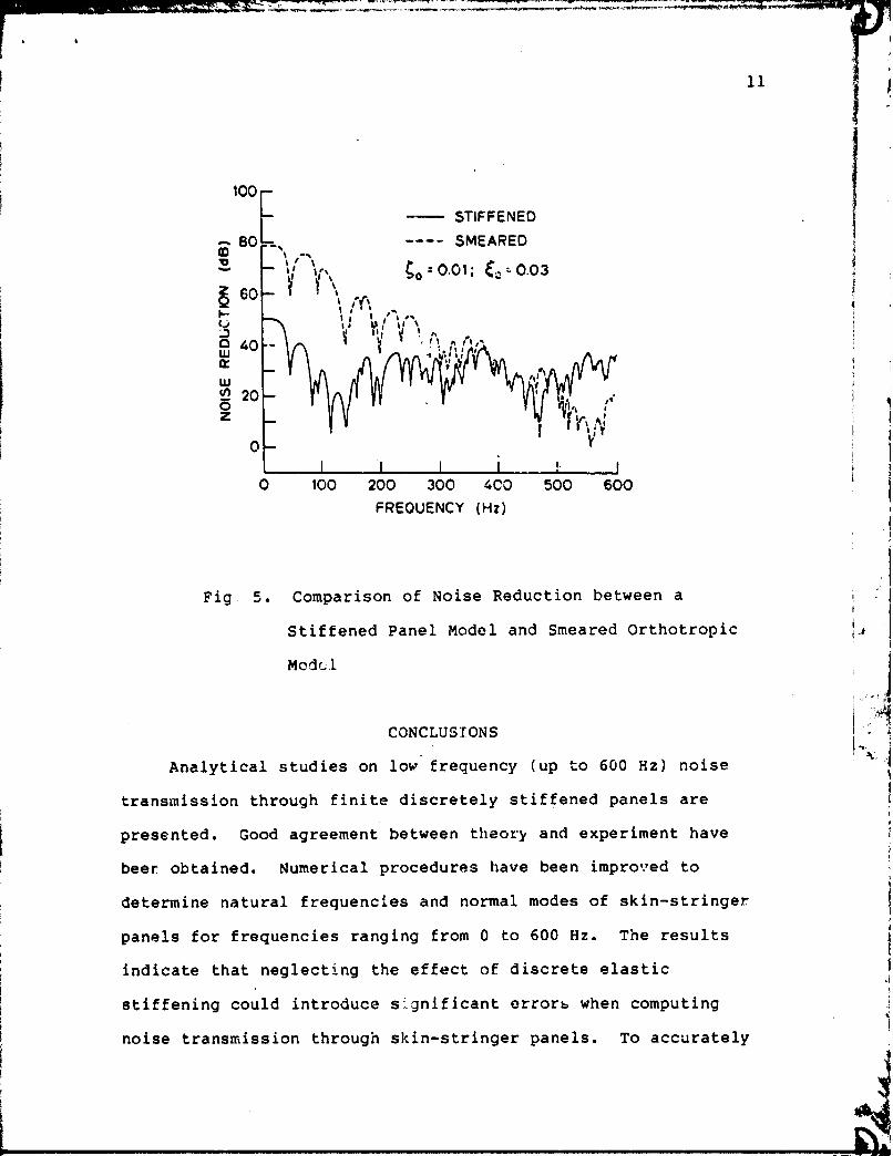
Fig 5. Comparison of Noise Reduction between a
Stiffened Panel Model and Smeared Orthotropic
Modc .l
CONCLUSIONS
Analytical studies on low frequency (up to 600 Hz) noise
transmission through finite discretely stiffened panels are
presented. Good agreement between theory and experiment have
beer obtained. Numerical procedures have been improved to
determine natural frequencies and normal modes of skin-stringer
panels for frequencies ranging from 0 to 600 Hz. The results i indicate that neglecting the effect of discrete elastic 1
.i
stiffening could introduce s:gnificant errors when computing 5 1
noise transmission through skin-stringer panels. T o accurately

evaluate the effect of low frequency attenuation in interior
noise when adding damping, stiffening, or mass treatments to the
I
I vibrating sidewall, the dynamic interaction between panel and
stiffeners should be included.
Transfer matrices for stiffened sandwich panels have been
developed. It is demonstrated that for thin samdwich panels the
sixth order equations can be reduced to a iourth order system
with only minor effect on the numerical results. considered.
1 However, even thin sandwich panels could providc a significant
I amount of energy dissipation due t-o damping in the core. It is
shown that sandwich panels, while providing the same stiffening
benefits as equivalent elastic panels, can thus significantly
C reduce interior noise levels. i
2. M.-T. Chang, "Noise Transmission Through Stiffened
Curved Panels", 1981
ABSTRACT
Presented here is the theory and solution of sound
transmission into a semicylindrical enclosure through an
elastic discretely stiffened curved panel. The transmitted
sound is calculated by solving the coupled acoustic-struc-
tural equations using a modal analysis. The modes and the
natural frequencies of the curved stiffened panels are esLI-
mated by the finite element-strip method while the acoustic
modes are those of a semicylindrical enclosure. Num~rical
results include spectra of the interior sound pressure due

to w h i t e n o i s e ,
i n p u t s .
t u r b u l e n t boundary l a y e r and p r o p e l l e r
1 3
n o i s e
HIGHLIGHTS
The geometry of a s e m i - c y l i n d r i c a l a c o u s t i c e n c l o s u r e and o f
a c u r v e d and d i s c r e t e l y s t i f f e n e d p a n e l a r e shown i n F ig . 6. The
a c o u s t i c s p a c e o c c u p i e s a volume V=nRL and is s u r r o u n d e d by s u r -
f a c e S of which t h e p o r t i o n SF is f l e x i b l e , w h i l e t h e r e m a i n i n g
s u r f a c e s are r i g i d . The curved p a n e l shown i n Fig . 6 is s t i f -
f e n e d by t w o d i s c r e t e s t r i n g e r s spaced a t e q u a l i n t e r v a l s and i t
is assumed t o be s i m p l y s u p p o r t e d around t h e e d g e s . To show t h e
e f f e c t of d i s c r e t e s t i f f e n i n g on n o i s e t r a n s m i s s i o n , c o m p a r i s o n s
o f i n t e r i o r sound n r e s s u r e l e v e l s ( S P L ) a r e made between t h e
cu rved s t i f f e n e d p a n e l s , e q u i v a l e n t c u r v e d p a n e l s i n which t h e
s t r i n g e r s a r e assumed t o be r i g i d , and "smeared" c u r v e d p a n e l
where t h e dynamic p r o p e r t i e s o f s t r i n g e r s a r e "smeared" i n t o a n
e q u i v a l e n t s k i n . I n Fig. 7 , r e s u l t s a r e shown f o r a d i s c r e t e l y
s t i f f e n e d p a n e l and s i n g l e p a n e l s ( t h r e e p a n e l s ) which a r e t a k e n
to be s i m p l y s u p p o r t e d on a l l edges . S i n c e t h e s t r i n g e r s a r e
assumed to be r i g i d , t h e c o u p l i n g e f f e c t s between a d j a c e n t p a n e l s
a r e removed and e a c h p a w l v i b r a t e s i n d e p e n d e n t l y . S i n c e a l l
t h e s e i n d i v i d u a l p a n e l s a r e i d e n t i c a l , s t r u c t u r a l r e s o n a n c e s o f
a l l p a n e l s o c c u r a t t h e same f r e q u e n c y . However, a l a r g e r number
of modes a r e e x c i t e d f o r s t i f f e n e d p a n e l s o v e r t h e s e l e c t e d
f r e q u e n c y range . S i n c e t h e s t r i n g e r s a r e a l l o w e d to r o t a t e and
d e f l e c t , s t r o n g e r c o u p l i n g is o b s e r v e d ' b e t w e e n t h e a c o u s t i c modes
and s t r u c t u r a l m o t i o n s r e s u l t i n g i n h i g h e r i n t e r i o r SPL when

i compared with the noise transmitted by single panels. These i
! I
1 results indicate that significant errors might be introduced if I I
11
the elastic stringers are replaced with rigid type supports.
The interior SPL for a discretely stiffened panel and an ! i (I
unstiffened curvzd single panel are given in Fig. 8. The
geometric and material properties of the unstiffened panel are
taken to be the same of the stiffened panel but with the
stringers removed. The dynamic behavior of such a panel can
represent a "smeared" model where the dynamic properties of
stringers are averaged out into an equivalent skin. The results
shown in Fig. 8 indicate that such an idealization could lead to
significant differences in noise transmission between discretely 1
4
stiffened panels and unstiffened panels. In view of the results I
presented, noise transmission through l~calized panel units
should accol~nt for the actual modal shapes and t!ie corresponding
a) Semicylindrical Acoustic Enclosure

b) Geometry of Curved and Discretely Stiffened Panel
Fig. 6. Semicylindrical Acoustic Space and Panel Geometry
s t i f f e n e d panel
,,,--- s i n g l e panels
panel resonance;
Fig. 7. Transmitted Noise Through a Stiffened Panel and a
Single Panel (R = 78.74 in.)

" - - -"- . - --".p---"- -- *---.------, - -,.--- "I---- .-- . x r l ' .+ -.---.* -) r ' . I
16
- stiffened panel ,,,,, unstiffened panel
panel rescnance 0
30 - 20 .! I m m . . 8 A A 1
0 1 0 0 200 300 6 0 500 600 700 800 900 1000
FREOUENCY (Hz)
Fig. 8 . Transmitted Noise for a Panel With and Without
Discrete Stiffening (R = 7 8 . 7 4 )
CONCLUSIONS
Analytical studies of noise transmission through single
p a n t l s and curved discretely stiffened panels into a
v -:~~icylindrical enclosure are presented. Procedures for
estimating the modes and frequencies of curved skin-stringer
panels are given utilizing the finite element-strip method. Good
agreement between the transfer matrix approaches and the finite
elosent strip method was reached when calculating the modes and
frequencies. The coupling for a vibrating panel due to the

1 aerodynamic surface flow and the back-up cavity pressure was
I.: 5
investigated. It was found that their effects are negligible on f t
I sound transmission and thus can be eliminated from formulation. ! I
Pressurization of the cabin tends to increase the stiffness of j 1
the vibrating panels, which cen alter the noise transmission 4 *
characteris tics in the low frequency region. L
E
When computing noise transmission through curved skin- i stringer panels, the results indicate that neglecting the effect
of discrete stiffening can introduce significant errors. For j i lower frequencies, the noise transmission is also sensitive to
the radius of the semicylindrical enclosure. When the input is
propeller noise, the interior noise is dominated by distinct
peaks due to the blade passage harmonics. The acoustic absorp- 4 i Z
tion at the interior walls can also have a positive effect on i i I
noise attenuation by suppressing the acoustic resonances. I
3. H.-K. Hong, "Nonlinear Response and Noise Transmission
of Double Wall Sandwich Panels," 1982
ABSTRACT
An analytical study is presented to predict the non-
linear response of a double wall sandwich panel system
subjected to random type loading. Viscoelastic and non-
linear spring-dashpot models are chosen to characterize the
behavior of the core. The noise transmission through this
panel system into an acoustic enclosure of which the interi-
ors are covered with porous absorption materials is deter-

- ---- -___n . ~ - T = T - - - - ---..- --- r4 :I I
I 1
i I mined. The absorbent boundary conditions of the enclosure
I are accounted for by a two-step transformation of the
boundary effect into a wave equation which governs the
acoustic pressure field inside the enclosure. The nonlinear
panel response and interior acoustic pressure are obtained
by utilizing modal analyses and Monte Carlo simulation
techniques. Numerical results include the response spectral
densities, root mean square responses, probability density
function histograms, crossing rates, and noise reduction.
.It is found that by proper selection of the dynamic paramet-
ers and damping characteristics, the structural response and
noise transmission can be significantly reduced.
HIGHLIGHTS
The results presented herein correspond to a rectangular
acoustic enclosure and a double sandwich panel system shown in
Fig. 9. It is assumed that noise enters only through the double
wall panel. The top plate of the double wall construction is
exposed to a uniformly distributed stationary and Gaussian random
pressure. The large deflection theory allows for nonlinear de-
formation of the two aluminum face plates. The core material is
taken to be relatively soft so that dilatational motions can be
included. A nonlinear stiffness and nonlinear damping model is
used for the core. The dimensions of the double wall panel and
the e~closure are L, = 20 in., Ly = 10 in., a = 72 in., b = 52
in., d = 50 in., h, = 1 in. The panel is located at z = 0, a. =
26 in., and bo = 21 in. The structural response is computed at

the center of the plate and the transmitted noise is calculated
at x = 36 in,, y = 26 in., and z = 10 in.
Shown in Fig. 10 are segments of the simulated time history
of the input random pressure and the deflection response time
histories of the top and bottom plates. The response of the
bottom plate is linear (hg = 0.064 in. ) while the response of the
tope plate is nonlinear (hT = 0.032 in. ) . The noise reduction
for different top plate thicknesses is shown in Fig. 11. For the
calculation of noise transmission into the enclosure, it was as-
sumed that a layer ( lin.) of absorption material was applied
uniformly on all the interior surfaces of the s i x walls. The
results presented in Fig. 11 illustrate significant differences
of noise transmission for linear and nonlinear panel motions.
For hT = 0.064 in., the top panel response is linear and distinct
resonant peaks are observed at the natural frequencies of the
double wall system. However, when the response reachss the non-
linear range (hT = 0.032 in. ana hT = 0.016 in.), the resonant
peaks are suppressed above the fundamental mode. The resonant
frequencies are now functions of the deflection amplitude. It
should be noted that by decreasing the thickness of t: s top
plate, the surface density of the double wall construction is
reduced. Thus, favorable gains in noise reduction can be
achieved for a smaller amount of added weight fcr a design con-
sisting of a thin top plate (nonlinear response) and a thicker
bottom plate.

I Bottom ?late h~
Fig. 9 . Geometries of a ) A c o u s t i c E n c l o s u r e and
b ) Double Wall Sandwich Pane l System

TIME. src
---
w T
in.
TIME, sac
Fig. 10. Time Histories of Simulated Input and Plate
-- hT = 0.016 in.
-.-- = 0.032 in.
Responses
-1oL-- ---.., ,.# t 6
0 100 200 3 0.0 400 500
FREQUENCY, Hz
Fig. 11. Noise Reduction for Different Top Plate Thicknesses

CONCLUSIONS
An analytical model has been developed to predict the
sonlinear response of a double wall sandwich panel system sub-
jected to random type loading. The r,,>ise transmission through
this coupled panel system into an enclosure of which the inter-
iors are covered with porous absorp2ion materials has been
obtained. The results i~dicate that the response and noise
transmission is strongly dependent on the geometric and material
properties of the double wall sandwich construction. The deflec-
tioii response of the bottom plate and, in turn, the noise trans-
mission into the acoustic enclosure can be controlled by the
proper selection of the core stif fnes and top plate thickness.
For a soft core and nonlinear response of the top plate, no
distinct resonance peaks were observed at frequencies above the
fundamental resonanc5 frequency of the coupled system. By in- I
creasing damping at the core, the response peak at the funda-
mental frequency can also be suppressed. This suggests that the A.
viscoelastic damping factor of the core should be large in the x, .
vicinity of the fundamental natural frequency of the coupled
system.
A better noise reduction is achieved for a core with a light
mass than for a core with a heavy mass. Such an observation is
contradictory to that of a single panel construction where more
added weight is considered to be beneficial to noise attenua-
tion. However, for a double wall construction, inertia coupling
between the top and bottom plates is introduced through the
core. A heavier core tends to induce strcnger coupling and

larger response of the bottom ?late.
The effect of nonlinear stifCness and nonlinear damping of
the soft core on noise reduction are in general favorable, but
the contributicns are not very iarye. The absorption materials
can De used very effectively to suppress acoustic resonances.
Since the added damping and mass of these materials to the
flexible panels are very small, their effect on the structural
response is negligible.
4. D.A. Bofilios, "Response and Noise Transmission of
Double Wall Circular Plates and Laminated Composite
Cylindrical Shells," 1985.
ABSTRACT
An analytical study is presented to predict the response
and noise transmission of double wall circular plates and
double wall laminated co~nposite fiber reinforced cylindrical
shells to random loads. The core of the double wall con-
struction is taken to be soft so that dilatational motions
can be modeled. The analysis of laminated shells is simpli-
fied by introducing assumptions similar to those in khz
Donnell-Mushtari theory for isotr~pic shells. The theoreti-
cal solutions of the governing acoustic-structural equations
are obtained using modal decomposition and a Galerkin-like
procedure. Numerical results include modal frequencies,
deflection response spectral densities and interior sound
pressure levels. From the parametric study it was found

that by proper selection of dynamic parameters, viscoelastic
core characteristics and fiber reinforcement orientation,
vibration response can be reduced and specific needs of
noise attenuation can be achieved.
HIGHLIGHTS
The numerical results presented herein correspond to the
double wall sandwich shell and circula. ?late , tern shown in
Fig. 12. The inputs to this system are eitht, f o ~ m l y distri-
buted random pressure or random point loads as presented in ~ i g .
13. The following set of parameters are selected for the
study: The dimensions of the double wall shell are L = 25 ft., R
= 58 in., h, = 2 in. The shell response is computed at x = L,/2
and 0 = 4S0. The thicknesses of the external and the inter~al
shells are hE = 0.032 in. and hI = 0.1 in. The stiffness and
material density of the core arc k3 = 4.17 lbf/in3 and
P, - 3.4 x lbf - sec2/in4. The outer shell consists of
three lamina2 while the inner shell is com~osed of ten laminae.
Fiberglass and graphite fibers are used to reinforce the Plcx-
iglass material. The ratio of fibers volume to the Plexigla~s
volume is 0.2. The fiber orientation is prescribed by an-
gle a (Fig. 12). The elastic moduli, Poisson's ratios and ma-
terial densities are Ef = 7.75 x lo6 psi vf = 0.33, pf = 0.0002
1bf - sec2/in4, eg = 10.5 x lo7 psi v = 0.33, pg = 0.00015 ibf - II
sec2/in:, Ep = 2.35 x 10' psi, v P
0.35, pp = 0.00011 lbt-sec
4 where f,g,p represent fiberglass, graphite and plexi- in
glass, respectively. The fiber reinforcement (same pattern is

used f o r i n t e r n a l and e x t e r n a l s h e l l ) is 3 r r a n g e d a s f o l l o w s :
1st l a y e r f i b e r g l a s s , 2nd l a y e r g r a p h i t e , 3 r d l a y e r f i b e r g l a s s !
and -so on. For t h e aluminum s h e l l , Ea = 10.5 x l o 6 p s i ,
v = 0.30, pa 4 = O.JC0254 l b f - s e c 2 / i n . a
The v i s c o u s damping c o e f f i c i e . . c s CE and CI a r e e x p r e s s e d i n
E I terms of modal damping r a t i o s Fmn and Fmn c o r r e s p o n d i n g t o t h e
e x t e r n a l and i n t e r n a l s h e l l s r e s p e c t i v e l y . Numerica l r e s u l t s a r e
o b t a i n e d f o r c o n s t a n t v a l u e s of modal damping. Damping i n t h e
s o f t 3re i n i n t r o d u c e d t h r o u g h t h e loss f a c t o r 9, f o r which
v a l u e s r a n g i n g from 0.02 t o 3.1 a r e s s l e c t e d .
e i The i n p u t rand..'.. . p r e s r 6 1 r e s p',pi, and p o i n t s l o a d s F j , F j
( j 1,2) are a s s u a e d t o be c h a r a c t e r i z e d by t r u n c a t e d G a u s s i a n
w h i t e n o i s e s p e c t r a l d e n s i t i e s
I 8 .41 ( p . i ) 2 / ~ ~ 0 < f < 1000 Hz
s e , i = { P P
(1) 0 o t h e r w i s e
0 < f < l O O G Hz ! 2 )
^ + I
p.' o t h e r w i s e
7
t
The s p e c t r a l d e n s i t i e s g i v e n i n E q . 1 c o r r e s p o n d t o a 130 dB i sound l e v e l . The random p o i n t l n a d s were l o c a t e d a t xe = xle = i
e 2 i = soa.
The d i m e n s i o n s of t h e d o u b l e w a l l p l a t e s l o c s t e d a t x = O f L
a r e t a k e n t o be RP - 58 i n . , h: = hs. The t h i c k n e s s e s o f t h e in-
n e r and o u t e r p l a t e s a r e h; = % = 0.25 i n . The s t i f f n e s s and

material density of the core are the same as in the shell system,
i.e., k, = 4.17 1bf/in3 and Ps = 3.4 x 10 -6 lbf - secZ/in4. ~ o t h
end plate systems are composed of aluminum, with elastic moduli
2 g T = E ~ = 10.5 x lo6 lbf/in, Poisson's ratios v T = v = 0.3 and B
material densities pT = pa = 0.000259 lbf - sec2/in4. The
viscous damping coefficients CT and CB are expressed in terms of
modal damping ratios cT and cB corresponding to the outer (top) sq sq
and inner (bottom) plates respectively. The loss factor account-
: ~g for damping in the soft core of the double wall plate systems
is taken to be gs = 0.02. The input random pressures pT, pB, a.nd
T B the point loads P , Pj (j = 1,2) was assumed to be character- j
!zed by truncated Gaussian white noise spectral densities.
0 < f < 1000 Hz ( 3 )
otherwise
0.84 lbf2/~z 0 < f < iOOO Hz
S P ~ pB = I (4)
j' j 0 otherwise
Numerical results are presented for noise transmitted and
noise generated by vibrations of the cylindrical shell and cir-
cular plate system. However, the vibrations and n'oise trens-
mission of the shell and circular plates are assumed to be inde-
pendent. Then, tne total transmitted ncise into the enclosure by
the shell and the end plates can be obtained by superposition of
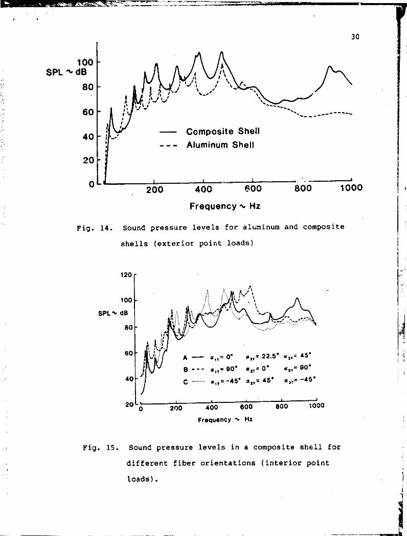
the individual contributions. The sound pressure levels
generated by aq alurt!inum and fiber reinforced laminated shells
due to point load ac Jn are given in Fig. 14. As can be

observed from these results, the noise levels generated by a
composite shell are higher at most frequercies than the noise
levels of an aluminum sheil. The mass of the composite shell is
about one-half of the mass of the aluminum shell. However, the
composite shell is much stiffer than aluminum shell. The effect
on noise transmissioc due to fiber orientation is illustrated in
Pig. 15. The fiber orientation of the three layers (Fig. 12) of
the exterior shells is described in Fig. 15. The fiber
orientation for the ten layers of the interior shell are: ( A )
0'1 22.S0, 4S0, 4S0, 22.S0, 0°, 90°, 90°, 90°,900, (B) go0, 0°,
90°, 0°, 90°, 0°, 90°, 0°, 90°, Oaf (C) -4S0, 4Sor -45O, 4S0,
-4S0, 4S0, -45". 4Z0, -4S0, 45'. These results indicate that
noise transmission through a composite shell is a function of
reinforcing fiber orientation. The interior noise levels might
be tailored to meet specific needs by selecting a suitable fiber
orientation of a rnultilayered shell. However, the transmitted
noise is a function of frequency and only specific frequency
bands might be affected.
The interior sound pressure levels at x = L/2, r = 23 in.,
and 0 = 4 5 ' due to ncine transmitted by fiber reinforced
composite shell and dodble wall end plate iocated at x = L are
shown in Figs. 16 and 17. In both of these cases, the end plate
located at x = 0 is assumed to be rigid. As can be seen from
these results, the noise transmitted by the end plate is primari-
ly low frequency (below 200 Hz) while noise above 200 Hz is domi-
nate by the shell motions.

CONCLUSIONS
An analytical model has been developed to predict vibration
response and-noise transmission of double wall circular plates
and double wall laminated composite shells to random inputs. Re-
sults indicate that the shell response is strongly dependent on
damping characteristics of the shell material and che core, loca-
tion of the point load action, and reinforcing fiber orizntation
of the different laminae. In general, the response levels for a
composite double wall shell are lower at most frequencies than
those of an equivalent aluminum construction. The vibration re-
sponse of the end caps (circular plates) are predominately low
frequency with the largest peak occuring at the fundamental mode.
The interior noise is strongly dependent on damping char-
acteristics of the shell and the core, location of the 2oint load
action, fiber orientation of the different laminae and well ab-
sorption of the interior walls. A fiber reinforced composite
double wall shell tends to generate more noise than an equivalent
aluminum shell. This is due to the fact that the mass of the
composite shell is about one half of the mass of the aluminum
shell and increase of the modal frequencies of the stiffer com-
posite shell could induce different coupling of structural-
acoustic modes. The noise transmitted by the end caps is pre-
dominantly low frequency. Thus, neglecting noise transmitted by
the end caps could underestimate interior sound pressure levels
for the low frequency region. Furthsrmore, by a proper selection
of structural damping, reinforcing fiber orientation, acoustic
absorption and core stiffness, a significant amount of lower re-

sponse and higher noise attenuation can be achieved by a design
consisting of double wall laminated fiber re; nf orced composl te
shells and a soft viscoelastic core.
P O D
b) circular end plates
a) con~posite shell
Fig. 12 Goometry of double wall shell and end plate system
L L - I
a) shell
Fig. 13 Random point loads
b) circulax plates
SPL - 5.- -----------
- Composite Shell ;I - I - - - Aluminum Shell
I - , . .- / 200 400 eoo 800 1000
Frequency - Hz
Fig. 14. Sound pressure levels for aluninum and composite
shells (exterior point loads)
100 - SPL - dB
80 -
60 -
40 -
Frequency + Hz
Fig. 15. Sound pressure levels in a composite shell for
different fiber orientations (interior point
loads) .

I N P U T : U N I F O R M P R E S S U R E
SPL dB
100
I I 1 1 I I - 1 I I 1
0 200 400 600 800 1000
F R E Q U E N C Y , H Z
r T O T A L I N T E Q I O R N O I S E
F R E Q U E N C Y , H Z
Fig. 16 Sound p r e s s u r e l e v e l s due to n o i s e t r a n s m i t t e d
by the s h e l l and end p l a t e s (uniform p r e s s u r e i n p u t )

120 --.---- INPUT: POINT LOADS s n u L - mD PLATES
:::, S P L
I . , . , . dB 4 : : :
i : j : : : %,. , . :, :. I '. . . * . ,". . . , . . ..-.
.-.. ._ : . --. -. _.--___,.---. __._---- - - _ _ -
40 I I 1 1 I
0 I I
200 I
400 I
600 I
800 1000
F R E Q U E N C Y , H Z
SPL 8ol
40 I I 1 I I
0 I I
200 I
400 1
600 1
800 1000
F R E Q U E N C Y , H Z
Fig. 17 Sound pressure levels due to noise transmitted by
the shell and end plates (point load inputs)

- - - -.-.,* _ " " --. - Ff, -'- I -
L - -
3 3
5.0 RESEARCH HIGHLIGHTS
The following is a brief description of research highlights
of the work sponsored by this grant from 1976 to 1985. A more .
detailed account of other accomplishments can be found in the
numerous technical articles listed in Sec. 3.
5.1 Noise ~ransmission Into Small Rectangular Enclosures
5.1.1 Elastic Plates
The objective of this work was to develop an analytical mo-
del to predict the noise transmitted through a rectangular elast-
ic plate into an otherwisa hard-walled acoustic cavity. The ma-
jor new analytic contribution here is the consideration of cases
in which only P portion of one cavity wall is flexible. Nonover-
lapping, independently vibrating panels can be treated by super-
position of solutions for a single panel for applications to air-
craft noise transmission. The plate is driven by an external
noise pressure which is assumed to be a stationary random pro-
cess, and the force exerted by the interior acoustic pressure on
the plate is also taken into account. The plate displacement and
the interior acoustic pressure are obtained in terms of the na-
tural modes of the and cavity and are ultimately expressed
in terms of spectral density functions.
A great deal of information on noise transmission can be
gained through a study of simple structural and acoustic geo-
metries. For application to aircraft interior noise, these mo-
dels could serve as baseline considerations where the key struc-
tural and acoustic parameters are accounted. Aircraft sidewalls

are gencraliy z>mposed of many individual panels stiffened by
stringers and frames. In many cases these individual panels can
be assumed to vibrate independently of each other, the total in-
terior noise pressure being determined by superposition as if
each panel were moving in an otherwise rigid wall.
Figure 18 illuztrates the rectangular enclosure-panel
geometry. The panel location is described by position coordi-
nates xo, yo. The noise reduction values predicted by theory
were compared with experimental values at a point x = 0.1594rn, I
y = 0.193mf z = 0.127m in a cavity of dimensions a = 0.3099m, 1 i ' 1 I
b = 0.386m, d = 0.4572m. The external-pressure excitation used . i I ' I
was spatially uniform white noise.at a level of 100 dB, and the . (
* 4
aluminum panel of thickness 0.001524m occupied the entire face z I = 0 of the cavity (xo = 0, yo = 0). Figure 19 shows calculated
I
and measured 1/3-octave band noise reduction. As can be observed 1 1 1
from these results, the agreement between theory and experiment 1 :
is relatively good. Then, using the same analytical model para-
metric studies of noise transmission through elastic panels into i 1- >I
rectangular enclosures were performed. From the results ob-
tained, the following generalizations were made:
1. External pressure distribution - The specific form of the external loading can have a considerable effect on
noise reduction.
2. Plate boundary conditions - A clamped-edge plate gives
more noise reduction below its fundamental natural fre-
quency than a simply supported one. However, the noise
---- - - -. - - - - -- - - - . :*La- - - .-. -L- -
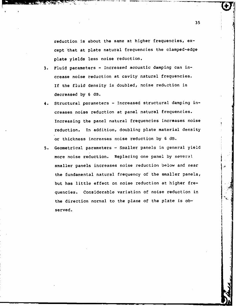
reduction is about the same at higher frequencies, ex-
cept'that at plate natural frequencies the clamped-edge
plate yields less noise reduction.
3 . Fluid parameters - Increased acoustic damping can in- crease noise reduction at cavity natural frequencies.
If the fluid density is doubled, noise red~ction is
decreased by 6 dB.
4. Structural parameters - Increased structural damping in- creases noise reduction at panel natural frequencies.
Increasing the panel natural frequencies increases noise
reduction. In addition, doubling plate material density
or thickness increases noise reduction by 6 dB.
5 . Geometrical parameters - Smaller panels in general yield more noise reduction. Replacing one panel by several
smaller panels increases noise reduction below and near
the fundamental natural frequency of the smaller panels,
but has little effect on noise reduction at higher fre-
quencies. Considerable variation of noise reduction in
the direction normal to the plane of the plate is ob-
served.

t z
Fig. 18 Cavity and panel geometry.
- 1 o j l l r l l l l l l l l l l l I 1 I I I j 10 100 loo0
11 3-octave band center frequency, Hz . r (
Fig. 19 Theoretical and experimental 1/3 octave band spectrum
of noise reduction.

5.1.2 Viscoelastic Sandwich Panels
The information available in the literature and from
ongoing research programs on interior aircraft noise indicates
that noise in many aircraft and rotorcraft exceeds acceptable
comfort limits. Since acoustic absorption materials used in -
aircraft constructions are not very effective in reducing in-
terior noise at low frequencies, new means of providing noise
attenuation at low frequencies need to be established. Interior
aircraft noise in the structural resonance range is strongly con-
trolled by the vibrational characteristics of the fuselage skin
panels. Past studies have demonstrated that a viscoelastic ma-
terial sandwiched between two elastic plates is a very efficient
way of dissipating vibrational energy. Replacing some of the
' elastic skin panels with viscoelastic sandwich constructions
should achieve additional amounts of noise reduction. Thus, an I j
analytical study of this subject has been undertaken. The pro- ,
blem geomtery of acoustic enclosure and a viscoelastic sandwich
panel is shown in Fig. 20. The dimensions of the flexible panel
were chosen from typical aircraft skin panels. The solutions for k.
noise transmission were developed for two limitjqg cases of core
stiffness. In the first case, the viscoelastic material is taken
to be very soft so that bending and shearing stresses can be ne-
glected, and the core acts merely as a viscoelastic spring. For
the sandwich construction with this soft core, the flexural vi-
bration modes are governed by the stiffness of the two face
plates, and the out-of-phase dilatational modes are controlled by
the stiffness characteristics of the viscoelastic spring. In the

second case, a stiff viscoelastic core material is used where the
bending and shearing strains in the core are important. In both
cases, the solution of the governing acousto-structural equations
are obtained by using modal expansions a r .- a Galerkl n-lj ke groce-
dure. Sinc; the boundary conditions for those equations are time
dependent, the commonly used method of separation of variables
cannot be applied to this system. The time dependence, however,
i~ removed by splitting the solution into two parts: a solution
corresponding to a nonhomogeneous differential equation with ho-
mogeneous boundary conditions and a solution on the boundary.
Following this procedure, a Fourier series solution is developed
which converges rapidly not only in tho interior acoustic space
but also on the boundary. These series have a computational ad-
vantage over the nonuniformly convergent series which usually
converge very slowly.
The numerical results presented correspond to aluminum face
plates and lightweight low modulus viscoslastic core material.
The input random pressure acting on the to^ face plate is taken
to be uniformly distributed truncatad Gaussian white noise. The
noise transmission through a sandwich construction with a soft
core is shown in Fig. 21. These results are obtained from
NT = 10 log S /S P P
(5)
where Sp is the spectral density of the acoustic pressure in the
cavity at x = O.lOZm, y = 0.152m. z = 0.254m and Lp is the
spectral density of the input pressure. The dimensions of the

acoustic enclosure and the sandwich panel are a = 0.250m, b =
0.508n. d = 0.762111. h- = h2 = 0.00051m, h3 = 0.00635111. The
coefficient $ indicates diffecent values of damping 10,s; factor
in the core. When $ = 0, damping is only present in the face
plates and not in the core. As csn be observed from these re-
sults, a strong peak occurs at the first dilatatiot!al modal frs-
quency (401 Hz) when $ = 0. The noise transmission characterist-
ics of elastic panel ( p > 0) with soft core are similar for fre-
quencies up to about 250 Hz and above 600 Hz. However, in the
intermediate frequency range, structural modes corresponding to
dilatational vibrations have a significant effect on noise trans-
mission. At the frequency of the first dilatational mode, a pa-
nel with a soft viscoelastic crre can achieve about 28 dL more
noise reduction. These results indicate that noi3e transmission
into the enclosure is dominated by flexc- modes for frequencies
below 250 Hz, by dilatational and acoustic modes in the frequencv
region 250 to 500 Hz, and by acoustic modes above SO0 Hz.
For the viscoelastic sandwic!; panel with a hard core, damp-
ing in the face plates was assumed to be negligible in comparison
to damping in the core. A comparison of noise transmission by
elastic and viscoelastic panels is shown in Fig. 22. The mass of
the elastic panel was adjusted to be equivalent to the mass of
the viscoelastic sandwich panel. Modal damping for the elastic
panel was calculated from

where a ara modai coefficients and umn arc the natural fre- mn 1 '
4 quencies of the elastic plate. The results shown in Fig. 5 2 cor- t
: I
respond to a = 0.32. As can be observed from these results, 11
noise i=ansmission for an elastic panel is strongly dominated by : ! * *
structural vibrations while the noise transmisqion by a uisco- ' 1
elastic sandwich panel is dominated by acoustic cavity modes. I
Significant differences of noise transmission can be ach :ved for 1 viscoelastic cores with different values of shear modulus Go. i
An analytical study was conducted to determine noise trans- I I
mission characteristics of viscoelastic sandwich panels. The re-
suLts indicate that noise transmission by sandwich panels is
strongly dependent on thickness, damping, and material properties 1 of the viscoelastic core.
Sandwich panels with very soft viscoelastic cores transmit
noise much like elastic panels except in the frequency range
where dilatational (out-of-phase) modes are excited. About 20 dB
more noise reduction can be achieved by visco-elastic sandwich
paneis in this frequency range (300 to. 600 H z ) .
The vibration response and noise transmission of sandwich
panels with hard cores are lower when compared with equivalent
elastic panels. As much as 50 dB more noise reduction can be
achieved by viscoelastic panels at some frequencies in the low
frequency range (below 200 Hz). At frequencies above 200 Hz,
acoustic modes dominate interior n3ise for the acoustic enclosure
chose.? in this study. About 10 dB more overall noise reduction
can be gained by increasing the core Lhickness 10 times (from
O.CO25 to 0.025 m). With increasing core stiffness (from a shea.r

modulus of 2 760 00 ~ / m ~ to a s h e a r n o d c l u s o f 68 900 000 ~ / r n ~ ) ,
n o i s e r e d u c t i o n d e c r e a s e d by about 5 dB o v e r a l l .
NO l SE
2 (a ) Enclosure. (b) Viscoelastic sandwich panel.
Fig. 20 Geometry o f e n c l o s u r e and v i s c o e l a s t i c sandwich p a n e l .

20
10
ION, 0
-10
-20
V STRUCTURAL MODES 0 ACOUSTIC MODES
-43 1 I 1 I I I I I I I I
0 200 400 600 800 loo0
FREQUENCY. Hz
Fig. 21 Noise transmission by viscoelastic panel with soft
core. h j = 0.00635 m; aOOl = 0.01.
V STRUCTURAL MOMS rp r E U S ~ C In = 0.001. 0 rcousTIC Mas
NOISE -10 TRANSMISSION.
dB -20
FREQUENCY. Hz
Pig. 22 Noise transmission by elastic 2nd viscoelastic panels 1 : with hard cores. h3 = 0.00635 m; p = 1.0.

5.2 Noise Transmission Through Stiffened Panels
Efforts to reduce cabin noise levels have created a need for
better understanding of the interaction between the aircraft
fuselage vibrations and the interior noise in the cabin. For
example, effective utilization of add-on treatments, such as
honeycomb panels, constrained layer damping, tuned damping and
non-load carrying mass, requires detailed knowledge of the dynam-
ic characteristics of multi-span structure of which many trans-
portation vehicles are constructed. Most analytical studies on
noise transmission into aircraft have been directed toward using
"smeared" orthotropic plates or shells and individual panels.
The effect of discrete stiffeners on the vibration and noise
transmission was not considered. The objective of the present
research was to develop analytical models capable of predicting
the noise transmitted through flat and curved discretely stif-
fened panels. A brief description and highlights of this pro-
cedure was presented in Sec. 4. In what follows, key results of
noise transmission through discretely stiffened pznels are pre-
sented for laboratory models and light aircraft tested at groucd
conditio~s.
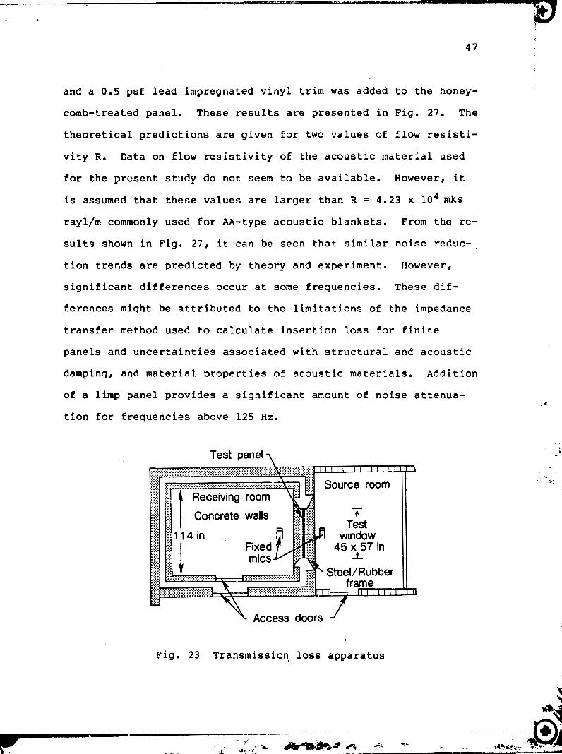
5.2.1 Transmission Loss Apparatus
The transmission loss apparatus located at NASA, Langley
Research Center, ANRD is designed around two adjacent reverberant
rooms of which the receiving room is acoustically and structural-
ly isolated from the rest of the building (Fig. 23). The test
specimen is mounted on a heavy, stiff frame which is installed as

a partition between the two rooms. In the source room a diffuse
noise field is produced by two reference sound power sources.
Noise reduction is defined as the difference between the measured
sound pressure levels of the microphones in the source and
receiving rooms. The test "window" between the two rooms can
accommodate test specimens that are similar in size to light air-
craft fuselage side-walls. These specimens can range in size up
to about 1.15m x 1.46~1. Experiments were carried out by NASA to
measure noise transmission through a stiffened panel built ac-
cording to the specifications of an actual light turboprop air-
craft. In addition, laboratory study was undertaken to define
the noise transmission variables for a number of add-on treat-
ments.
A theory based on a normal mode approach was developed to
predict noise transmission through various panels installed in
the noise transmiss ion loss apparatus. The random pressure act-
ing on the panel was modeled as a reverberant acoustic field for
which the joint nodal acceptances were calculated. The low fre-
quency noise transmissi~n (up to about 125 Hz) was calculated
using a "smeared" orthotropic panel model. For the intermediate
frequency range of 125 - 800 Hz, discretely stiffened panels were used for which the modes and modal frequencies were obtained by
transfer matrix or finite element strip methods. Single panel
model was used for those cases where a flexible panel was sup-
ported by heavy frames. The emphasis of the analytical study was
on low frequency noise transmission (up to about 800 Hz).
The insertion losses due to add-on treatments which have no

marked e f f e c t on t h e s t r u c t u r a l v i b r a t i o n s ( p o r o u s a c o u s t i c
m a t e r i a l s , n o i s e b a r r i e r s , and t r i m p a n e l s ) were c a l c u l a t e d by
t h e impedance t r a n s f e r method. Numerica l p r o c e d u r e s were de-
v e l o p e d f q r t h e m u l t i - l a y e r e d t r e a t m e n t s shown i n Fig . 24. The 1
I li
sound p r e s s u r e l e v e l s i n s i d e t h e e n c l o s u r e were c a l c u l a t e d f rom 1
SPL 1 t r e a t e d = SPL 1 u n t r e a t e d - ATLO - ATL
where ATL a r e t h e n o i s e losses due t o t r e a t m e n t s d i r e c t l y a t - 0
t a c h e d t o t h e a i r c r a f t s k i n (honeycomb p a n e l s and damping t a p e )
and ATL a r e t h e i n s e r t i o n losses due t o a l l o t h e r t r e a t m e n t s
( p o r o u s b l a n k e t s , septum b a r r i e r s , t r i m ) . i 3
A s a f i r s t s t e p i n t h e v a l i d a t i o n o f t h e t h e o r y , p r e d i c t i o n s 1 t i
and tests were per fo rmed f o r a s t i f f e n e d p a n e l shown i n Fig .
25. The n o i s e i n p u t s were measured a t s e v e r a l p o s i t i o n s close t o
t h e p a n e l s u r f a c e by a s t a t i o n a r y microphone. A s ? a t i a l l y
a v e r a g e d v a l u e of s o u r c e p r e s s u r e was s e l e c t e d f o r n o i s e reduc-
t i o n c a l c u l a t i o n s and measurements. T r a n s m i t t e d n o i s e was mea-
s u r e d by a s t a t i o n a r y microphone l o c a t e d a t a b o u t t h e m i d d l e o f
t h e p a n e l and 66 i n . from t h e p a n e l s u r f a c e .
The a n a l y t i c a l c a l c u l a t i o n s were o b t a i n e d f o r a c o n s t a n t
s t r u c t u r a l modal damping r a t i o Co and a c o u s t i c modal damping
a R i jk = aO ( W ,/ui jk). Fo and aO a r e t h e damping c o e f f i c i e n t s o f
t h e fundamenta l modes, o i jk t h e a c o u s t i c modal f r e q u e n c i e s , w
t h e lowest modal f r e q u e n c y i n t h e r e c e i v i n g room, and i , j , k t h e
modal i n d i c e s . For t h e p r e s e n t s u t d y , it was assumed t h a t CO =
9.03 f o r t h e u n t r e a t e d s i d e w a l l p a n e l and 0.05 f o r t h e csse where
, - 2. .-a -4+ .k _ _ - _ _ _ -

honeycomb panels are attached to the interior surface (receiving
room side) of the skin. These damping coefficients are taken to
be representative of the overall damping which includes material,
structural, and ac~ustic radiation damping. The acoustic damping
in the receiving room a is taken to be equal to 0.005. This 0
damping model is assumed to be a simplified representation of
equivalent acoustic damping in a room with hard walls.
To investigate the effect of skin stiffening, lightweight
treatments in the form of honeycomb panels were attached to the
interior side of the skin. For this purpose, aluminum honeycomb
sandwich construction with a core thickness of 0.25 in. and a
face plate thickness of 0.032 in. was selected. The surface den-
sity of this treatment is about 0.68 psf. Fig. 26 shows theore-
tical and experimental noise reductions of the stiffened panel
treated with honeycomb. In general, the aggreement between theo-
ry and experiment is good in view of the complexities involved.
About 4-5 dB of noise attenuation is achieved in the 80-400 Hz
frequency range with the honeycomb add-on treatment. However,
for frequencies above 400 Hz, lower values of noise reduction
were measure for treated panels. The noise reduction in this
frequency range seems to be influenced by the coincidence effect
at the critical frequency. The critical frequency of a sandwich
construction composed of 0.063-in. skin, a 0.25-in. honeycomb
core, and a 0.032-in. face plate is about 1OOO Hz. However, the
presence of heavy stiffeners could reduce the critical frequency
of this panel further.
To simulate a treated sidewall, porous acoustic materials
and a 0.5 psf lead impregnated vinyl trim was added to the honey-
comb-treated panel. These results are presented in Fig. 27. The
theoretical predictions are given for two values of flow resisti-
vity R. Data on flow resistivity of the acoustic material used
for the present study do not seem to be available. However, it
is assumed that these values are larger than R = 4.23 x lo4 mks
rayl/m commonly used for AA-type acoustic blankets. From the re-
sults shown in Fig. 27, it can be seen that similar noise reduc-,
tion trends are predicted by theory and experiment. However,
significant differences occur at some frequencies. These dif-
ferences might be attributed to the limitations of the impedance
transfer method used to calculate insertion loss for finite
panels and uncertainties associated with structural and acoustic
damping, and material properties of acoustic materials. Addition
of a limp panel provides a significant amount of noise attenua-
tion for frequencies above 125 Hz.
Test panel
..... ::::: ..... .:.:.
+ "t Test
] 45 x 57 in
1 Access doors
Fig. 23 Transmission loss apparatus

Septa
LRina frames 3 Incident 8,
pressure Dd/Pr [ Honeycorn b rDamping tape
skin
natsrials
" L r i m panel pressure
Fig. 24 Sidewall representation of r n u l t i l a y e r e d add-an
F i g . 2 5 Stiffened sidewall pane? used for noise
t r a n s m i s s i o n study

A Experiment
NR, A dB *(I A
Frequency, Hz
F i g . 26 ~ o i s e r e d r n t i o n o f t h e p a n e l t r e a t e d w i t h honeycomb
A Experiment
- Theory (R = R1) ----- Theory (R = 1.5R 1 )
Skin R1 - 4.23 x lo4 mks ryal/
Frequency, Hz
F i g . 27 Noise r e d u c t i o n o f a s i d e w a l l p a n e l t r e a t e d w i t h
honeycomb, p o r o u s a c o u s t i c m a t e r i a l a n d t r i m


p a n e l s a r e modeled by s i m p l e p l a t e t h e o r y , d i s c r e t e l y s t i f f e n e d
p z n e l s by t h e t r a n s f e r m a t r i x me thods , and windows by a d o u b l e -
w a l l t h e o r y .
The n u m e r i c a l r e s u l t s p r e s e n t e d i n t h i s r e p o r t a r e n o i s e
t r a n s m i s s i o n t h r o u g h s i d e w a l l p a n e l s and t h e e n t i r e s i d e w a l l o f
t h e a i r c r a f t shown i n F i g s . 28 and 29. The c a l c u l a t i o n s a r e
o b t a i n e d f o r s t r u c t u r a l and a c o u s t i c modal damping r a t i o s
= C o ( W 10 ) and F i j k R 'mn 11' mn = Co ( W / u i j k ) . The C o and G o are
t h e damping c o e f f i c i e n t s o f t h e f u n d a m e n t a l mode', umn a n d w i j k
are t h e s t r u c t u r a l a n d a c o u s t i c r , d a l f r e q u e n c i e s , and w A is t h e
l o w e s t a c o u s t i c modal f r e q u e n c y i n t h e e n c l o s u r e . F o r t h e p r e -
s e n t a n a l y t i c a l s t u d y , it was assumed t h a t C O e q u a l s 0 . 0 1 f o r
s i n g l e p a n e l s , 0 .03 f o r honeycomb- t r ea t ed p a n e l s , 0 .04 f o r damp-
i n g t a p e t r e a t e d p a n e l s and 0.05 f o r t h e ~ l e x i ~ l a s windows. The
damping c o e f f i c i e n t CO was assumed t o be e q u a l t o 0 .03 f o r a
l i g h t l y t r e a t e d c a b i n and 0.06 f o r a heavy t r e a t e d c a b i n . Wal l
a b s o r p t i o n was brovided t h r o u g h a p o i n t impedance model .
E x p e r i m e n t s were c a r r i e d o u t f ~ r n o i s e t r a n s m i s s i o n estima-
t i o n t h r o u g h l o c a l i z e d r e g i o n s and t h e e n t i r e s i d e w a l l . The l o -
c a l i z e d i n p u t s t o t h e s i d e w a l l p a n e l s and windows were g e n e r a t e d
by a n a c o u s t i c g u i d e shown i n F i g . 31. The b a s i c f e a t u r e s o f t h e
a c o u s t i c g u i d e d e s i g n i n c l u d e a h i g h q u a l i t y a p e a k e r a n d a s l o w l y
d i v e r g i n g r e c t a n g u l a r d u c t . To m i n i m i z e n o i s e l e a k a g e f rom t h e
i t l t e r i o r e n c l o s u r e o f t h e g u i d e , two layer^ o f n o i s e b a r r i e r s ,
e a c h w i t h a s u r f a c e d e n s i t y o f 1 l b / f t 2 , were added to t h e
e x t e r i o r s u r f a c e s o f t h e g u i d e . Between t h e d u c t and t h e s i d e -
w a l l o f t h e a i r c r a f t , s o f t i n s u l a t i o n m a t e r i a l ( f o a m ) , r a n g i n g i n

thickness from about 2 in. to 4 in. was installed around the
periphery of the guide. The present design with duct dimensions
of either 20 in. x 20 in. or 30 in. x 30 in. can be used to
generate acoustic inputs for small panels, windows, and larger
areas of discretely stiffened panels. The noise-measuring syste:
includes a microphone inside the guide at about 1 in. from the
sidewall surface and a microphone inside the cabin at about 10
in. from the interior wall. Fcr laboratory study of noise trans-
mission through the entire sidewall, the acoustic inputs wc re
generated by a two-speaker setup. A relatively uniform external
noise pressure distribution over the surface cf the sidewall was
generated by the two speakers which were located at about 4 ft.
from the sidewall.
Theory and Experiment - The noise transmission through each panel unit indicated in
Fig. 30 was calculated and measured. Assuming independence of
these noise transmission paths, the total interior sound pressure
(~rlleoretical) was determined by the superposition of the contri-
butions of all panels locate on the sidewall. The noise reduc-
tion for a typical stiffened panel and the entire sidewall is
given in Figs. 32 3nd 33. Similar resuits are presented in Fig.
34 for a double-wall window. These results correspond to un-
treated conditions and an interior location at ear level in the
propeller plane and 10 in. from the sidewall. As can be observed
from these results, the agreement between theory and experiment
is relatively good in view of the complexities involved. The

53
theoretical model tends to predict lower noise reduction at some
1.;: structural modal resoname frequencies. These differences might
1 ' be attribcted to damping (structural and radiatior~) and Ideal- t i I istic mode shapes used in tba theoretical calcui~tions. I , .
1 Furthermors, the assumed spatially uniforn inputs for the the-
I oretFcal model cannot b~ accurately simulated with the present
experi~ental setup.
Experimerltal Parametric Stddy 9f Add-on Treztments - The noise transmissinn data were obtained for a variety of
aircraft sidewall treatments, These treatments include t~cneycomb
panels, damping tapes, no~load carrying mass, acoustic barriers,
multi-layered septum and trim panels. Furtherncre, noise trans-
mission through aircraft windows has been measured fcr several
conditions of different acoustic interiors. The primary .>bject-
ive of this work was to evaluate a number of candidate treatments
to be used f o ~ - the optimization of interior noise in ligh: air-
craft. Tho description of add-on treatment; is given in Table 1.
The noise reduction for l~ntrezted and treated sidewall is
given in Fig. 35. These results indicate that 4-14 dB of addi-
tional noise reduction can be achieq7ec? in the frequncy range 50-
1000 Hz with an add-on treatment composed of honeycomb, con-
strainad layer damping tape and two layers of zcoustic blank-
ets. The added surface density is about 1 lb/ft2. The rzsults
presented in Fig. 36 shown the effect of trim panel on noise re-.
duction. For frequencies above 160 H z . significant amount of
noise reduction can be achieved with a heavy trim panel iabout 1

lb/ft2i. The following conclusions were drawn from this para-
metric study:
1. An acoustic guide device can be used to generate noise
inputs over localized regions of the sidewall.
2. Interior noise levels transmitted throuqh localized
panels or windows are function of measurement position
in the cabin and conditions of treated interior.
3, Stiffening skin panels with honeycomb could provide 3-7
dB additional noise reduction. However, these gains are
functions of panel geometry, installation conditions and
frequency. The noise attenuation obtained for the en-
tire sidewall treated with honeycomb panels is less than
for some individual panels.
4. Constrained layer damping materials could provide 2-3 dB
of noise reduction. However, these increases depend on
frequency.
5. Porous acoustic blankets (2-3 laycrs) provide noise at-
tenuation for frequencies only above 300 Hz. The
insertion losses reach about 10-12dB aL 1000 iiz. I .
' 4 6. A multilayered treatment composed oi porous blankets and \
impervious vinyl septa does not provide additional noise
reduction for Erequencies up to about 500 Hz. In the
frequency range below 500 Hz, several double wall reso-
nances are observsd.
7 . Noise barriers composed of urethane elastomer and de-
coupler foam do not give noise attenuation for frequen- I 3 ' 1
i 4 J I
cies up to about 500 Hz.

8. A treatment composed of several layers of acoustic foams
does not seem to provide noise attenuation. However,
when a single layer is used as a trim panel, positive-
gains of noise reduction are achieved for frequencies
above 600 Hz.
9. A trim with a surface density of lb/f t2 panel which is
isolated from the vibration of the main structures could
provide jnsertion losses ranging from 3-20 dB for fre-
quencies 160-1000 Hz. Negative values of noise attenua-
tion were measured at the double wall resonance fre-
quency of 125 Hz.
10. An acoustic treatment for noise control in t.his aircraft
should be composed of honeycomb panels, constrained lay-
er damping tape, several layers of porous acoustic ma-
terials, and limp trim panel which is isolated for the
vibration of the main structure. Furthermore, addition-
al stiffening to window supports, some frames and lon-
gerons would need to be implemented.
Interior Noise Optimization: Theoretical Study - A detailed analytical study of noise control and cabin ncise
optirnatioil with add-on treatments was undertaken. The basic con-
cept of the analytical model is thaL of modal analysis wherein
the acoustic modes in the cabin and the structural modes of the
sidewall are accounted for. To estimate the noise losses due to
add-on treatments such as acoustic blankets, septum barriers and
trim panels, an analytical procedure based on the impedance

transfer method was used. The interior noise in the cabin was
optimized utilizing measured propeller noise inputs (ground con-
ditions) and the following computation procedure. The noise
transmitted by each panel unit was calculated for each add-~n
treatment and then for a combinatioq of several treatments. The
amount of treatments was increased until a selected target noise
level at a critical point in the cabin was reached. The treat-
ment or conbination of treatments which reduces the transmitted
noise to the selected optimization value for the least amount of
added weight was assumed to be the best treatment. An 85 dBA
overall average noise level was selected as the optimization
target for the noise transmitted into the cabin. The optimized
and baseline (untreated cabin) interior noise levels are shown in
Fig. 37. The optimized treatment includes honeycomb panels, con-
strained layer damping tape, porous acoustic blankets and rela-
tively soft trim which is isolated from the vibrations of the
main structure. The added weight of the optimized treatment is
about 1.5 lb/ft2. The distribution of the surface densities
(baseline and treated) for the optimized sidewall are given in
Fig. 38. In this procedure, it is assumed that flanking paths
can be eliminated. Based on this study, the following conclu-
s ions have been reached.
An analytical model has been developed to predict the noise
transmission into a twin engine G/A aircraft. The model has been
used to identify the airborne noise trnsmission paths and to
optimize the interior sound levels due to propeller noise in-
puts. The average cabin noise levels in the baseline aircraft 1 '
-. - -- -- - -- La;
&%**@ /, s- -- . ..'. ' 9. +iJ
reach a maximum of about 105 dBA and these levels are about 20
dBA higher than the optimization goal of 85 dBA. The results
indicate that the required noise reduction has to be achieved
mainly ic the low frequency range of 70 - 350 Hz. For the type
of aircraft considered, the first four propeller blade passage
harmonics are within this f requencv range.
The required noise attenuation has been obtained by add-on
treatments which do not involve changes in the fuselage primary
structure. These add-on treatments include lightweight aluminum
honeycomb panels, constrained layer damping tape, porous acoustic
blankets and limp trim panels. Due to the non-uniform input
pressure distribution and different structural dynamic charac-
teristics of the sidewall panels, the amount and type of treat-
ment applied to achieve the required noise reduction varies from
one panel unit to another. The study indicates that the heaviest
amount of treatment needs to be applied to those panels located
in the vicinity of the propeller plane. Of the techniques in-
vestigated, the combination of honeycomb panels and constrained
layer damping tape applied to the aircraft skin seems to promise
the required reduction in noise transmission in the low frequency
region (70 - 350 Hz). Noise attenuetion for higher frequercies
can be achieved with a double wall system composed of porous
acoustic blankets and limp trim panels which are isolated from
the fuselage vibrations. However, a heavy trim panel might not
always be beneficial for noise control since double wall re-
sonances might coincide with one of the low frequency propeller
blade passage harmonics. The optimization study indicates that

to reduce cabin noise to a satisfactory level for the least
amount of added weight, a combination of different add-on treat-
ments needs to be used. The total added weight to the aircraft
is about 75 lbs. which is about 1.1% of the take-off gross
weight. It should be noted that in achieving these values the
effect of potential flanking paths and noise entering through the
front and rear bulkheads have not been included in the analytical
model.
The analytical prediction method has been validated experi-
mentally with laboratory tests wherein all parameters could be
carefully controlled or measured. A relatively good agreement
between theoretical predictions and experimental observations in
the field under static operating conditions has been achieved for
the baseline airc'raf t.
Fig. 28 Twin-engine aircraft used in the noise optimization study

Fig. 29 Structural features of a twin-engine aircraft used for
interior noise study
0 PANEL NO.
Fig. 30 Panel Identification .for Port Side (P)

Fig. 31 Setup for laboratory noise transmission thorugh
localized reg ions
FREQUENCY, Hz
Fig. 32 Noise reduction of a stiffened aircarft panel: noise
input from an acoustic guide

30 t THEORY
-- - --EXPERIMENT
0 I - J 1 63 125 250 5Gr3 1000
FREQUENCY, Hz
Fig. 33 Noise reduction of an aircraft sidewall:
noise input from a diffuse field
50 [ -- EXPERIMENT
40 63 125 250 50d 1000 FREQUENCY, Hz
Fig. 34 Noise reduction of a double wall aircra-ft window:
noise input from an acoustic guide

....... Honey comb , _ - - -Honeycomb
2 layers
F i g . 35 The o n e - t h i r d o c t a v e n o i s e r e d u c t i o n f o r t r e a t e d
and u n t r e a t e d s i d e w a l l
damp in6
damping blanket
tape
tape

NR Honeycomb + damping tape
4 B - - - -
4 0 'Honeycomb + damping tape + 2 layers A + Masonlte panel
. . Honeycomb + damping tape + 2 layers A + noise barr ier 4101
3 0
A - porous acoustic blanket
2 0
I ! ! ! ! ! ! ! ! ! ! ! ! ! ! !
ONE-THIRD OCTAVE BAND CENTER FREQUENCIES IN Hz
Fig . 36 Noise reduction with a heavy t r i m

- - - ii 1 0 0 = a - b o l e l l ~ I OA 107 dBA --- optimlred I 0 A 88 dBA
0 e 90 added welght - 30 Id.
2 panel orea ' 29 wR. u pond a n * ( 1.15 l M q . 1 ~ ) ;L -1
honeyomb* ( 0 -56 I M a . f L ) W > 10 W
W S R 5 (dm) Ln V) W K
7 0 - Q 0 z 3 :: n z a 03 W
z t 0 0 n E I t W Z
1 1 1 1 1 ' 1 1 1 1 ,
0 I . $9 8 0 125 200 315 5 0 0 BOO 1250 25 4 0 63 100 I60 250 400 630 1000 a - unit under study
ONE-THIRD OCTAVE BAND CENTER FREQUENCIES IN HI (cpr) * ave"9e
Fig. 37 Optimized interior noise (Sidewall)
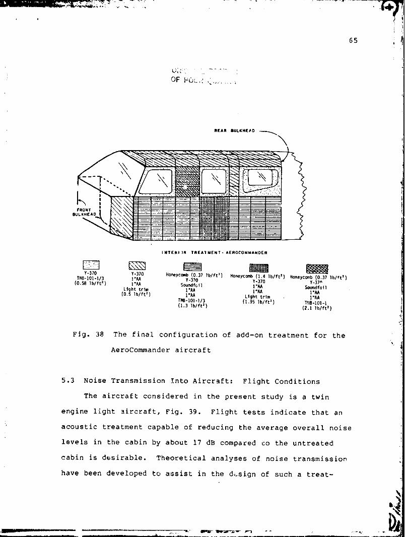
REAR @ULUHEED - \
l N l E R l I R TREAT MENT - AEROCOLOMANOER
'I Y-370
m Y-370
m Honeycmb (0.37 1b/ft1) Honeycomb (1.4 1 b / f t 2 ) Honeycmb (0.37 l b / f t 2 ) TNB-101-1/3 1 "AA Y-370
(0.58 l b / f t 2 ) 1 "M Y-370 Soundfc, i 1 Y -37n
L igh t t r i m 1 "AA I'M Swndfo i 1
(0.5 l b / f t 2 ) 1 "AA L igh t 1 "AA t r i m . I'M 118-101-1/3 (1.95 l b / f t z ) I "AA (1.3 1 b / f t 2 )
1'18-101-1 (2.1 l h l f t ' )
Fig. 38 The final configuration of add-on treatment for the
AeroCommander aircraft
5.3 Noise Transmission Into Aircraft: Flight Conditions
The aircraft ccnsidered in the present study is a twin
engine light ztircraft, Fig. 39. Flight tests indicate that an
acoustic treatment capable of reducing the average overall noise
levels in the cabin by about 17 dB compared so the untreated
cabin is desirable. Theoretical analyses of noise transmission
have been developed to assist in the d-.sign of such a treat-

ment. The basic concept of the theoretical model is that of mod-
al analysis and the acoustic impedance transfer. k similar ap-
proach described in Sec. 5.2.2 has been used for interior noise
optimization of a small twin-engine aircraft corresponding to in-
puts measured at the ground conditions. These methods have been
extended for design of noise control treatments of the aircraft
shown in Fig. 39 under flight conditions. Improved analytical
methods of noise transmission prediction through flexible panels
and double pane windows are incorporated in the present study.
The analyses are compared with test data under laboratolv snd
flight conditions.
The acoustic treatments considered in this paper include
aluminum honeycomb panels, constrained layer damping tapt porous
acoustic materials, noise barriers, limp trim panels, tuned damp- q
ers and changes in aircraft window design. This work is focused
on evaluating the advantages and disadvantages of these treat-
ments for noise control and then designing a candidate acoustic
treatment which redl~ccs noise in the cabin to a satisfactory
level.
The sidewalls of the aircraft shown in Fig. 39 are composed
of a 0.063 in. thick external skin which is stiffened by frames
and longerons and several single- and dual-pane windows. The r
exact dyr.amic analysis of such a structure is too com~licated and
a sim2lified model needs to be constructed. For the structural b f
f
model of the presen. study, Fig. 40, the aircraft sidewall is f
segmented into four stiffened skin-stringer panels, two single
panels, and six windows. The noise transmitted through other I

surfaces of the sidewall is neglected. Such a segmentation of-
t,!rs significant advantages for noise transmission path identifi-
cation and computational simplification. However, this procedure
is best applicable for the intermedizte to high frequency rany-
es. The lowest modal frequencies calculated for window unit No.
1 and stiffened panel unit No. 11 are 214 Hz and 134 i lz . Mea-
sureii~ents tend to indicate the presance of several frame-wall
mcdes in the frequency range of 48 Hz to 104 Hz. Thus, t!?e seg-
mented'st.ructura1 sidewall model does not ?( :ount for the frame-
wall modes below +he frequency of about 1 . d Ez. To deve1;p ac-
curate solutions for low frequencies, numericai techniques such
as the finite element method can 52 used. Since the A-weighted
interior noise in this aircraft is dominated by the 2nd, 3rd and
4th (152 Hz, 228 Hz, 304 Hz) prcpeller blade passage harmonics, I
I i
the idealization of the sidewall into several independent units I !
seems to be justified. 1
The external surface pressure acting on t\e aircraft is
propeller and turbulent boundary layer noise. For frequencies up c \ .I
to about 700 Hz, propeller noise due to blbde passage har~~onics I
is the dominant source of noise for this aircraft. In the pre-
sent study, the input pressure field is treated as a random pro-
czss with prescribed cross spectral density function. The sound
pressure levels characterized by the spectal density are taken to
be uniformly distributed over each panel surface, but varying in
a step-wise fashion from one ane el to another. Thesa spectral
densities are obtained from flight data. In addition, the em-
pirical predictions of propeller noisa are utilized to distribute
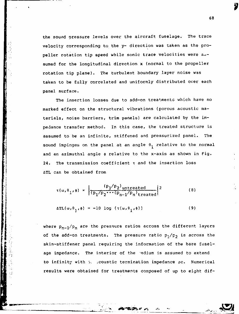
the sound pressure levels over the aircraft fuselage. The trace
velocity corresponding to the y- direction was taken as the pro-
peller rotation tip speed while sonic trace velocities were a,-
sumed for the longitudinal direction x (normal to the propeller
rotation tip plane). The turbulent boundary layer noise was
taken to be fully correlated and uniformly distributed over each
panel surf ace.
The insertion losses due to add-on treatments which have no
marked effect on the structural vibrations (porous acoustic ma-
terials, noise barriers, trim panels) are calculated by the im-
pedance transfer method. In this case, the treated structure is
assumed to be an infinite, stiffened and pressurized panel. The
sound impinges on the panel at an angle 8 relative to the normal 1
and an azimuth31 angle @ relative to the x-axis as shown in Fig.
24. The transmission coefficient T and the insertion loss
ATL can be obtained from
ATL(w,B, , @ ) = -1-0 log {T(U,~~,@)) ( 9 )
where ~,,~/p, are the pressure ratios across the different layers
of the add-on treatments. The pressure ratio p1/p2 is across the
skin-stiffener panel requiring the information of t.he bare fusel-
age impedance. The interior of the .odium is assumed to extend
to infinity with i. ,caustic termination impedance pc. Numerical
results were obtained for treatments composed of up to eight d i f -

L . . -
ferent layers and the elastic skin-stiffsner panel. These treat-
ments include porous acoustic materials, noise barriers and limp
trim panels.
Noise transmission measurements were obtained for the air-
craft shown in Fig. 39 for normal cruise at 214 kts, maximum con-
tinuous power 96 percent RPM, and altitude of 16,000 ft. This
aircraft has a maximum take-off weight of about 11,200 lbs, a
standard cabin layout for a pilot and seven passengers, pressur-
ized cabin environment and 35,000 ft operational ceiling. oper-
ating at 1500 RPM during cruise, the propeller blade passage fre-
quency is 75 Hz and the tip speed 692 ft/sec. The cabin height,
width and length are, respectively, 4.76 ft, 4 ft, and 17.5 ft.
Flight tests results are reported for twc acoustic treatment con-
figurations, Configuration 1 is referred as untreated which nad
no acoustic treatments and no carpet on the floor. However, four
seats (pilot, co-pilot and two passengers) were present for the
"untreated" and the *treatedn cases. Configuration 2 is similar
to the standard soundproofing treatment used in this aircraft.
This configuration includes a constrained layer damping tape
attached to th: aluminum skin, four layers of porous acoustic
blankets, two layers of lead vinyl septa, and a foam-rubber type
sandwich noise barrier. The combination of the treatments and
surface density varied kith location in the cabin. The heaviest
treatment of about 2.25 *b/ft2 was applied in the vicinity of the
propeller rotational plane. The hard-plastic trim panels were
not installed for these tests. However, the trim condition of a
"limp" pa: 21 was simulated by the presmce of the noise barrier
e -- --- -- .. . &
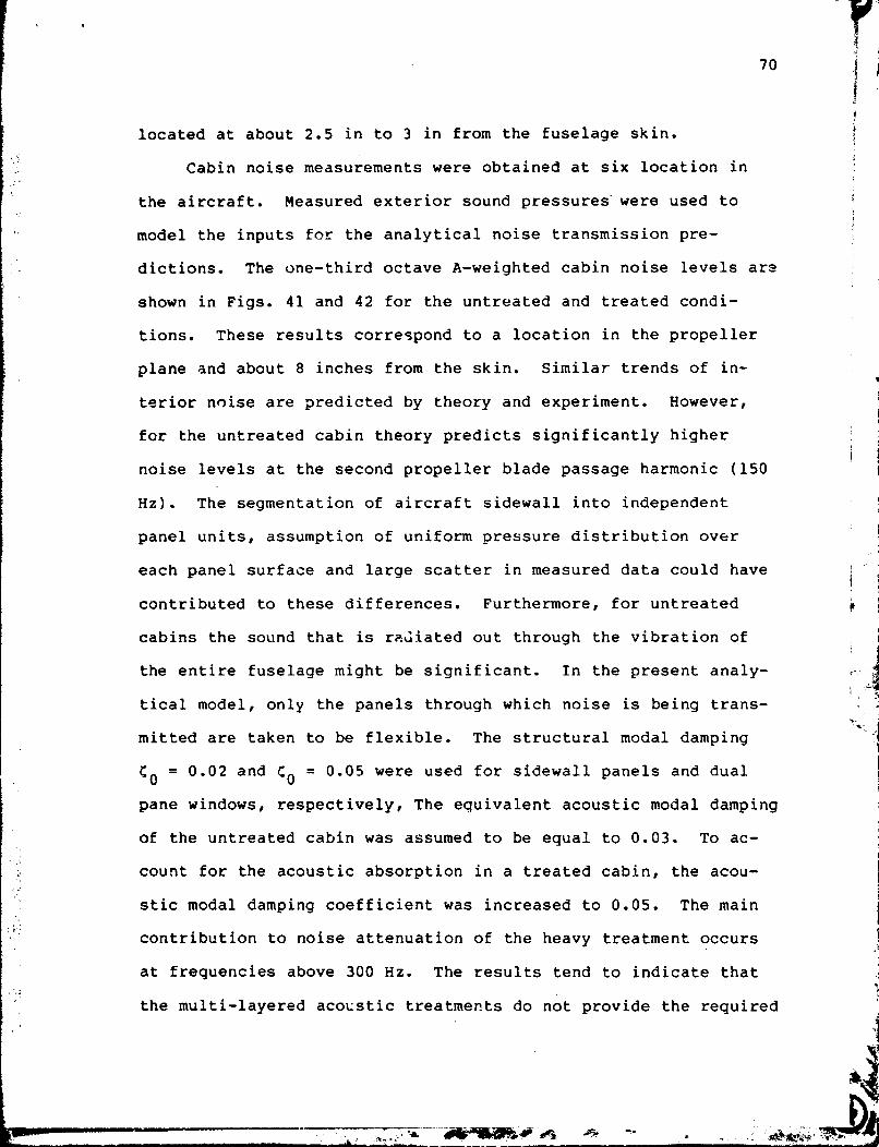
located at about 2.5 in to 3 in from the fuselage skin.
Cabin noise measurements were obtained at six location in
the aircraft. Measured exterior sound pressures'were used to
model the inputs for the analytical noise transmission pre-
dictions. The one-third octave A-weighted cabin noise levels arz
shown in Figs. 41 and 42 for the untreated and treated condi-
tions. These results correspond to a location in the propeller
plane and about 8 inches from the skin. Similar trends of in-
terior noise are predicted by theory and experiment. However,
for the untreated cabin theory predicts significantly higher
noise levels at the second propeller blade passage harmonic (150
Hz). The segmentation of aircraft sidewall into independent
panel units, assumption of uniform pressure distribution over
each panel surface and large scatter in measured data could have
contributed to these differences. Furthermore, for untreated
cabins the sound that is rzdiated out through the vibration of
the entire fuselage might be significant. In the present analy-
tical model, only the panels through which noise is being trans-
mitted are taken to be flexible. The structural modal damping
C o = 0.02 and to = 0.05 were used for sidewall panels and dual
pane windows, respectively, The equivalent acoustic modal damping
of the untreated cabin was assumed to be equal to 0.03. To ac-
count for the acoustic absorption in a treated cabin, the acou-
stic modal damping coefficient was increased to 0.05. The main
contribution to noise attenuation of the heavy treatment occurs
at frequencies above 300 Hz. The results tend to indicate that
the multi-layered acoustic treatments do not provide the required

noise attenuation for frequencies below 300 Hz where the propel-
ler inputs are the highest.
A theoretical parametric study h ~ s been carried out to eval-
uate a variety of candidate treatments for noise transmission
control in this aircraft under flight conditions. The following
add-on treatments were considered: honeycomb panels, constrained
layer damping tapes, non-load carrying mass, porous acoustic
blankets, noise barriers, trim panels and changes in window
design. The results from the 2arametric study were used to
design an acoustic treatnent suitable for noise control in this
airzraf t.
Fig. 39 Twin-engine aircraft used in noise transmission
study (dimensions in feet)

Propeller plane Y
,-Longerons
Acoustically rigid surfaces
Fig. 40 Aircraft sidewall model used for noise
transmission analysis
A Experiment
-50 1 63 125 250 500 1000
Frequency, Hz
Fig. 41 Normalized interior noise levels in an
untreated aircraft

A A Experiment
Frequency, Hz
Fig. 42 Normalized interior noise levels in the aircraft
treated with a heavy soundproofing package
5.4 New Proposed Acoustic Add-on Treatment
5 F The results of the parametric study were used to design a
treatment suitable to provide a more comfortable cabin noise I . . A
q level. The design objective was to reduce the overall interior . .
noise level of the untreated cabin by 17 dB cr better at standard -3- ,; 1
cruise power and rpm. To achieve this goal, substantial reduc-
tion of noise in the frequency bands of 160 Hz, 250 Hz and 315 Hz
(the propeller 2nd, 3rd and 4th harmonics) is needed. A treat-
ment whlch was found to meet these design objectives utilizes Lhe I
combination of honeycomb panels, constrained layer damping tape,
porous acousric materials, limp-isolated trim, tuned damping, and
modifications in window design. These add-on treatments, except
f; %
for windows, do not require structural. changes of the fuselage. I
1 i .*I
F
- .,- - - - ., .ha .. :% &- F* -- LI - - -- - --

e n t t r e a t m e n t s a n d w e i g h t c o n f i g u r a t i o n s t o d e s i g n t h e 0 2 t i m i z e d
t r e a t m e n t . F u r t h e r m o r e , t he . f u n c t i o n of t h i s t r e a t m e n t for n o i s e
c o n t r o l is b a s e d on t h e c o a d i t i o n t h a t n o i s e l e a k a g e t h r o u g h va-+
r i o u s f l a n k i n g p a t h s c a n be c o n t r o l l e d . I n s t a l l a t i o n of a bar- 4 rier be tween t h e c o c k p i t and t h e p a s s e n g e r c a b i n is l i k e l y t o be
needed t o r e d u c e n o i s e f l a n k i n g f rom t h e c o c k p i t r e g i o n . A
t r e a t e d a f t b u l k h e a d may a lso be needed t o r e d u c e n o i s e e n t e r i n g
f rom t h e rear o f t h e a i r c r a f t , and improve t h e i n t e r i o r a b s o r p -
t i o n i n t h e c a b i n .
The m u l t i l a y e r e d a c o u s t i c t r e a t m e n t f o r n o i s e c o n t r o l is de-
s i g n e d to f u n c t i o n as a u n i t r a t h e r t h a n s e p a r a t e i n d i v i d u a l com-
p o n e n t s . The honeycomb p a n e l s are a t t a c h e d t o t h e a i r c r a f t s k i n
a n d c c v e r t h e r e g i o n s bounded by f r a m e s and l o n g e r o n s . Aluminum
honeycomb p a n e l s w i t h a c o r e t h i c k n e s s o f 0 .25 i n . a n d t h e f a c e
p l a t e t h i c k n e s s e s 0.032 i n . ( r e g i o n o f p r o p e l l e r p l a n e ) and 0.016
i n . ( o t h e r w i s e ) are s e l e c t e d . A c o n s t r a i n e d l a y e r o f damping
t a p e is added t o a l l s k i n s u r f a c e s i n c l u d i n g t h e ceiling which i s
n o t treated w i t h honeycomb p a n e l s . A damping t a p e s u i t a b l e f o r
low t e m p e r a t u r e s s h o u l d be u s e d . T h r e e l a y e r s ( o n e i n c h t h i c k -
n e s s o f e a c h l a y e r ) o f p o r o u s a c o u s t i c materials are added t o a l l f !
a c c e s s i b l e s u r f a c e s o f t h e c a b i n . The f i r s t two l a y e r s a r e
t i g h t l y f i t t e d i n t h e r e g i o n s b e t w e e n ' s t i f f e n e r s w t ' l e t h e t h i r d
l a y e r c o v e r s e l l ' t h e f r a m e s and l o n g e r o n s . S p a c e p e r m i t t i n g , a
f o u r t h l a y e r s h o u l d be added t o f u r t h e r i n c r e a s e n o i s e r e d u c t i o n
and sound a b s o r p t i o n c a p a b i l i t y . I n order t o d e s i g n a p r a c t i c a l
a c o u s t i c t r e a t m e n t , a t r i m t h a t w i l l c o n t a i n t h e p o r o u s a c o u s t i c i

material and presents an acceptable appearance needs to be in-
stalled. The main function of the trim for noise control is to / . ' . , . .
-./ provide additional noise attenuation as the sound enters through a '. . the sidewall. A trim which has a low value of stiffness (limp I
panel concept) and is isolated from the vibration of the main
frame structure seems to be best suited for noise control in this ! T
! aircraft. Difficulties might arise installing the limp-trim
i panels in the aircraft. Lightweight honeycomb (paper, nontex,
etc.) or a layer of other acceptable materials can be attached to
the limp septa to increase the stiffness so that installation re- i
quirements are satisfied. The basic features qf the proposed
treatment are shown in Fig. 43. The effectiveness of the new
treatment for noise control has been evaluated experimentally i s
using Transmission Loss Apparatus facility described in Sec. I -
5.2.1. These results are shown in Fig. 44 where a direct com- ! - I parison of transmission loss for 695A (Acoustic treatment used
for production aircraft) and the new treatment is presented. As
can be observed from these results, the new treatment provided
about 5-10 dB additional noise attenuation in the critical fre- f" ,I
quency range of 100-500 Hz. However, the new treatment is light- !
er than the 695A treatment.
Experiments indicate that vibration of frames and longerons :I 1 i
are relatively large at the first two propeller blade passclge
harmonics. These vibrations are strongly coupled to the vibra-
tions of panels and windows. A tuned damper could provide reduc- 1 I1 tion of structural motions at a selected tuned frequency. Such a
3
reduction of structural response could subsequently lead to noise I 11

reduction at that frequency. Thus, it is recommended that vibra-
tion dampers tuned at the first and the second propeller blade
passage harmonics should be used to control the overall vibra-
tions of the fuselage.
The tests acd theoretical studies indicate that noise trans-
mitted through windows at the 2nd. 3rd and 4th propeller biade
passage harmonic could be a potential cause of high interior
noise levels in a treated aircraft. Thus, heavy sidewall treat-
ments night not solve the cabin noise problem if the windows are
providing a weak link in noise transmission. The window supports
of this aircraft are relatively flexible and the vibrations of
the windows are strongly coupled to the vibrations of the sup-
porting skin, longerons and frames. Thus, altering the window
design might not improve the noise transmission characteristics
if the bl~ndary support conditions are not changed. As the first
step to improve window design for noise transmission control, the
stiffness of the boundary supports should be increased signifi-
cantly. The theoretical parametric study suggests that one of
the alternatives to increase noise reduction for windows is to
increase the thickness of the exterior window pane. For the
present design of the proposed treatment, the thickness of the
exterior window pane should be increased to 0.5 in.
Figure 45 illustrates the treatment used in various cabin
regions. The surface densities and thicknesses of these add-on
treatments are given in Table 2. The total weight of this acou-
stic treatment is about 2% of the gross take-off weight of the
aircraft. The proposed treatment is slightly lighter than the

s t a n d a r d a c o u s t i c - t h e r m a l t r e a t m e n t used f o r t h i s a i r c r a f t . How-
e v e r , t h e new t r e a t m e n t s h o u l d p r o v i d e a b o u t 4-10 dB more o f
n o i s e r e d u c t i o n t h a n t h e s t a n d a r d t r e a t m e n t . L a b o r a t o r y tests
t e n d t o v e r i f y t h e s e p r e d i c t i o n s . A compar i son o f n o i s e t r a n s -
m i t t e d i n t o t h e u n t r e a t e d c a b i n (measured) and i n t o t h e c a b i n
w i t h t h e p roposed t r e a t m e n t ( c a l c u l a t e d ) is shown i n F ig . 46.
The a v e r a g e c a l c u l a t e d o v e r a l l n o i s e l e v e l s of t h e u n t r e a t e d ca-
b i n w i l l be r educed by a b o u t 17 dB w i t h t h e new a c o u s t i c ' r e a t -
ment.
f SIOEUALL STRUCTURE
,- HONEYCOMe
f 4 i n .
L I s o L A T I o N TRIM
Fig . 43 B a s i c f e a t u r e s of t h e p roposed new a c o u s t i c t r e a t m e n t

NEW: 2 psf i \ /
' / /
L Acoustic blankets
3'2 I I 1 1 I I I
63 125 250 500 1000 2000 4000 FREQUENCY IN CYCLES PER SECOND
Pig. 44 Transmission loss of a panel for two acoustic treatment
configurations
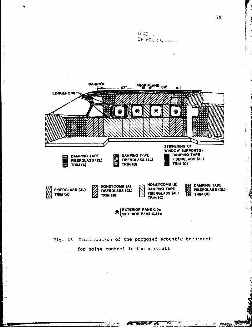
BARRIER PR
WINDOW SUPPORTS - DAMPING TAPE DAMPING T'bPE P DAMPING TAPE FIBERGLASS (2U FIBERGLASS (3U FIBERGLASS (3L) TRIM (A) TRIM (8) TRIM (C)
I HONEYCOMB (A) ffl HOFrEYCOMB (6) DAMPING TAPE
FIBERQLASS (3U FIBERGLASS (3L) DAMPING TAPE FIBERQLASS ( 3 0 TRIM (A) 'TRIM (8) FIBERGLASS (4U TRIM (6)
TRlM (C)
EXTERIOR PANE 0.5h INTERIOR PANE 0.25h
Fig. 45 Distribution of the proposed acoustic treatment
for noise control in the aircraft

SPL, dB A
lu atrnent (predicted) -30 , ,;
Frequency, Hz
F i g . 46 I n t e r i o r n o i s e l e v e l s of u n t r e a t e d and t r e a t e d
c a b i n s f o r f l i g h t c o n d i t i -ons .

-.
81
Table 1.
~escription of Add-on Treatments
7 .;4 Y + i I
r
-- .r.--,
-n
Yn
.--r*+
>..w
ry--
- . -
--
. a
- .,,
L
----
----
- - -
- . ,
-MiB
S,-.&
____ -
__ -
--_ _
- __
Treatment
Materials and Specifications
Surface De sity
lb/ft 9
Honeycomb Panels
Aluminum:
facing and core
0.60 -
0.66
Damping Tape
dense foam, adhesive and thin
0.296
aluminum foil
Acoustic Blankets
Fiberglass/Thermal
0.04 (one 0.75
in thick layer)
Acoustic Foam
Open cell foam with thin aluminum foil facing
0.125
(one 0.5
-
in thick layer)
--
--
Noise Barriers
101:
urethane elastomer bonded to decoupler
0.5
- 1.0
foam
103:
urethane elastomer bonded to acoustical
foam
104:
urethane elastomer bonded to decoupler
and acoustical foams
-. -
Vinyl Septa
Lead impregnated vinyl fabric
0.2
6
Trim
Stiff masonite panei, nois? barrier #101,
1.06,
1.0, 0.26
or lead vir.~ 1
- -a.

TABLE 2 S u r f a c e d e n s i t i e s and t h i c k n e s s e s
I T r i n ( C )
. TPqATMENT SURFACE
DENSITY LB / F T ~
Damping T a p 0.25
f i h e r g l a s s (2L) 0.16
F i b e r g l a s s ( 3L) 0.24
F i b e r g l a s s ( 4 L ) 0.32
Honeycomb ( A ) 0.40
Hcneycomb ( B ) 0.68
Trim ( A ) C.30
I Trim ( 8 ) 0.40
J
THICKNESS IN
0.25
1.80
2.70
3.60
0.27
0.28 .
0.13
0.13
o f add-on t r e a t m e n t s
I n c r e a s e i n Exterior Window Pane T h i c k n e s s 1.35 8:25
t

1. R e m ~ t NO. 2. Government Accacion NO. 3. Recipient's Catalog No. I
8. Performing Orlpnizat~on Repor: NO.
I I
Aircraf t Cabin Noise Prediction and Optimization
5. Report Date
v 19R5 6. Perfwrning Orgnization tOdr
12. Sponsorinp Agency Name and Address
R i m a s Vaica i t i s
9. Pkfaming Organization Nmt Md Ad&-
Colwbia University Department of Ci-:il Engineering and Engineering Mechanics
National Aeronclutics and Space Administration washington, D.C. 20546
10. Work Unit No.
11. Contract or Grant No.
NSG-1450 13. Type of R-n and Period Covered
14. Sponsoring Agency Code
I Langley technical monitor: D r . J.S. Mixson
I
16. Abstract I Theoretical and experimental s tud ies were conducted t o determine the noise I
I transmission i n t o acous t ic enclosures ranging from simple rectangular box models I I t o f u l l sca le l i g h t a i r c r a f t i n f l i gh t . The s t ruc tu ra l models include simple, I s t i f fened , curved s t i f fened , and orthotropic panels and double wall windows. The
) theore t ica l so lu t icns were obtained by modal ana lys is . Trlnsf9r matrix and f i n i t e I
I element procedures were u t i l i zed . Good agreement between theory and experiment I has been achieved. An e f f i c i e n t acoustic add-on treatment was developed f o r I - ? ,!i i n t e r i o r noise control i n a twin engine l i g h t a i r c r a f t .
17. Key Wwds (Suggest& by Authorls)) t Noisc Transmissio~,Acoustic Treatments Light Ai rcraf t I Unclassified - Unlimited Subject
l I .-
19. 9curity i ~ ~ i f . (of tl is report) 20. Security Classif. (c' this -1 I 27. NO. of P 1 ~ . r [ 22. Rice , .
\ Ul.classif ied 8 5 .:
I .
1 h- 35 For sale by the Nat~onal Techn~cal Ififormat~on Serv~ce. Sprlngf~eld. V ~ r g ~ n ~ a 22161