Report on Proposals F2006 — Copyright, NFPA NFPA … · Report on Proposals F2006 — Copyright,...
37
2001-1 Report on Proposals F2006 — Copyright, NFPA NFPA 2001 Report of the Committee on Gaseous Fire Extinguishing Systems Jeffrey L. Harrington, Chair Harrington Group, Incorporated, GA [SE] Ronald C. Adcock, Marsh USA Incorporated, AZ [I] Maurizio Barbuzzi, North American Fire Guardian Technology, Incorporated, Italy [M] Douglas J. Barylski, US Department of the Navy, DC [E] Todd A. Dillon, GE Insurance Solutions, OH [I] Philip J. DiNenno, Hughes Associates, Incorporated, MD [SE] William A. Eckholm, Firetrace International, AZ [M] Dale R. Edlbeck, Tyco Fire & Security/Ansul, WI [M] Don A. Enslow, BP Exploration (Alaska), AK [U] William A. Froh, US Department of Energy, DC [U] Matthew T. Gustafson, US Social Security Administration, MD [U] Howard S. Hammel, DuPont Fluoroproducts, DE [M] Robert H. Kelly, Fire Defense Equipment Company Incorporated, MI [IM] Rep. Fire Suppression Systems Association George E. Laverick, Underwriters Laboratories Incorporated, IL [RT] Norbert W. Makowka, National Association of Fire Equipment Distributors, IL [IM] Bella A. Maranion, US Environmental Protection Agency, DC [E] Robert C. Merritt, FM Global, MA [I] Robert G. Richard, Honeywell, Incorporated, NY [M] Paul E. Rivers, 3M Fire Protection, MN [M] Patrick W. Schoening, General Motors Corporation, MI [U] Joseph A. Senecal, Kidde-Fenwal, Incorporated, MA [M] Clifford R. Sinopoli, II, Exelon Corporation, PA [U] Rep. Edison Electric Institute Louise C. Speitel, US Federal Aviation Administration, NJ [E] Brad T. Stilwell, Fike Corporation, MO [M] Al Thornton, Chemtura, TX [M] Klaus Wahle, US Coast Guard, DC [E] () Fred K. Walker, US Department of the Air Force, FL [E] Robert T. Wickham, Wickham Associates, NH [SE] Rep. Halon Alternatives Research Corporation Thomas J. Wysocki, Guardian Services, Incorporated, IL [SE] Jiann C. Yang, US National Institute of Standards & Technology, MD [RT] Alternates Philip B. Atteberry, Chemtura, IL [M] (Alt. to Al Thornton) Kenneth V. Blanchard, DuPont Fluoroproducts, DE [M] (Alt. to Howard S. Hammel) Charles O. Bauroth, Liberty Mutual Property, MA [I] (Voting Alt. to PCIAA Rep.) Randall Eberly, US Coast Guard, DC [E] (Alt. to Klaus Wahle) Steven A. Giovagnoli, GE Insurance Solutions, IL [I] (Alt. to Todd A. Dillon) Raymond N. Hansen, US Department of the Air Force, FL [E] (Alt. to Fred K. Walker) William Matt Hogan, Duke Power Company, SC [U] (Alt. to Clifford R. Sinopoli, II) Daniel J. Hubert, Kidde/Chemetron Fire Systems, IL [M] (Alt. to Joseph A. Senecal) Mary P. Hunstad, US Department of the Navy, DC [E] (Alt. to Douglas J. Barylski) Giuliano Indovino, North American Fire Guardian Technology, Incorporated, Italy [M] (Alt. to Maurizio Barbuzzi) Robert Kasiski, FM Approvals/FM Global, RI [I] (Alt. to Robert C. Merritt) Richard A. Malady, Fire Fighter Sales & Service Company, PA [IM] (Alt. to Norbert W. Makowka) Earl D. Neargarth, Fike Corporation, MO [M] (Alt. to Brad T. Stilwell) Ivan M. Nibur, Global Risk Consultants Corporation, KY [SE] (Voting Alt. to GRC Corp. Rep.) Steven W. Rhodes, US Social Security Administration, MD [U] (Alt. to Matthew T. Gustafson) James M. Rucci, Harrington Group, Incorporated, GA [SE] (Alt. to Jeffrey L. Harrington) John M. Schuster, 3M Company, MN [M] (Alt. to Paul E. Rivers) Len D. Seebaluck, Firetrace International, AZ [M] (Alt. to William A. Eckholm) Margaret A. Sheppard, US Environmental Protection Agency, DC [E] (Alt. to Bella A. Maranion) John C. Spalding, Healey Fire Protection, Incorporated, MI [IM] (Alt. to Robert H. Kelly) George Unger, Underwriters’ Laboratories of Canada, Canada [RT] (Alt. to George E. Laverick) Nonvoting Rudolf Klitte, Ginge-Kerr Danmark A/S, Denmark [M] Ingeborg Schlosser, VdS Schadenverhutung, Germany [I] Fernando Vigara, Fernando Vigara & Asociados, Spain [SE] Staff Liaison: Mark T. Conroy Committee Scope: This Committee shall have primary responsibility for documents on the installation, maintenance, and use of carbon dioxide systems for fire protection. This Committee shall also have primary responsibility for documents on fixed fire extinguishing systems utilizing bromotrifluoromethane and other similar halogenated extinguishing agents, covering the installation, maintenance, and use of systems. This Committee shall also have primary responsibility for documents on alternative protection options to Halon 1301 and 1211 fire extinguishing systems. It shall not deal with design, installation, operation, testing, and maintenance of systems employing dry chemical, wet chemical, foam, aerosols, or water as the primary extinguishing media. This list represents the membership at the time the Committee was balloted on the text of this edition. Since that time, changes in the membership may have occurred. A key to classifications is found at the front of this book. The Technical Committee on Gaseous Fire Extinguishing Systems is presenting three Reports for adoption, as follows: Report I: The Committee proposes for adoption, amendments to NFPA 12, Standard on Carbon Dioxide Extinguishing Systems, 2000 edition. NFPA 12 is published in Volume 1 of the 2004/2005 National Fire Codes and in separate pamphlet form. NFPA 12 has been submitted to letter ballot of the Technical Committee on Gaseous Fire Extinguishing Systems, which consists of 32 voting members. The results of the balloting, after circulation of any negative votes, can be found in the report. Report II: The Technical Committee proposes for adoption, amendments to NFPA 12A, Standard on Halon 1301 Fire Extinguishing Systems, 2004 edition. NFPA 12A is published in Volume 1 of the 2004/2005 National Fire Codes and in separate pamphlet form. This Report has been submitted to letter ballot of the Technical Committee on Gaseous Fire Extinguishing Systems, which consists of 32 voting members; of whom 31voted affirmatively, and 1 ballot was not returned (T. Dillon). Report III: The Technical Committee proposes for adoption, amendments to NFPA 2001, Standard on Clean Agent Fire Extinguishing Systems, 2004 edition. NFPA 2001 is published in Volume 12 of the 2004/2005 National Fire Codes and in separate pamphlet form. This Report has been submitted to letter ballot of the Technical Committee on Gaseous Fire Extinguishing Systems, which consists of 32 voting members; of whom 27 voted affirmatively, 5 negatively after circulation of negative ballots (M. Barbuzzi, D. Edlbeck, H. Hammel, B. Stillwell, T. Wysocki). Mr. M. Barbuzzi voted negatively stating: Comment on 2001-1 (Log #5): The standard makes no reference to the commercial evaluation criteria with regards to applicability and acceptability. Mr. D. Edlbeck voted negatively stating: 2001-43 (Log #16): Testing done to UL test parameters does not indicate a substantial increase in extinguishing time of Class A fires when the discharge time is extended to 120 seconds. Detection and control systems used with Clean Agent systems are designed to suppress a fire in its incipient stage, long before it achieves a high burning rate that would allow increased damage caused by any longer extinguishing times associated with a 120 second discharge time. The USCG currently allows the 120 second discharge time for 85 percent of the design concentration as verified by the UL listing. The Marine chapter of this standard allows the 120 second discharge time based on the USCG listing. The benefits to the customer for the extended discharge outweigh any slight increase in extinguishing times.
Transcript of Report on Proposals F2006 — Copyright, NFPA NFPA … · Report on Proposals F2006 — Copyright,...

2001-1
Report on Proposals F2006 — Copyright, NFPA NFPA 2001 Report of the Committee on
Gaseous Fire Extinguishing Systems
Jeffrey L. Harrington, ChairHarrington Group, Incorporated, GA [SE]
Ronald C. Adcock, Marsh USA Incorporated, AZ [I]Maurizio Barbuzzi, North American Fire Guardian Technology, Incorporated, Italy [M]Douglas J. Barylski, US Department of the Navy, DC [E]Todd A. Dillon, GE Insurance Solutions, OH [I]Philip J. DiNenno, Hughes Associates, Incorporated, MD [SE]William A. Eckholm, Firetrace International, AZ [M]Dale R. Edlbeck, Tyco Fire & Security/Ansul, WI [M]Don A. Enslow, BP Exploration (Alaska), AK [U]William A. Froh, US Department of Energy, DC [U]Matthew T. Gustafson, US Social Security Administration, MD [U]Howard S. Hammel, DuPont Fluoroproducts, DE [M]Robert H. Kelly, Fire Defense Equipment Company Incorporated, MI [IM]
Rep. Fire Suppression Systems AssociationGeorge E. Laverick, Underwriters Laboratories Incorporated, IL [RT]Norbert W. Makowka, National Association of Fire Equipment Distributors, IL [IM]Bella A. Maranion, US Environmental Protection Agency, DC [E]Robert C. Merritt, FM Global, MA [I]Robert G. Richard, Honeywell, Incorporated, NY [M]Paul E. Rivers, 3M Fire Protection, MN [M]Patrick W. Schoening, General Motors Corporation, MI [U]Joseph A. Senecal, Kidde-Fenwal, Incorporated, MA [M]Clifford R. Sinopoli, II, Exelon Corporation, PA [U]
Rep. Edison Electric InstituteLouise C. Speitel, US Federal Aviation Administration, NJ [E]Brad T. Stilwell, Fike Corporation, MO [M]Al Thornton, Chemtura, TX [M]Klaus Wahle, US Coast Guard, DC [E] ()Fred K. Walker, US Department of the Air Force, FL [E]Robert T. Wickham, Wickham Associates, NH [SE] Rep. Halon Alternatives Research CorporationThomas J. Wysocki, Guardian Services, Incorporated, IL [SE]Jiann C. Yang, US National Institute of Standards & Technology, MD [RT]
AlternatesPhilip B. Atteberry, Chemtura, IL [M] (Alt. to Al Thornton)Kenneth V. Blanchard, DuPont Fluoroproducts, DE [M] (Alt. to Howard S. Hammel)Charles O. Bauroth, Liberty Mutual Property, MA [I] (Voting Alt. to PCIAA Rep.) Randall Eberly, US Coast Guard, DC [E] (Alt. to Klaus Wahle)Steven A. Giovagnoli, GE Insurance Solutions, IL [I] (Alt. to Todd A. Dillon)Raymond N. Hansen, US Department of the Air Force, FL [E] (Alt. to Fred K. Walker)William Matt Hogan, Duke Power Company, SC [U] (Alt. to Clifford R. Sinopoli, II)Daniel J. Hubert, Kidde/Chemetron Fire Systems, IL [M] (Alt. to Joseph A. Senecal)Mary P. Hunstad, US Department of the Navy, DC [E] (Alt. to Douglas J. Barylski)Giuliano Indovino, North American Fire Guardian Technology, Incorporated, Italy [M] (Alt. to Maurizio Barbuzzi)Robert Kasiski, FM Approvals/FM Global, RI [I] (Alt. to Robert C. Merritt)Richard A. Malady, Fire Fighter Sales & Service Company, PA [IM] (Alt. to Norbert W. Makowka)Earl D. Neargarth, Fike Corporation, MO [M] (Alt. to Brad T. Stilwell)Ivan M. Nibur, Global Risk Consultants Corporation, KY [SE] (Voting Alt. to GRC Corp. Rep.) Steven W. Rhodes, US Social Security Administration, MD [U] (Alt. to Matthew T. Gustafson)James M. Rucci, Harrington Group, Incorporated, GA [SE] (Alt. to Jeffrey L. Harrington)John M. Schuster, 3M Company, MN [M] (Alt. to Paul E. Rivers)Len D. Seebaluck, Firetrace International, AZ [M] (Alt. to William A. Eckholm)Margaret A. Sheppard, US Environmental Protection Agency, DC [E] (Alt. to Bella A. Maranion)John C. Spalding, Healey Fire Protection, Incorporated, MI [IM] (Alt. to Robert H. Kelly)
George Unger, Underwriters’ Laboratories of Canada, Canada [RT] (Alt. to George E. Laverick)
Nonvoting
Rudolf Klitte, Ginge-Kerr Danmark A/S, Denmark [M] Ingeborg Schlosser, VdS Schadenverhutung, Germany [I] Fernando Vigara, Fernando Vigara & Asociados, Spain [SE]
Staff Liaison: Mark T. Conroy
Committee Scope: This Committee shall have primary responsibility for documents on the installation, maintenance, and use of carbon dioxide systems for fire protection. This Committee shall also have primary responsibility for documents on fixed fire extinguishing systems utilizing bromotrifluoromethane and other similar halogenated extinguishing agents, covering the installation, maintenance, and use of systems.
This Committee shall also have primary responsibility for documents on alternative protection options to Halon 1301 and 1211 fire extinguishing systems. It shall not deal with design, installation, operation, testing, and maintenance of systems employing dry chemical, wet chemical, foam, aerosols, or water as the primary extinguishing media. This list represents the membership at the time the Committee was balloted on the text of this edition. Since that time, changes in the membership may have occurred. A key to classifications is found at the front of this book.
The Technical Committee on Gaseous Fire Extinguishing Systems is presenting three Reports for adoption, as follows:
Report I: The Committee proposes for adoption, amendments to NFPA 12, Standard on Carbon Dioxide Extinguishing Systems, 2000 edition. NFPA 12 is published in Volume 1 of the 2004/2005 National Fire Codes and in separate pamphlet form.
NFPA 12 has been submitted to letter ballot of the Technical Committee on Gaseous Fire Extinguishing Systems, which consists of 32 voting members. The results of the balloting, after circulation of any negative votes, can be found in the report.
Report II: The Technical Committee proposes for adoption, amendments to NFPA 12A, Standard on Halon 1301 Fire Extinguishing Systems, 2004 edition. NFPA 12A is published in Volume 1 of the 2004/2005 National Fire Codes and in separate pamphlet form.
This Report has been submitted to letter ballot of the Technical Committee on Gaseous Fire Extinguishing Systems, which consists of 32 voting members; of whom 31voted affirmatively, and 1 ballot was not returned (T. Dillon).
Report III: The Technical Committee proposes for adoption, amendments to NFPA 2001, Standard on Clean Agent Fire Extinguishing Systems, 2004 edition. NFPA 2001 is published in Volume 12 of the 2004/2005 National Fire Codes and in separate pamphlet form.
This Report has been submitted to letter ballot of the Technical Committee on Gaseous Fire Extinguishing Systems, which consists of 32 voting members; of whom 27 voted affirmatively, 5 negatively after circulation of negative ballots (M. Barbuzzi, D. Edlbeck, H. Hammel, B. Stillwell, T. Wysocki).
Mr. M. Barbuzzi voted negatively stating: Comment on 2001-1 (Log #5): The standard makes no reference to the
commercial evaluation criteria with regards to applicability and acceptability.
Mr. D. Edlbeck voted negatively stating: 2001-43 (Log #16): Testing done to UL test parameters does not indicate a
substantial increase in extinguishing time of Class A fires when the discharge time is extended to 120 seconds.
Detection and control systems used with Clean Agent systems are designed to suppress a fire in its incipient stage, long before it achieves a high burning rate that would allow increased damage caused by any longer extinguishing times associated with a 120 second discharge time.
The USCG currently allows the 120 second discharge time for 85 percent of the design concentration as verified by the UL listing. The Marine chapter of this standard allows the 120 second discharge time based on the USCG listing.
The benefits to the customer for the extended discharge outweigh any slight increase in extinguishing times.

2001-2
Report on Proposals F2006 — Copyright, NFPA NFPA 2001 Mr. H. Hammel voted negatively stating:
1. There are a number of Accepted or Accepted in Principle proposals that if incorporated into the standard will cause a significant change in system design and will impact currently installed systems. There are no data or substantiation to support these changes. To the contrary, there are years of installed systems that indicate the current accepted practice achieves the necessary margin of safety in the design of Clean Agent Systems.2. a) There is an effort to incorporate parts of an ISO standard that is still in the draft stage into NFPA 2001. This ISO standard utilizes Class A fire tests that are much larger than UL 2166/UL2127 and is based on visual interpretation only. There is very limited data for results from the ISO fire test. The reproducibility and consistency of this procedure is yet to be confirmed. In fact there was a wide difference in MEC data for the same agent depending if the system was super pressurized to 360 psig vs. 600 psig. UL standards have been used for many years. There is a proven margin of safety for systems based on the Class A fire test used in UL standards. b) Placing the Class A full-scale test data from the ISO method is not appropriate. Listing this data will only cause confusion. The hardware (especially nozzles) can effect the MEC and should be run for each hardware type, as is required by UL. If data is to place in NFPA 2001, it should be based on UL methodology.c) The current heptane cup burner data in NFPA is from the most current test method, current Annex B. It was determined form multiple tests from multiple sources. The ISO cup burner data is from one set of data from one source. Data derived from a different standard should not be included in NFPA 2001.
Mr. B. Stilwell voted negatively stating: 2001-1 (Log #18) – Disagree with Committee Action. 2001-37 (Log #11) and 2001-38 (Log #21) – Disagree with Committee Action.
Mr. T. Wysocki voted negatively stating: After consideration of comments accompanying negative ballots of Edlbeck, Stillwell, Hammel and Barbuzzi, I vote negative on this document for the following reasons: There is insufficient technical justification for the proposed changes to design concentration requirements. On the other hand, there is justification for extension of the discharge time for Class A fire suppression using inert gases and this extension was rejected. The proposed document is inconsistent in its handling of the various competing agents. There is nothing of extreme urgency requiring immediate change in NFPA 2001 that justifies going forward with an ROP which is replete with such inconsistent handling of competing agents.

2001-3
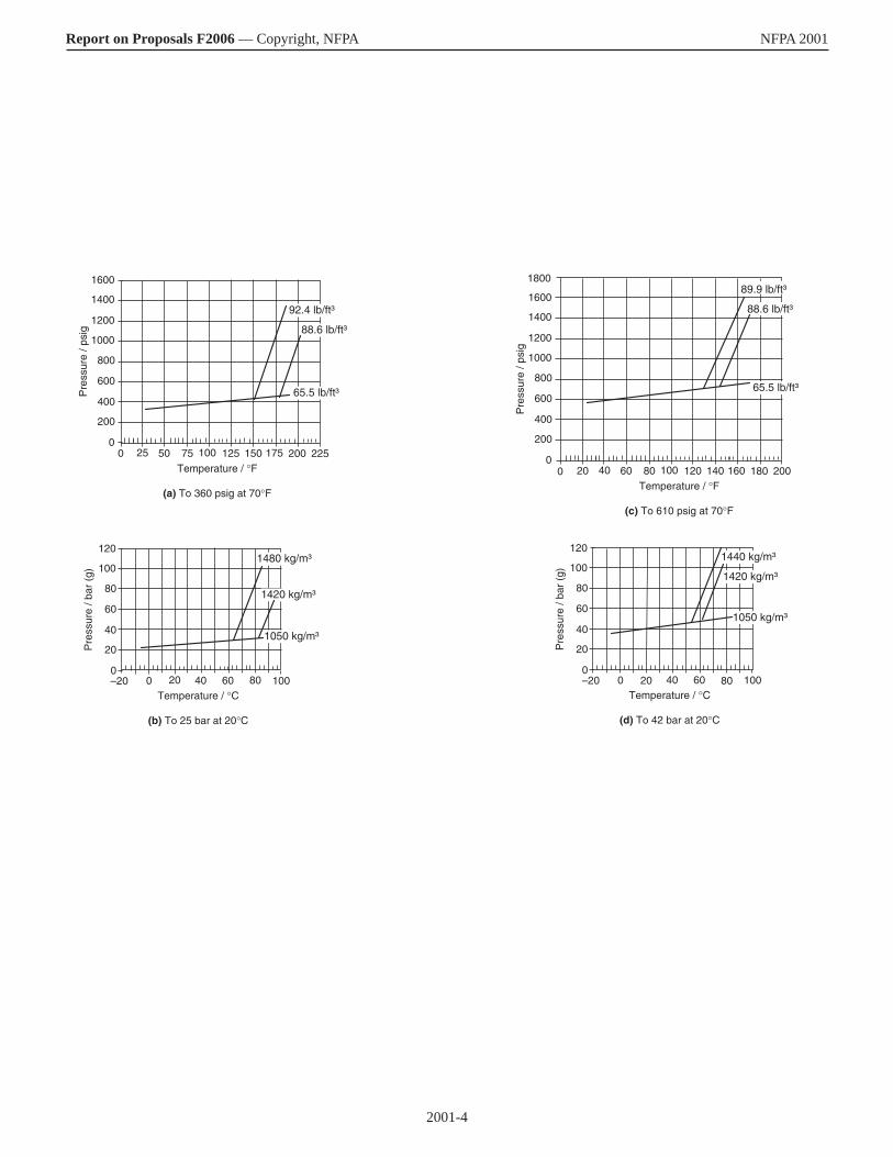
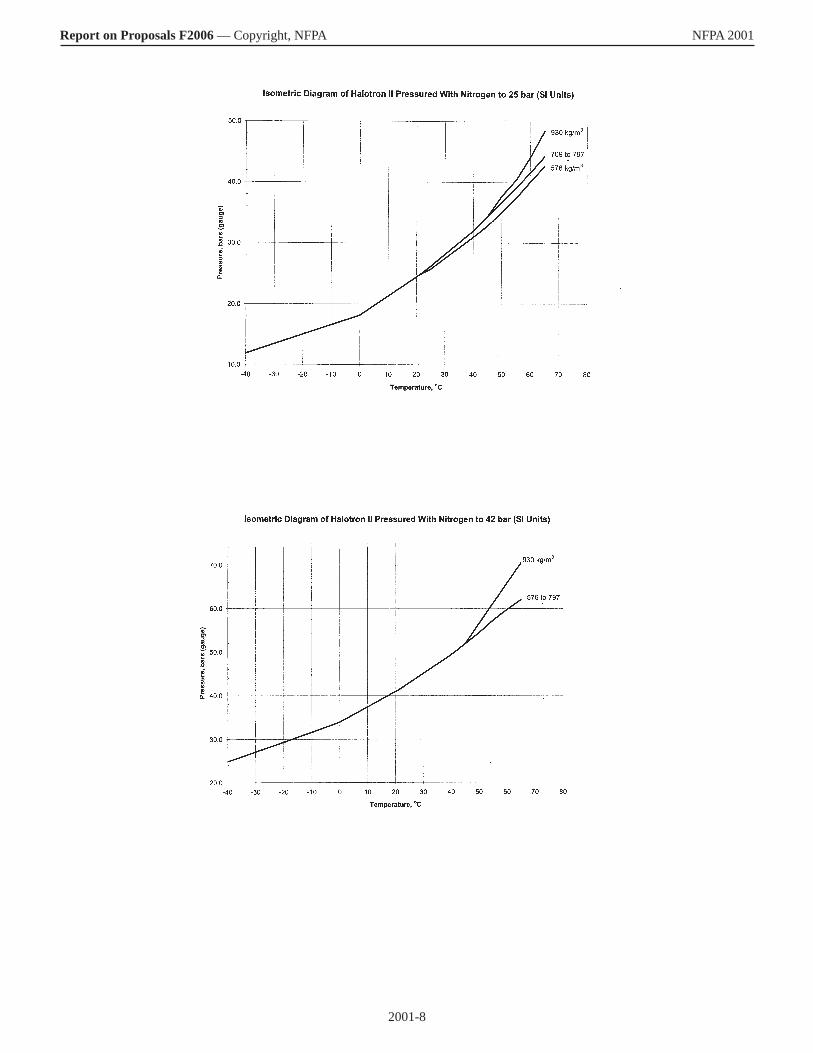
Report on Proposals F2006 — Copyright, NFPA NFPA 2001 ________________________________________________________________ 2001-1 Log #5 Final Action: Accept in Principle in Part (Entire Document) ________________________________________________________________ Submitter: Robert T. Wickham, Wickham Associates Recommendation: Delete all data for and references to the following three agents now covered in this standard: FC-3-1-10, HCFC Blend A and HCFC-124. Substantiation: Both FC-3-1-10 and HCFC-124 are being withdrawn from ISO 14520. FC-3-1-10, according to the manufacturer, is not being employed in new systems. Neither HCFC Blend A nor HCFC-124 have received commercial acceptance in engineered systems in the U.S. and both are subject to a production halt by 2020 mandated by the Clean Air Act. The inclusion of these three agents in this standard gives the false impression that there are more alternatives to halon available than is actually the case. The removal of these three agents will thus make the standard more useful by presenting to the user information on only those agents that are truly commercially viable. Committee Meeting Action: Accept in Principle in Part Delete all data for and references to the following two agents now covered in this standard: FC-3-1-10 and HCFC Blend A. Committee Statement: HCFC-124 is currently available in pre-engineered systems, therefore the committee did not delete data and references to that agent. ________________________________________________________________ 2001-2 Log #89 Final Action: Accept (1.1) ________________________________________________________________ Submitter: Bill Eckholm, Firetrace International Recommendation: Add a reference to local application systems in the first sentence 1-1 as follows: This standard contains minimum requirements for total flooding and local application clean agent fire systems. Substantiation: As addressed in the other submissions, it addresses the inclusion of local application systems in the standard. Committee Meeting Action: Accept ________________________________________________________________ 2001-3 Log #60 Final Action: Accept in Principle (Table 1.4.1.2) ________________________________________________________________ Submitter: Bradford Colton, American Pacific Corporation Recommendation: Revise Table 1.4.1.2 as follows: (first column) Halotron II (second column) tetrafluoromethane (86%), pentafluorethane (9%), carbon dioxide (5%) (third column) CH2, FCF3, CHF2, CF3, CO2 (Note: The EPA did not assign a generic name to this blend.) Substantiation: Halotron II is an EPA SNAP approved halon 1301 replacement for total flooding. The timing for this submittal is based on increased customer interest in wider use of this agent. Committee Meeting Action: Accept in Principle Revise Table 1.4.1.2 as follows: (first column) HFC Blend B (this will be updated later) (second column) tetrafluoroethane (86%), pentafluorethane (9%), carbon dioxide (5%) (third column) CH2, FCF3, CHF2, CF3, CO2 Committee Statement: Editorial changes. ________________________________________________________________ 2001-4 Log #87 Final Action: Accept (Figure 1.4.1.4.1(C)) ________________________________________________________________ Submitter: Paul E. Rivers, 3M Fire Protection Recommendation: 1. Revise graphs for 360 psig and 25 bar. 2. Add new graphs for 610 psig and 42 bar. See graphs on the next page Substantiation: 1. Graphs have been updated since the last edition. 2. High-pressure systems are now specified, designed and installed for which the added data are useful to the designer. Committee Meeting Action: Accept ________________________________________________________________ 2001-5 Log #64 Final Action: Accept in Principle (Table 1.4.1(a)) ________________________________________________________________ Submitter: Bradford Colton, American Pacific Corporation Recommendation: Revise Table A.1.4.1(a) as follows: Molecular weight: 99.4 Boiling point at 760 mm Hg: -26.1°C Freezing point: -103°C Critical temperature: 101.1°C Critical pressure: 4060 kPa Critical volume: 198 cc/mol Critical density: 515.3 kg/m3 Specific heat, liquid at 25°C: 1.44 kJ/kg°C Specific heat, vapor at 1 atm, 25°C: 0.848 kJ/kg°C
Heat of vaporization at boiling point: 217.2°C Thermal conductivity of liquid at 25°C: 0.082 W/m°C Viscosity, liquid at 25°C: 0.202 centipoise Relative dielectric strength at 1 atm, 734 mm Hg, 25°C: 1.014 Solubility of water in agent at 21°C: 0.11 %wt. Substantiation: Halotron II is an EPA SNAP approved halon 1301 replacement for total flooding. The timing for this submittal is based on increased customer interest in wider use of this agent. Committee Meeting Action: Accept in Principle Heat of vaporization at boiling point should be 217.2 kJ/kg (instead of 217.2 o C). Committee Statement: Editorially corrected the units. ________________________________________________________________ 2001-6 Log #97 Final Action: Reject (Table 1.4.2.1, 3.3.13 Inert Gas Agent, 4.1.3, 4.1.3.6, 4.1.4.7, 4.2.3.7, 5.1.2.3.2, 5.4.2.6, Annex A) ________________________________________________________________ Submitter: Denyse DuBrucq, AirWars Defense Recommendation: Add new text as follows: Table 1.4.2.1 - include N2 Nitrogen - Liquid Nitrogen 3.3.13 (add) These agents can be used in Liquid form. Agent 4.1.3 Quantity of LN for portable device, four liters volume is suggested. It required topping off twice a week. For fire department truck or trailer, one thousand gallons is suggested. This amount will produce Nitrogen gas sufficient to fill a three story home. For larger facilities, additional fire departments can bring their supplies and the supplier can send a truck for yet further needs. Not a drop will be left behind and all Nitrogen gas will dissipate into the atmosphere upon ventilating building. 4.1.3.6 Storage Container Arrangement for LN portable, 4-liter units can be kept inside buildings n locations appropriate for fire extinguishers with markings notifying user of cryogenic material and cold temperature precautions. The latched chain securing the dewar and sieve should be standard and use evident. Training in application and removal from holster is required with installation of the devices in a building, vehicle, public area, or industrial site. Fire Department Liquid Nitrogen tanks, dewars, are to be stored out of doors, but in a place where they can be driven or pulled without snow removal or deicing area. A lean-to type covering or removable fabric cover is suggested just off driveway or on parking lot. 4.1.4.7 Storage Container for LN. Liquid Nitrogen must be stored in a dewar built to contain cryogenic materials. Both 4-liter and 1,000 gallon supply must be thermos-type containers. 4.2.3.7 Fittings. The 4-liter dewar has a pull-off cap exposing a one inch (1 in.) diameter opening from which the Liquid Nitrogen is poured into the sieve when it is over the event to be drowned in Nitrogen and cooled in its evaporation. The 1,000 gallon tank has a valve opening with a quarter turn off to full on rotation. The hose has a two-inch (2 in.) diameter and is expected to flow full rate into the installed delivery equipment. The crisis facility may have fixed Liquid Nitrogen equipment installed so the Liquid Nitrogen is poured directly into that system. If not, the fire department will use its mobile equipment kit components to build the appropriate configuration for Liquid Nitrogen distribution. System Design 5.1.2.3.2 The portable Liquid Nitrogen device has a circular twelve-inch (12 in.) sieve unit with sides at least one inch (1 in.) high attached to the dewar so as to be horizontal and level. The Fixed Liquid Nitrogen system can be as simple as an outside wall mounted semicircular sieve unit at or above door height with a clear drop to the floor from that height giving the Liquid Nitrogen a good distance to fully evaporate before encountering the floor. For broad buildings, piping can carry Liquid Nitrogen to semicircular units in interior spaces. Tall buildings are plumbed to accept Liquid Nitrogen from helicopters or have a roof-level reservoir or higher if sharing availability among tall buildings. The mobile Liquid Nitrogen equipment kits contain 4 ft, 8 ft, and 12 ft straight troughs, some solid, some sieve bottomed with joints for long trough runs and elbows for encircling crisis. The joints and elbows have two sides, one solid, one sieve so one unit fits both modes in any angular configuration. Elbows come in 90° and 45° angles. Other kit contents include: the landmine legged “doughnut” shaped pan with hydraulic inserts in the legs that expand forming a basket around the landmine. With application of Liquid Nitrogen both the landmine and the hydraulic leg units freeze allowing the whole thing, ring, landmine, and legs to be lifted or shoveled into a shielded containment for bomb disposal. Piping with exhaust segments to build a structure in a flood circumstance on the source side of the flow, which will freeze the liquid in place making a dam covering a break or failure area of the material the original structure contains. A dyke holding back a water flow will have an ice dyke made with the tubes. While the pipe system is at cryogenic temperature, the dam will hold so the break can be repaired and, once it is cured or set and certified strong enough to hold, the Liquid Nitrogen application is stopped and the structure warms up melting the water. Then the pipe system is removed and dismantled until needed another time. Systematic checks for pipe condition is made after each such application to insure equipment reused will hold.
2001-4
Report on Proposals F2006 — Copyright, NFPA NFPA 2001
15012510075Temperature / °F
(a) To 360 psig at 70°F
500
600
400
200
0
800
Pre
ssur
e / p
sig
25 175 200 225
1400
1200
1000
1600
92.4 lb/ft³
88.6 lb/ft³
65.5 lb/ft³
6040Temperature / °C
(b) To 25 bar at 20°C
–20
60
40
20
0
80
Pre
ssur
e / b
ar (
g)
20 80 100
120
100
1050 kg/m³
1420 kg/m³
1480 kg/m³
0
14012010080Temperature / °F
(c) To 610 psig at 70°F
6020
600
400
200
0
800
Pre
ssur
e / p
sig
40 160 180 200
1400
1200
1000
1600
6040Temperature / °C
(d) To 42 bar at 20°C
–20
60
40
20
0
80
Pre
ssur
e / b
ar (
g)
20 80 100
120
1001420 kg/m³
1440 kg/m³
0
88.6 lb/ft³
65.5 lb/ft³
0
89.9 lb/ft³
1050 kg/m³
1800
2001-5
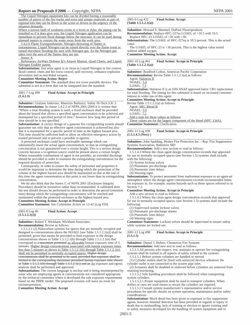
Report on Proposals F2006 — Copyright, NFPA NFPA 2001 The Liquid Nitrogen equipment kits can be divided having a reasonable number of pieces of the fire trucks and extra and unique materials as part of regional kits that can be flown to the scene or driven as the urgency of the situation demands. Where a known fault of weakness exists in a levee or dyke, the piping can be installed so if it does give way, the Liquid Nitrogen application can be immediate to prevent flood damage below the structure. It can be used during planned repairs to contain the water away from the work area. 5.4.2.6 Flame Extinguishments. Nitrogen drowning of flames is instantaneous. Liquid Nitrogen can be rained directly over the flame event or rained elsewhere flooding the area with Nitrogen gas. As the Nitrogen gas takes over the area of the flames they are out. Annex A References: AirWars Defense lp’s Airport Manual. Quad Charts, and Liquid Nitrogen Enabler patent. Substantiation: Just what agent is as clean as Liquid Nitrogen in fire control, flood control, chem and bio toxin control, spill recovery, ordnance explosion prevention and as non-lethal weapon. Committee Meeting Action: Reject Committee Statement: The standard does not cover portable devices. The submittal is not in a form that can be integrated into the standard. ________________________________________________________________ 2001-7 Log #99 Final Action: Accept in Principle (1.4.2.3) ________________________________________________________________ Submitter: Giuliano Indovino, Maurizio Barbuzzi, Safety Hi-Tech S.R. L. Recommendation: In clause 1.4.2.3 of NFPA 2001-2004 it is written that: “Where a total flooding system is used, a fixed enclosure shall be provided about the hazard that allows a specified agent concentration to be achieved and maintained for a specified period of time,” however how long this period of time should be is not specified. Substantiation: A correct design of a gaseous fire extinguishing system should guarantee not only that an effective agent concentration is achieved but also that it is maintained for a specific period of time at the highest hazard area. This time should be sufficient both to allow an effective emergency action by trained personnel and to prevent a possible re-igniton. A protected enclosure could have unclosable openings which can substantially lower the actual agent concentration, so that an extinguishing concentration is not guaranteed over a certain height. This is a serious design concern because a re-ignition source could be present above a certain height. Where reasonable confinement of agent is not possible, an extended discharge should be provided in order to maintain the extinguishing concentration for the required duration of protection. Consequently, in order to ensure the safety of personnel and properties it would be important to determine the time during which the protection of the volume at the highest hazard area should be maintained so that at the end of this time the agent concentration at this point is not lower than its extinguishing concentration. We do also think that the Annex C of NFPA 2001 (Enclosure Integrity Procedure) should be normative rather than recommended. A calibrated door fan test should always be performed in order to determine the period (retention time) during which the extinguishing concentration will be reached and maintained within the protected enclosure at the highest hazard area. Committee Meeting Action: Accept in Principle Committee Statement: See Committee Action on 12-42 (Log #20) ________________________________________________________________ 2001-8 Log #6 Final Action: Accept (1.5.1.2.1(2)) ________________________________________________________________ Submitter: Robert T. Wickham, Wickham Associates Recommendation: Revise as follows: 1.5.1.2.1 (2) Halocarbon systems for spaces that are normally occupied and designed to concentrations above the NOAEL [see Table 1.5.1.2.1(a)] shall be permitted, given that means be provided to limit exposure to the design concentrations shown in Table 1.5.1.2.1(b) through Table 1.5.1.2.1(e) that correspond to a maximum permitted an allowable human exposure time of 5 minutes. Higher design concentrations associated with human exposure times less than 5 minutes as shown in Table 1.5.1.2.1(b) through Table 1.5.1.2.1(e) shall not be permitted in normally occupied spaces. Higher design concentrations shall be permitted to be used, provided that exposure shall be limited to the corresponding maximum permitted human exposure time shown in Table 1.5.1.2.1(b) through Table 1.5.1.2.1(c) and an An exposure and egress analysis shall be performed and approved. Substantiation: The current language is unclear and is being misinterpreted by some who are employing agents at concentrations not considered appropriate by the technical committee where it developed the safe exposure requirements based on the PBPK model. The proposed revision will leave no room for misinterpretation. Committee Meeting Action: Accept
________________________________________________________________ 2001-9 Log #22 Final Action: Accept (Table 1.5.1.2.1(a)) ________________________________________________________________ Submitter: Howard S. Hammel, DuPont Fluoroproducts Recommendation: Replace HFC-227ea LOAEL of >10.5 with 10.5. Replace HFC-23 LOAEL of >50 with >30. Substantiation: The LOAEL of HFC-227ea is 10.5 percent. This is the actual value. The LOAEL of HFC-23 is >30 percent. This is the highest value tested without added oxygen. Committee Meeting Action: Accept ________________________________________________________________ 2001-10 Log #61 Final Action: Accept in Principle (Table 1.5.1.2.1(a)) ________________________________________________________________ Submitter: Bradford Colton, American Pacific Corporation Recommendation: Revise Table 1.5.1.2.1(a) as follows: Agent: Halotron II NOAEL: 5.0 LOAEL: 7.5 Substantiation: Halotron II is an EPA SNAP approved halon 1301 replacement for total flooding. The timing for this submittal is based on increased customer interest in wider use of this agent. Committee Meeting Action: Accept in Principle Revise Table 1.5.1.2.1(a) as follows: Agent: HFC Blend B NOAEL: 5.0 LOAEL: 7.5 Add a note for these values as follows: These values are for the largest component of the blend (HFC 134A). Committee Statement: Clarification. ________________________________________________________________ 2001-11 Log #38 Final Action: Accept in Principle (1.5.1.4.3 (New) ) ________________________________________________________________ Submitter: John Spalding, Healey Fire Protection Inc. / Rep. Fire Suppression Systems Association, Baltimore MD Recommendation: Add a new section to read as follows: 1.5.1.4.3 Where the clean agent design concentration exceeds that approved for use in normally occupied spaces (see Section 1.5) systems shall include with the following: (1) System lockout valves (2) Pneumatic pre-discharge alarms (3) Pneumatic time delays (4) Warning signs Substantiation: To protect personnel from inadvertent exposure to an agent-air atmosphere where the design agent concentration exceeds recommended limits for exposure in, for example, marine hazards such as those spaces referred to in Section 7.3. Committee Meeting Action: Accept in Principle Add a new section to read as follows: 1.5.1.4.3 Where the clean agent design concentration exceeds that approved for use in normally occupied spaces, (see Section 1.5) systems shall include the following: (1) Supervised system lockout valves (2) Pneumatic pre-discharge alarms (3) Pneumatic time delays (4) Warning signs Committee Statement: Lockout valves should be supervised to ensure safety while systems are locked out. ________________________________________________________________ 2001-12 Log #98 Final Action: Accept in Principle (1.5.1.5) ________________________________________________________________ Submitter: Daniel J. Hubert, Chemetron Fire Systems Recommendation: Add new text to read as follows: 1.5.1.5 All persons who inspect, test, maintain or operate fire extinguishing systems shall be trained in all aspects of safety related to the systems. 1.5.1.5.1 Before system cylinders are handled or moved: (1) Cylinder outlets shall be fitted with antirecoil devices whenever the cylinder outlet is not connected to the system pipe inlet. (2) Actuators shall be disabled or removed before cylinders are removed from retaining bracketing. 1.5.1.5.2 Safe handling procedures shall be followed when transporting system cylinders. 1.5.1.5.2.1 Proper equipment shall be used to transport cylinders. When dollies or carts are used means to secure the cylinders are required. 1.5.1.5.2 Consult system manufacturer’s representative and/or service procedures for specific details on system operation, maintenance and/or safety considerations. Substantiation: Much detail has been given to exposure to fire suppression agents, however minimal direction has been provided in regards to injury or death due to mishandling, lack of training or election to ignore training and/or safety measures developed for the handling of system equipment and or

2001-6
Report on Proposals F2006 — Copyright, NFPA NFPA 2001 components. Committee Meeting Action: Accept in Principle Add new text to read as follows: 1.5.1.5 All persons who inspect, test, maintain or operate fire extinguishing systems shall be trained in all aspects of safety related to the systems. 1.5.1.5.1 Before system cylinders are handled or moved: (1) Cylinder outlets shall be fitted with antirecoil devices, cylinder caps, or both whenever the cylinder outlet is not connected to the system pipe inlet. (2) Actuators shall be disabled or removed before cylinders are removed from retaining bracketing. 1.5.1.5.2 Safe handling procedures shall be followed when transporting system cylinders. 1.5.1.5.2.1 Equipment designed for transporting cylinders shall be used. When dollies or carts are used, cylinders shall be secured. 1.5.1.5.2 System manufacturer’s service procedures shall be followed for specific details on system operation, maintenance, and safety considerations. Committee Statement: Added criteria for safe handling of cylinders. ________________________________________________________________ 2001-13 Log #CP1 Final Action: Accept (Chapter 3 Definitions (GOT)) ________________________________________________________________ Submitter: Technical Committee on Gaseous Fire Extinguishing Systems Recommendation: Adopt the preferred definitions from the NFPA Glossary of Terms for the following terms: Class A Fire. (preferred) NFPA 10, 2002 ed A fire in ordinary combustible materials, such as wood, cloth, paper, rubber, and many plastics. Class A Fires. (secondary) NFPA 2001, 2004 ed. Fires in ordinary combustible materials, such as wood, cloth, paper, rubber, and many plastics. Class B Fire. (preferred) NFPA 10, 2002 ed. A fire in flammable liquids, combustible liquids, petroleum greases, tars, oils, oil-based paints, solvents, lacquers, alcohols, and flammable gases. Class B Fires. (secondary) NFPA 2001, 2004 ed. Fires in flammable liquids, combustible liquids, petroleum greases, tars, oils, oil-based paints, solvents, lacquers, alcohols, and flammable gases. Class C Fire. (preferred) NFPA 10, 2002 ed. A fire that involves energized electrical equipment. Class C Fires. (secondary) NFPA 2001, 2004 ed. Fires that involve energized electrical equipment where the electrical nonconductivity of the extinguishing media is of importance. Substantiation: Adoption of preferred definitions will assist the user by providing consistent meaning of defined terms throughout the National Fire Codes. Committee Meeting Action: Accept ________________________________________________________________ 2001-14 Log #39 Final Action: Accept (3.3.x Lockout Valve (New) ) ________________________________________________________________ Submitter: John Spalding, Healey Fire Protection Inc. / Rep. Fire Suppression Systems Association, Baltimore MD Recommendation: Add a new definition to read as follows: Lockout Valve. A manually operated valve in the discharge pipe between the nozzles and the agent supply, which can be locked in the closed position to
prevent flow of agent to the protected area. Substantiation: The new definition compliments the new requirement that a lockout valve be used as described in the proposed new 1.5.1.4.3. Committee Meeting Action: Accept ________________________________________________________________ 2001-15 Log #91 Final Action: Accept in Principle (3.3.14 Local Application) ________________________________________________________________ Submitter: Bill Eckholm, Firetrace International Recommendation: Add a new definition as follows: 3.3.14 Local Application: The act and manner of discharging an agent for the purpose of achieving a specified minimum agent concentration in proximity to the specified fire hazard, but not necessarily throughout the hazards total volume. Renumber remaining sections. Substantiation: Local applications were not included in the original NFPA 2001 document as no systems were listed or approved for local application with clean agents addressed by this document. This has changed. Therefore, the standard needs to incorporate the definition of Local Application. Committee Meeting Action: Accept in Principle Add the following definition: Local application system. A system consisting of a supply of extinguishing agent arranged to discharge directly on the burning material. Committee Statement: This definition was lifted from NFPA 12. ________________________________________________________________ 2001-16 Log #56 Final Action: Accept in Principle (Figure 4.1.4.1(n), and Table 4.1.4.1) ________________________________________________________________ Submitter: Bradford Colton, American Pacific Corporation Recommendation: Add the Halotron II total flooding agent into this standard. Table A.1.4.1: Max fill density: 58 lb/ft3 Minimum container working pressure: 400 psig Pressure at 70°F: 195 psig (vapor pressure of agent) Add new Figure A.4.1.4.1(n). See Figures on the following pages Substantiation: Halotron II is an EPA SNAP approved halon 1301 replacement for total flooding. The timing for this submittal is based on increased customer interest in wider use of this agent. Committee Meeting Action: Accept in Principle Change name from Halotron II to HFC Blend B. Committee Statement: Editorial. ________________________________________________________________ 2001-17 Log #36 Final Action: Accept (Table 4.2.1.1(b)) ________________________________________________________________ Submitter: David Rausch, Kidde-Fenwal, Inc. Recommendation: Add new system pressure data as shown in the following table:
Table 4.2.1.1(b) Minimum Design Working Pressure for Halocarbon Clean Agent System Piping
Agent Agent Container
Maximum Fill Density (lb/ft3)
Agent Container Charging Pressure
at 70°F (21°C) (psig)
Agent Container Pressure at 130°F
(55°C) (psig)
Minimum Piping Design Pressure at 70°F (21°C) (psig)
HFC-227ea 79 44*1 135 41675 150 249 20072 360 520 41672 600 1025 820
FC-3-1-10 80 360 450 360HCFC Blend A
56.2 600 850 680
56.2 360 540 432HFC 23 48 608.9* 1713 1371
45 608.9* 1560 124840 608.9* 1382 110635 608.9* 1258 100730 608.9* 1158 927
HCFC-124 74 240 354 283HCFC-124 74 360 580 464HFC-125 54 360 615 492HFC-125 56 600 1045 836HFC-236fa 74 240 360 280HFC-236fa 75 360 600 480HFC-238fa 74 600 1100 880FK-5-1-12 90 360* 413 360*Not superpressurized with nitrogen. 1Nitrogen delivered to agent cylinder through a flow restrictor upon system actuation. Nitrogen supply cylinder pres-sure is 1800 psig at 70°F (21°C).

2001-7
Report on Proposals F2006 — Copyright, NFPA NFPA 2001
2001-8
Report on Proposals F2006 — Copyright, NFPA NFPA 2001

2001-9
Report on Proposals F2006 — Copyright, NFPA NFPA 2001 Substantiation: The proposed addition to Table 4.3.1.1(b) supplies technical data that is presently absent for a commercially available HFC-227ea fire extinguishing system. Committee Meeting Action: Accept ________________________________________________________________ 2001-18 Log #63 Final Action: Accept in Principle (Table 4.2.1.1(b)) ________________________________________________________________ Submitter: Bradford Colton, American Pacific Corporation Recommendation: Revise Table 4.2.1.1(b) as follows: Agent: Halotron II Max Fill Density: 58 lb/ft3 Agent Charging Pressure: 360 psig Container Pressure at 130°F: 586 psig Minimum Piping Design Pressure: 469 psig Agent: Halotron II Max Fill Density: 58 lb/ft3 Agent Charging Pressure: 600 psig Container Pressure at 130°F: 888 psig Minimum Piping Design Pressure: 710 psig Substantiation: Halotron II is an EPA SNAP approved halon 1301 replacement for total flooding. The timing for this submittal is based on increased customer interest in wider use of this agent. Committee Meeting Action: Accept in Principle Change name from Halotron II to HFC Blend B. Committee Statement: Editorial. ________________________________________________________________ 2001-19 Log #88 Final Action: Accept (Table 4.2.1.1(b)) ________________________________________________________________ Submitter: Paul E. Rivers, 3M Fire Protection Recommendation: 1. Delete the asterisk next to the 360 psig reference for FK-5-1-12. 2. Add pertinent data for FK-5-1-12 that applies to a system superpressurized to 610 psig.
Substantiation: 1. Editorial correction. 2. High-pressure systems are now specified, designed and installed for which the added data are useful to the designer. Committee Meeting Action: Accept ________________________________________________________________ 2001-20 Log #17 Final Action: Accept in Principle (4.2.4.3 and 4.2.4.4 (New) ) ________________________________________________________________ Submitter: David Rausch, Kidde-Fenwal, Inc. Recommendation: Add new text to read as follows: 4.2.4.3 Where directional valves are used for multi-hazard protection, the directional valves shall be listed or approved for use with the installed suppression system. 4.2.4.4 Where directional valves are used for multi-hazard protection, the control equipment shall be specifically listed for the number, type and operation of those valves. Substantiation: There is no current text in NFPA 2001 to specifically address multi-hazard, directional valve, system protection and the completeness (i.e., Suppression system, Operation of and Control system) needed of these systems. Committee Meeting Action: Accept in Principle
Add new text to read as follows: 4.2.4.4 Where directional valves are used for multi-hazard protection, the directional valves shall be listed or approved for use with the installed suppression system. 4.3.4.1.1 Where directional valves are used for multi-hazard protection, the control equipment shall be listed or approved for the number, type and operation of those valves. Committee Statement: Adding “or approved” allows the AHJ to decide on installations in addition to the listing. ________________________________________________________________ 2001-21 Log #40 Final Action: Accept in Principle (4.3.3.5.1, A.4.3.3.5.1 (New) ) ________________________________________________________________ Submitter: John Spalding, Healey Fire Protection Inc. / Rep. Fire Suppression Systems Association, Baltimore MD Recommendation: Add the following new sections: 4.3.3.5.1* A discharge pressure switch shall be required where mechanical system actuation is possible. Add the following new annex material: A.4.3.3.5.1 A discharge pressure switch can serve to initiate electrical functions that normally occur upon system actuation such as shutdown functions and control panel actuation. Substantiation: A discharge pressure switch provides a suitable means to initiate electrical functions that normally occur upon system actuation by automatic or manual electric actuation. Committee Meeting Action: Accept in Principle Add the following new sections: 4.3.3.5.1* A discharge pressure switch shall be required where mechanical system actuation is possible. 4.3.3.5.2 The discharge pressure switch shall provide an alarm initiating signal to the releasing panel. Add the following new annex material: A.4.3.3.5.1 A discharge pressure switch can serve to initiate electrical functions that normally occur upon system actuation such as shutdown functions and control panel actuation. Committee Statement: Correlated this requirement with NFPA 12.
________________________________________________________________ 2001-22 Log #41 Final Action: Accept (4.3.5.5.1 (New) ) ________________________________________________________________ Submitter: John Spalding, Healey Fire Protection Inc. / Rep. Fire Suppression Systems Association, Baltimore MD Recommendation: Add a new section to read as follows: 4.3.5.5.1 Warning and safety instruction signs shall be located such that they will be readily visible to personnel in the area where the clean agent design concentration exceeds that approved for use in normally occupied spaces. The safety sign format, color, letter style of the signal words shall be in accordance with ANSI Z535. Substantiation: Life safety aspects of clean agent systems used at agent design concentrations exceeding those approved for use in normally occupied spaces will be enhanced by adoption of the generally recognized practice for the use of safety signs as given in ANSI Z535. Committee Meeting Action: Accept ________________________________________________________________ 2001-23 Log #42 Final Action: Accept in Principle (4.3.5.5.2 (New) ) ________________________________________________________________ Submitter: John Spalding, Healey Fire Protection Inc. / Rep. Fire Suppression
Table 4.2.1.1(b) Minimum Design Working Pressure for Halocarbon Clean Agent System Piping
Agent Agent Container
Maximum FillDensity (lb/ft3)
Agent ContainerCharging Pressure at
70°F (21°C)(psig)
Agent ContainerPressure at 130°F
(55°C)(psig)
Minimum Piping Design Pressure at
70°F (21°C)(psig)
FC-3-1-10 80 360 450 360FK-5-1-12 90 360* 413 360FK-5-1-12 90 610 700 610HCFC-124 74 240 354 283HCFC-124 74 360 580 464HCFC Blend A 56.2 600 850 680
HCFC Blend A 56.2 360 540 432HFC-125 54 360 615 492HFC-125 56 600 1045 836HFC-227ea 62 150 247 198HFC-227ea 72 360 520 416HFC-227ea 72 600 1025 820HFC 23 54 608.9* 2182 1746HFC 23 49 608.9* 1765 1412HFC-236fa 74 240 360 280HFC-236fa 75 360 600 480HFC-236fa 74 600 1100 880* Not superpressurized with nitrogen.
2001-10
Report on Proposals F2006 — Copyright, NFPA NFPA 2001 Systems Association, Baltimore MD Recommendation: Add a new section to read as follows: 4.3.5.5.2 Warning and safety instruction signs shall be located outside each entrance to clean agent cylinder storage rooms. The safety sign format, color, letter style of the signal words shall be in accordance with ANSI Z535, Standard for Environmental and Facility Safety Signs. Substantiation: Clean agent concentrations higher than approved for normally occupied spaces can occur in these areas. Life safety of personnel will be enhanced by adoption of the generally recognized practice for the use of safety signs as given in ANSI Z535. Committee Meeting Action: Accept in Principle Committee Statement: Corrected the ANSI reference.
________________________________________________________________ 2001-24 Log #43 Final Action: Reject (4.3.5.6.1) ________________________________________________________________ Submitter: John Spalding, Healey Fire Protection Inc. / Rep. Fire Suppression Systems Association, Baltimore MD Recommendation: Delete the last sentence of 4.3.5.6.1. Substantiation: Elimination of the requirement that a time delay be employed in the case of fast growth fire risk does not promote personnel safety. Time delays are required in marine systems where fast growth fire hazards are the norm; representatives of marine systems have not indicated that this is a problem. Committee Meeting Action: Reject Committee Statement: The statement does not require that time delays be eliminated, only that they be permitted to be eliminated. ________________________________________________________________ 2001-25 Log #44 Final Action: Accept (4.3.6) ________________________________________________________________ Submitter: John Spalding, Healey Fire Protection Inc. / Rep. Fire Suppression Systems Association, Baltimore MD Recommendation: Revise text to read as follows: 4.3.6* Unwanted System Operation. To avoid unwanted discharge of a clean agent system, a supervised disconnect switch shall be provided. The disconnect switch , when operated, shall interrupt the releasing circuit to the suppression system. Substantiation: Clarifies the fact that the disconnect switch only interrupts the releasing circuit to the suppression system when the disconnect switch is “operated.” Committee Meeting Action: Accept ________________________________________________________________ 2001-26 Log #92 Final Action: Accept (5.1.1) ________________________________________________________________ Submitter: Bill Eckholm, Firetrace International Recommendation: Add a reference to local application systems in the first sentence of 5.1.1 as follows: Specifications for total flooding and local application clean agent fire systems...” Substantiation: Recognizes that the same comments apply to local application systems, as apply to total flooding systems. Committee Meeting Action: Accept ________________________________________________________________ 2001-27 Log #29 Final Action: Accept (5.1.2.2(10) (New) ) ________________________________________________________________ Submitter: Jeffrey L. Harrington, Harrington Group, Inc. Recommendation: Add the following as a new 5.1.2.2, item 10 and renumber accordingly: 5.1.2.2(10) For an enclosure protected by a clean agent fire extinguishing system an estimate of the maximum positive and the maximum negative pressure, relative to ambient pressure, expected to be developed upon the discharge of agent shall be made. (see section 5.3.7) Substantiation: The failure of an enclosure due to discharge pressures that exceed the ability of the enclosure to remain intact presents a safety concern for people in or near the protected space. Steps must be taken to assure safety. Committee Meeting Action: Accept ________________________________________________________________ 2001-28 Log #62 Final Action: Accept in Principle (Table 5.1.2(d)) ________________________________________________________________ Submitter: Bradford Colton, American Pacific Corporation Recommendation: Add new Table 4.1.2(d): Component Amount (wt%) HFC-134a 86% ± 5% HFC-125 9% ± 3% CO2 5% ± 2% Substantiation: Halotron II is an EPA SNAP approved halon 1301 replacement for total flooding. The timing for this submittal is based on increased customer interest in wider use of this agent. Committee Meeting Action: Accept in Principle Change Halotron II to HFC Blend B.
Committee Statement: Editorial. ________________________________________________________________ 2001-29 Log #45 Final Action: Accept in Principle (5.3.5, 5.3.5.1, 5.3.5.3) ________________________________________________________________ Submitter: John Spalding, Healey Fire Protection Inc. / Rep. Fire Suppression Systems Association, Baltimore MD Recommendation: Revise text to read as follows: 5.3.5* Other than the ventilating systems identified in 5.3.5.1 and 5.3.5.3, f F orced-air ventilating systems , including self contained air re-circulation systems, shall be shut down or closed automatically where their continued operation would adversely affect the performance of the fire extinguishing system or result in propagation of the fire. Delete 5.3.5.1. Delete 5.3.5.3. Substantiation: The existing language is in conflict with 7.7.2 and with NFPA 75 (2003) 8.4.4. Committee Meeting Action: Accept in Principle 1. Revise text to read as follows: 5.3.5* Other than the ventilating systems identified in 5.3.5.3, forced-air ventilating systems , including self contained air re-circulation systems, shall be shut down or closed automatically where their continued operation would adversely affect the performance of the fire extinguishing system or result in propagation of the fire. 2. Delete 5.3.5.1. Committee Statement: Ventilation systems necessary to ensure safety should remain. ________________________________________________________________ 2001-30 Log #34 Final Action: Accept (5.3.5.2) ________________________________________________________________ Submitter: Dale R. Edlbeck, Jeff Harris, Tyco Fire & Security/Ansul Recommendation: Renumber 5.3.5.2 to 5.3.5.1.1 and revise to read as follows: If not shut down or closed automatically, the volume of the self-contained recirculating ventilation system and associated ductwork shall be considered as part of the total hazard volume when determining the quantity of agent. Substantiation: 5.3.5.2 applied only to self-contained recirculating ventilation systems before the standard was rewritten to conform to the Manual of Style requirement. As currently written, it now applies to all ventilation systems. Renumbering will change it back to the original intent. Adding “If not shut down or closed automatically” and “self-contained recirculating” clarifies under what circumstances the designer must include the ductwork volume of self-contained recirculating ventilation systems in the calculation for determining the agent quantity for the enclosure. Committee Meeting Action: Accept Committee Statement: Needs to be renumbered due to 2001-31 (Log #46). ________________________________________________________________ 2001-31 Log #46 Final Action: Accept (5.3.5.2) ________________________________________________________________ Submitter: John Spalding, Healey Fire Protection Inc. / Rep. Fire Suppression Systems Association, Baltimore MD Recommendation: Revise text to read as follows: 5.3.5.2 The volume of the ventilation system and associated ductwork un-dampered ventilation system ducts and components mounted below the ceiling height of the protected space shall be considered as part of the total hazard volume when determining the quantity of agent. Substantiation: The original wording is ambiguous, and the revised wording guides the designer to employ dampers on affected ducts to avoid adding agent to provide duct coverage. Committee Meeting Action: Accept ________________________________________________________________ 2001-32 Log #30 Final Action: Accept in Principle (5.3.7) ________________________________________________________________ Submitter: Jeffrey L. Harrington, Harrington Group, Inc. Recommendation: Add the following new section 5.3.7: 5.3.7* An analysis shall be conducted of the protected enclosure to determine the structural strength and integrity of the enclosure relative to the pressures generated by the discharge of the system. 5.3.7.1 An agent discharge pressure relief device shall be provided where the pressure changes would otherwise cause damage to the enclosure. 5.3.7.2 The enclosure strength shall be at least two times the greater of the estimated peak positive or peak negative pressure that will be developed upon discharge of the clean agent fire extinguishing system. Substantiation: The failure of an enclosure due to discharge pressures that exceed the ability of the enclosure to remain intact presents a safety concern for people in or near the protected space. Steps must be taken to assure safety. Committee Meeting Action: Accept in Principle Add the following new section 5.3.7: 5.3.7* An analysis shall be conducted of the protected enclosure to determine the structural strength and integrity of the enclosure relative to the pressures generated by the discharge of the system under worst case temperature conditions.

2001-11
Report on Proposals F2006 — Copyright, NFPA NFPA 2001 5.3.7.1 An agent discharge pressure relief device shall be provided where the pressure changes would otherwise cause damage to the enclosure. 5.3.7.2 The enclosure strength shall be at least two times the greater of the estimated peak positive or peak negative pressure that will be developed upon discharge of the clean agent fire extinguishing system. Committee Statement: The analysis should include considerations under fire conditions. ________________________________________________________________ 2001-33 Log #47 Final Action: Reject (5.3.7 (New) ) ________________________________________________________________ Submitter: John Spalding, Healey Fire Protection Inc. / Rep. Fire Suppression Systems Association, Baltimore MD Recommendation: Add a new section to read as follows: 5.3.7 The power to all electronic equipment shall be disconnected upon activation of a total flooding clean agent system. Substantiation: The effectiveness of total flooding clean agents has not been tested or proven on energized electrical fires. Committee Meeting Action: Reject Committee Statement: There are essential services where the equipment should not be shut down upon activation of the system. ________________________________________________________________ 2001-34 Log #9 Final Action: Reject (5.4.2.2) ________________________________________________________________ Submitter: Robert T. Wickham, Wickham Associates Recommendation: Revise as follows: 5.4.2.2* The flame extinguishing concentration for Class A fuels shall be determined by test as part of a listing program. As a minimum, the listing program shall conform to UL 2127, Standard for Inert Gas Clean Agent Extinguishing System Units, or UL 2166, Standard for Halocarbon Clean Agent Extinguishing System Units, or “Gaseous Media Fire Extinguishing Systems — Physical Properties and System Design — Part 1: General Requirements, ISO 14520-1, or equivalent. Substantiation: Add the reference to the ISO standard as an equivalent to the UL standards in light of the fact that the most current Class A clean agent fire extinguishing test results were achieved, reviewed and reported to the requirements of the referenced ISO document. Committee Meeting Action: Reject Committee Statement: The ISO document was not available for review by the committee. ________________________________________________________________ 2001-35 Log #18 Final Action: Accept in Principle (5.4.2.2) ________________________________________________________________ Submitter: Philip J. DiNenno, Hughes Associates, Inc. Recommendation: Add a new sentence to the end of 5.4.2.2 to read: The Class A flame extinguishing concentration shall not be less than 85 percent of the minimum extinguishing concentration for Heptane as determined in accordance with 5.4.2.1. Substantiation: Apparent weaknesses in the test procedure for Class A fuel extinguishing concentration have resulted in the use of unacceptably low extinguishing concentrations for Class A fuels obtained from listing tests. For example, over the past several years the minimum extinguishing concentration for HFC-227ea has decreased from 5.8 to 5.25 percent, while the Class A extinguishing concentration value for HFC 227ea in ISO 15420 is 6.1 percent. This is a range of 16 percent for the same agent in the same application. (See Table below) One way to evaluate the consistency of the Class A EC values is by comparison with Class B values for various agents is shown in Table 1. Extinguishment of a Heptane flame is a reasonable approximation of extinguishing a flame above a thermoplastic polymer surface fire, (not electrically energized, heated in depth or charring). Further, the Heptane cup burner EC has shown reasonable agreement with full scale data and there is excellent reproducibility of the test method and its results.
The Heptane cup burner EC and the Class A EC value from ISO 15420 and the ratio of the Class A to Class B EC is shown. Historically the Class A extinguishing concentration has been greater than the Heptane cup burner extinguishing concentration by at least 50 percent (see CO2 and Halon 1301). The initial recommendation in NFPA 2001 was to use the Heptane EC value for Class A fuels. This requirement was modified with the introduction of the Class A polymeric sheet test, primarily to resolve a conflict with the data for HFC Blend A. As of the last edition of the standard, the worst case ratio of Class A EC to Class B EC was.87 for HFC 227ea. It is now as low as.78. This proposed change returns the design of systems to a reasonable minimum value and avoids future problems associated with listing test method variability, and/or hardware/enclosure effects. Establishing minimum Class A concentrations based on in part Heptane cup burner values is further supported by a wide range of full scale testing performed with a range of fuel packages and arrangements. A partial review of this data, contained in the 19th edition of the NFPA Fire Protection Handbook shows at least 7 failed extinguishing tests at concentrations above 85 percent of the Heptane cup burner values for energized electrical wire fires. By contrast all of the successful extinguishing test data we have for Class A fuels is at an extinguishing concentration greater than 85 percent of the Heptane cup burner value. Tests conducted at the Loss Prevention Council (UK) indicated that an extinguishing concentration of 85 percent Heptane cup burner gave marginal to good performance on Class A fuels for a range of agents. Committee Meeting Action: Accept in Principle Add a new sentence to the end of 5.4.2.2 to read: The Class A flame extinguishing concentration shall not be less than 77 percent of the minimum extinguishing concentration for Heptane as determined in accordance with 5.4.2.1. Committee Statement: Data supports a 77 percent minimum threshold. ________________________________________________________________ 2001-36 Log #19 Final Action: Accept in Principle (5.4.2.2.1 (New) ) ________________________________________________________________ Submitter: Philip J. DiNenno, Hughes Associates, Inc. Recommendation: Add a new section to read as follows: 5.4.2.2.1 The extinguishing concentration shall be the greater of 95 percent of the Heptane cup burner value as determined in 5.4.2.1 or the Class A flame extinguishing concentration as determined in 5.4.2.2, where any of the following conditions exist: (a) cable bundles greater than 100 mm in diameter; (b) cable trays with a fill density greater than 20 percent of the tray cross-section; (c) horizontal or vertical stacks of cable trays (closer than 250 mm); (d) equipment energized during the extinguishment period where the collective power consumption exceeds 5 kW. Substantiation: The extinguishing concentration needed for extinguishing fires in cable bundles and cable tray arrays are known to require higher extinguishing concentrations than simple surface fire conditions. This is due to a number of factors including the possibility of char formation and smoldering, hot metal surfaces in close proximity to cables, as well as energized electrical equipment. This wording is extracted from ISO 15420 and represents the most recent international consensus on the subject, including the position of USTAG. Committee Meeting Action: Accept in Principle Add a new section to read as follows: A.5.4.2.2 Where any of the following conditions exist higher extinguishing concentrations might be required: (a) cable bundles greater than 100 mm in diameter; (b) cable trays with a fill density greater than 20 percent of the tray cross-section; (c) horizontal or vertical stacks of cable trays (closer than 250 mm); (d) equipment energized during the extinguishment period where the collective power consumption exceeds 5 kW. Committee Statement: More appropriate as annex material.
Table 1Agent Cup Burner Heptane
Extinguishing Concentration
Class A Extinguishing Concentration(1)
Ratio Class A/Class B
Halon 1301 3 5 1.69CO2 20 ~35 1.75HFC-227 6.7 6.1/5.8/5.25(2) .91/.87/.78HFC 125 9.3 8.6 .925HFC 23 12.6 12.5 .99IG 541 31.7 30.7 .97IG 01 39.2 32.2 .82IG 100 33.6 31.0 .9226IG 55 36.5 31.0 .85FK 5-1-12 4.5 4.1 .911Notes:(1)All values except as noted from ISO 15420 (2)5.8 and 5.25 values are UL/FM listing values in U.S.
2001-12
Report on Proposals F2006 — Copyright, NFPA NFPA 2001 ________________________________________________________________ 2001-37 Log #11 Final Action: Accept (5.4.2.4) ________________________________________________________________ Submitter: Robert T. Wickham, Wickham Associates Recommendation: Revise as follows: 5.4.2.4* The minimum design concentration for a Class A surface fire hazard shall be the extinguishing concentration, as determined in 5.4.2.2 times a safety factor of 1.2 1.3. Substantiation: There is no technical basis for employing a safety factor of 1.3 for Class B fires and a safety factor of 1.2 for Class A fires. Both types of fires are equally serious, can be equally intense and can be equally difficult to extinguish. Further, both types of hazards are protected by systems made up of identical components with identical reliability characteristics. In addition, systems for Class A and Class B applications are both designed with the same calculation methods and thus share identical uncertainties with regard to predicted performance. Committee Meeting Action: Accept ________________________________________________________________ 2001-38 Log #21 Final Action: Accept in Principle (5.4.2.4) ________________________________________________________________ Submitter: Philip J. DiNenno, Hughes Associates, Inc. Recommendation: Change 1.2 to 1.3. Substantiation: The safety factor for Class A fires should be increased from 1.2 to 1.3 for the following reasons: 1. The current safety factor for Class B hazards is 1.3; there is no practical or theoretical reason for the safety factor to be different for Class A hazards. 2. The historical safety factors for total flooding gases for Class A hazards were in the range of 1.5 to 1.6 for Halon 1301 and carbon dioxide. There is no demonstrated reason for the safety factor for Class A fuels to be so much lower with these new alternative agents. 3. Probability of failure calculations performed by I. Schlosser at VdS indicate a decrease in the system failure probability from 17.5 percent to 10 percent as the safety factor is increased from 1.2 to 1.3. Reference: Schlosser, I, “Reliability and Efficacy of Gas Extinguishing Systems with Consideration of System – Analytical Methods” Proceedings – VdS Congress on Fire Extinguishing Systems, December 1 and 2, 1998, Cologne, Germany. 4. The international consensus view including the USTAG, as reflected in ISO 15420, is that a minimum safety factor of 1.3 is required for Class A hazards. 5. Uncertainty in extinguishing concentration values (see proposals related to 5.4.2.2.) for Class A fuels provides an additional argument for a higher safety factor. Committee Meeting Action: Accept in Principle Committee Statement: See Committee Action on 2001-37 (Log #11). ________________________________________________________________ 2001-39 Log #12 Final Action: Accept in Principle (5.4.2.5) ________________________________________________________________ Submitter: Robert T. Wickham, Wickham Associates Recommendation: Renumber paragraph 5.4.2.5 to 5.4.2.6 and insert a new paragraph 5.4.2.5 to read: 5.4.2.5* Where a Class A hazard exists that is likely to be more difficult to extinguish than a surface fire, a minimum design concentration of 95 percent of the minimum design concentration for heptane shall be used. Substantiation: The standard provides no guidance on design concentrations to be used for Class A applications beyond what is necessary for surface Class A surface fires as determined in a very limited series of approval tests. Another proposal for A.5.4.2.5 describes several possible conditions that might suggest to the user of the standard that there may be a need for a higher concentration. Committee Meeting Action: Accept in Principle Committee Statement: See Committee Action on 2001-36 (Log #19). ________________________________________________________________ 2001-40 Log #80 Final Action: Reject (5.4.2.5, 5.4.2.6, 5.4.2.6.1 and 5.4.2.6.2) ________________________________________________________________ Submitter: Richard L. Niemann, Modular Protection Corp. Recommendation: Revise text to read as follows: 5.4.2.5 Minimum design concentration for de-energized Class C hazards shall be at least that for Class A surface fire. 5.4.2.6 The Class C energized concentration shall be determined by test. 5.4.2.6.1 The energized Class C concentration shall be used in determining the agent design concentration when the energized equipment can cause reignition or reflash. 5.4.2.6.2 The minimum design concentration for an energized Class C hazard shall be determined by test to prevent reignition or reflash caused by the energized equipment times a safety factor of 1.1. Substantiation: Provides guidance for the fire protection engineer in designing clean agent systems for hazards involving Class C energized fires, such as those that exist in telecommunications facilities or data centers. Committee Meeting Action: Reject Committee Statement: There is no recognized test protocol to base a decision upon.
________________________________________________________________ 2001-41 Log #48 Final Action: Reject (5.4.2.5 and A.5.4.2.5) ________________________________________________________________ Submitter: John Spalding, Healey Fire Protection Inc. / Rep. Fire Suppression Systems Association, Baltimore MD Recommendation: Modify as follows: 5.4.2.5* The minimum clean agent design concentration for de-energized Class C hazards shall be at least that required for Class A surface fires. Add new Annex A material as follows: A.5.4.2.5 A basis for establishing the minimum extinguishing and minimum design concentrations for a clean agent in Class C energized electrical hazards has not been established. Substantiation: The existing language suggests that fire hazards having sources of continuously energized electrical ignition may be satisfactorily protected by the Class A surface fire design concentration. The industry has not established a basis of minimum agent design concentration in such cases. Committee Meeting Action: Reject Committee Statement: There is no such thing as a de-energized class C hazard. ________________________________________________________________ 2001-42 Log #20 Final Action: Accept in Principle (5.6) ________________________________________________________________ Submitter: Philip J. DiNenno, Hughes Associates, Inc. Recommendation: Add a new first sentence to Section 5.6 to read: The minimum duration of protection shall be 10 minutes. Substantiation: The current wording in the standard provides no effective requirements for hold time or the duration of protection afforded by the system. A minimum hold time of 10 minutes should be required for the following reasons: 1. The test method which is the basis of the Class A System listing and determination of extinguishing and design concentration allows flames to be present for up to 10 minutes after discharge. The expectation is that the fire will not be extinguished until 10 minutes after discharge. If the hold time is not at least 10 minutes we can expect, by design, the fire to not be extinguished. 2. 10 minutes is a reasonable minimum for response time by trained personnel. It is difficult to envision a much quicker response on average, on a 24-hour, 7 day a week basis. 3. Most other fire extinguishing agents have minimum duration of protection requirements. These duration requirements generally greatly exceed 10 minutes. Committee Meeting Action: Accept in Principle Add a new first sentence to Section 5.6 to read: A minimum concentration of 85 percent of the design concentration shall be held at the highest level of combustibles for a minimum period of 10 minutes or for a time period to allow for response by trained personnel. Committee Statement: Modified the recommendation to provide a reasonable level of protection with specific criteria. ________________________________________________________________ 2001-43 Log #16 Final Action: Reject (5.7.1.2.2) ________________________________________________________________ Submitter: Robert T. Wickham, Wickham Associates Recommendation: Revise as follows: 5.7.1.2.2* For inert gas agents, the discharge time required to achieve 95 percent of the minimum design concentration for flame extinguishment based on a 20 percent safety factor shall not exceed 60 seconds for Class B fires or 120 seconds for Class A surface fires, or as otherwise required by the authority having jurisdiction. Substantiation: A proposal has been introduced at ISO to modify ISO 14520 to permit discharge times up to 120 seconds for inert gas systems employed on slow growth Class A fires. The following is the verbatim explanation of the technical basis for the proposal: LPR 6 - Section 5.7 states: “The amount of fuel consumed after operation of the extinguishing system will be a function of the extinction time, and the degree of fanning resulting from the turbulence produced by the agent application. The additional fuel loss resulting from the fanning action is a function of the ferocity of the turbulence and the time for which it is applied whilst the fuel load burns. Whilst the discharge of the halocarbons was generally more violent than the inert agents, the duration of application was much shorter and a fire control condition achieved sooner. The opposite was true for inerts.” Tabulation of the results for the inert agents shows that, for the more rapidly burning fires, (Heptane and wood cribs) the correlation between discharge time and fuel loss indicates that the faster the discharge the less fuel is burnt. However, for the slow growth fires such as the 6 mm PVC cable and the ribbon cable fires, THE OPPOSITE correlation exists, showing that the slower the discharge the LESS fuel is consumed.

2001-13
Report on Proposals F2006 — Copyright, NFPA NFPA 2001
Committee Meeting Action: Reject Committee Statement: Data does not support a benefit from extending the discharge time. ________________________________________________________________ 2001-44 Log #33 Final Action: Reject (5.7.1.2.2) ________________________________________________________________ Submitter: Dale R. Edlbeck, Joe Behnke, Tyco Fire & Security/Ansul Recommendation: Revise text to read as follows: For inert gas agents, the discharge time required to achieve 95 percent of the minimum design concentration for flame extinguishment based on a 20 percent safety factor shall not exceed 60 120 seconds, or as otherwise required by the authority having jurisdiction. Substantiation: Fire testing has been conducted and approved by Underwriters Laboratories for the USCG to verify control and extinguishment of fires with Inert Gas agents. The testing was performed according to testing criteria as defined in IMO MCS Circular 776 (Dec 1996) and Circular 848 (June 1998). The Inert Gas system performance has been accepted by this standard for Marine Systems in Chapter 7, 7.9.2.3. Committee Meeting Action: Reject Committee Statement: See Committee Action on 2001-43 (Log #16). ________________________________________________________________ 2001-45 Log #37 Final Action: Reject (5.9 (New) ) ________________________________________________________________ Submitter: Robert T. Wickham, Wickham Associates Recommendation: Insert a new section to read as follows: 5.9 Low Temperature Applications of Halocarbon Systems. 5.9.1 Halocarbon systems shall not be employed to protect hazards where the minimum anticipated ambient temperature of the hazard space is less than that for which the system has been listed. 5.9.2 The testing program to determine the minimum acceptable temperature listing of a halocarbon system shall include a nozzle distribution test conforming to UL 2166, Standard for Halocarbon Clean Agent Extinguishing System Units, or equivalent, with the additional requirement that the agent storage container, its contents, the distribution piping, the nozzles, the fuel, the fuel test cans and the test enclosure itself are all conditioned to the minimum listed temperature.
Substantiation: The present method of testing described in the referenced UL standard to confirm the minimum operating temperature specified in a manufacturer’s installation instructions is inadequate. The current requirements include conditioning the agent storage container to the minimum operating temperature but make no provisions for conditioning the other major components of a system, including piping and nozzles, nor the test enclosure, to the minimum temperature for conducting the test. The test requirements in the current UL document do not represent real life operating conditions, especially in industrial and marine applications, where — under low temperature conditions - the entire system and the hazard enclosure are usually at the same low temperature. This additional requirement is especially important for halocarbon systems with high boiling points where the agent vaporization and mixing with air to produce a uniform agent concentration is adversely affected with declining ambient temperature in the protected space. The following boiling point information (in °F) for the halocarbon agents covered by the standard is taken from Table A.1.4.1(c): In addition, I would suggest that the total flooding tables in Annex A, which imply workable flooding factors, be reviewed by the technical committee to make certain the lowest temperature value for each halocarbon agent is technically credible. The table below is the minimum temperature (in °F) for each halocarbon agent (source Tables A.5.5.1(a), etc.) The technical committee is invited to compare the boiling points in the above table with the lowest – presumably usable – temperature incorporated in the tables for the individual agents. Committee Meeting Action: Reject Committee Statement: While the committee agrees that agents shall be used within the listing parameters, the addition of a test protocol which is undefined, prompts the committee to reject this proposal. ________________________________________________________________ 2001-46 Log #93 Final Action: Accept in Principle (New Chapter 6) ________________________________________________________________ Submitter: Bill Eckholm, Firetrace International Recommendation: Create new Chapter 6 Local Application Systems, then renumber the remaining chapters. Substantiation: Local Application systems were not included in the original NFPA 2001 document as no systems were listed or approved for local application with clean agents addressed by this document. This has changed. Furthermore, the original position of the EPA on their SNAP document was that no clean agents could be used for local application. That too has changed. Therefore, NFPA 2001 should acknowledge that Local Application systems exist and provide minimum guidance on this topic. Committee Meeting Action: Accept in Principle Committee Statement: See Committee Action on 2001-47 (Log #94).
Table 1Boiling Points of Halocarbon Agents (°F)
FC-3-1-10 FIC-13I1 FK-5-1-12 HCFC Blend A HCFC-124 HFC-125 HFC-227ea HFC-23 HFC-236fa28 -8.5 120.2 -37 10.3 -55.3 1.9 -115.8 29.5
Table 2Lowest Temperature Indicated in Total Flooding Tables for Halocarbon Agents (°F)
FC-3-1-10 FIC-13I1
FK-5-1-12
HCFC Blend A
HCFC-124 HFC-125
HFC-227ea HFC-23 HFC-236fa
30 0 -20 -50 20 -50 10 -70 30
Inert 1 Inert 2
Inert 3
Mean discharge time 35 s 42 s 62 sFuel loss – 455 dia. Heptane
284 gm 365 gm
428 gm
Fuel loss – 300 dia. Heptane
145 gm 154 gm
144 gm
Fuel loss – large wood crib 420 gm 577 gm
823 gm
Fuel loss – small wood crib 13 gm 199 gm
319 gm
Fuel loss – 6 mm PVC cable
343 gm 259 gm
102 gm
Fuel loss – Ribbon cable 94 gm 45 gm 26 gm
2001-14
Report on Proposals F2006 — Copyright, NFPA NFPA 2001 ________________________________________________________________ 2001-47 Log #94 Final Action: Accept in Principle in Part (New Chapter 6) ________________________________________________________________ Submitter: Bill Eckholm, Firetrace International Recommendation: Insert new text for Chapter 6 as follows: Chapter 6 Local Application Systems 6.1 Where allowed by the Authority Having Jurisdiction, Local Application systems, using clean agents contained in this standard, may be used. 6.1.1 Local Applications are defined as applications where the discharge of the agent is for the purpose of achieving a specified minimum agent concentration within the proximity of the specified fire hazard, but not necessarily throughout the entire enclosure. 6.1.2 Local Application systems shall be used where it is not possible, or not feasible to eliminate or limit the amount of unclosable openings, shut down fans, or otherwise contain and hold a concentration of the clean agent. 6.1.2.1 Some typical local applications might include, but not be limited to: (1) Fume cabinets/exhaust hoods in laboratories (2) Ventilated cabinets or enclosures (3) Cable trays or raceways (4) Equipment racks that are not enclosed (5) Open machines in large rooms (6) Other enclosures or cabinets with excessive unclosable openings 6.2 Local application systems shall discharge an adequate amount of clean agent, such that they create an extinguishing concentration in the proximity of the fire hazard, and then extend the discharge of clean agent in order to maintain the extinguishing concentration in the proximity of the hazard. 6.2.1 To achieve the extended discharge, discharge times in excess of 10 seconds for halocarbon agents and 60 seconds for inert gas agents is allowed. 6.2.2 Additional agent shall be supplied in order to assure an extinguishing concentration is present for the desired length of protection. 6.3 Where acceptable to the Authority Having Jurisdiction, pre-engineered systems which have been tested or approved to protect fire hazards where there is significant leakage or unenclosable openings are acceptable. 6.3.1 Pre-engineered systems are those that have predetermined flow rates, nozzle pressures, quantities of agent, specific piping limitations, nozzle coverage’s, maximum number of fittings prescribed by a testing laboratory. The hazards protected by these systems are specifically limited as to the type and size by a testing laboratory based upon actual fire tests. Limitations on hazards that can be protected by these systems are contained in the manufacturer’s installation manual, which is referenced as part of the listing. Substantiation: By definition, if you cannot contain the agent within a room or enclosure, the application is not a total flooding system, but a local application. Systems to protect these hazards exist today. Hence, the standard needs to acknowledge their existence, and provide minimum guidance on how to review or accept such systems. This text is submitted in order to provide minimum guidance on how to address such systems. Committee Meeting Action: Accept in Principle in Part Add the following new chapter: Chapter 6 6.1 Where allowed by the Authority Having Jurisdiction, local application systems, using clean agents contained in this standard, shall be permitted. Committee Statement: The committee is soliciting input during the comment stage in order to further develop a new chapter on local application systems. ________________________________________________________________ 2001-48 Log #96 Final Action: Accept in Principle (Chapter 6) ________________________________________________________________ Submitter: Hendrik T. Lammertink, Kidde Fenwal Inc. Recommendation: Revise by adding text as follows: See table on the next page It is proposed for NFPA 2001 to include a section in Annex A that states a manufacturer’s maintenance procedure guideline. This annex should correspond to section 6.5 of NFPA 2001 entitled “Maintenance”. Such a section would include the same text as A.4.8.3 of NFPA 12, with a few revisions to make it applicable to clean agent fire extinguishing systems. The proposal for the section and revisions can be found below: A.6.5 Manufacturer’s maintenance procedure should be guided by the following outline. (1) System (a) Check overall physical appearance (b) Disarm system prior to test (2) Hazard (a) Size (b) Configuration (c) Uncloseable openings (d) Fuels (e) Other aspects that could impact effectiveness of the extinguishing systems (3) Supervised circuits (a) Exercise all functions (b) Check all electrical or pneumatic supervisory circuits for proper operation (4) Control panel (a) Exercise all functions (b) Check supervision if applicable, of each circuit (including releasing devices) as recommended by the manufacturer
(5) Power supply (a) Check routing, circuit breakers, fuses, disconnects (6) Emergency power (a) Check battery condition (b) Check charger operation; check fuse (c) Check automatic changeover (d) Check maintenance of generator (if one exists) (7) Detectors (a) Test each detector using heat or smoke or manufacturer’s approved test device (See NFPA 72, National Fire Alarm Code.) (b)Electric type i. Clean and adjust smoke detector and check sensitivity ii. Check wiring condition (c) Pneumatic type i. Check tightness of tubing and operation of mercury checks, using manometer (8) Time delay (a) Exercise functions (b) Check time limit (c) Check that timer will complete its cycle even though wiring between it and the detector circuit is interrupted (9) Alarms (a) Test for operation (audible and visual) (b) Check to see that warning signs are properly displayed (10) Selector (directional) valves (a) Exercise functions (b) Reset properly (11) Release devices (a) Check for complete closure of dampers (b) Check doors; check for any doors blocked open (12) Equipment shutdown (a) Test shutdown function (b) Check adequacy (all necessary equipment included) (13) Manual releases (a) Mechanical type i. Check pull, force, and length of pull required ii. Operate and adjust all devices iii. Check tightness of connectors iv. Check condition of conduit v. Check condition and operation of corner pulleys (b) Electric type i. Test manual release ii. Check that covers are in place (c) Check pneumatic releases (d) Check accessibility during fire (e) Separate main and reserve manual pulls that require only one operation, to obtain discharge of either main or reserve supply of gas (f) Clearly mark and identify all manual releases (14) Piping (a) Check security; check that piping is adequately supported (b) Check condition; check for any corrosion (15) Nozzles (a) Check orientation and orifice size; make sure it is unchanged from original design (b) Check cleanliness (c) Check security (d) Check seals where needed (16) Containers (a) Check physical condition; check for any sign of corrosion (b) Check the contents for weight by acceptable methods for each cylinder. If the contents are below the required amount specified in 6.1.3.1 and 6.1.3.2 then the containers must be refilled or replaced. (Proper operation of the liquid level gauge should be verified.) (c) Check that cylinders are securely held in position (d) Check hydrostatic test date (e) Check cylinder connectors for integrity and condition (f) Check weights and cables of mechanical release system (g) Release devices; check for proper arrangement and security (h) Check explosive release devices; check replacement date and check condition (17) Test (a) Perform recommended discharge tests when there is any question about the adequacy of the system (b) Perform recommended full discharge test when cylinder hydrostatic test is required (18) Return all parts of system to full service (19) Give Certificate of Inspection to owner (a) Regular service contracts with the manufacturer or installing company are recommended. Work should be performed by personnel thoroughly trained and regularly engaged in providing such service. Substantiation: The objective is to harmonize the Inspection, Maintenance, testing and training requirements in NFPA 12 and NFPA 2001. Committee Meeting Action: Accept in Principle Accept the changes but change “carbon dioxide” to “clean agent”. Delete the reference to NFPA 72. Committee Statement: The reference to NFPA 72 is inappropriate as it is not required in the body of the standard.

2001-15
Report on Proposals F2006 — Copyright, NFPA NFPA 2001
NFPA 12 NFPA 2001 Proposal to Harmonize4.8.3* Maintenance.
4.8.3.1.1A manufacturer’s test and maintenance procedure shall be provided to the owner for testing and maintenance of the sys-tem. This procedure shall provide for the initial testing of the equipment as well as for periodic test inspection and mainte-nance of the system.
4.8.3.2The following shall be verified by com-petent personnel at least annually using available documentation required in 4.4.2.14.(1) Check and test the carbon dioxide system for proper operation.(2) Check that there have been no chang-es to the size, type, and configuration of the hazard and system(3) Check and test all time delay for operation(4) Check and test all audible alarm for operation(5) Check and test all visual signal for operation(6) Check that all warning signs are installed in accordance with 4.3.2.(7) Check to ensure that the procedures in 4.3.3.1.1 are appropriate and the devices in 4.3.3.1.1 are operable.
6.5 Maintenance.
6.5.1 These systems shall be main-tained in full operating condition at all times. Actuation, impairment, and restoration of this protection shall be reported promptly to the authority having jurisdiction.
6.1.1 At least annually, all systems shall be thoroughly inspected and tested for proper operation by com-petent personnel. Discharge tests are not required.
6.5.3* Any penetrations made through the enclosure protected by the clean agent shall be sealed immediately. The method of sealing shall restore the original fire resistance rating of the enclosure.
NFPA 12
4.8.3.1.1A manufacturer’s test and maintenance procedure shall be provided to the owner for testing and maintenance of the system. This procedure shall provide for the initial testing of the equipment as well as for periodic test inspection and maintenance of the system.Actuation, impairment, and restora-tion of this protection shall be reported promptly to the authority having juris-diction.
4.8.3.8 Any penetrations made through the enclosure protected by the clean agent shall be sealed immediately. The method of sealing shall restore the original fire resistance rating of the enclosure.
NFPA 2001
6.5.1 A manufacturer’s test and main-tenance procedure shall be provided to the owner for testing and maintenance of the system.These systems shall be maintained in full operating condition at all times. Actuation, impairment, and restora-tion of this protection shall be reported promptly to the authority having juris-diction.
6.1.1 At least annually, all systems shall be thoroughly inspected and tested for proper operation by competent person-nel. Discharge tests are not required. The following shall be verified:(1) Check and test the carbon dioxide system for proper operation.(2) Check that there have been no changes to the size, type, and configura-tion of the hazard and system(3) Check and test all time delay for operation(4) Check and test all audible alarm for operation(5) Check and test all visual signal for operation

2001-16
Report on Proposals F2006 — Copyright, NFPA NFPA 2001 ________________________________________________________________ 2001-49 Log #3 Final Action: Accept in Principle (6.1.1) ________________________________________________________________ Submitter: Robert Bourke, Northeastern Regional Fire Code Dev. Recommendation: Revise to read: 6.1.1 At least annually, all systems shall be thoroughly inspected and tested for proper operation by qualified and experienced personnel in the installation and testing of clean agent extinguishing systems. Discharge tests are not required. Substantiation: Consistent with 72 language and deletes the term competent as that is a judgment that the code, code official or others should not be making. The term qualified and some training requirement provides better guidance. Committee Meeting Action: Accept in Principle Accept the recommended text but delete “and experienced”. Committee Statement: The words “and experienced” are redundant. ________________________________________________________________ 2001-50 Log #49 Final Action: Accept (6.2.1) ________________________________________________________________ Submitter: John Spalding, Healey Fire Protection Inc. / Rep. Fire Suppression Systems Association, Baltimore MD Recommendation: Delete “173.34(e)(10)” from the end of reference to 49 CFR. Substantiation: Original proposal and acceptance was covered for NFPA 2001, 2004 ed., ROC, Log #4 for annex material, however, 6.2.1 was not caught. 49 CFR paragraph reference changes regularly with updates to the CFR therefore we advise avoiding reference to specific paragraphs. Note: Supporting material is available for review at NFPA Headquarters. Committee Meeting Action: Accept ________________________________________________________________ 2001-51 Log #CP2 Final Action: Accept (6.2.1) ________________________________________________________________ Submitter: Technical Committee on Gaseous Fire Extinguishing Systems Recommendation: Delete “173.34(e)(10)” so that the paragraph will now read as follows: 6.2.1* U.S. Department of Transportation (DOT), Canadian Transport Commission (CTC), or similar design clean agent containers shall not be recharged without retesting if more than 5 years have elapsed since the date of the last test and inspection. For halocarbon agent storage containers, the retest shall be permitted to consist of a complete visual inspection as described in 49 CFR. Substantiation: The Department of Transportation revised the Code of Federal Regulations with a new numbering scheme. A general reference to CFR 49 is therefore more appropriate. Committee Meeting Action: Accept ________________________________________________________________ 2001-52 Log #75 Final Action: Reject (6.7.2.3.1, C.2.7.1.7.1) ________________________________________________________________ Submitter: Colin Genge, Retrotec Ltd Recommendation: Add section 6.7.2.3.1. Where the leakage in enclosure boundaries face the wind, an evaluation shall be made to determine the agent loss rate due to wind (for guidance, see Annex C.) Add section C.2.7.1.7.1 Time for Wind Losses Calculate the time (tw) that it will take for wind to blow the volume represented by (Ho-H)* room floor area out of the enclosure. Calculate the pressure due to wind: Pw=0.6 * Vw2 Calculate the flow rate due to wind velocity, V Qw = ELA * Fw /1.271*Pw 0.5/2 Calculate tw : tw = (Ho-H)*AR = /Qw Combine wind losses with gravity losses using the formula: tc = (1/ (1/t2 + 1/tw
2 ))0.5 Where: tw = time for wind loss tc = combined loses due to wind and gravity
Pw = Pressure due to wind (Pa) Vw = design velocity of the wind (m/s) Fw = Fraction of ELA exposed to wind Substantiation: We have had complaints that several discharge tests failed badly in windy conditions. Since then it is apparent that clean agents that can have larger leakage areas for retention are even more susceptible to wind. In many cases the wind driven losses are far greater than the gravity losses currently being calculated by Annex C. These losses are only significant where a large number of leaks are in contact with the wind. Example 6 shows an enclosure that is quite likely to exist as a cell site on top of a hill; notice the retention time due to wind is less than one minute! A very significant and dangerous result if ignored. Using Annex C with the inert example below, the column pressure is 3.0 Pascals. That is the total driving force causing the agent to leak out. A 2 m/s wind (4.45 mph) will create a pressure of 22 * 0.6 = 2.4 Pa which is a significant increasing the loss rate. When agent begins to be lost by gravity, the column pressure of 3.0 Pa is split such that 1.5 is dropped across the ceiling and 1.5 across the floor making the pressure due to wind far greater. If we attempt a simple analysis shown in example 1 below the point should be easily demonstrated: The example depicts a HFC 227ea discharge at 7 percent where the retention time is ten minutes. This would mean the enclosure must have 0.47 m2 of leaks. The pressure due to wind on a flat surface is well known and is Pw = 0.6 * Vw2 If the velocity is 2m/s then the pressure due to wind, Pw = 3.6 Pa. If one half the leaks were subject to wind and one half of those actually faced upwind such that wind would blow into them then we should easily be able to calculate the flow using the ELA formula in Annex C. The airflow Qw would be: Qw = ELA * Fw /1.271*Pw 0.5/2 = 0.143 m3/s Notice the flow is divided by 2 because we assume that half the leaks would face the wind. Since the enclosure can lose 250 m 3 as its criteria for retention, then: 250/.143 = 1746 seconds or 29.1 minutes This figure was checked against the Lawrence Berkley Labs wind infiltration model that is the most widely used in the USA and it yielded a loss rate equivalent to a 33.98 minute retention time indicating that our method is close. This table shows a cross section of typical enclosures with wind speeds and the losses associated with them. The tw is the time with wind alone, the tc with the combined effects and the LBL model results for wind infiltration alone. There is a good correlation. Committee Meeting Action: Reject Committee Statement: The validity of the equations was questioned by the committee. The committee could not follow the derivation of the equations. The committee would like further clarification of the submittal during the comment stage. ________________________________________________________________ 2001-53 Log #50 Final Action: Reject (7.2.2 and A.7.2.2) ________________________________________________________________ Submitter: John Spalding, Healey Fire Protection Inc. / Rep. Fire Suppression Systems Association, Baltimore MD Recommendation: Revise text to read as follows: 7.2.2* In addition to the limitations given in 1.4.2.2 , clean agent fire extinguishing systems shall not be used to protect the following: Dry cargo holds Bulk cargo the clean agent fire extinguishing concentration required for the protection of dry cargo holds and bulk cargo shall be determined by test . Change A.7.2.2 as follows: General cargo should not be protected with halocarbon agents due to the possibility of deep seated cargo fires and due to wide variations in cargo materials. Dry cargoes, such as containerized cargoes, often include a wide mix of commodities that can include materials or storage arrangements not suitably protected using halocarbon agents requiring special consideration . The volume of agent needed to protect cargo spaces varies depending on the volume of the cargo space minus the volume of the cargo carried. This quantity varies as cargo volume changes and can affect fire extinguishing effectiveness or agent toxicity adversely affect life safety . Substantiation: There is no technical justification supporting the prohibition
Examples of 1000 m3 enclosure, 3.6 m high with 2.7 m minimum protected height
# Agent/Concentration
ELA BCLA NFPAretention
Wind speed Leaks Exposed
twfor wind
tccombined
Wind loss, LBL model
m2 m2 Min. m/s % Min. Min. Min.1 HFC227ea @7% 0.47 .225 10.0 2 m/s, 4.45 mph 50 29.1 9.2 33.982 IG-541 @ 37.5% 0.94 .47 10 2 m/s, 4.45 mph 50 14.55 8 13.493 IG-541 @ 37.5% 0.94 .47 10 4 m/s, 8.9 mph 50 7.26 5.6 6.744 IG-541 @ 37.5% 0.94 .47 10 4 m/s, 8.9 mph 100 3.63 3.2 3.375 IG-541 @ 37.5% 1.88 .3384 10.2 4 m/s, 8.9 mph 100 1.81 1.7 1.696 IG-541 @ 37.5% 1.88 .3384 10.2 8 m/s, 17.8 mph 100 .91 0.8 .847 HFC227 ea @ 7% 0.9644 .1692 10.3 8 m/s, 17.8 mph 100 1.77 1.6 1.64
2001-17
Report on Proposals F2006 — Copyright, NFPA NFPA 2001 of clean agents in these applications. Committee Meeting Action: Reject Committee Statement: The most appropriate agent for bulk cargo holds is carbon dioxide. There were several concerns raised with regard to halocarbons and the decomposition products over time and the hazards to vessel crew members. No substantiation data was submitted to support the use of clean agents for cargo holds. ________________________________________________________________ 2001-54 Log #51 Final Action: Reject (7.2.3) ________________________________________________________________ Submitter: John Spalding, Healey Fire Protection Inc. / Rep. Fire Suppression Systems Association, Baltimore MD Recommendation: Remove paragraph from body of standard, attach to A.7.2.2 and change wording as follows: The effects of agent decomposition products and combustion products on fire protection effectiveness and equipment shall should be considered where when using halocarbon clean agents in hazards where there is with high ambient temperatures risk of agent decomposition due to environmental or surface temperatures exceeding the maximum exposure temperature recommended by the agent manufacturer (e.g., incinerator rooms, hot machinery and piping). Substantiation: a) Does not follow the manual style requirements, and b) The material is guidance information only and is more suitably placed in Annex A. Committee Meeting Action: Reject Committee Statement: The committee feels that it should remain as a requirement as there was no justification provided to change it to an annex recommendation. ________________________________________________________________ 2001-55 Log #52 Final Action: Reject (7.4.1 and 7.8.5.1 (New) ) ________________________________________________________________ Submitter: John Spalding, Healey Fire Protection Inc. / Rep. Fire Suppression Systems Association, Baltimore MD Recommendation: Add in 7.4.1: 7.4.1 Subject to the requirements of 7.8.5.1 R r eserve quantities of agent are not required by this standard. Add a new paragraph to read as follows: 7.8.5.1 Additional clean agent shall be released as required to maintain control of the fire. Substantiation: This revision makes the requirements for the protection of cargo spaces equivalent to that required for CO2 systems as specified in NFPA 12, 6.2.6(b) (2000 ed.). Provides focus on the importance of assuring sufficient agent for the required duration of protection. See NFPA 12, A.6.2.6(b), p. 43. (2000 ed.). Committee Meeting Action: Reject Committee Statement: See Committee Action on 2001-53 (Log #50).________________________________________________________________ 2001-56 Log #54 Final Action: Accept in Principle (Table A.1.4.1(c)) ________________________________________________________________ Submitter: Bradford Colton, American Pacific Corporation Recommendation: Add the Halotron II total flooding agent into this standard. Table A.1.4.1(c): Molecular weight: 99.4 Boiling point at 760 mm Hg: -14.9°F Freezing point: -153.9°F Critical temperature: 219.9°F Critical pressure: 588.9 psia Critical volume: 0.031 ft3 /lb Critical density: 32.17 lb/ft3 Specific heat, liquid at 77°F: 0.339 Btu/lb°F Specific heat, vapor at 1 atm, 77°F: 0. 203 Btu/lb°F Heat of vaporization at boiling point: 93.4 Btu/lb Thermal conductivity of liquid at 77°F: 0.0478 Btu/hr ft°F Viscosity, liquid at 77°F: 0.485 lb/ft hr Relative dielectric strength at 1 atm, 734 mm Hg, 77°F: 1.014 Solubility of water in agent at 70°F: 0.11 %wt. Substantiation: Halotron II is an EPA SNAP approved halon 1301 replacement for total flooding. The timing for this submittal is based on increased customer interest in wider use of this agent. Committee Meeting Action: Accept in Principle Change name from Halotron II to HFC Blend B. Committee Statement: Editorial. ________________________________________________________________ 2001-57 Log #23 Final Action: Accept (Table A.1.5.1.2(a)) ________________________________________________________________ Submitter: Howard S. Hammel, DuPont Fluoroproducts Recommendation: Replace HFC-23 NOAEL of 50 with 30. Replace HFC-23 LOAEL of >50 with >30. Replace HFC-236fa LC50 of >18.9 with >45.7. Substantiation: The NOAEL of HFC-23 is 30 percent. This is the highest No Effect value tested without added oxygen. The LOAEL of HFC-23 is >30 percent. This is the highest value tested without added oxygen. The LC50 of HFC-236fa is >45.7 percent. Committee Meeting Action: Accept
________________________________________________________________ 2001-58 Log #55 Final Action: Accept in Principle (Table A.1.5.1.2(a)) ________________________________________________________________ Submitter: Bradford Colton, American Pacific Corporation Recommendation: Add the Halotron II total flooding agent into this standard. Table A.1.5.1.2(a): Agent: Halotron II LC50: 56.7% NOAEL: 5.0 LOAEL: 7.5 Substantiation: Halotron II is an EPA SNAP approved halon 1301 replacement for total flooding. The timing for this submittal is based on increased customer interest in wider use of this agent. Committee Meeting Action: Accept in Principle Revise Table A.1.5.1.2.(a) as follows: Agent: HFC Blend B LC50: 56.7% NOAEL: 5.0 LOAEL: 7.5 Add a note for these values as follows: These values are for the largest comoponent of the blend (HFC 134A). Committee Statement: This Committee Action correlates with 2001-10 (Log #61). ________________________________________________________________ 2001-59 Log #2 Final Action: Accept (A.3.5.2(f)) ________________________________________________________________ Submitter: Dale R. Edlbeck, Tyco Fire & Security/Ansul Recommendation: Upon review of the information you provided we recommend you use the following table: See Table A.3.5.2(f) on the next pageSubstantiation: This table uses the k factors as currently listed under Table A-3-5.2(f) in the 2000 edition of NFPA 2001. The worst case difference between our values and those listed in the current NFPA document (except for obvious mistakes) are 0.004, which can be explained by rounding differences. There are a number of typographical errors in the current table (some of the lower numbers in the 34% column and the entire 46% column are examples of the mistakes). Committee Meeting Action: Accept ________________________________________________________________ 2001-60 Log #81 Final Action: Accept (Table A.3.6(e)) ________________________________________________________________ Submitter: Jon Flamm, SEVO Systems, Inc. Recommendation: Add new table with data for extinguishment of Class C energized electrical hazards. See Table A.3.6(e) on the next page Substantiation: Provides test data for use as guidance for the fire protection engineer in designing clean agent systems for hazards involving Class C energized fires, such as those that exist in telecommunications facilities or data centers. Committee Meeting Action: Accept ________________________________________________________________ 2001-61 Log #82 Final Action: Accept (Table A.3.6(f)) ________________________________________________________________ Submitter: Jon Flamm, SEVO Systems, Inc. Recommendation: Add new table with data for extinguishment of Class C energized electrical hazards. See Table A.3.6(f) on the next page Substantiation: Provides test data for use as guidance for the fire protection engineer in designing clean agent systems for hazards involving Class C energized fires, such as those that exist in telecommunications facilities or data centers. Committee Meeting Action: Accept ________________________________________________________________ 2001-62 Log #83 Final Action: Accept (Table A.3.6(g)) ________________________________________________________________ Submitter: Jon Flamm, SEVO Systems, Inc. Recommendation: Add new table with data for extinguishment of Class C energized electrical hazards. See Table A.3.6(g) on page 19 Substantiation: Provides test data for use as guidance for the fire protection engineer in designing clean agent systems for hazards involving Class C energized fires, such as those that exist in telecommunications facilities or data centers. Committee Meeting Action: Accept ________________________________________________________________ 2001-63 Log #84 Final Action: Accept (Table A.3.6(h)) ________________________________________________________________ Submitter: Jon Flamm, SEVO Systems, Inc. Recommendation: Add new table with data for extinguishment of Class C energized electrical hazards. See Table A.3.6(h) on page 20 Substantiation: Provides test data for use as guidance for the fire protection engineer in designing clean agent systems for hazards involving Class C energized fires, such as those that exist in telecommunications facilities or data centers. Committee Meeting Action: Accept
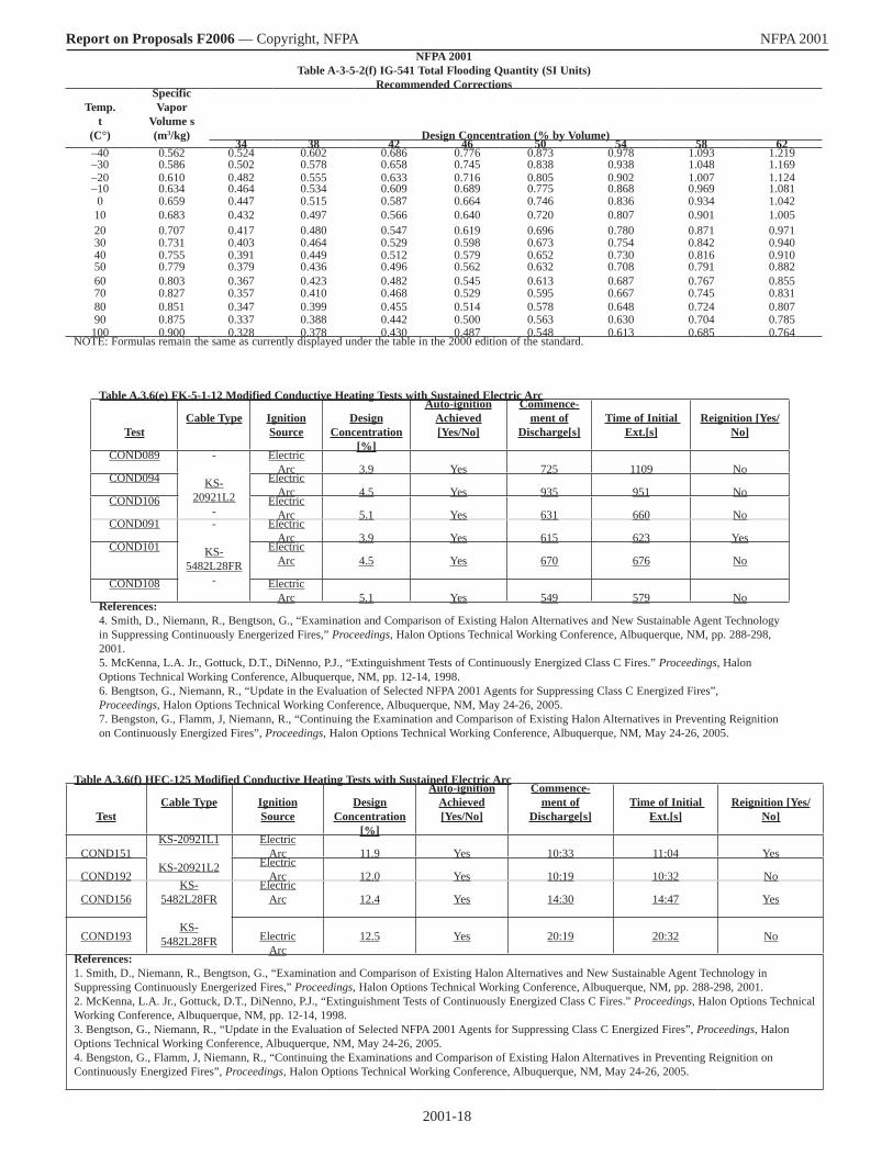
2001-18
Report on Proposals F2006 — Copyright, NFPA NFPA 2001 NFPA 2001
Table A-3-5-2(f) IG-541 Total Flooding Quantity (SI Units)Recommended Corrections
Temp.t
(C°)
Specific Vapor
Volume s(m3/kg) Design Concentration (% by Volume)
34 38 42 46 50 54 58 62–40 0.562 0.524 0.602 0.686 0.776 0.873 0.978 1.093 1.219–30 0.586 0.502 0.578 0.658 0.745 0.838 0.938 1.048 1.169–20 0.610 0.482 0.555 0.633 0.716 0.805 0.902 1.007 1.124–10 0.634 0.464 0.534 0.609 0.689 0.775 0.868 0.969 1.0810 0.659 0.447 0.515 0.587 0.664 0.746 0.836 0.934 1.04210 0.683 0.432 0.497 0.566 0.640 0.720 0.807 0.901 1.00520 0.707 0.417 0.480 0.547 0.619 0.696 0.780 0.871 0.97130 0.731 0.403 0.464 0.529 0.598 0.673 0.754 0.842 0.94040 0.755 0.391 0.449 0.512 0.579 0.652 0.730 0.816 0.91050 0.779 0.379 0.436 0.496 0.562 0.632 0.708 0.791 0.88260 0.803 0.367 0.423 0.482 0.545 0.613 0.687 0.767 0.85570 0.827 0.357 0.410 0.468 0.529 0.595 0.667 0.745 0.83180 0.851 0.347 0.399 0.455 0.514 0.578 0.648 0.724 0.80790 0.875 0.337 0.388 0.442 0.500 0.563 0.630 0.704 0.785100 0.900 0.328 0.378 0.430 0.487 0.548 0.613 0.685 0.764
NOTE: Formulas remain the same as currently displayed under the table in the 2000 edition of the standard.
Table A.3.6(e) FK-5-1-12 Modified Conductive Heating Tests with Sustained Electric Arc
TestCable Type Ignition
SourceDesign
Concentration[%]
Auto-ignitionAchieved[Yes/No]
Commence-ment of
Discharge[s]Time of Initial
Ext.[s]Reignition [Yes/
No]
COND089 -
KS-20921L2
-
ElectricArc 3.9 Yes 725 1109 No
COND094 ElectricArc 4.5 Yes 935 951 No
COND106 ElectricArc 5.1 Yes 631 660 No
COND091 -
KS-5482L28FR
-
ElectricArc 3.9 Yes 615 623 Yes
COND101 ElectricArc 4.5 Yes 670 676 No
COND108 ElectricArc 5.1 Yes 549 579 No
References:4. Smith, D., Niemann, R., Bengtson, G., “Examination and Comparison of Existing Halon Alternatives and New Sustainable Agent Technology in Suppressing Continuously Energerized Fires,” Proceedings, Halon Options Technical Working Conference, Albuquerque, NM, pp. 288-298, 2001.5. McKenna, L.A. Jr., Gottuck, D.T., DiNenno, P.J., “Extinguishment Tests of Continuously Energized Class C Fires.” Proceedings, Halon Options Technical Working Conference, Albuquerque, NM, pp. 12-14, 1998.6. Bengtson, G., Niemann, R., “Update in the Evaluation of Selected NFPA 2001 Agents for Suppressing Class C Energized Fires”, Proceedings, Halon Options Technical Working Conference, Albuquerque, NM, May 24-26, 2005.7. Bengston, G., Flamm, J, Niemann, R., “Continuing the Examination and Comparison of Existing Halon Alternatives in Preventing Reignition on Continuously Energized Fires”, Proceedings, Halon Options Technical Working Conference, Albuquerque, NM, May 24-26, 2005.
Table A.3.6(f) HFC-125 Modified Conductive Heating Tests with Sustained Electric Arc
TestCable Type Ignition
SourceDesign
Concentration[%]
Auto-ignitionAchieved[Yes/No]
Commence-ment of
Discharge[s]Time of Initial
Ext.[s]Reignition [Yes/
No]
COND151KS-20921L1
KS-20921L2
ElectricArc 11.9 Yes 10:33 11:04 Yes
COND192Electric
Arc 12.0 Yes 10:19 10:32 No
COND156KS-
5482L28FR
KS-5482L28FR
ElectricArc 12.4 Yes 14:30 14:47 Yes
COND193 ElectricArc
12.5 Yes 20:19 20:32 No
References:1. Smith, D., Niemann, R., Bengtson, G., “Examination and Comparison of Existing Halon Alternatives and New Sustainable Agent Technology in Suppressing Continuously Energerized Fires,” Proceedings, Halon Options Technical Working Conference, Albuquerque, NM, pp. 288-298, 2001.2. McKenna, L.A. Jr., Gottuck, D.T., DiNenno, P.J., “Extinguishment Tests of Continuously Energized Class C Fires.” Proceedings, Halon Options Technical Working Conference, Albuquerque, NM, pp. 12-14, 1998.3. Bengtson, G., Niemann, R., “Update in the Evaluation of Selected NFPA 2001 Agents for Suppressing Class C Energized Fires”, Proceedings, Halon Options Technical Working Conference, Albuquerque, NM, May 24-26, 2005.4. Bengston, G., Flamm, J, Niemann, R., “Continuing the Examinations and Comparison of Existing Halon Alternatives in Preventing Reignition on Continuously Energized Fires”, Proceedings, Halon Options Technical Working Conference, Albuquerque, NM, May 24-26, 2005.
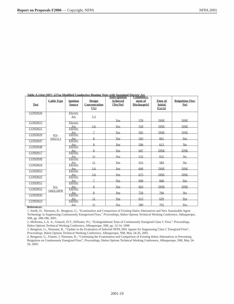
2001-19
Report on Proposals F2006 — Copyright, NFPA NFPA 2001
Table A.3.6(g) HFC-227ea Modified Conductive Heating Tests with Sustained Electric Arc
TestCable Type Ignition
SourceDesign
Concentration[%]
Auto-ignitionAchieved[Yes/No]
Commence-ment of
Discharge[s]Time of Initial Ext.[s]
Reignition [Yes/No]
COND026
KS-20921L2
ElectricArc 5.3
Yes 578 DNE DNECOND015 Electric
Arc 5.6 Yes 530 DNE DNECOND021 Electric
Arc 7 Yes 582 DNE DNECOND020 Electric
Arc 8 Yes 543 661 YesCOND047 Electric
Arc 8 Yes 596 615 NoCOND048 Electric
Arc 8 Yes 647 DNE DNECOND017 Electric
Arc 11 Yes 532 832 NoCOND049 Electric
Arc 11 Yes 555 584 NoCOND024
KS-5482L28FR
ElectricArc 5.6 Yes 606 DNE DNE
COND053 ElectricArc 5.6 Yes 675 DNE DNE
COND025 ElectricArc 7 Yes 608 848 Yes
COND051 ElectricArc 8 Yes 663 DNE DNE
COND052 ElectricArc 8 Yes 750 766 No
COND050 ElectricArc 11 Yes 615 639 Yes
COND023 ElectricArc 11 Yes 580 702 Yes
References:1. Smith, D., Niemann, R., Bengtson, G., “Examination and Comparison of Existing Halon Alternatives and New Sustainable Agent Technology in Suppressing Continuously Energerized Fires,” Proceedings, Halon Options Technical Working Conference, Albuquerque, NM, pp. 288-298, 2001.2. McKenna, L.A. Jr., Gottuck, D.T., DiNenno, P.J., “Extinguishment Tests of Continuously Energized Class C Fires.” Proceedings, Halon Options Technical Working Conference, Albuquerque, NM, pp. 12-14, 1998.3. Bengtson, G., Niemann, R., “Update in the Evaluation of Selected NFPA 2001 Agents for Suppressing Class C Energized Fires”, Proceedings, Halon Options Technical Working Conference, Albuquerque, NM, May 24-26, 2005.4. Bengston, G., Flamm, J, Niemann, R., “Continuing the Examination and Comparison of Existing Halon Alternatives in Preventing Reignition on Continuously Energized Fires”, Proceedings, Halon Options Technical Working Conference, Albuquerque, NM, May 24-26, 2005.

2001-20
Report on Proposals F2006 — Copyright, NFPA NFPA 2001
Table A.3.6(h) HFC-236fa Modified Conductive Heating Tests with Sustained Electric Arc
TestCable Type Ignition
SourceDesign
Concentration[%]
Auto-ignitionAchieved[Yes/No]
Commence-ment of
Discharge[s]Time of Initial
Ext.[s]Reignition [Yes/
No]
COND149
KS-20921L2
ElectricArc 8.0 Yes 11:30 11:36 Yes
COND150 ElectricArc 6.8 Yes 10:56 DNE DNE
COND151 ElectricArc 7.5 Yes 11:26 DNE DNE
COND152 ElectricArc 7.5 Yes 12:07 13:20 Yes
COND153 ElectricArc 7.5 Yes 9:59 10.3 Yes
COND154 ElectricArc 8.0 Yes 11:26 11:32 No
COND155 ElectricArc 8.0 Yes 10:59 11:30 No
COND194 ElectricArc 8.0 Yes 11:13 11:58 No
COND144
KS-5482L28FR
ElectricArc 6.5 Yes 6:06 DNE DNE
COND145 ElectricArc 8.0 Yes 10:43 DNE DNE
COND146 ElectricArc 8.5 Yes 10:03 10:15 No
COND147 ElectricArc 8.5 Yes 12:45 13:00 No
COND148 ElectricArc 8.5 Yes 12:05 12:14 No
COND195 ElectricArc 8.5 Yes 12:06 12:18 No
References:1. Smith, D., Niemann, R., Bengtson, G., “Examination and Comparison of Existing Halon Alternatives and New Sustainable Agent Technology in Suppressing Continuously Energerized Fires,” Proceedings, Halon Options Technical Working Conference, Albuquerque, NM, pp. 288-298, 2001.2. McKenna, L.A. Jr., Gottuck, D.T., DiNenno, P.J., “Extinguishment Tests of Continuously Energized Class C Fires.” Proceedings, Halon Options Technical Working Conference, Albuquerque, NM, pp. 12-14, 1998.3. Bengtson, G., Niemann, R., “Update in the Evaluation of Selected NFPA 2001 Agents for Suppressing Class C Energized Fires”, Proceedings, Halon Options Technical Working Conference, Albuquerque, NM, May 24-26, 2005.4. Bengston, G., Flamm, J, Niemann, R., “Continuing the Examination and Comparison of Existing Halon Alternatives in Preventing Reignition on Continuously Energized Fires”, Proceedings, Halon Options Technical Working Conference, Albuquerque, NM, May 24-26, 2005.

2001-21
Report on Proposals F2006 — Copyright, NFPA NFPA 2001 ________________________________________________________________ 2001-64 Log #53 Final Action: Reject (Table A.4.1.4.1) ________________________________________________________________ Submitter: John Spalding, Healey Fire Protection Inc. / Rep. Fire Suppression Systems Association, Baltimore MD Recommendation: Table needs completion and harmonizing: Table A.4.1.4.1 needs to be completed to include data for each combination of gent, superpressure, fill density, container pressure rating. Substantiation: Table is incomplete and/or in error and needs to be corrected. Committee Meeting Action: Reject Committee Statement: No recommended text provided.
_______________________________________________________________ 2001-65 Log #31 Final Action: Accept (A.5.3.7 (New) ) ________________________________________________________________ Submitter: Jeffrey L. Harrington, Harrington Group, Inc. Recommendation: Add the following new annex paragraph A.5.3.7: A.5.3.7 Designers should evaluate enclosures to determine whether they can resist the momentary pressure changes that occur during the discharge of a clean agent fire extinguishing system. The analysis should include a recommendation of whether or not a discharge pressure relief device is needed in order that the enclosure be able to withstand the peak pressure developed relative to ambient. Annex D contains information for evaluating enclosures. Substantiation: The failure of an enclosure due to discharge pressures that exceed the ability of the enclosure to remain intact presents a safety concern for people in or near the protected space. Steps must be taken to assure safety. Committee Meeting Action: Accept ________________________________________________________________ 2001-66 Log #7 Final Action: Accept in Principle in Part (A.5.4.2) ________________________________________________________________ Submitter: Robert T. Wickham, Wickham Associates Recommendation: Renumber paragraph A.5.4.2 to A.5.4.2.1 and modify it to read as follows: A.5.4.2. 1 Cup burner testing in the past has involved a variety of techniques, apparatus, and investigators. A standard cup burner test procedure with defined apparatus has now been established and is outlined in Annex B. Table A.5.4.2 . 1 presents cup burner flame extinguishing concentrations for n- heptane determined both by cup burner and room testing as reported in the referenced documents. Substantiation: The information presented in the current Table A.5.4.2 predates more current data generated as a result of efforts to standardize the cup burner apparatus and laboratory procedures and attempts to correlate cup burner and room scale fire test results. The information proposed in the new Table A.5.4.2.1 is more current and its source has a higher degree of transparency than the existing information. Committee Meeting Action: Accept in Principle in Part Renumber paragraph A.5.4.2 to A.5.4.2.1 and modify it to read as follows: A.5.4.2. 1 Cup burner testing in the past has involved a variety of techniques, apparatus, and investigators. A standard cup burner test procedure with defined apparatus has now been established and is outlined in Annex B. Table A.5.4.2 . 1 presents cup burner flame extinguishing concentrations for n- heptane determined by cup burner as reported in the referenced documents. Committee Statement: The committee wanted to further review room test data. ________________________________________________________________ 2001-67 Log #8 Final Action: Accept in Principle (A.5.4.2) ________________________________________________________________ Submitter: Robert T. Wickham, Wickham Associates Recommendation: Delete Table A.5.4.2 and replace with new Table A.5.4.2.1 along with a list of data references. Table A.5.4.2 n Heptane Cup Burner Extinguishment Concentrations Agent Cup Burner Value FC 3-1-10 5.5 FIC13I1* 3.2 FK 5-1-12 4.5 HCFC Blend A 9.9 HCFC 124 6.6 HFC 125 8.7
HFC 227ea 6.6 HRC 23 12.9 HFC 236fa 6.3 IG 01 42 IG 100 * 31 IG 541 31 IG 55 35 Note: A value of cup burner extinguishing concentration of 6.7 percent for HCF 227ea for commercial heptane fuel. *Not derived from standardized cup burner method
References for data in Table A.5.4.2.1 1. Harrison, Matthew A. and Robin, Mark L., PhD., “Cup Burner Testing of Heptane with Iodotrifluoromethane in Accordance with ISO 14520-1, “report HAI-8716A, Hughes Associates, Inc., April 8, 2002 2. Acknowledgment of Cup Burner Measurements on NOVEC 1230, “Test Report No. YN 02 6321, Centre National de Prevention et de Protection, Saint Marcel, France: September 13, 2002 3. Harrison, Matthew A. and Robin, Mark L., PhD., “Cup Burner Testing of Heptane with NAF-S-III in Accordance with ISO 14520-1, “Report HAI-8719, Hughes Associates, Inc., May 28, 2002. 4. Harrison, M.A., and Robin, M. L., “Cup Burner Testing of Heptane with HFC-125 and HFC-236fa in Accordance with ISO 14520-1,” Report HAI-8715-A, Hughes Associates, Inc., West Lafayette, IN, February 14, 2002 5. Mark L. Robin, PhD., “Cup Burner Testing of Heptane with HFC-227ea in Accordance with ISO 14520-1,” Report HAI-8711-B. Hughes Associates Inc., West Lafayette, IN, December 30, 2001. 6. Harrison, Matthew A. and Robin, Mark L., PhD., “Cup Burner Testing of Heptane with HFC-23 in Accordance with ISO 14520-1, “ Report HAI-8720A, Hughes Associates, Inc., May 8, 2002. 7. Harrison, M.A., and Robin, M. L., “Cup Burner Testing of Heptane with HFC-125 and HFC-236fa in Accordance with ISO 1420-1,” Report HAI-8715-A. Hughes Associates, Inc., West Lafayette, IN, February 14, 2002. 8. “Attestation of Test Results Following the Methods for Determination of Extinguishing Concentrations in ISO 14520-1 (2000) Extinguishing Agent: Argon: ISO 14520-12,” VdS Schadenverhutung, Koln, Germany, 12 December 2001. 9. Yamane, Kenji, “Cup Burner Testing Report with IG-100 in Accordance with ISO 14520-1:2000(E) Annex B,” National Maritime Research Institute, Independent Administrative Institution, Report No. RA-001: March 6, 2002. 10. “Cup Burner Class B Extinguishing Tests of Argonite Clean Extinguishing Agent,” Project 3014580, Class 5611, FM Approvals, July 9, 2002. 11. Yves Fleurimond, “Cup Burner Fire Test on Commercial Heptane with Inergen in accordance with ISO 14520,” File EX4510, Project 02NK13115, Underwriters Laboratories, Inc., Northbrook, IL May 10, 2002 12. Robin, M. L., Ouelette J. Hammett, A Ouelette, R. and Kennedy J., “Wood Crib and Heptane Pan Fire Testing of CF3I in Accordance with ISO 14520-1” Report HAI-8721B Hughes Associates, Inc., West Lafayette, IN, August 30, 2002. 13. Report, “Wood Crib and Heptane Pan Testing with 3MTM NovecTM 1230 Fire Protection Fluid in Accordance with ISO 14520-1-2000(E),” Underwriters Laboratories Inc., Northbrook, IL: September 6, 2002. 14. Borghetti, Luciano, “Report on fire testing of Safety Hi-Tech NAF S III According to International Standard ISO 14520-1 First Edition 2000-08-001, Annex C Wood Crib and Heptane Pan, “Hughes Associates Europe, srl Report HAE-May 2, 2002. 15. Robin, M. L., Ouelette, J., Hammett, A. Ouelette, R. and Kennedy, J., “Wood Crib and Heptane Pan Fire Testing of HFC-125 and HFC-236fa in Accordance with ISO 14520-1,” Report HAI -8715-B, Hughes Associates, Inc., West Lafayette, IN, February 14, 2002 16. Mark L. Robin, PhD., “Wood Crib and Heptane Pan Fire Testing of HFC-227ea in Accordance with ISO 14520-1”, Report HAI-8711-A, Hughes Associates, Inc., West Lafayette, IN, December 30, 2001. 17. L. Jackman, “Test Report, FE13 Gaseous Extinguishing Testing to BS ISO 14520:2000 and ISO/TR 20885:2001(E), “Test Report 206579, BRE Fire and Risk Sciences Division, January 9, 2002. 18. Robin, M. L., Ouelette, J., Hammett, A., Ouelette, R. and Kennedy. J., “Wood Crib and Heptane Pan Fire Testing of HFC-125 and HFC-236fa in Accordance with ISO 14520-1,” Report HAI-8715-B, Hughes Associates, Inc., West lafayette, IN, February 14, 2002. 19. English language report extract of “Test Report No. CHL 02051 on the Extinguishing Tests with the Extinguishing Agent Argon according to ISO
Table A.5.4.3.1 – Heptane Flame Extinguishing Concentrations (vol %)Heptane Fire Test
FIC-13I1
FK-5-1-12
HCFCBlendA
HFC-125
HFC-227ea
HFC-23
HFC-236fa
IG-01
IG-100
IG-55
IG-541
Cup burnerRoom test
3.51
3.5124.52
4.41310.03
9.9149.34
9.3156.75
6.91612.66
12.3176.57
7.51839.28
33.71933.69
33.62036.510
30.22131.711
29.622
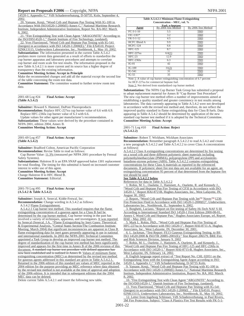
2001-22
Report on Proposals F2006 — Copyright, NFPA NFPA 2001 14520-1, Appendix C,” VdS Schadenverhutung, D-50735, Koln, September 4, 2002. 20. Yamane, Kenji, “Wood Crib and Heptane Pan Testing With IG-100 in Accordance With ISO14520-1:2000(E) Annex C,” National Maritime Research Institute, Independent Administrative Institution, Report No. RA-002: March 8, 2002. 21. “Fire Extinguishing Test with Clean Agent “ARAGONITE” According to the ISO/DIS14520-1,” Danish Institute of Fire Technology, (undated). 22. Yves Fluerimond, “Wood Crib and Heptane Pan Testing with IG-541 (Inergen) in accordance with ISO 14520-1:2000(E),” File EX4510, Project 02NK13115, Underwriters Laboratories, Inc., Northbrook, L, May 10, 2002. Substantiation: The information presented in the current Table A.5.4.2 predates more current data generated as a result of efforts to standardize the cup burner apparatus and laboratory procedures and attempts to correlate cup burner and room scale fire test results. The information proposed in the new Table A.5.4.2.1 is more current and its source has a higher degree of transparency than the existing information. Committee Meeting Action: Accept in Principle Make the recommended changes and add all the material except the second line of the table concerning the room test data. Committee Statement: The committee wanted to further review room test data. ________________________________________________________________ 2001-68 Log #24 Final Action: Accept (Table A.5.4.2) ________________________________________________________________ Submitter: Howard S. Hammel, DuPont Fluoroproducts Recommendation: Replace HFC-227ea cup burner value of 6.6 with 6.9. Replace HFC-236fa cup burner value of 6.3 with 6.6. Update values for other agent per manufacturer’s recommendation. Substantiation: These values were derived by the procedure contained in NFPA 2001, edition 2004, Annex B. Committee Meeting Action: Accept ________________________________________________________________ 2001-69 Log #57 Final Action: Accept (Table A.5.4.2) ________________________________________________________________ Submitter: Bradford Colton, American Pacific Corporation Recommendation: Revise Table to read as follows: Cup Burner Value: 11.3% (measured per NFPA 2001 procedure by Fenwal Safety Systems). Substantiation: Halotron II is an EPA SNAP approved halon 1301 replacement for total flooding. The timing for this submittal is based on increased customer interest in wider use of this agent. Committee Meeting Action: Accept Change Halotron II to HFC Blend B. Committee Statement: Editorial. ________________________________________________________________ 2001-70 Log #95 Final Action: Accept (A.5.4.2 & Table A.5.4.2) ________________________________________________________________ Submitter: Joseph A. Senecal, Kidde-Fenwal, Inc. Recommendation: Change wording in A.5.4.2 as follows: A.5.4.2 Flame Extinguishment. A.5.4.2.1 Cup burner test method. This standard requires that the flame extinguishing concentration of a gaseous agent for a Class B fuel be determined by the cup burner method. Cup burner testing in the past has involved a variety of techniques, apparatus, and investigators. It was reported by Senecal (Senecal, J.A., “Flame Extinguishing by Inert Gases: Theoretical & Experimental Analysis, “Central States Section/The Combustion Institute Meeting, March 2004) that significant inconsistencies are apparent in Class B flame extinguishing data for inert gases presently appearing in use in national and international standards. In 2003 the NFPA 2001 Technical Committee appointed a Task Group to develop an improved cup burner test method. The degree of standardization of the cup burner test method has been significantly improved and appears for the first time in Annex B of the 2006 revision of this document. A standard cup burner test procedure with defined apparatus has now been established and is outlined in Annex B. Values of minimum flame extinguishing concentration (MEC) as determined by the revised test method for gaseous agents addressed in this standard are given in Table A.5.4.2.1. Retained in the 2006 edition of this standard are values of MEC reported in the 2004 edition for the purpose providing an MEC reference where data obtained by the revised test method is not available at the time of approval and adoption of the 2006 edition. It is intended that in subsequent editions that the 2004 MEC data can be deleted. Delete current Table A.5.4.2.1 and insert the following new table.
Substantiation: The NFPA Cup Burner Task Group has submitted a proposal to adopt replacement material for Annex B “Cup Burner Test Procedure”. The new cup burner test method offers a number of improvements aimed at establishing a quality standard and greater consistency in test results among laboratories. The data currently appearing in Table A.5.4.2 were not developed in accordance with the revised test method and, therefore, do not reflect the improved quality standard in flame extinguishing data for Class B fuels. Data appearing in Table A.5.4.2 should be determined by application of the new standard cup burner test method if it is adopted by the Technical Committee. Committee Meeting Action: Accept ________________________________________________________________ 2001-71 Log #10 Final Action: Reject (A.5.4.2.2) ________________________________________________________________ Submitter: Robert T. Wickham, Wickham Associates Recommendation: Renumber paragraph A.5.4.2.2 to read A.5.4.2 and create a new paragraph A.5.4.2.2 and Table A.5.4.2.2 to cover Class A concentrations as follows): A.5.4.2.2 Class A extinguishing concentrations are determined by fire testing on a wood crib and three different polymeric sheet materials including polymethylmethacrylate (PMMA), polypropylene (PP) and acrylonitrile-butadiene-styrene polymer (ABS). Table A.5.4.2.2 contains extinguishing concentrations for these Class A materials as reported in the referenced documents. If polymeric sheet fire test data are not available for an agent, an extinguishing concentration 95 percent of that determined from the heptane fire test should be usedSee Table A.5.4.2.2 belowReferences for data in Table A.5.4.2.2 1. Robin, M. L., Ouelette, J., Hammett, A., Ouelette, R. and Kennedy J., “Wood Crib and Heptane Pan Fire Testing of CF3I in Accordance with ISO 14520-1,” Report HAI-8721B, Hughes Associates, Inc., West Lafayette, IN, August 30, 2002. 2. Report, “Wood Crib and Heptane Pan Testing with 3mTM NovecTM 1230 Fire Protection Fluid in Accordance with ISO 14520-1-2000(E)”, Underwriters Laboratories Inc., Northbrook, IL; September 6, 2002. 3. Borghetti, Luciano, “Report on fire testing of Safety Hi-Tech NAF S III According to International Standard ISO 14520-1 First Edition 2000-08-01, Annex C Wood Crib and Heptane Pan,” Hughes Associates Europe, srl, Report HAE - May 2002 -02. 5. Mark L. Robin, PhD., “Wood Crib and Heptane Pan Fire Testing of HFC-227ea in Accordance with ISO 14520-1”, Report HAI-8711-A. Hughes Associates, Inc., West Lafayette, IN, December 30, 2001. 6. L. Jackman, “Test Report: FE13 Gaseous Extinguishing Testing, to BS ISO 14520:2000 & ISO/TR 20885-2001(E),” Test Report 206579, BRE Fire and Risk Sciences Division, January 9, 2002 7. Robin, M. L., Ouelette, J., Hammett, A. Ouelette, R. and Kennedy, J., “Wood Crib and Heptane Pan Fire Testing of HFC-125 and HFC-236fa in Accordance with ISO 14520-1.” Report HAI-8715-B, Hughes Associates, Inc., West Lafayette, IN, February 14, 2002. 8. English language report extract of “Test Report No. CHL 02051 on the Extinguishing Tests with the Extinguishing Agent Argon according to ISO 14520-1, Appendix C:” VdS Schadenverhutung, D-50735 Koln. 9. Yamane, Kenji, “Wood Crib and Heptane Pan Testing with IG-100 in Accordance with ISO 14520-1:2000(E) Annex C,” National Maritime Research Institute, Independent Administrative Institution, Report No. RA_002: March 8, 2002. 10. “Fire Extinguishing Test with Clean Agent “ARGONITE” According to the ISO/DIS14520-1,” Danish Institute of Fire Technology, (undated). 11. Yves Fluerimond, “Wood Crib and Heptane Pan Testing with IG-541 (Inergen) in accordance with ISO 14520-1:2000(E_,” File EX4510, Project 02NK13115, Underwriters Laboratories, Inc., Northbrook, IL, May 10, 2002. 12. Letter from Ingeborg Schlosser, VdS Schadenverhutung, to Paul Rivers, 3M Fire Protection, Subject: “Class A Plastics Fire Test Results with FK-5-1-
Table A.5.4.2.1 Minimum Flame ExtinguishingConcentration – MEC, vol. %
Fuel: n-heptaneAgent By 2004 Test Method By 2006 Test Method
FC-3-1-10 5.5 TBDFIC-13l1* 3.2 TBDFK-5-1-12 4.5 TBDHCFC Blend A 9.9 TBDHCFC-124 6.6 TBDHFC-125 8.7 TBDHFC-227ea 6.6(1) TBDHFC-23 12.9 TBDHFC-236fa 6.3 TBDIG-01 42 TBDIG-100 31(2) TBDIG-541 31 TBDIG-55 35 TBDNote 1: A value of cup burner extinguishing concentration of 6.7 percent for HCF-227ea for commercial heptane fuel.Note 2: Not derived from standardized cup burner method.
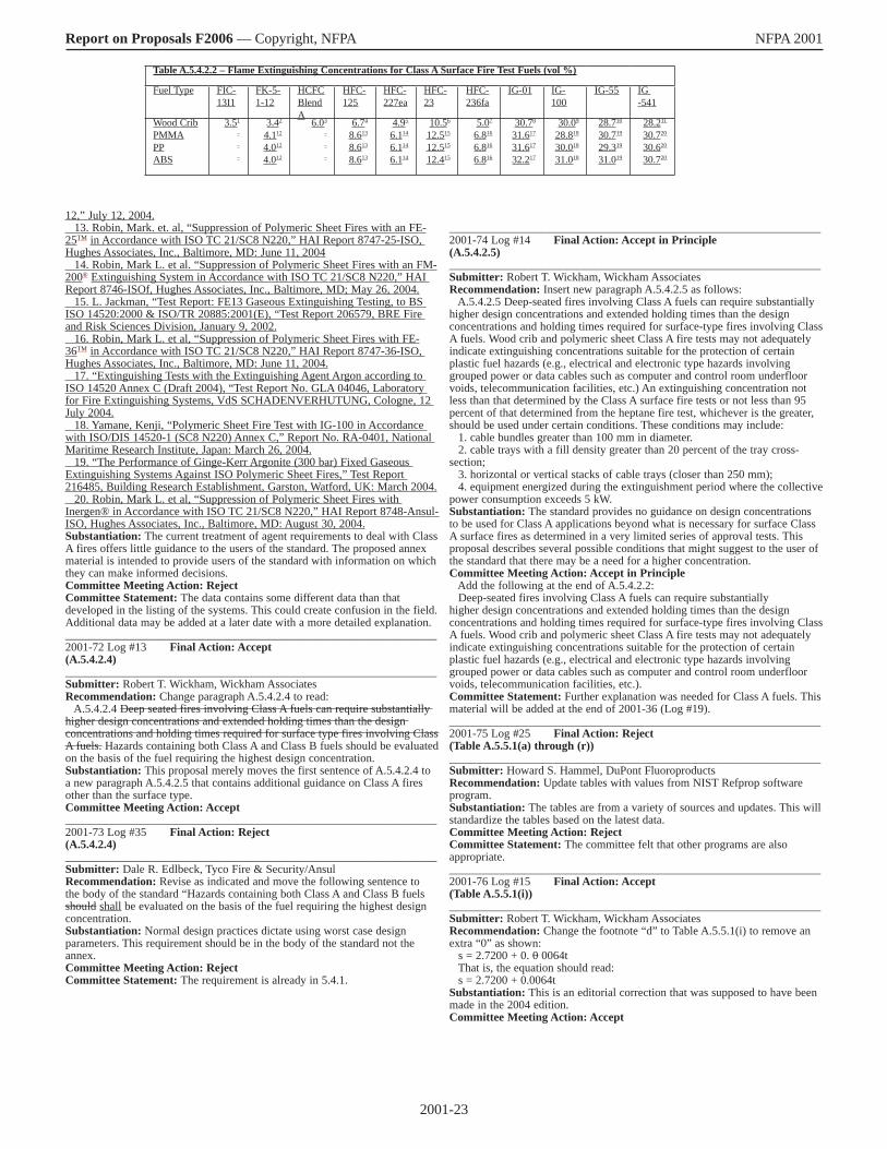
2001-23
Report on Proposals F2006 — Copyright, NFPA NFPA 2001
12,” July 12, 2004. 13. Robin, Mark. et. al, “Suppression of Polymeric Sheet Fires with an FE-25TM in Accordance with ISO TC 21/SC8 N220,” HAI Report 8747-25-ISO, Hughes Associates, Inc., Baltimore, MD: June 11, 2004 14. Robin, Mark L. et al. “Suppression of Polymeric Sheet Fires with an FM-200® Extinguishing System in Accordance with ISO TC 21/SC8 N220,” HAI Report 8746-ISOf, Hughes Associates, Inc., Baltimore, MD; May 26, 2004. 15. L. Jackman, “Test Report: FE13 Gaseous Extinguishing Testing, to BS ISO 14520:2000 & ISO/TR 20885:2001(E), “Test Report 206579, BRE Fire and Risk Sciences Division, January 9, 2002. 16. Robin, Mark L. et al, “Suppression of Polymeric Sheet Fires with FE-36TM in Accordance with ISO TC 21/SC8 N220,” HAI Report 8747-36-ISO, Hughes Associates, Inc., Baltimore, MD: June 11, 2004. 17. “Extinguishing Tests with the Extinguishing Agent Argon according to ISO 14520 Annex C (Draft 2004), “Test Report No. GLA 04046, Laboratory for Fire Extinguishing Systems, VdS SCHADENVERHUTUNG, Cologne, 12 July 2004. 18. Yamane, Kenji, “Polymeric Sheet Fire Test with IG-100 in Accordance with ISO/DIS 14520-1 (SC8 N220) Annex C,” Report No. RA-0401, National Maritime Research Institute, Japan: March 26, 2004. 19. “The Performance of Ginge-Kerr Argonite (300 bar) Fixed Gaseous Extinguishing Systems Against ISO Polymeric Sheet Fires,” Test Report 216485, Building Research Establishment, Garston, Watford, UK: March 2004. 20. Robin, Mark L. et al, “Suppression of Polymeric Sheet Fires with Inergen® in Accordance with ISO TC 21/SC8 N220,” HAI Report 8748-Ansul-ISO, Hughes Associates, Inc., Baltimore, MD: August 30, 2004. Substantiation: The current treatment of agent requirements to deal with Class A fires offers little guidance to the users of the standard. The proposed annex material is intended to provide users of the standard with information on which they can make informed decisions. Committee Meeting Action: Reject Committee Statement: The data contains some different data than that developed in the listing of the systems. This could create confusion in the field. Additional data may be added at a later date with a more detailed explanation. ________________________________________________________________ 2001-72 Log #13 Final Action: Accept (A.5.4.2.4) ________________________________________________________________ Submitter: Robert T. Wickham, Wickham Associates Recommendation: Change paragraph A.5.4.2.4 to read: A.5.4.2.4 Deep seated fires involving Class A fuels can require substantially higher design concentrations and extended holding times than the design concentrations and holding times required for surface type fires involving Class A fuels. Hazards containing both Class A and Class B fuels should be evaluated on the basis of the fuel requiring the highest design concentration. Substantiation: This proposal merely moves the first sentence of A.5.4.2.4 to a new paragraph A.5.4.2.5 that contains additional guidance on Class A fires other than the surface type. Committee Meeting Action: Accept ________________________________________________________________ 2001-73 Log #35 Final Action: Reject (A.5.4.2.4) ________________________________________________________________ Submitter: Dale R. Edlbeck, Tyco Fire & Security/Ansul Recommendation: Revise as indicated and move the following sentence to the body of the standard “Hazards containing both Class A and Class B fuels should shall be evaluated on the basis of the fuel requiring the highest design concentration. Substantiation: Normal design practices dictate using worst case design parameters. This requirement should be in the body of the standard not the annex. Committee Meeting Action: Reject Committee Statement: The requirement is already in 5.4.1.
________________________________________________________________ 2001-74 Log #14 Final Action: Accept in Principle (A.5.4.2.5) ________________________________________________________________ Submitter: Robert T. Wickham, Wickham Associates Recommendation: Insert new paragraph A.5.4.2.5 as follows: A.5.4.2.5 Deep-seated fires involving Class A fuels can require substantially higher design concentrations and extended holding times than the design concentrations and holding times required for surface-type fires involving Class A fuels. Wood crib and polymeric sheet Class A fire tests may not adequately indicate extinguishing concentrations suitable for the protection of certain plastic fuel hazards (e.g., electrical and electronic type hazards involving grouped power or data cables such as computer and control room underfloor voids, telecommunication facilities, etc.) An extinguishing concentration not less than that determined by the Class A surface fire tests or not less than 95 percent of that determined from the heptane fire test, whichever is the greater, should be used under certain conditions. These conditions may include: 1. cable bundles greater than 100 mm in diameter. 2. cable trays with a fill density greater than 20 percent of the tray cross-section; 3. horizontal or vertical stacks of cable trays (closer than 250 mm); 4. equipment energized during the extinguishment period where the collective power consumption exceeds 5 kW. Substantiation: The standard provides no guidance on design concentrations to be used for Class A applications beyond what is necessary for surface Class A surface fires as determined in a very limited series of approval tests. This proposal describes several possible conditions that might suggest to the user of the standard that there may be a need for a higher concentration. Committee Meeting Action: Accept in Principle Add the following at the end of A.5.4.2.2: Deep-seated fires involving Class A fuels can require substantially higher design concentrations and extended holding times than the design concentrations and holding times required for surface-type fires involving Class A fuels. Wood crib and polymeric sheet Class A fire tests may not adequately indicate extinguishing concentrations suitable for the protection of certain plastic fuel hazards (e.g., electrical and electronic type hazards involving grouped power or data cables such as computer and control room underfloor voids, telecommunication facilities, etc.). Committee Statement: Further explanation was needed for Class A fuels. This material will be added at the end of 2001-36 (Log #19). ________________________________________________________________ 2001-75 Log #25 Final Action: Reject (Table A.5.5.1(a) through (r)) ________________________________________________________________ Submitter: Howard S. Hammel, DuPont Fluoroproducts Recommendation: Update tables with values from NIST Refprop software program. Substantiation: The tables are from a variety of sources and updates. This will standardize the tables based on the latest data. Committee Meeting Action: Reject Committee Statement: The committee felt that other programs are also appropriate. ________________________________________________________________ 2001-76 Log #15 Final Action: Accept (Table A.5.5.1(i)) ________________________________________________________________ Submitter: Robert T. Wickham, Wickham Associates Recommendation: Change the footnote “d” to Table A.5.5.1(i) to remove an extra “0” as shown: s = 2.7200 + 0. 0 0064t That is, the equation should read: s = 2.7200 + 0.0064t Substantiation: This is an editorial correction that was supposed to have been made in the 2004 edition. Committee Meeting Action: Accept
Table A.5.4.2.2 – Flame Extinguishing Concentrations for Class A Surface Fire Test Fuels (vol %)
Fuel Type FIC-13I1
FK-5-1-12
HCFCBlendA
HFC-125
HFC-227ea
HFC-23
HFC-236fa
IG-01 IG-100
IG-55 IG -541
Wood CribPMMAPPABS
3.51
–
–
–
3.42
4.112
4.012
4.012
6.03
–
–
–
6.74
8.613
8.613
8.613
4.95
6.114
6.114
6.114
10.56
12.515
12.515
12.415
5.07
6.816
6.816
6.816
30.78
31.617
31.617
32.217
30.09
28.818
30.018
31.018
28.710
30.719
29.319
31.019
28.211
30.720
30.620
30.720
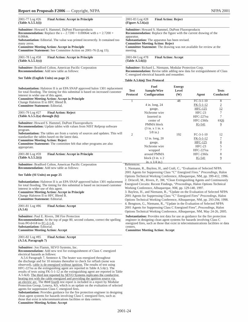
2001-24
Report on Proposals F2006 — Copyright, NFPA NFPA 2001 ________________________________________________________________ 2001-77 Log #26 Final Action: Accept in Principle (Table A.5.5.1(i)) ________________________________________________________________ Submitter: Howard S. Hammel, DuPont Fluoroproducts Recommendation: Replace the s – 2.7200 + 0.00064t with s = 2.7200 + 0.0064t. Substantiation: Editorial. The value was printed incorrectly. It contained too many zeros. Committee Meeting Action: Accept in Principle Committee Statement: See Committee Action on 2001-76 (Log 15). ________________________________________________________________ 2001-78 Log #58 Final Action: Accept in Principle (Table A.5.5.1(s)) ________________________________________________________________ Submitter: Bradford Colton, American Pacific Corporation Recommendation: Add new table as follows: See Table (English Units) on page 25 Substantiation: Halotron II is an EPA SNAP approved halon 1301 replacement for total flooding. The timing for this submittal is based on increased customer interest in wider use of this agent. Committee Meeting Action: Accept in Principle Change Halotron II to HFC Blend B. Committee Statement: Editorial. ________________________________________________________________ 2001-79 Log #27 Final Action: Reject (Table A.5.5.2(a) through (h)) ________________________________________________________________ Submitter: Howard S. Hammel, DuPont Fluoroproducts Recommendation: Update tables with values from NIST Refprop software program. Substantiation: The tables are from a variety of sources and updates. This will standardize the tables based on the latest data. Committee Meeting Action: Reject Committee Statement: The committee felt that other programs are also appropriate. ________________________________________________________________ 2001-80 Log #59 Final Action: Accept in Principle (Table A.5.5.2(t)) ________________________________________________________________ Submitter: Bradford Colton, American Pacific Corporation Recommendation: Add new table as follows: See Table (SI Units) on page 25 Substantiation: Halotron II is an EPA SNAP approved halon 1301 replacement for total flooding. The timing for this submittal is based on increased customer interest in wider use of this agent. Committee Meeting Action: Accept in Principle Change Halotron II to HFC Blend B. Committee Statement: Editorial. ________________________________________________________________ 2001-81 Log #86 Final Action: Accept (A.5.6) ________________________________________________________________ Submitter: Paul E. Rivers, 3M Fire Protection Recommendation: At the top of page 80, second column, correct the spelling from FC-2-1.8 to FC-2-1-8. Substantiation: Editorial. Committee Meeting Action: Accept ________________________________________________________________ 2001-82 Log #85 Final Action: Accept (A.5.6, Paragraph 7) ________________________________________________________________ Submitter: Jon Flamm, SEVO Systems, Inc. Recommendation: Add new text for extinguishment of Class C energized electrical hazards as follows: A.5.6 Paragraph 7, Sentence 4, The heater was energized throughout the discharge and for 10 minutes thereafter to check for reflash (none was observed), cable is de-energized without ignition. The results of test using HFC-227ea as the extinguishing agent are reported in Table A.5.6(c). The results of tests using FK-5-1-12 as the extinguishing agent are reported in Table A.5.6(d). The third test reported by SEVO Systems replicates the conductive heating test with the cable energized and providing the ignition source via an electric arc. The third fourth test report is included in a report by Modular Protection Group, Lenexa, KS, which is an update on the evaluation of selected agents for suppression Class C energized fires. Substantiation: Provides guidance for the fire protection engineer in designing clean agent systems for hazards involving Class C energized fires, such as those that exist in telecommunications facilities or data centers. Committee Meeting Action: Accept
________________________________________________________________ 2001-83 Log #28 Final Action: Reject (Figure A.5.6(a)) ________________________________________________________________ Submitter: Howard S. Hammel, DuPont Fluoroproducts Recommendation: Replace the figure with the current drawing of the apparatus. Substantiation: The apparatus has been revised. Committee Meeting Action: Reject Committee Statement: The drawing was not available for review at the meeting. ________________________________________________________________ 2001-84 Log #78 Final Action: Accept (Table A.5.6(i)) ________________________________________________________________ Submitter: Richard L. Niemann, Modular Protection Corp. Recommendation: Revise table adding new data for extinguishment of Class C energized electrical hazards and renumber.
Substantiation: Provides test data for use as guidance for the fire protection engineer in designing clean agent systems for hazards involving Class C energized fires, such as those that exist in telecommunications facilities or data centers. Committee Meeting Action: Accept
Table A.5.6(ei) Test Protocol
TestProtocol
FuelSample/WireConfiguration
EnergyLevel(W) Agent
TestsConducted
14 in. long, 24
gauge,Nichrome wire
Inserted incenter of
PMMA block(3 in. x 1 in. x
5/8 in.)
48 FC-3-1-10FK-5-1-12HFC-125HFC-23
HFC-227eaHFC-236fa
IG-541
821277
13269
212 in. long, 20
gauge,Nichrome wire
wrappedaround PMMA block (3 in. x 2
in. x 1/4 in.)
192 FC-3-1-10FK-5-1-12HFC-125HFC-23
HFC-227eaHFC-236fa
IG-541
12785789
References:1. Niemann, R., Bayless, H., and Craft, C., “Evaluation of Selected NFPA 2001 Agents for Suppressing Class “C” Energized Fires.” Proceedings, Halon Options Technical Working Conference, Albuquerque, NM, pp. 399-412, 1996.2. Driscoll, M., Rivers, P., 3M, “Clean Extinguishing Agents and Continuously Energized Circuits: Recent Findings, “Proceedings, Halon Options Technical Working Conference, Albuquerque, NM, pp. 129-140, 1997.3. Bayless, H., and Niemann, R., “Update on the Evaluation of Selected NFPA 2001 Agents for Suppressing Class “C” Energized Fires” Proceedings, Halon Options Technical Working Conference, Albuquerque, NM, pp. 293-294, 1998.4. Bengtson, G., Niemann, R., “Update in the Evaluation of Selected NFPA 2001 Agents for Suppressing Class C Energized Fires”, Proceedings, Halon Options Technical Working Conference, Albuquerque, NM, May 24-26, 2005.
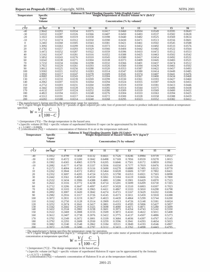
2001-25
Report on Proposals F2006 — Copyright, NFPA NFPA 2001 Halotron II Total Flooding Quantity Table (English Units)a
Temperature Specific Vapor
Volume
Weight Requirement of Hazard Volume W/V (lb/ft3)b
Concentration (% by volume)e
t s(°F)c (ft3/lb)d 8 9 10 11 12 13 14 15 16-40 2.9642 0.0293 0.0334 0.0375 0.0417 0.0460 0.0504 0.0549 0.0595 0.0643-30 3.0332 0.0287 0.0326 0.0366 0.0407 0.0450 0.0493 0.0537 0.0582 0.0628-20 3.1022 0.0280 0.0319 0.0358 0.0398 0.0440 0.0482 0.0525 0.0569 0.0614-10 3.1712 0.0274 0.0312 0.0350 0.0390 0.0430 0.0471 0.0513 0.0556 0.06010 3.2402 0.0268 0.0305 0.0343 0.0381 0.0421 0.0461 0.0502 0.0545 0.058810 3.3092 0.0263 0.0299 0.0336 0.0373 0.0412 0.0452 0.0492 0.0533 0.057620 3.3782 0.0257 0.0293 0.0329 0.0366 0.0404 0.0442 0.0482 0.0522 0.056430 3.4472 0.0252 0.0287 0.0322 0.0359 0.0396 0.0433 0.0472 0.0512 0.055340 3.5162 0.0247 0.0281 0.0316 0.0352 0.0388 0.0425 0.0463 0.0502 0.054250 3.5852 0.0243 0.0276 0.0310 0.0345 0.0380 0.0417 0.0454 0.0492 0.053160 3.6542 0.0238 0.0271 0.0304 0.0338 0.0373 0.0409 0.0445 0.0483 0.052170 3.7232 0.0234 0.0266 0.0298 0.0332 0.0366 0.0401 0.0437 0.0474 0.051280 3.7922 0.0229 0.0261 0.0293 0.0326 0.0360 0.0394 0.0429 0.0465 0.050290 3.8612 0.0225 0.0256 0.0288 0.0320 0.0353 0.0387 0.0422 0.0457 0.0493100 3.9302 0.0221 0.0252 0.0283 0.0314 0.0347 0.0380 0.0414 0.0449 0.0485110 3.9992 0.0217 0.0247 0.0278 0.0309 0.0341 0.0374 0.0407 0.0441 0.0476120 4.0682 0.0214 0.0243 0.0273 0.0304 0.0335 0.0367 0.0400 0.0434 0.0468130 4.1372 0.0210 0.0239 0.0269 0.0299 0.0330 0.0361 0.0393 0.0427 0.0460140 4.2062 0.0207 0.0235 0.0264 0.0294 0.0324 0.0355 0.0387 0.0420 0.0453150 4.2752 0.0203 0.0231 0.0260 0.0289 0.0319 0.0350 0.0381 0.0413 0.0446160 4.3442 0.0200 0.0228 0.0256 0.0285 0.0314 0.0344 0.0375 0.0406 0.0438170 4.4132 0.0197 0.0224 0.0252 0.0280 0.0309 0.0339 0.0369 0.0400 0.0432180 4.4822 0.0194 0.0221 0.0248 0.0276 0.0304 0.0333 0.0363 0.0394 0.0425190 4.5512 0.0191 0.0217 0.0244 0.0272 0.0300 0.0328 0.0358 0.0388 0.0419200 4.6202 0.0188 0.0214 0.0240 0.0268 0.0295 0.0323 0.0352 0.0382 0.0412
a The manufacturer’s listing specifies the temperature range for operation.b W/V [Agent Weight Requirement (lb/ft3)] = pounds of agent required per cubic foot of protected volume to produce indicated concentration at temperature specified.
c t [temperature (°F)] – The design temperature in the hazard area.d s [specific volume (ft3/lb)] = specific volume of superheated Halotron II vapor can be approximated by the formula: s = 3.2402 + 0.0069te C [concentration (%)] = volumetric concentration of Halotron II in air at the temperature indicated.
Halotron II Total Flooding Quantity Table (SI Units)a
Temperature Specific Vapor
Volume
Weight Requirement of Hazard Volume W/V (kg/m3)b
Concentration (% by volume)e
t s(°C)c (m3/kg)d 8 9 10 11 12 13 14 15 16
-40 0.1812 0.4799 0.5458 0.6132 0.6821 0.7526 0.8246 0.8984 0.9739 1.0512-30 0.1902 0.4572 0.5200 0.5842 0.6498 0.7169 0.7856 0.8559 0.9278 1.0015-20 0.1992 0.4365 0.4965 0.5578 0.6205 0.6846 0.7501 0.8172 0.8859 0.9562-10 0.2082 0.4177 0.4750 0.5337 0.5936 0.6550 0.7177 0.7819 0.8476 0.91490 0.2172 0.4004 0.4553 0.5116 0.5690 0.6278 0.6880 0.7495 0.8125 0.877010 0.2262 0.3844 0.4372 0.4912 0.5464 0.6028 0.6606 0.7197 0.7802 0.842120 0.2352 0.3697 0.4205 0.4724 0.5255 0.5798 0.6353 0.6921 0.7503 0.809830 0.2442 0.3561 0.4050 0.4550 0.5061 0.5584 0.6119 0.6666 0.7226 0.780040 0.2532 0.3434 0.3906 0.4388 0.4881 0.5386 0.5901 0.6429 0.6970 0.752350 0.2622 0.3316 0.3772 0.4238 0.4714 0.5201 0.5699 0.6209 0.6730 0.726560 0.2712 0.3206 0.3647 0.4097 0.4557 0.5028 0.5510 0.6003 0.6507 0.702370 0.2802 0.3103 0.3530 0.3965 0.4411 0.4867 0.5333 0.5810 0.6298 0.679880 0.2892 0.3007 0.3420 0.3842 0.4274 0.4715 0.5167 0.5629 0.6102 0.658690 0.2982 0.2916 0.3317 0.3726 0.4145 0.4573 0.5011 0.5459 0.5918 0.6388100 0.3072 0.2831 0.3219 0.3617 0.4023 0.4439 0.4864 0.5299 0.5744 0.6200110 0.3162 0.2750 0.3128 0.3514 0.3909 0.4313 0.4726 0.5148 0.5581 0.6024120 0.3252 0.2674 0.3041 0.3417 0.3801 0.4193 0.4595 0.5006 0.5427 0.5857130 0.3342 0.2602 0.2959 0.3325 0.3698 0.4080 0.4471 0.4871 0.5280 0.5699140 0.3432 0.2534 0.2882 0.3238 0.3601 0.3973 0.4354 0.4743 0.5142 0.5550150 0.3522 0.2469 0.2808 0.3155 0.3509 0.3872 0.4243 0.4622 0.5011 0.5408160 0.3612 0.2407 0.2738 0.3076 0.3422 0.3775 0.4137 0.4507 0.4886 0.5273170 0.3702 0.2349 0.2672 0.3001 0.3339 0.3684 0.4036 0.4397 0.4767 0.5145180 0.3792 0.2293 0.2608 0.2930 0.3259 0.3596 0.3941 0.4293 0.4654 0.5023190 0.3882 0.2240 0.2548 0.2862 0.3184 03513 0.3849 0.4193 0.4546 0.4907200 0.3972 0.2189 0.2490 0.2797 0.3112 0.3433 0.3762 0.4098 0.4443 0.4795
a The manufacturer’s listing specifies the temperature range for operation.b W/V [Agent Weight Requirement (kg/m3)] = kilograms of agent required per cubic meter of protected volume to produce indicated concentration at temperature specified.
c t [temperature (°C)] – The design temperature in the hazard area.d s [specific volume (m3/kg)] = specific volume of superheated Halotron II vapor can be approximated by the formula: s = 0.2172 + 0.0009te C [concentration (%)] = volumetric concentration of Halotron II in air at the temperature indicated.
W Vs
CC
=−
100
W Vs
CC
=−
100

2001-26
Report on Proposals F2006 — Copyright, NFPA NFPA 2001 ________________________________________________________________ 2001-85 Log #79 Final Action: Accept (Table A.5.6(j)) ________________________________________________________________ Submitter: Richard L. Niemann, Modular Protection Corp. Recommendation: Revise table adding new data for extinguisher of Class C energized electrical hazards and renumber.
Substantiation: Provides test data for use as guidance for the fire protection engineer in designing clean agent systems for hazards involving Class C energized fires, such as those that exist in telecommunications facilities or data centers. Committee Meeting Action: Accept ________________________________________________________________ 2001-86 Log #4 Final Action: Accept (Annex B) ________________________________________________________________ Submitter: Joseph A. Senecal, Kidde-Fenwal, Inc. Recommendation: Replace existing Annex B “Cup Burner Test Method” with a revised “Cup Burner Test Method” NFPA Task Group on the Cup-burner Test Method Draft Document, Rev 2Issued May 10, 2005 for consideration ofGFE-AAA Committee on Gaseous Fire Extinguishing Systems Title. Cup-burner method for determining the minimum concentration of gaseous agent for flame extinguishmentIntroduction. Total flooding fire extinguishing systems are widely used for protection of enclosures where flammable materials, including liquids and gases, are processed or stored1. The fire extinguishing agent used in such a system may be a gas or a liquid under storage conditions. When released into the atmosphere of the protected space the agent disperses, and evaporates if initially a liquid, to form a mixture of air and gaseous agent. Successful fire suppression occurs when the agent concentration exceeds the minimum extinguishing concentration (MEC) by a sufficient margin, or safety margin, to cause rapid flame extinguishment. Use of excessive amounts of agent may be undesirable for reasons related to total system cost or, often more importantly, due to the need to avoid creating an agent-air atmosphere that is itself harmful to people due to considerations of hypoxia, agent toxicity, or both. In the case of flammable liquid hazards the minimum design concentration (MDC) of a gaseous agent is specified in national and international standards as the MEC times a safety factor. This test method uses the cup-burner to determine, for a
given fuel, the MEC of a gaseous agent. The cup-burner method is inherently empirical. The theoretical and parametric aspects of flame extinguishment in this procedure have been addressed by many authors and is the subject of ongoing research. A few recent references are given below.�, �, � 1 Scope1.1 This test method provides a standard measure of minimum flame extinguishing concentration of a gaseous extinguishing agent for flames of flammable or combustible liquids and flammable gases.5
1.2 This method has value as a means of meeting the requirements of national and international standards for determination of the minimum design concentration of a gaseous agent.1.3 This method is applicable to gaseous fire extinguishing agents that can be introduced into the test apparatus as a gas that is uniformly mixed in air. 1.4 This test method is applicable to liquid fuels that have adequate fluidity at the test temperature to allow accurate liquid level control in the cup. The method may be difficult to use with very viscous fuels.1.5 This method is applicable to fuels that are ignitable at the operating temperature of the cup. 1.6 The values stated in SI units are to be regarded as the standard. The values given in parentheses are for information only. 1.7 This test method does not purport to address all of the safety concerns, if any, associated with its use. It is the responsibility of the user of this test method to establish appropriate safety and health practices and determine the applicability of regulatory limitations prior to use. For specific hazard statements, see Section 7. 2 Referenced documents. 2.1 ASTM E 176 Terminology of Fire Standards. 2.2 ASTM E 177 Standard Practice for Use of the Terms Precision and Bias in ASTM Test Methods2.3 ASTM E 456 Standard Terminology for Relating to Quality and Statistics2.4 ASTM E 691 Standard Practice for Conducting an Interlaboratory Study to Determine the Precision of a Test Method 2.5 NFPA 2001 Standard for Clean Agent Fire extinguishing Systems, National Fire Protection Association, Quincy, MA (2004).2.6 ISO 14520 Gaseous fire-extinguishing systems —Physical properties and system design —Part 1: General requirements (2000).2.7 UL-2166 Standard for Halocarbon Clean Agent Extinguishing System Units (31 March 1999).2.8 UL-2127 Standard for Inert Gas Clean Agent Extinguishing System Units (31 March 1999).3 Terminology.3.1 Definitions. For definitions used in this test method refer to NFPA 2001 and ASTM E 176. 3.2 Definitions of terms specific to this standard.3.2.1 Agent. Fire extinguishing gas which when added to air in sufficient quantity causes extinguishment of the test flame. Agents consisting of non-condensable gases, vapors of liquefied compressed gases, and vapors of volatile liquids are in commercial use.3.2.1.1 Primary reference agent. Nitrogen. Minimum purity 99.9%.3.2.1.2 Secondary reference agent. Agent more nearly similar to the study agent in extinguishing concentration for the reference fuel than nitrogen.6
3.2.1.3 Study agent. Agent which is the subject of study in the cup-burner.3.2.2 Cup. Fuel reservoir and flame stabilizer.3.2.3 Chimney. Transparent tube, usually glass, that contains the cup and confines air and agent flow.3.2.4 Flow straightener. Mechanical means of establishing non-turbulent uniform vertical flow at the base of the chimney.3.2.5 Extinguishing concentration. The concentration of agent in air that causes extinguishment of the test flame within the observation period. 3.2.6 Extinguishment. Cessation of combustion above the cup.3.2.7 Fuel. Flammable or combustible liquid or flammable gas supplied to the cup. 3.2.7.1 Reference fuel. 3.2.7.1.1 Liquid reference fuel: n-Heptane. Minimum purity 99%.3.2.7.1.2 Gaseous reference fuel: Methane7. Minimum purity 99%.3.2.7.2 Study fuel. Fuel for which an extinguishing concentration of an agent is to be determined. 3.2.8 Lifted flame. Flame for which the base becomes lifted above cup rim by at least 10 mm at any non-extinguishing agent concentration. The occurrence of lifted flames should be noted in test report. 3.2.9 Minimum extinguishing concentration - MEC. The lowest value of extinguishing concentration determined by this method. 3.2.10 Observation period. A period of at least 10 s after change in agent flow rate. 3.2.11 Pre-burn time. Period between ignition of fuel and start of agent flow. The pre-burn time should be 95 ± 5 s.8 4 Summary of Test Method
Table A.5.6(fj) Test Results
Agent
EnergyLevel(W)
Extinguish(Minimum
Concentration,Percent by
Volume)
PreventReflash/Reignition
(MinimumConcentration,
Percent by Volume)
FC-3-1-10 48192
5.56.5
8.09.5
FK-5-1-12 48192
4.14.5
4.55.1
HFC-125 48192
11.511.9
12.012.4
HFC-23 48192
13.014.0
16.020.0
HFC-227ea 48192
6.58.0
8.09.0
HFC-236fa 48192
6.36.5
6.5 8.79.0
IG-541 48192
41.849.0
49.056.1
References:1. Niemann, R., Bayless, H., and Craft, C., “Evaluation of Selected NFPA 2001 Agents for Suppressing Class “C” Energized Fires.” Proceedings, Halon Options Technical Working Conference, Albuquerque, NM, pp. 399-412, 1996.2. Driscoll, M., Rivers, P., 3M, “Clean Extinguishing Agents and Continuously Energized Circuits: Recent Findings, “Proceedings, Halon Options Technical Working Conference, Albuquerque, NM, pp. 129-140, 1997.3. Bayless, H., and Niemann, R., “Update on the Evaluation of Selected NFPA 2001 Agents for Suppressing Class “C” Energized Fires” Proceedings, Halon Options Technical Working Conference, Albuquerque, NM, pp. 293-294, 1998.4. Bengtson, G., Niemann, R., “Update in the Evaluation of Selected NFPA 2001 Agents for Suppressing Class C Energized Fires”, Proceedings, Halon Options Technical Working Conference, Albuquerque, NM, May 24-26, 2005.

2001-27
Report on Proposals F2006 — Copyright, NFPA NFPA 2001 4.1 Air is delivered to the base of the chimney. The measurements necessary for determining the air flow rate are recorded. 4.2 The air stream passes through a flow straightener to establish uniformly distributed flow and reduce turbulence.4.3 A flame of the test fuel is established at the cup. For a liquid fuel the liquid level in the cup is maintained within prescribe limits. The flow rate of a gaseous fuel is kept at a fixed value.4.4 The flame is allowed to burn in air for a prescribed period of time, the pre-burn time.4.5 Agent is added to the air stream in steps. The measurements necessary for determining the agent flow rate, agent concentration in air, or other relevant data are recorded as appropriate to the specific method of agent flow control. 4.6 After each change in agent flow rate the effect of the agent-air mixture on the flame is observed. If the flame is extinguished during the observation period the result is recorded as an extinguishing condition and the determination is concluded. Otherwise, then the agent flow rate is increased.4.7 The extinguishing concentration for each determination are calculated or otherwise determined from the data. 4.8 At last five determinations of extinguishing concentration are made exclusive of initial trials conducted for the purpose of determining the approximate extinguishing point. 4.9 The results of the several determinations of extinguishing concentration are analyzed statistically and reported. 5 Significance and Use5.1 This test method provides a means to determine the MEC in air of a gaseous agent to extinguish flames of a liquid and gaseous fuels.5.2 An MEC value determined by this method is specific to the apparatus and procedure employed herein. The minimum concentration of agent in air necessary to extinguish combustion of the same fuel under other laboratory or field conditions may be different than determined by this method.5.3 The MEC determined by this method may be used as a basis of determining minimum agent design concentration for a total flooding application in accordance with the requirements of relevant standards for total flooding fire extinguishing systems. In particular, this method meets the requirements of NFPA 2001 for determining the MEC of an agent for a Class B liquid fuel.6 Interferences6.1 Fuel character. Some fuels may change character in the cup during the test as a consequence of distillation, chemical reaction, precipitation of solids, or by other means. In such cases the extinguishing concentration determined by this method may not accurately reflect the fuel in its most difficult to extinguish form. 6.2 Air. Some laboratories may employ compressed “air” supplied in cylinders by a commercial source. In such instances the “air” must be certified as compressed atmospheric air. Some commercially supplied “air” is prepared by blending previously separated oxygen and nitrogen. The oxygen concentration in such mixtures may deviate significantly from 20.95 mol %, the sea level composition of dry air. Deviation of oxygen concentration from the standard value in supplied “air” will have an effect on the measured extinguishing concentration of the agent. Additionally, the argon content of prepared “air” may deviate from the 0.93 mol % sea level value. Argon has a significantly lower thermal conductivity than nitrogen and, as such, argon excess or deficiency could have a measurable effect on the apparent extinguishing of an agent. 6.3 Barometric pressure.9
6.4 Deposits on cup rim. Deposits can cause the liquid fuel to wick down the outside of the cup, making the flame burn from the outside of the cup as well as from the inside.6.5 Humidity. Water vapor is an inert gas fire extinguishing agent. The temperature and relative humidity of air supplied to the chimney should be measured and recorded. See footnote below on R.H. effect.6.6 Fuel overflow. Fuel overflow from cup into chimney base invalidates test.7 Safety Precautions7.1 Pressurized equipment. Extinguishing agents may be supplied in pressurized cylinders. Caution must be exercised securing pressurized cylinders, tubing, valves and fittings. 7.2 Combustion product ventilation. Combustion products are, in general, hazardous. They may contain carbon monoxide, soot and partial combustion products the toxicity of which depends on the fuel chemistry. When halogenated extinguishing agents are tested combustion will produce halogen acids, such as HF, HCl, HBr and HI, and carbonyl compounds such as COF2 and COCl2. . An adequate means of ventilation should be employed to exhaust combustion products, away from the work space. 7.3 General fire hazard. There is an attendant general flammable liquids fire hazard associated with conducting cup-burner tests. Test technicians should understand this hazard and be trained to respond appropriately in the event of a fuel spill or uncontrolled fuel ignition.8 Apparatus8.1 Cup-burner apparatus. The basic cup-burner apparatus consists of the following elements: base assembly, chimney, cup, and flow straightener and is shown schematically in figure 1.10
8.1.1 Base assembly. The base assembly securely supports the chimney, cup and flow straightener. The base assembly has provisions
8.1.1.1 to admit air and agent to a plenum below the flow straightener8.1.1.2 to admit fuel to the cup liquid connection8.1.1.3 for electrical connections or other means of cup heating8.1.1.4 for thermocouples or other temperature measuring means8.1.2 Chimney. The chimney consists of a standard 90 ±1.3 mm O.D. glass tube with 2.4 ±0.3 mm wall thickness suitable for high temperature use11. The overall chimney tube length is sufficient to accommodate the following minimum dimensions: 8.1.2.1 Flow straightener to cup rim: 250 mm (nominal) 8.1.2.2 Cup rim to top of chimney: 300 mm (nominal)8.1.3 Fuel supply. 8.1.3.1 Liquid fuel reservoir. Liquid fuel should be supplied from a reservoir that permits adjustment of the liquid fuel height in the cup. In one method fuel is supplied by gravity flow from a reservoir mounted on a means of adjusting its height, such as on a laboratory jack stand. The fuel reservoir should be several times larger in diameter than the cup to minimize change in the fuel liquid level during a test. Several methods are available for maintaining a constant reservoir liquid level. 8.1.3.2 Gaseous fuel supply. 8.1.4 Cup. 8.1.4.1 Body. The cup should be made of quartz or other glass suitable for high temperature use. The nominal dimensions of the cup at the top are: OD = 31 mm; ID = 21.5 mm. The cup rim have a 45 degree internal chamfer fully crossing the glass annulus. The dimensional details and shape of the upper portion of the cup should be as shown in Fig. 2.12
8.1.5 Cup preparation for gaseous fuels. When gaseous fuels are used it is necessary to place packing material or screening in the cup in such manner as to facilitate uniform fuel gas flow across the exit face of the cup. There is discretion on how this is achieved.13
8.1.5.1 Heating element. A means of heating liquid fuel in the cup may be incorporated by any method that does not cause localized boiling of liquid fuel on the heating surface. Methods found suitable include use of a heating element immersed in the fuel (fully below liquid surface) or use of a heating element contained within the glass wall of the cup. 8.1.5.2 Temperature measurement. A means of measuring fuel temperature prior to ignition is required. An in situ thermocouple (below liquid surface) for fuel temperature measurement during a test may prove convenient.8.1.6 Flow straightener. The flow straightener is a means of assuring uniform non-turbulent upward air velocity at the base of the chimney. A suitable flow straightener may employ a bed of glass bead above the air inlet plenum or other flow straightening materials. 8.2 Gas flow rates and agent concentration measurement. 8.2.1 Air supply. 8.2.1.1 Flow rate. Measurement of air flow rate may be made with any of several type of flow meters including rotameters, mass flow meters, bubble flow meters. 8.2.1.2 Humidity. Air supplied to the cup-burner should be dry.14 8.2.2 Agent. 8.2.2.1 Gaseous agent. Measurement of gas or vapor flow rate may be made with any of several type of flow meters including rotameters, mass flow meters, bubble flow meters. 8.2.2.2 Liquid agent. The method employed to deliver and vaporize an agent that is a liquid at ambient conditions should be reported. 8.2.2.3 Agent concentration. Direct measurement of agent concentration in the agent-air stream is measured using any of several possible methods including, but not limited to, 8.2.2.3.1 gas chromatographic, infrared absorption, or other type of analysis of discreet air-agent samples 8.2.2.3.2 continuous sampling and measurement by detector based on thermal conductivity, infrared absorption, or other measuring principle.8.2.2.4 Oxygen concentration. Agent concentration can, in some instances, be inferred with sufficient accuracy from determination of the oxygen concentration in the agent-air mixture. Oxygen concentration in gases is commonly measured using methods based on paramagnetic or electrochemical sensors. Interference effects, if any, of agent gas on oxygen concentration measurement must be determined and accounted for.8.3 Gaseous fuel. Measurement of gaseous fuel flow rate may be made with any of several type of flow meters including rotameters, mass flow meters, bubble flow meters, or other means. 9 Calibration and Standardization9.1 Measuring equipment should be calibrated on a regular basis and any time when test conditions indicate that re-calibration is necessary.9.2 The measurement uncertainty or precision of measuring equipment should be determined and recorded.9.3 The vertical alignment of the chimney should be verified periodically. A spirit level should suffice for this purpose.9.4 The cup should be aligned vertically and be concentric with the axis of the chimney. 9.5 Flow regulating valves, where used, should be sized for the anticipated flow rate and should not leak at the pressurized connections.
2001-28
Report on Proposals F2006 — Copyright, NFPA NFPA 2001 9.6 System calibration. System calibration tests should be conducted using n-heptane (reference fuel) and at least two reference agents.9.6.1 Primary reference agent. Nitrogen should be employed as the primary reference agent. 9.6.2 Second reference agent. The second reference agent should be selected from among those for which consensus data is available which has extinguishing performance nearer to the study agent. 9.6.3 Calibration interval. The interval between system calibrations should be short enough to assure that measurable changes in results are detected and causes identified and corrected. 9.7 Standardization. 9.7.1 Evaluation of a study fuel with a reference agent should include a standardization test using a reference fuel with the reference agent.9.7.2 Evaluation of a study agent with a reference fuel should include a standardization test using a reference agent with a reference fuel. 9.7.3 Evaluation of a study agent with a study fuel should include two standardization tests 9.7.3.1 Reference agent test using a reference agent with the study fuel.9.7.3.2 Reference fuel test using study agent with a reference fuel. 10 Test Specimens 10.1 Air. “Air” should be supplied as compressed natural air either filtered (for oil mist, particulate matter, and moisture condensate) from a local compressor drawing in fresh ambient air or from high pressure cylinders of certified compressed air. “Air” prepared by re-mixing previously separated oxygen and nitrogen should not be used. 10.2 Fuel. The fuel should be of a certified type and purity. 10.3 Agent. The agent should be of a certified type and purity or composition.11 Conditioning11.1 Temperature, laboratory. Tests should be conducted at ambient laboratory temperature, nominally in the range of 20 to 25°C. 11.2 Temperature, fuel. Fuel in the cup should be brought to a temperature of 20 to 25 °C or 5±1 °C above its open cup flash point, which ever is higher. 11.3 Barometric pressure should be measured and recorded. 12 Procedure12.1 Liquid fuels12.1.1 Establish air flow in chimney at 40±2 L/min at laboratory ambient conditions.15
12.1.2 Admit liquid fuel to cup bringing liquid level to about 5 to 10 mm below cup rim.12.1.3 Adjust temperature of fuel as required by 11.2. 12.1.4 Ignite the fuel. 12.1.5 Begin the measurement of pre-burn time. 12.1.6 At the start of the pre-burn period the liquid level of the fuel is raised to within 1 mm of the cup rim or as close to the rim as is practicable without overflowing the cup. The fuel liquid level is to be maintained at this position during the test. 12.1.7 At the end of the pre-burn time begin agent addition.12.1.8 Agent addition.12.1.8.1 Agent is added to the air flow in steps. After each change in agent flow rate the flame is observed for a period long enough to make measurements, but at least 10 s, before increasing the agent flow rate. 12.1.8.2 Begin addition of agent to the air stream. Where the extinguishing point is known approximately, the initial agent flow rate can be brought to about 80% of that value. Subsequent increases in agent flow rate should be no more than 2% and should be smaller at the extinguishing point is approached. The agent flow rate, or other characteristic measure of agent concentration, should be recorded at each adjustment of agent flow at the extinguishing point is approached. It is a matter of experience and judgement as to how small agent flow adjustments should be at any point during the test and when to record such pre-extinguishment data.12.1.8.3 If the flame is not extinguished during the 10 s observation period then the agent flow rate is increased. This step is repeated until flame extinguishment occurs. 12.1.8.4 The agent flow rate at extinguishment is recorded.16
12.1.9 The temperature of the fuel at the time of extinguishment may be measured and recorded. This is supplementary information which may be helpful in analysis of results in some cases. 12.1.10 At the conclusion of each test the fuel liquid level should be lowered several mm. A pipette should be employed to remove at least 10 mL of liquid fuel from the top of cup to remove decomposition products of both the fuel and agent and, where the fuel is a mixture, to remove fuel concentrated in species of higher boiling point due to preferential evaporation of lighter species at surface.12.1.11 Number of test trials. A determination of extinguishing concentration should be based on results from at least five (5) test trials in sequence exclusive of initial trials conducted for the purpose of determining the approximate extinguishing point. 12.2 Gaseous fuels12.2.1 Establish air flow in chimney to achieve a nominal air velocity at the cup-chimney annulus of 13.6±0.7 cm/s ( volumetric air flow rate of ~ 40±2 L/min in an 85 mm ID chimney with a cup diameter of 31 mm) at laboratory conditions (pressure and temperature).
12.2.2 Measure and record air temperature and humidity. 12.2.3 Admit gaseous fuel to cup and ignite. 12.2.4 Fuel flow rate & flame size. Adjust the fuel gas flow rate to achieve a visible flame height of about 75 – 85 mm.17 12.2.5 Begin the measurement of pre-burn time. 12.2.6 At the end of the pre-burn time begin agent addition.12.2.7 Agent addition. 12.2.7.1 Agent is added to the air flow in steps. After each change in agent flow rate the flame is observed for a period long enough to make measurements, but at least 10 s,before increasing the agent flow rate. 12.2.7.2 Begin addition of agent to the air stream. Where the extinguishing point is known approximately, the initial agent flow rate can be brought to about 80% of that value. Subsequent increases in agent flow rate should be no more than 2%. The agent flow rate, or other characteristic measure of agent concentration, should be recorded at each adjustment of agent flow at the extinguishing point is approached. It is a matter of experience and judgement as to how small agent flow adjustments should be at any point during the test and when to record such pre-extinguishment data.12.2.7.3 If the flame is not extinguished during the 10 s observation period then the agent flow rate is increased. This step is repeated until flame extinguishment occurs. 12.2.7.4 The agent flow rate at extinguishment is recorded. See foot 16.12.2.8 At the conclusion of each test the cup rim should be checked for deposits (soot) and cleaned if required.12.2.9 Number of test trials. A determination of extinguishing concentration should be based on results from at least five (5) test trials, exclusive of preliminary ranging trials, in sequence. 13 Agent concentration 13.1 General. The concentration of interest is that of the agent gas in the agent-air mixture. Concentration is often expressed as “volume per cent” but this is not strictly correct as “concentration” is actually a measure of quantity of substance per unit volume, e.g., mol/Liter or g/L. Volume per cent is a measure of the volume fraction of an air-agent mixture that consists of agent gas. This measure is convenient in practice and is not discouraged as long as it is determined correctly. Caution is required in cases where the density of agent vapor, either pure or diluted in air, departs measurably from that of an ideal gas of the same molecular weight. It is recommended that concentration be calculated as mole fraction or mole percent. The supplier of each agent can guide their users as to conversion to volume percent for use in fire extinguishing system design.13.2 Flow rate methods. 13.2.1 Volumetric flow rate. Volumetric flow rate air or agent, measured using calibrated flow meters, should be converted to molar flow rate by multiplying by the gas density and dividing by the agent mean molecular weight. To determine the density of some agents gases it may be necessary to consult the physical property data (table or equation of state) supplied by the manufacturer.13.2.2 Mass flow rate. Where a calibrated mass flow rate measuring device is used convert the mass flow rate to molar flow rate by dividing by the molecular weight.N = Molar flow rate = mass flow rate / molecular weight13.2.3 Calculate mole fraction, XG, of agent in the agent-air mixture.
13.2.4 Calculate agent concentration in mole percent as
13.3 Direct gas analysis method. Any of several types of gas analyzers may be calibrated with prepared agent-air mixtures of known composition. 13.3.1 Continuous sampling analyzer. If the analyzer is of the continuous sampling type the gas analyzer may then be used to measure the agent concentration in sample of air-agent mixture drawn from the flowing stream during the test and in particular at the times just before and just after flame extinguishment.13.3.2 Discreet sample analyzer. Agent concentration can be determined by analyzing a sample of the agent-air mixture in a gas chromatograph or other calibrated gas analyzer.13.4 Oxygen analyzer measurement method. The concentration of agent in an agent-air mixture can be calculated from a measurement of oxygen concentration in the mixture. Dry atmospheric air consists of 20.95 mol % oxygen18. The concentration of a diluting ideal gas (agent) is given by
Where the source “air” is not atmospheric air the actual oxygen concentration of the source “air” (in volume or mole %) should be substituted for the value 20.95 in the above relation. It should be verified that the agent gas does not have an interference effect oxygen analyzer response.
X NN NG
G
G Air
=+
Mole Agent XG% _ =100
% %.
Agent O= −
⋅1
20 951002

2001-29
Report on Proposals F2006 — Copyright, NFPA NFPA 2001 13.5 Statistics. The results of the separate determinations of extinguishing concentration should be used to determine average and standard deviation14 Test Report14.1 The test report should contain the following information:14.1.1 Apparatus description.14.1.2 Summary of test procedure and exceptions14.1.3 Date of report14.1.4 Fuel name and grade.14.1.5 Agent type and composition14.1.6 Test conditions including14.1.6.1 Barometric pressure14.1.6.2 Laboratory temperature, or temperature of air entering base of chimney if different from laboratory temperature14.1.6.3 Humidity of air supplied to chimney.14.1.7 Air flow rate at test conditions14.1.8 Fuel temperature 14.1.8.1 Measure and record fuel temperature prior to ignition.14.1.8.2 Measure and record fuel temperature at flame extinction.14.1.9 Agent flow rate at test conditions, if measured.14.1.10 Gas analyzer measurements, if used.14.1.11 Sample calculation of agent concentration14.1.12 Summary table of results including:14.1.12.1 Data for each combination of agent and fuel tested including:14.1.12.1.1 Calibration tests14.1.12.1.2 Standardization tests14.1.12.1.3 Study tests14.1.12.2 Sample statistics including14.1.12.3 Number of measurements, n14.1.12.4 Average extinguishing concentration,
14.1.12.5 Standard deviation,
14.1.13 Comparison of study results with standardization 14.1.14 Notes on exceptions in the apparatus, procedure, and analysis.15 Precision and Bias15.1 Precision. 15.1.1 Repeatability. The repeatability should be calculated as follows. [To be developed]15.1.2 Reproducibility. [To be developed]15.2 Bias. [To be developed]16 Keywords 16.1 cup-burner, extinguishing concentration, gaseous agent17 Figures (Figure 1 to be revised to reflect dimensions and tolerances in Section 8 of text). [revise figure for simplified apparatus w/o heating coil. Design needs to be agreed.] The large majority of total flooding fire extinguishing systems are used for protection of Class A fire hazards such as data centers, clean rooms, telephone central offices, control rooms, etc. These occupancies do not normally contain Class B fire hazards. 2 Preece, Stephen, Paul Mackay and Adam Chattaway, The Cup Burner Method – A Parametric Analysis of the Factors Influencing the Reported Extinguishing Concentrations of Inert Gases, Proceedings of the Halon Options Technical Working Conference, April 24-26, 2001, Albuquerque, NM, May 13-15, 2003. 3 Senecal, Joseph A., Flame Extinguishing by Inert Gases: Theoretical & Experimental Analysis, Proceedings of the 2004 Technical Meeting of the Central States Section of the Combustion Institute, Austin, TX, March 21-22, 2004.4 Takahashi, Fumiaki, Gregory T. Linteris, and Viswanath R. Katta, Suppression of Cup-Burner Flames, Fourth International Symposium on Scale Modeling (ISSM-IV), Cleveland, OH, September 17-19, 2003.5 Flames of gaseous fuels behave differently than liquids in this test. Gaseous fuel flow is fixed at the start of the test. Liquid fuel vapor flow decreases as the extinguishing point is approached due to reduction in heat transfer rate. Also see Linteris, G.T., Suppression of Cup-Burner Flames by Super-Effective Chemical Inhibitors and Inert Compounds, Proceedings of the Halon Options Technical Working Conference, April 24-26, 2001, Albuquerque, NM, pp. 187-196. Figures 1 and 2 illustrate the relationship of liquid fuel consumption rate and agent concentration. 6 CO2 might serve well as a secondary reference agent as it is readily available and has an extinguishing concentration ~2/3 that of nitrogen thereby establishing a significant span useful in establishing bench mark performance.7 Fumiaki Takahashi commented: Methane, a main ingredient of natural gas, is favorable because its reaction mechanism is most known and thus most widely used in combustion research. Accurate numerical predictions can be made with full chemistry. However, as Irv Glassman has frequently mentioned, methane (C1) is unique kinetically compared to higher hydrocarbons. Ethane (C2) represents kinetics of higher hydrocarbons more
closely as they decompose to smaller HCs and the oxidation reaction pathway is ethane to ethylene then to acetylene. When I was in Dayton (UDRI, on-site at WPAFB), Sandia, NM, specifically requested us to use ethane as the fuel for the extinguishing nitrogen concentration measurement in step-stabilized flames. Propane is another popular fuel and attractive for research use, although it (C3) is also somewhat unique kinetically. Therefore, methane and propane may be practically reasonable, but ethane may be more scientifically sound. 8 July 8, 20048 Note. NFPA 2001 (2004 ed., Annex B) specification is “90 to 120 s” for liquids and 60 s for gases. At the recommendation of the VdS representative, ISO TC 21/SC 8 opted in September 2003 for a
10060 +
− s pre-burn time for liquid fuels and 60 s with no tolerance, for gaseous fuels. 9 Note. It has yet to be demonstrated whether barometric pressure variation from 101.3 Pa affects results obtained in this test. A controlled experimental effort is required.10 Simplified apparatus w/o heater recommended by FK and MLR. Dimensioned cross sectional drawing needed.11 The specified chimney dimensions are standard and available in Pyrex and Kimax brand tube.12 Note. The cup diameters given are from the ICI design which employs a two-layer design that allows a platinum heating wire to be wrapped around the cup. The OD of the cup is deemed more important than the ID. The liquid pool diameter just below the chamfer is about 25 to 27 mm. 13 Takahashi et al (2003) filled the cup with 3 mm glass beads and placed two layers of 40 mesh screen on top. 14 A systematic study by Kidde plc showed that for one halocarbon agent the extinguishing concentration was linearly related to the humidity of the supplied air. The MEC for 100% R.H. air (~21 C) was ~11% (relative) less than that determined for ~0% R.H. air. Reference P. Mackay memorandum, 18 May 2004. In addition, analysis (July 2004 by J.A. Senecal) of humidity effects on inert gas (nitrogen) extinguishment indicates that feasible variations in humidity of air supplied to the cup-burner can affect the extinguishing concentration, XG. Specifically, it is estimated that in the two extremes of (a) dry air and (b) 70% R.H. air at 25°C the variation in XG is approximately 0.313 < XG < 0.295, or 6% which is at least twice the estimated uncertainty of the measurement. An R.H. correction to results may be necessary.15 (a) The air flow rate should be 40±2 L/min which, for the standard chimney and cup configuration specified herein, corresponds to a superficial linear velocity in the cup-chimney annulus of 13.5 ± 0.7 cm/s. The air flow rate should be adjusted in consideration of the actual chimney and cup dimensions to achieve the same nominal annular air velocity. (b) The literature has discussed a “plateau” region in the air flow rate, i.e. a range of air velocities over which the MEC value is invariant, or nearly so. Most investigators report that the “plateau for halocarbon agents is usually at or near 40 L/min. It is also reported that there is no plateau for inert gas agents and the MEC value creeps up with increasing air velocity.16 The goal is to determine that agent concentration in at the extinguishing point. Methods that do not use direct measurement of agent flow rate are permitted. For example, composition analysis of agent-air mixture is acceptable.17 Takahashi et al (2003) studied a methane flame. They used an air flow velocity of 10.7 cm/s (volumetric rate of ~36 L/min) and a methane cup-exit velocity of 0.92 cm/s (flow rate ~0.34 L/min). This corresponds to an overall equivalence ratio of about 0.090, i.e., about 900% excess air for complete combustion. The uninhibited flame height was ~ 75 mm.18 See Handbook of Chemistry and Physics, 83rd ed., David R. Lide, editor, Ch. 14, p.19 “U.S. Standard Atmosphere (1976)”, CRC Press LLC (2002). 19 The large majority of total flooding fire extinguishing systems are used for protection of Class A fire hazards such as data centers, clean rooms, telephone central offices, control rooms, etc. These occupancies do not normally contain Class B fire hazards. 20 Preece, Stephen, Paul Mackay and Adam Chattaway, The Cup Burner Method – A Parametric Analysis of the Factors Influencing the Reported Extinguishing Concentrations of Inert Gases, Proceedings of the Halon Options Technical Working Conference, April 24-26, 2001, Albuquerque, NM, May 13-15, 2003. Senecal, Joseph A., Flame Extinguishing by Inert Gases: Theoretical & Experimental Analysis, Proceedings of the 2004 Technical Meeting of the Central States Section of the Combustion Institute, Austin, TX, March 21-22, 2004.21 Takahashi, Fumiaki, Gregory T. Linteris, and Viswanath R. Katta, Suppression of Cup-Burner Flames, Fourth International Symposium on Scale Modeling (ISSM-IV), Cleveland, OH, September 17-19, 2003.22 Flames of gaseous fuels behave differently than liquids in this test. Gaseous fuel flow is fixed at the start of the test. Liquid fuel vapor flow decreases as the extinguishing point is approached due to reduction in heat transfer rate. Also see Linteris, G.T., Suppression of Cup-Burner Flames by Super-Effective Chemical Inhibitors and Inert Compounds, Proceedings of the Halon Options Technical Working Conference, April 24-26, 2001, Albuquerque, NM, pp. 187-196. Figures 1 and 2 illustrate the relationship of liquid fuel consumption rate and agent concentration. 23 CO2 might serve well as a secondary reference agent as it is readily available and has an extinguishing concentration ~2/3 that of nitrogen thereby establishing a significant span useful in establishing bench mark performance.Figure 1. Cup-burner apparatus.See Figure 1 on the next pageFigure 2. Details of cup design. From ICI. See Figure 2 on the next page
xn
xi
n
= ∑11
s x x ni
n
= − −∑ ( ) ( )2
11

2001-30
Report on Proposals F2006 — Copyright, NFPA NFPA 2001
Agent/air mixture
250 mm
To gas analyzer
300 mm
90 mm
31 mm
Fuel level
CUP DETAILScale: none
31 mm O.D.(1 mm wall)
21.5 mm I.D.(1 mm wall)
S13joint
37 mm
252 mm
25 mm
70 mm
AB
C
D
E
Small glass tube (at 90° to plane of loops) to be sealed off after leads, etc., are fixed in place.
Inner tube8.5 mm O.D.7 mm I.D.
Outer tube12 mm O.D.10 mm I.D.
3 glass spacers (at 120° 25 mm from top rim)
Rim, ground to knife edge (as near as possible)
Double-start spiral groove etched in glass. Both spirals end on top capstan(A). One, 7 turns spaced ¹⁄₁₀ in. apart, starts at capstan B; the other, 7¹⁄₄ turns spaced ¹⁄₁₀ in. apart, starts at capstan C.
3 glass spacers (at 120°)
Tube for thermocouple 3 mm O.D., 1.5 mm I.D. (end of tube 2 mm below rim)
Platinum wire loops. (This wire, thicker than that of the coil, is carried up to and around the capstans, which anchor the coil.)
Details of Thermocouple:Chromel–alumel wires approx. 0.005 in. thick.
Details of Heating Coil:Heater: 0.005 in. platinum wire: (200 cm required)Leads from Loops: 0.02 in. platinum wire (50 cm required) Heater wire is welded to the heavier leads from the loops D and E, each lead being given 2 “anchoring” turns around its appropriate capstan (B or C). The heater wire is then wound in the double groove from one capstan, up to and around capstan A (1 turn), then back down the other groove to the other capstan.
BURNERCup Burner Apparatus
Mat — Glass9–23–77
Figure 1 Cup-burner apparatus
Figure 2 Details of cup design. From ICI
2001-31
Report on Proposals F2006 — Copyright, NFPA NFPA 2001 Substantiation: The proposal offers for consideration adoption of the work product of a Task Group appointed in December of 2003 by the Chairman of the NFPA 2001 Technical Committee for the purpose of developing a revised cup burner test method. Committee Meeting Action: Accept ________________________________________________________________ 2001-87 Log #1 Final Action: Reject (Annex C) ________________________________________________________________ Submitter: R.A. Whiteley, Wormald Ansul (UK) Ltd. Recommendation: Delete all text in Annex C and replace with the text from ISO 14520 Annex E - version 25.11.02, which is the text which ISO will shortly publish. Note: ISO 14520 Annex E, version 25.11.02 is on file at NFPA. Substantiation: The current methodology can predict ‘pass’ when a discharge test would produce ‘fail’; it can also predict ‘fail’ where a discharge test would produce ‘pass’. Committee Meeting Action: Reject Committee Statement: The ISO document was not available for review. ________________________________________________________________ 2001-88 Log #65 Final Action: Accept (C.1.2.2) ________________________________________________________________ Submitter: Colin Genge, Retrotec Ltd Recommendation: Change all references in paragraph from HALON to CLEAN AGENT as follows: Subsection 2: Attached Volumes...will allow detrimental halon clean agent leakage that would...” Subsection 4: Leak Location...is accounted for by assuming halon clean agent leakage occurs through leaks...” Substantiation: The clean agent standard applies to all clean agents (of which Halon is not). The standard was originally derived from the Halon standard and occurrences of Halon in this paragraph are incorrect carry-overs from that document. Committee Meeting Action: Accept ________________________________________________________________ 2001-89 Log #66 Final Action: Accept (C.1.3.8) ________________________________________________________________ Submitter: Colin Genge, Retrotec Ltd Recommendation: Change all references in paragraph from HALON to CLEAN AGENT as follows: The theoretical maximum positive pressure created at the floor slab by the column of the halon clean agent –air mixture. Substantiation: The clean agent standard applies to all clean agents (of which Halon is not). The standard was originally derived from the Halon standard and occurrences of Halon in this paragraph are incorrect carry-overs from that document. Committee Meeting Action: Accept
________________________________________________________________ 2001-90 Log #67 Final Action: Accept (C.1.3.11) ________________________________________________________________ Submitter: Colin Genge, Retrotec Ltd Recommendation: Change all references in paragraph from HALON to CLEAN AGENT as follows: The volume being tested by the door fan. This includes the halon clean agent protected enclosure and any attached volumes. Substantiation: The clean agent standard applies to all clean agents (of which Halon is not). The standard was originally derived from the Halon standard and occurrences of Halon in this paragraph are incorrect carry-overs from that document. Committee Meeting Action: Accept ________________________________________________________________ 2001-91 Log #73 Final Action: Accept (C.2.2.1.4) ________________________________________________________________ Submitter: Colin Genge, Retrotec Ltd Recommendation: Change the wording of paragraph to reflect the true accuracy intended, that is plus OR minus 5 percent. Change as follows: The accuracy of airflow measurement should be +/ - 5 percent of the measured flow rate. Substantiation: The paragraph as it currently reads seems to require that the flow measurement should be 5 percent higher than the measured flow rate. Since an “accuracy” is specified, this should be “within” 5 percent of the measured flow rate, hence should be plus or minus. This appears as if it was probably a legacy typographical error. Committee Meeting Action: Accept ________________________________________________________________ 2001-92 Log #74 Final Action: Accept (C.2.2.1.5) ________________________________________________________________
Submitter: Colin Genge, Retrotec Ltd Recommendation: Change wording of paragraph to reflect the true accuracy intended, that is plus OR minus 1 Pascal. Change as follows: “...It should have an accuracy of +/- 1 Pa and divisions of 2 Pa or less...” Substantiation: Accuracies should be expressed as a tolerance or range. This appears as if it was probably a legacy typographical error. +/-1 Pa should be the correct accuracy. Committee Meeting Action: Accept ________________________________________________________________ 2001-93 Log #68 Final Action: Accept (C.2.2.2) ________________________________________________________________ Submitter: Colin Genge, Retrotec Ltd Recommendation: Change all references in paragraph from HALON to CLEAN AGENT as follows: Subsection (1) Smoke pencil, fully charged CAUTION “...of building or halon clean agent system smoke detectors. Appropriate precautions...” Substantiation: The clean agent standard applies to all clean agents (of which Halon is not). The standard was originally derived from the Halon standard and occurrences of Halon in this paragraph are incorrect carry-overs from that document. Committee Meeting Action: Accept _______________________________________________________________2001-94 Log #76 Final Action: Accept (C.2.2.3.3) ________________________________________________________________ Submitter: Colin Genge, Retrotec Ltd Recommendation: Change wording of paragraph as follows: Install a piece of rigid material less and 1/8 in. (3 mm) thickness (free of any penetrations) in an unused blower port or other convenient enclosure opening large enough to accept the approximately 15.5 in.2 (0.01 m2 ) 155 in.2 (0.1 m2 ) sharp-edged round or square opening. Substantiation: This should be changed so to match Section C.2.2.3.6. 155 in.2 (0.1 m2 ). 144 in.2 (1 sq ft) is a good industry standard for the field calibration opening. It is apparent that 15.5 in. 2 is a mistake and cannot see why that wording would be there. Committee Meeting Action: Accept ________________________________________________________________ 2001-95 Log #69 Final Action: Accept (C.2.3.2.3) ________________________________________________________________ Submitter: Colin Genge, Retrotec Ltd Recommendation: Change all references in paragraph from HALON to CLEAN AGENT as follows: Calculate the effective floor area by dividing the net halon clean agent protected volume by the maximum clean agent protected enclosure height. Substantiation: The clean agent standard applies to all clean agents (of which Halon is not). The standard was originally derived from the Halon standard and occurrences of Halon in this paragraph are incorrect carry-overs from that document. Committee Meeting Action: Accept ________________________________________________________________ 2001-96 Log #70 Final Action: Accept (C.2.3.3.4) ________________________________________________________________ Submitter: Colin Genge, Retrotec Ltd Recommendation: Change all references in paragraph from HALON to CLEAN AGENT as follows: Get the user’s personnel and/or the halon clean agent contractor to set up the...” Substantiation: The clean agent standard applies to all clean agents (of which Halon is not). The standard was originally derived from the Halon standard and occurrences of Halon in this paragraph are incorrect carry-overs from that document. Committee Meeting Action: Accept ________________________________________________________________ 2001-97 Log #77 Final Action: Accept (C.2.6.1.4) ________________________________________________________________ Submitter: Colin Genge, Retrotec Ltd Recommendation: Change wording of paragraph to reflect the true accuracy’s, signs and values as they should be for the worded out examples: Depressurize the enclosure with a door fan blower(s) until the measured pressure differential reading on the gauge (Pm ) goes through a total pressure reduction (dPm) equal to the column pressure (Pc ). As an example, is the static pressure (PST ) measured in C.2.6.1.2 was + 1 Pa - -1 Pa , and the calculated column pressure is 10 Pa, blow air out of the enclosure until a Pm of +11Pa -11 Pa is obtained. If the static pressure (PST ) was + 1 Pa, and the calculated column pressure is 10 Pa, blow air out of the enclosure until a Pm of +9 Pa -9 Pa is obtained. If using magnehelic gauges, tap both the room pressure and flow pressure gauges for 10 seconds each. Wait a further 30 seconds before taking the readings. Substantiation: In the original wording of the paragraph, the signs and values

2001-32
Report on Proposals F2006 — Copyright, NFPA NFPA 2001 of the example were not correct for this depressurization case. Committee Meeting Action: Accept ________________________________________________________________ 2001-98 Log #71 Final Action: Accept (C.2.6.3.2) ________________________________________________________________ Submitter: Colin Genge, Retrotec Ltd Recommendation: Change all references in paragraph from HALON to CLEAN AGENT as follows: “...but allows for calculation at the halon clean agent column pressure...” Substantiation: The clean agent standard applies to all clean agents (of which Halon is not). The standard was originally derived from the Halon standard and occurrences of Halon in this paragraph are incorrect carry-overs from that document. Committee Meeting Action: Accept ________________________________________________________________ 2001-99 Log #72 Final Action: Accept (C.2.8.1.2) ________________________________________________________________ Submitter: Colin Genge, Retrotec Ltd Recommendation: Change paragraph appending wording as follows: Leakage identification should focus on obvious points of leakage, including wall to floor slab joint, wall to ceiling slab joint wall joints , penetrations of all kinds, HVAC ductwork, doors, and windows. Substantiation: In our experience testing and providing analysis on hundreds of enclosures, one of the most overlooked causes of leakage in the enclosure occurs at the joints between the wall and the floor slab and between the wall and ceiling slab. This is typically due to the fact that the floor joint is covered by a decorative molding, which means that the leak is not apparently visible to naked eye and hence not sealed. Committee Meeting Action: Accept ________________________________________________________________ 2001-100 Log #32 Final Action: Accept in Principle (Annex D) ________________________________________________________________ Submitter: Jeffrey L. Harrington, Harrington Group, Inc. Recommendation: Add the following new Annex D and renumber existing Annex D as Annex E: Annex D Enclosure Evaluation The discharge of a clean agent total flooding fire extinguishing system into a protected enclosure creates pressure fluctuations therein. Normally, the enclosure will have enough vent area and resistive strength to moderate and resist the pressure changes so that no damage occurs. In some circumstances, however, the enclosure could be damaged by the momentary pressure change. Damaging pressure can develop if there is insufficient vent area provided by normal leakage in the enclosure boundary. Alternatively, enclosure damage might occur due to a relatively weak construction, perhaps due to design or fabrication deficiencies. Damage could occur due to a combination of these factors. The peak pressure created in an enclosure depends on many factors, including the agent concentration and discharge time, humidity, opening characteristics of the system discharge valve, and the aggregate vent area of the enclosure. The most influential parameter is the aggregate vent area, which is comprised of all openings whether unintentional or intentional. Pressures are developed within an enclosure during the discharge of both inert and halocarbon clean agents. The discharge of an inert agent results in only a positive pressure change, as illustrated by Figure 1. Figure 2 shows the measured pressure changes within an enclosure during an actual discharge of halocarbon clean agent. The measured pressure within the enclosure initially dropped to a negative peak value of -387 Pa (8.1 pounds per square foot), then rose to the positive peak value of +671 Pa (14.0 pounds per square foot) before falling back down to 0, about 10 seconds after the end of the 5.5 second discharge. Enclosures must be capable of withstanding peak pressures whether positive in the case of the inert agents or both negative and positive in the case of the halocarbon agents. To achieve this objective, it is necessary to determine the strength of the enclosure’s bounding walls, floor and ceiling in terms of their ability to resist pressure decreases and increases as applicable to the specific agent. The strength of the enclosure walls and ceiling usually determine the overall strength of an enclosure. The strength of the construction elements and their physical dimensions play an important role. For example, a common wall construction system consists of gypsum wallboard attached to vertical studs of either metal or wood. The inherent strength of the stud system will dictate the overall strength of the wall. The stud material, physical dimensions, and spacing between studs have a significant influence on the overall strength of the stud system. Gypsum board wall or ceiling construction is relatively strong and resilient. This type of construction will flex without breaking when subjected to significant negative and positive pressures. In contrast, walls constructed of masonry units (brick, concrete block, clay tile) are relatively brittle. They are less flexible and will crack or break when subjected to significant negative and positive pressures, unless they are reinforced. An engineer should be consulted in the determination of enclosure strength. Once determined, the strength of the enclosure elements should be used to evaluate the need for enclosure relief venting, or perhaps adding additional strength to the construction components.
The manufacturer of the clean agent fire extinguishing system should be consulted for means of estimating peak discharge pressure values. Once determined, the peak pressure values should be compared to the enclosure strength values. The enclosure strength value should be greater than the largest peak pressure value, either negative or positive, by a factor of 2.0. If necessary to achieve this safety factor, the enclosure can be strengthened, or the enclosure can be provided with automatic pressure relief. Substantiation: The failure of an enclosure due to discharge pressures that exceed the ability of the enclosure to remain intact presents a safety concern for people in or near the protected space. Steps must be taken to assure safety. Committee Meeting Action: Accept in Principle Add the following new Annex D and renumber existing Annex D as Annex E: Annex D Enclosure Evaluation The discharge of a clean agent total flooding fire extinguishing system into a protected enclosure creates pressure fluctuations therein. Normally, for halocarbon agents, the enclosure will have enough vent area and resistive strength to moderate and resist the pressure changes so that no damage occurs. In some circumstances, however, the enclosure could be damaged by the momentary pressure change. Damaging pressure can develop if there is insufficient vent area provided by normal leakage in the enclosure boundary. Alternatively, enclosure damage might occur due to a relatively weak construction, perhaps due to design or fabrication deficiencies. Damage could occur due to a combination of these factors. The peak pressure created in an enclosure depends on many factors, including the agent concentration and discharge time, humidity, opening characteristics of the system discharge valve, and the aggregate vent area of the enclosure. The most influential parameter is the aggregate vent area, which is
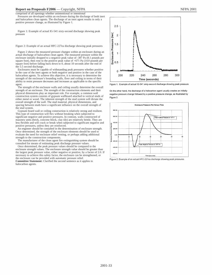
2001-33
Report on Proposals F2006 — Copyright, NFPA NFPA 2001 comprised of all openings whether unintentional or intentional Pressures are developed within an enclosure during the discharge of both inert and halocarbon clean agents. The discharge of an inert agent results in only a positive pressure change, as illustrated by Figure 1. Figure 1: Example of actual IG-541 sixty-second discharge showing peak pressure Figure 2: Example of an actual HFC-227ea discharge showing peak pressures Figure 2 shows the measured pressure changes within an enclosure during an actual discharge of halocarbon clean agent. The measured pressure within the enclosure initially dropped to a negative peak value of -387 Pa (8.1 pounds per square foot), then rose to the positive peak value of +671 Pa (14.0 pounds per square foot) before falling back down to 0, about 10 seconds after the end of the 5.5 second discharge. Enclosures must be capable of withstanding peak pressures whether positive in the case of the inert agents or both negative and positive in the case of the halocarbon agents. To achieve this objective, it is necessary to determine the strength of the enclosure’s bounding walls, floor and ceiling in terms of their ability to resist pressure decreases and increases as applicable to the specific agent. The strength of the enclosure walls and ceiling usually determine the overall strength of an enclosure. The strength of the construction elements and their physical dimensions play an important role. For example, a common wall construction system consists of gypsum wallboard attached to vertical studs of either metal or wood. The inherent strength of the stud system will dictate the overall strength of the wall. The stud material, physical dimensions, and spacing between studs have a significant influence on the overall strength of the stud system. Gypsum board wall or ceiling construction is relatively strong and resilient. This type of construction will flex without breaking when subjected to significant negative and positive pressures. In contrast, walls constructed of masonry units (brick, concrete block, clay tile) are relatively brittle. They are less flexible and will crack or break when subjected to significant negative and positive pressures, unless they are reinforced. An engineer should be consulted in the determination of enclosure strength. Once determined, the strength of the enclosure elements should be used to evaluate the need for enclosure relief venting, or perhaps adding additional strength to the construction components. The manufacturer of the clean agent fire extinguishing system should be consulted for means of estimating peak discharge pressure values. Once determined, the peak pressure values should be compared to the enclosure strength values. The enclosure strength value should be greater than the largest peak pressure value, either negative or positive, by a factor of 2.0. If necessary to achieve this safety factor, the enclosure can be strengthened, or the enclosure can be provided with automatic pressure relief. Committee Statement: Clarified the second sentence as it applies to halocarbon agents.
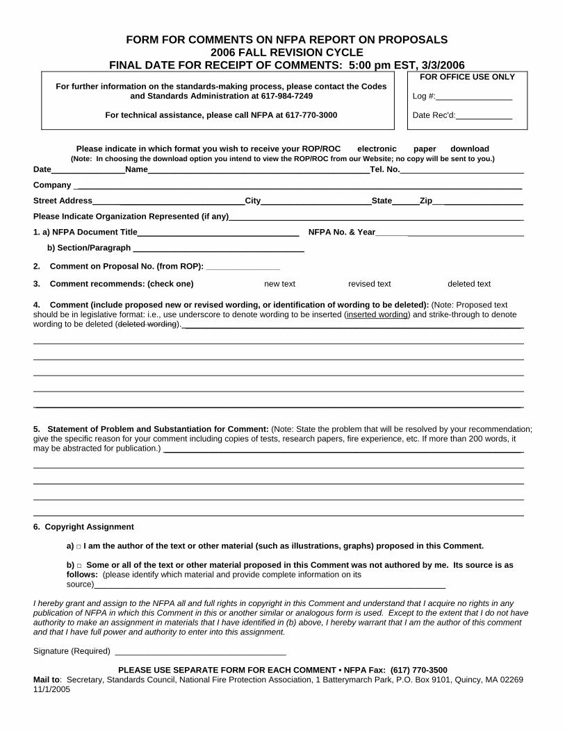
FORM FOR COMMENTS ON NFPA REPORT ON PROPOSALS 2006 FALL REVISION CYCLE
FINAL DATE FOR RECEIPT OF COMMENTS: 5:00 pm EST, 3/3/2006
For further information on the standards-making process, please contact the Codes and Standards Administration at 617-984-7249
For technical assistance, please call NFPA at 617-770-3000
FOR OFFICE USE ONLY
Log #: Date Rec'd:
Please indicate in which format you wish to receive your ROP/ROC electronic paper download
(Note: In choosing the download option you intend to view the ROP/ROC from our Website; no copy will be sent to you.) Date________________Name________________________________________________Tel. No.
Company _________________________________________________________________________________________________
Street Address_________________________________City________________________State______Zip _________________
Please Indicate Organization Represented (if any)_______________________________________________________________
1. a) NFPA Document Title___________________________________ NFPA No. & Year_______
b) Section/Paragraph _____________________________________
2. Comment on Proposal No. (from ROP): ________________
3. Comment recommends: (check one) new text revised text deleted text 4. Comment (include proposed new or revised wording, or identification of wording to be deleted): (Note: Proposed text should be in legislative format: i.e., use underscore to denote wording to be inserted (inserted wording) and strike-through to denote
ording to be deleted (w deleted wording). _________________________________________________________________
______________________________________________________________________________________________
5. Statement of Problem and Substantiation for Comment: (Note: State the problem that will be resolved by your recommendation; give the specific reason for your comment including copies of tests, research papers, fire experience, etc. If more than 200 words, it
ay be abstracted for publication.) _____________________________________________________________________m
6. Copyright Assignment
a) □ I am the author of the text or other material (such as illustrations, graphs) proposed in this Comment.
b) □ Some or all of the text or other material proposed in this Comment was not authored by me. Its source is as follows: (please identify which material and provide complete information on its source)____________________________________________________________________________
I hereby grant and assign to the NFPA all and full rights in copyright in this Comment and understand that I acquire no rights in any publication of NFPA in which this Comment in this or another similar or analogous form is used. Except to the extent that I do not have authority to make an assignment in materials that I have identified in (b) above, I hereby warrant that I am the author of this comment and that I have full power and authority to enter into this assignment. Signature (Required) _____________________________________
PLEASE USE SEPARATE FORM FOR EACH COMMENT • NFPA Fax: (617) 770-3500
Mail to: Secretary, Standards Council, National Fire Protection Association, 1 Batterymarch Park, P.O. Box 9101, Quincy, MA 02269 11/1/2005
Notice of Intent to Make a Motion (NITMAM) Sequence of Events Leading to Issuance of an NFPA Committee Document
Step 1 Call for Proposals
▼ Proposed new Document or new edition of an existing Document is entered into one of two yearly revision cycles, and a Call for Proposals is published.
Step 2 Report on Proposals (ROP)
▼ Committee meets to act on Proposals, to develop its own Proposals, and to prepare its Report.
▼ Committee votes by written ballot on Proposals. If two-thirds approve, Report goes forward. Lacking two-thirds approval, Report returns to Committee.
▼ Report on Proposals (ROP) is published for public review and comment.
Step 3 Report on Comments (ROC)
▼ Committee meets to act on Public Comments to develop its own Comments, and to prepare its report.
▼ Committee votes by written ballot on Comments. If two-thirds approve, Reports goes forward. Lacking two-thirds approval, Report returns to Committee.
▼ Report on Comments (ROC) is published for public review.
Step 4 Technical Report Session
▼ “Notices of intent to make a motion” are filed, are reviewed, and valid motions are certified for presentation at the Technical Report Session. (“Consent Documents” that have no certified motions bypass the Technical Report Session and proceed to the Standards Council for issuance.)
▼ NFPA membership meets each June at the Annual Meeting Technical Report Session and acts on Technical Committee Reports (ROP and ROC) for Documents with “certified amending motions.”
▼ Committee(s) vote on any amendments to Report approved at NFPA Annual Membership Meeting.
Step 5 Standards Council Issuance
▼ Notification of intent to file an appeal to the Standards Council on Association action must be filed within 20 days of the NFPA Annual Membership Meeting.
▼ Standards Council decides, based on all evidence, whether or not to issue Document or to take other action, including hearing any appeals.

The Technical Report Session of the NFPA Annual Meeting
The process of public input and review does not end with the publication of the ROP and ROC. Following the completion of the Proposal and Comment periods, there is yet a further opportunity for debate and discussion through the Technical Report Sessions that take place at the NFPA Annual Meeting.
The Technical Report Session provides an opportunity for the final Technical Committee Report (i.e., the ROP and ROC) on each proposed new or revised code or standard to be presented to the NFPA membership for the debate and consideration of motions to amend the Report. The specific rules for the types of motions that can be made and who can make them are set forth in NFPA’s rules which should always be consulted by those wishing to bring an issue before the membership at a Technical Report Session. The following presents some of the main features of how a Report is handled.
What Amending Motions are Allowed. The Technical Committee Reports contain many Proposals and Comments that the Technical Committee has rejected or revised in whole or in part. Actions of the Technical Committee published in the ROP may also eventually be rejected or revised by the Technical Committee during the development of its ROC. The motions allowed by NFPA rules provide the opportunity to propose amendments to the text of a proposed code or standard based on these published Proposals, Comments and Committee actions. Thus, the list of allowable motions include motions to accept Proposals and Comments in whole or in part as submitted or as modified by a Technical Committee action. Motions are also available to reject an accepted Comment in whole or part. In addition, Motions can be made to return an entire Technical Committee Report or a portion of the Report to the Technical Committee for further study.
The NFPA Annual Meeting, also known as the World SafetyConference and Exposition®, takes place in June of each year. A second Fall membership meeting was discontinued in 2004, so the NFPA Technical Report Session now runs once each yearat the Annual Meeting in June.
Who Can Make Amending Motions. Those authorized to make these motions is also regulated by NFPA rules. In many cases, the maker of the motion is limited by NFPA rules to the original submitter of the Proposal or Comment or his or her duly authorized representative. In other cases, such as a Motion to Reject an accepted Comment, or to Return a Technical Committee Report or a portion of a Technical Committee Report for Further Study, anyone can make these motions. For a complete explanation, NFPA rules should be consulted.
The filing of a Notice of Intent to Make a Motion. Before making an allowable motion at a Technical Report Session, the intended maker of the motion must file, in advance of the session, and within the published deadline, a Notice of Intent to Make a Motion. A Motions Committee appointed by the Standards Council then reviews all notices and certifies all amending motions that are proper. The Motions Committee can also, in consultation with the makers of the motions, clarify the intent of the motions and, in certain circumstances, combine motions that are dependent on each other together so that they can be made in one single motion. A Motions Committee report is then made available in advance of the meeting listing all certified motions. Only these Certified Amending Motions, together with certain allowable Follow-Up Motions (that is, motions that have become necessary as a result of previous successful amending motions) will be allowed at the Technical Report Session.
Consent Documents. Often there are codes and standards up for consideration by the membership that will be non-controversial and no proper Notices of Intent to Make a Motion will be filed. These “Consent Documents” will bypass the Technical Report Session and head straight to the Standards Council for issuance. The remaining Documents are then forwarded to the Technical Report Session for consideration of the NFPA membership.
Important Note: The filing of a Notice of Intent to Make a Motion is a new requirement that takes effect beginning with those Documents scheduled for the Fall 2005 revision cycle that reports to the June 2006 Annual Meeting Technical Report Session. The filing of a Notice of Intent to Make a Motion will not, therefore, be required in order to make a motion at the June 2005 Annual Meeting Technical Report Session. For updates on the transition to the new Notice requirement and related new rules effective for the Fall 2005 revision cycle and the June 2006 Annual Meeting, check the NFPA website.
Action on Motions at the Technical Report Session. In order to actually make a Certified Amending Motion at the Technical Report Session, the maker of the motion must sign in at least an hour before the session begins. In this way a final list of motions can be set in advance of the session. At the session, each proposed Document up for consideration is presented by a motion to adopt the Technical Committee Report on the Document. Following each such motion, the presiding officer in charge of the session opens the floor to motions on the Document from the final list of Certified Amending Motions followed by any permissible Follow-Up Motions. Debate and voting on each motion proceeds in accordance with NFPA rules. NFPA membership is not required in order to make or speak to a motion, but voting is limited to NFPA members who have joined at least 180 days prior to the session and have registered for the meeting. At the close of debate on each motion, voting takes place, and the motion requires a majority vote to carry. In order to amend a Technical Committee Report, successful amending motions must be confirmed by the responsible Technical Committee, which conducts a written ballot on all successful amending motions following the meeting and prior to the Document being forwarded to the Standards Council for issuance.
Standards Council Issuance
One of the primary responsibilities of the NFPA Standards Council, as the overseer of the NFPA codes and standards development process, is to act as the official issuer of all NFPA codes and standards. When it convenes to issue NFPA documents it also hears any appeals related to the Document. Appeals are an important part of assuring that all NFPA rules have been followed and that due process and fairness have been upheld throughout the codes and standards development process. The Council considers appeals both in writing and through the conduct of hearings at which all interested parties can participate. It decides appeals based on the entire record of the process as well as all submissions on the appeal. After deciding all appeals related to a Document before it, the Council, if appropriate, proceeds to issue the Document as an official NFPA code or standard. Subject only to limited review by the NFPA Board of Directors, the Decision of the Standards Council is final, and the new NFPA code or standard becomes effective twenty days after Standards Council issuance. The illustration on page 9 provides an overview of the entire process, which takes approximately two full years to complete.
![Report on Proposals F2006 — Copyright, NFPA NFPA 1402John M. Best, John Jay College of Criminal Justice, MD [U] Donald T. Brady, Kidde Fire Trainers, Incorporated, NJ [M] Gene P.](https://static.fdocuments.in/doc/165x107/5e7c326c47612c5c7a2726e2/report-on-proposals-f2006-a-copyright-nfpa-nfpa-1402-john-m-best-john-jay-college.jpg)


![Report on Comments F2006 — Copyright, NFPA NFPA 30James C. Brundage, III, Atlanta Fire Department, GA [E] Brian J. Clark, Liberty Mutual Group, MA [I] Rep. Property Casualty Insurers](https://static.fdocuments.in/doc/165x107/60e4d922a7485319f431a59c/report-on-comments-f2006-a-copyright-nfpa-nfpa-30-james-c-brundage-iii-atlanta.jpg)


![Report on Proposals F2006 — Copyright, NFPA NFPA 68 · 2015-11-09 · David C. Kirby, Baker Engineering & Risk Consultants, WV [SE] Richard S. Malek, Eastman Kodak Company, NY [U]](https://static.fdocuments.in/doc/165x107/5b2dad5c7f8b9adc6e8be796/report-on-proposals-f2006-copyright-nfpa-nfpa-68-2015-11-09-david-c.jpg)

![Report on Proposals F2006 — Copyright, NFPA NFPA 1981 … · Doug Stephenson, Walker County Emergency Services, GA [U] Jeffrey O. Stull, International Personnel Protection, Incorporated,](https://static.fdocuments.in/doc/165x107/5f3ac86bc9e9cb26dc08bcba/report-on-proposals-f2006-a-copyright-nfpa-nfpa-1981-doug-stephenson-walker.jpg)