
Report on Overview Assessment of ... - Pipeline Safety Trust
31
Report on Overview Assessment of the 16 Inch Diameter Olympic Pipeline Integrity to City-County Pipeline Safety Consortium of Washington November, 2001 by Bob Eiber Robert J. Eiber, Consultant Inc. 4062 Fairfax Dr Columbus, Ohio, 43220, U.S.A
Transcript of Report on Overview Assessment of ... - Pipeline Safety Trust

Report
on
Overview Assessment of the 16 Inch Diameter Olympic Pipeline
Integrity
to
City-County Pipeline Safety Consortium of Washington
November, 2001
by
Bob Eiber
Robert J. Eiber, Consultant Inc. 4062 Fairfax Dr
Columbus, Ohio, 43220, U.S.A

DISCLAIMER
This report was prepared by Robert J. Eiber, Consultant Inc. Neither Robert J. Eiber nor any person acting on his behalf assumes any liability with respect to the use of, or for any damages resulting from the use of any information, apparatus, method or process disclosed in this report.

3
Table of Contents
Executive Summary............................................................................................................................4 Objective ...........................................................................................................................................4 Bellingham Incident Summary ............................................................................................................5 Approach And Status ..........................................................................................................................5 Background Information .....................................................................................................................6 OPS Corrective Action Orders.............................................................................................................8
Corrective Action Order Items .........................................................................................................8 First COA Amendment August 10, 1999 ..........................................................................................9 Second Amendment Sept. 24, 1999 ................................................................................................11 Repair Methods Letter from OPS...................................................................................................12 In Line Inspection Dig Criteria Letter from OPS ............................................................................13
Assessment of the Integrity of the Olympic 16 inch line from Ferndale to Renton, Washington 15 Assessment of Potential Defects in Pipe..........................................................................................15 In Line Inspection Results for 16 inch Pipeline................................................................................16 Hydrostatic Test Results ................................................................................................................24 Remaining Integrity Assessments...................................................................................................26
Other Cause Category...............................................................................................................26 Incorrect Operation by Operator Personnel.................................................................................26 Malfunction of Control or Relief Equipment ..............................................................................26
Additional Line Inspections ...............................................................................................................27 Olympic Pipeline – Revised Repair Project-Excavation Basis ..........................................................27
Conclusions .....................................................................................................................................30 References .......................................................................................................................................31

4
OVERVIEW ASSESSMENT OF THE 16 INCH DIAMETER OLYMPIC PIPELINE INTEGRITY
EXECUTIVE SUMMARY An integrity assessment has been conducted on the 16 inch diameter Olympic Pipeline from Ferndale to Renton, Washington following the accident in Bellingham Washington on June 10, 1999. The integrity of the pipeline was assessed against the incident causes identified in the Office of Pipeline Safety (OPS) database of liquid pipeline incidents. The OPS incident causes can be grouped into three categories 1) defects in the pipe, 2) incorrect operation by the operator and 3) malfunction of control or pressure relief equipment. The assessment of defects in the pipe was based on in-line inspection, verification digs and hydrostatic testing applied to the pipe. The assessment of incorrect operation by operator and malfunction of control or pressure relief equipment was based on discussions with Olympic management to identify the changes that have been implemented to prevent these categories of incidents. The report presents a review of the U.S. Department of Transportation Office of Pipeline Safety (OPS) corrective action orders, the OPS requirements for inspection of indications from the in-line inspection tools, and a review of the in-line inspection indications that were dug up for examination and repaired or replaced. The Corrective Action Orders issued by the OPS have provided conservative criteria for assessing the in line inspection tool log and the dig criteria for this line segment. They have required removing a number of anomalies (non-injurious) from the pipeline that would not be considered as defects (injurious). In addition, they have also required the removal of several defects that were detected. Based on the review, the author believes the Olympic 16 inch pipeline could now have the line pressure increased to 100 percent of the maximum allowable operating pressure. This assumes that Olympic management will strive to prevent large numbers of pressure cycles from occurring and that they will continue to improve the SCADA leak detection system reliability as they have planned . The author believes that the take over of this line by BP has significantly improved the integrity assessment that has been applied to this pipeline. They have done what was needed to assess the integrity of this line segment. The result is that the line has been inspected to a level that would exceed a hydrotest to 100 percent of the specified minimum yield strength of the pipe, which is the aim level of integrity in the assessment of corrosion anomalies in the American Society of Mechanical Engineers document B31 G. Finally, it was concluded that the proposed revised ILI dig criteria provide an acceptable level of integrity with one exception, coupled with a management process instilled to control pressure cycling. The one exception to the proposed dig criteria revision was identified in this study, which was to change the dig criteria for top of the pipe dents from the proposed 0.25 inch depth to 0.20 inch depth to make sure that potentially injurious dents that could have mechanical damage or gouges in them are not missed.
OBJECTIVE
The objective of this review of the Olympic Pipeline was to assist the City-County Safety Consortium to determine if the actions taken by Olympic and OPS are prudent actions with regard to the future operability and safety to the public of the 16 inch diameter Olympic Pipeline. This concern was raised by the incident that occurred in Bellingham in 1999.

5
BELLINGHAM INCIDENT SUMMARY The Bellingham incident occurred on June 10, 1999 at approximately 3:30 p.m. at the Bellingham water treatment plant, near Watch Creek. 1 (References are at the end of the text.) The pipeline involved was a 16 inch diameter 0.312 inch wall thickness grade X52 (52,000 pi yield strength) steel pipe manufactured by Lone Star Steel. The rupture occurred on the top of the pipe in an area of external surface damage that appeared to have been produced by excavation equipment. The fracture initiated at a gouge on the pipe surface that was oriented longitudinally along the pipe. The wall thickness of the pipe at the fracture origin was measured to be between 0.24 and 0.25 inches; a reduction in thickness of approximately 20% from the original 0.312 inch wall thickness1. The pressure in the pipe that caused the rupture was elevated above the normal operating pressure of 1370 psig as a result of the closing of a pressure relief valve at the Bayview downstream pumping station.1 The relief valve closing caused a main line block valve at the station to close, which caused the pressure in the line to increase. After the accident, Olympic calculated the pressure at the rupture location to be 1456 psig1. According to the 49 CFR Part 195, the maximum allowable surge pressure for this pipeline is 1507 psig1. As a result of the rupture approximately 225,000 gallons of gasoline were released over a several hour period into Whatcom Creek and flowed westward toward the city of Bellingham2. At about 5:02 p.m., the released gasoline ignited. Two young boys and one young man lost their lives as a consequence of the accident. After the incident, OPS issued a corrective action ordera restricting the operating pressure on the pipeline system to 80 percent of the maximum operating pressure and requiring a number of safety measures for the pipeline to be reassessed. (Footnotes are indicated by alphabetical letters and appear at the bottom of the page.)
APPROACH AND STATUS The approach that has been used in this review is: 1. To assess the inspections and hydrostatic tests of the pipeline to check that all potentially injurious
defects have been detected and removed or repaired. This was accomplished by monitoring the results of the detailed inspections of the anomalies detected during in line inspection (ILI) comparing predicted anomaly sizing and type with actual sizing and type from the sites that were dug up after the internal inspection, and to assess the hydrostatic testing applied to the pipeline segment.
2. To review and comment on the corrective action orders issued by OPS, 3. To work with OPS in establishing inspection criteria for dig inspections on anomaliesb detected
during in line inspection of the pipeline, 4. To discuss with Olympic personnel, the steps that have been implemented to assure that incidents due
to operator control and malfunction of pressure relief equipment will be prevented. The results of these four activities are presented herein. a Corrective action orders 7, 9, 19 b The term anomaly is used to indicate that there is an indication of something in the pipe that has been detected in an inspection but the anomaly needs to be inspected to define whether it is an injurious defect that can result in a leak or rupture that needs to be removed or repaired.
6
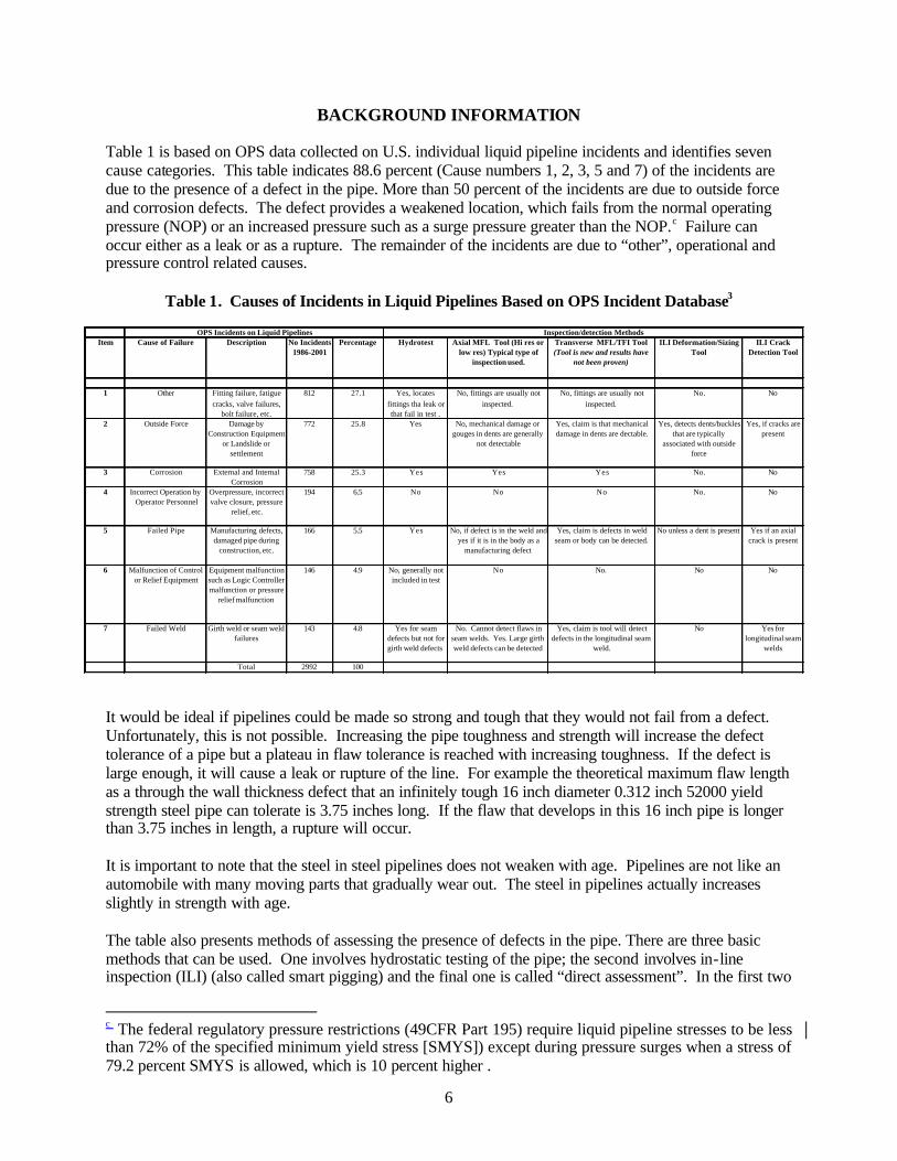
BACKGROUND INFORMATION Table 1 is based on OPS data collected on U.S. individual liquid pipeline incidents and identifies seven cause categories. This table indicates 88.6 percent (Cause numbers 1, 2, 3, 5 and 7) of the incidents are due to the presence of a defect in the pipe. More than 50 percent of the incidents are due to outside force and corrosion defects. The defect provides a weakened location, which fails from the normal operating pressure (NOP) or an increased pressure such as a surge pressure greater than the NOP. c Failure can occur either as a leak or as a rupture. The remainder of the incidents are due to “other”, operational and pressure control related causes.
Table 1. Causes of Incidents in Liquid Pipelines Based on OPS Incident Database3
It would be ideal if pipelines could be made so strong and tough that they would not fail from a defect. Unfortunately, this is not possible. Increasing the pipe toughness and strength will increase the defect tolerance of a pipe but a plateau in flaw tolerance is reached with increasing toughness. If the defect is large enough, it will cause a leak or rupture of the line. For example the theoretical maximum flaw length as a through the wall thickness defect that an infinitely tough 16 inch diameter 0.312 inch 52000 yield strength steel pipe can tolerate is 3.75 inches long. If the flaw that develops in this 16 inch pipe is longer than 3.75 inches in length, a rupture will occur. It is important to note that the steel in steel pipelines does not weaken with age. Pipelines are not like an automobile with many moving parts that gradually wear out. The steel in pipelines actually increases slightly in strength with age. The table also presents methods of assessing the presence of defects in the pipe. There are three basic methods that can be used. One involves hydrostatic testing of the pipe; the second involves in-line inspection (ILI) (also called smart pigging) and the final one is called “direct assessment”. In the first two
c The federal regulatory pressure restrictions (49CFR Part 195) require liquid pipeline stresses to be less than 72% of the specified minimum yield stress [SMYS]) except during pressure surges when a stress of 79.2 percent SMYS is allowed, which is 10 percent higher .
Item Cause of Failure Description No Incidents 1986-2001
Percentage Hydrotest Axial MFL Tool (Hi res or low res) Typical type of
inspection used.
Transverse MFL/TFI Tool (Tool is new and results have
not been proven)
ILI Deformation/Sizing Tool
ILI Crack Detection Tool
1 Other Fitting failure, fatigue cracks, valve failures,
bolt failure, etc.
812 27.1 Yes, locates fittings tha leak or that fail in test .
No, fittings are usually not inspected.
No, fittings are usually not inspected.
No. No
2 Outside Force Damage by Construction Equipment
or Landslide or settlement
772 25.8 Yes No, mechanical damage or gouges in dents are generally
not detectable
Yes, claim is that mechanical damage in dents are dectable.
Yes, detects dents/buckles that are typically
associated with outside force
Yes, if cracks are present
3 Corrosion External and Internal Corrosion
758 25.3 Yes Yes Yes No. No
4 Incorrect Operation by Operator Personnel
Overpressure, incorrect valve closure, pressure
relief, etc.
194 6.5 No No No No. No
5 Failed Pipe Manufacturing defects, damaged pipe during
construction, etc.
166 5.5 Yes No, if defect is in the weld and yes if it is in the body as a
manufacturing defect
Yes, claim is defects in weld seam or body can be detected.
No unless a dent is present Yes if an axial crack is present
6 Malfunction of Control or Relief Equipment
Equipment malfunction such as Logic Controller malfunction or pressure
relief malfunction
146 4.9 No, generally not included in test
No No. No No
7 Failed Weld Girth weld or seam weld failures
143 4.8 Yes for seam defects but not for girth weld defects
No. Cannot detect flaws in seam welds. Yes. Large girth weld defects can be detected
Yes, claim is tool will detect defects in the longitudinal seam
weld.
No Yes for longitudinal seam
welds
Total 2992 100
Inspection/detection MethodsOPS Incidents on Liquid Pipelines

7
methods, the pipe is either stressed in a pressure test or inspected with tools that can detect anomalies in the pipe, which are then dug up and examined in detail. The third involves data from operational experience coupled with surface measurements to locate areas of cathodic protection current loss to assess the integrity of a pipeline. Hydrostatic testing requires water be placed in the pipe and the pressure increased to a test pressure in excess of the maximum operating pressure (MOP) for a minimum of 4 hours. The benefit of hydrostatic testing is that it demonstrates that the pipe can withstand a higher pressure than the MOP usually 125 percent or a stress equal to 90 percent of the SMYS. The negative side of hydrostatic testing is that it only detects those defects that are large enough to fail in the test and that are oriented perpendicular to the maximum stress in the pipe, which is the hoop stress. This means that circumferential anomalies in girth welds will not be detected in a hydrostatic pressure test. If an anomaly exists that is too small to fail in the test, it will survive the test. Unfortunately, tests that are conducted to 85 to 90 percent SMYS as required under current Federal regulations can leave large defects and these can grow in service from cycles of pressure and fail at a later date. The use of repeated high pressure hydrostatic tests on a pipeline is generally to be avoided as they can cause growth of anomalies into defects, which would not have occurred in the absence of repeated high pressure testing. ILI involves the placement of an inspection device (commonly called a smart pig) into the pipeline, which is propelled through the pipe by the fluid in the line. The inspection capability of the inspection device is a function of the inspection technology in the device. There are several technologies that are being used on inspection tools such as: • Deformation tools measure the depth of dents in the surface of the pipe based on the inward
projection of the pipe measured with mechanical fingers or a flexible cup and provide a data log that defines the depth of a dent, its location around the circumference and along the pipe and because of multiple sensors the shape of the dent.
• Axial flux Magnetic Flux Leakage (MFL) tools impose a magnetic flux field along the axis (length) of the pipe and measure wherever the magnetic field has been pushed out of the pipe wall by an anomaly. The resulting signal is recorded to locate axially and circumferentially the position of the anomaly. The shape and magnitude of the signal provides information on the depth of the anomaly but the signal is not in a one to one relationship with anomaly depth. Thus, if the height of a signal doubles it does not mean that the defect is twice as deep. There are also many other pipeline features that provide signals such as tees, elbows, taps, bends, wall thickness changes etc. and these must be sorted from the anomaly signals. These tools have been available for over 35 years and are normally thought of as capable of detecting metal loss (corrosion), circumferential cracks such as in girth welds, and mechanical damage (gouge and dents). They have a low sensitivity to the detection of mechanical damage suggesting that significant mechanical damage anomalies may be missed. Because of the axial flux field orientation, they are not able to detect longitudinally oriented flaws such as seam weld defects or axial cracks in the pipe body. (To detect an anomaly the flux field must be approximately perpendicular to it.)
• Transverse flux MFL tools (frequently called TFI, transverse flux inspection). These tools are similar to the axial flux MFL tools but the magnetic flux field is oriented circumferentially. The reorientation of the flux field facilitates detection of seam defects, axial cracks as well as corrosion metal loss defects. At the present time, these tools are new and are undergoing evaluation tests to see if they can reliably detect all of the injurious defect types. The one anomaly that TFI will miss is a circumferentially oriented girth weld defect. This is not a serious defect in pipelines as it is responsible for less than 5 percent of the service incidents and usually requires a secondary loading for failure.
• Ultrasonic metal loss tools send an electronic signal perpendicular to the pipe thickness to an anomaly, which reflects it back to the receiver. These tools measure the depth of metal loss based on the time of flight of the signal. Thus, the tool measures the wall thickness of the pipe and
8
where the wall thickness is reduced an anomaly is indicated. The capabilities are about the same as the axial flux MFL tool.
• Crack detection tool. The crack detection tool is an ultrasonic tool with an electronic signal that is inserted into the pipe at an angle to the pipe surface and detects and sizes axial cracks in pipe. This type of tool is relatively new and is not commonly used on liquid pipelines for the detection of anomalies because it does not detect metal loss or outside force damage.
OPS CORRECTIVE ACTION ORDERS Following the Bellingham accident, OPS issued a corrective action order with several amendments. The first corrective action order (CAO) was issued on June 18, 1999. d Following each item are an assessment of what the item accomplished. Corrective Action Order Items 1. Do not operate the segment of pipeline from Ferndale to Allen, Washington until completing Items 2
through 4, and obtaining the written approval of the Regional Director, Western Region of the plan provided for in Item 5. This was an appropriate step to prevent further problems with this line since the cause of the rupture was unknown at this timee.
2. Review the Supervisory Control and Data Acquisition System (SCADA) to determine the cause of the deficiencies that occurred on June 10, 1999, and correct these deficiencies. The SCADA system prior to the rupture shut down and this CAO requires Olympic to find the cause and correct it.
3. Test mainline valves intended to isolate sections of the pipeline traversing populated and environmentally sensitive areas. Take any needed remedial action to assure that will they perform their intended function. A large volume of fluid escaped from the pipeline and this was an attempt to make sure the valves operated as intended. Valves are not a preventative safety item as they can only limit the consequences of an accident by limiting the release of f luid.
4. Install a check valve adjacent to the Lakeway Drive block valve at milepost 16.22. This is an attempt to slow release of fluid from the pipeline prior to closure of the mainline block valve. Check valves do not seal tightly but can significantly reduce the volume of liquid that can escape from a line.
5. Develop a plan with corrective measures that address factors playing a role in the release. The plan must include the following items to the extent that they address factors in the release: a) A review of the existing mainline block valves and check valves taking into consideration
elevation, population, and environmentally sensitive locations, and plan for additional mainline block valves and check valves to minimize the consequences of a release from the pipeline. The block valves will have remote operation capability as deemed appropriate by the review.
b) A comprehensive review of SCADA to detect any deficiencies, with a schedule for modifications. c) Cathodic protection surveys with scheduled remedial action. d) Pressure testing. e) Internal inspection tool surveys and remedial action to assure the integrity of the pipeline. The
type of internal inspection tool used shall be the best available technology appropriate for accessing the system based on the type of failure that occurred on June 10, 1999. This plan is needed and should be implemented before the line can operate at full line pressure.
6. Submit the written plan to the Director, Western Region, Office of Pipeline Safety, RSPA, 12600 West Colfax Ave. Suite A250, Lakewood, CO 80228.
d The COA’s are available on the dot web site at ops.dot.gov/bellingham1/documents/ e Italicized text represents the author’s comments on the COA.

9
7. Restrict the MOP of the Ferndale, Washington to Allen, Washington to 1056 psig, which is 80% of the NOP. Equilon may request approval from the Associate Administrator, OPS to increase its pressure based on a showing that the hazard has been abated. OPS’ approval must be in writing. Very appropriate as this lets the operating pressure at the time of failure act as a 125% proof test pressure of the pipeline and operation is then at 80% of it providing a reasonable margin of safety on pressure that has historically proven very reliable.
8. Implement the plan in Item 5 and coordinate all corrective action with the Regional Director, Western Region, OPS to assure the integrity of the pipeline.
9. Restrict the MOP of the 16 inch Allen, Washington to Renton, Washington segment to 80% of its NOP. Equilon may request approval from the Associate Administrator, OPS to increase its pressure based on a showing that the hazard has been abated. OPS’ approval must be in writing. Very appropriate as this lets the operating pressure at the time of failure act as a 125% proof test pressure of the pipeline and operation is then at 80% of prior operating pressure providing a margin of safety that has historically proven reliable.
10. Include consideration of 16 inch Allen, Washington to Renton, Washington segment within the plan developed under Item 5.
11. The Regional Director may grant an extension of time upon receipt of a written request stating the reasons therefor, for completion of any of the items required under an approved plan.
First COA Amendment August 10, 1999 Item 5 is amended to read: e) Internal inspection tool surveys and remedial action to assure the integrity of the pipeline. The type of internal inspection tool used shall be the best available technology appropriate for accessing the system based on the type of failure that occurred on June 10, 1999. I do not see a change from the original Item 6 is amended to read: 6) Submit the written plan to the Director, Western Region, Office of Pipeline Safety, RSPA, 12600 West Colfax Ave. Suite A250, Lakewood, CO 80215-3736. Only change appears to be a corrected zip code. Items 7 and 9 are amended to read as follows: 7. Restrict the MOP of the Ferndale, Washington to Allen, Washington to 1056 psig, which is 80% of the NOP or 80 % of the surge pressure at the point of failure, whichever is lower. Equilon may request approval from the Associate Administrator, OPS to increase its pressure based on a showing that the hazard has been abated. OPS’ approval must be in writing. The surge pressure limitation was added just in case the surge pressure was lower than the NOP. 9. Restrict the MOP of the 16 inch Allen, Washington to Renton, Washington segment to 80% of its NOP or 80 % of the surge pressure at the point of failure, whichever is lower. Equilon may request approval from the Associate Administrator, OPS to increase its pressure based on a showing that the hazard has been abated. OPS’ approval must be in writing. The surge pressure limitation was added just in case the surge pressure was lower than the NOP. Additional items: 12. For a minimum period of one (1) year after the last change to the SCADA system undertaken
because of Item 2 has been completed, monitor the operations of the SCADA system for anomalies in the operation including, but not limited to, all processing errors, computer slow downs, unintended defaults to the backup computer system, and communications failures. Report each anomaly in writing to the Director, Western Region, OPS within 2 weeks of its occurrence. This is a good chance to make sure the SCADA system doesn’t start to malfunction without OPS/Olympic knowing

10
it. 13. Within 3 months of issuance of the Amendment, do the following with respect to persons involved
controlling the operations of the pipeline through the SCADA system. a) Develop and implement a training program for controllers specific to the SCADA system in use
that includes responding to abnormal operations and starting up and shutting down any part of the pipeline system.
b) In addition to the training, review the qualifications of each controller to perform his or her duties and to recognize conditions that are likely to cause emergencies and be able to predict the consequences of facility malfunctions or failures such as those that occurred on June 10, 1999.
c) Provide specific, specialized, technical training to controller personnel responsible for maintenance and operation of the hardware and software components of the SCADA systems.
d) Review the qualification of the personnel responsible for maintenance and operation of the hardware and software components of the SCADA systems to assure that they can perform the functions needed. This is a good step since the operators restarted the pumps after the SCADA system went down.
e) In training provided under this item, include classroom and practical exercises and use of a pipeline simulator as appropriate.
14. Perform a design review of the Ferndale to Renton segment to ensure the station safety devices will shut the segment down within applicable parameters. This review will include at least the following: a) A surge analysis using the worst case scenario, i.e. highest flow rates using drag reducing agent
with the shortest possible valve closure times and the highest density product; b) A test of the relief valves to determine that capacity is adequate and each valve operates reliably;
and c) A design review of the physical piping in the Bayview terminal that includes the interaction of all
station safety devices. This is an appropriate action since the surge pressure in the Bellingham failure was produced by problems associated with the pressure relief valve at the Bayview station.
15. In conducting any internal inspection, including any required under this Order, excavate and visually examine any anomaly that could be associated with excavation damage which is identified in the top half of the pipe, and take appropriate remedial action with respect to each. This is an absolute necessity as internal inspection or in line inspection devices are fairly good at detection but experience has shown that they are not as accurate in the characterization of the length and depth of defect.
16. In conducting any internal inspection, including any required under this order, consider the possibility of internal corrosion in conducting the inspection and in analyzing the results. This is excellent in that occasionally metal loss will be indicated on an inspection log but none is found on the outside pipe surface and it is located on the inside surface. If field dig ultrasonic wall thickness measurements are made from the outside surface then internal corrosion can be assessed and confirmed or rejected.
17. Review existing procedures for normal, abnormal, and emergency operations of the Ferndale to Allen Segment and make any necessary changes to insure that they address operations at the Bayview Products Terminal. A good step to make sure the two stations are compatible.
18. Prior to undertaking any testing, repairs, or construction needed to prepare for the return of the pipeline to service or for a rerouting of the pipeline, notify the Director, Western Region, and submit plans for the testing or repairs or comprehensive construction specification unless told by the Director that it is not necessary in a particular situation. This appears to be a check that what will be undertaken as remedial measures are appropriate.

11
Second Amendment Sept. 24, 1999 19. With respect to operating pressure,
a) maintain normal operating pressures on the following segments not to exceed 80% of the maximum operating pressure (MOP) previously established for each segment: i) the 20-inch Allen to Renton segment, ii) the 14-inch Renton to Portland segment, iii) the 16-inch Anacortes to Allen segment, and iv) the various short delivery segments on the system.
If necessary, reduce current operating pressures to achieve this. This reduces the pressure on the complete Olympic Pipe Line System as a protection for the public (b) A request for relief from pressure restriction with respect to one of the segments may be made
prior to a decision to close this action based on completion of the Corrective Action Order. The request must be accompanied by a written showing that the segment can be operated safely at the normal pressures. It may be granted by the Regional Director. A denial may be appealed to the Associate Administrator.
20. Conduct hydrostatic pressure testing at a test pressure of 90% of SMYS for a minimum period of eight hours as follows: (a) pressure test the Ferndale to Allen 16-inch segment of the system in its entirety; (b) pressure test any section of the remainder of the Olympic Pipeline system that are constructed of
pre-1970 ERW pipe manufactured by Lone Star; (c) Pressure test any remaining sections of the Olympic Pipeline system if pressure testing is
indicated by the evaluation and plan provided for in item 21. (d) Metallurgically test any failure that occurs in a manner, which will identify the cause of failure
including possible cyclic fatigue. This is a necessary requirement to protect the public since the existing in line inspection smart pig tools have not yet been verified as capable of inspecting the ERW seam weld. Lone Star pipe was singled out because it was produced with low frequency welding current that has had a tendency to leave unbonded areas in the weld. These unbonded areas can cause seam ruptures.
21. If during the pressure testing required by item 20a. a failure occurs on line pipe which was not manufactured by Lone Star, evaluate the need to pressure test the remainder of the Olympic Pipeline system and plan any pressure testing that the evaluation indicates is advisable. The evaluation and plan are to done as follows: (a) The evaluation must take into account the failure mode, the characteristics of the pipe, the
pressure at the time of failure, the existence of other alternative assurances of integrity, and other factors relevant to a decision of the risk of a similar failure. For example, if the failure occurred in a longitudinal seam, pressure testing of any segment containing pipe of the same manufacture as that which failed should be done. If the failure was not in the longitudinal seam, the failure mode as determined by metallurgical testing and internal inspections required under this order or voluntarily done should be considered.
(b) Submit the evaluation and the plan to the Regional Director for approval. This is to make sure that if other ERW pipe failures occur during pressure testing that other pipe from the same mill and vintage is also tested to protect the public. The first hydrotest failure occurred in Lone Star pipe and they tested the complete segment from Ferndale to Allen. The second hydrotest failure occurred in US Steel pipe but was not in the Ferndale to Allen segment and therefore Item 20 does not require the remainder of the line to be tested.
22. Notwithstanding the provisions of 49 C.F.R. §195.406 regarding the establishment of MOP based upon pressure testing, a pressure test conducted pursuant to this Corrective Action Order may not be

12
used to establish a higher MOP than that previously established for the segment absent written concurrence of the Associate Administrator, OPS. This prevents Olympic from attempting to establish a new higher operating pressure which is unlikely since the current MOP is at the limit of allowable stress according to Part 195.
23. In conducting internal inspections on the Olympic Pipeline system including those provided for in items 5, 15, and 16, do the following: (a) Select internal inspection devices that can accurately detect metal loss, pipe deformation, and
enable strain calculation to be conducted. (b) Complete the analysis of internal inspection data and any remedial actions for anomalies that
affect pipeline integrity within six months of completion of an internal inspection. The analysis shall include a comparison of metal loss with pipe deformation.
(c) Develop and follow written procedures for the conduct of internal inspections that includes fitness for service criteria for identifying, prioritizing, and correcting defects. These shall include criteria for deciding on direct pipeline examination further integrity assessment, and corrective measures including repair, replacement, or operational restrictions. At a minimum, consider the criteria established in ASME B31-4 and ASME B31-G. OPS subsequently issued criteria for inspecting anomalies and which anomalies are to be dug up, exposed and inspected in detail-see Tables 2 and 3 for a list of the anomalies inspected in detail.
24. Within 6 months of completion of the management audit provided for in the City Agreement, implement any corrective measures that cover matters regulated in 49 C.F.R. Part 195 and report progress on the implementation to the Regional Director periodically, but no less frequently than every three months. As the management audit nears, completion, Respondent may request that OPS specify which corrective actions are subject to this item.
Repair Methods Letter from OPS The following is a letter from Chris Hoidel of OPS to Carl Gast V.P. and General Manager of Olympic June 22, 2000 defining, which repair methods are acceptable to OPS. “Thank you for your correspondence dated June 14, 2000, regarding your proposed repair methods for defects at Mileposts 27.02, 25.52, 26.06, and 26.10 in the Ferndale to Allen segment of your 16-inch pipeline. The correspondence requests my concurrence with the Olympic Pipe Line Company (Olympic) plans and procedures for repair of the above mentioned defects. Further, you indicate your plans and procedures are based on research completed by PRC International presented in a report titled "Repair of Pipeline Dents Containing Minor Scratches" by John Kiefner and Christopher Alexander. The Office of Pipeline Safety (OPS) has great respect for the aforementioned authors and their work regarding pipeline repairs, however, it must be acknowledged the referenced research has not yet been incorporated into the industry standards. The OPS believes these studies will demonstrate the industry standards are conservative regarding repairs to all your pipelines.” “The OPS recognizes the ASME B31.4 Code for Pressure Piping as the industry standard governing repairs to hazardous liquid pipelines. The OPS believes a conservative application of the repair standards in this document is an appropriate application regarding repairs to your pipelines. In regard to defects identified on the out-of-service Ferndale to Allen segment of your pipeline: in accordance with paragraph 451.6.2(b)(1) of the B31.4 Code the pipeline, repairs will be made by cutting out a cylindrical piece of pipe containing the defects and replacing it with pipe meeting the requirements of paragraph 401.2.2, of the B31.4 Code, and having a length of not less than one-half of the pipe diameter.” “As specified in paragraph 451.6.2(b)(2) of the B31.4 Code, repairs to pipeline segments which can be demonstrated as not practical to take out of service are to be made by installation of a full encirclement

13
welded split sleeve in accordance with paragraph 451.6.2(c) or other repair methods listed under paragraph 451.6.2(b) Allowable Pipeline Repairs.” “Due to concerns regarding cyclic fatigue acting on stress concentrators in hazardous liquid pipelines the following is required in excess of the B31.4 Code:
1) Identified excavated gouges and grooves not coincident with dents having a depth less than 12.5 percent of the nominal wall thickness will be repaired by grinding in such a manner as to remove the stress concentrator. 2) Dents of depths equal to 2 percent but less than 6 percent of the nominal pipe diameter in the top half of the pipeline (9:00 o'clock to 3:00 o'clock) not containing stress concentrators, cracking, or mechanically induced metal loss damage will be repaired by full encirclement welded split sleeve or composite reinforcement sleeve applied in such a manner so as to restrain the dent. 3) As an alternate to repairing the dents described in item 2) above: if cyclic fatigue evaluations can be provided that validate the pipeline's ability to be returned to service without concern relative to pipeline integrity compromises as a result of cyclic fatigue, (as per the work described in "Effects of Smooth and Rock Dents on Liquid Petroleum Pipelines" API Publication 1156, November 1997, authors Christopher Alexander and John Kiefner), then, no repairs will be required.”
“The OPS believes repairing the pipeline to the most current industry standard will assure pipeline integrity. Thank you for your cooperation in this important safety matter.” As will be shown, Olympic has complied with these requirements in repairing anomalies found on the pipeline. Three methods of repair were used, pipe cut out and removal, clocksprings, and grind and recoat as will discussed later in this report. In Line Inspection Dig Criteria Letter from OPS f On August 10, 2000 Chris Hoidel of OPS sent the following letter to Bobby Talley, Vice President of Olympic describing which anomalies identified by in line inspection tools should be dug up and inspected in detail. On June 2, 2000, Mr. Carl Gast, then Vice President and Manager of Olympic Pipe Line Company (Olympic), provided the Office of Pipeline Safety (OPS) with correspondence regarding the In-Line Inspection (ILI) evaluation criteria as discussed during the May 31, 2000, telephone conference. The telephone conference resulted in additional anomaly evaluation criteria being incorporated into Olympic's ILI Plan for the Femdale to Allen segment of the 16-inch pipeline. The application of this additional criteria has proven to be critical for identifying top side anomalies (9:00 to 3:00 o'clock) associated with excavation damage often resulting in pipeline dents with associated gouges and cracks. Excavations of coincident anomalies for the Ferndale to Allen pipeline segment resulted in identifying several dents with associated gouges and cracks. Due to the successful application of the criteria in this segment of pipeline and the critical nature of these anomalies, OPS believes the improved evaluation criteria, as stated below, should be applied to your pipeline system in its entirety. It is my understanding British Petroleum as the new operating partner of Olympic has agreed to the implementation of the improved criteria for the evaluation of anomalies for the entire pipeline system. The purpose of this correspondence is to formalize our understanding of the evaluation criteria as stated below: The following criteria will be applied regarding the evaluation of ILI survey results for the entire Olympic pipeline system: 1) All deformation anomalies greater or equal to 0.10-inches will be noted for further evaluation. f R. Eiber on behalf of the City-County Consortium consulted with OPS as these criteria were developed.

14
2) The deformation anomalies identified in Item 1 above will be sorted for top side anomalies occurring from the 9:00 to 3:00 o'clock position on the pipeline.g 3) All deformation anomalies greater than or equal to 6 percent of the pipe diameter will be excavated and evaluated for repair. 4) The 1996 Tuboscope MFL data will be evaluated at each location identified in Item 1 above in an attempt to identify coincident metal loss and/or coincident longitudinal weld and/or coincident girth weld. 5) The 2000 MFL data will be evaluated at each location identified in Item 1 above in an attempt to identify coincident metal loss and/or coincident longitudinal weld and/or coincident girth weld. 6) The OPS, Olympic, and Tuboscope ILI Consultants will review the ILI data and eliminate anomalies not meeting the excavation criteria. The Tuboscope data analyst will be allowed to perform initial grading of the logs and the overlay of data without disturbance. The OPS ILI Consultant will have access to any and all data and materials, as he deems necessary, for making an informed opinion regarding the determination of which anomalies must be excavated and evaluated for repair. 7) Any anomaly with a deformation greater than or equal to 0.10 inches, on the top side of the pipe, with a coincident metal loss feature or confirmed coincident weld (longitudinal or circumferential) presence from the MFL data, will be excavated and evaluated. Any anomaly with a deformation greater than or equal to 0.10 inches, on the top side of the pipe (9:00 to 3:00 o'clock position), where the weld (longitudinal or circumferential) can not be confirmed to be non-coincident with the deformation will be excavated and evaluated for repair. Any anomaly with a deformation greater than or equal to 0.10 inches, on the top side of the pipe (9:00 to 3:00 o'clock position) that is considered to be highly suspect of being caused by impact from an outside force due to it's signal character within the MFL data will be excavated and evaluated for repair. 8) Tuboscope will grade all MFL anomalies not subject to the overlay requirements mentioned above to a minimum depth criteria of equal to or greater than 40 percent for straight runs of pipe and 20 percent for areas within 12 inches of circumferential welds. 9) All MFL anomalies having a depth greater than or equal to 80 percent of the wall thickness, or having a B31-G calculation of less than or equal to 100 percent of MOP, will be excavated and evaluated for repair. 10) All confirmation and anomaly excavations will be inspected by an OPS representative prior to re-coating and backfilling the pipeline. 11) The reports for anomaly excavations, and any other requested documentation by OPS, will be provided to OPS as excavations are completed in the format referenced in your June 2, 2000, correspondence and including the following: - Anomaly Evaluation Site Summary Report - Deformation 2000 "ASCAN" and "BSCAN" - MFL 2000 "ASCAN", "BSCAN", and ID/OD 12) The OPS will be provided the information in Item 11 by email as the data becomes available followed by a CD-ROM disk as the information is formalized. The OPS appreciates your cooperation in adopting the improved evaluation criteria assuring improved
g In the revised dig criteria, Olympic increased the coverage to 4 to 8 o’clock.

15
pipeline integrity for your pipeline system. Additionally, thank you for participating in the public forum held in Bellingham, Washington, on August 8, 2000. These criteria were developed to make sure that metal loss that might impact the integrity of the pipeline are included in the digs to be performed to validate the ILI log. The assessment of the corrosion is to be conducted in accordance with ASME B31-G criteria which has been used by the industry for more than 15 years with no instances of significant metal loss having been missed during that time. Also, dents on the top half of the pipe of the pipe were to be inspected because these are the types of dents that have a high probability of having been produced by construction equipment and having gouges in them. Current MFL inspection tools cannot accurately detect mechanical damage or corrosion in dents and therefore this is a means of detecting gouges and dents, which are the most serious defects in pipelines as indicated by the Bellingham failure. The dent depth of 0.1 inch was selected on the basis that it is as shallow as can be detected with the existing deformation tools. The criteria selected are very appropriate for a first attempt to review the results of the inspection logs and to perform digs on the anomalies indicated. They have turned out to be more restrictive than necessary as will be discussed later in the report and on this basis Olympic has eased the criteria for the 20 inch diameter and other Olympic lines. Overall, the restrictions and criteria imposed by OPS are conservative, necessary to protect the public, and necessary to achieve a uniform assessment of anomalies indicated in the line from ILI tools.
ASSESSMENT OF THE INTEGRITY OF THE OLYMPIC 16 INCH LINE FROM FERNDALE TO RENTON, WASHINGTON
The 16 inch pipeline from Ferndale to Renton has been subjected to a number of integrity assessments. These assessments include: 1. In line inspection with deformation tools and high resolution (res) Magnetic Flux Leakage (MFL)
tools to located dents and metal loss. 2. Dig and inspect the anomalies identified from the deformation and ILI logs selected according to the
OPS criteria and repaired according to national standards. 3. Hydrotest the complete 16 inch pipeline from Ferndale to Renton. 4. Discuss with Olympic personnel, the steps that have been implemented to assure that incidents due to
other causes, operator control, and malfunction of pressure relief equipment are prevented. Assessment of Potential Defects in Pipe The potential defects that could cause failure of the 16 inch pipeline are indicated in Table 1 and consist of the following categories based on the OPS liquid pipeline incident database: 1. Other (fitting failure, fatigue cracks, valve failures, bolt failures, gasket failures, etc) representing
27.1 percent of the U.S. incidents , 2. Outside force (includes mechanical damage and landslide or settlement) representing 25.8 percent of
the U.S. incidents, 3. Corrosion, representing 25.3 percent of the U.S. incidents, 4. Failed pipe (manufacturing defects, damaged pipe during construction), representing 5.5 percent of
the U.S. incidents, and 5. Failed weld (includes girth and seam welds), representing 4.8 percent of the U.S. incidents. These five items total 88.6 percent of the total incidents and the remainder are due to operator error, 6.5 percent and malfunction of control or pressure relief equipment, 4.9 percent. The causes of incidents on the Olympic pipeline in the OPS database from 1985 on are a total of 15 incidents.

16
These consist of 7 in the “other” category (fittings, valves, gasket etc.), 4 due to outside force, 2 due to malfunction of control or relief equipment, 1 due to incorrect operation, and 1 due to failed pipe. The goal of this review of the 16 inch pipeline assessment was to determine if the inspection techniques applied were capable of detecting these five categories of anomalies/defects. To accomplish this Olympic used a combination of in-line inspection and hydrostatic testing. In Line Inspection Results for 16 inch Pipeline. In 2000, the Tubscope Deformation tool and the hi res MFL tool were run through the 16 inch pipeline. These tools are capable of detecting dents and metal loss. They are not capable of reliably detecting dents with gouges, and cannot detect anomalies in the ERW seam. The results are shown in Tables 3 and 4. A total of 128 anomalies were indicated. The digs at these sites revealed that 94 (73%) were dents, 20 (15.6%) were metal loss, 8 (6.7%) were taps or no defect found, and 1 was a lamination. Wherever possible the predicted metal loss depths were compared to the measured metal loss depths to assess the accuracy of the tool. The results of this comparison are shown in Figure 1.
The figure shows that with the exception of two data points (Tasks 20 and 680) basically all of the data are on or below the 1:1 line (solid line) indicating that the Tuboscope hi res MFL tool tends to overestimate the depth of metal loss defects. The two non-conservative data points outside of the 20 percent bands are 36 and 110 % in error. This is why it is necessary to dig each indication as one indication was indicated as 16.5 percent metal loss with an actual metal loss of 34.8 percent and the other as 46 percent metal loss with an actual of 81 percent.
The results indicate that the MFL ILI was able to locate and detect corrosion anomalies.
Figure 1. Ferndale to Renton Metal Loss Data Predicted Metal Loss Depth vs Measured Metal Loss Depth
Figure 2 presents data for the Ferndale to Renton dent depth predictions compared to the measured dent depths. The dent depths tend to scatter about the 1:1 line but on the average tend to fall above the 1:1 line in the non-conservative region. However, it must be pointed out that Tuboscope claims an accuracy of 2 percent of the pipe diameter for the deformation tool, which is shown in the plot. As can be observed, all but six of the data points are below this limit. The 0.1 inch dent depth that was used as a dig criteria is also shown and falls near the lower end of the dent depths observed. Although the tool was used in a
0
10
20
30
40
50
60
70
80
0 10 20 30 40 50 60 70 80Predicted MFL Metal Loss, % wall thickness
Mea
sure
d M
etal
Los
s, %
wal
l thi
ckne
ss
Ferndale to AllenAllen to Renton
Conservative
Non Conservative
20% error bands
Task 20
Task 680

17
region outside of the manufacturers stated accuracy limits, it appears to have been successful in detecting and locating dents with shallow depths. Overall, this tool tends to underestimate dent depth by approximately 0.25 to 0.5 percent of the pipe diameter. These data indicate that the deformation tool is capable of detecting and locating dents that are as small as 0.1 inch in depth. There are a total of 128 anomalies represented in Tables 2 and 3. They represent the anomaly types and the repair types shown in Table 4. Table 4 indicates that one of the main anomaly types present in the line were 94 dents (these are dents on the top half of the pipe) followed by 19 metal loss and 1 gouge anomalyh. More than half of the dents contained gouges and this is the reason for the high number of cut outs required to repair them. Industry standard B31.4 requires dents with metal wall loss or gouges to be replaced/repaired.
Figure 2. Predicted Dent Depth vs Measured Dent Depth From ILI Data
Table 2. Summary of Anomalies and Repair Methods As Presented in Tables 2 and 3. Repair Method
Defect Type Future action or No Action
Required Cut Out Pipe
Section Clockspring Grind and
Recoat Metal Loss 8 6 5
Gouge 1 Dent 62 26 6 Tap 9
Lamination 1 Reroute or pipe
replacement 3
No defect found 1 Total 128 13 72 32 11
h Metal loss is loss of wall thickness due to corrosion while a gouge is reduction in wall thickness due to mechanical damage such as from excavation equipment.
0
0.5
1
1.5
2
2.5
3
3.5
4
4.5
5
0 1 2 3 4 5
Estimated Dent Depth Based on Def. Tool, % Dia.
Mea
sure
d D
ent
Dep
th,
% D
ia.
Ferndale to Allen
Allen to Renton
Conservative
Non conservative
Tuboscope accuracy limit 2%
0.1 inch dent depth =0.625% of 16 " diameter

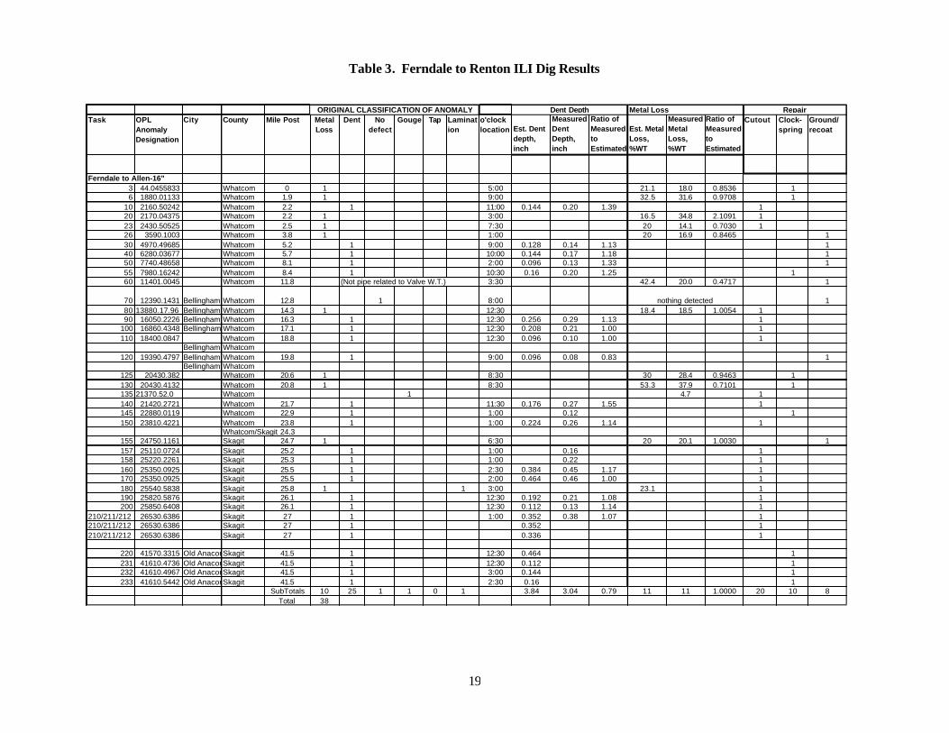
19
Table 3. Ferndale to Renton ILI Dig Results
Task OPL Anomaly Designation
City County Mile Post Metal Loss
Dent No defect
Gouge Tap Lamination
o'clock location Est. Dent
depth, inch
Measured Dent Depth, inch
Ratio of Measured to Estimated
Est. Metal Loss, %WT
Measured Metal Loss, %WT
Ratio of Measured to Estimated
Cutout Clock-spring
Ground/ recoat
Ferndale to Allen-16"3 44.0455833 Whatcom 0 1 5:00 21.1 18.0 0.8536 16 1880.01133 Whatcom 1.9 1 9:00 32.5 31.6 0.9708 1
10 2160.50242 Whatcom 2.2 1 11:00 0.144 0.20 1.39 120 2170.04375 Whatcom 2.2 1 3:00 16.5 34.8 2.1091 123 2430.50525 Whatcom 2.5 1 7:30 20 14.1 0.7030 126 3590.1003 Whatcom 3.8 1 1:00 20 16.9 0.8465 130 4970.49685 Whatcom 5.2 1 9:00 0.128 0.14 1.13 140 6280.03677 Whatcom 5.7 1 10:00 0.144 0.17 1.18 150 7740.48658 Whatcom 8.1 1 2:00 0.096 0.13 1.33 155 7980.16242 Whatcom 8.4 1 10:30 0.16 0.20 1.25 160 11401.0045 Whatcom 11.8 (Not pipe related to Valve W.T.) 3:30 42.4 20.0 0.4717 1
70 12390.1431 Bellingham 13.8Whatcom 12.8 1 8:00 nothing detected 180 13880.17.96 Bellingham Whatcom 14.3 1 12:30 18.4 18.5 1.0054 190 16050.2226 Bellingham Whatcom 16.3 1 12:30 0.256 0.29 1.13 1
100 16860.4348 Bellingham 17.03Whatcom 17.1 1 12:30 0.208 0.21 1.00 1110 18400.0847 Whatcom 18.8 1 12:30 0.096 0.10 1.00 1
Bellingham 19.5Whatcom120 19390.4797 Bellingham Whatcom 19.8 1 9:00 0.096 0.08 0.83 1
Bellingham 20.5Whatcom125 20430.382 Whatcom 20.6 1 8:30 30 28.4 0.9463 1130 20430.4132 Whatcom 20.8 1 8:30 53.3 37.9 0.7101 1135 21370.52.0 Whatcom 1 4.7 1140 21420.2721 Whatcom 21.7 1 11:30 0.176 0.27 1.55 1145 22880.0119 Whatcom 22.9 1 1:00 0.12 1150 23810.4221 Whatcom 23.8 1 1:00 0.224 0.26 1.14 1
Whatcom/Skagit 24.3155 24750.1161 Skagit 24.7 1 6:30 20 20.1 1.0030 1157 25110.0724 Skagit 25.2 1 1:00 0.16 1158 25220.2261 Skagit 25.3 1 1:00 0.22 1160 25350.0925 Skagit 25.5 1 2:30 0.384 0.45 1.17 1170 25350.0925 Skagit 25.5 1 2:00 0.464 0.46 1.00 1180 25540.5838 Skagit 25.8 1 1 3:00 23.1 1190 25820.5876 Skagit 26.1 1 12:30 0.192 0.21 1.08 1200 25850.6408 Skagit 26.1 1 12:30 0.112 0.13 1.14 1
210/211/212 26530.6386 Skagit 27 1 1:00 0.352 0.38 1.07 1210/211/212 26530.6386 Skagit 27 1 0.352 1210/211/212 26530.6386 Skagit 27 1 0.336 1
220 41570.3315 Old Anacortes LineSkagit 41.5 1 12:30 0.464 1231 41610.4736 Old Anacortes LineSkagit 41.5 1 12:30 0.112 1232 41610.4967 Old Anacortes LineSkagit 41.5 1 3:00 0.144 1233 41610.5442 Old Anacortes LineSkagit 41.5 1 2:30 0.16 1
SubTotals 10 25 1 1 0 1 3.84 3.04 0.79 11 11 1.0000 20 10 8Total 38
RepairORIGINAL CLASSIFICATION OF ANOMALY Dent Depth Metal Loss

20
Table 4. Allen to Renton Dig Results
Task OPL Anomaly Designation
City County Mile Post Metal Loss
Dent No defect
Gouge Tap Lamination
o'clock location Est. Dent
depth, inch
Measured Dent Depth, inch
Ratio of Measured to Estimated
Est. Metal Loss, %WT
Measured Metal Loss, %WT
Ratio of Measured to Estimated
Cutout Clock-spring
Ground/ recoat
Allen to Renton 16"
10 1230.08.84 Skagit 38.3 1 11:00 0.096 0.13 1.35 115 Skagit 1 0.096 120 3808.34.01 Skagit 40.1 1 5:00 55.3 32.4 0.5863 130 9610.05.73 Skagit 45.7 1 11:30 0.128 0.14 1.13 135 13350.59.05 Skagit 48.7 1 8:00 0.11240 16,240.64.42 Skagit 48.7 1 9:30 0.144 0.03 0.18 1
Skagit /Snohomish 49.150 19,450.16.48 Snohomish 51.8 1 5:30 45.5 19.0 0.4169 155 20,310.37.62 Snohomish 55.1 1 1:30 29.4 13.8 0.4704 157 20,820.00.01 Snohomish 55.5 1 26.4 160 21,740.63.92 Snohomish 56.4 1 9:00 0.128 0.13 1.00 170 21,930.37.13 Snohomish 56.5 1 3:00 0.144 0.20 1.39 175 22,820.36.49 Snohomish 57.2 1 5:30 20.4 7.4 0.3642 180 23,360.23.71 Snohomish 57.7 1 2:30 0.46490 24,730.14.32 Snohomish 58.8 1 11:00 0.096 13.5 1
100 25430.04.69 Snohomish 59.3 1 1:00 0.112110 26120.21.37 Snohomish 59.9 1 2:30 44.3 36.1 0.8138 1120 26320.30.66 Snohomish 60.1 1 12:30 0.208 0.26 1.23 1125 31130.09.95 Snohomish 64.5 1 11:30 0.112 0.11 0.97 1130 31150.20.58 Snohomish 64.5 1 11:00 0.256 0.21 0.81 1140 32040.07.18 Snohomish 65.5 1 3:00 0.128 0.18 1.41 1150 32960.25.93 Snohomish 66.4 1 1:30 0.112 0.19 1.70 1154 33690.41.88 Snohomish 67.4 1 10:30 0.208 0.37 1.77 1158 33690.50.67 Snohomish 67.4 1 12:30 0.128 0.14 1.09 1160 33696.50.68 Snohomish 67.4 1 12:30 0.128 0.10 0.78 1170 33690.57.92 Snohomish 67.4 1 11:30 0.096 0.08 0.83 1180 33750.35.99 Snohomish 67.5 1 1:30 0.176 0.03 0.17 1
1 0.176 0.04 0.23 10.176 0.19 1.08 1
190 34440.46.64 Snohomish 68.4 1 12:00 0.08 0.04 0.50 11 0.08 0.05 0.62 11 0.08 0.09 1.12 11 0.08 0.11 1.38 11 0.08 0.14 1.76 1
200 34580.17.62 Snohomish 68.5 1 2:30 0.176 0.22 1.27 1210 34580.38.86 Snohomish 68.5 1 12:30 0.128 0.15 1.18 1220 34680.47.55 Snohomish 68.7 1 2:30 0.112 0.00 0.00 1230 34810.07.14 Snohomish 68.8 1 1:30 0.288 0.35 1.22 1240 37680.12.76 Snohomish 72.4 1 12:30 0.112 0.10 0.86 1
0.18245 38880.38.28 Snohomish 74 1 3:30 0.144 0.13 0.89 1248 38970.44.16 Snohomish 74.1 1 1:30 0.096 0.12 1.25 1250 43160.04.07 Snohomish 79.1 1 3:30 70.2 63.5 0.9040 1260 44510.73.31 Snohomish 80.5 1 2:30 0.096 0.12 1.25 1270 44580.30.92 Snohomish 80.6 1 6:00 56.5 39.6 0.7000 1280 44730.18.98 Snohomish 80.8 1 2:30 0.112 0.15 1.34 1290 45230.40.59 Snohomish 81.5 1 10:30 0.112 0.16 1.43 1295 45380.18.40 Snohomish 81.5 1 8:30 0.112 0.13 1.16 1300 45500.50.23 Snohomish 81.8 1 1:00 0.192 0.21 1.08 1
RepairORIGINAL CLASSIFICATION OF ANOMALY Dent Depth Metal Loss

21
Table 4. Cont’d.
Task OPL Anomaly Designation
City County Mile Post Metal Loss
Dent No defect
Gouge Tap Lamination
o'clock location Est. Dent
depth, inch
Measured Dent Depth, inch
Ratio of Measured to Estimated
Est. Metal Loss, %WT
Measured Metal Loss, %WT
Ratio of Measured to Estimated
Cutout Clock-spring
Ground/ recoat
310 47900.62.78 Bothell Snohomish 85 1 12:00 0.096 1320 48280.22.30 Bothell Snohomish 85.5 1 2:30 0.112 1330 48420.23.18 Bothell Snohomish 85.7 1 12:30 0.128 0.19 1.48 1340 48580.38.73 Bothell Snohomish 85.9 1 2:00 0.176 0.16 0.91 1350 49100.72.63 Bothell Snohomish 86.6 1 10:00 0.128 0.08 0.63 1360 49870.59.52 Bothell Snohomish 87.2 1 1:30 0.112 0.10 0.85 1370 50660.31.77 Bothell Snohomish 88.3 1 5:30 41.2 21.2 0.5146 1
Snohomish/King380 Bothell King 89.3 1 1:00 0.112390 51,860.05.12 Bothell King 89.8 1 1:30 0.096 0.12 1.25 1400 52,090.26.27 Bothell King 90 1 12:30 0.192 0.22 1.17410 52940.08.90 Bothell King 90.7 1 1:00 0.144 0.13 0.89 1
0.11420 54,790.08.13 Redmond King 92.6 1 12:30 0.112 0.11 0.99 1430 54,850.65.34 Redmond King 92.7 1 12:00 0.144 0.16 1.14 1440 55080.65.61 Redmond King 93 1 1:00 0.176 0.18 1.00 1450 Redmond King 94.4 1 1:00 0.176460 56,380.01.12 Redmond King 94.7 1 1:30 0.16 0.22 1.40 1470 57830.11.70 Redmond King 96.2 1 12:30 0.176 1480 58030.06.41 Redmond King 96.5 1 12:30 0.096 0.15 1.55 1490 58040.30.07 Redmond King 96.5 1 11:30 0.16 0.20 1.22 1500 59,650.75.83 Bellevue King 98.6 1 11:00 0.112 0.10 0.86 1510 Bellevue King 98.7 1 1:00 0.096512 59760.54.68 Bellevue King 98.7 1 7:30 0.112 0.14 1.26 1515 59940.06.23 Bellevue King 98.9 1 3:00 0.112 0.10 0.89 1520 59960.04.31 Bellevue King 98.9 1 9:00 0.096 0.11 1.09 1530 60230.67.59 Bellevue King 99.3 1 10:30 0.096 0.16 1.67 1540 Bellevue King 100.7 1 1:30 0.112550 34680.47.56 Bellevue King 101.8 1 1:00 0.336 0.42 1.24 1560 63,910.09.96 Bellevue King 102.5 1 12:30 0.16 0.03 0.16 1570 Bellevue King 103.2 1 12:30 0.112580 Bellevue King 103.3 1 9:30 0.144 0.12 0.83590 Bellevue King 104 1 2:00 0.096 0.08 0.83 1600 359,547.50 King 105.4 1 12:00 0.176 0.18 1.00 1610 66,840.30.14 King 106.1 1 11:00 0.176 0.03 0.16 1620 King 106.2 1 1:30 0.112 0.00 0.00630 King 106.6 1 12:00 0.144 0.13 0.89 1640 King 106.8 1 12:00 0.096 0.11 1.15 1650 Renton King 107.7 1 1:00 0.112654 68,510.05.81 Renton King 108.2 1 4:00 0.224 0.19 0.83 1658 68,760.04.43 Renton King 108.5 1 4:00 0.192 0.19 0.97 1660 70820.22.93 Renton King 110.9 1 10:00 0.128 0.13 1.00 1670 71300.53.18 Renton King 111.5 1 1:00 0.176 0.18 1.00 1680 72,390.00.53 Renton King 112.4 1 7:00 46.3 61.2 1.3218 1690 72700.04.97 Renton King 112.6 1 9:30700 72700.04.97 Renton King 112.6 1 12:30
Subtotals 9 70 2 0 9 9 11 9 29 29 29Total 90 * ground first
RepairORIGINAL CLASSIFICATION OF ANOMALY Dent Depth Metal Loss


23
Figure 3 presents curves representing the failure stresses for a range of lengths and depths of metal loss defects (corrosion) in the Ferndale to Renton 16 inch diameter pipe. (The corrosion defects in the figure are assumed to have a rectangular shape with a uniform depth based on a longitudinal cut through them in.) As expected, the trend is that the longer or deeper the corrosion, the lower the stress that it can withstand without failing. The horizontal dashed line at 52,000 psi failure stress represents the SMYS of the pipe; the other line is the maximum operating stress level based on an MOP of 1370 psig. Anomalies that are predicted to fail above SMYS are not considered to be defects in accordance with ASME B31-Gi and therefore would not have to be repaired, however since the pipeline was out of service they were repaired.
Figure 3. Critical Flaw Lengths Vs Repaired/Removed Metal Loss (Corrosion) Anomalies (Figure based on PTFLAW1 from Reference 4)
Also shown in Figure 3, as individual data points, are the metal loss anomalies that were detected by the in line inspection using the hi res MFL tool. The data points are identified by repair method. Some of these metal loss areas were cut out and the pipe replaced, some were ground and recoated (when this was done the anomaly could not be deeper than 10 percent of the wall thickness in accordance with ASME B31-G), and others were repaired with clocksprings (a fiber glass sleeve consisting of a number of wraps) to reinforce the anomaly. A very significant observation is that with the exception of three data points all of the others lie above the SMYS and therefore if the line had been in service Olympic could have left these anomalies in the pipe but since the line was out of service they were removed. One of the three data points below SMYS was repaired with a clockspring sleeve. The other two data points represent failure stresses of about 40,000 and 44,000 psi and were repaired by cutting out and replacing the pipe. The data in Figure 3 represent 18 of the 19 metal loss anomalies indicated in Table 2 that were detected in the in-line inspection with the MFL tool. The one data point not included was indicated as metal loss but was a
i Technically, ASME B31-G would allow anomalies to have a failure pressure as low as 139 percent of the MOP or 1904 psig rather than 2028 psig (corresponds to 100% SMYS). This does not affect the classification of the three data points classed as defects.
0
10000
20000
30000
40000
50000
60000
70000
0 2 4 6 8 10 12 14 16 18
Axial Flaw Length of Metal Loss Defects, inch
Fai
lure
Str
ess,
psi
Cut outGrind/recoatClockspring 16 x 0.312 X52 Pipe
Maximum Operating Stress Level
SMYS
d/t0.1
0.2
0.30.4
0.5
0.6
0.7
0.8TWC0.9

24
gouge and it is difficult to predict the failure pressure of gouges whether they are in round pipe or in dents. The result of this in-line inspection for metal loss defects including the repairs performed is equivalent to a hydrostatic test equivalent to the ultimate strength of the steel since all of the anomalies found that would have failed below the ultimate strength were removed or repaired. This was equivalent to a hydrostatic test to 177 percent of the MOP representing an excellent integrity assessment of the pipe. In fact, the in-line inspection resulted in an integrity assessment to such a high level that it could not have been matched by a hydrostatic test as pressurizing the pipe to this stress level would have left it expanded and possibly caused failure of the pipe because of stressing it to the ultimate strength. As indicated previously, industry codes, ASME B31 G generally consider that the integrity assessment should achieve a pressure capability equivalent to the SMYS or 139 percent of the MOP. The in-line inspection of the pipe was successful in assessing corrosion, mechanical damage or third-party damage, and dents. These represent 56 percent of the types of failures that have occurred on liquid pipelines-per Table 1. The categories of incident causes that have not yet been assessed for the 16 inch line are 1) “other” incident causes, 2) malfunction of control or relief equipment, 3) incorrect operation, and 4) weld seam failures. In the next section, hydrostatic tests were conducted to assess weld seam integrity. Hydrostatic Test Results The 16 inch diameter line from Ferndale to Allen was hydrostatically retested to 1.34 times the MOP to a minimum pressure of 1835 psig or 90 percent SMYS with one failure occurring. The section from Allen to Renton was hydrostatically retested to 1.19 times the MOP to a minimum test pressure of 1635 psig or 80 percent SMYS (41,600 psi stress) with one failure occurring. These tests have demonstrated the integrity of the 16 inch line in the Ferndale to Allen segment with retest pressures that are above the MOP, which is a demonstration of the integrity of the complete pipe and ERW seam. The one defect that is not assessed in a hydrostatic test is a girth weld defect. The reason for this is that the stress in a pipeline due to pressure is different in the longitudinal and circumferential directions. The longitudinal stress is approximately 30 percent of the circumferential stress. Therefore the stress in a hydrostatic test and also in service acting perpendicular to a girth weld, i.e. longitudinal, (the stress orientation that could cause girth weld defects to fail) is very low. This means hydrotests can leave large defects in girth welds. Girth weld defects are typically not a problem unless the line is subjected to secondary loads, i.e., landslides, settlement, etc. The Bellingham hydrotest failure that occurred as the hydrotest failure in the Ferndale to Allen segment had its origin in the longitudinal ERW seam in pipe produced by Lone Star. Lone Star ERW pipe was produced with a low frequency (LF) electric current, which unfortunately tends to leave unbonded areas in the weld seam which is the cause of this failure. The unbonded area was about one inch in length at the outside surface, elliptical in shape and almost through the wall thickness. The failure occurred at 1617 psig pressure (118 % of the MOP) or about 80 percent SMYS. This unbonded area size is too small to produce a failure at this pressure level and therefore the author believes that the flaw had probably grown in service to a flaw length that would cause failure at the test pressure, a flaw length of approximately 3 inches or longer. This failure followed inspection of the pipeline segment with a deformation tool and a high res MFL tool. On the surface it would appear that the pipeline should not have failed except for the fact that neither inspection tool is capable of finding axial cracks in the ERW seam or in the body of the pipe. This is good validation of the need to inspect or test seam welds and the body of the pipe for axial (longitudinal) defects. A hydrotest failure also occurred in the Allen to Renton segment at 1633 psig. The origin was in the longitudinal ERW seam in pipe produced by US Steel. US Steel ERW pipe was produced with a high

25
frequency electric current and was heat-treated afterward. This welding technique was much better than LF ERW manufacturing technique but unfortunately the inspection applied to the seam in the pipe mill at that time was not up to current standards and defects were missed. This is one reason why pipelines are hydrostatically tested prior to placing them in service. In the present case, the initial pre-service hydrostatic test was not to a high enough pressure to detect this flaw. The failure occurred at a flaw that was 32 inches in length with an elliptical shape with a maximum depth of about 60 percent of the wall thickness. In the center 4 inches of the flaw at the point of maximum depth, extension of the initial flaw was detected that enlarged the depth to about 71 percent of the wall thickness and which was a critical size flaw for this pipe at the test condition. These test failures demonstrate that before the remainder of this pipeline is returned to full operating pressure that a hydrostatic test or in line inspection of the weld seam should be performed because of the flaw growth that was identified in the second failure and suspected in the first failure. Thus flaws that have survived the initial installation hydrostatic test could have grown in service due to pressure cycles and given enough time and cycles could have failed at the operating pressure. A key question is whether to hydrotest or use in line inspection to perform an ERW seam and pipe body integrity assessment? Hydrostatic testing has one advantage in that it subjects the seam to a proof stress that will cause defects to fail. This is in contrast to the manual interpretation of a log record to assess whether a defect should be dug up and inspected, which introduces the possibility for error. However, unless the hydrostatic test is conducted to high stress levels like the SMYS of the pipe, large flaws can be left in the pipe. (Note that the Ferndale to Allen (Bellingham) segment was hydrotested to pressures equivalent to between 90 and 98 percent SMYS, whereas the Allen to Renton segment was hydrotested to pressures equivalent to 80 to 92 percent SMYS.) A hydrostatic test is limited in that it can only expose or fail defects that are critical at the test pressure. As an example, in the 16 inch Olympic pipe, Figure 3 indicates that at the minimum hydrotest pressure of 1635 psig (80 % SMYS) applied in the Allen to Renton segment of the line, flaws 40 percent of the wall thickness and over 10 inches long could survive. An in line inspection tool that can detect anomalies in the ERW seam or cracks in the pipe body offers the advantage of finding much smaller defects than those that can be failed in a hydrostatic test. In the opinion of the author, the best assessment is obtained from an in line inspection tool that can detect defects in the seam or pipe body followed by digging and inspecting the anomalies that are potentially serious. The problem is that currently we have only one in line inspection tool that is claimed to be capable of doing this and it is in the final stages of development. The tool is a transverse flux MFL tool (TFI). The conventional high res MFL tools that have been used on this pipeline use an axial magnetic flux field orientation. The transverse flux tools use a circumferentially oriented magnetic field orientation, which is perpendicular to the defect orientation and therefore is claimed to be capable of detecting defects in the ERW seam. Because TFI tools are new, Olympic has been evaluating them; one of the steps in the evaluation was to inspect the pipe sections removed from the 16 inch diameter Ferndale to Renton line. The results of this “confidence test” are not available at this time but should be available by the end of 2001. The evaluation of the TFI tool is an important step for Olympic because they have indicated that they will not increase the operating pressure on the system above 80 percent of the previous maximum operating pressure until the TFI tool has been run to assess the integrity of the weld seam.

26
Remaining Integrity Assessments The remaining integrity assessments involve assessing the status of incidents from “other” causes, incorrect operation by operator personnel, and malfunction of control or relief equipment. Other Cause Category As indicated earlier, Olympic has experienced 7 incidents due to “other” causes such as cracking of a threaded section, valve flange failure, fire and explosion, gasket fitting, fitting failure, control valve failure, mechanical failure of injection pump station. Incidents of this type could result from purchasing of incorrect equipment, inadequate inspection and maintenance of equipment, or inadequate training of personnel. In discussing this with the BP personnel, it is apparent that they are dealing with this problem and also the incorrect operation through personnel training and installation of a program to track maintenance to make sure that it is completed as needed. It is not expected that this will completely eliminate this cause of incidents since this involves personnel actions and decisions and are all subject to human error. It would appear that BP is aware of the problem and is taking steps to eliminate this problem as much as possible. Incorrect Operation by Operator Personnel This is an area where the OPS corrective action orders have been beneficial. BP management has instituted training for operators and has replaced a number of the previous operators. In addition, BP has instituted a policy that when SCADA indicates a problem that the pipeline is shut down and a restart decision requires concurrence of an Olympic manager. Also, the cause of the SCADA alarm is to be investigated and the logic as to why it occurred understood before the line is restarted. These management practices are expected to reduce errors by operators leading to a reduced number of errors in the operation of the line and hence incidents. In addition a Management Audit is underway to prevent serious shortcomings in operator error and management practices, two of the causes of incidents on this pipeline. Malfunction of Control or Relief Equipment This is another area where the OPS corrective action orders have been beneficial. This area covers two issues that contributed to the Bellingham incident. One issue involved SCADA and its inability to handle the volume of data generated during a leak or upset condition. Several things have been done to correct this. First the computer has been upgraded to a faster unit with more memory capacity to deal with the larger volume of data generated in a leak or upset condition. Secondly, the leak detection software has been replaced to use the latest technology in looking for leaks. Third, the telephone lines used for signals from the valves and remote locations along the line have been converted to satellite connections and the plan is to convert these to fiber optic cables in the future to increase the reliability even further. These changes will improve the ability of the SCADA system to provide operational data in real time that is needed to operate the line and also detect leaks. BP management is currently reassessing whether the current leak detection threshold is acceptable. They currently have the threshold set at 1.5 percent of the flow, which is typically 9000 barrels per hour representing a leak of 135 barrels per hour or 5670 gallons per hour. This is a critical threshold as setting it too low can cause a number of false calls, which means the system is too sensitive or if too high then it never detects a leak and may miss a rupture in service.

27
The second issue concerned the pressure relief system at Bayview that involved incorrect operation producing a surge pressure of about 107 percent of MOP, which was the pressure involved in the Bellingham failure of June 10, 1999 Bellingham incident. This has been corrected on the 16 inch line by bypassing Bayview eliminating the situation that contributed to the failure. Olympic is having a surge analysis of the system conducted by Stoner and Associates, which is to be completed in the first quarter of 2002. This surge analysis hopefully will provide a check on whether the system still potentially has problems and modifications are needed or whether it is adequately protected with the existing pressure relief equipment. This completes the assessment of the Olympic 16 inch pipeline integrity. The Olympic assessment of the pipe has been thorough as all of the potential defects of concern have been inspected and repaired or removed when detected and confirmed. The hydrotest checked the weld seam as evidenced by the two hydrotest failures. The “other” failure causes, operator error and malfunction of control and relief equipment have and are the focus of continuing effort by the BP management to reduce the potential for incidents. Thus, it appears that the 16 inch line could have its operating pressure increased to 100 percent of the MOP. Olympic has indicated that this will not occur until the TFI tool is run and the digs and repairs completed, which will be sometime near the end of 2002.
ADDITIONAL LINE INSPECTIONS
The remaining segments in the Olympic Pipeline system have or will be in line inspected with the deformation and the hi res MFL tool. Finally, the TFI tool is planned to be run in 2001 through 2003 as tools become available in the sizes needed. In order to complete this in a manner that accurately assesses the line integrity in a cost-effective manner, Olympic has proposed a revised set of dig criteria to OPS and they have been accepted. With one exception, this appears to the author to be a reasonable step if it is backed up by the integrity assessments conducted on the 16 inch line. The one exception involves the dent depth dig criterion that appears to be too large. As shown in Figure 3, 15 out of 18 (83%) anomalies repaired or cut out had predicted failure pressures above SMYS and thus would not have been classed as injurious defects by ASME B31-G. The revised dig criteria will be presented and then the effect of these dig criteria on the 16 inch results will be reviewed. Olympic Pipeline – Revised Repair Project -Excavation Basis (Applied to HR MFL and deformation ILI data) The following revised dig criteria have been proposed by Olympic: “Excavate and evaluate all anomalies that are identified by the In-line Inspection (ILI) tool vendor's "final report" that are within the following criteria: 1. Any dent having a depth equal to or greater than 4% of the nominal pipe diameter; 2. Any dent, identified by the geometry tool, located on the top of the pipe (above 4 and 8 o'clock) and
having an indicated depth equal to or exceeding 0.25"; 3. Any dent that is located on any detected long seam, repair weld or girth weld; 4. Any dent, identified by ILI tools, which has indication of metal loss; 5. Metal lossj anomalies located in the- main body of the pipe that have depths equal to or greater than
40% of the nominal wall thickness (this is derived from a criteria of 50% minus the stated vendor anomaly evaluation tolerance of 10%);
j The ILI vendor's grading tolerance (10%) is included while selecting anomalies for criteria "e" and '`g".
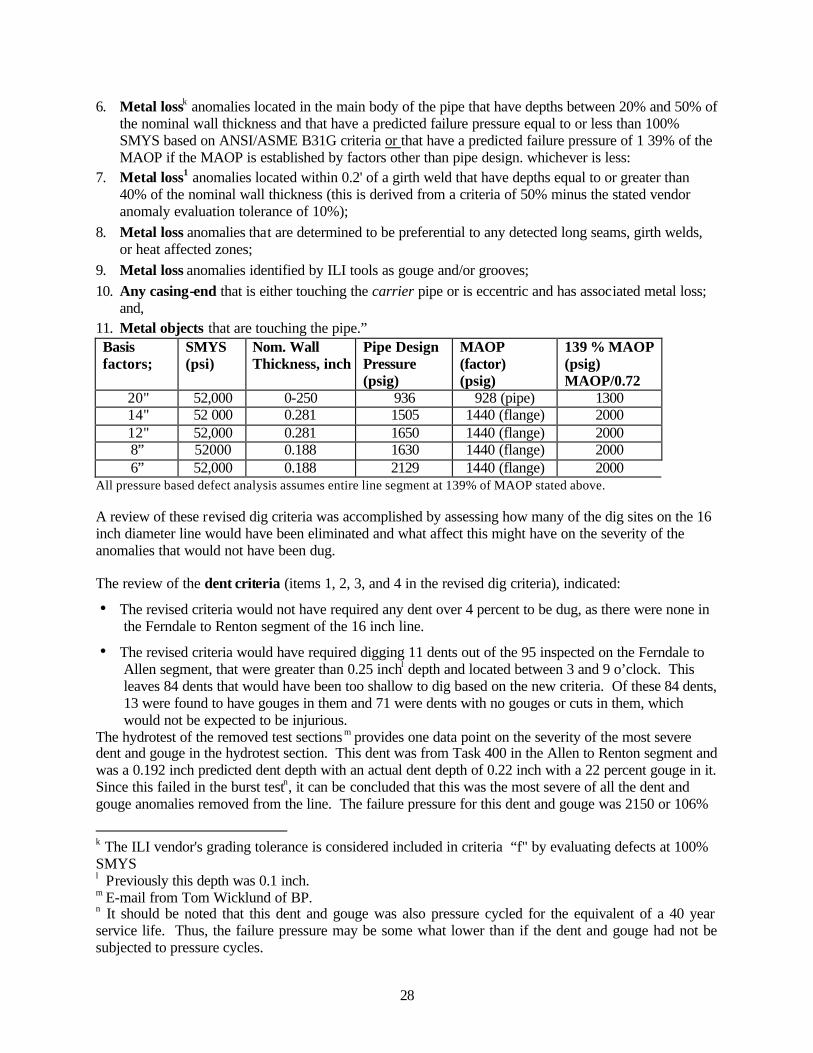
28
6. Metal lossk anomalies located in the main body of the pipe that have depths between 20% and 50% of the nominal wall thickness and that have a predicted failure pressure equal to or less than 100% SMYS based on ANSI/ASME B31G criteria or that have a predicted failure pressure of 1 39% of the MAOP if the MAOP is established by factors other than pipe design. whichever is less:
7. Metal loss1 anomalies located within 0.2' of a girth weld that have depths equal to or greater than 40% of the nominal wall thickness (this is derived from a criteria of 50% minus the stated vendor anomaly evaluation tolerance of 10%);
8. Metal loss anomalies that are determined to be preferential to any detected long seams, girth welds, or heat affected zones;
9. Metal loss anomalies identified by ILI tools as gouge and/or grooves; 10. Any casing-end that is either touching the carrier pipe or is eccentric and has associated metal loss;
and, 11. Metal objects that are touching the pipe.” Basis factors;
SMYS (psi)
Nom. Wall Thickness, inch
Pipe Design Pressure (psig)
MAOP (factor) (psig)
139 % MAOP (psig) MAOP/0.72
20" 52,000 0-250 936 928 (pipe) 1300 14" 52 000 0.281 1505 1440 (flange) 2000 12" 52,000 0.281 1650 1440 (flange) 2000 8” 52000 0.188 1630 1440 (flange) 2000 6” 52,000 0.188 2129 1440 (flange) 2000
All pressure based defect analysis assumes entire line segment at 139% of MAOP stated above. A review of these revised dig criteria was accomplished by assessing how many of the dig sites on the 16 inch diameter line would have been eliminated and what affect this might have on the severity of the anomalies that would not have been dug. The review of the dent criteria (items 1, 2, 3, and 4 in the revised dig criteria), indicated:
• The revised criteria would not have required any dent over 4 percent to be dug, as there were none in the Ferndale to Renton segment of the 16 inch line.
• The revised criteria would have required digging 11 dents out of the 95 inspected on the Ferndale to Allen segment, that were greater than 0.25 inchl depth and located between 3 and 9 o’clock. This leaves 84 dents that would have been too shallow to dig based on the new criteria. Of these 84 dents, 13 were found to have gouges in them and 71 were dents with no gouges or cuts in them, which would not be expected to be injurious.
The hydrotest of the removed test sections m provides one data point on the severity of the most severe dent and gouge in the hydrotest section. This dent was from Task 400 in the Allen to Renton segment and was a 0.192 inch predicted dent depth with an actual dent depth of 0.22 inch with a 22 percent gouge in it. Since this failed in the burst testn, it can be concluded that this was the most severe of all the dent and gouge anomalies removed from the line. The failure pressure for this dent and gouge was 2150 or 106%
k The ILI vendor's grading tolerance is considered included in criteria “f" by evaluating defects at 100% SMYS l Previously this depth was 0.1 inch. m E-mail from Tom Wicklund of BP. n It should be noted that this dent and gouge was also pressure cycled for the equivalent of a 40 year service life. Thus, the failure pressure may be some what lower than if the dent and gouge had not be subjected to pressure cycles.
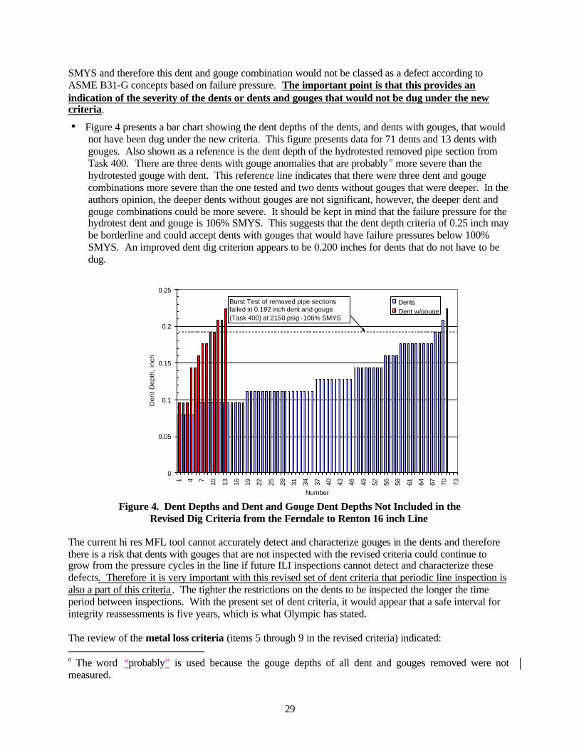
29
SMYS and therefore this dent and gouge combination would not be classed as a defect according to ASME B31-G concepts based on failure pressure. The important point is that this provides an indication of the severity of the dents or dents and gouges that would not be dug under the new criteria.
• Figure 4 presents a bar chart showing the dent depths of the dents, and dents with gouges, that would not have been dug under the new criteria. This figure presents data for 71 dents and 13 dents with gouges. Also shown as a reference is the dent depth of the hydrotested removed pipe section from Task 400. There are three dents with gouge anomalies that are probably o more severe than the hydrotested gouge with dent. This reference line indicates that there were three dent and gouge combinations more severe than the one tested and two dents without gouges that were deeper. In the authors opinion, the deeper dents without gouges are not significant, however, the deeper dent and gouge combinations could be more severe. It should be kept in mind that the failure pressure for the hydrotest dent and gouge is 106% SMYS. This suggests that the dent depth criteria of 0.25 inch may be borderline and could accept dents with gouges that would have failure pressures below 100% SMYS. An improved dent dig criterion appears to be 0.200 inches for dents that do not have to be dug.
Figure 4. Dent Depths and Dent and Gouge Dent Depths Not Included in the Revised Dig Criteria from the Ferndale to Renton 16 inch Line
The current hi res MFL tool cannot accurately detect and characterize gouges in the dents and therefore there is a risk that dents with gouges that are not inspected with the revised criteria could continue to grow from the pressure cycles in the line if future ILI inspections cannot detect and characterize these defects. Therefore it is very important with this revised set of dent criteria that periodic line inspection is also a part of this criteria . The tighter the restrictions on the dents to be inspected the longer the time period between inspections. With the present set of dent criteria, it would appear that a safe interval for integrity reassessments is five years, which is what Olympic has stated. The review of the metal loss criteria (items 5 through 9 in the revised criteria) indicated: o The word “probably” is used because the gouge depths of all dent and gouges removed were not measured.
0
0.05
0.1
0.15
0.2
0.25
1 4 7 10 13 16 19 22 25 28 31 34 37 40 43 46 49 52 55 58 61 64 67 70 73
Number
Den
t D
epth
, in
ch
DentsDent w/gouge
Burst Test of removed pipe sections failed in 0.192 inch dent and gouge (Task 400) at 2150 psig -106% SMYS

30
• The revised criteria would have reduced the number of metal loss anomalies examined in the dig program to 10 from the 19 examined with the original criteria for the 16 inch line from Ferndale to Renton. Of the 10 to be examined under the revised criteria, 6 were greater than 40 percent of the wall thickness in depth and 4 were 20 to 40% of the wall thickness in depth.
• To assess the severity of the 9 anomalies that would be excluded from digging, the calculated failure pressures were compared to the SMYS in Figure 5. All nine of the calculated failure pressures are above 100% SMYS and therefore the revised dig criteria with regard to metal loss appear to be appropriate.
• This result is also reasonable since the corrosion allowed to remain in the line would be shallow and periodic 5 year inspections to be performed on the line will monitor the metal loss in these areas.
Figure 5. Metal Loss Anomaly Calculated Failure Pressures for Metal Loss Anomalies That Would Not be Dug Under the New Dig Criteria
CONCLUSIONS This analysis was conducted to determine if the actions taken by Olympic Pipeline are leading to a pipeline that will be safe for the public. The assessment contained in this report addressed only the 16 inch diameter Ferndale to Renton line segment. The results indicate that the Corrective Action Orders issued by the OPS have provided restrictive criteria for assessing the in line inspection tool log and the dig criteria for this line segment. They have required removing many anomalies from the pipeline that would not be considered as defects. They have also required the removal of several defects that were detected. Finally, they have assisted in reducing the likelihood of incidents from the “other” category of causes and from problems due to operator controls and malfunction of control and pressure relief equipment. The analysis of the in line inspection tool results indicates that there were 128 indications obtained from the in line inspection log. Nine of these were taps that were not correctly identified in grading the log. Three were anomalies that will be removed when the pipe is replaced or rerouted (one was in a river crossing and the permitting is holding up the replacement). Seventy two of the indications were dents,
0
10000
20000
30000
40000
50000
60000
0 0.5 1 1.5 2 2.5 3Metal Loss Length, inch
Cal
cual
ted
Fai
lure
Str
ess,
psi
SMYS

31
metal loss, gouges and a lamination that were cut out and the pipe replaced. Similarly 32 dents and metal loss anomalies were repaired with clocksprings (a fiberglass sleeve wrapped around the pipe). Finally eleven did not require repair and were removed by grinding and recoating of the pipe. This inspection provides assurance that no outside force, corrosion, or manufacturing defects were present when the digs and repairs were completed. The inspection performed on the line was not capable of detecting anomalies in the ERW seam and therefore the 16 inch line was hydrotested. Two test failures occurred at stresses well below SMYS. One in a Lone Star low frequency ERW seam in the Ferndale to Allen segment and the other in a US Steel high frequency ERW seam in the Allen to Renton segment. These failures indicate that inspection of the weld seam was necessary along with the use of the deformation and high res MFL inspection tool in order to achieve a satisfactory integrity assessment of the pipe. It is hoped that a new tool, the axial flux or TFI MFL tool will have the capability to inspect the seam for anomalies and then hydrostatic testing will not be necessary. In line inspection actually offers an improved inspection because it can detect developing integrity defects as well as those severe enough to cause failure in a pressure test. The revised dig criteria for dents appear to be slightly non-conservative. The dig criteria for top of pipe dent depths should be revised to 0.20 inch from the present 0.25 inch dent depth on the top of the pipe. Based on the review, it appears to the author that the 16 inch line segment could have the operating pressure increased to 100 percent of the MOP assuming that the line from an operational viewpoint is not subjected to a large number of pressure cycles due to relief valves operating improperly or for other operational factors. According to Olympic, the pressure will not be increased until the end of 2002 when they expect to have run the TFI tool on the 16 inch line, dug the anomalies, and repaired any defects. The take over of this line by BP has significantly improved the integrity assessment that has been applied to this pipeline. They are doing what is needed to be done. Whether that is because of the external reviews being conducted or their own desire to assure the public of the pipelines’ integrity is unknown but the author believes that it is because of their desire to operate the line in a safe manner.
REFERENCES 1 Testimony of Jim Hall, Chairman NTSB before the Committee on Transportation and Infrastructure subcommittee on Economic Development, Public Buildings, Hazardous Material, and Pipeline Transportation, House of Representatives, October 27, 1999, www.ntsb.gov/speeches/jhc991027.htm. 2 Thompson, S., One Year Later, the planet, spring/summer 2000, Huxley College , Western Washington University, Bellingham, WA. 3 Office of Pipeline Safety, Liquid Pipeline Accident Database available from the www.ops.dot.gov, pipeline statistics, 2001. 4 Eiber, R., Bubenik, T. and Maxey, W., Fracture Control Technology for Natural Gas Pipelines, Pipeline Research Committee Report NG-18 Report 208, Project PR 3-9113, December 1993.


![Enhanced Pipeline Risk Assessment Pipeline Risk Assessment Part 1, Rev 2.1 – May 2006 . 2. 12)] failure ….. )] )] … Type = (TTF) ) ...](https://static.fdocuments.in/doc/165x107/5ad5d3317f8b9a075a8d6596/enhanced-pipeline-risk-pipeline-risk-assessment-part-1-rev-21-may-2006-2.jpg)
