![Report on Proposals F2006 — Copyright, NFPA NFPA 25 · 2016-04-05 · Clement J. Adams, Chubb Group of Insurance Companies, PA [I] Gary S. Andress, Liberty Mutual Property, MA [I]](https://static.fdocuments.in/doc/165x107/5ea1ef2964dec6072e12aded/report-on-proposals-f2006-a-copyright-nfpa-nfpa-25-2016-04-05-clement-j-adams.jpg)
Report on Comments F2006 — Copyright, NFPA NFPA 1911
28
1911-1 Report on Comments F2006 — Copyright, NFPA NFPA 1911 Report of the Committee on Fire Department Apparatus Jeffrey Bowman, Chair San Diego Fire Department, CA [U] Kenneth L. Koch, Secretary Sutphen Corporation, OH [M] William M. Ballantyne, Hypro LLC, MN [M] Rep. Fire Apparatus Manufacturers Association Robert J. Barraclough, Plano, TX [SE] Peter F. Darley, W. S. Darley & Company, IL [M] Rep. National Truck Equipment Association Ralph Dorio, Insurance Services Office, NJ [I] Donald L. Frazeur, Los Angeles Fire Department, CA [U] Gordon L. Gholson, State of California, CA [U] Gary Handwerk, Hale Products Incorporated, FL [M] Tom Hillenbrand, Underwriters Laboratories Incorporated, IL [RT] James J. Juneau, Juneau, Boll & Ward, P.L.L.C., TX [SE] James L. Kelker, National Testing/Conam Inspection Incorporated, OH [RT] J. Roger Lackore, Pierce Manufacturing Incorporated, WI [M] William McCombs, Emergency One, Incorporated, FL [M] John W. McDonald, US General Services Administration, VA [E] Dan W. McKenzie, US Department of Agriculture, CA [RT] W. Kenneth Menke, Fire Service Research Institute, MO [SE] J. Allen Metheny, Sr., Hartly Volunteer Fire Company, DE [U] Rep. National Volunteer Fire Council Tom Mettler, Waterous Company, MN [M] Jeff Piechura, Northwest Fire District, AZ [U] Gary R. Pope, Fairfax County Fire & Rescue Department, VA [U] James A. Salmi, Crimson Fire, PA [M] Alan Saulsbury, Fire Spec Services, Incorporated, NY [SE] Thomas A. Stalnaker, Goshen Fire Company, PA [U] John M. Terefinko, KME Fire Apparatus, PA [M] Robert D. Tutterow, Jr., Charlotte Fire Department, NC [U] William von Zehle, Jr., Ridgefield, CT [U] Rep. International Association of Fire Chiefs David White, Fire & Safety Specialists, Incorporated, TX [SE] Alternates Robert T. Bettenhausen, Tinley Park Volunteer Fire Department, IL [U] (Alt. to William von Zehle, Jr.) James T. Currin, KME Fire Apparatus, VA [M] (Alt. to John M. Terefinko) Andrew L. Duke, Fairfax County Fire & Rescue Department, VA [U] (Alt. to Gary R. Pope) Ronald L. Ewers, Class I, FL [M] (Alt. to Gary Handwerk) David V. Haston, US Department of Agriculture, CA [RT] (Alt. to Dan W. McKenzie) James Johannessen, Underwriters Laboratories Incorporated, PA [RT] (Alt. to Tom Hillenbrand) Brad C. Kobielusz, Poudre Fire Authority, CO [U] (Alt. to Robert D. Tutterow, Jr.) Madhu Manikkam, Emergency One, Incorporated, FL [M] (Alt. to William McCombs) Thomas H. McCullough, II, VFIS Claims Management, Incorporated, PA [I] (Voting Alt. to VFIS Rep.) Michael R. Moore, Pierce Manufacturing Incorporated, WI [M] (Alt. to J. Roger Lackore) W. Michael Pietsch, Mike Pietsch, P.E. Consulting Services, Incorporated, TX [SE] (Alt. to David White) Michael C. Ruthy, W. S. Darley & Company, WI [M] (Alt. to Peter F. Darley) Thomas G. Stites, Sutphen Corporation, OH [M] (Alt. to Kenneth L. Koch) Edward F. Straw, Insurance Services Office, Incorporated, GA [I] (Alt. to Ralph Dorio) Robert F. Stroud, US Department of the Interior, ID [U] (Alt. to Gordon L. Gholson) Phillip L. Turner, Super Vacuum Manufacturing Company, Incorporated, CO [M] (Alt. to William M. Ballantyne) Dean David Ulrich, Los Angeles City Fire Department, CA [U] (Alt. to Donald L. Frazeur) Nonvoting Howard L. McMillen, Fort Worth, TX (Member Emeritus) Staff Liaison: Carl E. Peterson Committee Scope: This Committee shall have primary responsibility for documents on the design and performance of fire apparatus for use by the fire service. This list represents the membership at the time the Committee was balloted on the text of this edition. Since that time, changes in the membership may have occurred. A key to classifications is found at the front of this book. This portion of the Technical Committee Report of the Committee on Fire Department Apparatus is presented for adoption. This Report on Comments was prepared by the Technical Committee on Fire Department Apparatus, and documents its action on the comments received on its Report on Proposals on NFPA 1911, Standard for Service Tests of Fire Pump Systems on Fire Apparatus, 2002 edition, as published in the Report on Proposals for the 2006 Fall Meeting. This Report on Comments has been submitted to letter ballot of the Technical Committee on Fire Department Apparatus, which consists of 29 voting members. The results of the balloting, after circulation of any negative votes, can be found in the report.
Transcript of Report on Comments F2006 — Copyright, NFPA NFPA 1911
1911-1
Report on Comments F2006 — Copyright, NFPA NFPA 1911Report of the Committee on
Fire Department Apparatus
Jeffrey Bowman, ChairSan Diego Fire Department, CA [U]
Kenneth L. Koch, SecretarySutphen Corporation, OH [M]
William M. Ballantyne, Hypro LLC, MN [M] Rep. Fire Apparatus Manufacturers Association Robert J. Barraclough, Plano, TX [SE] Peter F. Darley, W. S. Darley & Company, IL [M] Rep. National Truck Equipment Association Ralph Dorio, Insurance Services Office, NJ [I] Donald L. Frazeur, Los Angeles Fire Department, CA [U] Gordon L. Gholson, State of California, CA [U] Gary Handwerk, Hale Products Incorporated, FL [M] Tom Hillenbrand, Underwriters Laboratories Incorporated, IL [RT] James J. Juneau, Juneau, Boll & Ward, P.L.L.C., TX [SE] James L. Kelker, National Testing/Conam Inspection Incorporated, OH [RT] J. Roger Lackore, Pierce Manufacturing Incorporated, WI [M] William McCombs, Emergency One, Incorporated, FL [M]John W. McDonald, US General Services Administration, VA [E]Dan W. McKenzie, US Department of Agriculture, CA [RT]W. Kenneth Menke, Fire Service Research Institute, MO [SE]J. Allen Metheny, Sr., Hartly Volunteer Fire Company, DE [U] Rep. National Volunteer Fire Council Tom Mettler, Waterous Company, MN [M] Jeff Piechura, Northwest Fire District, AZ [U] Gary R. Pope, Fairfax County Fire & Rescue Department, VA [U] James A. Salmi, Crimson Fire, PA [M] Alan Saulsbury, Fire Spec Services, Incorporated, NY [SE] Thomas A. Stalnaker, Goshen Fire Company, PA [U] John M. Terefinko, KME Fire Apparatus, PA [M] Robert D. Tutterow, Jr., Charlotte Fire Department, NC [U] William von Zehle, Jr., Ridgefield, CT [U] Rep. International Association of Fire Chiefs David White, Fire & Safety Specialists, Incorporated, TX [SE]
Alternates
Robert T. Bettenhausen, Tinley Park Volunteer Fire Department, IL [U] (Alt. to William von Zehle, Jr.) James T. Currin, KME Fire Apparatus, VA [M] (Alt. to John M. Terefinko) Andrew L. Duke, Fairfax County Fire & Rescue Department, VA [U] (Alt. to Gary R. Pope) Ronald L. Ewers, Class I, FL [M] (Alt. to Gary Handwerk) David V. Haston, US Department of Agriculture, CA [RT] (Alt. to Dan W. McKenzie) James Johannessen, Underwriters Laboratories Incorporated, PA [RT] (Alt. to Tom Hillenbrand)
Brad C. Kobielusz, Poudre Fire Authority, CO [U] (Alt. to Robert D. Tutterow, Jr.) Madhu Manikkam, Emergency One, Incorporated, FL [M] (Alt. to William McCombs) Thomas H. McCullough, II, VFIS Claims Management, Incorporated, PA [I] (Voting Alt. to VFIS Rep.) Michael R. Moore, Pierce Manufacturing Incorporated, WI [M] (Alt. to J. Roger Lackore) W. Michael Pietsch, Mike Pietsch, P.E. Consulting Services, Incorporated, TX [SE] (Alt. to David White) Michael C. Ruthy, W. S. Darley & Company, WI [M] (Alt. to Peter F. Darley) Thomas G. Stites, Sutphen Corporation, OH [M] (Alt. to Kenneth L. Koch) Edward F. Straw, Insurance Services Office, Incorporated, GA [I] (Alt. to Ralph Dorio) Robert F. Stroud, US Department of the Interior, ID [U] (Alt. to Gordon L. Gholson) Phillip L. Turner, Super Vacuum Manufacturing Company, Incorporated, CO [M] (Alt. to William M. Ballantyne) Dean David Ulrich, Los Angeles City Fire Department, CA [U] (Alt. to Donald L. Frazeur)
Nonvoting
Howard L. McMillen, Fort Worth, TX (Member Emeritus)
Staff Liaison: Carl E. Peterson
Committee Scope: This Committee shall have primary responsibility for documents on the design and performance of fire apparatus for use by the fire service.
This list represents the membership at the time the Committee was balloted on the text of this edition. Since that time, changes in the membership may have occurred. A key to classifications is found at the front of this book.
This portion of the Technical Committee Report of the Committee on Fire Department Apparatus is presented for adoption.
This Report on Comments was prepared by the Technical Committee on Fire Department Apparatus, and documents its action on the comments received on its Report on Proposals on NFPA 1911, Standard for Service Tests of Fire Pump Systems on Fire Apparatus, 2002 edition, as published in the Report on Proposals for the 2006 Fall Meeting.
This Report on Comments has been submitted to letter ballot of the Technical Committee on Fire Department Apparatus, which consists of 29 voting members. The results of the balloting, after circulation of any negative votes, can be found in the report.

1911-2
Report on Comments F2006 — Copyright, NFPA NFPA 1911____________________________________________________________1911-1 Log #64 Final Action: Accept in Part(2.3.3)____________________________________________________________Submitter: James E. Glatts, FireOneComment on Proposal No: 1911-1Recommendation: Delete: ASTM B 647 ASTM B 648 ASTM E 10 ASTM E 18 ASTM E 92 ASTM E 1032 Keep the rest of the ASTM publications in the section.Substantiation: Hardness testing does not always give an accurate reading using a hand held impressor. The hardness test is mute if an aerial device passed its load and operational test. Radiographic examinations are not economically feasible.Committee Meeting Action: Accept in Part Delete the reference to ASTM 1032.Committee Statement: The committee is not deleting the hardness testing which the other listed ASTM standard apply to. It is deleting references to radiographic inspection so ASTM 1032 can be deleted. Number Eligible to Vote: 29Ballot Results: Affirmative: 26 Ballot Not Returned: 3 Hillenbrand, T., Pope, G., von Zehle, Jr., W.
____________________________________________________________1911-2 Log #5 Final Action: Accept in Principle(3.3.26 Combination Vehicle)____________________________________________________________Submitter: Thomas A. Stalnaker, Goshen Fire CompanyComment on Proposal No: 1911-1Recommendation: Revise the definition to read as follows: 3.3.26 Combination Vehicle. A vehicle consisting of a pulling tractor towing vehicle and trailer. [1901:2003]Substantiation: The term Combination Vehicle applies to both a tractor-trailer vehicle (ladder or rescue truck) and a straight truck pulling a boat trailer, trench rescue equipment trailer, or any trailer that might be towed. This term is used in conjunction with GCWR, which applies in all these cases. Committee Meeting Action: Accept in PrincipleRevise the definition to read: Combination Vehicle. A vehicle consisting of a pulling tractor and trailer towing vehicle and one or more towed units.Committee Statement: The revised definition takes into account that there could be more than one towed unit. Number Eligible to Vote: 29Ballot Results: Affirmative: 26 Ballot Not Returned: 3 Hillenbrand, T., Pope, G., von Zehle, Jr., W.
____________________________________________________________1911-3 Log #6 Final Action: Accept(3.3.47 Extension Indicator)____________________________________________________________Submitter: Thomas A. Stalnaker, Goshen Fire CompanyComment on Proposal No: 1911-1Recommendation: Revise the definition to read as follows: 3.3.47 Extension Indicator. A device on an aerial ladder or extensible boom aerial device that indicates the number of feet (meters) that the device has been extended.Substantiation: In applications outside of the United States, this measurement would be in meters, not feet. This format is followed throughout the rest of the document.Committee Meeting Action: AcceptNumber Eligible to Vote: 29Ballot Results: Affirmative: 26 Ballot Not Returned: 3 Hillenbrand, T., Pope, G., von Zehle, Jr., W.
____________________________________________________________1911-4 Log #7 Final Action: Accept(3.3.89 Out-of-Service)____________________________________________________________Submitter: Thomas A. Stalnaker, Goshen Fire CompanyComment on Proposal No: 1911-1Recommendation: Revise the definition to read as follows: 3.3.89 Out-of-Service. The condition when an apparatus or component is not useable due to an unsafe or inoperable condition.Substantiation: The term is used in Chapter 6 to refer to either the entire apparatus or a component or portion of the apparatus.Committee Meeting Action: AcceptNumber Eligible to Vote: 29Ballot Results: Affirmative: 26 Ballot Not Returned: 3 Hillenbrand, T., Pope, G., von Zehle, Jr., W.
____________________________________________________________1911-5 Log #63 Final Action: Accept(3.3.101 Radiographic Inspection)____________________________________________________________Submitter: James E. Glatts, FireOneComment on Proposal No: 1911-1Recommendation: Delete entire section. Radiographic Inspection. A nondestructive...Substantiation: The cost to complete a radiographic inspection of an aerial device costs more than the valve of a ladder truck. Radiographic inspections of aerial devices just is not done and should be deleted from the standard.Committee Meeting Action: AcceptNumber Eligible to Vote: 29Ballot Results: Affirmative: 26 Ballot Not Returned: 3 Hillenbrand, T., Pope, G., von Zehle, Jr., W.
____________________________________________________________1911-6 Log #40 Final Action: Reject(4.3.1.3 (New) )____________________________________________________________Submitter: Tom Hillenbrand, Underwriters Laboratories Inc.Comment on Proposal No: 1911-1Recommendation: Add new text to read: If a third-party test company is employed to conduct performance testing, that company shall meet the requirements of ISO/IEC 17020, General criteria for the operation of various types of bodies performing inspection.Substantiation: Chapter 19, Section 19.3 requires third-party test companies performing NDT for aerial devices to meet ISO/IEC 17020. Third-party test companies should also meet ISO/IEC 17020 when performing other performance tests (i.e., pump tests, low-voltage tests, etc.)Committee Meeting Action: RejectCommittee Statement: This requirement would eliminate third party companies from completing annual performance testing.Number Eligible to Vote: 29Ballot Results: Affirmative: 26 Ballot Not Returned: 3 Hillenbrand, T., Pope, G., von Zehle, Jr., W.
____________________________________________________________1911-7 Log #8 Final Action: Accept in Principle(6.7.1(1))____________________________________________________________Submitter: Thomas A. Stalnaker, Goshen Fire CompanyComment on Proposal No: 1911-1Recommendation: Revise text to read as follows: 6.7.1(1) Legally required lighting or horn is non-operational (DOT lighting) and hornsSubstantiation: The grammar was incorrect. The lighting can be non-operational but the lighting is not a horn, which was what the statement said. Either the lighting or the horn can be non-operational.Committee Meeting Action: Accept in Principle Revise 6.7.1(1) to read as follows: Legally required lighting (DOT lighting) or horn is non-operational (DOT lighting) and horns.Committee Statement: The committee is further revising the text for clarification of the intent.Number Eligible to Vote: 29Ballot Results: Affirmative: 26 Ballot Not Returned: 3 Hillenbrand, T., Pope, G., von Zehle, Jr., W.
____________________________________________________________1911-8 Log #9 Final Action: Accept(6.7.3(4) and (5) (New) )____________________________________________________________Submitter: Thomas A. Stalnaker, Goshen Fire CompanyComment on Proposal No: 1911-1Recommendation: Add new subsections to read as follows: (4) Line Voltage power source producing high or low voltage or frequency (5) Damaged receptacles or observed electrical shock hazard Substantiation: These additional conditions should be evaluated to determine if the line voltage system, or some part of it, should be placed out-of-service until the condition is repaired.Committee Meeting Action: AcceptNumber Eligible to Vote: 29Ballot Results: Affirmative: 26 Ballot Not Returned: 3 Hillenbrand, T., Pope, G., von Zehle, Jr., W.

1911-3
Report on Comments F2006 — Copyright, NFPA NFPA 1911____________________________________________________________1911-9 Log #55 Final Action: Accept in Principle(6.8.4 (New) )____________________________________________________________Submitter: Dan McKenzie, USDA Forest ServiceComment on Proposal No: 1911-1Recommendation: Add new text to read as follows: 6.8.4 Wheel Chocks. Verify that the apparatus is equipped with two wheel chocks, mounted in readily accessible locations, each capable of holding the fully loaded apparatus on a 10 percent grade with the transmission in neutral and parking brake released.Substantiation: NFPA 1901 requires that the apparatus be equipped with “Two wheel chocks mounted in readily accessible locations, each designed to hold the apparatus, when loaded to its maximum in-service weight, on a 10 percent grade with the transmission in neutral and the parking brake released.”Committee Meeting Action: Accept in Principle Add a new 6.8.4 to read: Wheel Chocks. Verify that the apparatus is equipped with two wheel chocks, mounted in readily accessible locations.Committee Statement: The committee does not want performance requirements for wheel chocks in a maintenance standard. Number Eligible to Vote: 29Ballot Results: Affirmative: 26 Ballot Not Returned: 3 Hillenbrand, T., Pope, G., von Zehle, Jr., W.
____________________________________________________________1911-10 Log #11 Final Action: Accept(7.12.10.1)____________________________________________________________Submitter: Thomas A. Stalnaker, Goshen Fire CompanyComment on Proposal No: 1911-1Recommendation: Revise text to read as follows: 7.12.10.1 If air accessories are connected to the chassis air brake system, the requirements of 7.12.10.1.1 through 7.12.10.1.2 shall apply. 7.12.10.1.1 The air Air brake system pressure protection valve(s) shall be diagnostically checked to the shutoff point. 7.12.10.1.12 If air accessories are connected to the chassis air brake system, the The pressure protection valve shall prevent the air accessories from drawing air from the air brake system when the air pressure drops below 80 psi (552 kPa) to ensure adequate air pressure for the braking system.Substantiation: The Manual of Style July 2004 edition section 1.8.1 does not allow a.1 subdivision without a.2 subdivision. This change is in format only, no change to requirements.Committee Meeting Action: AcceptNumber Eligible to Vote: 29Ballot Results: Affirmative: 26 Ballot Not Returned: 3 Hillenbrand, T., Pope, G., von Zehle, Jr., W.
____________________________________________________________1911-11 Log #12 Final Action: Accept in Principle(7.12.10.9 and 7.12.10.10)____________________________________________________________Submitter: Thomas A. Stalnaker, Goshen Fire CompanyComment on Proposal No: 1911-1Recommendation: Revise text to read as follows: 7.12.10.9 Leak-down rate (time) of the applied side and the supply-side of the air-brake system shall each be tested. 7.12.10.9.1 An air pressure drop of more than 3 psi (20.7 kPa) in 1 minute for single fire apparatus or more than 4 psi (27.6 kPa) in 1 minute for combination fire apparatus, with the engine stopped and the service brakes applied, shall be considered unacceptable. 7.12.10.10 Leak-down rate (time) of the supply-side of the chassis air system shall be tested. 7.12.10.10.19.2 An air pressure drop of more than 2 psi (13.8 kPa) in 1 minute for single fire apparatus or more than 3 psi (20.7 kPa) in 1 minute for combination fire apparatus, with the engine stopped and the service brakes released, shall be considered unacceptable.Substantiation: The Manual of Style July 2004 edition section 1.8.1 does not allow a.1 subdivision without a.2 subdivision. This change is in format only, no change to requirements.Committee Meeting Action: Accept in Principle Revise 7.12.10.9 to read as follows: 7.12.10.9 Leak-down rate (time) of the applied side of the air-brake system shall be tested with the engine stopped and the service brakes applied, and the air pressure shall not drop more than 3 psi (20.7 kPa) in 1 minute for a straight vehicle single fire apparatus or more than 4 psi (27.6 kPa) in 1 minute for combination vehicle fire apparatus. Revise 7.12.10.10 to read as follows: 7.12.10.10 Leak-down rate (time) of the supply-side of the chassis air system shall be tested with the engine stopped and the service brakes released, and the air pressure shall not drop more than 2 psi (13.8 kPa) in 1 minute for a straight vehicle single fire apparatus or more than 3 psi (20.7 kPa) in 1 minute for combination vehicle fire apparatus.
Committee Statement: The committee has changed the term “fire apparatus” to “vehicle” and the term “single” to “straight” for editorial clarification but is leaving everything else as published in the ROP. The submitter’s concerns were addressed before the draft was published in the ROP.Number Eligible to Vote: 29Ballot Results: Affirmative: 26 Ballot Not Returned: 3 Hillenbrand, T., Pope, G., von Zehle, Jr., W.
____________________________________________________________1911-12 Log #48 Final Action: Accept in Principle(Chapter 8)____________________________________________________________Submitter: Lisa Breu, Oshkosh Truck CorporationComment on Proposal No: 1911-1Recommendation: Add new text to read: Wiring. All wiring and wire looms shall be inspected for security of mounting, proper routing, presence of grommets, condition and cleanliness.Substantiation: This is in the line-voltage section and also applies to the low-voltage wiring.Committee Meeting Action: Accept in Principle Add a new Section 8.3 to read as follows: Wiring. All wiring and wire looms shall be inspected for security of mounting, tight connections, proper routing, grommets in place, condition, and cleanliness. Renumber from current Section 8.3 going forward.Committee Statement: The committee is indicating where to add the wording and is using the same wording as is used in Section 13.3 on line voltage including the change being accepted by action on public Comment 1911-13 (Log #46).Number Eligible to Vote: 29Ballot Results: Affirmative: 26 Ballot Not Returned: 3 Hillenbrand, T., Pope, G., von Zehle, Jr., W.
____________________________________________________________1911-13 Log #46 Final Action: Accept(13.3 (New) )____________________________________________________________Submitter: Lisa Breu, Oshkosh Truck CorporationComment on Proposal No: 1911-1Recommendation: Revise as follows: “...security of mounting, tight connections, proper routing...”Substantiation: Checking low-volt connections is covered in 8.1.2(4) checking for excessive heating (one to loose connections) is covered in 13.4.3 and A.13.4.3 addressing this directly in the wiring section specifically instructs the tester to check the line-volt connections. Otherwise it may be missed/skipped or they may not realize connections should be checked.Committee Meeting Action: AcceptNumber Eligible to Vote: 29Ballot Results: Affirmative: 26 Ballot Not Returned: 3 Hillenbrand, T., Pope, G., von Zehle, Jr., W.
____________________________________________________________1911-14 Log #13 Final Action: Accept in Principle(13.4, 13.6, 22.3, 22.4, 22.5, and 22.6)____________________________________________________________Submitter: Thomas A. Stalnaker, Goshen Fire CompanyComment on Proposal No: 1911-1Recommendation: Revise text to read as follows: 13.4 Appliances and Controls. 13.4.1 All line voltage appliances and controls, including but not limited to the following appliances and controls, shall be inspected for security of mounting and condition. (1) Cord reels (2) Extension cords (3) Scene lights (4) Switches (5) Relays (6) Receptacles (7) Inlet devices (8) Light towers (9) Any other line voltage devices not listed 13.4.2* All line voltage equipment on the apparatus shall be diagnostically checked for a minimum of 10 minutes. A.13.4.2 This testing may be performed at the same time as the power source load testing in 21.4, or may be performed separately. 13.4.3* All equipment must operate properly without arching, failure, or excessive heating. A.13.4.3 Heating of plugs, receptacles, and other points of connection are indications of loose connections. All these points should be checked after at least 5 minutes of time under load. Any devices with hot connectors should be removed from service until repaired.

1911-4
Report on Comments F2006 — Copyright, NFPA NFPA 1911 13.5 Receptacle Wiring. All 120 volt receptacles shall be diagnostically checked for the polarity of the wiring and the ground continuity, including receptacles on the body, cord reels, and aerial device. 13.5.1* Testing shall be done with a tester that verifies that the wiring of hot and neutral is to the correct receptacle pins, and verifies that the ground is connected. A.13.5.1 Inexpensive receptacle testers with lights to indicate correct or problem wiring are available from any hardware store or home center. Many also include a button for testing GFCI’s as needed for the testing in 13.6.2(3). Testing of twist lock or other special outlets will require the use of an adapter. 13.5.2 Any receptacles that can be powered both from an on-board power source and from a shore line shall be tested both ways. 13.5.3 Duplex receptacles shall be tested in both receptacle. 13.6 Circuit Protection. 13.6.1 Circuit breakers and Ground Fault Circuit Interrupters (GFCIs) shall be inspected for condition and diagnostically checked. 13.6.2 All circuit breakers and Ground Fault Circuit Interrupters (GFCIs) shall be cycled off and on. 13.6.2 If the apparatus is equipped with Ground Fault Circuit Interrupters (GFCIs) they shall be inspected for mounting and condition. 13.6.3 If the apparatus, or any appliances incorporate ground fault circuit interrupters (GFCIs), they shall be diagnostically checked to determine the following: (1) The integrated test button trips the GFCI. (2) The reset button restores the GFCI. (3)* The GFCI trips when a ground fault is simulated with an external tester. A.13.6.3(3) Inexpensive receptacle testers with a GFCI test button and lights to indicate correct or problem wiring are available from any hardware store or home center. This same tester can be used for the receptacle testing required in 13.5. Testing of twist lock or other special outlets will require the use of an adapter.
Add new requirements after Section 22.2 to read as follows: 22.3 Power Source Testing. 22.3.1 The line voltage power source shall be tested annually except when the Full Load Test in Section 22.7 is performed. 22.3.2 The power source shall be tested using loads normally carried on the apparatus. All available loads shall be run simultaneously up to the limit in 22.3.3. 22.3.3 The total load applied shall not exceed the continuous rating as specified on the power source specification label, or power source nameplate if there is no power source specification label. 22.3.4 The power source shall be run for a minimum of 10 minutes under load. 22.3.5 The voltage, frequency, and load shall be measured and recorded: (1) At no load at the beginning of the test (2) After the test load has been applied (3) After 10 minutes under load (4) After load has been removed at the end of the test 22.3.6 The voltage and frequency shall be within the limits specified by NFPA 1901 at the time the apparatus was built. 22.4 Receptacle Wiring. 22.4.1 The polarity of the wiring and the ground continuity of all 120 volt outlets shall be tested, including outlets on the body, cord reels, and aerial device. 22.4.2* Testing shall be done with a tester that verifies that the wiring of Hot and Neutral is to the correct receptacle pins, and verifies that the ground is connected. A.22.4.2 Inexpensive receptacle testers with lights to indicate correct or problem wiring are available from any hardware store or home center. Many also include a button for testing GFCI’s as needed for the testing in Section 22.6. Testing can also be done with the power off using a continuity tester to the hot and neutral busses in the circuit breaker panel for the hot and neutral wires and to the body for the protective ground wire. Testing of twist lock or other special outlets may require the use of an adapter. 22.4.3 Any outlet that can be powered both from an on-board power source and from a shore line shall be tested both ways. 22.4.4 Duplex receptacles shall be tested in both receptacles. 22.5 GFCI Testing. 22.5.1 If the apparatus, or any appliances, incorporate Ground Fault Circuit Interrupters (GFCIs), they shall be checked in accordance with this section. 22.5.2 All GFCIs shall be checked, whether integrated into outlets or circuit breakers, or they are separate devices. 22.5.3 The check shall verify that the integrated test button trips the GFCI. 22.5.4 The check shall verify that the reset button restores the GFCI. 22.5.5* The check shall verify that the GFCI trips when a ground fault is simulated with an external tester. A.22.5.5 Inexpensive receptacle testers with a GFCI test button and lights to indicate correct or problem wiring are available from any hardware store or home center. This same tester can be used for the
receptacle testing in Section 21.3. Testing of twist lock or other special outlets may require the use of an adapter. 22.6 Line Voltage Equipment Testing. 22.6.1* All line voltage equipment on the apparatus shall be run for a minimum of 10 minutes. A.22.6.1 This testing may be performed at the same time as the power source testing in Sections 22.3 or 22.7. 22.6.2 The testing shall include, but not be limited to: (1) Light Towers (2) Permanently wired lights (3) Electric motors (4) Fixed wired appliances (5) Outlets, fixed cords, and cord reels (loaded to at least 50 percent of circuit breaker rating) (6) Duplex outlets shall be tested in both outlets 22.6.3* All equipment must operate properly without arching, failure, or excessive heating. A.22.6.3 Heating of plugs, receptacles, and other points of connection are indications of loose connections. All points should be checked after at least 5 minutes of time under load. Any devices with hot connectors should be removed from service until repaired. Renumber existing Sections 22.3 and 22.4 as 22.7 and 22.8. Revise Sections 22.3 and 22.3.1 (to be renumbered Sections 22.7 and 22.7.1) as follows: 22.3 Full Load Test of Power Source. 22.3.1 The full load test of the power source shall be performed at least every 5 years.Substantiation: These tests should be part of the “testing” process, not the “Inspection and Maintenance” process. They were put in the testing chapter by the committee at the Harrisburg meeting and got moved sometime after that. The post-committee editing removed all the annual tests from the line voltage electrical testing section. The new 13.6.2 adds cycling circuit breakers to clean contacts.Committee Meeting Action: Accept in Principle Replace 13.4, 13.5 and 13.6 with the following: 13.4 Appliances and Controls. All line voltage appliances and controls, including but not limited to the following appliances and controls, shall be inspected for security of mounting and condition (1) Cord reels (2) Extension cords (3) Scene lights (4) Circuit breaker box (5) Switches (6) Relays (7) Receptacles (8) Inlet devices (9) Light towers (10) Other line voltage devices not specified in 13.4.1(1) through (9) 13.5 Circuit Protection. 13.5.1 Circuit breakers and ground fault circuit interrupters (GFCIs) shall be inspected for condition and diagnostically checked. 13.5.2 All circuit breakers and ground fault circuit interrupters (GFCIs) shall be cycled off and on. Add a new Section 22.3 to read as follows: 22.3 Power Source Testing. 22.3.1 The line voltage power source shall be tested annually except when the full load test in Section 22.7 is performed. 22.3.2 The power source shall be tested using the electrical loads normally carried on the apparatus connected simultaneously, up to the limit specified in 22.3.3. 22.3.3 The total electrical load applied shall not exceed the continuous rating as specified on the power source specification label, or the power source nameplate rating if there is no power source specification label. 22.3.4 The power source shall be run for a minimum of 10 minutes under the test load specified in 22.3.2. 22.3.5 The voltage, frequency, and load shall be measured and recorded at the following times: (1) At the beginning of the test under no load conditions (2) After the test load has been applied (3) After 10 minutes under test load (4) At the end of the test when the test load has been removed 22.3.6 The voltage and frequency shall be within the limits specified by NFPA 1901 at the time the apparatus was built. Add a new Section 22.4 to read as follows: 22.4 Receptacle Wiring. 22.4.1 The polarity of the wiring, the ground continuity, and the neutral bonding or isolation of all 120 volt outlets shall be tested, including receptacles on the body, cord reels, and aerial device. 22.4.1.1* If the neutral conductor is bonded to the vehicle frame, the testing shall be done with a tester that verifies that the hot and neutral wires are connected to the correct receptacle pins, and verifies that the ground is connected. 22.4.1.2* If the neutral is not bonded to the vehicle frame, the testing shall be done with the power off using a continuity tester or ohmmeter to verify that both of the current carrying conductors are isolated from the

1911-5
Report on Comments F2006 — Copyright, NFPA NFPA 1911vehicle body and frame, and that the protective ground is connected to the vehicle body and frame. 22.4.2* Any receptacle that can be powered both from an on-board power source and from a shore line shall be tested both ways. 22.4.3 Duplex receptacles shall be tested in both receptacles. Add a new Section 22.5 to read as follows: 22.5* GFCI Testing. If the wiring system or any appliances on the apparatus incorporate ground fault circuit interrupters (GFCIs), they shall be operationally checked in accordance with this section. 22.5.1 All GFCIs shall be checked, whether they are integrated into receptacles or circuit breakers, or they are separate devices. 22.5.2 The operational check shall verify the following: (1) That the integrated test button trips the GFCI. (2) That the reset button restores the GFCI. (3) That the GFCI trips when a ground fault is simulated with an external tester. Add a new Section 22.6 to read as follows: 22.6 Line Voltage Equipment Testing. 22.6.1* All line voltage equipment on the apparatus shall be run for a minimum of 10 minutes. 22.6.2 The testing shall include, but not be limited to: (1) Light towers (2) Permanently wired lights (3) Electric motors (4) Fixed wired appliances (5) Receptacles (each individual receptacle if in multiples), fixed cords, and cord reels each loaded to at least 50 percent of the rating of the circuit breaker for that circuit 22.6.3* All equipment shall operate properly without arching, failure, or excessive heating. Renumber existing Sections 22.3 and 22.4 as 22.7 and 22.8. Revise existing Section 22.3 and 22.3.1 (renumbered as Sections 22.7 and 22.7.1) to read as follows: 22.7 Full Load Test of Power Source. 22.7.1 The full load test of the power source shall be performed at least every 5 years. Revise existing 22.4.4 (renumbered as 22.8.4) to read as follows: 22.8.4* The test shall be conducted as follows: (1) If the system has a neutral conductor bonded to the vehicle chassis, isolate the power source from the panel board. (2) Disconnect any solid state low voltage components. (3) Connect one lead of the dielectric tester to all the hot and neutral busses tied together. (4) Connect the other lead to the fire apparatus frame or body. (5) Close any switches and circuit breakers in the circuit(s). (6) Apply the dielectric voltage for 1 minute in accordance with the testing equipment manufacturer’s instructions. Add annex material to the new 22.4.1 to read as follows: A.22.4.1 All loads must be disconnected while doing continuity testing. Add annex material to the new 22.4.1.1 to read as follows: A.22.4.1.1 Inexpensive receptacle testers with lights to indicate correct or problem wiring are available from any hardware store or home center. Many also include a button for testing GFCIs as needed for the testing in 22.5.5. Testing can also be done with the power off using a continuity tester to the hot and neutral busses in the circuit breaker panel for the hot and neutral wires and to the body for the protective ground wire. Testing of twist lock or other special receptacles may require the use of an adapter. Add annex material to the new 22.4.1.2 to read as follows: A.22.4.1.2 With an isolated system, the 3 light testers will, and should, indicate an open ground. To maintain the safety of the isolated system, it is important to verify the isolation between the current carrying conductors and the body. This test detects faults that do not cause other indications. Add annex material to the new 22.4.2 to read as follows: A.22.4.2 Receptacles supplied from a shore line should always have a bonded neutral when being powered from the shore line, and should have an isolated neutral when powered from the on-board source if the on-board system is isolated. If the transfer switch operation is powered from the on-board power source, the testing must be done with a 3 light tester which should indicate an open ground. Add annex material to the new 22.5 to read as follows: A.22.5 With an isolated neutral electrical system, this test is not needed and probably will not work. The leakage path to protective ground created by a tester will not create any current leakage and thus the GFCI will not trip. Inexpensive receptacle testers with a GFCI test button and lights to indicate correct or problem wiring are available from any hardware store or home center. This same tester can be used for the receptacle testing in 22.4.1.1 Testing of twist lock or other special outlets may require the use of an adapter. Add annex material to the new 22.61 to read as follows: A.22.6.1 This testing may be performed at the same time as the power source testing required in Section 22.3 or Section 22.7. Add annex material to the new 22.6.3 to read as follows: A.22.6.3 Heating of plugs, receptacles, and other points of connection are indications of loose connections. All points should be checked after at least 5 minutes of time under load. Any devices with hot connectors should be removed from service until repaired.
Add a line to Figure C.3.6 just above the heading line that reads “OUTLET WIRING TESTS” that reads Bonded Isolated Line Voltage System is: Neutral Change the heading line in Figure C.3.6 that reads “OUTLET WIRING TESTS” to read “RECEPTACLE WIRING TESTS” Change the line in Figure C.3.6 that reads “Identify any problem outlets” to read “Identify any problem receptacles”.Committee Statement: The committee has reviewed the suggested changes and editorially revised some wording and numbering and updated references. It has also made changes to correctly test isolated neutral systems which are used in some fire apparatus now. This revised wording also incorporates the action taken on public Comment 1911-15 (Log #47)Number Eligible to Vote: 29Ballot Results: Affirmative: 26 Ballot Not Returned: 3 Hillenbrand, T., Pope, G., von Zehle, Jr., W.
____________________________________________________________1911-15 Log #47 Final Action: Accept in Principle(13.4.1 (New) )____________________________________________________________Submitter: Lisa Breu, Oshkosh Truck CorporationComment on Proposal No: 1911-1Recommendation: Add circuit breaker box to the list.Substantiation: While checking appliances/loads it may be easy to overlook the breaker box, even though controls are included in the description, some people may not think of the breaker box.Committee Meeting Action: Accept in Principle Add a new item to the list in 13.4.1 as follows: (4) circuit breaker box Renumber current (4) through (9) as (5) through (10). Revise (9) to read as follows: (10) (9) Other line voltage devices not specified in 13.4.1(1) through (9) (8)Committee Statement: The committee has designated the number for the item in the list. See committee action on public Comment 1911-14 (Log #13) which integrates this change.Number Eligible to Vote: 29Ballot Results: Affirmative: 26 Ballot Not Returned: 3 Hillenbrand, T., Pope, G., von Zehle, Jr., W.
____________________________________________________________1911-16 Log #4 Final Action: Accept in Principle(Chapter 16)____________________________________________________________Submitter: Kenneth L. Koch, Sutphen CorporationComment on Proposal No: 1911-1Recommendation: Revise text to read as follows: Chapter 16 Performance Testing of Chassis Components Annual weight and road tests.Substantiation: To provide better identification of the new requirements for these tests that are new to NFPA 1911.Committee Meeting Action: Accept in Principle Revise the title of Chapter 16 to read: Road Tests and Annual Weight VerificationCommittee Statement: The title is being changed from that suggested by the submitter as there are requirements in the chapter for road tests not only annually but at other times as well. The revised title still reflects an annual weight test. Number Eligible to Vote: 29Ballot Results: Affirmative: 26 Ballot Not Returned: 3 Hillenbrand, T., Pope, G., von Zehle, Jr., W.
____________________________________________________________1911-17 Log #14 Final Action: Accept(16.2.1)____________________________________________________________Submitter: Thomas A. Stalnaker, Goshen Fire CompanyComment on Proposal No: 1911-1Recommendation: Revise text to read as follows: 16.2.1 The fully loaded fire apparatus shall be weighed following the procedure defined in 16.2.2 through 16.2.5 to assure that the gross vehicle weight and the weight on the front and rear axles and the gross vehicle weight do not exceed the GAWRs and the GVWR or GCWR as shown on the rating plate on the fire apparatus.Substantiation: For best clarity, the descriptive terms and the abbreviations should be in the same order. There are multiple GAWRs, so the abbreviation should be plural.Committee Meeting Action: AcceptNumber Eligible to Vote: 29Ballot Results: Affirmative: 26 Ballot Not Returned: 3 Hillenbrand, T., Pope, G., von Zehle, Jr., W.

1911-6
Report on Comments F2006 — Copyright, NFPA NFPA 1911____________________________________________________________1911-18 Log #15 Final Action: Accept in Principle(16.2.4(3))____________________________________________________________Submitter: Thomas A. Stalnaker, Goshen Fire CompanyComment on Proposal No: 1911-1Recommendation: Revise text to read as follows: 16.2.4(3)* Determine the personnel allowance by multiplying the number of riding positions in the driving and crew compartment by 200 lb (90 kg) and record that value on Line C. A.16.2.4(3) In some chassis, the personnel weight is centered over the front axle and can go all in the Front Axle column. If not, the weight allocation for each seating position can be calculated as follows:200 lb (90 kg) * (Wheel Base - distance aft of front axle to seat) Front Weight = -------------------------------------------------------------------- Wheel Base The distance is negative if the seat is forward of the front axle, or replace the factor with (Wheel Base + distance forward of front axle to seat). Rear Weight = 200 lb (90 kg) - Front Weight If the seat is not between the front and rear axle, one of the weights will be negative. Remove the N/A under Rear Axle for line C in Figure 16.2.4.Substantiation: The assumption that the crew weight is fairly good for cab forward or cab over custom chassis, it is not very good for conventional cab commercial chassis, and is completely wrong for crew in the back of a walk-in rescue. Some personnel can even be aft of the rear axle, providing negative weight on the front axle.Committee Meeting Action: Accept in Principle Delete the “N/A” under Rear Axle for line C in Figure 16.2.4. Add an annex to 16.2.4(3) to read as follows: A.16.2.4(3) In some chassis designs, the personnel weight is centered over the front axle and the entire personnel weight can be entered in the Front Axle column. If not, the weight allocation for each seating position can be calculated as follows: Front Weight = 200 lb (90 kg) * (Wheel Base - distance aft of front axle to seat)Wheel Base If the seat is forward of the front axle, the distance is negative or the value should be added to the wheel base in the numerator formula (Wheel Base + distance forward of front axle to seat). The weight on the rear axle attributed to each seating position equals 200 lb (90 kg) minus the weight attributed to that seating position on the front axle. Rear Weight = 200 lb (90 kg) - Front Weight If the seat is not between the front and rear axle, one of the weights will be negative. Figure A.16.2.4(3) is an example that shows four potential seating areas along the length of an apparatus with a 240 in. wheelbase. Each seating area could have more than one seating position, e.g. the driver’s seat and officer’s seat at the front of the apparatus.
Table A.16.2.4(3) shows the net effect of a seating position on the axle loadings at each of the 4 seating locations along the apparatus as shown in Figure A.16.2.4.3(3).
Table A.16.2.4(3) Effect of Seat Location on Axle Loading
Seating location on figure
Distance from front axle
(inches)
Wheelbase
(inches)
Weight on front
axle (lbs.)
Weight on Rear
Axle (lbs.)
Total value (lbs.)
A -24 240 220* -20* 200B 48 240 160* 40* 200C 150 240 75* 125* 200D 300 240 -50* 250* 200
*Final weight entered on Figure 16.2.4 needs to reflect this weight times the number of seating positions at this location.
Committee Statement: The committee is adding the suggested annex material with some editorial cleanup and a figure and table to help explain how to calculate the weight distribution between the front and rear axles due to personnel loads. Number Eligible to Vote: 29Ballot Results: Affirmative: 26 Ballot Not Returned: 3 Hillenbrand, T., Pope, G., von Zehle, Jr., W.
____________________________________________________________1911-19 Log #56 Final Action: Reject(16.4.4 (New) )____________________________________________________________Submitter: Dan McKenzie, USDA Forest ServiceComment on Proposal No: 1911-1Recommendation: Add new text to read: 16.4.4 Wheel Chocks. Each wheel chock shall hold the fully loaded apparatus on a grade of 10 percent or higher or the steepest grade in the fire department’s jurisdiction if a 10 percent grade is not available.Substantiation: NFPA 1901 requires that the apparatus be equipped with “Two wheel chocks mounted in readily accessible locations, each designed to hold the apparatus, when loaded to its maximum in-service weight, on a 10 percent grade with the transmission in neutral and the parking brake released.”Committee Meeting Action: RejectCommittee Statement: The performance standards for wheel chocks are covered in NFPA 1901 and NFPA 1906. The testing is a type test and does not need to be performed every time the vehicle is maintained. See public Comment 1911-9 (Log #55) which adds a check for the presence of wheel chocks.Number Eligible to Vote: 29Ballot Results: Affirmative: 26 Ballot Not Returned: 3 Hillenbrand, T., Pope, G., von Zehle, Jr., W.
240 in. wheel base
24 in. 48 in.
150 in.
300 in.
A B C D
Figure A.16.2.4(3) Diagram of a Fire Apparatus Showing Potential Seating Locations.

1911-7
Report on Comments F2006 — Copyright, NFPA NFPA 1911____________________________________________________________1911-20 Log #16 Final Action: Accept(17.1)____________________________________________________________Submitter: Thomas A. Stalnaker, Goshen Fire CompanyComment on Proposal No: 1911-1Recommendation: Revise text to read as follows: 17.1 General. The major components of the low voltage electrical source systems and components shall be tested as required by this chapter.Substantiation: The additional words are superfluous and confusing. The system (singular) is most clearly defined as the “low voltage electrical system”.Committee Meeting Action: AcceptNumber Eligible to Vote: 29Ballot Results: Affirmative: 26 Ballot Not Returned: 3 Hillenbrand, T., Pope, G., von Zehle, Jr., W.
____________________________________________________________1911-21 Log #17 Final Action: Accept(17.3.1)____________________________________________________________Submitter: Thomas A. Stalnaker, Goshen Fire CompanyComment on Proposal No: 1911-1Recommendation: Revise text to read as follows: 17.3.1 Inspection. Before testing, the batteries shall be carefully inspected. 17.3.1.1 The battery(ies) batteries shall be cleaned of any accumulated dirt or corrosion and the connections shall be checked to ensure that they are clean and tight. 17.3.1.2 The battery(ies) batteries shall be inspected for cracks, swelling, deformation, or other physical defects. 17.3.1.3 Battery(ies) Batteries that are not sealed shall be checked to verify that the cells have the proper electrolyte level and distilled water shall be added if necessary. 17.3.1.4 Battery(ies) Batteries that are sealed shall be inspected to verify that any electrolyte level indicator indicates sufficient electrolyte.Substantiation: Most fire apparatus has multiple batteries, and even in those cases where there is only one battery, the plural is clear and the change makes the wording simpler.Committee Meeting Action: AcceptNumber Eligible to Vote: 29Ballot Results: Affirmative: 26 Ballot Not Returned: 3 Hillenbrand, T., Pope, G., von Zehle, Jr., W.
____________________________________________________________1911-22 Log #42 Final Action: Reject(17.4)____________________________________________________________Submitter: Lisa Breu, Oshkosh Truck CorporationComment on Proposal No: 1911-1Recommendation: Add information in the annex describing how to fix the situation if it’s a failure (such as replacing wiring or connections).Substantiation: This is not as simple as the part is broke, replace it. It would be helpful to have direction on how to resolve the problem.Committee Meeting Action: RejectCommittee Statement: This is redundant. The tester should be technically competent and does not need to be told how to do his/her job.Number Eligible to Vote: 29Ballot Results: Affirmative: 26 Ballot Not Returned: 3 Hillenbrand, T., Pope, G., von Zehle, Jr., W.
____________________________________________________________1911-23 Log #45 Final Action: Accept in Principle(17.5.2.3)____________________________________________________________Submitter: Lisa Breu, Oshkosh Truck CorporationComment on Proposal No: 1911-1Recommendation: Revise as follows: 17.5.2.3 Run the engine to normal operating temperature. The meters shall be permitted..”Substantiation: As currently worded it appears the engine is supposed to be at normal operating temperature for this test but it’s not clear.Committee Meeting Action: Accept in Principle Revise 17.5.2.3 to read as follows: The meters shall be permitted to be connected before or after operating starting the engine to reach normal operating temperature.Committee Statement: The test needs to be done at ambient temperature, not normal operating temperature to get full nameplate rating output. See public Comment 1911-24 (Log #18) which clarifies the starting temperature.Number Eligible to Vote: 29Ballot Results: Affirmative: 26 Ballot Not Returned: 3 Hillenbrand, T., Pope, G., von Zehle, Jr., W.
____________________________________________________________1911-24 Log #18 Final Action: Accept(17.5.3(1))____________________________________________________________Submitter: Thomas A. Stalnaker, Goshen Fire CompanyComment on Proposal No: 1911-1Recommendation: Add a new requirement as 17.5.3(1) to read: 17.5.3 (1) Start the test with the engine temperature below 100°F (38°C). Renumber existing 17.5.3(1) through (6) as 17.5.3(2) through (7).Substantiation: This text is needed to insure the alternator will put out current near its nameplate rated output. At normal operating temperature the alternator puts out lower current, which is not usually specified on the alternator nameplate. If the test is started with a hot engine, many alternators would fail the rest of the test as specified even with nothing wrong with the alternator.Committee Meeting Action: AcceptNumber Eligible to Vote: 29Ballot Results: Affirmative: 26 Ballot Not Returned: 3 Hillenbrand, T., Pope, G., von Zehle, Jr., W.
____________________________________________________________1911-25 Log #19 Final Action: Accept(Table 17.6.6)____________________________________________________________Submitter: Thomas A. Stalnaker, Goshen Fire CompanyComment on Proposal No: 1911-1Recommendation: Add a fourth column to the table for 42 Volt systems: 42 Volt Nominal System 40.8 to 42.6 V 41.1 to 42.9 V 41.4 to 43.2 V 42.0 to 44.7 V 42.6 to 46.5 VSubstantiation: The intent in NFPA 1901 and this document is to support the new 42 volt nominal systems. The numbers in this column are three times the 12 volt column numbers.Committee Meeting Action: AcceptNumber Eligible to Vote: 29Ballot Results: Affirmative: 26 Ballot Not Returned: 3 Hillenbrand, T., Pope, G., von Zehle, Jr., W.
____________________________________________________________1911-26 Log #20 Final Action: Accept(17.7.3)____________________________________________________________Submitter: Thomas A. Stalnaker, Goshen Fire CompanyComment on Proposal No: 1911-1Recommendation: Revise text to read as follows: 17.7.3 With the battery fully charged, the float voltage of the battery charger/conditioner shall not drop to less than 13.8 V for a 12 volt nominal system, or 27.6 V for a 24 volt nominal system, or 41.4 V for a 42 volt nominal system.Substantiation: The intent in NFPA 1901 and this document is to support the new 42 volt nominal systems.Committee Meeting Action: AcceptNumber Eligible to Vote: 29Ballot Results: Affirmative: 26 Ballot Not Returned: 3 Hillenbrand, T., Pope, G., von Zehle, Jr., W.
____________________________________________________________1911-27 Log #41 Final Action: Reject(17.8)____________________________________________________________Submitter: Lisa Breu, Oshkosh Truck CorporationComment on Proposal No: 1911-1Recommendation: Add information in the annex describing how to fix the situation if it’s a failure (such as remove load).Substantiation: This is not as simple as the part is broke, replace it. It would be helpful to have direction on how to resolve the problem.Committee Meeting Action: RejectCommittee Statement: A qualified technician should understand the test and know how to figure out what to do to fix the problem.Number Eligible to Vote: 29Ballot Results: Affirmative: 26 Ballot Not Returned: 3 Hillenbrand, T., Pope, G., von Zehle, Jr., W.
____________________________________________________________1911-28 Log #22 Final Action: Accept in Principle(18.5.1.1.1 and 18.5.1.1.2)____________________________________________________________Submitter: Thomas A. Stalnaker, Goshen Fire CompanyComment on Proposal No: 1911-1Recommendation: Revise text to read as follows:
18.5.1.1.1 Pumps Rated in Gallons per Minute.18.5.1.1.1.1 If the pump was originally rated in gallons per minute at
pressures measured in pounds per square inch, the requirements of this section shall be used.

1911-8
Report on Comments F2006 — Copyright, NFPA NFPA 191118.5.1.1.1.1 suction Suction hose of the appropriate size for the rated
capacity of the pump as shown in Table 18.5.1.1.1.1 shall be used.18.5.1.1.1.2 A suction strainer and hose that will allow flow with
total friction and entrance loss not greater than that specified in Table 18.5.1.1.1.2 shall be used.
18.5.1.1.2 Pumps Rated in Liters per Minute.18.5.1.1.2.1 If the pump was originally rated in liters per minute at
pressures measured in kilopascals (kPa) or bars, the requirements of this section shall be used.
18.5.1.1.2.1 suction Suction hose of the appropriate size for the rated capacity of the pump as shown in Table 18.5.1.1.1.1 shall be used.
18.5.1.1.2.2 A suction strainer and hose that will allow flow with total friction and entrance loss not greater than that specified in Table 18.5.1.1.2.2 shall be used.Substantiation: The “if clause” should apply to both sub-sections. This change corrects the wording. It does not make any change to the apparent intended requirements.Committee Meeting Action: Accept in Principle Revise text to read as follows: 18.5.1.1.1 Pumps Rated in Gallons per Minute. If the pump was originally rated in gallons per minute at pressures measured in pounds per square inch, the following shall be used. (1) Suction hose of the appropriate size for the rated capacity of the pump as shown in Table 18.5.1.1.1(a) (2) A suction strainer and hose that will allow flow with total friction and entrance loss not greater than that specified in Table 18.5.1.1.1(b) 18.5.1.1.2 Pumps Rated in Liters per Minute. If the pump was originally rated in liters per minute at pressures measured in kilopascals (kPa) or bars, the following shall be used. (1) Suction hose of the appropriate size for the rated capacity of the pump as shown in Table 18.5.1.1.1(a) (2) A suction strainer and hose that will allow flow with total friction and entrance loss not greater than that specified in Table 18.5.1.1.2 Renumber Table 18.5.1.1.1.1 as 18.5.1.1.1(a) Renumber Table 18.5.1.1.1.2 as 18.5.1.1.1(b) Renumber Table 18.5.1.1.2.2 as 18.5.1.1.2 Change the reference in 18.3.1 and A.18.5.1.1 from Table 18.5.1.1.1.1 to Table 18.5.1.1.1(a).Committee Statement: The committee has streamlined the submitter’s wording while keeping the intent. Number Eligible to Vote: 29Ballot Results: Affirmative: 26 Ballot Not Returned: 3 Hillenbrand, T., Pope, G., von Zehle, Jr., W.
____________________________________________________________1911-29 Log #70 Final Action: Reject(18.5.3.2.2)____________________________________________________________Submitter: James Johannessen, Underwriters Laboratories Inc.Comment on Proposal No: 1911-1Recommendation: Pitot tubes (insert - or the equivalent flow measuring device) shall be used to measure flow.Substantiation: Flow can be accurately measured using devices other than pitot tubes.Committee Meeting Action: RejectCommittee Statement: Paragraph 18.5.3.2.2 refers to nozzles and pitot testing only, not other forms of flow measuring.Number Eligible to Vote: 29Ballot Results: Affirmative: 26 Ballot Not Returned: 3 Hillenbrand, T., Pope, G., von Zehle, Jr., W.
____________________________________________________________1911-30 Log #60 Final Action: Accept(18.5.4.3)____________________________________________________________Submitter: James E. Glatts, FireOneComment on Proposal No: 1911-1Recommendation: Revise as follows: A mercury manometer shall be permitted to be used in lieu of a pump intake gauge, provided the tests are being conducted from draft.Substantiation: The use of mercury manometers presents the possibility of breakage and accidental mercury discharge. Mercury manometers are no longer available and several states have programs to permanently remove mercury manometers from the workplace.Committee Meeting Action: AcceptNumber Eligible to Vote: 29Ballot Results: Affirmative: 26 Ballot Not Returned: 3 Hillenbrand, T., Pope, G., von Zehle, Jr., W.
____________________________________________________________1911-31 Log #23 Final Action: Reject(18.7.5.5)____________________________________________________________Submitter: Thomas A. Stalnaker, Goshen Fire CompanyComment on Proposal No: 1911-1Recommendation: Revise text to read as follows: 18.7.5.5 An additional 15 seconds shall be permitted in order to meet the requirements of 18.7.3.3 18.7.5.3 or 18.7.3.4 18.7.5.4 when the pump system includes an auxiliary 4 in. (100 mm) or larger intake pipe having a volume of 1 ft3 (0.0283 m3) or more.Substantiation: The referenced sections do not exist. They apparently did not get updated correctly in the merging and renumbering.Committee Meeting Action: RejectCommittee Statement: This is 17.7.5.7 in the published ROP and the references are correct as published. Number Eligible to Vote: 29Ballot Results: Affirmative: 26 Ballot Not Returned: 3 Hillenbrand, T., Pope, G., von Zehle, Jr., W.
____________________________________________________________1911-32 Log #57 Final Action: Accept in Principle(18.7.6(7) (New) )____________________________________________________________Submitter: Dan McKenzie, USDA Forest ServiceComment on Proposal No: 1911-1Recommendation: Add new text to read: 18.7.6* Vacuum Test. (7)* Repeat test but with intake valves closed and intake caps removed.Substantiation: If the test is done with intake valves open and intakes capped, the apparatus could have a bad intake valve which would not be detected. By conducting a second test with the intake valves closed and intakes not capped a leaking intake valve would be detected,Committee Meeting Action: Accept in Principle Add new text as 18.7.6(7) to read: (7)* Close all intake valves, remove the cap or plug from each valved intake, and repeat test steps 2 through 6.Committee Statement: The committee is accepting the addition of a test and has revised the submitted text for clarification. Number Eligible to Vote: 29Ballot Results: Affirmative: 26 Ballot Not Returned: 3 Hillenbrand, T., Pope, G., von Zehle, Jr., W.
____________________________________________________________1911-33 Log #54 Final Action: Accept(18.7.9)____________________________________________________________Submitter: Tom Mettler, Waterous CompanyComment on Proposal No: 1911-1Recommendation: Revise as follows: 18.7.9 Pressure Control Test - Fire Pumps.Substantiation: Present 18.7.9 addresses pressure control test of fire pumps with basis of testing established by rated capacity at 150 psi net pump pressure. The proposed addition of “Fire Pumps” clarifies that the pressure control test is for fire pumps. Noted that a separate comment has been submitted to create a separate pressure control test section for industrial pumps with basis of testing established by rated capacity at 100 psi net pump pressure.Committee Meeting Action: AcceptNumber Eligible to Vote: 29Ballot Results: Affirmative: 26 Ballot Not Returned: 3 Hillenbrand, T., Pope, G., von Zehle, Jr., W.
____________________________________________________________1911-34 Log #53 Final Action: Accept in Principle(18.7.10 and A.18.7.10 (New) )____________________________________________________________Submitter: Tom Mettler, Waterous CompanyComment on Proposal No: 1911-1Recommendation: Add new section 18.7.10 Pressure Control Test - Industrial Pumps and renumber subsequent sections. Also add new Annex A.18.7.10. 18.7.10* Pressure Control Test - Industrial Pumps.
18.7.10. The pressure control device shall be tested at rated capacity at 100 psi (1000 kPa) net pump pressure as follows.
18.7.10.1.1 The pump shall be delivering rated capacity at 100 psi (1000 kPa) net pump pressure.
18.7.10.1.2 The pressure control device shall be set in accordance with the manufacturer’s instructions to maintain the discharge at 100 psi (1000 kPa) net pump pressure.
18.7.10.1.3* All discharge valves shall be closed no more rapidly than in 3 seconds and no more slowly than in 10 seconds.
18.7.10.1.4 The rise in discharge pressure shall not exceed 30 psi (200 kPa).

1911-9
Report on Comments F2006 — Copyright, NFPA NFPA 191118.7.10.2 The pressure control device shall be tested at 90 psi (620 kPa)
net pump pressure as follows.18.7.10.2.1 The original conditions of pumping rated capacity at 100 psi
(1000 kPa) net pump pressure shall be reestablished.18.7.10.2.2 The discharge pressure shall be reduced to 90 psi (620 kPa)
net pump pressure by throttling the engine fuel supply with no change to the discharge valve setting, hose, or nozzles.
18.7.10.2.3 The pressure control device shall be set in accordance with the manufacturer’s instructions to maintain the discharge at 90 psi (620 kPa) net pump pressure.
18.7.10.2.4 All discharge valves shall be closed no more rapidly than in 3 seconds and no more slowly than in 10 seconds.
18.7.9.10.5 The rise in discharge pressure shall not exceed 30 psi (200 kPa).
18.7.10.3 The pressure control device shall be tested at 50 percent of rated capacity at 250 psi (1700 kPa) net pump pressure as follows.
18.7.10.3.1 The pump shall be delivering 50 percent of rated capacity at 200 psi (1700 kPa) net pump pressure.
18.7.10.3.2 The pressure control device shall be set in accordance with the manufacturer’s instructions to maintain the discharge at 200 psi (1700 kPa) net pump pressure.
18.7.10.3.3 All discharge valves shall be closed no more rapidly than in 3 seconds and no more slowly than in 10 seconds.
18.7.10.3.4 The rise in discharge pressure shall not exceed 30 psi (200 kPa).
A.18.7.10 Care should be taken to perform the pressure control tests using net pump pressure and net pressure rise readings. Some pressure control systems might not operate correctly if they hydrant pressure is too high.Substantiation: Present 18.7.9 addresses pressure control test of fire pumps with basis of testing established by rated capacity at 150 psi net pump pressure. Industrial pumps have rating points at 100 psi net pump pressure. the proposed wording provides test requirements for industrial pumps. Note, this wording essentially duplicates the text from 18.7.9 (and A.18.7.9) but modified to reflect the change in the net pump pressure between fire pumps and industrial pumps.Committee Meeting Action: Accept in Principle Add new requirements as 8.7.10 Pressure Control Test for Industrial Supply Pumps to read as follows: 18.7.10* Pressure Control Test for Industrial Supply Pumps. 18.7.10.1 The pressure control device shall be tested at rated pump capacity at 100 psi (700 kPa) net pump pressure as follows. (1) The pump shall be delivering rated capacity at 100 psi (700 kPa) net pump pressure. (2) The pressure control device shall be set in accordance with the manufacturer’s instructions to maintain the discharge at 100 psi (700 kPa) net pump pressure. (3)* All discharge valves shall be closed no more rapidly than in 3 seconds and no more slowly than in 10 seconds. (4) The rise in discharge pressure shall not exceed 30 psi (200 kPa). 18.7.10.2 The pressure control device shall be tested at 90 psi (620 kPa) net pump pressure as follows. (1) The original conditions of pumping rated capacity at 100 psi (700 kPa) net pump pressure shall be reestablished. (2) The discharge pressure shall be reduced to 90 psi (620 kPa) net pump pressure by throttling the engine fuel supply with no change to the discharge valve setting, hose, or nozzles. (3) The pressure control device shall be set in accordance with the manufacturer’s instructions to maintain the discharge at 90 psi (620 kPa) net pump pressure. (4) All discharge valves shall be closed no more rapidly than in 3 seconds and no more slowly than in 10 seconds. (5) The rise in discharge pressure shall not exceed 30 psi (200 kPa). 18.7.10.3 The pressure control device shall be tested at 50 percent of rated pump capacity at 200 psi (1400 kPa) net pump pressure as follows. (1) The pump shall be delivering 50 percent of rated capacity at 200 psi (1400 kPa) net pump pressure. (2) The pressure control device shall be set in accordance with the manufacturer’s instructions to maintain the discharge at 200 psi (1400 kPa) net pump pressure. (3) All discharge valves shall be closed no more rapidly than in 3 seconds and no more slowly than in 10 seconds. (4) The rise in discharge pressure shall not exceed 30 psi (200 kPa). Revise 18.7.9 to read “Pressure Control Test for Fire Pumps.” Renumber 18.7.10 through 18.7.13 as 17.7.11 through 18.7.14 Add a new annex to 8.7.10 to read as follows: A.18.7.10 Care should be taken to perform the pressure control tests using net pump pressure and net pressure rise readings. Some pressure control systems might not operate correctly if the hydrant pressure is too high.Committee Statement: The committee is accepting the submitter’s suggested addition and correcting some of the metric conversions. Number Eligible to Vote: 29Ballot Results: Affirmative: 26 Ballot Not Returned: 3 Hillenbrand, T., Pope, G., von Zehle, Jr., W.
____________________________________________________________1911-35 Log #59 Final Action: Reject(18.8.6)____________________________________________________________Submitter: James E. Glatts, FireOneComment on Proposal No: 1911-1Recommendation: Revise as follows: If the AHJ wishes to rerate the pump, the pump shall be tested to the complete pumping pump acceptance test as specified in NFPA 1901...”Substantiation: Just to clarify that a pump acceptance test is required to rerate a pump.Committee Meeting Action: RejectCommittee Statement: “Pump test” is the term used in NFPA 1901 and should be retained in this document. Number Eligible to Vote: 29Ballot Results: Affirmative: 26 Ballot Not Returned: 3 Hillenbrand, T., Pope, G., von Zehle, Jr., W.
____________________________________________________________1911-36 Log #50 Final Action: Reject(19.2.2 (New) )____________________________________________________________Submitter: Patrick Ginnaty-Moore, Underwriters Laboratories, Inc.Comment on Proposal No: 1911-1Recommendation: Add new text to read as follows: “...Certification of Nondestructive Testing Personnel. For the purpose of this standard, the minimum required training and experience hours for certification to various NDT test methods shall meet those outlined in Table XXX.
Table 19.2.2 Minimum Initial Training and Experience Hours for Level II Certification in Specific NDT Techniques
NDT Method and Technique
RequiredTraining(Hours)
RequiredExperience –
Minimum Hours in Method
Magnetic Particle – AC Yoke, Dry Powder
4 120
Liquid Penetrant – Solvent Removable, Visible Dye Penetrant
4 100
Ultrasonic – Digital Thickness Measurement
8 40
Ultrasonic – Straight Beam (A-Scan) Flaw Detection
8 40
Notes: 1. Experience shall be based on the actual hours worked in the given technique. 2. The required minimum experience shall be documented by technique and by hour. 3. In addition to the above hours, the required initial training and experience hours for Level I within the method shall also be met
Substantiation: ASNT CP-189 is in full revision; the new edition is anticipated in May, 2006. This edition recognizes that NDT personnel may work conducting tests using only one technique in a method. Personnel are competent as a Level II in the given technique, but must meet many hours in the method to certify to Level II. The proposed revision recognizes this conflict and specifies minimum hours in the method to certify to Level II. The proposed revision recognizes this conflict and specifies minimum hours for several UT techniques. No hours are specified for MT or PT, but the proposed text would allow an NDT Level III to specify minimum hours for techniques within methods if ASNT has not specified the hours. In order to assure that all NDT personnel meet the same minimum hours in the techniques that are commonly used, recommended table should be adopted.Committee Meeting Action: RejectCommittee Statement: The new edition of ASNT CP-189 has not been published yet. The committee needs time to evaluate the next edition of the standard when it is available.Number Eligible to Vote: 29Ballot Results: Affirmative: 26 Ballot Not Returned: 3 Hillenbrand, T., Pope, G., von Zehle, Jr., W.

1911-10
Report on Comments F2006 — Copyright, NFPA NFPA 1911____________________________________________________________1911-37 Log #24 Final Action: Accept(19.3)____________________________________________________________Submitter: Thomas A. Stalnaker, Goshen Fire CompanyComment on Proposal No: 1911-1Recommendation: Revise text to read as follows: 19.3 Third-Party Test Companies. If a third-party test company is employed to do NDT, that company shall that organization shall meet the requirements of ISO/IEC 17020, General criteria for the operation of various types of bodies performing inspection.Substantiation: The deleted words are superfluous. They may have been changed and the old words not deleted. The heading and the rest of the sentence use the term “company” not “organization”.Committee Meeting Action: AcceptNumber Eligible to Vote: 29Ballot Results: Affirmative: 26 Ballot Not Returned: 3 Hillenbrand, T., Pope, G., von Zehle, Jr., W.
____________________________________________________________1911-38 Log #39 Final Action: Reject(19.3)____________________________________________________________Submitter: Tom Hillenbrand, Underwriters Laboratories Inc.Comment on Proposal No: 1911-1Recommendation: Revise as follows: If a third-party test company is employed to perform NDT testing on aerial devices, that company shall meet the requirements of ISO/IEC 17020, General criteria for the operation of various types of bodies performing inspection.Substantiation: Third-party test companies should meet ISO/IFC 17020 for all aerial testing.Committee Meeting Action: RejectCommittee Statement: The change would eliminate third party companies from completing all other portions of the annual performance tests outlined in the aerial inspection.Number Eligible to Vote: 29Ballot Results: Affirmative: 26 Ballot Not Returned: 3 Hillenbrand, T., Pope, G., von Zehle, Jr., W.
____________________________________________________________1911-39 Log #62 Final Action: Accept(19.7.5)____________________________________________________________Submitter: James E. Glatts, FireOneComment on Proposal No: 1911-1Recommendation: Delete entire section. 19.7.5 All radiographic inspection...Substantiation: The cost to complete a radiographic inspection of an aerial device costs more than the valve of a ladder truck. Radiographic inspections of aerial devices just is not done and should be deleted from the standard.Committee Meeting Action: AcceptCommittee Statement: 19.7.6 through 19.7.8 will be renumbered as 19.7.5 through 19.7.7.Number Eligible to Vote: 29Ballot Results: Affirmative: 26 Ballot Not Returned: 3 Hillenbrand, T., Pope, G., von Zehle, Jr., W.
____________________________________________________________1911-40 Log #61 Final Action: Reject(19.7.6)____________________________________________________________Submitter: James E. Glatts, FireOneComment on Proposal No: 1911-1Recommendation: Delete entire section. 19.7.6 All hardness readings...Substantiation: Hardness testing does not always give an accurate reading using a hand held impressor. The hardness test is mute if an aerial device passes its load and operational test plus penetrant test.Committee Meeting Action: RejectCommittee Statement: This is a list of standards to be followed in doing hardness testing. The committee is not taking hardness testing out of this standard. See committee action and committee statement on public Comment 1911-45 (Log #66)Number Eligible to Vote: 29Ballot Results: Affirmative: 26 Ballot Not Returned: 3 Hillenbrand, T., Pope, G., von Zehle, Jr., W.
____________________________________________________________1911-41 Log #73 Final Action: Accept in Principle(19.8.4.22)____________________________________________________________Submitter: James Johannessen, Underwriters Laboratories Inc. Comment on Proposal No: 1911-1Recommendation: Revise as follows: The presence of (add an accurate) turntable alignment indicator shall be verified.Substantiation: It is important to prevent any damage to the base section of the ladder that the turntable alignment indicator is both present and accurate.Committee Meeting Action: Accept in Principle Revise 19.8.4.22 to read as follows: When the aerial device is stowed in the cradle, the presence and accuracy of the turntable alignment indicator shall be verified.Committee Statement: The standard needs to indicate the position of the aerial device when accuracy is determined.Number Eligible to Vote: 29Ballot Results: Affirmative: 26 Ballot Not Returned: 3 Hillenbrand, T., Pope, G., von Zehle, Jr., W.
____________________________________________________________1911-42 Log #25 Final Action: Accept in Principle(19.8.5.4)____________________________________________________________Submitter: Thomas A. Stalnaker, Goshen Fire CompanyComment on Proposal No: 1911-1Recommendation: Revise text to read as follows: 19.8.5.4 Hydraulic Lines and Hoses in Stabilizer System. The hydraulic lines and hoses in the stabilizer system shall be inspected for kinks, cuts and abrasions, and leakage at connectors and fittings.Substantiation: Heading and text should agree. The stabilizer system would typically include multiple hydraulic lines and hoses, so both should be plural.Committee Meeting Action: Accept in Principle Revise 19.8.5.4 to read as follows: Hydraulic Lines and Hoses in Stabilizer System. All The hydraulic lines and hoses in the stabilizer system shall be inspected for kinks, cuts and abrasions, and leakage at connectors and fittings.Committee Statement: The committee is accepting the submitter’s change and also making an additional change to emphasize that all of the hydraulic lines and hoses are to be inspected.Number Eligible to Vote: 29Ballot Results: Affirmative: 26 Ballot Not Returned: 3 Hillenbrand, T., Pope, G., von Zehle, Jr., W.
____________________________________________________________1911-43 Log #65 Final Action: Reject(19.8.6.6)____________________________________________________________Submitter: James E. Glatts, FireOneComment on Proposal No: 1911-1Recommendation: Revise as follows: 19.8.6.6 Top Rails. Retain paragraph 1. Delete paragraphs 2 and 3 and replace with: (2) If the ladder is constructed of aluminum and there is discoloration of heat sensors or any indication of heat damage anywhere on the aerial ladder the ladder shall successfully complete a load test and operational test. New heat sensors shall then be installed on the ladder.Substantiation: The hardness testing is mute if the ladder passes its load and operational test.Committee Meeting Action: RejectCommittee Statement: Aerial device manufacturers require hardness testing to be completed. Heat sensors are not required by NFPA 1901.Number Eligible to Vote: 29Ballot Results: Affirmative: 26 Ballot Not Returned: 3 Hillenbrand, T., Pope, G., von Zehle, Jr., W.
____________________________________________________________1911-44 Log #CC2 Final Action: Accept(19.8.6.6, 19.8.6.8, 19.9.7.5, 19.9.8.6, and 19.9.9.1)____________________________________________________________Submitter: Technical Committee on Fire Department Apparatus, Comment on Proposal No: 1911-1Recommendation: Revise 19.8.6.6 to add a new (3) to read: (3) (+)If the aerial is constructed of aluminum and is painted, follow the manufacturer’s recommendations for inspection. Renumber 19.8.6.6(3) to 19.8.6.6(4) and revise to read: (4) (+) If there is discoloration of heat sensor(s) or any indication of heat damage anywhere on the aerial ladder an aluminum aerial device, take hardness readings at intervals of 12 in. (305 mm) or less between the heat effected areas and compare the results with the manufacturer’s specifications for the hardness of the material used for construction of the top rail.

1911-11
Report on Comments F2006 — Copyright, NFPA NFPA 1911 Add text to 19.8.6.8(3) to read as follows: (c) (+) If the aerial ladder is painted, follow the manufacturer’s recommendations for inspection. Revise 19.8.6.8(4) to read as follows: (4) (+) If there is discoloration of a heat sensor(s) or any indication of heat damage anywhere on the aerial ladder an aluminum aerial device, take hardness readings at intervals of 12 in. (305 mm) or less between the heat-affected areas, and compare the results with the manufacturer’s specifications for the hardness of the material used for construction of the base rail. Add text to 19.9.7.5(4) to read as follows: (c) (+) If the boom assembly is painted, follow the manufacturers recommendations for inspection. Revise 19.9.7.5(5) to read as follows: (5) (+) If there is discoloration of a heat sensor(s) or any indication of heat damage anywhere on an aluminum the boom assembly, take hardness readings at intervals of 12 in. (305 mm) or less between the heat-affected areas, and compare the results with the manufacturer’s specifications for the hardness of the material used for construction of the boom assembly. Add text to 19.9.8.6(4) to read as follows:(c) (+) If the boom assembly is painted, follow the manufacturers recommendations for inspection. Revise 19.9.8.6(5) to read as follows: (5) (+) If there is discoloration of a heat sensor(s) or any indication of heat damage anywhere on an aluminum the boom assembly, take hardness readings at intervals of 12 in. (305 mm) or less between the heat-affected areas, and compare the results with the manufacturer’s specifications for the hardness of the material used for construction of the boom assembly. Add text to 19.9.9.1(4) to read as follows: (c) (+) If the boom assembly is painted, follow the manufacturers recommendations for inspection. Revise 19.9.9.1(5) to read as follows: (5) (+) If there is discoloration of a heat sensor(s) or any indication of heat damage anywhere on an aluminum the boom assembly, take hardness readings at intervals of 12 in. (305 mm) or less between the heat-affected areas, and compare the results with the manufacturer’s specifications for the hardness of the material used for construction of the boom assembly.Substantiation: Hardness testing requires removal of the paint at the test site so the manufacturer’s recommendations should be followed as to when the hardness testing should be performed. Other changes are to clarify that discoloration of a heat sensor(s) or any indication of heat damage applies to aluminum aerial devices. Committee Meeting Action: AcceptNumber Eligible to Vote: 29Ballot Results: Affirmative: 26 Ballot Not Returned: 3 Hillenbrand, T., Pope, G., von Zehle, Jr., W.
____________________________________________________________1911-45 Log #66 Final Action: Reject(19.8.6.8)____________________________________________________________Submitter: James E. Glatts, FireOneComment on Proposal No: 1911-1Recommendation: Revise as follows: 19.8.6.8 Base Rails. Retain paragraphs 1 and 2. Delete paragraphs 3 and 4 and replace with: (3) If the ladder is constructed of aluminum and there is discoloration of heat sensors or any indication of heat damage anywhere on the aerial ladder, the aerial shall successfully complete a load test and operational test. New heat sensors shall then be installed on the ladder.Substantiation: The hardness test is mute if the aerial ladder passes its load and operational test.Committee Meeting Action: RejectCommittee Statement: Aerial device manufacturers require hardness testing to be completed. Heat sensors are not required by NFPA 1901.Number Eligible to Vote: 29Ballot Results: Affirmative: 26 Ballot Not Returned: 3 Hillenbrand, T., Pope, G., von Zehle, Jr., W.
____________________________________________________________1911-46 Log #72 Final Action: Accept in Principle(19.8.6.12.2)____________________________________________________________Submitter: James Johannessen, Underwriters Laboratories Inc. Comment on Proposal No: 1911-1Recommendation: Revise as follows: The babbit shall be (free of paint and) inspected for signs of wear.Substantiation: In many cases the babbit has been painted over which prohibits the ladder from smooth operation.Committee Meeting Action: Accept in Principle Revise 19.8.6.12.2 to read as follows: The babbited areas of the base rail shall be free of paint and inspected for signs of wear.Committee Statement: The changes by the committee are editorially to provide better explanation of what is expected.
Number Eligible to Vote: 29Ballot Results: Affirmative: 26 Ballot Not Returned: 3 Hillenbrand, T., Pope, G., von Zehle, Jr., W.
____________________________________________________________1911-47 Log #52 Final Action: Accept(19.8.6.22 (New) )____________________________________________________________Submitter: Patrick Ginnaty-Moore, Underwriters Laboratories, Inc.Comment on Proposal No: 1911-1Recommendation: Add new text to read as follows: The ladder bed lock mechanism and hydraulic lines shall be inspected for proper mounting, signs of wear, and hydraulic fluid leakage at fittings. The ladder bed lock shall also be inspected to verify proper operation.Substantiation: In addition to checking for the physical condition of the bed lock, the system should also be checked to assure that it operates as intended. As written the standard does not currently required this verification.Committee Meeting Action: AcceptNumber Eligible to Vote: 29Ballot Results: Affirmative: 26 Ballot Not Returned: 3 Hillenbrand, T., Pope, G., von Zehle, Jr., W.
____________________________________________________________1911-48 Log #71 Final Action: Accept in Principle(19.8.7.1)____________________________________________________________Submitter: James Johannessen, Underwriters Laboratories Inc. Comment on Proposal No: 1911-1Recommendation: Revise as follows: After (take out starting the engine, setting the stabilizers, and transmitting power to the ladder.) (Insert - the load tests) have been conducted, the ladder shall be fully elevated out of the bed, rotated 90 degrees, and fully extended. New statement should read: After the load tests have been conducted the ladder shall be fully elevated out of the bed, rotated 90 degrees, and fully extended.Substantiation: The three function timing test needs to be conducted following the load test, this will show compliance to the standard. Historic data indicates that performing this test after the load tests is sufficient to determine if there are any problems.Committee Meeting Action: Accept in Principle Revise 19.8.7.1 to read: After the load tests have been conducted, the ladder shall be fully elevated out of the bed, rotated 90 degrees, and fully extended. Renumber 19.8.7 through 19.8.7.6 as 19.8.8 through 19.8.8.6 and 19.8.8 through 19.8.8.5.12 as 19.8.7 through 19.8.7.5.12. Renumber 19.8.8.4.13.1 as 19.8.8.4.14 and 19.8.8.5.12.1 as 19.8.7.5.13. Delete 19.8.8.4.13.2 and 19.8.8.5.12.2 Add a new 19.9.13 using text moved from 19.9.10.6 through 19.9.10.6.5 to read as follows: 19.9.13 Operating Test. 19.9.13.1 After the load tests have been conducted, a complete test of the elevating platform’s operation shall be conducted using the lower or ground controls. 19.9.13.2 After starting the engine, setting the stabilizers, and transmitting power to the platform booms or sections, the elevating platform shall be raised out of the bed, extended to its full height, and rotated through a 90-degree turn. 19.9.13.3 The procedure specified in 19.9.13.2 shall be completed smoothly and without undue vibration within the time permitted by the edition of NFPA 1901, Standard for Automotive Fire Apparatus, in effect at the time of manufacture. 19.9.13.4 After completing the procedure specified in 19.9.13.2, the elevating platform shall be retracted, the turntable rotation shall be completed through 360 degrees, and the elevating platform shall be lowered to its bed. 19.9.13.5 During the test, the proper operation of all elevating platform controls shall be verified. 19.9.13.6 After the procedure specified in 19.9.13.1 through 19.9.13.5 is completed, a thorough inspection shall be made of all moving parts. Renumber 19.9.13 through 19.9.16.3 as 19.9.14 through 19.9.17.3.Committee Statement: The text is being renumbered to sequence the tests in the order in which they are to be performed. Because the engine is already running with the stabilizers set and power transmitted to the ladder or booms for the load test, it is not necessary to repeat that requirement. It is not part of the timed event. Number Eligible to Vote: 29Ballot Results: Affirmative: 26 Ballot Not Returned: 3 Hillenbrand, T., Pope, G., von Zehle, Jr., W.

1911-12
Report on Comments F2006 — Copyright, NFPA NFPA 1911____________________________________________________________1911-49 Log #CC1 Final Action: Accept(19.8.8.4.2, 19.8.8.4.8, and 19.8.8.5.2)____________________________________________________________Submitter: Technical Committee on Fire Department Apparatus, Comment on Proposal No: 1911-1Recommendation: Revise 19.8.8.4.2 and 19.8.8.5.2 to read as follows: A test cable hanger shall be attached to the top section of the ladder as follows: (1) If the ladder is rated at 500 lb (227 kg) or less, the cable hanger shall be attached to the top rung and centered. (2) If the ladder is rated at greater than 500 lb (227 kg), the test cable hanger shall be attached to both base rails at the top rung. Revise 19.8.8.4.8 to read as follows: A free-hanging weight that is equal to the rated capacity, as determined in 19.8.8.4.3, shall be applied gradually to the top section rung of the aerial ladder by utilizing a test weight container or other suitable means of applying the weight.Substantiation: The text is being changed as there are ladders in service with tip load ratings of 750 lbs and higher. The standard only requires the rungs to be rated at 500 lbs. Hanging the rated tip load for these higher tip load rated aerials on the top rung may damage the rung.Committee Meeting Action: AcceptNumber Eligible to Vote: 29Ballot Results: Affirmative: 26 Ballot Not Returned: 3 Hillenbrand, T., Pope, G., von Zehle, Jr., W.
____________________________________________________________1911-50 Log #51 Final Action: Reject(19.8.9.5.1, 19.10.11.4.1, and 19.9.13.4.1 (New) )____________________________________________________________Submitter: Patrick Ginnaty-Moore, Underwriters Laboratories, Inc.Comment on Proposal No: 1911-1Recommendation: Add new text to read as follows: “...maximum rated water system flow or the highest attainable system flow.”Substantiation: There are situations in which the maximum rated flow may not be attainable. Examples include a pump that is not capable of meeting full flow, limited water supply, or dual monitors on an aerial. In these cases, the standard should allow for testing at the highest attainable flow rate.Committee Meeting Action: RejectCommittee Statement: This serves as a waterway flow test as well as flowmeter verification.Number Eligible to Vote: 29Ballot Results: Affirmative: 26 Ballot Not Returned: 3 Hillenbrand, T., Pope, G., von Zehle, Jr., W.
____________________________________________________________1911-51 Log #29 Final Action: Accept(19.9.7.8)____________________________________________________________Submitter: Thomas A. Stalnaker, Goshen Fire CompanyComment on Proposal No: 1911-1Recommendation: Revise text to read as follows: 19.9.7.8 Hydraulic Lines and Hoses in Lower Boom. All hydraulic lines and hoses in the lower boom shall be inspected for proper mounting, abrasion, hydraulic fluid leakage, and wear.Substantiation: Text and heading should agree. The phrase “Hydraulic lines and hoses” is used in other places in parallel references.Committee Meeting Action: AcceptNumber Eligible to Vote: 29Ballot Results: Affirmative: 26 Ballot Not Returned: 3 Hillenbrand, T., Pope, G., von Zehle, Jr., W.
____________________________________________________________1911-52 Log #30 Final Action: Accept(19.9.8.7)____________________________________________________________Submitter: Thomas A. Stalnaker, Goshen Fire CompanyComment on Proposal No: 1911-1Recommendation: Revise text to read as follows: 19.9.8.7 Hydraulic Lines and Hoses in Upper Boom. All hydraulic lines and hoses in the upper boom shall be inspected for proper mounting, abrasions, hydraulic fluid leakage, and wear.Substantiation: In other parallel references in the document, the plural is used. There is typically more than 1 hose if there are any.Committee Meeting Action: AcceptNumber Eligible to Vote: 29Ballot Results: Affirmative: 26 Ballot Not Returned: 3 Hillenbrand, T., Pope, G., von Zehle, Jr., W.
____________________________________________________________1911-53 Log #31 Final Action: Accept(19.9.9.9)____________________________________________________________Submitter: Thomas A. Stalnaker, Goshen Fire CompanyComment on Proposal No: 1911-1Recommendation: Revise text to read as follows: 19.9.9.9 Hydraulic Lines and Hoses in Boom Assemblies. All hydraulic lines and hoses in the boom assemblies shall be inspected for hydraulic fluid leakage, abrasions, and any signs of wear.Substantiation: In other parallel references in the document, the plural is used. There is typically more than 1 hose if there are any.Committee Meeting Action: AcceptNumber Eligible to Vote: 29Ballot Results: Affirmative: 26 Ballot Not Returned: 3 Hillenbrand, T., Pope, G., von Zehle, Jr., W.
____________________________________________________________1911-54 Log #67 Final Action: Reject(20.5)____________________________________________________________Submitter: James E. Glatts, FireOneComment on Proposal No: 1911-1Recommendation: Revise as follows: 20.5 Accuracy Level. Foam solution concentration shall be within 10 percent of the system design but in no case more than 10 percent below minimum design ratio.Substantiation: Being within 10 percent of system design provides an objective measurement without trying to track original system design information or trying to determine changes due to new foam concentrates and new technology on existing fire apparatus. Ten percent accuracy of foam solution is in line with NFPA 11, NFPA 25 and foam manufacturer’s guidelines.Committee Meeting Action: RejectCommittee Statement: Accuracy standards are clearly stated in NFPA 1901. The proposed verbiage would change the accuracy standards previously established. Number Eligible to Vote: 29Ballot Results: Affirmative: 26 Ballot Not Returned: 3 Hillenbrand, T., Pope, G., von Zehle, Jr., W.
____________________________________________________________1911-55 Log #68 Final Action: Accept in Principle(20.6 (New) )____________________________________________________________Submitter: James E. Glatts, FireOneComment on Proposal No: 1911-1Recommendation: Add new text to read: 20.6 Foam Concentrate Inspection. At least annually, an inspection shall be made of foam concentrates and the apparatus storage tank for evidence of excessive sludging or deterioration. Samples of apparatus foam concentrates shall be sent to the manufacturer or qualified laboratory for quality condition testing. Test results shall conclude that the apparatus foam concentrate is suitable for continued use or the concentrate shall be replaced.Substantiation: Foam concentrate testing is in line with NFPA 11 and manufacturers guidelines. Apparatus foam tanks are opened for inspection on a regular basis exposing concentrate to air and possible foreign matter. In addition, apparatus from tanks are not always full and may have incompatible foam added to the tank to top the tank off.Committee Meeting Action: Accept in Principle Revise 11.7 to read as follows:
11.7 Foam Concentrate or Foam Solution Tanks. 11.7.1 All foam concentrate or foam solution tanks shall be inspected
for security of mounting, structural integrity, deformation, and leakage.11.7.2 Foam Concentrate Inspection. 11.7.2.1 At least annually, a visual inspection shall be made of the foam
concentrate(s) in the apparatus storage tank(s) for evidence of sludging or deterioration.
11.7.2.2 If evidence of sludging or deterioration is observed, the foam concentrate shall be replaced or tested to determine if it is suitable for continued use.
11.7.2.3 Foam concentrates which have exceed the shelf life specified by the concentrate manufacturer or which the test results determine are not suitable for continued use shall be replaced.Committee Statement: The committee is putting these requirements in Chapter 11 as they are an inspection and maintenance issue rather than a performance test issue. The verbiage has been revised to eliminate ambiguous wording and clarify the requirement. Number Eligible to Vote: 29Ballot Results: Affirmative: 26 Ballot Not Returned: 3 Hillenbrand, T., Pope, G., von Zehle, Jr., W.

1911-13
Report on Comments F2006 — Copyright, NFPA NFPA 1911____________________________________________________________1911-56 Log #44 Final Action: Reject(22.2)____________________________________________________________Submitter: Lisa Breu, Oshkosh Truck CorporationComment on Proposal No: 1911-1Recommendation: Revise as follows: “...at least annually every 5 years.”Substantiation: The tests included in this chapter both have 5 years in the sections pertaining to each test (22.3.1 and 22.4.1).Committee Meeting Action: RejectCommittee Statement: Annual tests were put back into this chapter. See action on public Comment 1911-14 (Log #13) which invalidates this change.Number Eligible to Vote: 29Ballot Results: Affirmative: 26 Ballot Not Returned: 3 Hillenbrand, T., Pope, G., von Zehle, Jr., W.
____________________________________________________________1911-57 Log #43 Final Action: Reject(22.4.1)____________________________________________________________Submitter: Lisa Breu, Oshkosh Truck CorporationComment on Proposal No: 1911-1Recommendation: Revise as follows: “...electrical system to check for damaged wiring.”Substantiation: Without a description or definition of what is being tested, it will be hard to know what to fix.Committee Meeting Action: RejectCommittee Statement: This change is unnecessary since anyone with the equipment and knowledge to run this test should know what the test is for. It also tests for insufficient insulation and improper spacing.Number Eligible to Vote: 29Ballot Results: Affirmative: 26 Ballot Not Returned: 3 Hillenbrand, T., Pope, G., von Zehle, Jr., W.
____________________________________________________________1911-58 Log #33 Final Action: Accept(22.4.3)____________________________________________________________Submitter: Thomas A. Stalnaker, Goshen Fire CompanyComment on Proposal No: 1911-1Recommendation: Delete the following text: 22.4.3 The dielectric tester shall have a 500 volt-amperes (VA) or larger transformer, with a sinusoidal output voltage that can be verified.Substantiation: This terminology is not used in the similar tests in the National Electrical Code. It apparently came from a UL document and it was mis-quoted from that source.Committee Meeting Action: AcceptCommittee Statement: 22.4.4 will be renumbered as 22.4.3.Number Eligible to Vote: 29Ballot Results: Affirmative: 26 Ballot Not Returned: 3 Hillenbrand, T., Pope, G., von Zehle, Jr., W.
____________________________________________________________1911-59 Log #10 Final Action: Accept(A.7.3.4 (New) )____________________________________________________________Submitter: Thomas A. Stalnaker, Goshen Fire CompanyComment on Proposal No: 1911-1Recommendation: Add a new annex item to read as follows: A.7.3.4 Tire age can be determined by checking the DOT code on the sidewall of each tire. The code begins with “DOT” and ends with a 3 digit (through 1999) or 4 digit (2000 and beyond) date code. The first 2 digits of the date code are a week of the year the tire was manufactured and the last 1 or 2 digits are the year indicator. For example, “DOT GJ HU234 319” was manufactured in week 31 of 1999. “DOT BT FR87 2501” was manufactured in week 25 of 2001. The code may be in the inside or outside sidewall.Substantiation: This gives the user information to find and interpret the date codes on the tires.Committee Meeting Action: AcceptNumber Eligible to Vote: 29Ballot Results: Affirmative: 26 Ballot Not Returned: 3 Hillenbrand, T., Pope, G., von Zehle, Jr., W.
____________________________________________________________1911-60 Log #21 Final Action: Accept(A.17.8.4 (New) )____________________________________________________________Submitter: Thomas A. Stalnaker, Goshen Fire CompanyComment on Proposal No: 1911-1Recommendation: Add a new annex item to read as follows: A.17.8.4 The alternator is supposed to be able to supply the total continuous electrical load, as adjusted by the load management system. If
the electrical system is working properly and is capable of sustaining the electrical system, no current should be drawn from the batteries during this test. The voltage at the battery terminals should remain constant if the batteries are fully charged or go up if the batteries are not fully charged. The allowance for a drop of 0.05V allows for normal voltage variation and instrument errors.Substantiation: This annex item explains why a voltage drop is not expected, and why a slight drop is allowed.Committee Meeting Action: AcceptNumber Eligible to Vote: 29Ballot Results: Affirmative: 26 Ballot Not Returned: 3 Hillenbrand, T., Pope, G., von Zehle, Jr., W.
____________________________________________________________1911-61 Log #37 Final Action: Accept in Principle(A.18.7.4)____________________________________________________________Submitter: Tom Mettler, Waterous CompanyComment on Proposal No: 1911-1Recommendation: Revise text to read as follows: A.18.7.4 Beginning with the 1991 edition of NFPA 1901, fire apparatus equipped with electronic or electric engine throttle controls were required to include an interlock system to prevent engine speed advancement unless the chassis transmission is in neutral with the parking brake engaged; or the parking brake is engaged, the fire pump is engaged and the chassis transmission is in pumping gear; or the apparatus is in the “Okay to Pump” mode. The test of the engine speed advancement interlock system should verify proper functioning for the conditions of chassis transmission, parking brake and pump shift status indicated in Tables A.18.7.4(a), (b) and (c). Testing should be performed with a qualified person positioned in the driving compartment and a qualified person verifying engine speed control status at the pump operator’s panel. Shifting of the pump transmission/PTO should be done in accordance with the manufacturer’s instructions.
Table A.18.7.4(a) Stationary Pump Driven through Split-Shaft PTO
Chassis Transmission
Gear Selected
Parking Brake Status
Pump Shift Status
(Driving Compartment)
Engine Speed
Control at Pump
Operator’s Panel
Test Point
N On Road Yes
N Off Road No
N On “Pump Engaged”
Yes
N Off “Pump Engaged”
No
Pump Gear¹ On “Pump Engaged” “OK
to Pump”
Yes
Pump Gear¹ Off “Pump Engaged”
No
Pump Gear ¹ On Road No
Pump Gear¹ Off Road No
Any gear other than N and Pump
Gear¹
On or Off Road No
Any gear other than N and Pump
Gear¹
On or Off “Pump Engaged”
No
¹Chassis transmission shift selector placed in position for pumping as indicated on label provided in the driving compartment.

1911-14
Report on Comments F2006 — Copyright, NFPA NFPA 1911
Table A.18.7.4(b) Stationary Pump Driven through Transmission Mounted PTO, Front-of-Engine Crankshaft PTO, or Engine
Flywheel PTO
Chassis Transmission Gear Selected
Parking Brake Status
Pump Shift Status
(Driving Compartment)
Engine Speed
Control at Pump
Operator’s Panel
Test Point
N On Disengaged Yes
N Off Disengaged No
N On “Pump Engaged” “OK
to Pump”
Yes
N Off “Pump Engaged”
No
Any gear other than N
On “Pump Engaged”
No
Any gear other than N
Off “Pump Engaged”
No
Any gear other than N
On or Off
Disengaged No
Table A18.7.4(c) Stationary and “Pump-and-Roll” Pump
Chassis Transmission Gear Selected
Parking Brake Status
Pump Shift Status
(Driving Compartment)
Engine Speed
Control at Pump
Operator’s Panel
Test Required
N On Disengaged Yes
N Off Disengaged No
N On “Pump Engaged” “OK
to Pump”
Yes
N Off “Pump Engaged”
No
Any gear other than N
On “Pump Engaged” “OK
to Pump & Roll”
No
Any gear other than N
Off “Pump Engaged” “OK
to Pump & Roll”
No
Any gear other than N
On or Off
Disengaged No
Substantiation: Safety. This is a simple test that will ensure that the engine speed cannot be advanced at the operator’s panel unless the apparatus control system is functioning in accordance with the requirements set forth by NFPA 1901. A similar proposal has been submitted for the revision of NFPA 1901, 2003 edition. Committee Meeting Action: Accept in Principle Revise 18.7.4 to read as follows: 18.7.4* Pump Engine Control Interlock. For apparatus where the chassis engine drives the pump and electric or electronic engine throttle controls are provided, a test of the interlock that controls the advancement of the engine speed at the pump operator’s panel shall be made. 18.7.4.1* If the pump is designed to be driven through a split-shaft PTO with the apparatus in a stationary position, the interlock shall be tested with the chassis transmission, parking brake, and pump shift in the driving compartment as shown for the 2 test configurations in Table 18.7.4.1 to verify that the engine speed control at the pump operator’s panel is not capable of being advanced. Table 18.7.4.1 is submitted as Table A.18.7.4(a) 18.7.4.2* If the pump is designed to be driven through a transmission mounted PTO, front-of-engine crankshaft PTO, or engine flywheel PTO with the apparatus in a stationary position, the interlock shall be tested with the chassis transmission, parking brake, and pump shift in the driving compartment as shown for the 2 test configurations in Table 18.7.4.2 to verify that the engine speed control at the pump operator’s panel is not capable of being advanced.
Table 18.7.4.2 is submitted as Table A.18.7.4(b) 18.7.4.3* If the pump is in a fire apparatus that has both stationary and “Pump-and-Roll” capability, the interlock shall be tested with the chassis transmission, parking brake, and pump shift in the driving compartment as shown for the 2 test configurations in Table 18.7.4.3 to verify that the engine speed control at the pump operator’s panel is not capable of being advanced. Table 18.7.4.3 is submitted as Table A.18.7.4(c) 18.7.4.4 Testing shall be performed with a qualified person positioned in the driving compartment and a qualified person verifying engine speed control status at the pump operator’s panel. 18.7.4.5 Shifting of the pump transmission/PTO shall be done in accordance with the manufacturer’s instructions. Add annex material to 18.7.4.1, 18.7.4.2 and 18.7.4.3 to read as follows: A.18.7.4.1 While the standard only requires testing of the interlock in 2 configurations, Table 18.7.4.1 shows the various combinations in which the chassis transmission gear, the parking brake, and the pump shift in driving compartment can be arranged and whether the engine speed control should be adjustable at pump operator’s panel when that combination exists. The person testing the fire apparatus might wish to test whether the engine speed control is or is not capable of being advanced as shown for the other configuration in the table. A.18.7.4.2 While the standard only requires testing of the interlock in 2 configurations, Table 18.7.4.2 shows the various combinations in which the chassis transmission gear, the parking brake, and the pump shift in driving compartment can be arranged and whether the engine speed control should be adjustable at pump operator’s panel when that combination exists. The person testing the fire apparatus might wish to test whether the engine speed control is or is not capable of being advanced as shown for the other configuration in the table. A.18.7.4.3 While the standard only requires testing of the interlock in 2 configurations, Table 18.7.4.3 shows the various combinations in which the chassis transmission gear, the parking brake, and the pump shift in driving compartment can be arranged and whether the engine speed control should be adjustable at pump operator’s panel when that combination exists. The person testing the fire apparatus might wish to test whether the engine speed control is or is not capable of being advanced as shown for the other configuration in the table.Committee Statement: The suggested text was moved to body of standard to clearly identify the required tests and to provide an improved description of the conditions for which the engine speed control interlock applies. Number Eligible to Vote: 29Ballot Results: Affirmative: 26 Ballot Not Returned: 3 Hillenbrand, T., Pope, G., von Zehle, Jr., W.
____________________________________________________________1911-62 Log #58 Final Action: Accept in Principle(A.18.7.6(7) (New) )____________________________________________________________Submitter: Dan McKenzie, USDA Forest ServiceComment on Proposal No: 1911-1Recommendation: Add new text to read as follows: A.18.7.6(7) If the test is done with intake valves open and intakes capped, the apparatus could have a bad intake valve which would not be detected. By conducting a second test with the intake valves closed and intakes not capped a leaking intake valve would be detected.Substantiation: Explanation of why the second test with the intake valves closed and the intake caps removed is necessary.Committee Meeting Action: Accept in Principle Add a new annex as A.18.7.6(7) to read: By conducting a second vacuum test with the valves closed on the intakes so equipped and the caps or plugs removed on those intakes, a leaking intake valve would be detected.Committee Statement: The first sentence is not required for understanding test step 7. The revised wording is for clarification of the intent.Number Eligible to Vote: 29Ballot Results: Affirmative: 26 Ballot Not Returned: 3 Hillenbrand, T., Pope, G., von Zehle, Jr., W.
____________________________________________________________1911-63 Log #26 Final Action: Accept(A.19.8.5.8.2, A.19.8.6.28.2, A.19.9.7.3.2, A.19.9.8.13.2, and A.19.9.9.12.2 (New) )____________________________________________________________Submitter: Thomas A. Stalnaker, Goshen Fire CompanyComment on Proposal No: 1911-1Recommendation: Add new Annex items to read as follows:
A.19.8.5.8.2 See A.19.8.4.16.2.A.19.8.6.28.2 See A.19.8.4.16.2.A.19.9.7.3.2 See A.19.8.4.16.2.A.19.9.8.13.2 See A.19.8.4.16.2.A.19.9.9.12.2 See A.19.8.4.16.2.

1911-15
Report on Comments F2006 — Copyright, NFPA NFPA 1911Substantiation: The comments in A.19.8.4.16.2 are applicable to all 6 testing sections.Committee Meeting Action: AcceptNumber Eligible to Vote: 29Ballot Results: Affirmative: 26 Ballot Not Returned: 3 Hillenbrand, T., Pope, G., von Zehle, Jr., W.
____________________________________________________________1911-64 Log #27 Final Action: Accept(A.19.8.6.8(2))____________________________________________________________Submitter: Thomas A. Stalnaker, Goshen Fire CompanyComment on Proposal No: 1911-1Recommendation: Add * to 19.8.6.8(2). A.19.8.6.8(2) Some...Substantiation: There is no * for this annex item. Since there is already another item A.19.8.6.8(4), this item should be attached to (2), to which it refers.Committee Meeting Action: AcceptNumber Eligible to Vote: 29Ballot Results: Affirmative: 26 Ballot Not Returned: 3 Hillenbrand, T., Pope, G., von Zehle, Jr., W.
____________________________________________________________1911-65 Log #28 Final Action: Accept(A.19.8.7.2)____________________________________________________________Submitter: Thomas A. Stalnaker, Goshen Fire CompanyComment on Proposal No: 1911-1Recommendation: Revise text to read as follows: A.19.8.7.2 The time within which an aerial device is required to being raised from the bedded position to maximum elevation and extension and rotated 90 degrees after the stabilizers are set is shown in Table A.19.8.7.2. Two or more of these functions are permitted to be performed simultaneously.Table A.19.8.7.2 Maximum Time to Elevate, Rotate and Extend an Aerial DeviceSubstantiation: Correct table number to match section.Committee Meeting Action: AcceptNumber Eligible to Vote: 29Ballot Results: Affirmative: 26 Ballot Not Returned: 3 Hillenbrand, T., Pope, G., von Zehle, Jr., W.
____________________________________________________________1911-66 Log #32 Final Action: Accept(A.19.9.10.6.2 and A.19.10.10.2)____________________________________________________________Submitter: Thomas A. Stalnaker, Goshen Fire CompanyComment on Proposal No: 1911-1Recommendation: Add new Annex items to read as follows: A.19.9.10.6.2 See A.19.8.7.2. A.19.10.10.2 See A.19.8.7.2.Substantiation: This annex section provides the information for this test. These sections are parallel main body sections to 19.8.7.2 and so should also reference the needed information.Committee Meeting Action: AcceptNumber Eligible to Vote: 29Ballot Results: Affirmative: 26 Ballot Not Returned: 3 Hillenbrand, T., Pope, G., von Zehle, Jr., W.
____________________________________________________________1911-67 Log #2 Final Action: Accept in Principle(C.3.1)____________________________________________________________Submitter: Gary Handwerk, Hale Products Inc.Comment on Proposal No: 1911-1Recommendation: Second item on chart: Check pump for pressure and primer vacuum operations: Tenth item on chart: eliminate item. Fourteenth item on chart: ADD (if applicable). Eighteenth item on chart: check all pump panel gauges and cooler valves. Substantiation: Changes eliminate duplications on the chart and not all primer systems have an oil tank to check.Committee Meeting Action: Accept in Principle Revise the pump portion of Figure C.3.1 to read as follows:
1. Operate pump, check pump panel engine gauges2. Check pump for pressure & primer operation3. Check discharge relief or pressure governor operation4. Check all pump drain valve 5. Check all discharge and intake valve operation.6. Check pump & tank for water leaksCheck pump main drain operation.Check all auxiliary suction valves operation.7. Check all valve bleeder/drain operation.
Check relief valve operation.8. Check primer pump operation.9. Check system vacuum holdCheck tank to pump and tank fill valves.10. Check booster water tank level indicator.11. Check primer oil level (if applicable).12. Check transfer valve operation (if equipped).13. Check booster reel operation (if equipped).14. Check all pump pressure gauge operation.15. Check all pump panel gauges and cooler valves.16. Check for water or oil leaks in pump area.
Committee Statement: The committee reviewed and revised the entire list under the pump category incorporating the suggested changes into the list.Number Eligible to Vote: 29Ballot Results: Affirmative: 26 Ballot Not Returned: 3 Hillenbrand, T., Pope, G., von Zehle, Jr., W.
____________________________________________________________1911-68 Log #3 Final Action: Accept in Principle(C.3.1)____________________________________________________________Submitter: Paul Anderson, Central Kitsap Fire & RescueComment on Proposal No: 1911-1Recommendation: The fire service has left out a major area that should be covered in all the daily inspections. This area pertains to the inspection of the brake system, and is currently covered in The Federal Motor Carriers Safety Regulations 392.7. It states No Commercial motor vehicle shall be driven unless the driver thereof has satisfied himself/herself that the following parts and accessories are in good working order, nor shall any driver fail to use or make use of such parts and accessories when and as needed: Service brakes, including trailer brakes Parking brake Steering mechanism Lighting Devices and reflectors Tires Horns, Windshield Wiper or wipers Rear view mirror or mirrors Coupling Devices NFPA 1911 and the Fire Service in general does not address the need to follow this law especially in the case of ensuring that your service brake system is operating properly. Most fire apparatus meet all the requirements to be a commercial vehicle and therefore should be treated as such. There are no exemptions that I am aware of that allow Fire Apparatus to operate even though the brake system is not working properly. In an accident fire apparatus will be inspected the same as a commercial vehicle, and if items are not working properly or out of adjustment the driver will be cited. All states have a listing of pretrip inspections and requirements for the air brake system in the commercial drivers requirements they include the following: Checking of the slack adjusters to ensure they are in adjustment Testing Parking Brake Testing service brake Testing the air brake warning system Testing the rate of air pressure build up Testing air leakage rate Testing governor cut in pressure Testing governor cut out pressure These items need to be included in the NFPA 1911 daily inspection forms. They are not only a standard but a law that the fire service has ignored for too long.Substantiation: I have enclosed a copy of our current daily inspection that pertains to this area and the instructions for performing the tests. To check slack adjusters we have painted the rods so that when the slack is out of adjustment a yellow stripe will show. Note: Supporting material is available for review at NFPA Headquarters.Committee Meeting Action: Accept in Principle Add a requirement to “Check for integrity of frame & suspension” under the engine category. Add a requirement to “Check steering shafts and linkages” under the outside category. Add a requirement to “Check windshield wipers” under the cab category. Add a requirement to “Check rear view mirror adjustment & operation” under the cab category. Add a requirement to “Check horn” under the cab category. Add a requirement to “Check steering shafts” under the cab category. Add a requirement to “Check parking brake” under the brake category. The resulting Figure C.3.1 will appear as shown on the following pages:Committee Statement: The committee has reviewed the suggestions as well as the entire Figure C.3.1 and made appropriate additions and revisions based on this comment and action on public Comment 1911-67 (Log #2).Number Eligible to Vote: 29Ballot Results: Affirmative: 26 Ballot Not Returned: 3 Hillenbrand, T., Pope, G., von Zehle, Jr., W.
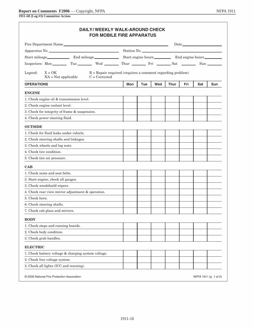
1911-16
Report on Comments F2006 — Copyright, NFPA NFPA 19111911-68 (Log #3) Committee Action
NFPA 1911 (p. 1 of 2)© 2006 National Fire Protection Association
DAILY/ WEEKLY WALK-AROUND CHECK FOR MOBILE FIRE APPARATUS
Fire Department Name Date
Apparatus No. Station No.
Start mileage End mileage Start engine hours End engine hours
Inspectors: Mon Tue Wed Thur Fri Sat Sun
Legend: X = OK R = Repair required (requires a comment regarding problem) NA = Not applicable C = Corrected
ENGINE
1. Check engine oil & transmission level.
2. Check engine coolant level.
3. Check for integrity of frame & suspension.
4. Check power steering fluid.
OUTSIDE
1. Check for fluid leaks under vehicle.
2. Check steering shafts and linkages.
3. Check wheels and lug nuts.
4. Check tire condition.
5. Check tire air pressure.
CAB
1. Check seats and seat belts.
2. Start engine, check all gauges.
3. Check windshield wipers.
4. Check rear view mirror adjustment & operation.
5. Check horn.
6. Check steering shafts.
7. Check cab glass and mirrors.
BODY
1. Check steps and running boards.
2. Check body condition.
3. Check grab handles.
ELECTRIC
1. Check battery voltage & charging system voltage.
2. Check line voltage system.
3. Check all lights (ICC and warning).
OPERATIONS Mon Tue Wed Thur Sat SunFri

1911-17
Report on Comments F2006 — Copyright, NFPA NFPA 19111911-68 (Log #3) Committee Action
NFPA 1911 (p. 2 of 2)© 2006 National Fire Protection Association
BRAKES
1. Check air system for proper air pressure.
2. Check parking brake.
3. Check hydraulic brake fluid level.
PUMP
1. Operate pump, check pump panel engine gauges.
2. Check pump for pressure operation.
3. Check discharge relief or pressure governor operation.
4. Check all pump drain valve.
5. Check all discharge and intake valve operation.
6. Check pump & tank for water leaks.
7. Check all valve bleeder/drain operation.
8. Check primer pump operation.
9. Check system vacuum hold.
10. Check water tank level indicator.
11. Check primer oil level (if applicable).
12. Check transfer valve operation (if equipped).
13. Check booster reel operation (if equipped).
14. Check all pump pressure gauge operation.
15. Check all cooler valves.
16. Check for oil leaks in pump area.
AERIAL
1. Operate aerial hydraulics.
2. Check aerial outrigger operation.
3. Check aerial operation.
4. Check aerial hydraulic fluid level.
5. Visually inspect aerial structure.
Comments
OPERATIONS Mon Tue Wed Thur Sat SunFri

1911-18
Report on Comments F2006 — Copyright, NFPA NFPA 1911____________________________________________________________1911-69 Log #1 Final Action: Accept in Principle(C.3.2)____________________________________________________________Submitter: Gary Handwerk, Hale Products Inc.Comment on Proposal No: 1911-1Recommendation: Add new text as follows: Drive line and pump system mounting bolts, check for tightness and pump transmission oil level and fluid condition.Substantiation: None given.Committee Meeting Action: Accept in Principle Revise the section on Pump and Water Tank Inspection of Figure C.3.2 as follows: Modify the line that reads “Pump transmission” to read “Pump transmission oil level & condition” Add 2 lines at the end of the section to read: ____ Pump mounting integrity ____ Pump driveline U-joints, yokes & flangesCommittee Statement: The committee clarified what to check on the pump transmission, pump mounting, and pump driveline as identified in Chapter 9, Inspection and Maintenance of Water Pumping Systems and Water Tanks.Number Eligible to Vote: 29Ballot Results: Affirmative: 26 Ballot Not Returned: 3 Hillenbrand, T., Pope, G., von Zehle, Jr., W.
____________________________________________________________1911-70 Log #35 Final Action: Accept(Figure C.3.3)____________________________________________________________Submitter: Thomas A. Stalnaker, Goshen Fire CompanyComment on Proposal No: 1911-1Recommendation: Add the following before ROAD and OPERATIONAL TEST:
LINE VOLTAGE
___ Inspect Power Source___ Generator drive engine or power drive train___ Cord reels and Receptacles___ Electrically driven equipment___ Electrical Controls___ Output Voltage _________ Volts___ Output frequency _______ Hz
Comments on line voltage electrical inspection: ________________________________________________________________________________________________________________________________________________________________________________________________________________________________________________________________________________________________________________________________
Substantiation: The line voltage electrical system should be included in the inspection check sheet.Committee Meeting Action: AcceptNumber Eligible to Vote: 29Ballot Results: Affirmative: 26 Ballot Not Returned: 3 Hillenbrand, T., Pope, G., von Zehle, Jr., W.
____________________________________________________________1911-71 Log #49 Final Action: Accept in Principle(Figure C.3.5 (New) )____________________________________________________________Submitter: Lisa Breu, Oshkosh Truck CorporationComment on Proposal No: 1911-1Recommendation: Add new text to read as follows: Battery Tests: Battery Compartment Temperature Battery Charger/Conditioner Test: Rated Output _____ Test Output ___ Pass __ Fail ___Substantiation: Changes to make the test form more closely match the standard text.Committee Meeting Action: Accept in Principle Revise 17.3.2.2.1 (7) to read as follows: Measure and record the temperature in the battery compartment of the battery. Do not revise the battery test line as recommended. Add the lines as recommended for recording the “Battery Charger/Conditioner Test” information.
Committee Statement: It is the temperature of the battery that determines the test criteria. The battery may not even be in the battery compartment when tested. With the change to 17.3.2.2.1(7), the change to the form for battery test is not necessary.Number Eligible to Vote: 29Ballot Results: Affirmative: 26 Ballot Not Returned: 3 Hillenbrand, T., Pope, G., von Zehle, Jr., W.
____________________________________________________________1911-72 Log #36 Final Action: Accept in Principle(Figure C.3.6)____________________________________________________________Submitter: Thomas A. Stalnaker, Goshen Fire CompanyComment on Proposal No: 1911-1Recommendation: Revise Figure C.3.6 as shown on the following pages.Substantiation: Testing checklist should agree with test descriptions both in specific tests and the order of the tests.Committee Meeting Action: Accept in Principle Revise Figure C.3.6 to read as shown on the pages that follow the recommendation.Committee Statement: The committee has added the word “ANNUAL” to the load test to distinguish it from the 5 year FULL LOAD TEST. The revised figure also Includes changes as a result of action on other public comments. Number Eligible to Vote: 29Ballot Results: Affirmative: 26 Ballot Not Returned: 3 Hillenbrand, T., Pope, G., von Zehle, Jr., W.
____________________________________________________________1911-73 Log #34 Final Action: Accept(C.4)____________________________________________________________Submitter: Thomas A. Stalnaker, Goshen Fire CompanyComment on Proposal No: 1911-1Recommendation: Revise text to read as follows: Once the tasks to be performed, the required frequency, and where to have the dork work done have all be been identified, the preventative maintenance program can be documented into a series of schedules, check sheets, record sheets, and other documentation that will insure that the program will be implemented correctly. If this entire program is being developed from scratch, it may be necessary to develop the program and then revise it as experience shows what works and what does not work smoothly and easily.Substantiation: The changes are what were originally intended.Committee Meeting Action: AcceptNumber Eligible to Vote: 29Ballot Results: Affirmative: 26 Ballot Not Returned: 3 Hillenbrand, T., Pope, G., von Zehle, Jr., W.
____________________________________________________________1911-74 Log #69 Final Action: Reject(Annex D)____________________________________________________________Submitter: Michael Chiaramonte, International Association of Fire Chiefs/Eastern DivisionComment on Proposal No: 1911-1Recommendation: Revise as follows: It is recommended that apparatus manufactured prior to 1991 that is less than 25 years old, that has been properly maintained, and that is still in serviceable condition, should be place in reserve status and upgraded to incorporate as many features of the post 1991 fire apparatus as possible (see Section D.3). Apparatus that was not manufactured to the applicable NFPA fire apparatus standards or that is over 25 years old should be replaced.Substantiation: At many conferences it has been stated that vehicles manufactured prior to 1980 are not safe. While they may not have been built to current standards, there was never any documentation of facts presented to support the assumption they are “not safe.” Without supporting documentation this appears to be a personally held belief presented as fact. In fact, a review of fatal fire apparatus accidents between 1999 and 2004 illustrate that newer vehicles have a much higher accident rate than apparatus manufactured prior to 1980. A review of NIOSH recommendations made as a result of investigating these fatal accidents finds there are several trends identified that are not related to the year of manufacture of a vehicle. Putting this into perspective, 24 of 29 (83%) of fire apparatus fatal accidents studied involved vehicle manufactured AFTER 1980. NONE OF THE NIOSH RECOMMENDATIONS INDICATED A NEED TO REMOVE VEHICLES FROM SERVICE IF THEY WERE MANUFACTURED PRIOR TO 1980. The recommendations made by NIOSH deal with issues such as basic vehicle design, maintenance, use, and training as being integral components of vehicle safety and support regular testing and inspection of such vehicles to assure such functionality and operability.

1911-19
Report on Comments F2006 — Copyright, NFPA NFPA 19111911-72 (Log #36) Recommendation
LINE VOLTAGE ELELCTRICAL SYSTEM PERFORMACE TEST
Apparatus number or designation: __________________________________ Year Manufactured: ______________________________________Manufacturer: _________________________________________________________________ Serial Number: __________________________Power Source Type: ___________________________ Manufacturer: _____________________________________________________________Model: __________________________________________Ratings - Volts: ____________ AC/DC: ____________ Phase: ____________ Frequency: ____________ Amps:____________ Watts: ____________
POWER SOURCE LOAD TEST
Test Load Total Wattage: ____________
Test Case Voltage Frequency
No Load at Start
Loaded at Start
Loaded, 0 Minutes
Loaded at End
No Load at End
Minimum Allowed
Maximum Allowed
Pass Fail Pass Fail
OUTLET RECEPTACLE WIRING TESTS
Pass Fail Number of tests: ___________________________________________________________________________________________Identify any problem outlets: ______________________________________________________________________________________________Remarks: ______________________________________________________________________________________________________________
GROUND FAULT CIRCUIT INTERRUPTERS (GFCIs)
Number of GFCIs Tested: ______________ Pass Fail Remarks: __________________________________________________________________________________________________________________________________________________________________________________________________________________________________________________________________________________________________________________________________________________________
OPERATIONAL TESTS OF LINE VOLTAGE EQUIPMENT
Pass Fail Describe any failures or problems: __________________________________________________________________________________________________________________________________________________________________________________________________Remarks: ____________________________________________________________________________________________________________________________________________________________________________________________________________________________________
POWER SOURCE FULL LOAD TESTTest Load Total Wattage: ____________
Test Case Voltage Frequency
0% Load at Start
50% Load at Start
100% Load, 0 Minutes
100% Load, 10 Minutes
100% Load, 20 Minutes
100% Load, 30 Minutes
100% Load, 40 Minutes
50% Load at End
0% Load at End

1911-20
Report on Comments F2006 — Copyright, NFPA NFPA 19111911-72 (Log #36) Recommendation (continued)
Thirty-six fatal vehicle related incidents between 1999 and December 2005 were reviewed. Data from all but one (that occurred in 2005) came from NIOSH reports. Here are the results: - In 28 of 36 incidents (78%) the driver was the fatality - In 21 of 35 incidents (60%) recommendations were made for seat belt use and related standard operating procedures. - In 15 of 35 incidents (43%) recommendations were made for the development and implementation of standard operating procedures related to vehicle operations. - In 13 of 35 incidents (37%) recommendations were made for the implementation of driver training programs. - In 11 of 35 incidents (31%) recommendations were made relative to driver related standard operating procedures being developed and implemented. - In 9 of 35 incidents (26%) vehicle maintenance program recommendations were proposed. - In 5 of 35 incidents (14%) vehicles design-related recommendations were proposed. These critical recommendations are the type of issues requiring action in a design, maintenance, and use standard for fire apparatus, not a retirement of trucks due to age. The case has been made and agreed to that converted vehicles should be removed from service as soon as feasible and these departments with converted vehicles should receive the highest funding priority from the Assistance to Firefighter Grant programs. There is concern developing that this type of unfunded recommendation also establishes new, false standards of care for fire departments that are not based on facts or reality. In addition, for those communities that cannot afford to replace apparatus at the suggested frequency, this could result in a reduction in fire protection for the community. Just because a vehicle is 25 years old, in and of itself, is no reason to mandate its replacement. Many fire departments use high quality, reliable apparatus from the 60s and 70s that provide individuals in those communities with needed protection. The most important component of serviceability remains maintenance, operations procedures, use and training — not age.Reality is that not every vehicle can be replaced immediately even if there was sufficient funding thus making the expectation of apparatus replacement even more unachievable. THE FIRE APPARATUS TECHNICAL COMMITTEE IS ENCOURAGED TO PROMOTE DEPARTMENTS TO ACT SENSIBLY AND REASONABLY IN THE PROCUREMENT, USE, MAINTENANCE, TRAINING AND REPLACEMENT OF VEHICLES.
Committee Meeting Action: RejectCommittee Statement: Technology and safety improvements to fire apparatus in the past 25 years warrant the retirement of older, obsolete fire apparatus. Fire fighters should have the benefit of using apparatus with these improvements for their safety and the reliability of the service they are delivering. Retrofitting older apparatus to incorporate these improvements in most cases is either impossible or impractical. Annex D is a guide to assist fire departments in evaluating their apparatus, it is not a mandatory requirement.Number Eligible to Vote: 29Ballot Results: Affirmative: 22 Negative: 4 Ballot Not Returned: 3 Hillenbrand, T., Pope, G., von Zehle, Jr., W.Explanation of Negative: DORIO, R.: In my opinion the requirement to retire or determine apparatus obsolete after 25 years is arbitrary. I have not seen any documentation that determines apparatus crosses some level of safety threshold after 25 years. Why not 23 or 27 years? FRAZEUR, D.: As written, Annex D is a sunset clause for apparatus. While Annex D is appendix material and therefore a guide, the requirement to replace apparatus that is more than 25 years old is arbitrary, not tied to maintenance issues, refurbishment costs or mandated performance features that were imposed by NFPA 1901 in the year 1991. The committee argues that technology and safety improvements made to apparatus in the past 25 years warrant apparatus retirement. Today, that means apparatus that were built before the year 1981 should be retired. Two years from now, the retirement date changes to 1983. In both cases, the apparatus were built to the same standard. I suggest that other factors including wear, utility and maintenance are more important than physical age in determining when an apparatus should be retired. MCCULLOUGH, II, T.: I believe that there has been insufficient substantiation to demonstrate that emergency service apparatus over 25 years of age (as a class of vehicles) are inherently unsafe. In fact, based on recent reports of fire apparatus accidents in news articles and the fire service press, more accidents occur with newer vehicles, even though there are more old vehicles in service. I concur that apparatus should be taken out of service if they are mechanically unworthy to use. Additionally, suggesting the immediate replacement of apparatus over 25 years of age is unrealistic. Currently, there is no funding stream in place to support this in many communities, it could create an adverse liability situation on many departments and most importantly there isn’t enough manufacturing capacity in the world to build fire engines to replace all of the trucks over 25 years of age currently in service. WHITE, D.: I do not believe that there is any data that shows that fire apparatus over 25 years old is more dangerous than newer units.
Minimum Allowed (-10%) (-3Hz)
Maximum Allowed (+10%) (+3Hz)
Pass Fail Pass Fail
OPERATIONAL TESTS OF POWER SOURCE AND EQUIPMENT
Pass Fail Describe any failures or problems: __________________________________________________________________________________________________________________________________________________________________________________________________________Remarks: ____________________________________________________________________________________________________________________________________________________________________________________________________________________________________________
GROUND FAULT CIRCUIT INTERRUPTERS (GFCIs) Number of GFCIs Tested: ______________ Pass Fail Remarks: ____________________________________________________________________________________________________________________________________________________________________________________________________________________________________________
DIELECTRIC WITHSTAND TESTPass Fail Not Applicable Remarks: _____________________________________________________________________________________________________________________________________________________________________________________________________________________________________________________________________________________________________
Comments on line voltage system performance test: _____________________________________________________________________________________________________________________________________________________________________________________________________________________________________________________________________________________________________________________________________________________________________________________________________________Person conducting the test: _______________________________________________________________________________________Representing: _________________________________________________________________________________________________Signature: _____________________________________________________________________________ Date: _________________AHJ Representative ______________________________________________________________________ Date: _________________

1911-21
Report on Comments F2006 — Copyright, NFPA NFPA 19111911-72 (Log #36) Committee Action
NFPA 1911 (p. 1 of 2)© 2006 National Fire Protection Association
LINE VOLTAGE ELECTRICAL SYSTEM PERFORMANCE TEST
Apparatus number or designation Year manufactured
Manufacturer Serial number
Power source type Manufacturer
Model
Ratings — Volts AC/DC Phase Frequency
Amps Watts
Line voltage system is: � Isolated � Bonded neutral
POWER SOURCE ANNUAL LOAD TEST
Test load total wattage
RECEPTACLE WIRING TESTS
� Pass � Fail Number of tests
Identify any problem receptacles
Remarks
GROUND FAULT CIRCUIT INTERRUPTERS (GFCIs)
� Pass � Fail Number of GFCIs tested
Remarks
No load at start
Loaded at start
Loaded, 10 minutes
Loaded at end
No load at end
Minimum allowed
Maximum allowed
� Pass � Fail� Pass � Fail
Test Case Voltage Frequency

1911-22
Report on Comments F2006 — Copyright, NFPA NFPA 1911
1911-72 (Log #36) Committee Action (continued)
NFPA 1911 (p. 2 of 2)© 2006 National Fire Protection Association
OPERATIONAL TESTS OF LINE VOLTAGE EQUIPMENT
� Pass � Fail Describe any failures or problems
Remarks
POWER SOURCE FULL LOAD TEST
Test load total wattage
DIELECTRIC WITHSTAND TEST
� Pass � Fail � Not applicable Remarks
Comments on line voltage system performance test
Person conducting the test
Representing
Signature Date
AHJ Representative Date
0% load at start
50% load at start
100% load, 0 minutes
100% load, 10 minutes
100% load, 20 minutes
100% load, 30 minutes
100% load, 40 minutes
50% load at end
0% load at end
Minimum allowed
Maximum allowed
(–10%)
(+10%)
(–3Hz)
(+3Hz)
� Pass � Fail� Pass � Fail
Test Case Voltage Frequency

1911-23
Report on Comments F2006 — Copyright, NFPA NFPA 1911____________________________________________________________1911-75 Log #38 Final Action: Reject(D.1)____________________________________________________________Submitter: Gene P. Carlson, VFIS/Glatfelter Insurance GroupComment on Proposal No: 1911-1Recommendation: Revise the third paragraph to read as follows: It is recommended that apparatus manufactured prior to 1991 that is less than 25 years old, that has been properly maintained, and that is still in serviceable condition, should be placed in reserve status and upgraded to incorporate as many features of the post-1991 fire apparatus as possible (see Section D.3). Apparatus that was not manufactured to the applicable NFPA fire apparatus standards or that is over 25 years old should be replaced.Substantiation: At many conferences it has been stated that vehicles manufactured prior to 1980 are not safe. While they may not have been built to current standards, there was never any documentation of facts presented to support he assumption they are “not safe.” Without supporting documentation this appears to be a personally held belief presented as fact. In fact, a review of fatal fire apparatus accidents between 1999 and 2004 illustrate that newer vehicles have a much higher accident rate than apparatus manufactured prior to 1980. A review of NIOSH recommendations made as a result of investigating these fatal accidents finds there are several trends identified that are not related to the year of manufacture of a vehicle. Putting this into perspective, 24 of 29 (83%) of fire apparatus fatal accidents studies involved vehicles manufactured AFTER 1980. NONE OF THE NIOSH RECOMMENDATIONS INDICATED A NEED TO REMOVE VEHICLES FROM SERVICE IF THEY WERE MANUFACTURED PRIOR TO 1980. The recommendations made by NIOSH deal with issues such as basic vehicle design, maintenance, use, and training as being integral components of vehicle safety and support regular testing and inspection of such vehicles to assure such functionality and operability. Thirty-six fatal vehicle related incidents between 1999 and December 2005 were reviewed. Data from all but one (that occurred in 2005) came from NIOSH reports. Here are the results. – In 28 of 36 incidents (78%) the driver was the fatality – In 21 of 35 incidents (60%) recommendations were made for seat belt use and related standard operating procedures – In 15 of 35 incidents (43%) recommendations were made for the development and implementation of standard operating procedures related to vehicle operations – In 13 of 35 incidents (37%) recommendations were made for the implementation of driver training programs – In 11 of 35 incidents (31%) recommendations were made relative to driver related standard operating procedures being developed and implemented – In 9 of 35 incidents (26%) vehicle maintenance program recommendations were proposed – In 5 of 35 incidents (14%) vehicle design-related recommendations were proposed These critical recommendations are the type of issues requiring action in a design, maintenance, and use standard for fire apparatus, not a retirement of trucks due to age. The case has been made and agreed to that converted vehicles should be removed from service as soon as feasible and these departments with converted vehicles should receive the highest funding priority form the Assistance to Firefighter Grant programs.
There is concern developing that this type of unfunded recommendation also establishes new, false standards of care for fire departments that are not based on facts or reality. In addition, for those communities that cannot afford to replace apparatus at the suggested frequency, this could result in a reduction in fire protection for the community. Just because a vehicle is 25 years old, in and of itself, is no reason to mandate its replacement. Many fire departments use high quality, reliable apparatus from the ‘60s and ‘70s that provide individuals in those communities with needed protection. The most important component of serviceability remains maintenance, operational procedures, use and training–not age. Reality is that not every vehicle can be replaced immediately, even if there was sufficient funding thus making the expectation of apparatus replacement even more unachievable. THE FIRE APPARATUS TECHNICAL COMMITTEE IS ENCOURAGED TO PROMOTE DEPARTMENTS TO ACT SENSIBLY AND REASONABLY IN THE PROCUREMENT, USE, MAINTENANCE, TRAINING AND REPLACEMENT OF VEHICLES.Committee Meeting Action: RejectCommittee Statement: Technology and safety improvements to fire apparatus in the past 25 years warrant the retirement of older, obsolete fire apparatus. Fire fighters should have the benefit of using apparatus with these improvements for their safety and the reliability of the service they are delivering. Retrofitting older apparatus to incorporate these improvements in most cases is either impossible or impractical. Annex D is a guide to assist fire departments in evaluating their apparatus, it is not a mandatory requirement.Number Eligible to Vote: 29Ballot Results: Affirmative: 23 Negative:3 Ballot Not Returned: 3 Hillenbrand, T., Pope, G., von Zehle, Jr., W.Explanation of Negative: DORIO, R.: In my opinion the requirement to retire or determine apparatus obsolete after 25 years is arbitrary. I have not seen any documentation that determines apparatus crosses some level of safety threshold after 25 years. Why not 23 or 27 years? FRAZEUR, D.: As written, Annex D is a sunset clause for apparatus. While Annex D is appendix material and therefore a guide, the requirement to replace apparatus that is more than 25 years old is arbitrary, not tied to maintenance issues, refurbishment costs or mandated performance features that were imposed by NFPA 1901 in the year 1991. The committee argues that technology and safety improvements made to apparatus in the past 25 years warrant apparatus retirement. Today, that means apparatus that were built before the year 1981 should be retired. Two years from now, the retirement date changes to 1983. In both cases, the apparatus were built to the same standard. I suggest that other factors including wear, utility and maintenance are more important than physical age in determining when an apparatus should be retired. MCCULLOUGH, II, T.: I believe that there has been insufficient substantiation to demonstrate that emergency service apparatus over 25 years of age (as a class of vehicles) are inherently unsafe. In fact, based on recent reports of fire apparatus accidents in news articles and the fire service press, more accidents occur with newer vehicles, even though there are more old vehicles in service. I concur that apparatus should be taken out of service if they are mechanically unworthy to use. Additionally, suggesting the immediate replacement of apparatus over 25 years of age is unrealistic. Currently, there is no funding stream in place to support this in many communities, it could create an adverse liability situation on many departments and most importantly there isn’t enough manufacturing capacity in the world to build fire engines to replace all of the trucks over 25 years of age currently in service.

FORM FOR FILING NOTICE OF INTENT TO MAKE A MOTION (NITMAM)
AT AN ASSOCIATION TECHNICAL MEETING 2006 FALL REVISION CYCLE
FINAL DATE FOR RECEIPT OF NITMAM: 5:00 pm EST, October 20, 2006
If you have questions about filling out or filing the NITMAM, please contact the Codes and Standards Administration at 617-984-7249
For further information on the Codes- and Standards-Making Process, see the NFPA
website (www.nfpa.org)
FOR OFFICE USE ONLY
Log #: Date Rec'd:
Date________________Name________________________________________________Tel. No.
Company or Affiliation __________________________________________________Email Address
Street Address_________________________________City________________________State______Zip _________________ 1. (a) NFPA Document (include Number and Title)_______________________________________________________________ (b) Proposal or Comment Number____________________ (c) Section/Paragraph _____________________________________
2. Motion to be made. Please check one: (See also 4-6 of the Regulations Governing Committee Projects) (a) Proposal _(1) Accept. (2) Accept an Identifiable Part.* __ (3) Accept as modified by the TC. (4) Accept an Identifiable Part as modified by TC.* (b) Comment (1) Accept. (2) Accept an Identifiable Part.* (3) Accept as modified by the TC. (4) Accept an Identifiable Part as modified by TC.* __ (5) Reject (6) Reject an Identifiable Part.* (c) Return Technical Committee Report for Further Study _____ (1) Return entire Report. (2) Return a portion of a Report in the form of a proposal and related comment(s). _____ (3) Return a portion of a Report in the form of identifiable part(s) of a proposal and related comments (s). (Identify the specific portion of the proposal and the related comments below)* * Clearly identify the Identifiable Part(s) indicated above (use separate sheet if required). ______________________________________________________________________________________________________________________________________________________________________________________________________________________
__________________________
3. I am entitled to make this motion in accordance with 4.6.8 of the Regulations Governing Committee Projects, as follows: (check (a), (b), or (c). (a)____ This motion may be made by the original submitter or their designated representative, and I am the (if you check (a) indicate
one of the following):
___I am the Original submitter, or
___I am the submitter’s designated representative (attach written authorization signed by the original submitter), or
___ I am an Organizational Member delegate permitted to represent the submitter on behalf of the Organization Member in accordance with 4-6.5 (c). (b)____This motion may be made by a Technical Committee Member and I am a Member of the responsible Technical Committee.
(c)____This motion may be made by anyone.
(Form continued on next page)

NITMAM form (continued) 4. Comments or Clarification (optional): This NITMAM will be reviewed by a Motions Committee. In addition to determining whether your Amending Motion is proper, the Committee may take other actions as described in 2.3 of the Technical Meeting Convention Rules as follows:
Restating and Grouping of Motions. Upon request or on its own initiative, and in consultation with the mover(s), the Motions Committee may: (a) restate an Amending Motion to facilitate the making of a proper motion or to clarify the intent of the mover; and (b) group Amending Motions that are dependent on one another into a single Amending Motion. Dependent motions are motions that the mover(s) wish to be considered by the assembly and voted on as single up or down package. In addition to the foregoing, the Motions Committee may take such other actions or make such other recommendations as will facilitate the fair and efficient consideration of amending.
The NFPA Staff may contact you to clarify your motion or to consult on the permitted actions in 2.3. If you have any comments, suggestions, or requests of the Motions Committee as it reviews your NITMAM and considers actions permitted in 2.3, please provide them below. (Use additional sheet if necessary): __________________________________________________________________________________________________________________________
__________________________________________________________________________________________________________________________
_________________________________________________________________________________________________________________________
__________________________________________________________________________________________________________________________
__________________________________________________________________________________________________________________________
__________________________________________________________________________________________________________________________
__________________________________________________________________________________________________________________________
__________________________________________________________________________________________________________________________
__________________________________________________________________________________________________________________________
__________________________________________________________________________________________________________________________
__________________________________________________________________________________________________________________________
__________________________________________________________________________________________________________________________
Name (please print):_____________________________________________________________________
Signature (Required)_____________________________________________________________________ (Note: This NITMAM will be reviewed, and if proper, your Amending Motion will be certified in accordance with the Technical Meeting Convention Rules and posted on the NFPA website by November 17, 2006. Documents that have Certified Amending Motions will be considered at the June 2007 Annual Meeting Technical Committee Report. In order to have your Certified Amending Motion considered at that meeting, you must appear, sign in, and make the motion as prescribed in the Convention Rules).
PLEASE USE A SEPARATE NITMAM FORM FOR EACH AMENDING MOTION YOU WISH TO MAKE,
Mail to: Secretary, Standards Council, National Fire Protection Association, 1 Batterymarch Park, Quincy, MA 02169-7471 NFPA Fax: (617) 770-3500

Sequence of Events Leading to Issuance of an NFPA Committee Document
Step 1 Call for Proposals
▼ Proposed new Document or new edition of an existing Document is entered into one of two yearly revision cycles, and a Call for Proposals is published.
Step 2 Report on Proposals (ROP)
▼ Committee meets to act on Proposals, to develop its own Proposals, and to prepare its Report.
▼ Committee votes by written ballot on Proposals. If two-thirds approve, Report goes forward. Lacking two-thirds approval, Report returns to Committee.
▼ Report on Proposals (ROP) is published for public review and comment.
Step 3 Report on Comments (ROC)
▼ Committee meets to act on Public Comments to develop its own Comments, and to prepare its report.
▼ Committee votes by written ballot on Comments. If two-thirds approve, Reports goes forward. Lacking two-thirds approval, Report returns to Committee.
▼ Report on Comments (ROC) is published for public review.
Step 4 Technical Report Session
▼ “Notices of intent to make a motion” are filed, are reviewed, and valid motions are certified for presentation at the Technical Report Session. (“Consent Documents” that have no certified motions bypass the Technical Report Session and proceed to the Standards Council for issuance.)
▼ NFPA membership meets each June at the Annual Meeting Technical Report Session and acts on Technical Committee Reports (ROP and ROC) for Documents with “certified amending motions.”
▼ Committee(s) vote on any amendments to Report approved at NFPA Annual Membership Meeting.
Step 5 Standards Council Issuance
▼ Notification of intent to file an appeal to the Standards Council on Association action must be filed within 20 days of the NFPA Annual Membership Meeting.
▼ Standards Council decides, based on all evidence, whether or not to issue Document or to take other action, including hearing any appeals.
I

The Technical Report Session of the NFPA Annual Meeting
The process of public input and review does not end with the publication of the ROP and ROC. Following the completion of the Proposal and Comment periods, there is yet a further opportunity for debate and discussion through the Technical Report Sessions that take place at the NFPA Annual Meeting.
The Technical Report Session provides an opportunity for the final Technical Committee Report (i.e., the ROP and ROC) on each proposed new or revised code or standard to be presented to the NFPA membership for the debate and consideration of motions to amend the Report. The specific rules for the types of motions that can be made and who can make them are set forth in NFPA’s rules which should always be consulted by those wishing to bring an issue before the membership at a Technical Report Session. The following presents some of the main features of how a Report is handled.
What Amending Motions are Allowed. The Technical Committee Reports contain many Proposals and Comments that the Technical Committee has rejected or revised in whole or in part. Actions of the Technical Committee published in the ROP may also eventually be rejected or revised by the Technical Committee during the development of its ROC. The motions allowed by NFPA rules provide the opportunity to propose amendments to the text of a proposed code or standard based on these published Proposals, Comments and Committee actions. Thus, the list of allowable motions include motions to accept Proposals and Comments in whole or in part as submitted or as modified by a Technical Committee action. Motions are also available to reject an accepted Comment in whole or part. In addition, Motions can be made to return an entire Technical Committee Report or a portion of the Report to the Technical Committee for further study.
The NFPA Annual Meeting, also known as the World SafetyConference and Exposition®, takes place in June of each year. A second Fall membership meeting was discontinued in 2004, so the NFPA Technical Report Session now runs once each yearat the Annual Meeting in June.
Who Can Make Amending Motions. Those authorized to make these motions is also regulated by NFPA rules. In many cases, the maker of the motion is limited by NFPA rules to the original submitter of the Proposal or Comment or his or her duly authorized representative. In other cases, such as a Motion to Reject an accepted Comment, or to Return a Technical Committee Report or a portion of a Technical Committee Report for Further Study, anyone can make these motions. For a complete explanation, NFPA rules should be consulted.
The filing of a Notice of Intent to Make a Motion. Before making an allowable motion at a Technical Report Session, the intended maker of the motion must file, in advance of the session, and within the published deadline, a Notice of Intent to Make a Motion. A Motions Committee appointed by the Standards Council then reviews all notices and certifies all amending motions that are proper. The Motions Committee can also, in consultation with the makers of the motions, clarify the intent of the motions and, in certain circumstances, combine motions that are dependent on each other together so that they can be made in one single motion. A Motions Committee report is then made available in advance of the meeting listing all certified motions. Only these Certified Amending Motions, together with certain allowable Follow-Up Motions (that is, motions that have become necessary as a result of previous successful amending motions) will be allowed at the Technical Report Session.
Consent Documents. Often there are codes and standards up for consideration by the membership that will be non-controversial and no proper Notices of Intent to Make a Motion will be filed. These “Consent Documents” will bypass the Technical Report Session and head straight to the Standards Council for issuance. The remaining Documents are then forwarded to the Technical Report Session for consideration of the NFPA membership.
Important Note: The filing of a Notice of Intent to Make a Motion is a new requirement that takes effect beginning with those Documents scheduled for the Fall 2005 revision cycle that reports to the June 2006 Annual Meeting Technical Report Session. The filing of a Notice of Intent to Make a Motion will not, therefore, be required in order to make a motion at the June 2005 Annual Meeting Technical Report Session. For updates on the transition to the new Notice requirement and related new rules effective for the Fall 2005 revision cycle and the June 2006 Annual Meeting, check the NFPA website.
II

Action on Motions at the Technical Report Session. In order to actually make a Certified Amending Motion at the Technical Report Session, the maker of the motion must sign in at least an hour before the session begins. In this way a final list of motions can be set in advance of the session. At the session, each proposed Document up for consideration is presented by a motion to adopt the Technical Committee Report on the Document. Following each such motion, the presiding officer in charge of the session opens the floor to motions on the Document from the final list of Certified Amending Motions followed by any permissible Follow-Up Motions. Debate and voting on each motion proceeds in accordance with NFPA rules. NFPA membership is not required in order to make or speak to a motion, but voting is limited to NFPA members who have joined at least 180 days prior to the session and have registered for the meeting. At the close of debate on each motion, voting takes place, and the motion requires a majority vote to carry. In order to amend a Technical Committee Report, successful amending motions must be confirmed by the responsible Technical Committee, which conducts a written ballot on all successful amending motions following the meeting and prior to the Document being forwarded to the Standards Council for issuance.
Standards Council Issuance
One of the primary responsibilities of the NFPA Standards Council, as the overseer of the NFPA codes and standards development process, is to act as the official issuer of all NFPA codes and standards. When it convenes to issue NFPA documents it also hears any appeals related to the Document. Appeals are an important part of assuring that all NFPA rules have been followed and that due process and fairness have been upheld throughout the codes and standards development process. The Council considers appeals both in writing and through the conduct of hearings at which all interested parties can participate. It decides appeals based on the entire record of the process as well as all submissions on the appeal. After deciding all appeals related to a Document before it, the Council, if appropriate, proceeds to issue the Document as an official NFPA code or standard. Subject only to limited review by the NFPA Board of Directors, the Decision of the Standards Council is final, and the new NFPA code or standard becomes effective twenty days after Standards Council issuance. The illustration on page 9 provides an overview of the entire process, which takes approximately two full years to complete.
III


![Report on Proposals F2006 — Copyright, NFPA NFPA 1402John M. Best, John Jay College of Criminal Justice, MD [U] Donald T. Brady, Kidde Fire Trainers, Incorporated, NJ [M] Gene P.](https://static.fdocuments.in/doc/165x107/5e7c326c47612c5c7a2726e2/report-on-proposals-f2006-a-copyright-nfpa-nfpa-1402-john-m-best-john-jay-college.jpg)

![Report on Proposals F2006 — Copyright, NFPA NFPA 1851 · Frank P. Taylor, Lion Apparel, Incorporated, VA [M] (Alt. to Nicholas J. Curtis) Nonvoting Donna P. Brehm, Virginia Beach](https://static.fdocuments.in/doc/165x107/5fa9e8739530363ed80d406e/report-on-proposals-f2006-a-copyright-nfpa-nfpa-1851-frank-p-taylor-lion-apparel.jpg)