Challenges Associated With Separations in Production of Hydrogen Using Thermochemical Cycles

U.S. Department of Energy Energy Efficiency and Renewable EnergyBringing you a prosperous future where energy is clean, abundant, reliable and affordable
Report of theDOE Workshop onHydrogen Separationsand Purification September 8-9, 2004 Arlington, VA
U.S. Department of EnergyOffice of Hydrogen, Fuel Cells& Infrastructure Technologies

CONTENTS
INTRODUCTION ...............................................................................................1Background ................................................................................................................. 1Current Hydrogen Separation Technology .................................................................. 2Hydrogen Membrane Separation Technologies .......................................................... 3
HYDROGEN MEMBRANE SEPARATION PERFORMANCE TARGETS.........................6
KEY TECHNOLOGY BARRIERS........................................................................ 10Membrane Materials…………..………………………………………………………… 10Membrane Stability/Durability...……………………………………………………...... 10Fundamental Understanding…………………………………………………………… 10Membrane Fabrication and Defect Management……………………………………. 10Membrane Supports…………………………………………………………………….. 10Membrane Module Construction and Testing………………………………………… 10System Integration/Process Intensification…………………………………………… 10
HIGH-PRIORITY RESEARCH & DEVELOPMENT NEEDS .....................................11Develop Advanced Membrane Materials and Rapid Testing Methods……………. 11Develop Cost-Effective Membrane Fabrication Methods…………………………… 11Develop High-Performance, Low-Cost Support Materials………………………….. 11Develop Optimal Module Designs and Construction and Testing Methods………. 12Investigate Opportunities For and Benefits of System Integration/Process Intensification…………………………………………………………………………….. 12Pursue a Multi-Disciplinary, Stage-Gate R&D Strategy………………………………12
APPENDICES A. Workshop Agenda................................................................................................A-1 B. List of Workshop Participants...............................................................................B-1 C. Breakout Group Members ................................................................................... C-1 D. Detailed Breakout Group Results........................................................................ D-1
DOE Workshop on Hydrogen Separation and Purification Technologies i

INTRODUCTIONINTRODUCTION
In September 2004, the U.S. Department of Energy held a Workshop on Hydrogen Separations and Purification Technologies to explore technical approaches for lowering the cost of high-purity hydrogen. Specifically, the workshop examined the potential to significantly improve the economics of hydrogen production in the near and mid term using either of two production pathways:
♦ Distributed (less than 1,500 kg H2/day) reforming of natural gas and renewable liquid fuels (e.g., ethanol, methanol)
♦ Semi-centralized or centralized gasification/pyrolysis of biomass or coal.
The Proceedings of the Hydrogen Separations and Purification Workshop are available on-line at http://www.eere.energy.gov/hydrogena ndfuelcells/wkshp_separations.html.
Here you can download the presentations from the meeting, including remarks from the Department of Energy and the National Institute of Standards and Technology, as well as the presentations from four membrane technology experts.
At the workshop, representatives from industry and the research community provided input on various separation technology options and defined the research and development (R&D) required to help achieve DOE’s 2010-2015 cost goals for delivered hydrogen.1 The workshop was sponsored by the DOE Office of Hydrogen, Fuel Cells and Infrastructure Technologies (OHFCIT) in cooperation with the Office of Fossil Energy (FE), which are working together to coordinate R&D activities in this area. This report presents the results of the workshop.
Background The President’s Hydrogen Fuel Initiative provides funding to accelerate R&D of hydrogen fuel and infrastructure technology. The goal is to enable industry to make commercialization decisions by 2015, so that hydrogen fuel cell vehicles can be available for purchase in showrooms by 2020. Success will require hydrogen production and distribution at a price that is competitive with gasoline, as well as hydrogen fuel cell vehicles that are competitive with gasoline and electric-hybrid vehicles.
Hydrogen production costs are currently too high. The estimated cost for hydrogen generated through the on-site reforming of natural gas at refueling stations using currently available technology is projected to be $3.00-$5.00/kg.2 The long term DOE goal is to develop technologies to be able to produce and deliver hydrogen utilizing a variety of domestic resources in a manner that results in near-zero net greenhouse gas and other emissions. The net fuel cost of operating the hydrogen powered vehicle ($/mile) must be equivalent to alternative vehicles for the hydrogen vehicles to be competitive in the marketplace. The DOE is researching a broad range of hydrogen production and delivery options including on-site reforming of ethanol or methanol; centralized coal gasification (with carbon sequestration) and biomass gasification with
1 $1.50/kg for distributed production from natural gas (untaxed, at the pump by 2010), based on a natural gas price of $4.50/MM Btu; less than $2.60/kg for central production from biomass gasification/pyrolysis (untaxed, at the pump by 2015); and $1.80/kg for central production from coal gasification/pyrolysis (untaxed, at the pump by 2015). The $1.50/kg for distributed natural gas target is currently under review by the FreedomCAR and Fuels Partnership.2 U.S. Department of Energy, Hydrogen, Fuel Cells and Infrastructure Technologies Program Multi-Year Research, Development and Demonstration Plan, December 2004.
DOE Workshop on Hydrogen Separation and Purification Technologies 1

hydrogen delivery via truck or pipeline, electrolysis, photolytic hydrogen production, and high temperature thermochemical cycle production using solar or nuclear energy. Major technology advances are needed to lower equipment and operating costs for these technologies to meet the low cost required to be competitive.
For the distributed natural gas reforming pathway, a sensitivity analysis identified three critical components of hydrogen cost. Based on current cost estimates, major progress will be required in all three of these component areas to meet the 2010 cost goal of $1.50/kg. As shown in Table 1, capital costs will need to come down by 53%, operating and maintenance (O&M) costs will have to decrease by 39%, and system efficiency will need to improve by 10%. Similar challenges face the technology development pathways for distributed liquid fuel reforming and centralized coal or biomass gasification. Advanced hydrogen separation technology is a promising option for simultaneously lowering capital equipment and operating costs and improving overall system efficiency.
Table 1. Key Cost Factors for Distributed Steam Methane Reforming of Natural Gas (1,500kgH2/day)
Cost Factor 2005 Proposed 2010 Target for $1.50/kg H2
% Change from 2005
Capital Costs ($MM) $3.2 $1.4 -56%
Non-Feedstock O&M Costs ($/kg)
$0.80 $0.48 -40%
Energy Efficiency (%) 65 75 +16%
Current Hydrogen Separation Technology The hydrogen-rich gas mixture produced via reforming or gasification contains 40-70% hydrogen and a variety of contaminants including carbon monoxide, carbon dioxide, nitrogen, methane, water, sulfur, and possibly tar and ash. The necessary purity of hydrogen in a polymer electrolyte membrane (PEM) fuel cell is not clearly elucidated by the percentage; while some chemicals do not affect membrane performance even in large amounts, others can cause detrimental effects in small quantities. Common safe chemicals (such as nitrogen) are considered diluting agents and must be removed simply to reduce compression and storage volumes. Dangerous agents (such as carbon monoxide, sulfur, and ammonia) are considered impurities and must be almost entirely removed. PEMs are poisoned by CO at more than 10 parts per million and by sulfur at the parts-per-billion level. Based on current available PEM fuel cell information, the tentative contaminant targets are: <10ppb sulfur, <1 ppm carbon monoxide, <100 ppm carbon dioxide, < 1 ppm ammonia, < 100 ppm non-methane hydrocarbons on a C-1 basis, oxygen, nitrogen and argon can not exceed 2% in total, particulate levels must meet ISO standard 14787. Future information on contaminant limits for on-board storage may add additional constraints. By contrast, solid-oxide fuel cells (SOFCs) for stationary applications can accept a less pure hydrogen feed, since they are not poisoned by carbon monoxide (CO) and can tolerate some sulfur.
Hydrogen separation technology separates hydrogen molecules from a mixed gas stream (such as a synthesis gas from natural gas, coal, or biomass) and produces a purified hydrogen gas stream.
DOE Workshop on Hydrogen Separation and Purification Technologies 2

Current technology for large-scale, industrial hydrogen production typically employs a two-step system for purifying hydrogen from the feed gas:
1) One or two water-gas-shift (WGS) reactor(s) generate additional hydrogen from the CO in the gas mixture
2) A pressure-swing adsorption (PSA) unit removes impurities such as CO, CO2, CH4, H2O, H2S, etc.
Depending on the hydrogen purity required, polishing filters may also be employed to remove specific trace impurities. Each of these steps adds capital and operating costs to the system and affects overall system efficiency. PSA systems increase the capital cost of the overall reforming system by up to 10% and represent a parasitic power loss.3 Integrating or replacing the WGS reactor(s) and/or PSA unit with advanced hydrogen integrated reaction and separation membrane modules may significantly reduce hydrogen production costs by reducing capital costs, lowering O&M costs, and improving system efficiency.
Hydrogen separation membrane technologies may offer a number of advantages over current hydrogen separation technology:
♦ Lower capital costs
♦ Smaller physical space requirements
♦ Fewer moving parts
♦ Higher hydrogen recovery rates
♦ Ability to produce hydrogen at a steady state (a single-unit PSA system produces hydrogen in batches)
♦ Ability to produce high-purity hydrogen without polishing filters
♦ Potential for integration with hydrogen generation technologies so that hydrogen shift and purification or possibly reforming, shift and purification are carried out in a single, simplified, compact “membrane reactor” system
♦ Improved thermal efficiency by eliminating the need to cool and reheat gases for gas clean-up and shift reactions
Hydrogen Membrane Separation Technologies Currently, no membrane separation technology can simultaneously meet all of the performance criteria for a hydrogen fuel production system, including high hydrogen flux at low pressure drops; tolerance to contaminants; low cost; operation at system temperatures of 250-600oC; durability; and robust performance under harsh operating environments. The variety of membrane types being investigated can be grouped into three categories, based on the hydrogen transport mechanism used across the membrane: molecular, atomic, and ionic (i.e., proton transport).
3 “Analysis of Hydrogen Purification Technologies: Phase One Summary,” Review presentation to DOE, April 10, 2002, TIAX, LLC, Cambridge, MA.
DOE Workshop on Hydrogen Separation and Purification Technologies 3

Molecular Transport Membranes
Molecular transport (microporous) membranes are essentially micro-filters. The pores of the membrane are sized to enable the very small hydrogen molecule (at 2.89Å) to move through the membrane while larger gas molecules are left behind. Selectivity is based not only on molecular size but also on how the molecule moves through the medium (mean free path) and on the viscosity of the gas stream. Permeation rate is affected by the pore size, thickness, tortuosity, and total porosity (pore volume) of the membrane. For a membrane to be defined as microporous, its pores must be less than 20Å in diameter; however, hydrogen separation generally requires pores smaller than 10Å. The rate of hydrogen permeation (flux) is directly proportional to the pressure, and is positively affected by increasing temperature. These membranes have the potential to produce hydrogen with a purity of up to 99% in a single pass, and can be made from a number of materials, including ceramics, carbon, and metals. Purity levels of greater than 99% (e.g., 99.99%) can only be achieved by using multiple microporous, membrane stages, or perhaps by developing a hybrid membrane that combines a microporous and a dense metallic layer. Commonly used materials are zeolites, SiC, metal composites, silica, and alumina. Ceramics are particularly attractive in this application, because they provide significant thermal and chemical stability in harsh operating environments.4
Atomic Transport
Atomic transport membranes (also referred to as dense metallic membranes) transport hydrogen atoms that have dissolved into a dense metal matrix. These membranes are comprised of a thin, dense metallic layer (usually palladium or palladium alloys) supported on a porous layer. Upon coming into contact with the metal film, molecular hydrogen dissociates into atoms that then pass through the film and recombine into hydrogen molecules. The metal layer is typically formed from metal composites, thin palladium, or a palladium-alloy metal that is supported on an inexpensive, mechanically strong support. The hydrogen diffuses to the metal surface, where dissociative chemisorption occurs, followed by absorption into the bulk metal, diffusion through the metal lattice, recombination into molecular hydrogen at the opposite surface, and finally diffusion away from the metal membrane. These micro-thin metallic films can be poisoned by gaseous impurities like sulfur compounds and carbon monoxide, and at high temperatures they can undergo phase changes that significantly reduce the hydrogen flux. Alloying with other metals like copper and silver reduces this phase change propensity. The flux for these membranes is proportional to the difference of the square roots of the partial pressure of the hydrogen across the membrane. Because only hydrogen is transported through the membrane, it is possible to produce a 100%-pure hydrogen permeate.
Proton Transport Membranes
Proton transport membranes have the ability to conduct protons (or cations) and electrons independently, such that hydrogen is dissociated on one side and re-constituted on the other. There are two types of proton transport membranes: those that consist of one material phase and those that consist of two.
1) Purely Mixed Conducting Membranes: This type of dense membrane is made of one material phase—ceramic (usually a perovskites/brownmillerite/pyrochlores oxide
4 U.S. Department of Energy, Office of Fossil Energy, Hydrogen from Coal Program Research, Development, and Demonstration Plan: 2004-2015, June 2004 (External Draft for Review).
DOE Workshop on Hydrogen Separation and Purification Technologies 4

composition)—that is capable of conducting both protons and electrons to provide adequate fluxes at high temperatures (>800°C). This type of membrane has demonstrated low electron conductivities, but doping can mitigate this problem. However, the hydrogen flux in purely mixed, conducting ceramic membranes is still rather low for practical hydrogen separation applications. By changing the materials that make up the membrane, oxygen can be selectively transported instead of hydrogen; this approach has been highly successful in oxygen transfer systems for air separation.
2) Cermet Membranes: One approach to increase the hydrogen flux is to fabricate cermet membranes. This type of membrane consists of both a composite, dense-phase ceramic and a metallic phase, hence the term “cermet.” There are two general approaches to cermet membrane configuration. In the first, an electron-conducting metallic phase is combined with a dense conducting ceramic matrix phase. The purpose of the metal in this type (often nickel) is to increase the electron conduction and thereby increase the overall hydrogen flux. In the second approach, a hydrogen-permeable metallic phase is combined with the dense-phase ceramic. This metallic phase (like Pd or Pd/Ag) functions in the same way as the atomic transport membrane mentioned previously.
In both of these types of proton transport membranes, the hydrogen flux depends on both the electron and proton conductivities of the membrane. This is because every two protons transferred must react with two electrons to produce molecular hydrogen. Also, the flux is proportional to the natural log of the hydrogen partial pressure gradient across the membrane, and generally increases with operating temperature. In general, proton transport membranes have a lower hydrogen flux and a more limited operating range than the other two membrane options.
DOE Workshop on Hydrogen Separation and Purification Technologies 5

HYDROGEN MEMBRANE SEPARATIONPERFORMANCE TARGETSHYDROGEN MEMBRANE SEPARATION PERFORMANCE TARGETS
Tables 2, 3, and 4 (below) show the performance targets that have been established to date for hydrogen membrane separation technologies.5 These targets will also be published in the updated version of the DOE Office of Hydrogen, Fuel Cells and Infrastructure Technologies’ Multi-Year Research and Development Plan (January 2005). These targets will be revised as more information is gathered on the capabilities and performance of membrane systems, and on the specific conditions and configurations in which they are expected to operate. Workshop participants offered a variety of suggestions for modifying the performance targets. Key suggestions are summarized in Table 5 and will be considered as the targets are revised.
Table 2. Technical Targets: Dense Metallic Membranes for Hydrogen Separation and Purification
Performance Criteriaa Units
Calendar Year
2003 Statusb 2005 Target 2010 Target 2015 Target
Fluxc scfh/ft2 60 100 200 300
Membrane Material and All Module Costsd
$/ft2 of membrane $2,000 $1,500 $1,000 <$500
Durability Yearse <1f 1 3 >5
∆P Operating Capabilityg psi 100 200 400 400-1,000
Hydrogen Recovery % of total gas 60 >70 >80 >90
Hydrogen Purityh % of total (dry) gas >99.9 >99.9 >99.95 99.99%
a The membranes must be tolerant to impurities. This will be application specific. Common impurities include, sulfur and carbon monoxide.
b Based on membrane shift reactor with syngas. c Flux at 20 psi hydrogen partial pressure differential with a minimum permeate side pressure of 15 psi,
preferably >50psi, and 400o C d The membrane support structure is approximately three times membrane material costs. e Intervals between membrane replacement.f Hydrogen membranes have not been demonstrated to date, only laboratory tested. g Delta P operating capability is application dependent. There are many apllications that may only require 400 psi
or less. For coal gasification 1000 psi is the target.h Based on current available PEM fuel cell information, the tentative contaminant targets are: <10 ppb sulfur; <1
ppm carbon monoxide; <100 ppm carbon dioxide; < 1 ppm ammonia; < 100 ppm non-methane hydrocarbons on a C-1 basis; oxygen, nitrogen and argon cannot exceed 2% in total; particulate levels must meet ISO standard 14787. Future information on contaminant limits for on-board storage may add additional constraints.
Notes: Revised targets take into consideration input received at the September 2004 Hydrogen Separations Workshop. These targets are undergoing detailed engineering analysis. Membrane systems should be demonstrated within a temperature range of 250-1,000oC. Also, parasitic power requirements (power used to recompress the hydrogen downstream of the membrane due to potential pressure drops across the membrane) should be minimized.
5 Also see the Hydrogen from Coal Program Research, Development, and Demonstration Plan: 2004-2015. U.S. Department of Energy, Office of Fossil Energy, 2004, which presents targets for microporous membranes.
DOE Workshop on Hydrogen Separation and Purification Technologies 6
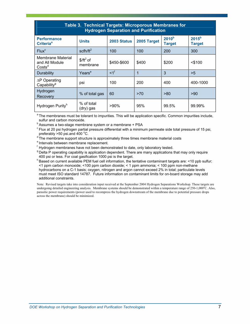
Table 3. Technical Targets: Microporous Membranes for Hydrogen Separation and Purification
Performance Criteriaa Units 2003 Status 2005 Target 2010b
Target 2015b
Target
Fluxc scfh/ft2 100 100 200 300 Membrane Material and All Module Costsd
$/ft2 of membrane $450-$600 $400 $200 <$100
Durability Yearse <1f 1 3 >5
∆P Operating Capabilityg psi 100 200 400 400-1000
Hydrogen Recovery
% of total gas 60 >70 >80 >90
Hydrogen Purityh % of total (dry) gas >90% 95% 99.5% 99.99%
a The membranes must be tolerant to impurities. This will be application specific. Common impurities include, sulfur and carbon monoxide.
b Assumes a two-stage membrane system or a membrane + PSA c Flux at 20 psi hydrogen partial pressure differential with a minimum permeate side total pressure of 15 psi,
preferably >50 psi.and 400 oC. d The membrane support structure is approximately three times membrane material costs e Intervals between membrane replacement.f Hydrogen membranes have not been demonstrated to date, only laboratory tested. g Delta P operating capability is application dependent. There are many applications that may only require
400 psi or less. For coal gasification 1000 psi is the target.h Based on current available PEM fuel cell information, the tentative contaminant targets are: <10 ppb sulfur;
<1 ppm carbon monoxide; <100 ppm carbon dioxide; < 1 ppm ammonia; < 100 ppm non-methane hydrocarbons on a C-1 basis; oxygen, nitrogen and argon cannot exceed 2% in total; particulate levels must meet ISO standard 14787. Future information on contaminant limits for on-board storage may add additional constraints.
Note: Revised targets take into consideration input received at the September 2004 Hydrogen Separations Workshop. These targets are undergoing detailed engineering analysis. Membrane systems should be demonstrated within a temperature range of 250-1,000oC. Also, parasitic power requirements (power used to recompress the hydrogen downstream of the membrane due to potential pressure drops across the membrane) should be minimized.
DOE Workshop on Hydrogen Separation and Purification Technologies 7

Table 4. Technical Targets: Proton Transport Membranes for Hydrogen Separation and Purification
Performance Criteriaa
Units 2003 Status
2005 Target
2010 Target
2015 Target
Fluxb scfh/ft2 60 100 150 200c
Costd $/ft2 of membrane
>1,000 $500 $200 <$100
Durability Yearse <1f 1 3 >5
∆P Operating Capabilityg
psi 200 300 400 400-1000
Hydrogen Recovery
% of total gas Data Not Available
80 90 100
Hydrogen Purityh % of total (dry) gas
>90% 95% 99.5% 99.99%
a The membranes must be tolerant to impurities. This will be application specific. Common impurities include, sulfur and carbon monoxide.
b Flux at 20 psi hydrogen partial pressure differential with a minimum permeate side total pressure of 15 psi, preferably >50 psi. and 400oC.
c Flux upper limit for Proton Transport Membranes.d Cost of the membrane area available for H2 extraction including material and module support structure e Intervals between membrane replacement.f Hydrogen membranes have not been demonstrated to date, only laboratory tested. g Delta P operating capability is application dependent. There are many apllications that may only require
400 psi or less. For coal gasification 1000 psi is the target.h Based on current available PEM fuel cell information, the tentative contaminant targets are: <10 ppb sulfur;
<1 ppm carbon monoxide; <100 ppm carbon dioxide; < 1 ppm ammonia; < 100 ppm non-methane hydrocarbons on a C-1 basis; oxygen, nitrogen and argon cannot exceed 2% in total; particulate levels must meet ISO standard 14787. Future information on contaminant limits for on-board storage may add additional constraints.
Note: Revised targets take into consideration input received at the September 2004 Hydrogen Separations Workshop. These targets are undergoing detailed engineering analysis. Membrane systems should be demonstrated within a temperature range of 250-1,000oC. Also, parasitic power requirements (power used to recompress the hydrogen downstream of the membrane due to potential pressure drops across the membrane) should be minimized.
DOE Workshop on Hydrogen Separation and Purification Technologies 8

Table 5. Suggestions for Modifying Performance Targets for Hydrogen Separation Membranes
Flux • Change to flow rate (kg H2/day), which will vary by application.
Cost • Define whether the cost is for the membrane only, the membrane plus supports, or the entire membrane module (membrane, module, and housing). Define targets for both capital and operating & maintenance costs over a specified lifetime.
• Cost targets should be $/kg H2
Operating Temperature
• Define specific, more narrow temperature ranges expected for different applications so that membranes can be tailored and tested for those conditions.
• Specify feed and permeate temperatures by application.
Hydrogen Purity
• Define the hydrogen purity and contaminant levels that are required for specific end-use applications
Overall • Establish an overarching goal of $/scf (or kg) of hydrogen that all membrane separation technologies will need to meet.
DOE Workshop on Hydrogen Separation and Purification Technologies 9

KEY TECHNOLOGY BARRIERSKEY TECHNOLOGY BARRIERS
There are many technical barriers that currently limit the ability to meet the technical and economic performance targets for hydrogen membrane separation systems, as summarized below. The detailed results of the workshop’s breakout discussion sessions are presented in Appendix D.
Membrane Materials ♦ Inadequate, slow screening and testing methods for identification of new materials
♦ Lack of novel materials (alloys, ceramics, composites, hybrids) that provide optimum diffusivity, flux, and contaminant resistance
Membrane Stability/Durability
♦ Poor resistance to thermal cycling ♦ Inverse relationship of durability and flux
Fundamental Understanding
♦ Inadequate or unknown resistance to contaminants in the syngas ♦ Lack of standardized, accelerated aging tests
♦ Poor understanding of mass transport diffusion through membranes
Membrane Fabrication and Defect Management
♦ Poor understanding of microstructural evolution during membrane operation and effect on permeance and selectivity
♦ Lack of optimal methodologies for large-scale production/fabrication of defect-free, thin film membranes
♦ Lack of in-situ membrane repair or regeneration (defect healing) methodologies
♦ Lack of companies who have experience fabricating membranes
Membrane Supports ♦ Lack of light-weight, low cost supports that can achieve target operating performance
Membrane Module Construction and Testing
♦ Inadequate module designs ♦ Lack of cost-effective large scale manufacturing methodologies
that incorporate modular design, compact assemble, and life time cost minimization
♦ Lack of sealing and joining technology ♦ Lack of benchmarks for module testing (standardized testing
protocols, detailed gas feedstock specifications, accelerated aging tests, etc.)
System Integration/Process Intensification
♦ Incomplete understanding of how a water-gas-shift reactor might be integrated with a hydrogen membrane separation system
♦ Lack of comparative studies/system analysis of alternative system configurations
♦ Poor understanding of mass transfer limitations in integrated systems
DOE Workshop on Hydrogen Separation and Purification Technologies 10

HIGH-PRIORITY RESEARCH& DEVELOPMENT NEEDSHIGH-PRIORITY RESEARCH & DEVELOPMENT NEEDS
A number of high-priority R&D needs have been identified for hydrogen separation technologies, as summarized below. Recurring themes among the top-priority R&D needs are:
1) Standard, application-specific test methods for membrane and modules are needed to effectively focus R&D and provide a clear means for making go/no-go decisions and for comparing the performance of alternatives
2) Investigations are needed that pursue an integrated approach to the development of the membrane, support, and module design/construction
3) Predictive models are needed for assessing the technical and economic performance of alternative membrane/module designs and systems configurations
The detailed results of the workshop’s breakout discussion sessions on R&D needs are presented in Appendix D.
Develop Advanced Membrane Materials and Rapid Testing Methods
♦ Develop and make publicly available rapid-screening tools to discover novel materials (e.g., novel metal alloys, new families of ceramics, nano-composites, novel hybrids) - establish key performance metrics and standard testing
protocols - link choice of material to membrane thickness requirements
♦ Conduct root cause analysis of membrane degradation and failure mechanisms in order to understand the effects of contaminants, thermal and pressure cycling, etc., and use this knowledge to develop more robust, durable membranes
♦ Perform systematic study of the effects of feedstock gas constituents on membrane stability, flux, and permeate purity
♦ Conduct fundamental research to improve understanding of mass transport mechanisms and kinetic/thermodynamic impacts of feedstock constituents on the membrane
♦ Develop models to predict performance and failure modes of membrane materials under varying operating conditions
♦ Establish membrane test-bed facilities accessible to industry supplied with standard feed gas samples
Develop Cost-Effective Membrane Fabrication Methods
♦ Develop membrane fabrication methods for economically producing defect free, thin film membranes in a large-scale production mode - develop in-situ techniques to minimize or plug oversize pores
♦ conduct systematic study to compare alternative methods for thin-film deposition (e.g., solgel, PVD, CVD, conventional)
Develop High-Performance, Low-Cost Support Materials
♦ Develop compact, low-cost membrane support materials that are practical and cost-effective: - operate at required temperature ranges - chemically resistant - easy to join and connect
DOE Workshop on Hydrogen Separation and Purification Technologies 11

- provide smooth surface with high surface area - provide required mechanical strength and are dimensionally
stable - provide high flux and low mass transfer resistance - resist intermetallic diffusion - offer a compact design for small and large flow applications
♦ Conduct R&D to improve understanding of interrelationship between membrane and support materials under operating conditions - create narrower pore size distribution
♦ Prevent intermetallic diffusion, thermal expansion, etc.
Develop Optimal Module Designs and Construction and Testing Methods
♦ Develop and demonstrate optimized module designs - optimize fluid mechanics - address all components of the module: membrane, support,
sealing and joining - demonstrate ability to achieve module performance targets for
$/kg hydrogen, durability, etc. - incorporate “design for manufacturing” principles - test module designs (for go/no-go decisions) using standard
testing protocols that are application specific (e.g., accelerated aging and durability, temperature cycling, membrane adherence to supports, feedstock composition and flow rates, operating temperatures and partial pressures, etc.)
- conduct root-cause analysis of degradation and failure mechanisms
- develop models to guide and test module designs and to conduct scenario analysis and sensitivity analysis of alternative membrane module configurations
♦ Develop methods for large-scale manufacturing of membrane modules
Investigate Opportunities For and Benefits of System Integration/Process
♦ Conduct performance reaction engineering studies to develop candidate designs for system integration
♦ Perform detailed system analysis and develop models to predict performance of integrated systems
Intensification
Pursue a Multi-Disciplinary, Stage-Gate R&D Strategy
♦ Encourage multi-disciplinary R&D teams to develop and test complete membrane systems - Include experts in membranes, supports, module construction,
process design, manufacturing, operations, and catalysis) ♦ Begin with the system that is most likely to succeed (technically
and economically) and extend knowledge to more difficult systems (i.e., start with natural gas system and proceed from there)
♦ Conduct system analysis and modeling to better understand optimal system configurations and economic efficiencies of hydrogen membrane separation and integrated catalytic membrane reactor systems
DOE Workshop on Hydrogen Separation and Purification Technologies 12

DOE Workshop on Hydrogen Separation and Purification Technologies A-1
DOE Workshop on HYDROGEN SEPARATION AND
PURIFICATION TECHNOLOGIES September 8–9, 2004
Hyatt Regency Crystal City, Arlington, VA
AAPPPPEENNDDIIXX AA.. WWOORRKKSSHHOOPP AAGGEENNDDAA
Wednesday, September 8, 2004 7:30 am Registration and Continental Breakfast 8:30 am Welcome and Opening Remarks, Peter Devlin, OHFCIT 8:35 am Meeting Objectives and Purpose, Shawna McQueen, Energetics Federal R&D Targets and Status 8:45 am DOE, Hydrogen, Fuel Cells and Infrastructure Technologies Program,
Arlene Anderson
9:00 am DOE, Office of Fossil Energy, Ed Schmetz 9:15 am DOC/NIST, Advanced Technology Program, Jason Huang 9:30 am Break Plenary Presentations and Discussion Sessions on Current Status of Hydrogen
Separation Systems 9:45 am PPaanneell SSeessssiioonn 11:: MMoolleeccuullaarr TTrraannssppoorrtt//MMiiccrrooppoorroouuss MMeemmbbrraanneess
Timothy Armstrong, Oak Ridge National Laboratory Brian Bischoff, Oak Ridge National Laboratory Margaret Welk, Sandia National Laboratory
11:00 am PPaanneell SSeessssiioonn 22:: AAttoommiicc TTrraannssppoorrtt//DDeennssee MMeettaalllliicc MMeemmbbrraanneess Richard Killmeyer, National Energy Technology Lab (Panel Chair) David Edlund, IdaTech, LLC
12:15 pm Lunch (Provided) 1:15 pm PPaanneell SSeessssiioonn 33:: PPrroottoonn TTrraannssppoorrtt MMeemmbbrraanneess
Balu Balachandran, Argonne National Laboratory (Panel Chair) Tony Sammells, Eltron Research, Inc.
2:30 pm Break
(Panel Chair)

DOE Workshop on HYDROGEN SEPARATION AND PURIFICATION TECHNOLOGIES
September 8–9, 2004 Hyatt Regency Crystal City, Arlington, VA
2:45–5:00 pm Breakout Groups 1) Atomic Transport/Dense Metallic Separation Systems 2) Molecular Transport/Microporous Separation Systems 3) Proton Transport Separation Systems
Concurrent breakout groups will address the following questions. What are the key performance goals and operating issues for hydrogen separation
systems? What hydrogen separation technology options show promise for reducing the
overall cost of hydrogen production via (a) distributed reforming of natural gas and/or (b) central production from biomass or coal gasification?
What technical barriers need to be overcome? What R&D needs to be done to overcome the barriers?
5:00 pm Adjourn
Thursday, September 9, 2004
7:30 am Continental Breakfast
8:30 am Breakout Groups Complete Prioritization of Technical Barriers and R&D Needs
12:00 pm Lunch (on your own)
1:00 pm Prepare Breakout Group Presentations for Summary Session
1:45 pm Plenary Summary Session: Reports from Breakout Groups
2:30 pm Closing Comments and Next Steps
3:00 pm Adjourn
DOE Workshop on Hydrogen Separation and Purification Technologies A-2

APPENDIX B. LIST OF WORKSHOP PARTICIPANTS DOE Workshop on Hydrogen Separations & Purification Technologies
List of Attendees
Jim Acquaviva Product Manager Pall Corporation 2200 Northern Blvd. East Hills, NY 11548 Phone: 516-801-9572 Email: [email protected]
Arlene Anderson Technology Development Manager U.S. DOE 1000 Independence Ave EE-2H Washington DC 20585 Phone: 202-586-3818 Email: [email protected]
Timothy Armstrong Program Manager Oak Ridge National Laboratory1 Bethel Valley Road Oak Ridge, TN 37831 Phone: 865-574-7996 Email: [email protected]
Marianne Asaro Senior Scientist SRI International 333 Ravenswood Avenue Menlo Park, CA 94025 Phone: 650-859-2086 Email: [email protected]
U. (Balu) Balachandran Manager, Ceramics Section Argonne National LaboratoryEnergy Technology Division Building# 212 9700 S. Cass Ave Argonne, IL 60439 Phone: 630-252-4250 Email: [email protected]
Kathryn Berchtold Technical Staff Member Los Alamos National LaboratoryMaterials Science and TechnologyPolymers and Coatings (MST-7) MS E549 Los Alamos, NM 87545 Phone: 505-665-7841 Email: [email protected]
Brian Bischoff Oak Ridge National Laboratory1 Bethel Valley Road Oak Ridge, TN 37831 Phone: 865-241-3172 Email: [email protected]
Peter Bossard President Power & Energy, Inc 106 Railroad Dr. Ivyland, PA 18974 Phone: 215-942-4600 X 14 Email: [email protected]
Ross Brindle Facilitator Energetics, Inc. 7164 Gateway Drive Columbia, MD 21046 Phone: 410-953-6239 Email: [email protected]
David Calabro Advanced Scientific Associate ExxonMobil Research & Engineering 1545 Route 22 East Annandale, NJ 08801 Phone: 908-730-3713 Email: [email protected]
DOE Workshop on Hydrogen Separation and Purification Technologies B-1

Mark Cervi Chemical Engineer NAVSEA Code 9823 5001 S. Broad Street Philadelphia, PA 19112 Phone: 215-897-7068 Fax: 215-897-7874 Email: [email protected]
Anand Chellappa Director TechnologyIntelligent Energy1001 Menaul Blvd, NE Albuquerque, NM 87107 Phone: 505-314-8170 Fax: 505-314-8144 Email: [email protected]
Wilson Chu Marketing and New Business Manager Johnson Matthey Fuel Cells 1397 King Road West Chester, PA 19380 Phone: 610-232-1987 Email: [email protected]
Chris Cornelius PMTS Sandia National Laboratories PO Box 5800 Albuquerque, NM 87185 Phone: 505-844-6192 Email: [email protected]
Ashok Damle Senior Research Chemical Engineer RTI International 3040 Cornwallis Road P.O. Box 12194 Research Triangle Park, NC 27709 Phone: 919-541-6146 Email: [email protected]
David Edlund Chief Technology Officer IdaTech 63160 Britta Street Bend, OR 97701 Phone: 541-322-1026 Email: [email protected]
Sean Emerson Sr. Research Engineer United Technologies 411 Silver Lane MS 129-30 East Hartford, CT 06108 Phone: 860-610-7524 Fax: 860-660-9093 Email: [email protected]
Greg Fleming Research Director Air Liquide 305 Water Street Newport, DE 19804 Phone: 302-225-2114 Email: [email protected]
Nancy Garland Technology Development Manager U. S. DOE 1000 Independence Avenue. EE-2H Washington, DC 20585 Phone: 202-586-5673 Email: [email protected]
Robert Glass Group Leader Lawrence Livermore National LaboratoryL-644 P. O. Box 808 7000 East Avenue Livermore, CA 94550 Phone: 925-423-7140 Email: [email protected]
Robert Goldsmith President CeraMem Corporation 12 Clematis Avenue Waltham, MA 02453 Phone: 781-899-4495 ext 24 Email: [email protected]
Dr. Hugh Hamilton Johnson Matthey Technology Centre Blounts Court Sonning Common Reading, United KingdomPhone: (0)118-9242241 Email: [email protected]
DOE Workshop on Hydrogen Separation and Purification Technologies B-2

Joseph Hartvigsen Senior. Engineer SOFC & Hydrogen Technologies Cerametec, Inc. Phone: 801-978-2163 Email: [email protected]
Richard Higgins Vice President CeraMem Corporation 12 Clematis Avenue Waltham, MA 02453 Phone: 781-899-4495 Email: [email protected]
Jason Huang Program Manager ATP/NIST 100 Bureau Drive Gaithersburg, MD 20899 Phone: 301-975-4197 Email: [email protected]
Katie Jereza Facilitator Energetics, Incorporated 7164 Gateway Drive Columbia, MD 21046 Phone: 410-290-0370 Email: [email protected]
Sai Katikaneni Manager, Fuel Processing FuelCell Energy3 Great Pasture Road Danbury, CT 06813 Phone: 203-825-6067 Email: [email protected]
Rich Killmeyer Research Group Leader U.S. DOE--NETL P.O. Box 10940 Pittsburgh, PA 15236 Phone: 412-386-6409 Email: [email protected]
David King Senior Research Scientist Battelle, PNNL 902 Battelle Blvd. P.O. Box 999 MSIN K2-44 Richland, WA 99352 Phone: 509-375-3908 Email: [email protected]
Curtis Krause Program Manager - Fuel Processing ChevronTexaco 3901 Briarpark Houston, TX 77042-5301 Phone: 713-954-6343 Email: [email protected]
Charles Krueger R&D Manager Hy9 Corporation 4 Colby Street Room 148 Medford, MA 02155 Phone: 617-627-2338 Email: [email protected]
Romesh Kumar Head, Fuel Cell Department Argonne National Laboratory9700 S Cass Ave, Bldg. 205 Argonne, IL 60439-4837 Phone: 630-252-4342 Email: [email protected]
Wei Liu Senior Research Scientist Corning, Inc. Surfaces & Interfaces Core TechnologySullivan Park, SP-FR-05-1 Corning, NY 14831 Phone : 607-974-9324 Fax : 607-974-2188 Email : [email protected]
Yi Hua Ma Worcester Polytechnic Institute 100 Institute Road Chemical Engineering Dept Worcester, MA 01609 Phone: 508-831-5398 Email: [email protected]
DOE Workshop on Hydrogen Separation and Purification Technologies B-3

Richard Marinangeli Manager, New Directions UOP Box 5016 DesPlaines, IL 60017-5016 Phone: 847-391-3327 Email: [email protected]
Andreas N. Matzakos Staff Research Engineer Shell International Exploration and Production Inc. 3333 Highway 6 South Houston, TX 77082 Phone: 281-544-8886 Email: [email protected]
Ken McCarleyTechnical Coordinator ConocoPhillips 760 Adams Building 411 S. Keeler Ave. Bartlesville, OK 74004 Phone: 918-661-9776 Email: [email protected]
Shawna McQueen Senior Facilitator Energetics 7164 Gateway Drive Columbia, MD 21046 Phone: 410-953-6235 Email: [email protected]
J. William Medlin Assistant Professor Chemical and Biological Engineering University of Colorado ECCH111, 424 UCB Boulder, CO 80309 Phone: 303-492-2418 Email: [email protected]
William J. Mettes Senior Scientist Power + Energy660 Gillaspie Drive Boulder, CO 80305 Phone : 720-304-2653 Fax : 720-304-2653 Email : [email protected]
Melanie Miller Chemical Facilitator Energetics, Inc. 7164 Gateway Drive Columbia, MD 21046 Phone: 410-953-6240 Email: [email protected]
Bryan Morreale Research Engineer NETL PO Box 618 Pittsburgh, PA 15129 Phone: 412-386-5929 Email: [email protected]
Kevin O’Brien New Business Development Lawrence Livermore National Laboratory7000 East Ave. L-223 Livermore, CA 94551 Phone: 925-422-7782 Email: [email protected]
Stephen Paglieri Technical Staff Member Los Alamos National LaboratoryP.O. Box 1663, MS-C348 Los Alamos, NM 87545 Phone: 505-667-0652 Email: [email protected]
Mark Paster Technology Development Manager U.S. DOE 1000 Independence Avenue Washington, DC 20585 Phone: 202-596-2821 Email: [email protected]
Dilo Paul Senior Scientist Science Applications International Corporation 626 Cochran Mill Road MS 922-306A Pittsburgh, PA 15236 Phone: 412-386-6110 Email: [email protected]
DOE Workshop on Hydrogen Separation and Purification Technologies B-4

Joan Pellegrino Senior Facilitator Energetics, Inc 7164 Gateway Drive Columbia, MD 21046 Phone: 410-953-6202 Email: [email protected]
Jerome Perrin Director R&D program Hydrogen EnergyAir Liquide CRCD, BP 126, Les Loges Jouy en Josas Cedex, France 78354 Phone: 33-1-39-07-64-29 Fax: 33-1-39-56-11-22 Email: [email protected]
Matthew Ratcliff Senior Scientist National Renewable Energy Laboratory1617 Cole Boulevard Golden, CO Phone: 303-384-6129 Email: [email protected]
John Robbins Portfolio Manager ExxonMobil Research and Engineering 1545 Route 22 East Annandale, NJ 08801 Phone: 908-730-3237 Email: [email protected]
Leon Rubinstein Technology Advisor Shell Hydrogen 700 MilamHouston, TX 77002 Phone: 713-546-8327 Email: [email protected]
Anthony Sammells President Eltron Research Inc. 4600 Nautilus Court South Boulder, CO 80301 Phone: 303-530-0263 Email: [email protected]
William Schinski Consulting Scientist Chevron-Tesaco 100 Chevron WayRoom 10-10508 Richmond, CA 94802 Phone: 303-530-0263 Fax: 303-530-0264 Email: [email protected]
Steven Schlasner Chief Engineer ConocoPhillips 346 Petroleum Lab Bartlesville, OK 74006 Phone: 918-661-0647 [email protected]
Joe Schwartz Development Associate Praxair 175 East Park Drive Tonawanda, NY 14150 Phone: 716-879-7455 Email: [email protected]
Michael Schwartz Group Leader, Membrane TechnologyITN Energy Systems 8130 Shaffer ParkwayLittleton, CO 80127 Phone: 303-285-5116 Email: [email protected]
Ronald Smith F.N.A. (Fellow of the National Academy)SRI Consulting 333 Ravenswood Avenue Menlo Park, CA 94025 Phone: 650-859-4321 Email: [email protected]
Chad Staiger Postdoctoral Appointee Sandia National Laboratories PO Box 5800, MS 0888 Albuquerque, NM 87185-0888 Phone: 505-845-7288 Email: [email protected]
DOE Workshop on Hydrogen Separation and Purification Technologies B-5

Amy TaylorChemical Engineer U.S. Department of Energy1000 Independence Ave., SW NE-20 Germanton Building Washington, DC 20585 Phone: 301-903-7722 Fax: 301-903-5057 Email: [email protected]
Lawrence Van Bibber Assistant Vice President SAIC 626 Cochrans Mill Road M/S 922-174B Pittsburgh, PA, 15236 Phone: 412-386-4853 Email: [email protected]
Margaret Welk Post Doc Sandia National Laboratories P.O. Box 5800 Org. 6245 MS-0734 Albuquerque, NM 87185-0734 Phone: 505-284-9630 Email: [email protected]
David Winkel Facilitator Energetics, Incorporated 7164 Gateway Drive Columbia, MD 21046 Phone: 410-290-0370 Email: [email protected]
Rick ZaleskyPresident, Hydrogen ChevronTexaco Technology Ventures 3901 Briarpark Dr Houston, TX 77042 Phone: 713-954-6102 Email: [email protected]
DOE Workshop on Hydrogen Separation and Purification Technologies B-6

APPENDIX C. BREAKOUT GROUP MEMBERS
Proton Transport Breakout Group Balachandran, U. (Balu) Argonne National Laboratory Cornelius, Chris Sandia National Laboratories Fleming, Greg Air Liquide Glass, Robert Lawrence Livermore National Laboratory Hartvigsen, Joseph Cerametec, inc. Higgins, Richard CeraMem Corporation King, David Battelle, PNNL Paster, Mark DOE Paul, Dilo Science Applications International Corporation Robbins, John ExxonMobil Sammells, Anthony Eltron Research Inc. Schwartz, Michael ITN Energy Systems Schinski, Bill ChevronTexaco Smith, Ronald SRI Consulting Van Bibber, Lawrence SAIC Zalesky, Rick ChevronTexaco Technology Ventures
Atomic Transport/Dense Metallic Breakout Group Cervi, Mark NAVSEA Calabro, David ExxonMobil Research & Engineering Chellappa, Anand Intelligent Energy (Meso Fuel) Chu, Wilson Johnson Matthey Fuel Cells Damle, Ashok RTI International Edlund, David IdaTech Emerson, Sean UT Research Center Goldsmith, Robert CeraMem Corporation Hamilton, Hugh Johnson Matthey Killmeyer, Rich U.S. DOE--NETL Krueger, Charles Hy9 Corporation Kumar, Romesh Argonne National Laboratory Ma, Yi Hua Worcester Polytechnic Institute Matzakos, Andreas N. Shell International Exploration & Production Inc. Medlin, Will University of Colorado Mettes, Jacques Power & Energy Morreale, Bryan NETL OBrien, Kevin Lawrence Livermore National Laboratory Rubenstein Shell Hydrogen Schwartz, Joe Praxair
DOE Workshop on Hydrogen Separation and Purification Technologies C-1

Molecular Transport/Microporous Breakout Group
Acquaviva, JimArmstrong, imothy Asaro, Marianne Berchtold, Kathryn Bischoff, Brian Cornelius, Chris Huang, Jason Katikaneni, Sai Krause, Curtis Marinangeli, Richard McCarley, Ken Perrin, JeromeRatcliff, Matt Schlasner, Steven Shen, John Staiger, Chad Taylor, Amy Welk, Margaret
Pall Corporation Oak Ridge National Laboratory SRI International Los Alamos National Laboratory Oak Ridge National Laboratory Sandia National Laboratory ATP/NIST FuelCell Energy ChevronTexaco UOP ConocoPhillips Air Liquide NREL ConocoPhillips U.S. Department of Energy Sandia National Laboratories U.S. Department of Energy Sandia National Laboratories
DOE Workshop on Hydrogen Separation and Purification Technologies C-2

Appendix D. Detailed Breakout Group Results
TABLE D-1 TECHNICAL BARRIERS TO PROTON TRANSPORT MEMBRANE SYSTEMS (Priority votes shown in parentheses)
CENTRAL/SEMI-CENTRAL SYSTEMS DISTRIBUTED SYSTEMS BOTH CENTRAL AND
DISTRIBUTED SYSTEMS CROSS-CUTTING RESEARCH
ACTIVITIES
• Difficulty fabricating membranes at large scale (scalability); 12) - of the fabrication
process --
fabricating membranes at large scale
-thin sheets of brittle material on a large scale (supports, etc)
• Large amount of preconditioning required for output streams from coal gasification (9)
• Syngas cleanup requires thermal oscillations (heating up and cooling down), which lead to greater recompression energy requirements to bring stream up to temperature for ITM operation (7)
• Complexity of control systems (3) • Larger national security threat (target) • Perceived risk to general public from
“transport” of hydrogen
• Significant challenges inherent to integrated membrane reactor concepts (incomplete understanding of WGS integrated with ITM systems; uncertain theoretical limits for ITM) (10)
• Uncertain capital efficiency of integrated membrane reactor design (4)
• Increased cycling requirements for fueling stations (will require more robust membranes to deal with turning on, turning off systems, replacement of modules by low-tech staff, etc) (4)
• Mass transfer and kinetics barriers associated with catalyst and temperature regimes in WGS (2)
• Difficulty in sequestering CO2 from small units at fueling stations (possible climate change implications
• Adverse public perceptions of hydrogen as a fuel
• Limited funds at individual companies to pursue high risk R&D
• Limited collaboration among R&D performers and industry
• Inadequate and slow screening and testing methods for identifying new materials (note: the goal for materials screening is to optimize capital efficiency and achieve process intensification) (12) - Inability to optimize
composition of membranes - testing for protonic
conductivity in parallel • Flux limitations (i.e., low flux) especially with H2
ITMs (7) • Cost of sealing membrane module (5) • ITMs tend to be less robust than other
membranes (3) • Susceptibility of ITMs to electrochemical
poisoning (3) • Instability of ITM in presence of water (3) • Cost of pressure loss (pressure must be
increased downstream to ship product to users) • Membrane catalyst design issues (oxidation
and reforming) (2) • Carbonate formation, especially with H2 ITM
(1)
(Complexity
Lack of skilled craftsman Minimal industrial base for
Problems inherent to making Difficulty
DOE Workshop on Hydrogen Separation and Purification Technologies D-1

TABLE D-2 R&D NEEDS FOR PROTON TRANSPORT MEMBRANE SYSTEMS (Priority votes shown in parentheses)
CENTRAL/SEMI-CENTRAL SYSTEMS DISTRIBUTED SYSTEMS
CENTRAL AND DISTRIBUTED SYSTEMS: IMPLEMENTATION
STRATEGIES CROSS-CUTTING RESEARCH
ACTIVITIES
• Process models for large-scale systems (e.g., hydrogen production). These should cover all components of the production process and be linked to the separation module models. (7)
• Hot gas cleanup (evaluate and coordinate with ongoing work in this area; study impacts of trace metals, as well as potential for sulfur electrochemical poisoning on surface. (6)
• Process models for pre-conditioning of streams from coal gasification; coal is the dirtiest yet cheapest feed, and will require substantial preconditioning. (5)
• Large membrane test bed facilities, accessible to industry users; this might be built at a national laboratory, such as the wind tunnel test facilities built by NASA (5)
• Safety, health and security issues unique to hydrogen systems
• Telemetry for large scale system performance; this includes the complex sensors and controls needed to monitor performance of large-scale membrane systems.
• Modular concepts that are uniquely suited for distributed systems (7)
• Reliability engineering for modular systems
• Explore and address challenges unique to integrated reactor design, especially mass transfer issues and kinetics ith membrane, reformer plus membrane) (4)
• Explore easiest to attain (more near term, cleanest fuel) ionic transport membrane systems (determine optimum operating parameters, then set goals for that system). with the system that is most likely to succeed (economically), then extend knowledge to more difficult systems – First, H2 from natural gas, then H2 from liquid hydrocarbons, then H2 from coal. (8)
• Effective coordination of H2- related research funded through Federal agencies (SBIR, NSF, DOE, DoD, etc); identify innovations that area very promising and could potentially be pursued by industry (6)
• Systems roadmap for development of both processes and devices – analogous to the International Roadmap for Semiconductors; establish where we want to be in 10, 15 years; establish better performance targets that are both feedstock- and application-specific. (5)
• Industry-led consortium (similar to Sematech)
• Rapid screening methods to enable exploration of entirely new membrane material concepts, e.g., totally new family of ceramics (reduce time to test on all parameters; develop high throughput testing methods; establish metrics for testing; screen for conductivity first, then for a multitude of performance parameters: stability, reaction with CO2 and steam, chemical expansion/contraction, creep rate, sintering. (14)
• System robustness (accelerated aging tests for membranes, to test mechanical durability; failure mode prediction; reliability analysis). If membranes are to last for upwards of 5 years, mechanical durability will be an issue. (9)
• Process modeling (process and devices); include development of better properties data; prediction of thermal cycling performance of membrane materials; thermal gradients under heating and cooling; integration of WGS with membrane process to determine efficacy; use these models to looks for better materials with thermal and chemical stability, so that designs can then be adjusted.
• Economic models for processes and manufacturing of membranes (3)
• Improved seals for the membrane module (1)
(5)
(WGS w
Start
(5)
DOE Workshop on Hydrogen Separation and Purification Technologies D-2

TABLE D-3. TECHNICAL BARRIERS TO ATOMIC/DENSE METALLIC SYSTEMS (Priority votes shown in parentheses)
MEMBRANE MATERIAL SUPPORTS MODULE CONSTRUCTION MODULE TESTING PROCESS
INTEGRATION SYSTEM ANALYSIS
• Lack of improved fabrication methods (10) - Novel alloys - Multi-comp. alloys - Depositing uniform, thin, effect-free
membrane - Large-scale production of defect-free
membranes - Defect healing
• Membrane durability (7) - Lack of resistance to thermal cycling - Effects of contaminants (poisoning)
• Lack of novel alloys for contaminant resistance – discovery (6) - Optimum alloy for diffusivity and flux
• Lack of understanding of microstructural evolution in operation and its effect on permanence and selectivity (5) - Temperature - Gas comp. - Trace - Contaminants - Grain growth - Cluster growth as function of
• Lack of identification of all contaminants and concentrations in feed to develop resistant membranes (2) - Heavy metals? - Mercury, etc.?
• Material and support mismatchs due to hydrogen expansion
• Non-Pd membranes have a hard time dissociating hydrogen
• Lack of understanding of the mechanisms that lead to degradation and failure of membranes/modules - Aging - Poisoning
• Lack of lightweight, low cost support that achieves (9) - Operating T range - Resists migration of
thick membrane - Provides required
mechanical and matches TEC of membrane
- Smooth - High surface area
• Impact of support on thin membrane flux (6) - Narrower support
pore size distribution at low cost
- Low support mass transfer resistance
- Understanding of interrelations of support, pore size and film information
• Intermetallic diffusion (5) - Allow high flux
• Lack of economical, large-scale manufacturing (8) - Modular design - Cost effective - Compact assembly - Small vs. large modules - Life time cost
minimization • Lack of sealing and joint
technology (2) • Module design for
recyclability (2) - Need to understanding
if recycling is cost-viable - How to recycle
membranes • Designs which min.
boundary layer effects and loss of driving force (1)
• Lack of benchmark or standard for durability (membrane vs. module) (7) - Feedstock gas
specifications - Standardized test
protocols • Don’t know how systems
will operate in field – start up/shut-down (1)
• Lack of long duration testing using realistic syn. gas and operation �
• Lack of feed samples that contain gas contaminants
• Lack of understanding of the interactions between the catalyst and membrane (3)
• Lack of good contacting between WGS/ reform catalyst with membrane/support for good utilization of catalyst and membrane (2)
• Existing high-T heaters are not compact, don’t fit well in process intensification (1)
• Temperature mismatch between different processes (1) - Optimize utilization
of each
• Lack of comparative studies on alternative system configurations – system analysis (5)
• Lack of work on reducing the cost of hydrogen compression (3)
• Produces a low pressure hydrogen product (compressor required) (1)
• Lack of innovative ideas for use of membranes in a system (1) - Holistic approach
• Lack of system designs that incorporate failure detection methods and failure scenarios plans (1)
• Don’t know where module fits in the system - System configuration
• Lack of understanding of the relationship between module cost and Pd content
strength
DOE Workshop on Hydrogen Separation and Purification Technologies D-3

TABLE D-4. R&D NEEDS FOR ATOMIC/DENSE METALLIC SYSTEMS
MEMBRANE MATERIAL
SUPPORTS MODULE
CONSTRUCTION MODULE TESTING
PROCESS INTENSIFICATION
SYSTEM ANALYSIS
MISCELLANEOUS
• Develop improved membrane fabrication methods - For defect – free
membranes - For large-scale production - Integrating novel alloys - Meeting cost targets - Depositing uniform, thin
films - Both foils and deposition
methods • Conduct root cause analysis
of degradation and failure mechanisms - Understand effects of
contaminants - Good membrane
characterization • Develop more durable
membranes - Cycling PH2, thermal - Customize membranes to
feed specification - Effect of contaminants
(and definition) • Develop alloy compositions
that optimize membrane performance and durability - Link alloy choice to
membrane thickness - Provide contaminant
resistance for specific feeds
- Utilize techniques for combinatorial screening
• Develop compact, low cost support materials and structures that: are practical and cost effective - Operate at temperature - Take deposits - Smooth - Have high flux - Are chemically resistant - Are easy; to join and
connect - Have high surface area - Are dimensionally
stable - Compact design for
small and large flow applications
• Develop improved understanding of inter-relations between membrane and support - Create narrower pore
size distribution - Reduce mass transfer
resistance - Prevent intermetallic
diffusion, thermal expansion, etc.
• Develop and demonstrate optimized module design - Combine
membrane, support, module R&D
- That meets targets for $/Kg H2, durability, etc.
- Incorporate “DFM” (design for manufacturing)
• Develop large-scale manufacturing methods
• Develop standard testing protocols that are application-specific - Standard
tests/targets to pass go/no-go (to match performance requirements)
• Develop gas feedstock specifications that are application specific
• Performance reaction engineering studies to integrate reformer and membrane or WGS - Validate - Design the
system optimally
- Conduct experiments and modeling for system design
• Conduct comparative studies on alternative system configurations - Identify cost
reductions by implementing membranes
• Develop a user-friendly model to conduct scenario analysis - Conduct
sensitivity analysis
• Encourage Multi-disciplinary R&D approaches to R&D teams to develop and test membrane systems. Experts - Membrane - Support - Module const. - Process design - Manufacturing - Operational - Catalysis (for
process intesifi rxn engineering)
and
DOE Workshop on Hydrogen Separation and Purification Technologies D-4

TABLE D-5. TECHNICAL BARRIERS TO MICROPOROUS MEMBRANE SYSTEMS (Priority votes shown in parentheses)
STABILITY/ DURABILITY
SUPPORT ISSUES
FUNDAMENTALS FABRICATION AND DEFECT MANAGEMENT
• Inadequate or unknown hydrothermal and chemical stability (11)
• Lack of durability of thin membrane film (10) - Balance of durability with flux
• Inability to predict the thermal/chemical compatibility of membrane with substrate (10)
• Material and support stability/ durability (5) - Especially with broader gas compositions with impurities
- Selective pore size • Unproven ability to deal with cycling (3) • Lower durability due to thermal cycling, on/off
operation (for distributed production) (2) - Improvement of cold start times
• Tolerance to contaminants with respect to stability
• Lack of understanding of how the quality of support effects the quality of membranes (6)
• Inability to form quality interfaces between two materials for supports or hybrid systems (1)
• Poor understanding of mass transport diffusion through membranes (11) - Gas molecules through small pores
- Lack of transport models (e.g. multi-scale, comprehensive, cycling, shock)
• Separation factors are variable and not well understood (1)
• Limitations of current separation mechanisms (may reach theoretical limits) (1)
• Lack of strategy for new or selective membrane development (1)
• “We don’t know what we don’t know”
• Inability to manage defects in membrane (10) - Inability to form defect-free membranes
• Difficulty with scale-up to manufacturing, including fabrication issues (10)
• Lack of in-situ membrane repair or regeneration (6) - The ability to isolate and repair a
problem section of membrane is unknown
• Membrane synthesis process is not robust or reasonable
DOE Workshop on Hydrogen Separation and Purification Technologies D-5

TABLE D-5. TECHNICAL BARRIERS TO MICROPOROUS MEMBRANE SYSTEMS (CONT’D) (Priority votes shown in parentheses)
CHARACTERIZATION AND PERFORMANCE TESTING
SYSTEM/MODULE ISSUES
PERFORMANCE
• Lack of standardized accelerated aging tests (13) • Inability to test membrane performance under reaction
conditions (2) • Lack of system-wide characterization tools (publicly
available) (1) • Lack of uniform/constant feed gas composition that
could be used for testing (1) • Lack of quick and reliable failure analysis tools
• Inadequate module designs (10) - Designs must be completed through length of membrane
- Lack of optimization of fluid mechanics within module
- Designs do not address all components in module/system (e.g. seals)
• Fouling (8) • Particulates and physical erosion (3)
- Inability to protect membrane from fine dust and carbonaceous contaminants
• Lack of process integration (2) - It is yet to be determined if the membrane should dictate the process or vice versa
- What to do with retentate • Lack of understanding of parasitic losses (2) • Potentially low H2 recovery (2) • It is unknown if WGS and membrane integration is feasible
(2) • Inability to identify most/least expensive part of system (2) • Lack of understanding of best/optimal geometry for each
application (1) • Cost target too high
- replacement costs may be needed
• Maximum purity achievable may not meet purity goals (8)
• Optimization of selectivity and flux tradeoff yet to be determined (8)
• Flux and temperature regimes are too low for use in centralized production
• Inability to design a material at optimum conditions for WGS (e.g. what temperature to design for)
• Inability of a single membrane to work for entire range of targets and applications
DOE Workshop on Hydrogen Separation and Purification Technologies D-6

TABLE D-6. R&D NEEDS FOR MICROPOROUS MEMBRANE SYSTEM (Priority votes shown in parentheses)
MATERIALS AND STRUCTURES DESIGN PROPERTY AND PERFORMANCE CHARACTERIZATION
MODELING
• Develop new materials. (7) - Supports and membrane - Nano-composites - Hybrid materials
• Paradigm shift in materials membrane platform. (5) - Develop new platforms, e.g. mixed matrix - Research selectivity vs. flux - Explore new separation mechanisms
• Develop sequential programs, system/module design, and materials design. (5)
• Develop methods to stabilize pore structures in nano-composites via thin films. (3)
• Develop combi-chem program for zeolites, which has already has a substantially large database, and extend to other materials such as ceramics. (2)
• Differentiate among membrane systems to make push to 2010 targets.
• Define correlation of membrane life with performance or selectivity.
• Perform systematic study of fouling contaminants and gas composite effects on stability, flux, purity. (10)
• Investigate thermochemical properties along the length of the membrane. (8)
• Test other membranes on real streams (3) - With CO2 removal - Use various feed streams
• Develop methods for thermomechanical property measurement. (3) - Establish standardized tests - Variables include temperature and pressure
• Development of hybrid systems with different coefficients of expansion, stresses. (1) - Characterize interfacial stability of hybrid systems.
• Explore combi techniques (virtual, high-throughput materials screening techniques) for screening of membrane materials and synthesis methods. (1)
• Develop methods for basic thermal expansion and stress measurements.(1)
• Acquire more membrane performance and characterization data. - Include an extensive variable study.
• Conduct NDE to validate produced membranes.
• Conduct fundamental research to address top barriers such as diffusion transport mechanisms. (9)
• Perform kinetic/thermodynamics studies on stability in presence of water. (5)
• Develop better physical characterization of membranes to help guide modeling. (2) - Incorporate the experimental component to modeling for development and evaluation.
- Investigate in-situ methods. - Investigate measurement of gas molecule flow through pores.
• Develop first principle model understanding to correlate membrane substrate structures with performance and stability. (2)
• Structure activity analysis relationships for ceramics for H2/CO2/CO separations.(1) - Follow-up with combi. - Qualitative or quantitative of ceramic porosity
- Investigate use of additives to control pore size.
• Research into fundamental knowledge to generate a model or software and to establish training. (1)
DOE Workshop on Hydrogen Separation and Purification Technologies D-7

TABLE D-6 RCD NEEDS FOR MICROPOROUS MEMBRANE SYSTEM (CONT’D) ((Priority votes shown in parentheses)
FABRICATION PROCESS
MODULE/SYSTEM DESIGN AND INTEGRATION
DEVELOP STANDARD
TESTS
• Develop hybrid-based systems to achieve 99.99% (microporous alone won’t get there). (8)
• Develop generic separation techniques to minimize or plug oversize pores. (7) - Possibly in-situ
• Explore comparison of physical/chemical techniques (solgel, PVD, CVD, conventional) for thin-film deposition. (5)
• Develop manufacturing technology (separate from material science). (5) - Low cost - Thin film
• Research large-scale production of membranes. (2)
• Continue research on integrated membrane reactors (membrane as part of system/module). (7) - Integrated with WGS (upstream) or fuel reactor (downstream)
• Further develop and then optimize system/module design. (7) - Start with end in mind - Modeling - Overall process H2 production and separation - Existing membranes may already work
• Develop hybrid systems to add benefits beyond reforming process (e.g. CO2 sequestration, H2 storage). (5)
• Order of magnitude thermodynamics, kinetics, and process economics of membrane reactor and WGS (2)
• Increase communication between researcher and user. (1) - Narrow operating conditions and guidelines
• Rethink targets and include language for multi-step processes.
• Develop standardized, universal testing for membranes. (11) - Aging and durability tests - Tests for both centralized and distributed
production - Temperature cycling tests - Tests on membranes losing adherence to
support • Develop, publicize, and standardize membrane and
screening tools (e.g. accelerated aging, fouling, rapid screening tools, etc.). (5)
• Develop standard erosion testing method.
DOE Workshop on Hydrogen Separation and Purification Technologies D-8

A Strong Energy Portfolio for a Strong America Energy efficiency and clean, renewable energy will mean a stronger economy, a cleaner environment, and greater energy independence for America. orking with a wide range of state, community, industry, and university partners, the U.S. Department of Energy’s Office of Energy Efficiency and Renewable Energy invests in a diverse portfolio of energy technologies.
W
For more information contact: EERE Information Center 1-877-EERE-INF (1-877-337-3463) www.eere.energy.gov