Analysis of cohesive failure in adhesively bonded joints ...

REPORT DOCUMENTATION PAGE Form Approved OMB No. 0704-0188
Public reporting burden for this collection of information is estimated to average 1 hour per response, including the time for reviewing instructions, searching existing data sources, gathering and maintaining the data needed, and completing and reviewing the collection of information. Send comments regarding this burden estimate or any other aspect of this collection of information, including suggestions for reducing this burden to Washington Headquarters Services, Directorate for Information Operations and Reports, 1215 Jefferson Davis Highway, Suite 1204, Arlington, VA 22202-4302, and to the Office of Management and Budget, Paperwork Reduction Project (0704-0188), Washington, DC 20503.1. AGENCY USE ONLY (Leave blank) 2. REPORT DATE
17 July 2001
3. REPORT TYPE AND DATES COVERED
Conference Proceedings, 20 – 25 May 2001
4. TITLE AND SUBTITLE
Optimization in Composite Material Design and Structural Integrity
5. FUNDING NUMBERS
F61775-99-WF063
6. AUTHOR(S)
Conference Committee
7. PERFORMING ORGANIZATION NAME(S) AND ADDRESS(ES)
University of Cambridge Trumpington St. Cambridge CB2 1PZ United Kingdom
8. PERFORMING ORGANIZATION REPORT NUMBER
N/A
9. SPONSORING/MONITORING AGENCY NAME(S) AND ADDRESS(ES)
EOARD PSC 802 BOX 14 FPO 09499-0200
10. SPONSORING/MONITORING AGENCY REPORT NUMBER
CSP 99-5063
11. SUPPLEMENTARY NOTES Proceedings are on CD-ROM. 12a. DISTRIBUTION/AVAILABILITY STATEMENT
Approved for public release; distribution is unlimited.
12b. DISTRIBUTION CODE
A
13. ABSTRACT (Maximum 200 words)
The Final Proceedings for Optimization in Composite Material Design and Structural Integrity, 20 May 2001 - 25 May 2001 This is an interdisciplinary conference. Topics include a review of the application of composite materials to solving practical problems, assisting the structural designer in appreciating the nature of the materials problem, reconciling the inhomogeneity of composite microstructure with the assumed continua of the computational methods, and bringing together the experience of real engineering problems of those who have been involved in applying the basic knowledge in practice.
14. SUBJECT TERMS 15. NUMBER OF PAGES
100 EOARD, Modelling & Simulation, Structural Materials, Aging Aircraft, Composites
16. PRICE CODE
N/A 17. SECURITY CLASSIFICATION OF REPORT
UNCLASSIFIED
18. SECURITY CLASSIFICATION OF THIS PAGE
UNCLASSIFIED
19, SECURITY CLASSIFICATION OF ABSTRACT
UNCLASSIFIED
20. LIMITATION OF ABSTRACT
SAR NSN 7540-01-280-5500 Standard Form 298 (Rev. 2-89) Prescribed by ANSI Std. 239-18 298-102
A European/USA Initiative on:
TTThhheee SSStttrrruuuccctttuuurrraaalll IIInnnttteeegggrrriiitttyyy ooofff CCCooommmpppooosssiiittteee MMMaaattteeerrriiiaaalllsss aaannnddd SSStttrrruuuccctttuuurrreeesss
A Residential Meeting and Workshop
Isle of Capri, Italy 20th-25th May, 2001
EXTENDED ABSTRACTS OF PAPERS

2
The financial support of the
National Science Foundation, USA and the Engineering and Physical Sciences Research Council, UK
is gratefully acknowledged.
The financial support of the European Office of Aerospace Research and Development, the Air Force Office of Scientific Research, and the United States Air Force Research Laboratory has contributed to the success of this Meeting
and is thankfully acknowledged.
Likewise, the financial support of AEA Technology plc has contributed to the success of this Meeting and is thankfully received.
Some of this material is based upon research activities supported by the
National Science Foundation (Agreement No. 9909193) and also the Engineering and Physical Sciences Research Council.
Any opinions, findings, and conclusions or recommendations expressed in
this publication are those of the author(s) and do not necessarily reflect the views of NSF, EPSRC, EOARD, or AEA Technology plc.

3
Principal Organiser in UK:
Dr Peter Beaumont
University Engineering Department Cambridge CB2 1PZ
England
Tel (direct): (0044) (0)1223 332 762 Fax (main): (0044) (0)1223 332 662
E-mail: [email protected]
Principal Organiser in USA:
Lt. Col. Jim Greer US Air Force Academy
Colorado Springs Colorado
USA
E-mail: [email protected]
Principal Organisers in Italy: Professor Ignazio Crivelli-Visconti
Professor Luigi Nicolais Department of Materials & Production Engineering
University of Naples “Frederico II” Piazzale V Tecchio
80-80125 Naples Italy
E-mail: [email protected] E-mail: [email protected]
4
5
Contents
Page A Physically-based Continuum Damage Model for Laminated Composites L N McCartney 11 A Multi-scale Continuum Mechanics Model for Predicting Damage Evolution in Laminated Composites David H. Allen 12 Damage and Failure in Fibre Composite Laminates Zvi Hashin 13 Modelling of Multi-layer Damage in Laminated Composites Under static or Fatigue Loading Costas Soutis and Maria Kashtalyan 14 Credibility Issues in the Design and Qualification of Composite Components Geoff Gibson 15 From a Coupon to a Formula 1 Car David Payne 16 Damage Mechanics and Durability Assessment of Composite Materials Ramesh Talreja 17 Micromechanical Modelling of Time Dependent Failure in Polymer Composites Ton Peijs and Leon Govaert 18
Progressive Damage Modelling of Fibre Reinforced Composites Michael R. Wisnom 20 Characterisation of the Mesostructure of Woven Fabric Composites by Fractal Dimensions John Summerscales, Felicity Guild, Neil Pearce, Paul Russell 21
6
Contents continued Page
Structural Integrity of Woven Fabric Composites F J Guild, S L Ogin and P A Smith 22 Failure of Short Fibre and Fibre Mat Composites - a Bridging Law Approach Lars Berglund 23 Composite Materials having a Microstructure which Increases Performance in Service Oleg L. Figovsky 25 Hierarchical Fibre Architecture Design for Textile Structural Composites Frank K. Ko 26 Towards a Methodology to Assess the Structural Integrity of Composite Structures Paul A. Lagace and S. Mark Spearing 34 Some Remarks on the Structural Integrity Prediction of Construction Elements built-up with Polymer Matrix Composites Albert H. Cardon and Pascal Bouquet 36 Pre-stress Applications in Composite Structures George J. Dvorak 38 Key Research Issues in the Bonded Composite Repair of Metallic Aircraft Structures Alan Baker 39 Adhesively Bonded Carbon/Epoxy Composite Patch Repair of Aluminium Alloy Aircraft Structures P Poole 41 Modelling Matrix Properties for Predictions of Durability in Polymer Composites F R Jones and V Gumen 42
7
Contents continued Page
The Combined Influence of Damage and Environment on the Structural Integrity of Composite Structures: A Methodology for Predicting the Residual Lifetime of Damaged Structures. P J Hogg, F C Smith, S Aramah and A Yoosefinejad 44
The Role of the Interfacial Stress State on the Durability of Polymer-Based Composites Systems Y. Leterrier, D. Mendels, J.-A. E. Manson 46 Management and Control of Interfacial Microstructure in Thermoplastic Matrix Composites for Optimising Strength and Structural Integrity Gad Marom 47 Evolution of Thermal Residual Stresses in Semi-crystalline Model Composites Ryszard Pyrz 48 Lifetime Modelling of Composites Used in Clinical Applications Keya Sadeghipour, John McCool, George Baran 49 Bio-active Glass Polymer Composites in Tissue Engineering A. Stamboulis and L. L. Hench 50 Modelling Microstructures in Composites C. T. Sun 52 Micro/Macro Scale Modelling of Progressive Damage in Composites Young W. Kwon 55 Life Prediction for Composite Materials Under Multiaxial Fatigue Loadings M Quaresimin and L Susmel 57 On Representing the Microstructure of Fibrous Composites: It’s Consequences in Mechanics Modelling Albert S. D. Wang 59
8
Contents continued Page
Understanding the Influence of Intrinsic Material Properties of Polymeric Materials through Modelling, Simulation, and Test Thomas S. Gates 61 Non-destructive Inspection of Bonded Composite Structures Robert Crane 63 In Situ Micro Sensor Monitoring of the Performance Properties and Lifetime of Composite Structures in the Use Environment David E. Kranbuehl 64 A Fatigue Limit and Apparently “Safe” Damage in CFRP Revealed by Acoustography D P Almond, A S Chen and B Harris 65 Design Optimisation Studies on Composite Pressure Vessels and Piping for Long Term Structural Integrity W. M Banks, D. H Nash, A. S Tooth, and A. E Flaherty 66 Fatigue and Damage Tolerance Evaluation of Fibre-Metal Laminates Ad Vlot 67 On the Use of Acoustic Emission Measurements for Quantitative Determination of Micro-mechanically based Damage Evolution Laws Peter Gudmundson 69 Effects of Flow-induced Orientation on the Structural Properties of Short Fibre Moulding Compounds Richard Brooks 71 Physics and Modelling of Impact and Consequent Strength of Curved Composite Shells G. A. O. Davies and D. Hitchings 72 Methodology for Impact Behaviour and Residual Strength of Statically and Dynamically Loaded Composites Michael Gaedke 73

9
Contents continued Page
Modelling Local Stiffness Reduction in Impacted Composite Panels Jim Solti* and Börje Andersson 74 Numerical Prediction of Impact Damage in Composite Structures Alastair Johnson 75 Traditional and New Approaches Towards the Development of Wear Resistant Polymer Composites Klaus Friedrich 77 Performance and Durability Characteristics of Concrete Columns Encased in PVC-FRP Composite Tubes Houssam Toutanji 78 Micro-structural Design of Textile Structural Composites T. W. Chou and Bryan A. Cheeseman 79 Deformation Micromechanics: From Single-Fibre Test-Pieces to Woven Structures S. Y. Lei, C. L. So and R. J. Young 80 Modelling of Creep Behaviour of Heat-Resistant Composites Sergei T. Mileiko 82 Optimisation of Material Distribution for Prescribed Brittle Fracture Characteristics in Functionally Graded Material Coatings Hideki Sekine 86 Poisson's Ratio and Thermal Expansion: How to Use Both to Minimise Internal Strains in many Types of Composite Anthony Kelly 87 Determination of Local Stress Concentrations in Cracked Cross-Ply and Off-Axis Composites Costas Galiotis 88 Process Modelling and the Design of Thermoset Matrix Autoclaved Composite Structures Anoush Poursartip, Göran Fernlund, Reza Vaziri 90
10
Contents continued Page
An Integrated Modelling Strategy for Processing and Properties of Textile Composites Stepan V. Lomov and I. Verpoest 94 Key Issues for the Selection of Polymer-Matrix Composite Materials and Manufacturing Routes for Performance and Cost Optimisation Michael G. Bader 98
11
A Physically-based Continuum Damage Model for Laminated Composites
L N McCartney Centre for Materials Measurement & Technology,
National Physical Laboratory, Teddington, Middx. UK TW11 0LW
Abstract The computing power that is available for engineering calculation continues to grow at a dramatic pace. Engineers in industry want to have seamless models that can be used to design across the scale range from atoms to structures, including simulation of the manufacturing process. A limited aspect of this wish is the requirement to deal effectively with the progressive growth of microstructural damage and its effect on both property degradation and the catastrophic failure event. This paper will review progress that has been made at NPL with the development and validation of physically based damage growth and failure models for laminated composites. The review will include: • prediction of undamaged ply properties from properties of fibre and matrix
with emphasis on comparison of analytical models with each other and with finite element solutions,
• consideration in a damage mechanics context of progressive ply crack formation in general symmetric laminates subject to thermal residual stresses and general in-plane loading. Emphasis will be placed on important new methodology that results from attempting to develop a continuum damage model from a physically based discrete ply cracking model based on energy concepts,
• extension of the damage modelling concept to fatigue damage growth in laminates,
• a description of the use of Monte Carlo modelling, in conjunction with integrated fibre/matrix interface debonding and ply cracking models, when attempting to predict the static strength of laminates,
• a discussion of how the models might be integrated into FEA systems to enable strain softening in structures to be adequately modelled.
The paper will include statements of the status of the various models in relation to alternative approaches and to model validation.
12
A Multi-scale Continuum Mechanics Model for Predicting Damage Evolution in Laminated Composites
David H. Allen
Aerospace Engineering Department, Texas A&M University College Station, Texas 77843
Abstract Damage in laminated composites is almost impossible to avoid altogether due to material mismatches and geometric features that cause unavoidable stress concentrations. Indeed, in many cases the development of damage can be so widespread as to lead to ultimate failure of structural components under both monotonic and cyclic loading conditions. The accurate prediction of this damage has in all but a few simplified scenarios eluded the scientific community, so that design tools for predicting composite life have not yet reached a state of maturity. This paper presents a methodology for predicting the development of multiple cracks of differing types during both monotonic and cyclic loading. This methodology is based in continuum mechanics and thermodynamics for modelling this evolution of damage in elastic, visco-plastic, and visco-elastic media. The method takes advantage of the fact that damage occurs on multiple length scales in laminated composites. In particular, it is observed that microscale damage occurs ahead of delaminations (microscale), matrix cracks occur in plies (mesoscale), delaminations occurs between plies (local scale), and these interact in the structural part (global scale). Each of these scales is treated separately, and crack growth in each scale is accounted fro be employing ductile fracture mechanics concepts. The results of each scale are linked to the next larger scale by utilising damage dependent homogenisation theorems, thus accurately accounting for the energy dissipation at each length scale. A computational algorithm is utilised to link the various scales and perform simulations of structural part response. Two and three dimensional simulations of damage accumulation in laminated composite plates are presented herein to demonstrate the methodology. Examples are given for both elastic and linear visco-elastic laminated composite beams and plates subjected to both monotonic and cyclic loading. It is shown that the methodology can be utilised to predict the evolution of multiple interacting cracks.

13
Damage and Failure in Fibre Composite Laminates
Zvi Hashin Faculty of Engineering, Tel Aviv University, Tel Aviv , Israel
Abstract The thermo-elastic properties of laminates are easily and accurately analysed in terms of the properties of the unidirectional ply and laminate geometry. The problem of analysing failure loads is not yet resolved. Solution of this problem would be of primary importance for rational and optimisation of design. In a well-known engineering approach the first step is construction of so-called failure criteria for the unidirectional, in terms of measured ultimate uniaxial stresses (or strains). Such failure criteria are generally of semi-empirical nature and some of their shortcomings will be here discussed. I believe that a minimal requirement for such criteria is recognition and prediction of the very different failure modes of the highly anisotropic unidirectional composite. The second step is development of some scheme for consecutive progressive failure of laminate plies due to increase of load/temperature. It is this step which is the major difficulty. While several procedures have been described in the literature none of these provide satisfactory answers neither theoretically nor practically. Underlying this whole approach is the tacit assumption that failure criteria of the unidirectional ply are sufficient information to determine laminate failure. This assumption is questionable. In another more physical approach it is recognised that prior to failure there occurs progressive damage accumulation in the laminate which consists primarily of intralaminar cracks which subsequently are the sources of interlaminar cracks. It would be futile, and intractable to try and trace the development of this multitude of cracks by classical methods of fracture mechanics. Instead the point of view taken is that cracks occur spontaneously as fracture events and are driven by energy release of the entire system. This spontaneous finite change of crack geometry leads to energetic formulation which has been termed finite fracture mechanics. It is shown that such a formulation can predict initial and progressive crack accumulation in laminate plies in terms of surface energy, laminate geometry, and thermo-elastic properties of the plies. It is shown that this approach is at odds with the engineering approach described above in which initial failure of a ply is determined by an elementary stress analysis of the undamaged laminate and failure criteria of the unidirectional.
14
Modelling of Multi-layer Damage in Laminated Composites Under static or Fatigue Loading
Costas Soutis and Maria Kashtalyan
Department of Aeronautics, Imperial College of Science, Technology and Medicine, Prince Consort Road, London SW7 2BY,
UK Abstract Resin-dominated damage modes, such as matrix cracking and delamination, are common failure mechanisms in composite laminates and are of primary concern in the current design with composites. Transverse cracking in the 90o ply has long been recognised as the first damage mode observed in composite laminates under static and fatigue tension as well as thermal loading. It reduces the laminate stiffness properties and is detrimental to the laminate strength. It also triggers the development of other harmful damage modes, such as delaminations at the free edges of the laminate and/or local delaminations, growing from the matrix crack tips. Under multi-axial or general in-plane loading, damage may affect more than one layer of the laminate, and different damage modes can interact with each other. Until now, multi-layer damage of composite laminates has been very little modelled theoretically or simulated numerically (by means of the finite elements). In the present study, a new approach based on the Equivalent Constraint Model (ECM) of the damaged lamina is applied to investigate multi-layer matrix cracking and delaminations induced by this in glass fibre/epoxy and carbon fibre/epoxy laminates. Instead of considering a representative element defined by the intersecting pairs of cracks, intrinsic to earlier models, inter-related problems for ECM laminates are solved. The approach provides closed-form expressions for the reduced stiffness properties of the damaged laminae as well as the strain energy release rates associated with matrix cracking and delaminations. The latter are used to predict damage initiation. The parameters controlling the damage laminate behaviour will be identified. It will be shown that predictions of the new approach compare favourably with the results obtained from other models as well as experimental data.
15
Credibility Issues in the Design and Qualification of Composite Components
Geoff Gibson
Centre for Composite Materials Engineering, University of Newcastle, UK
Abstract For a long time industry has been willing to accept composite materials. However the most frequently cited reason for not doing so has been the scarcity of useable codes and guidance documentation. Surprisingly the situation now appears to be getting worse rather than better. As our understanding, as materials engineers, of the failure processes in composites becomes more detailed and advanced, the gap between ourselves and the end user widens. This paper will discuss and examine ways of rectifying the communication problem, and will cite examples of successful composites implementation by the oil and gas industry and other users.
16
From a Coupon to a Formula 1 Car
David Payne British American Racing, BAR, Brackley, Northants, NN137BD,
UK Abstract The British American Racing (BAR) Formula 1 car has a chassis (or monocoque) constructed with a carbon fibre skinned, aluminium honeycombe core, sandwich panel. Before the car can be raced it has to pass a number of static load tests and the primary roll hoop structure has a resultant load of 119 kN applied to it. The roll hoop is the highest point in the car and it is imperative to keep the mass of the car to a minimum and also to have a low as possible centre of gravity. In order that an accurate prediction can be made of the strength of the roll hoop it is important to have material mechanical properties measured from coupons that represent the behaviour of the material when used in the actual roll hoop structure. The application of the load to the roll hoop produces a predominantly shear and compressive load and therefore a representative value of compressive strength is required. The structure consists of a sandwich and therefore the skins are stable under a compressive load. The test method ASTM D5467 "Standard method for compressive properties of unidirectional polymer matrix composites using a sandwich beam" is used to produce material properties which represent the compressive behaviour of the carbon fibre in the roll hoop. The failure modes are shown to be similar, to that described by Budiansky and Fleck for unidirectional carbon fibre. Woven carbon fibre is also tested in compression and is shown to fail in a different mode to that of unidirectional carbon. Predictions are made of the compressive strength of angle ply laminates and compared with experimental results. It is shown that the zero degree plies fail at a different strain level when included in angle ply laminates. A cry for help is made for a unified micromechanics model to predict the failure of composite structures subjected to multi-axial loads, i.e., a combination of the Neil McCartney Predict software and the Budiansky and Fleck compressive model. The paper highlights the current difficulty in obtaining reliable material property data for composite materials, which can be used in structural analysis programmes to predict the strength of real structures.
17
Damage Mechanics and Durability Assessment of Composite Materials
Ramesh Talreja
School of Aerospace Engineering, Georgia Institute of Technology Atlanta, Georgia 30332-0150, USA
Abstract Long term performance is a key consideration in most applications of composite materials. The current methodology for durability assessment of these material systems is largely empirical. Improvement in this situation is possible by a judicious application of damage mechanics. This presentation will focus on the recent developments in modelling efforts of this author and his associates directed towards achieving this goal. First a physically based damage characterisation will be described and, by examples, incorporation of effects such as ply constraints and matrix visco-elasticity will be discussed. A synergistic approach that combines a continuum thermodynamics framework and computational micromechanics for efficiently describing the anisotropic materials response with damage will then be discussed. Finally, a modelling approach for evolution of damage under cyclic loads, based on micromechanics, will be presented and it will be shown that the modelling of damage characterisation, stiffness-damage relationships and damage evolution presented here provides a sound approach for durability assessment of composite materials.

18
Micromechanical Modelling of Time Dependent Failure in Polymer Composites
Ton Peijs1 and Leon Govaert2
1 Materials Department, Queen Mary and Westfield College, Mile End Road, London, I1 4NS, UK
2 Dutch Polymer Institute, Eindhoven University of Technology, P.O.Box 513, 5600 MB Eindhoven, The Netherlands
Abstract Most work in the area of modelling composite durability is based on a macro-mechanical framework. Although these macro-mechanical approaches towards the prediction of long-term durability are still far from matured, these models have a large potential for practical use in structural design because of their lamination theory based character and the possibility to incorporate mechanical degradation models. In this paper a micro-mechanical approach is used to describe the long-term behaviour of polymer composites. The difficulties of using a mechanistic micro-mechanical failure theory instead of a phenomenological macro-mechanical approach are related to the complexity of composite failure in general. Mechanical degradation of composites involves a large number of failure modes which all may occur simultaneously. As a result, at least at this stage, a micro-mechanical approach based on a single failure mechanism is less promising for structural design of composite structures. The advantages, however, of using a micro-mechanical framework instead of a macro-mechanical model are more related towards the possibility to use such models for material design. These micro-mechanical simulations are generally based on a simplified geometry consisting of a repeating unit of a model of the cross-section of unidirectional composites. Analysis like these offer the possibility to reveal the origin of deformation and strength on a micro-scale and have led to a considerable improvement in the fundamental understanding of the influence of different constituent parameters on composite behaviour. Subsequently, such models could also be used for the development of new or improved composite materials via the optimisation of material parameters such as e.g. fibre-volume fraction, matrix, fibre and interface properties. Moreover, when such micro-mechanical models are able to predict long-term behaviour of polymer composites, they could give answers to questions related to the selection of polymer matrices and/or the optimisation of polymer matrices for long-term durability. This approach is especially of

19
interest when a link can be made between matrix properties and the chemical composition and molecular structure of the polymer matrix. In the case of unidirectional composite laminates, basically three failure modes can be distinguished in the case of uniaxial tension, viz. longitudinal, transverse and interlaminar shear failure. Since this study focuses on matrix dominated failure only the latter two failure modes are considered. For the evaluation of the interlaminar shear dominated failure mode, unidirectional off-axis glass/epoxy composites with a fibre orientation of 10O where used, whereas 90O
specimens are used for the case of transverse failure. The time-dependent failure behaviour of off-axis loaded composites is investigated, assuming that fracture is matrix dominated. Since the stress- and strain-state of the matrix in composite structures is complex, the yield and fracture behaviour of a neat epoxy system is investigated under various multi-axial loading conditions. A good description of the multi-axial yielding behaviour of the matrix material is obtained with the 3-dimensional pressure modified Eyring equation. The parameters of this 3-dimensional yield expression are implemented into a constitutive model, which has been shown to describe the deformation behaviour of polymers under complex loading correctly. By means of a micro-mechanical approach, the matrix dominated off-axis strength of a unidirectional composite material was investigated. Numerical FEA simulations show that a failure criterion based on maximum strain provides a good description for the rate dependent off-axis strength of unidirectional glass/epoxy composites. Furthermore, such a strain criterion is also able to describe the durability (creep) of off-axis loaded unidirectional composites.

20
Progressive Damage Modelling of Fibre Reinforced Composites
Michael R. Wisnom
Department of Aerospace Engineering, University of Bristol University Walk, Bristol BS8 1TR, UK
Abstract Most of the load in composite laminates is carried by the fibres, and so the crucial mechanism affecting the response of damaged material is unloading of the fibres. This can occur in tension as a result of fibre breakage. However, another way in which fibres can be unloaded is by shearing out of material at a discontinuity arising at a notch, ply drop or free edge. This second mechanism will normally also involve ply splitting/cracking and delamination. It gives rise to discrete damage which is fundamentally different from the distributed damage often assumed in damage mechanics analyses. This paper describes a finite element approach for modelling this type of progressive damage in laminates. Separate elements are used for each ply, connected together with interface elements to allow delamination between the plies. Interface elements are also used to model splitting. The approach is applied to modelling the detailed damage development in notched composites. The example of a cross-ply laminate with a centre crack loaded in tension is presented, and the results compared with experimental measurements. The model accurately predicts the development of a narrow triangular delamination zone, and the extent of splitting as a function of applied tensile stress. The problems of modelling progressive fibre failure are also discussed. The approach offers scope for realistic simulation of the complex damage processes that arise in fibre reinforced composites.

21
Characterisation of the Mesostructure of Woven Fabric Composites by Fractal Dimensions
John Summerscales1, Felicity Guild2, Neil Pearce3, Paul Russell4
1 Department of Mechanical and Marine Engineering, University of Plymouth
2 Department of Mechanical Engineering, University of Bristol 3 Devonport Management Limited, Plymouth
4 Department of Biological Sciences, University of Plymouth Abstract For unidirectional composites, Wisnom and Guild each used finite element method to predict that the type of packing or the degree of randomness affected the transverse modulus and that localised absence of fibres was related to longitudinal compression failure. The use of woven reinforcements permits more effective manufacture than the use of individual aligned fibres. Basford et al demonstrated experimentally that compression strengths of woven composites were reduced when fibres were clustered. Summerscales predicted that clustering of fibres would increase the resin flow rate in the reinforcement and hence expedite the processing of these materials. Thirion et al have reported commercial fabrics which employ this concept using flow-enhancing bound tows. The net effect of clustering fibres is to enhance processability whilst reducing the mechanical properties. The effects reported above were qualitative correlations. To improve the design tools for reinforcement fabrics we have sought to quantify the changes in the micro-/meso-structure of woven reinforcement fabrics. Gross differences in the appearance of materialographic sections are apparent for different weave styles. For subtle variations within a single weave style, the eye cannot easily discern changes. The use of automated image analysis is essential for the quantification of subtle changes in fabric architecture. The classification of structured populations can be achieved by a variety of parameters. Early techniques included nearest-neighbour analysis, chi-squared analysis for point patterns, quadrat analysis, mean free path and mean random spacing, space auto-correlograms and (for hybrid composites) contiguity index. More recently the classification of the structures within composite materials has used either tessellation techniques or fractal dimensions.

22
Structural Integrity of Woven Fabric Composites
F J Guild1, S L Ogin2 and P A Smith2 1 Department of Mechanical Engineering,
University of Bristol, UK 2 School of Mechanical and Materials Engineering,
University of Surrey, UK
Abstract The use of woven fabric reinforced composite materials leads to a reduction in the manufacturing costs of geometrically complex composites. However, the wider use of these materials in engineering applications is restricted by lack of understanding of issues relating to their Structural Integrity, namely the difficulty of quantifying damage and predicting its evolution. The overall aim of this programme is to develop sound physical models to describe the relationship between damage and residual properties of notched and unnotched woven fabric composites and to develop proposals for a NDT tool to monitor damage in service. The development of damage in unnotched materials under quasi-static and cyclic loading and its effect on residual properties has been investigated. The experimental measurements include dynamic properties, which have been shown to be highly sensitive to the presence of matrix cracking. The effects have been modelled using both closed-form analysis and finite element simulations. The evolution of damage in notched woven fabric composites has been observed and quantified. It is observed that around a notch, the damage propagates as a self-similar damage zone which can be analysed using fracture mechanics. Such analysis allows good predictions of notched strength to be made.

23
Failure of Short Fibre and Fibre Mat Composites - a Bridging Law Approach
Lars Berglund
Dept of Mechanical Engineering, Luleå University of Technology SE-971 87 Luleå, Sweden
Abstract Perhaps the largest proportion of composite materials in commercial use are short fibre or fibre mat composites. Examples of such materials include chopped strand mat (CSM) laminates, glass mat thermoplastics (GMT) and sheet moulding compounds (SMC). Although these materials are widely used, we are still lacking in fundamental understanding of their failure behaviour. As a consequence, methods for testing and design also need development. Early work demonstrated the importance of failure mechanisms such as debonding, matrix microcracking, fibre failure and pull-out. The importance of material inhomogeneities and their scale is also appreciated today, as will be demonstrated. With respect to design methods, an example will be presented of how non-linear behaviour such as creep may conveniently be implemented in commercial FEM-codes. Although there are some interesting developments, for instance the application of damage mechanics concepts to study damage development and failure, progress in basic understanding has still been fairly slow. One reason is the complexity of the fibre architecture in these materials. An example of specific consequence is that the crack tip damage zone tends to become very large. This is favourable from the point of view of toughness, however, test results are difficult to interpret since linear elastic fracture mechanics is not applicable to specimens of practical size. Recent work has pointed to the possibility of applying bridging law concepts to this problem. This is based on early work by Cottrell who realised that such a concept was applicable on atomic scale as well as on much larger scales (where fibre pull-out mechanisms may operate). The idea currently used is that a bridged crack can be analysed using the J-integral, provided it is much longer than its height. The behaviour of the bridging entity is described by a bridging law which gives the bridging stress as a function of local displacement. Since the area under this function is the fracture energy, we obtain more information as compared with conventional fracture mechanics tests. The bridging law has considerable practical use. For instance, it may be used in estimates of the critical size of a notch at which a material changes from notch-ductile to notch-brittle behaviour.

24
Experimental procedures for determination of the bridging law are often cumbersome. One exception is the double cantilever beam specimen loaded by pure bending moments, suggested by Rice. We have applied this method to characterise different short fibre and fibre mat materials. Contrary to other toughness studies published in the literature, we have data supporting that our bridging laws are true material properties. We also used the bridging laws to successfully estimate the notch sensitivity of different materials. This also included FEM-simulations of the notched structure behaviour. Comparisons between different materials were also quite interesting. Materials with similar structure, similar stiffness and tensile strength did show very large differences in terms of bridging law behaviour. The reason was that the interfacial properties were dramatically different, leading to differences in pull-out lengths. Although bridging law concepts may be used to compare materials and to perform failure analysis of structures, perhaps the most interesting possibility is to apply micromechanics models in the analysis of these materials. Different models will be reviewed and results from parametric studies will be compared with experimental results. Obviously, this can be used to tailor constituent properties and fibre architectures in these materials in order to control the failure behaviour.

25
Composite Materials having a Microstructure which Increases Performance in Service
Oleg L. Figovsky
Israeli Research Center “ Polymate”, Migdal HaEmek, Israel Abstract Composite materials are widely used in corrosion control industries. We have studied a microstructure of composites’ matrix based on polymers and soluble silicates with increasing chemical resistance and decreasing permeability. Particularly effective in composite materials based on soluble silicates, mainly quarternary ammonia soluble silicates, is the addition of tetrafurfuryloxysilane, since the silica in molecular form formed in the technological stage on its partial hydrolytic oilgomerisation is a centre of micro crystallisation of the silicate phase which permits not only a decrease in the permeability of the coating by 2-3 orders of magnitude but also a 1.5- to 2-fold rise in its strength. For polymeric materials the most effective is a simultaneous lowering of permeability and increase in chemical resistance through the addition of inorganic substances selectively interacting with water or an aggressive medium with the formation of system of high-strength hydrate complexes – inorganic adhesive cements. When a polymer the chemical degradation of which takes place in the diffusional-kinetic region is used the matrix of a composite material, additives forming with diffusing liquid medium a system consisting of a high-strength and water-stable inorganic cement, which is also fulfilling micro cracks, pores and other defects, not only permit a degrease by 1.5 – 2 orders of magnitude in permeability but also, in number of cases, lead to an increase in the strength of the composite material during use. The experimental data will present for more than 20 composite materials based on thermosetting, thermoplastic and rubber matrixes. Formation into polymer composite materials new crystal-hydrate complexes was determinate by methods of electron-microscope investigation and X-ray structural analysis.
26
Hierarchical Fibre Architecture Design for Textile Structural Composites
Frank K. Ko
Fibrous Materials Research Center, Department of Materials Engineering, Drexel University, USA
Abstract 1. Introduction Textile composites having a 3-D fibre architecture found early applications in the 1950's in space re-entry vehicles to address the structural integrity requirements of withstanding the thermal-mechanical shocks the vehicle experiences during re-entry. The need for higher damage tolerance, especially in through the thickness strength requirements, led to the rediscovery of the merits of textile composites in the 1980's. The popularisation of liquid moulding processes and the demand for affordability in the 1990's added a new dimension to the interest in textile composites.
Starting with linear assemblies of fibres in continuous and/or discrete form, these micro-fibrous structures can be organised into 1-D, 2-D and 3-D assemblies by means of twisting, interlacing, intertwining or inter-looping. By proper selection of the geometry of the fibrous structures and architecture and the method of placement or geometric arrangement of the fibres, the structural performance of the resulting composite can be tailored. These fibre placement methods create textile preforms which possess a wide spectrum of pore geometry and pore distribution; a broad range of structural integrity and fibre volume fraction; and fibre orientation distribution as well as a wide selection of formed shape and net shape capability.
After a brief review of the various classes of fibre architecture and an examination of their roles in improving composite structural integrity, a hierarchical design methodology will be introduced with examples in the engineering design of ductile composite rebars and complex shape structural components of an all composite vehicle. The presentation will conclude with an outlook to the future role of textile fibre architecture in enhancing the structural integrity of bio-composites by extending the fibre dimensional scale to the nanometer regime.
27
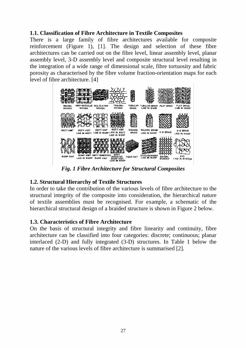
1.1. Classification of Fibre Architecture in Textile Composites There is a large family of fibre architectures available for composite reinforcement (Figure 1), [1]. The design and selection of these fibre architectures can be carried out on the fibre level, linear assembly level, planar assembly level, 3-D assembly level and composite structural level resulting in the integration of a wide range of dimensional scale, fibre tortuosity and fabric porosity as characterised by the fibre volume fraction-orientation maps for each level of fibre architecture. [4]
Fig. 1 Fibre Architecture for Structural Composites
1.2. Structural Hierarchy of Textile Structures In order to take the contribution of the various levels of fibre architecture to the structural integrity of the composite into consideration, the hierarchical nature of textile assemblies must be recognised. For example, a schematic of the hierarchical structural design of a braided structure is shown in Figure 2 below. 1.3. Characteristics of Fibre Architecture On the basis of structural integrity and fibre linearity and continuity, fibre architecture can be classified into four categories: discrete; continuous; planar interlaced (2-D) and fully integrated (3-D) structures. In Table 1 below the nature of the various levels of fibre architecture is summarised [2].

28
θbraid angle effect
φ
β
Crimp Effect
Fiber drawing effect
Yarn twist effect
Material Property
Fiber and Yarn Packing
Braid Helix Angle
Fig. 2. Structural Hierarchy of Fibrous Assemblies
Table 1. Fibre Architecture for Composites
Level Reinforcement
System Textile Construction
Fibre Length
Fibre Orientation
Fibre Entanglement
I Discrete Chopped Fibre
Discontinuous Uncontrolled None
II Linear Filament Yarn
Continuous Linear None
III Laminar Simple Fabric
Continuous Planar Planar
IV Integrated Advanced Fabric
Continuous 3-D 3-D

29
2. The Role of Fibre Architecture in Improving Structural Integrity
• Delamination Resistance [3]
• Structural Toughening of Ceramic Matrix Composites [6]
• Impact Damage Resistance – low and high velocity impact [7]. By placing the strong and stiff SCS filaments in the axial (0°) direction in the 3-D braided Nicalon fibre network, significant improvements in tensile strength as well as first cracking strength were achieved in the SiC/SiC/LAS III structure (Figure 3). It is remarkable to observe that the elongation to break of the hybrid composites also increases with the increase of the proportion of SCS filaments, resulting in a much strengthened and toughened CMC [6].
Fig. 3. Tensile Stress-Strain Behavior of 3-D Braided SiC/LAS III Composites [6]
30
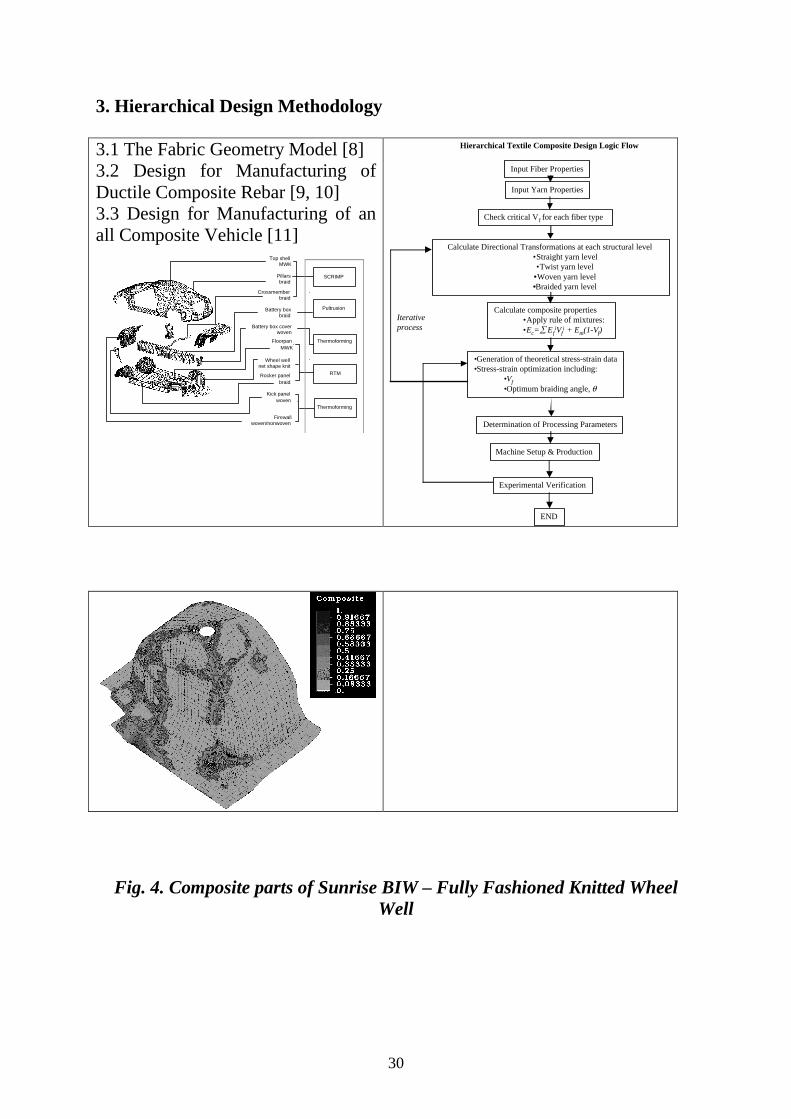
3. Hierarchical Design Methodology 3.1 The Fabric Geometry Model [8] 3.2 Design for Manufacturing of Ductile Composite Rebar [9, 10] 3.3 Design for Manufacturing of an all Composite Vehicle [11]
Top shell MWK
Crossmember braid
Battery box braid
Wheel well net shape knit
Battery box cover woven
Pillars braid
Firewall woven/nonwoven
Floorpan MWK
Rocker panel braid
Kick panel woven
SCRIMP
Pultrusion
Thermoforming
RTM
Thermoforming
Input Fiber Properties
Input Yarn Properties
Check critical Vf for each fiber type
Calculate Directional Transformations at each structural level•Straight yarn level•Twist yarn level
•Woven yarn level•Braided yarn level
Calculate composite properties•Apply rule of mixtures:•Ec=∑ Ef
iVfi + Em(1-Vf)
Iterative process
Determination of Processing Parameters
Machine Setup & Production
Experimental Verification
END
•Generation of theoretical stress-strain data•Stress-strain optimization including:
•Vf•Optimum braiding angle, θ
Hierarchical Textile Composite Design Logic Flow
Fig. 4. Composite parts of Sunrise BIW – Fully Fashioned Knitted Wheel Well
31
4. Future Direction in Hierarchical Fibre Architecture Design • Modelling after natural systems – extending to the nanometer size
scale
• Nanocomposite – the implication of nanofibres and fibrous structures
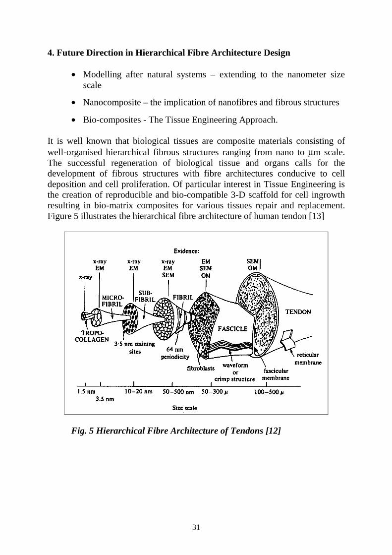
• Bio-composites - The Tissue Engineering Approach. It is well known that biological tissues are composite materials consisting of well-organised hierarchical fibrous structures ranging from nano to µm scale. The successful regeneration of biological tissue and organs calls for the development of fibrous structures with fibre architectures conducive to cell deposition and cell proliferation. Of particular interest in Tissue Engineering is the creation of reproducible and bio-compatible 3-D scaffold for cell ingrowth resulting in bio-matrix composites for various tissues repair and replacement. Figure 5 illustrates the hierarchical fibre architecture of human tendon [13]
Fig. 5 Hierarchical Fibre Architecture of Tendons [12]
32
5. Summary and Conclusions There is a large family of textile structures available for composite reinforcement. As advanced databases and analytical techniques become available, it is envisioned that textile structures will be adopted for structural applications. Experimental evidence shows that delamination failure mode of composites can be suppressed by through-the-thickness reinforcement introduced by stitching or Z-pinning. Hybridisation of material and fibre architecture results in significant improvement of first cracking strength and fracture toughness. Under drop weight impact, fully integrated fibre architecture such as 3-D braided composite have been demonstrated to be superior to laminated composites in damage containment and compression after impact strength. The judicious selection and exploitation of the unique characteristics provided by various fibre architectures calls for a thorough understanding of the hierarchical arrangement of the structural components in a textile structure. This is facilitated by the hierarchical modelling of textile composites as illustrated in the case of the braidtruded composite rebars and the composite wheel wells for the Sunrise composite vehicle. As we examine new directions for composites and the future role of fibre architecture plays in composite structural integrity, we were not surprised to find that nature’s bio-composite systems provides an excellent model for hierarchical design down to the nanometer fibre level. To this end, nanoscale fibres and methods have been developed to convert these nanofibres to higher order structures. Initial studies showed that these nanofibres and fibrous structures could be used effectively as scaffolds for the engineering of biological tissues. It is therefore, of interest to know: • What other roles can these nanofibrous structures play in the development of
multifunctional composites?
• How can we take advantage of nanofibres in nanocomposite design and fabrication?
• And how do we engineer composite products with these nanofibre architectures?
6. References 1. Ko, F.K., "Preform Fibre Architecture for Ceramic Matrix Composites,"
Ceramic Bulletin, February, 1989. 2. Scardino, F.L., An Introduction to textile Structures and their Behavior”, in
Textile Structural Composites, Chou, T.W., and Ko, F.K., eds., Elsevier, 1989.

33
3. Ko, F.K., Three Dimensional Fabrics for Composites, in Textile Structural Composites, Chou, T.W., and Ko, F.K., eds., Elsevier, 1989.
4. Ko, F.K., and Du, G.W., “Processing of Textile Preforms,” in Chapter 5. Advanced Composites Manufacturing, T.G. Gutowski, ed., Wiley Interscience, 1997.
5. Ko, F.K., “Chapter 1: 3-D Textile Reinforcements In Composite Materials,” 3-D Textile Reinforcements In Composite Materials, A. Miravete, editor, CRC Press and Woodhead Publishing1999.
6. Ko, F.K., Koczak, M., and Layden, G., "Structural Toughening of Glass Matrix Composites by 3-D Fibre Architecture," Ceramic Engineering and Science Proceedings, American Ceramic Society, Vol. 8, No. 7-8, July-August 1987.
7. Ko, F.K. and Hartman, D., "Impact Behavior of 2-D and 3-D Glass/Epoxy Composites," SAMPE Journal, Vol. 22, No. 4, July/August 1986, pp. 26-30.
8. Pastore , C.M. and Ko , F.K., "Modeling of Textile Structural Composites-Part 1: Processing Science Model for Three-Dimensional Braiding," Journal of the Textile Institute, Volume 81, Number 4, 1991.
9. Somboonsong , W., Ko , F.K. and Harris , H. G., “Ductile Hybrid Fibre Reinforced Plastic Reinforcing Bar for Concrete Structures: Design Methodology,” Journal of the American Concrete Institute, Volume 95, Number 6, 1998, pp. 655
10. H. G. Harris, W. Somboonsong and F.K. Ko, “New Ductile Hybrid FRP Reinforcing Bar for Concrete Structures”, Journal of Composites for Construction, February, 1998, p 28
11. Ko , F.K.., van Vuure , A.W., and Balonis , R.J., Textile Preforming for Complex Shape Structural Composites, SAMPE Journal, Vol. 35, No. 3, May/June 1999
12. Kastelic, J., Galeski, A., and Baer, E., “Structure and Function of Mammalian Tendon,” Journal of Connective Tissue Research.. , 6, 1978, pp.11-23
13. Ko, F K., Laurencin, C. T.,. Borden, M.D and Reneker, D., “The Dynamics of Cell-Fibre Architecture Interaction,” Proceedings, Annual Meeting, Biomaterials Research Society, San Diego, April, 1998.
14. Borden, M., Attawia, A., Ko, F. and Laurencin, C., "Fabrication of a Porous Polymer-Ceramic Implant for Use in Bone Regeneration," Journal of Orthopedic Research, to be published.
15. Laurencin, C.T., Ko, F.K, Attawia, M.A and Borden, M.D., "Studies on the Development of a Tissue Engineered Matrix for Bone Regeneration, Cells and Materials," Scanning Microscopy International, Chicago, 1998.
16. Ko, F K., “Three Dimensional Fibrous Scaffolds for Tissue Engineering,” proceedings, NATO Workshop, Poznan, Poland, June 23, 1999.
34
Towards a Methodology to Assess the Structural Integrity of Composite Structures
Paul A. Lagace and S. Mark Spearing
Technology Laboratory for Advanced Composites Massachusetts Institute of Technology,
Cambridge, Massachusetts, U.S.A.
Abstract The early introduction and use of composite materials in structural applications was dominated by the aerospace industry. It is therefore not surprising that the techniques that have evolved to design, certify, and assure structural integrity of composite structures are based on the methodologies of the aerospace world and even find some of their roots in methodologies used for metallic applications. However, the progression of the use of composite materials to a wide variety of applications, such as civil infrastructure, calls for adaptations and development of methodologies suitable for those particular applications with consideration given to a number of factors. These factors include the criticality of the application, the accessibility for inspection, the intended use including load and time, the manufacturing technique, and, of course, the particular material utilised. No one methodology can possibly encompass the wide variety of applications. Approaches can and do run the gamut from the relatively simple-minded make-and-break philosophy often used in consumer goods to the sophisticated building block approach practiced for composite aircraft structures. In looking towards various methodologies, one can identify several key parts common to the overall processes: design, production, and maintenance and repair. Superposed on these three parts is an item that runs throughout -- assessment. This includes physical assessment of the structure and the evaluative assessment of the current structural integrity. A key linking concept that runs through these is damage. It is the development, growth, and sensitivity of damage in a structure and the associated ability to assess the level of damage in a structure and its effect on structural performance that shapes the overall design of a particular structure. Although identified as separate, these parts of the processes must be considered in an integral fashion in the development of the structure through the issue of damage in order to best address the pertinent needs and thereby achieve the goal of efficient, cost-effective designs. Two keys to achieving such efficient and cost-effective designs are to fully utilise the ability to tailor composite

35
performance by choice of fibre, matrix, architecture, and associated processing, and to be able to iterate on the design rapidly and accurately in order to address emerging considerations in the global marketplace such as time-to-market. The current design methodologies, particularly in regard to assuring structural integrity, tend to be slow, excessively cumbersome, and often struggle to reach a satisfactory, let alone good, design. The underlying cause of these shortcomings is the empirical nature of the current design methodologies in dealing with the critical issue of damage. An overall design framework is proposed based on linking the behavior of composite material systems at various levels and lengthscales from the fibre, matrix, and associated interface/interphase (micromechanics) to the full-scale structure (structural macromechanics), specifically in regard to the two issues of the ability of a structure to undergo an event without the occurrence of damage (damage resistance) and the ability of a structure to perform with damage present (damage tolerance). The capability of existing models is assessed within this context and suggestions are made as to how to proceed from the current base of methodologies dominated by empiricism to ones which are more soundly based on mechanism-based models integrated with timely experiments. The development of the proposed design methodology framework must be evolutionary and will have short- and long- term benefits ranging from improvements in test programs to concentrate on critical damage and failure modes, damage scenarios, and key lengthscales, thereby reducing the need for extensive and costly testing; to making more options available to the designer, thereby leading to more versatile, more cost-effective, and more efficient composite products.

36
Some remarks on the Structural Integrity Prediction of Construction Elements built-up with
Polymer Matrix Composites
Albert H. Cardon and Pascal Bouquet Dept. Mechanics of Materials and Constructions
Faculty of Applied Sciences and Engineering (TW) Free University Brussels (VUB) Pleinlaan 2 – 1050 Brussels ,
Belgium (EU) Abstract Polymer matrix composites exhibit global and local time dependent effects. Under a complex mechanical loading history in interaction with environmental variations, the development of damage results in some time dependent failure process. Damage and failure has to be defined for any specific application. The analysis of the thermomechanical behaviour of the chosen material system, including the processing conditions, must allow us to define acceptable stress levels and admissible loadings in order to predict the conditions for safe structural integrity of the construction element. Those conditions will give us the necessary informations for the design of the construction component including the choice of the constitutive materials on micro- and mesoscale level : fibres, matrix, stacking sequences and the optimal processing conditions. Different prediction methodologies were developed over the last decennia. Those methodologies will be presented, discussed and compared. Non of those prediction methods, especially in relation to the processing conditions, give satisfactory results. Only the combination of the basic elements of some of those prediction methodologies can allow us to arrive at design conditions for a safe residual structural integrity after a given loading history under changing environmental variations for an imposed life time. It is my intention to give some provocative overview of the different theoretical, numerical and experimental aspects related to the prediction of life time, durability, structural integrity and reliability analysis for different types of applications where time dependent material behaviour is present in a structural component. I start at the micro-level: fibres, matrix and the degree of interaction; over the mesoscale level of the unidirectional layer, in relation to the design aspects and the curing conditions; and to the first macro-level of the laminate and the second macro-level, or level of constructions under loading.

37
In the case of short fibres the path is going from micro-level to macro-level one related to design aspects and processing conditions. We also discuss the need of the statistical analysis of the experimental results and the possible choice between some limit criteria, a damage analysis or a combination of both.

38
Pre-stress Applications in Composite Structures
George J. Dvorak CCMS-5003 JEC
Rensserlaer Polytechnic Institute Troy, USA
Abstract This presentation will describe the effect of prestressing fibres prior to matrix cure, and releasing the prestress forces after matrix consolidation, on residual stresses in selected composite structures. The overall goal of this research is to use release of fibre prestress in damage control and failure prevention, by designing optimal prestress distributions that cause damage-retarding residual stresses. Fibre prestress is often used to reduce fibre waviness in structures loaded in compression, and is routinely applied during filament winding or fibre placement. Small forces applied to fibre tows result in relatively large prestress magnitudes. In laminated plates, the effect of prestress removal on the residual stresses in the matrix and fibre is visualised in initial damage maps consisting of critical stress branches that satisfy ply failure criteria. It is shown that significant improvement in damage resistance can be obtained in selected loading ranges of the laminates. Effect of fibre prestress on free edge stresses is also examined. It is shown that release of optimised prestress distributions reduces the unfavourable free edge stresses caused either by mechanical loading or by thermal changes. In laminated cylinders under external pressure, we identify both favourable and unfavourable prestress distributions through the cylinder wall , and their effect on residual stress states.
39
Key Research Issues in the Bonded Composite Repair of Metallic Aircraft Structures
Alan Baker
Airframes and Engines Division, Defence Science and Technology Organisation,
Aeronautical and Maritime Research Laboratory, Australia. Summary The availability of efficient cost-effective technologies to repair or extend the life of ageing military airframes is becoming a critical requirement in most countries around the world, as new aircraft become prohibitively expensive and defence budgets shrink. Adhesively bonded composite reinforcements can be used to extend airframe life by bridging cracks and/or reducing strain levels. Compared to conventional procedures, this technology is highly efficient and cost effective; in some cases it is the only alternative to retiring the component. To date the reinforcement technology has resulted in documented savings of many hundreds of millions of dollars in Australia alone and is becoming well established worldwide. However, further R&D is required to fully exploit composite reinforcement, particularly when applied to flight-critical structure. For example, in primary single-load-path structure suffering fatigue cracking it is not currently possible to give credit to [certify] the patch for restoring residual strength and reducing the rate of crack growth, mainly because of uncertainties with bond durability and failure modes. Thus inspection intervals must be based on the crack-growth rate for the unpatched structure. Recently, three major reviews were undertaken to define the general R&D needs of bonded composite repair technology. These reviews were by the Committee on Ageing of US Airforce Aircraft in 1997, the Technical Cooperation Program (TTCP) Aeronautical Vehicles Action Group on Certification on Bonded Structure in 1999 and an Australian Defence Science and Technology (DSTO) strategic review by the author and colleagues in 1998. This paper examines some of these recommendations on the basis of the status of the current R&D and makes detailed proposals for future studies.

40
Focus of the paper is on issues related to certification. These are discussed under the major headings of: 1) Acquisition of Design Data, including of loads and load spectra and of materials allowables based on the correct failure modes and damage criteria; 2) Validation of Design Procedures, including testing of design models and risk assessment for bond durability 3) Risk Mitigation, including the “smart patch” approach. Issues related to increasing the scope of the technology are also discussed under the major headings of: 4) Design Capability, improved design models and 5) Materials and Processing, improved adhesive and composite systems designed for repair applications. Whilst the discussion in the paper is aimed at R&D issues for bonded repair technology many of the topics are equally highly relevant to the manufacture of composite airframes by adhesive bonding.
41
Adhesively Bonded Carbon/Epoxy Composite Patch Repair of Aluminium Alloy Aircraft Structures
P Poole
DERA, Farnborough, UK Abstract UK applications of adhesively bonded carbon/epoxy patches for the repair of metallic aircraft structures will be reviewed briefly. Most of these repairs have concerned cracked secondary structures on RAF aircraft, although a few involved primary structures repaired on a Special Trial Fit basis. In addition, bonded composite patches have been used to repair successfully a helicopter full scale fatigue test specimen, and design studies at British Aerospace have indicated the suitability of bonded patches for a range of airframe repairs. Recent theoretical and experimental research at DERA on bonded composite patch repair of cracked aluminium alloy structures will be summarised, with particular reference to investigations of the influence of in-service variables on patch efficiency. Investigations of the effects of the following variables on patch efficiency will be described:
• Effects of bondline defects
• Effects of impact damage
• Effects of service temperature
• Effects of long term environmental exposure. For selected studies, the observed efficiency of patches in retarding the growth of fatigue cracks will be compared with theoretical predictions based on a 3-dimensional boundary element/finite element model. The importance of residual thermal stresses, debonding and out-of-plane bending will be indicated, and the ability of the model to predict the effects of selected variables on patch efficiency will be considered. In addition, ongoing research to assess the potential of bonded patches for the repair of (1) battle damage, and (2) corrosion damage, will be outlined. Finally, current problems and future research requirements will be summarised.
42
Modelling Matrix Properties for Predictions of Durability in Polymer Composites
F R Jones and V Gumen
Department of Engineering Materials, University of Sheffield, Sir Robert Hadfield Building, Mappin Street, Sheffield S1 3JD
Abstract The durability of a fibre composite is mostly determined by the long term properties of the polymeric matrix. Thus for aerospace materials much effect is spent on assessing moisture absorption and its effect on the glass transition temperature. Unfortunately the non-equilibrium nature of the thermosetting resin network can lead to non-fickian diffusion and a definite thermal spike enhancement which makes long-term predictions rather difficult (1). Furthermore, the moisture also leads to the formation of a number of peaks in the thermal mechanical spectrum, which are also mirrored in the matrix expansion coefficient (2). As a result thermal cycling enhances the potential for transverse cracking of all plies, through the induction of significantly higher transverse thermal strains (3). These also affect the first ply failure criterion of a composite laminate under load and as a result the design strain of a structure. For similar reasons durability under fatigue leading is strongly dependent on the matrix properties. One way of controlling transverse properties of a lamina is through interfacial design. It would be better to achieve perfect bonding and allow yield (instead of debonding) to occur within a thin inter-phase region, to provide load dissipation when interfacial cracks and fibre breaks occur (4). In order to design these aspects into a composite a good predictive model of relevant matrix properties under hygrothermal conditions is required. It then becomes practical to design the inter-phasal and matrix resins for the correct long-term properties. Polymeric matrices for fibre composites are often blends of more than one thermosetting resin (e.g., epoxy resin) and of a thermoplastic which phase separates to a morphology which provides improved fracture toughness. The other requirement of the thermoplastic is to dilute the moisture absorbing thermoset and therefore reduce the affect of moisture and ageing at different temperatures. However, secondary relaxation peaks can develop on moisture absorption (5), leading to amplification in residual stresses in laminates.

43
Group Interaction Modelling (GIM) (6) has been used to predict the thermo-mechanical response of a thermoplastic-thermoset polymer blend, which consists of a blend of epoxy resins and polyethersulphone. This is the basis of a commercial epoxy resin used for pre preg which has been shown to exhibit the above phenomena. The GIM method is an energy balance of intermolecular forces and by introducing a degree of freedom, the contribution of the differing components of the polymer chain and cross-link density can be incorporated. Thus a glass transition temperature for the various epoxy components and PES have been calculated. On moisture absorption the individual chain components (from reaction with curing agents and the linear thermoplastic) have differing sensitivities and exhibited differing reductions in Tg. Thus, the experimentally observed splitting of the relaxation peak (Tg) can be predicted. Using an estimate of the Tg peak-width from the calculated average molar volume for each component a full thermo-mechanical envelope can be obtained from a series of gaussian curves. Thus, the effect of water on the relaxation peak for the polymer blend has been calculated and compared to experimental data for a commercial matrix system. The model has been validated by comparing the GIM predictions with experimental values for the base resins as shown in Table 1 (7). From predictive equations of Van Krevelen and Bicerano a new approach was developed to analyse the thermal behaviour of dry resin blend from the experimental DMTA relaxation curve. Such calculation can predict the order at which different regions of a macromolecular chain will undergo strain deformation at temperatures near Tg. The models are currently being used to predict the expansion coefficients and moduli of wet and dry resins, from which the thermal strain in a laminate can be calculated and compared with experimental measurement. With estimates of the maximum moisture absorption for a particular resin blend and/or laminate, the diffusion constant can be more quickly estimated from the first half-life, allowing precise predictions of time dependent phenomenon such as micro-crack potential to be gained.
Table 1. Predicted and Experimental Glass Transition Temperature of Investigated Resin Systems
MY0510-DDS Resin
Type 36wt% DDS
45wt% DDS
MY0510-DICY MY721-DDS MY721-DICY 924-epoxy
CTg cal °, 283 268 213 281 249 241
CTg °,exp 285 276 218 288 258 234
44
The Combined Influence of Damage and Environment on the Structural Integrity of Composite Structures:
A Methodology for Predicting the Residual Lifetime of Damaged Strictures.
P J Hogg, F C Smith, S Aramah and A Yoosefinejad
Department of Materials, Queen Mary and Westfield College, Mile End Road, London E1 4NS
Abstract A key question asked by plant engineers when faced with a damaged component in a process plant or structural system in general, is "Is it safe to leave the component in service or should it be replaced immediately". If it can be left in service can this be an indefinite reprieve or should the part be replaced at some future point, and if it can continue to be used can it still operate to its design specification.” This question is difficult to answer under the simplest of operating conditions, but a considerable body of research has been directed to providing sufficient information for sensible judgements to be made. However, an additional complication arises if the component has been exposed to aggressive environments during its service life, such that the materials properties changed over time even before a separate damage event occurred. Service damage can take many forms with perhaps the most serious being impact damage which consists of a local zone of micro-cracking, including delamination, fibre breakage, transverse and shear cracks. The consequence of that local area of intense damage is different according to the nature of the stress field experienced by the part. In compression some impact damage may be of little consequence unless significant fibre breakage occurs. However delaminations provoke an early failure in compression due to local instability. Many approaches to assessing the effect of damage can be based on simple attempts to allow for local stress raisers such as holes. The Whitney-Nuismer approach to predicting the effect of holes is based on largely empirical curve fitting exercises which provide a good route to predicting the structural integrity of a plate with a hole and a characteristic damage parameter, do or ao. The approach in this work has been firstly to determine if a Whitney-Nuismer analysis can be applied to all loading modes –tension, compression and shear, and to examine if the method works with impact damage instead of holes.

45
Subsequently the analysis has been extended to composite where the materials have experienced exposure to an aggressive environment both before and after the impact damage. This final development makes it possible to determine a relationship between a damage parameter and time of environmental exposure. Once this has been done it will be possible to assess the structural integrity of structures after combinations of environmental attack and impact damage. Furthermore, if it becomes possible to link a damage parameter to a local change in stiffness then it might be possible to introduce a method of inspecting the structural integrity of a part in-service without always knowing the exact environmental history of the part. To date testing and modelling have been undertaken on glass fibre composites with a variety of fibre orientations and forms, including woven fabrics and a variety of non crimp fabric styles, combined with epoxy, vinyl ester, phenolic and polyester resin systems. Testing was performed at elevated temperatures from 40- 93 C for up to one year and longer tem tests are currently under test. The Whitney-Nuismer analysis has been successfully used for compress and shear and has been applied with mixed results to describing the effects of impact damage. In some instances it has been found that the damage parameters do not change with environmental exposure, particularly in tension, whereas in compression the damage parameters are no longer so good at describing the damage state after the environment has modified the material. Alternative approaches to accommodating the effects an aggressive environment under compressive loading are being considered. The concept of equating damage with a reduction in local stiffness in order to predict residual strength has been tested by using composites with built-in inserts of different stiffness. A good correlation between residual properties and insert stiffness has been found. At present information from a wide range of materials systems is being collected and correlated in order to develop a broad methodology suitable for predicting the structural integrity of parts after extended environmental attack.

46
The Role of the Interfacial Stress State on the Durability of Polymer-Based Composites Systems
Y. Leterrier, D. Mendels, J.-A. E. Manson
Laboratoire de Technologie des Composites et Polymeres (LTC) Ecole Polytechnique Federale de Lausanne (EPFL)
CH-1015 Lausanne, Switzerland Abstract The combination of polymer materials with other materials into complex systems (multi-phase polymer composites, micro-electro-mechanical systems-MEMS) offers a number of key advantages over alternative bulk materials, such as lightweight, complex shape and design freedom, as also cost-effectiveness, together with unique mechanical, electrical and optical functions. However, the benefits of such increased material integration are considerably reduced by the lack of long-term stability the system, specifically due to uncontrolled levels of internal stresses inherent to the multi-material assembly subjected to dramatic environmental conditions, which often lead to its premature failure. To investigate the role of the interfacial stress-state on the durability of polymer-based composites, theoretical analyses of coupling effects between time-dependent processes are developed in a first step. These include the relaxation of stresses in the visco-elastic polymer, and its structural recovery induced during the final cooling stage of the processing operation, and which manifests itself by a gradual densification of the polymer amorphous fraction. It is found that the latter densification phenomenon is negligible compared to the corresponding shift of the visco-elastic time spectrum. As a result, the relaxation of both internal stresses and externally applied stresses is considerably slowed down throughout the life of the polymer-based material. The implications of this change in internal stress state on interfacial adhesion is examined in a second step for a variety of multiphase polymer systems such as micro-composites, multi-layer composites, adhesive joints and micro-devices. Stress transfer analyses that include the above-mentioned coupling effects, together with finite element simulations, indicate that intrinsic adhesive strength is not modified by the structural recovery of the polymer phase. Moreover, it is shown that different interfacial or cohesive failure processes may be activated, depending on the mechanical behaviour of the polymer, on the geometrical features of the multiphase system and on ageing time. These analyses provide important insight on the role of process-induced internal stresses on long-term durability of polymer-based composites.
47
Management and Control of Interfacial Microstructure in Thermoplastic Matrix Composites for
Optimising Strength and Structural Integrity
Gad Marom Casali Institute of Applied Chemistry The Hebrew University of Jerusalem
91904 Jerusalem, Israel Abstract Because of its thickness, an interfacial layer between the fibre and the matrix should be considered as an additional, third phase in the composite material. Thus, its contribution cannot be analysed in terms of the interfacial strength with both of these constituents alone. Rather, its elastic and mechanical properties comprise essential design parameters to be included in the structural analysis and the engineering design. Correspondingly, the scientific literature contains examples of studies of soft or rigid interfacial layers and their different effects on the longitudinal properties of composite structures.
48
Evolution of Thermal Residual Stresses in Semi-crystalline Model Composites
Ryszard Pyrz
Institute of Mechanical Engineering, Aalborg University Pontoppidanstræde 101, 9220 Aalborg East, Denmark
Abstract Thermal stresses in a fibre reinforced composite are determined by the interaction between the solidifying matrix and the fibre. In composites with a semi-crystalline matrix solidification is associated with crystallisation. In semi-crystalline thermoplastic matrix composites trans-crystallisation often takes place. Trans-crystallisation occurs when spherulities are heterogeneously nucleated on the fibre surface. As the spherulities impinge they grow radially from the fibre forming the trans-crystalline interlayer. This phenomenon has been observed in several commercial matrices, e.g., PEEK, and other polymers. Polarised Raman microspectroscopy has been used to determine crystal orientation within the transcrystalline interlayer of a carbon/polypropylene matrix composite. The orientation distribution of the crystal chain segments was quantified in terms of spherical harmonics series expansion describing a general biaxial orientation distribution. The expansion coefficients were determined up to fourth order from polarised Raman scattering on three perpendicular planes. From the Raman scattering on samples subjected to varied thermal history a model of the conformational states within the microstructure of the polypropylene was proposed. This model is comprised of three phases: a crystalline phase, an isomeric defect phase and an amorphous melt like phase. Effective properties of the polymer can be predicted from the derived local response in terms of the parameters characterising the crystalline microstructure. Prediction of solidification and evolution of thermal residual stresses may thus be accomplished by a quantitative characterisation of the crystallisation kinetics. Having established a valid model for the thermal stress evolution, it is possible to determine the thermal stress distribution after cooling of the composite. Thermal stresses were measured in-situ during cooling. In semi-crystalline matrix systems cooling rate was found to have a pronounced effect on thermal stresses due to the rate dependence of the crystallisation as well as stress relaxation in the matrix. Theoretical predictions were compared to experimental results of thermal stresses and a close agreement was obtained.

49
Lifetime Modelling of Composites Used in Clinical Applications
Keya Sadeghipour, John McCool1, George Baran
College of Engineering, Temple University, Philadelphia, USA
Abstract Materials used to restore the function of diseased hard tissues such as teeth and bone must fulfill several demands imposed by the hostile environment of the human organism. The materials must be biocompatible, esthetic, and possess the ability to resist crack initiation and propagation. Composite materials typically present the materials engineer with an opportunity to design a satisfactory replacement. The loads exerted on restorative materials during mastication or walking are cyclical, and so the fatigue resistance of these materials is of concern. There is therefore a tendency to conduct fatigue testing during product development, although no laboratory tests can be reasonably extended to the several million cycle regime characteristic of a few years clinical use. Lifetime estimates are therefore based on crack propagation rate measurements. We have subjected epoxy matrix/glass particle reinforced composites to cyclic and dynamic fatigue testing. Although the matrix is elasto-plastic, load deflection data for the composites exhibit linearity, fracture strengths follow the Weibull distribution, and the composites exhibit a size effect. The constant N of the power law formulation for crack growth rate was calculated from fatigue data and used to calculate an equivalent static tensile stress for a five-year survival time. As is the case for brittle but multiphase ceramics, the two fatigue test modes do not yield equivalent crack growth constants or lifetime predictions: cyclic fatigue yields a more conservative prediction. Current modeling efforts are focused on finite element methods of predicting crack initiation locations, and the effects of the particle/matrix interface on crack propagation and toughening. 1Pennsylvania State University, Great Valley, PA

50
Bio-active Glass Polymer Composites in Tissue Engineering
A. Stamboulis and L. L. Hench
Department of Materials, Imperial College of Science, Technology and Medicine, Prince Consort Road, London SW7 2BP Abstract The term ‘bio-activity’ is used for materials that ‘elicit a specific biological response at the interface of the material which results in the formation of a bond between the tissues and the material’. Hench (1969) discovered the so-called bio-active glasses, that can bond chemically to bone. The main characteristic of these bio-active glasses is the formation of a hydroxycarbonate apatite layer on their surface in contact with any aqueous solution. This layer is the equivalent in composition and structure to the mineral phase of bone. Bio-active glasses have been used for the repair and reconstruction of diseased and damaged hard tissue such as bone as well as soft tissue such as ligament. The use of bio-active glasses in tissue engineering allows the control of a range of chemical properties and the rate of bonding to different tissues. The use of polymers in biomedical applications has been very important. Synthetic as well as natural polymers have been widely used as membranes, disposable medical equipment, sutures and adhesives (biodegradable and non-biodegradable), cardiovascular devices, orthopaedic implants, ophthalmic devices, dental restorative materials, degradable plastic commodity products etc. A class of polymers called ‘bio-degradable’ or ‘re-sorbable’ or ‘erodible’ is very interesting because it has two main advantages. First, they can be absorbed gradually by the human body without permanently retaining trace of residual in the implantation site; and second, they are able to regenerate tissues through interaction of their degradation products with immunologic cells such as macrophages. Successful applications require a full understanding of the environment experienced by cells in normal tissues and by cells in bio-artificial devices before and after implantation. Developing living tissue substitutes based on synthetic bio-degradable polymers holds a great promise in the field of tissue engineering. Poly-L-lactide acid, polyglycolic acid and their copolymers are the most well studied bio-compatible, bio-degradable polymers, which have been proved suitable substrates for many cell types. Novel synthesis and manufacturing techniques have been developed to give porous scaffolds with large void volumes for cell seeding and cell attachment.

51
The idea of developing polymer-glass or ceramic composites is not new. Ceramic materials alone do not posses the required mechanical properties to replace natural bone. The first bio-ceramic composites were designed to match the natural components of bone; hydroxyapatite (HA) and collagen. The mechanical properties of these composites were expected to being improved, however, results showed that the overall strength was reduced. Chemical bonding of the polymer to the bio-active phase would improve strength but degrade bio-activity. Consequently, the research was focused towards the augmentation of bone that allows the bone to grow and replace the material. This need has resulted in using re-sorbable polymer matrices such as collagen, hyaluronic acid, gelatine or other synthetic re-sorbable polymers such as polyglycolic acid, polylactic acid and their co-polymers. Injectable composites based on Bioglass and a polysaccharide such as dextran have been also developed. A recent development of the resorbable Bioglass/dextran composite system is the introduction of the material as a mouldable putty-like material. This paper deals with a review of the use of resorbable polymers combined with bio-active Bioglass particles for hard as well as soft tissue regeneration. A new approach of a resorbable polymer-bio-glass composite towards 3D composite structures will be described.
52
Modelling Microstructures in Composites
C. T. Sun School of Aeronautics and Astronautics, Purdue University
West Lafayette, Indiana 47907, USA Abstract Modern materials such as advanced fibre-reinforced composites are often heterogeneous at the micro scale level. Their macro continuum properties are evidently closely related to their microstructures. It is conceivable that by tailoring the microstructure, design materials for specified functions are possible to realise. In such a technology endeavour, the most fundamental aspect of research is a thorough understanding of the effects of microstructures on the macro properties. Techniques used in obtaining composite properties from it constituents are usually termed micro-mechanics which has attracted the attention of numerous researchers. Volume fractions of the constituents have been taken as the most important parameter in the microumechanics analysis of composites. To illustrate the effect of other microstructural characteristics on the properties of the composite, let us consider the new co-continuous composites that have very different microstructures than the conventional fibrous and particulate composites. For example, a number of co-continuous metal ceramic composites have been developed at Purdue University. These new composites differ from the conventional metal matrix composites in that both constituent phases in these new materials are contiguous while in conventional metal matrix composites one phase is suspended in the matrix phase. Figure 1 shows the microstructure of a commercially available 6092 Al/SiC (25%) silicon carbide particle/aluminum alloy matrix composite. The SiC particles (the dark regions) are not connected to each other. On the other hand, the aluminium/alumina (about 30% alumina) co-continuous composite has two contiguous phases. The Al/alumina composite was processed using a preform made with atomised wax and ceramic slurry (in order to have perfect spherical pores inside ceramic sponge). The wax was vapourized by pyrolisis at 5500C. Then the ceramic was sintered at 16000C for 4 hrs. This preform was coated with NiAl2O4 for complete wetting. Subsequently, pure aluminium was infiltrated at about 12500C inside the furnace. Because of this processing method, both constituent phases are contiguous. The content of pure aluminium in this composite is approximately 70%.
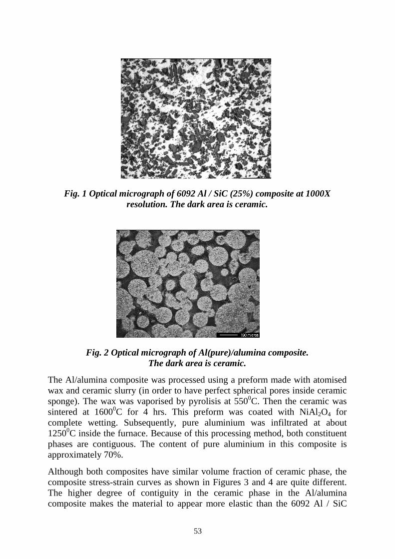
53
Fig. 1 Optical micrograph of 6092 Al / SiC (25%) composite at 1000X
resolution. The dark area is ceramic.
Fig. 2 Optical micrograph of Al(pure)/alumina composite.
The dark area is ceramic.
The Al/alumina composite was processed using a preform made with atomised wax and ceramic slurry (in order to have perfect spherical pores inside ceramic sponge). The wax was vaporised by pyrolisis at 5500C. Then the ceramic was sintered at 16000C for 4 hrs. This preform was coated with NiAl2O4 for complete wetting. Subsequently, pure aluminium was infiltrated at about 12500C inside the furnace. Because of this processing method, both constituent phases are contiguous. The content of pure aluminium in this composite is approximately 70%.
Although both composites have similar volume fraction of ceramic phase, the composite stress-strain curves as shown in Figures 3 and 4 are quite different. The higher degree of contiguity in the ceramic phase in the Al/alumina composite makes the material to appear more elastic than the 6092 Al / SiC
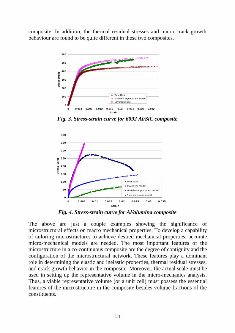
54
composite. In addition, the thermal residual stresses and micro crack growth behaviour are found to be quite different in these two composites.
Fig. 3. Stress-strain curve for 6092 Al/SiC composite
Fig. 4. Stress-strain curve for Al/alumina composite The above are just a couple examples showing the significance of microstructural effects on macro mechanical properties. To develop a capability of tailoring microstructures to achieve desired mechanical properties, accurate micro-mechanical models are needed. The most important features of the microstructure in a co-continuous composite are the degree of contiguity and the configuration of the microstructural network. These features play a dominant role in determining the elastic and inelastic properties, thermal residual stresses, and crack growth behavior in the composite. Moreover, the actual scale must be used in setting up the representative volume in the micro-mechanics analysis. Thus, a viable representative volume (or a unit cell) must possess the essential features of the microstructure in the composite besides volume fractions of the constituents.
0
100
200
300
400
500
600
0 0.004 0.008 0.012 0.016 0.02 0.024 0.028 0.032Strain
Stre
ss (M
pa)
Test DataModified eigen strain modelLayered model
0
50
100
150
200
250
300
350
400
0 0.005 0.01 0.015 0.02 0.025 0.03 0.035Strain
Stre
ss (M
Pa)
Test data
Two layer model
Modified eigen strain model
Pure aluminum metal

55
Micro/Macro Scale Modelling of Progressive Damage in Composites
Young W. Kwon
Mechanical Engineering Department Naval Postgraduate School, Monterey, California, USA
Abstract A multi-scale modelling approach was developed for design and analysis of composite materials (structures) in various engineering applications. The approach is based on bilateral relationships among micro- and macro-scales of a composite. The micro-scale denotes the constituent material level like reinforcing fibres and particles, and binding matrix materials while the macro-scale indicates the level of smeared composite materials (structures). The number of levels in the macro-scale of composite materials (structures) is different depending on the type of composites. For a particulate composite, there is one level of the macro-scale. For a fibrous composite, there are two macro-scale levels: one for a unidirectional lamina and the other for a laminated composite. On the other hand, a woven fabric composite can have three macro-scale levels: a unidirectional strand, a woven fabric, and a laminated woven composite. Among them, the woven fabric composite has the most general structure of material organisation, and others can be a subset of the woven fabric composite. As a result, the multi-scale computational model for a woven fabric composite is illustrated in Fig. 1. In the multi-scale technique, smeared composite properties are computed using three sequential modules as shown in the figure, starting with the micro-scale properties and geometry such as the fibre and matrix properties and their volume fractions. The smeared properties are used for the finite element analysis at the structural level to compute stresses, strains, and deformations. These are the quantities at the composite structural level. These values are decomposed into a lower level (i.e., to a left side of Fig. 1) using the three modules. Eventually the stresses and strains at the fibre and matrix level are computed. Damage/failure criteria are applied at this level. Therefore, damage/failure in any complex composite structure can be analysed at the most fundamental level and in the simplest modes. At the micro-level, damage/failure modes are classified as fibre breakage/buckling, matrix cracking, and fibre/matrix interface debonding. These damage modes can describe various damages at the macro level.
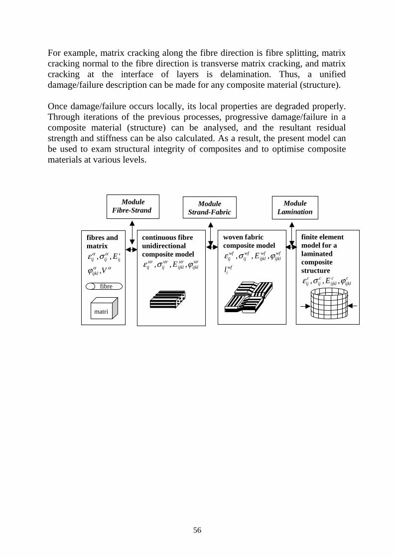
56
For example, matrix cracking along the fibre direction is fibre splitting, matrix cracking normal to the fibre direction is transverse matrix cracking, and matrix cracking at the interface of layers is delamination. Thus, a unified damage/failure description can be made for any composite material (structure). Once damage/failure occurs locally, its local properties are degraded properly. Through iterations of the previous processes, progressive damage/failure in a composite material (structure) can be analysed, and the resultant residual strength and stiffness can be also calculated. As a result, the present model can be used to exam structural integrity of composites and to optimise composite materials at various levels.
fibres and matrix ε σ
ϕ
α α α
α α
ij ij ij
ijkl
E
V
, ,
,
continuous fibre unidirectional composite model ε σ ϕij
strijstr
ijklstr
ijklstrE, , ,
woven fabric composite model ε σ ϕij
wfijwf
ijklwf
ijklwf
iwf
E
l
, , ,
finite element model for a laminated composite structure ε σ ϕij
cijc
ijklc
ijklcE, , ,
Module Fibre-Strand
Module Strand-Fabric
Module Lamination
fibre
matri

57
Life Prediction for Composite Materials Under Multiaxial Fatigue Loadings
M Quaresimin° and L Susmel*
°Department of Management and Engineering University of Padova, Vicenza, Italy
*Department of Mechanical Engineering, University of Padova Abstract The continuous increase in the application of composite materials in structural engineering systems requires the developments of safe and reliable design rules; moreover, during the service life the structural composite components are usually subjected to complex multiaxial loading. Although the development of general design rules for uniaxial loading conditions is still very far from close, it is important to analyse the problem even from a multiaxial standpoint with the ambitious aim to unify, if possible, the design methodologies. The paper presents a re-analysis of about 700 experimental literature data related to multiaxial fatigue testing and a comparison of the life prediction obtained by means of some of the available models. On the basis of the literature data, the influence of several design parameters on the multiaxial fatigue strength has been investigated: in particular, the off-axis angle, the biaxiality ratios λ1=σ2/σ1 and λ2=σ6/σ1 , the phase angle δ between the applied stress components and the notch effects have been considered. Some results are shown in Figures 1 and 2.
10
100
1000 10000 100000 1000000
Nf [Cycles]
σσσσx,a
[MPa]
λ=2, [0/90]λ=2, [45/-45]λ=1, [0/90]λ=1, [45/-45]λ=.5, [0/90]λ=.5, [45/-45]
R=-1λ τ
σ= xy
x
10
100
1000 10000 100000
Nf [Cicli]
σσσσL,a
[MPa]
λ2=0.5, λ2=0.5, λ2=1, δ=λ2=1, δ=λ2=2, δ=λ2=2, δ=
k=9.2,σL,a∞=28.3 MPa, Tσ=1.223
k=10.3,σL,a∞=20.5 MPa, Tσ=1.238
k=9.6, σL,a∞=11.4 MPa, Tσ=1.382
λ1=0R=-1
Figure 1: Off-axis angle influence on glass/potube (data from ref.[1]).
Figure 2: Influence of λ2 and phase δ on thestrength of glass/polyester tubular specimenfrom ref.[1]).
The comparison of the life prediction models involved the polynomial functions based criteria, in particular the Tsai-Hill model extended to the fatigue analysis, as first
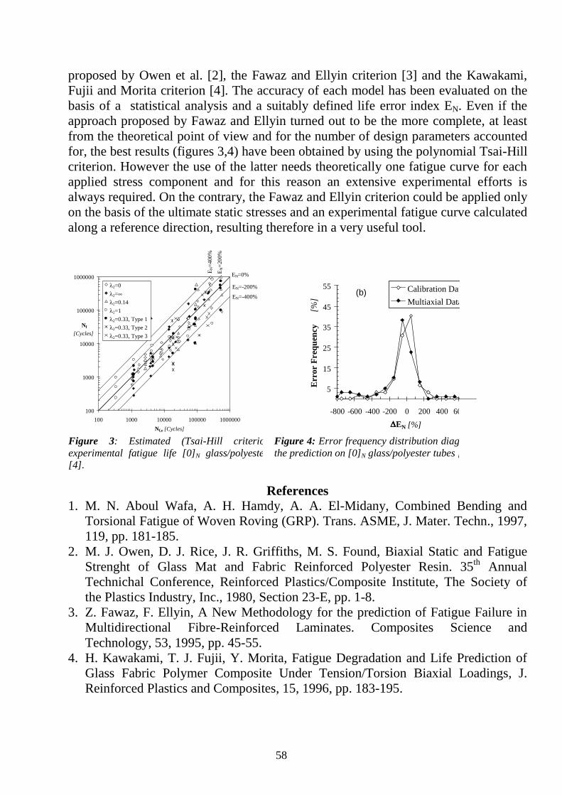
58
proposed by Owen et al. [2], the Fawaz and Ellyin criterion [3] and the Kawakami, Fujii and Morita criterion [4]. The accuracy of each model has been evaluated on the basis of a statistical analysis and a suitably defined life error index EN. Even if the approach proposed by Fawaz and Ellyin turned out to be the more complete, at least from the theoretical point of view and for the number of design parameters accounted for, the best results (figures 3,4) have been obtained by using the polynomial Tsai-Hill criterion. However the use of the latter needs theoretically one fatigue curve for each applied stress component and for this reason an extensive experimental efforts is always required. On the contrary, the Fawaz and Ellyin criterion could be applied only on the basis of the ultimate static stresses and an experimental fatigue curve calculated along a reference direction, resulting therefore in a very useful tool.
100
1000
10000
100000
1000000
100 1000 10000 100000 1000000Nf,e [Cycles]
Nf
[Cycles]
λ2=0λ2=∞λ2=0.14λ2=1λ2=0.33, Type 1λ2=0.33, Type 2λ2=0.33, Type 3
EN=0%
EN=-400%
EN=-200%
E N=4
00%
E N=2
00%
5
15
25
35
45
55
-800 -600 -400 -200 0 200 400 60∆∆∆∆EN [%]
Err
or F
requ
ency
[%]
(b) Calibration DatMultiaxial Data
Figure 3: Estimated (Tsai-Hill criterioexperimental fatigue life [0]N glass/polyeste[4].
Figure 4: Error frequency distribution diagthe prediction on [0]N glass/polyester tubes [
References
1. M. N. Aboul Wafa, A. H. Hamdy, A. A. El-Midany, Combined Bending and Torsional Fatigue of Woven Roving (GRP). Trans. ASME, J. Mater. Techn., 1997, 119, pp. 181-185.
2. M. J. Owen, D. J. Rice, J. R. Griffiths, M. S. Found, Biaxial Static and Fatigue Strenght of Glass Mat and Fabric Reinforced Polyester Resin. 35th Annual Technichal Conference, Reinforced Plastics/Composite Institute, The Society of the Plastics Industry, Inc., 1980, Section 23-E, pp. 1-8.
3. Z. Fawaz, F. Ellyin, A New Methodology for the prediction of Fatigue Failure in Multidirectional Fibre-Reinforced Laminates. Composites Science and Technology, 53, 1995, pp. 45-55.
4. H. Kawakami, T. J. Fujii, Y. Morita, Fatigue Degradation and Life Prediction of Glass Fabric Polymer Composite Under Tension/Torsion Biaxial Loadings, J. Reinforced Plastics and Composites, 15, 1996, pp. 183-195.

59
On Representing the Microstructure of Fibrous Composites: It’s Consequences in Mechanics Modelling
Albert S. D. Wang
Drexel University, Philadelphia, PA 19104 USA Abstract The major theme of this conference in Capri is optimisation of micro-structural design and structural integrity of composite materials and structures. It is thus fitting to examine, now critically, the connection between microstructure and structural integrity of fibre-reinforced composites. Specifically, we shall examine the prevailing practice of microstructure homogenisation as a basis for modeling composites in connection to their design and analysis under load. Microstructure Homogenisation has served as a keystone in the development of most of the prevailing structural theories for fibrous composites. The concept provides the necessary connection between the micro-level and macro-level descriptions of composites as a material. In general, micro-level description delineates the fibre and matrix phases explicitly – sometimes it also includes other identities such as defects. At the macro-level, the various phases are homogenised into a continuum, endowed with a set of effective properties that are commensurable to those in the actual composite at the micro-level. The two-level description is, of course, the key to developing any reliable design and analysis theory for load-bearing structures that are made of composites. In this context, the usual approach is to identify a representative volume element (RVE), endowed with a microstructure that is statistically similar to that in the actual composite, and to conduct a micro-mechanics analysis of the RVE in order to obtain the desired effective properties for the composite as a homogeneous material. In this regard, choice of the RVE with a realistic representation of the microstructure therein is essential. For the RVE must provide the desired effective properties of the homogenised composite so as to build upon it a reliable structural model at the larger scale; once the composite is analysed at the macro-level, it must also be capable of recovering the micro-level responses (e.g. stresses and strains) so as to see what and why failure initiates and grows. These are conflicting propositions inherent in the homogenisation concept; and the conflict remains unresolved ever since the concept was put in use for fibrous composites some four decades ago (e.g., since R. Hill and Z. Hashin). Consequently, there exist a number of dilemmas and paradoxes.

60
This paper shall review some of the prevailing RVE models, now routinely used in connection with composite laminates made of unidirectional fibre composite systems, and to discuss the inherent dilemmas and paradoxes - their sources and consequences. Illustrative examples with detailed results shall be used to reveal the nature of the problems from a physical point of view. At the macro-level, there also exist dilemmas and paradoxes brought by the very homogenisation concept itself. These problems emerge, for example, in connection with analysis of laminates, being made of individual lamina represented by homogenised continua with linearly elastic effective properties. If such laminates are analysed, as it is routinely done in practice, singular stress fields will be found at points where the laminate free edges intersect any of the layer interfaces; free-edge delamination may then emit from such points. As will be shown with specific examples, some of the singular fields do not exist at the micro-level at all; the encountered singularities are merely mathematical artifacts that are inherent in the homogenised model. On the other hand, at points where there exists no singularity at the macro-level, stress fields of high gradient may in fact exist at the micro-level; these, of course, actually dominate the formation of delamination. It is all understood that structural integrity of composites stems from its microstructure; and optimisation of micro-structural design is essential for an optimal structural performance. The connection between the two is built on the fundamental concept of microstructure homogenisation; for the down-stream mechanics and structural models are all based on this important concept. The dilemmas and paradoxes cited above remain not just as an academic curiosity; they bear serious consequences in practice as well; it is both academically challenging as well as practically important to examine the utility of this very concept at this Conference.
61
Understanding the Influence of Intrinsic Material Properties of Polymeric Materials through Modelling,
Simulation, and Test
Thomas S. Gates NASA Langley Research Center, Mechanics and Durability Branch
Hampton, VA 23681, USA
Abstract The exceptionally high cost and long lead time required for the development and insertion of new, advanced technology materials has made obsolete the “Edisonian” approach to materials research. Given a specific set of design requirements (e.g., strength, stiffness), this Edisonian approach relies on trial and error, serendipity, and experience to find the new materials that when scaled up from the laboratory level will possess the desired properties. Obviously, this approach is uncertain at best and can lead to a reliance on less than perfect materials that may result in conservative or compromised design. It is recognised that within the scope of materials and structures research the range of length and time scales may range more than 12 orders of magnitude, and different scientific and engineering disciplines are involved at each level. Despite the notable successes that have been achieved in each, an integrated approach has been lacking. This approach is one that draws from physics and chemistry, but focuses on constitutive descriptions of the materials that are useful in formulating macroscopic models. NASA Langley Research Center (LaRC) has established the Computational Materials program to address this issue and proposes it as the alternative to the Edisonian approach. The Computational Materials approach relies on recent, rapid increases in computer power and improvements in hierarchical models, experimental design, computational techniques, and simulation methods that open the way to the use of simulations in the development of new materials. At NASA LaRC, the Computational Materials program has concentrated on nanostructured materials including high performance polymers, carbon fibre composites, and nanocomposites made from polymers and carbon nanotubes. The emphasis of this research is to understand how the intrinsic properties of the material that can be controlled at synthesis contribute to the final, engineering level thermal/mechanical performance. The approach to the Computational Materials program is a set of integrated predictive models developed to bridge the time and length scales associated with prediction of material behaviour from the quantum through the meso scale. In addition to the models, critical experiments will be developed to provide
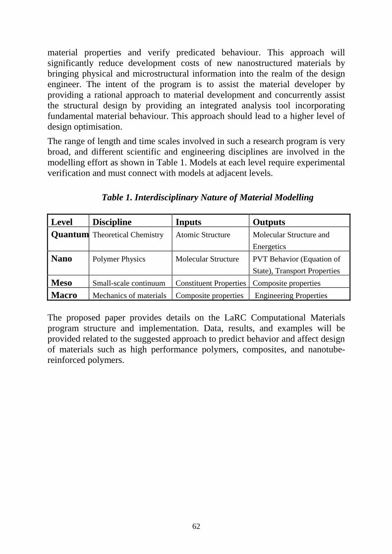
62
material properties and verify predicated behaviour. This approach will significantly reduce development costs of new nanostructured materials by bringing physical and microstructural information into the realm of the design engineer. The intent of the program is to assist the material developer by providing a rational approach to material development and concurrently assist the structural design by providing an integrated analysis tool incorporating fundamental material behaviour. This approach should lead to a higher level of design optimisation. The range of length and time scales involved in such a research program is very broad, and different scientific and engineering disciplines are involved in the modelling effort as shown in Table 1. Models at each level require experimental verification and must connect with models at adjacent levels.
Table 1. Interdisciplinary Nature of Material Modelling
Level Discipline Inputs Outputs Quantum Theoretical Chemistry Atomic Structure Molecular Structure and
Energetics Nano Polymer Physics Molecular Structure PVT Behavior (Equation of
State), Transport Properties Meso Small-scale continuum Constituent Properties Composite properties Macro Mechanics of materials Composite properties Engineering Properties
The proposed paper provides details on the LaRC Computational Materials program structure and implementation. Data, results, and examples will be provided related to the suggested approach to predict behavior and affect design of materials such as high performance polymers, composites, and nanotube-reinforced polymers.

63
Non-destructive Inspection of Bonded Composite Structures
Robert Crane
Nondestructive Evaluation Branch, Air Force Research Laboratory, AFRL/MLLP, 2230 10th Street, Suite 1, WPAFB, Dayton,
Ohio 45433-7817, USA Abstract There are a number of very efficient structural designs that utilise composite materials that have not received widespread acceptance because of inadequacies of one or more supporting technologies. For example, there is the reluctance of aircraft designers to use composites in some applications because of their lack of confidence in adhesive bonding as a primary joining technique. This paper will explore some misconceptions regarding older non-destructive inspection (NDI) techniques to predict bonded joints performance. Next, newer technologies that offer hope of providing realistic engineering data regarding joint performance will be presented. Finally, avenues for research in new NDI capabilities will be discussed. Areas to be discussed will include surface preparation, contamination, strength, and degradation during usage.

64
In Situ Micro Sensor Monitoring of the Performance Properties and Lifetime of Composite Structures
in the Use Environment
David E. Kranbuehl Departments of Chemistry and Applied Science
College of William and Mary, Williamsburg, Virginia 23185, USA Abstract This report focuses on the use of frequency dependent dielectric measurement sensors (FDEMS) and time of flight (TOF) molecular mobility sensing to monitor continuously, and in situ during use the changing state of a polymeric composite structure in the use environment. The results of feasibility studies using embedded FDEMS sensors to monitor both the changes in state-health of thermoplastic and thermoset composite systems used in rocket motors, composite pipes in deep sub-sea environments and satellites in atomic oxygen environments will be presented. Current life monitoring work focuses on characterising the chemical and physical processes occurring during ageing, using FDEMS and TOF sensors coupled with laboratory measurements of mechanical and thermodynamic properties to monitor the ageing rate and state of the polymer, and then integrating the sensor output with a model for predicting the remaining service life and state of the structure. Model predictions can be checked and are then periodically updated through the in situ online sensing measurements.
65
A Fatigue Limit and Apparently “Safe” Damage in CFRP Revealed by Acoustography
D P Almond, A S Chen and B Harris
Materials Research Centre University of Bath, Bath, BA2 7AY, UK
Abstract There are growing concerns about the effects of accidental impact damage on the structural integrity of aerospace composites and about the possible growth of the damage due to in-service fatigue. Damage monitoring in composite materials during fatigue has become possible by the emergence of a new ultrasonic imaging technology, acoustography. Acoustography is a broad area high definition ultrasonic imaging system that provides through thickness ultrasonic images of composites in near real-time. The successful integration of acoustography and a servo-hydraulic fatigue test machine has resulted in a new measurement system which can be used for the in-situ imaging of impact damage in composite specimens during long-term fatigue tests. Results obtained show damage area growth during compressive loading fatigue cycling that occurs in three stages. After an initial small enlargement, damage grows at a constant rate until the third stage is reached when damage grows with an increasing rate to final failure. However, a ‘fatigue limit’ has also been observed. At stresses below this fatigue limit, a zero damage growth regime has been found in studies of >106 fatigue cycles. The results obtained are believed to have important implications for the understanding of the effects of damage on fatigue life and for the design of ‘safe’ damage tolerant structures.

66
Design Optimisation Studies on Composite Pressure Vessels and Piping for Long Term Structural Integrity
W. M Banks, D. H Nash, A. S Tooth, and A. E Flaherty
Department of Mechanical Engineering University of Strathclyde, Glasgow, Scotland, UK
Abstract Since the early 1980's, the University of Strathclyde has investigated the optimisation of support arrangements for horizontal cylindrical GRP vessels with a view to long term structural integrity. The traditional method of support for horizontal vessels is a twin-saddle arrangement. The saddle, usually manufactured in steel, provides a rigid surface on which the vessel is supported. In view of the relative flexibility of the vessel, the resulting interface may be defined as a flexible-rigid arrangement with peak strains occurring at the saddle horn. The control of the inner surface tensile strains is an important design consideration as excessive strains can lead to local cracking allowing liquid ingress to the glass resulting in premature failure by stress corrosion cracking.
The limiting factor in the design of GRP composite pressure vessels and pipes is the magnitude of the inner surface tensile strains. Alternative methods of support can influence the level of strain produced providing scope to develop lay-ups associated with the support arrangements that produce an optimised system. An experimental and analytical approach considers three methods:
1. A rigid-flexible support arrangement provided by the twin-saddle arrangement. An alternative flexible-flexible arrangement was achieved by a layer of rubber between the face of the rigid saddle and the composite vessel.
2. Using suspension, the vessel was supported by a pair of textile slings.
3. A longitudinal support by adopting GRP pultruded angle sections. Using a rubber interface, this becomes a flexible-flexible arrangement.
The analytical approach was considered for a twin-saddle supported vessel, the maximum strain being derived using a Fourier series. A parameter study was conducted for a range of laminate constructions to develop a design aid to identify the magnitude of the maximum strain in the support region. Analysis of the remaining support arrangements was based on Finite Element methods to identify the location and magnitude of the peak strains. A range of laminate constructions was considered to analyse the optimised system. Parallel experimental investigations were undertaken for all support arrangements. A selection of the results and recommendations of the study are presented to ensure the overall long term structural integrity the vessels or pipes.
67
Fatigue and Damage Tolerance Evaluation of Fibre-Metal Laminates
Ad Vlot
Delft University, The Netherlands
Abstract Fibre Metal Laminates is a family of new hybrid materials consisting of bonded thin metal sheets and composite layers. This ‘best of both worlds’ provides the material with excellent fatigue, impact and damage tolerance characteristics and a low density. The bond lines act as barriers against corrosion and the laminate has an inherent high burn-through resistance as well as good damping and insulation properties. The metal layers at the outside of the laminate shield the composite layers from moisture penetration. Fibre-Metal Laminates are developed during the last two decades at Delft University and are already applied in aircraft structures. The material can be produced as sheet material, but can also be cured in an autoclave as a complete structure: large curved panels with co-cured doublers and stiffening elements. The so-called ‘splicing concept’ makes a larger panel size possible compared to conventional aluminium structures and consequently it reduces the production cost of the structure significantly. A large technology program is aiming at this moment at industrialisation and qualification of Glare laminates. Glare is a combination of aluminium and glass fibre/epoxy layers. Modelling of the fatigue and damage tolerance behaviour of joints in Glare is essential for the certification of the structure and will be treated in this paper. A software tool has been developed starting from the observed fracture mechanisms during fatigue and final failure of Glare. This fracture mechanism is a combination of the behaviour of the metal and the composite layers. Fracture mechanics tools for metals (e.g., the R-curve for residual strength and S-N data of the aluminium layers for crack initiation) were the starting points for the fatigue and damage tolerance design tool for Glare joints. Moisture uptake at the edges of the sheet and the effect of a combination of moisture and temperature on the properties resemble the behaviour of composites. The model is divided in three stages: 1. Crack initiation The metal layers dominate this part of the life. Internal stresses due to the mismatch of the coefficients of thermal expansion between aluminium and composite layers have to be taken into account. An elementary bending theory was used to calculate maximum stresses at the rivet holes. S-N data for aluminium were used in combination of the Miner’s rule to calculate initiation life. The
68
fatigue crack is initiating through the thickness layer by layer depending on the stress levels and the transferred load from the cracked to the uncracked layers. 2. Crack propagation It was observed that the crack growth rate is constant in the crack propagation phase. Crack growth is restrained by the uncracked layers as well as the composite layers in the laminate. Stress intensity solutions for the cracks were obtained with a semi-empirical method assuming constant crack growth rate and taking into account the influence of the operating temperature on the internal stresses in the laminate. Fibre failure can be predicted from the level of the crack bridging stresses in the laminate. Fatigue crack growth is calculated cycle by cycle for a variable amplitude spectrum and layer by layer of the Glare. 3. The residual strength Residual strength of a cracked joint is dependent of the amount of cracked area of the aluminium layers. When the critical area is reached the joint will fail.

69
On the Use of Acoustic Emission Measurements for Quantitative Determination of Micro-mechanically based
Damage Evolution Laws
Peter Gudmundson Department of Solid Mechanics, Royal Institute of Technology
SE- 100 44 Stockholm, Sweden Abstract Acoustic emission measurements have been used for a long time to detect and qualitatively characterise damage development in composite structures. Conventional systems use narrow band transducers which have a high sensitivity around a certain resonance frequency, typically in the range from 150 to 500 kHz. The acquired signals are described by parameters such as amplitude, duration, rise time, energy, etc. In recent years, fast data acquisition systems and broad band transducers have enabled the acoustic emission signals to be recorded as time histories. Hence, signal information from a wide frequency band is available for subsequent analysis. This opens up a possibility for quantitative determination of damage development. If reliable computational methods are available for simulation of transient responses resulting from various kinds of damage processes, an identification with experimentally determined acoustic emission signals would enable a quantitative characterisation of damage development. In the present paper, a first step in this development is presented. In an experimental programme, tensile test specimens made from glass/epoxy laminates of varying lay-up configurations were quasi-statically loaded and acoustic emission events were recorded by a six-channel broad band data acquisition system. Both transients resulting from transverse matrix cracking and the development of local delaminations were recorded. It was clearly observed that the acquired signals varied with damage mode, laminate lay-up and damage site location. Some of the experimentally observed damage processes were as well theoretically modelled and transients were numerically simulated. The numerical analysis is based on a model for the source and the wave propagation respectively. The source is modelled as a displacement discontinuity, corresponding to the evolution of crack or delamination opening. The displacement discontinuity is then translated into an equivalent volume force which serves as the source for wave propagation. The numerical solution for the transient waves that result along the specimen is based on a finite
70
element discretisation of the cross-section of the composite specimen and a Fourier transform representation in the axial co-ordinate and time. A modal superposition followed by inversion of the Fourier transforms through residue calculus and FFT enables the determination of time histories of the velocities at arbitrary points along the specimen. The experimentally and numerically obtained signals were compared in the frequency interval 80 - 300 kHz. The frequency interval was mainly set by limitations of the transducers. The most severe problem is the finite size of the transducer which excludes short wave lengths. Independent calibration measurements on a large steel block showed that a constant sensitivity in V/(m/s) could be used in the considered frequency interval. The comparisons between experimental and numerical results are encouraging. The results indicate that the numerical model could be an efficient tool for interpretation of AE-measurements. Suggestions for future developments of both experimental techniques, primarily the need for improvements of transducers, and theoretical/numerical models are discussed.

71
Effects of Flow-induced Orientation on the Structural Properties of Short Fibre Moulding Compounds
Richard Brooks
School of Mechanical, Materials, Manufacturing Engineering and Management
University of Nottingham, UK Abstract Injection moulded short fibre composites, which account for more than 50% of the overall composites market, have recently made significant inroads into a number of demanding engineering applications in the transport, electrical, consumer products and construction industries. Over the last decade progress has been made on the fundamental understanding of the effects of flow conditions during moulding and part geometry on the orientation distribution of fibres. In addition, mathematical procedures have been developed for the prediction of flow-induced orientation and have been implemented into commercially available mould flow software. Reasonable accuracy of predictions of orientation in two-dimensional Hele-Shaw flow conditions have been achieved. The major challenge at present is to utilise this orientation information in predictive models for structural properties and performance at both the material and component level. This paper reviews the current state-of-the-art in structural property prediction for these materials with the emphasis on static stiffness and strength. Results are presented which show that, provided local orientation information and material constituent properties are known, micro mechanical models for stiffness, e.g. Halpin-Tsai and Mori-Tanaka, can predict, at the global level, stiffness to an accuracy of 5–10% depending on orientation distribution. For strength prediction, however, limitations in accuracy are apparent. Results are presented which highlight the need for better micro-mechanical failure models reflecting the diversity of failure mechanisms arising in the materials. The paper concludes with a discussion of the material model needs at component level, including bi-axial stiffness models and failure criteria for implementation in finite element structural analysis codes.

72
“Physics and Modelling of Impact and Consequent Strength of Curved Composite Shells.”
G. A. O. Davies and D. Hitchings,
Department of Aeronautics, Imperial College of Science Technology and Medicine,
South Kensington , London SW7 2BY, UK. Abstract The Aerospace Industry is committed to reducing the cost and time of the design cycle, and hence the simulation of performance (and failure) has to be more reliable and user-friendly. One of the problems, which has not gone away, is the reduction in the compressive strength of impact-damaged composite structures, particularly for low velocity impact where the damage may be invisible. To model the damage mechanisms in laminated composite structures, using solid finite elements for each layer, would involve millions of elements and interfaces, and an unacceptable computing resource. Approximations therefore have to be made so that conventional shell elements can be used. One common approximation is to assume no coupling between delamination and in-plane fibre damage when simulating the impact dynamics. It is known that this will not work for the latter since the loss of fibre stiffness will attenuate the force and this drives the delamination. This paper reviews the behaviour of flat plates and more realistic structures and in particular the physics and simulation of impact and compression-after-impact (CAI) of curved shells. These are much stiffer than flat plates and so for a given impact energy will develop a higher force and an order-of-magnitude increase in delamination sizes. It is shown that it is necessary to include both damage mechanisms, not only during the impact event but also during the static CAI loading. The FE code uses a dynamic explicit solver for both impact and CAI loading. This strategy is completely automatic and needs no judgement on behalf of the engineering designer.
73
Methodology for Impact Behaviour and Residual Strength of Statically and Dynamically Loaded Composites
Michael Gaedke
DLR Institute of Structural Mechanics Lilienthalplatz 7, D - 38 108 Braunschweig, Germany
Abstract In co-operation with different national, European and international partners in national and European projects an analytical approach for modelling and calculation of the transient impact behaviour and the residual strength of composite materials, elements and sub-structures was developed during the past years in the Institute of Structural Mechanics. The main features of the approach are an independent damage characterisation method; a new failure criterion for delamination damage; a simple model for the prediction of impact damage (incl. matrix cracking, delamination and fibre breakage), based on the bending strain energy density; and an algorithm for the residual strength analysis of single and/or multiple delaminations, either introduced by impact or pre-implanted. The approach led to the development of a Windows and NT compatible computer program - called "COmposite Damage Tolerance Analysis Code" (CODAC) - which enables the calculation of the impact transient response, the impact damage area (incl. the through-the-thickness location) and consequently the residual static compressive strength of composite laminates, and, in an extended version, of stringer-stiffened composite panels for mid-bay impact; recently a first step was successfully undertaken for impact below stringers. The comparison between calculated and experimentally evaluated impact damage zones as well as of the residual compressive strengths showed a good agreement of the results. In future work the extension of the analysis code to the damage growth simulation under fatigue loading and the prediction of the residual strength after fatigue will be performed.
74
Modelling Local Stiffness Reduction in Impacted Composite Panels
Jim Solti* and Börje Andersson
United States Air Force,
Engineering Exchange Officer in Stockholm, Sweden
Abstract A numerical approach for estimating the local in-plane stiffness reduction resulting from impact is presented. Estimates for the degradation in elastic properties are obtained through minimisation of an error function defined by differences between experimentally measured and finite element displacements near the impact region, and where constituent damage is modelled as a discrete isotropic soft inclusion. For cases in which no out-of-plane behaviour is observed the elastic constants retain their physical significance. Otherwise, they represent an apparent material softening which may be used within existing damage progression models. Preliminary studies indicate that scatter in fatigue life data can be linked to the degree of softening. As such, the numerical scheme presented represents a more accurate means for probabilistic determination of fatigue life when compared with traditional methods. Finally, the influence of damage on delamination buckling is investigated.

75
Numerical Prediction of Impact Damage in Composite Structures
Alastair Johnson
German Aerospace Center (DLR), Institute of Structures and Design, Stuttgart, Germany
Abstract Structural integrity after impact is limiting the future application of composites in large transport aircraft structures. Standard materials such as carbon fibre/epoxy are inherently brittle, with aircraft structures vulnerable to impact damage and having to satisfy certification procedures for high velocity impact from runway debris, burst tyres or bird strike. To reduce certification and development costs, computational methods are required by the industry which are able to predict structural integrity under complex loads, such as crash and impact. This paper reviews available finite element (FE) codes for composites and discusses the improvements required for predicting the response of composite structures to impact loads. Key issues are the development of suitable constitutive laws for modelling composites in-ply and delamination failure behaviour, methods for determining required materials parameters from high rate materials tests, and the efficient implementation of new materials models into FE codes. Polymer composites exhibit a range of failure modes: matrix cracking, transverse ply cracks, fibre fracture, fibre pull-out, micro-buckling, inter-ply delamination etc, which are initiated at the micro level and can be modelled with micro-mechanics at length scales governed by fibre diameters. The length scale for aircraft structural analysis is in metres, with shell element size for crash or impact simulations in FE analyses measured in cms. The challenge for composites research is to develop appropriate materials models at the structural macro level which embody the salient micro-mechanics failure behaviour. The solution proposed in the paper is to use meso-scale models based on continuum damage mechanics (CDM) as the link in the FE code between composites micro- and macro-scales. CDM provides a framework within which in-ply and delamination failures may be modelled. The ply failure model has three scalar damage parameters d1, d2, d12 which have values 0 ≤ di < 1 and represent modulus reductions under different loading conditions due to micro-damage in the ply. Damage evolution equations are introduced relating the damage parameters to strain energy release rates in the ply. Tension,

76
compression and cyclic shear tests have been carried out on carbon and glass fabric reinforced epoxy materials to determine the damage evolution equations and model parameters. It is found that the fibre tension/compression behaviour is elastic damaging and is de-coupled from ply shear damage which is modelled as elastic-plastic. Delamination models for inter-ply failure are obtained by introducing interface damage parameters, with a specific form of damage evolution equation chosen so that the total energy absorbed in the damaging process is equal to the interfacial fracture energy. In collaboration with the software company Engineering Systems International the CDM ply and delamination models have been implemented in the commercial explicit FE crash and impact code PAM-CRASH. The ply damage model has been implemented in shell and layered composite shell elements and the delamination model is introduced using stacked shell elements with a contact interface condition. First validation studies for the ply damage model on single elements and materials test specimens were carried out, and the delamination model has been calibrated against double cantilever beam (DCB) delamination tests. The code is now being validated on crash and impact simulations of composite plate and shell structures, which have been impacted with hard and soft impactors in a series of drop tower and gas gun impact tests. Test conditions and impact energies were chosen to give both delamination failures (low impact energies) and significant fibre damage and penetration (high impact energies). Results from selected impact test simulations will be presented, which demonstrate that it is possible to simulate numerically impact failure modes and failure progression during impact loading in composite structures. Ongoing work is concerned with introducing rate dependent effects into the materials models and the application of the FE code to aircraft wing structures under bird strike.

77
Traditional and New Approaches Towards the Development of Wear Resistant Polymer Composites
Klaus Friedrich
Institute for Composite Materials Ltd. (IVW) University of Kaiserslautern, 67663 Kaiserslautern, Germany
Abstract This overview describes how to design polymeric composites in order to operate under low friction and wear against steel counterparts. Special emphasis is focused on injection mouldable short fibre reinforced thermoplastics. A first attempt is made to optimise their friction and wear properties and to do systematic parameter studies by the use of artificial neural networks. Further information will be given on the systematic development of continuous fibre/polymer based composites with high wear resistance and on attempts of the prediction of their load bearing capacity using a finite element approach. In a final part of this presentation, some new steps towards the development of functionally graded tribo-materials are illustrated.
78
Performance and Durability Characteristics of Concrete Columns Encased in PVC-FRP Composite Tubes
Houssam Toutanji
Department of Civil and Environmental Engineering University of Alabama in Huntsville, Alabama 35899, USA
Abstract Significant research has been done on the use of fibre reinforced polymer (FPR) composites for strengthening, rehabilitation, and reinforcing of civil infrastructure systems. However, FRP composites have not yet been used extensively in new concrete constructions. Confining methods using FRP tubes and FRP spirals have not been widely implemented due to the high volume of fibre needed, and the high costs of these fibres. The authors developed new hybrid concrete columns for new constructions. The system consists of a hybrid column made of a lightweight, cost-effective, high performance and environmentally resistant material. These hybrid concrete columns are made of a concrete core encased in PVC tube reinforced with fibre reinforced polymer (PVC-FRP). The proposed system (PVC-FRP) was designed to use less FRP fibres than current FRP confining methods but have a similar strength and toughness. This paper presents the structural performance of these new columns: their advantages use in civil infrastructure systems, mechanical properties and long-term performance. In addition the results of an experimental study on the performance of these hybrid concrete columns subjected to different environmental conditions such as freeze and thaw and wet and dry conditions. The specimens were subjected to 200 and 400 of freeze/thaw and wet/dry cycles. The duration of the freeze/thaw cycle is 24 hrs: 12 hours at temperature -15oC and 12 hours in normal water at a room temperature of 21oC. The wet/dry specimens were subjected to 8 hrs of wetting and 16 hrs of drying. At the end of each exposure, specimens were instrumented and tested under uniaxial compressive test load. The stress-strain behaviour was used to evaluate the effect of exposure conditions on the strength, stress-strain behaviour and ductility of the confined specimens.

79
Micro-structural Design of Textile Structural Composites
T. W. Chou and Bryan A. Cheeseman Department of Mechanical Engineering, University of Delaware
Newark, DE 19716, USA Abstract While the use of textiles in composite materials dates back to the early 1800's, it has only been the last thirty years that has seen extensive research and development of textile composites for structural applications. With their use expanding, the development of an integrated, systematic approach to their design would greatly facilitate engineers seeking to further utilise textile structural composites. The development of such a design methodology requires knowledge of the intrinsic relation between the preform manufacturing technique, its corresponding fibre architecture and the overall thermo-mechanical performance of the resultant structure. An outline of such an approach has recently been developed and can be summarised as follows. For a particular structural element and fibre orientation associated with a textile manufacturing technique, knowledge of its processing window and fibre architecture permits the calculation of the resulting textile structural composite properties. If these thermo-elastic properties are sufficient for the intended application, the corresponding preform architecture is programmed into a CAD/CAM controlled manufacturing machine. The textile preform is then fabricated and processed into the resulting composite. Although substantial progress has been made in specific disciplines – for example the CAD/CAM software that has been developed for the textiles industry and the thermo-elastic analysis software developed within the composites community – much work is needed to integrate these technologies into a comprehensive computational tool for the textile structural composites designer. The current examination will detail the recent advances made in the specific engineering disciplines associated with textile structural composites and describe some of the requirements necessary to integrate them.
80
Deformation Micromechanics: From Single-Fibre Test-Pieces to Woven Structures
S. Y. Lei, C. L. So and R. J. Young
Manchester Materials Science Centre UMIST/University of Manchester
Manchester M1 7HS, UK Abstract It will be demonstrated that Raman spectroscopy can be used to follow the micromechanics of both the deformation of high-performance fibres and of the fibres within composites. The technique can be applied to a wide range of systems including aramid, carbon, ceramic and natural fibres and in each case well-defined Raman spectra are obtained with the position of the Raman bands shifting on the application of stress. This is due to the macroscopic deformation giving rise to stretching of the atomic bonds in the materials. A particularly important aspect of the Raman technique is that it is possible to obtain Raman spectra from individual fibres inside a transparent matrix during deformation. From the stress-induced Raman band shifts it is possible to determine the point-to-point variation of axial fibre stress or strain along an individual fibre under any general state of deformation for a variety of fibre/matrix systems including aramid/epoxy, carbon/epoxy and ceramic/glass composites. The presentation will concentrate upon the new Toyobo PBO fibres which are favoured reinforcing fibres for composites because of their remarkable mechanical properties, such as high strength (5 GPa), high modulus (300 GPa) along with low density. Examples will be given of the use of the Raman technique to map the distributions of fibre stress in a number of micromechanical PBO epoxy-matrix test specimens, including single-fibre fragmentation and pull-out. It will be demonstrated that, for each of these techniques, unique information can be obtained of the detailed local stress or strain distributions in the fibres with a spatial resolution of better than 10 µm. This allows the distributions of shear stress at the fibre/matrix interface to be determined using the force balance equilibrium. Moreover, it will shown that, to a first approximation, it is possible to model the local distributions of fibre stress or strain in the test-pieces using shear-lag theory.
81
The ability to use the Raman method to map the local fibre stress and strain distributions on the 10 µm level in full composites will be demonstrated. It will be shown that it is possible to determine the fibre stress and strain in unidirectional and woven PBO-epoxy laminates and the extent to which the uniform strain assumption can be used will be investigated. Two-dimensional local fibre strain distributions from an array of equally spaced points in different areas can be measured using a combination of Raman spectroscopy and micromechanical testing at different levels of overall strain within UD composites. The mean fibre stresses obtained from various composite strain levels over different measuring areas can be determined as a function of composite strain and compared with the stress-strain curve for a single PBO fibre. It is found that at the same fibre stress the composite strain and the single fibre strain appear to be same. The fundamental assumption of the iso-strain model is proven. Finally the ability to map fibre deformation in complex arrays of woven fibres in composites will be demonstrated. The extent to which this behaviour can be modelled using both numerical and analytical methods will be discussed in detail.
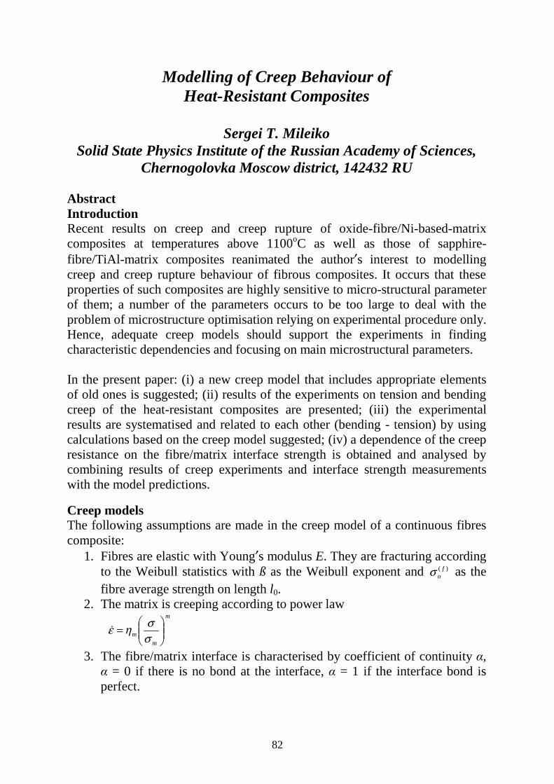
82
Modelling of Creep Behaviour of Heat-Resistant Composites
Sergei T. Mileiko
Solid State Physics Institute of the Russian Academy of Sciences, Chernogolovka Moscow district, 142432 RU
Abstract Introduction Recent results on creep and creep rupture of oxide-fibre/Ni-based-matrix composites at temperatures above 1100oC as well as those of sapphire-fibre/TiAl-matrix composites reanimated the author′s interest to modelling creep and creep rupture behaviour of fibrous composites. It occurs that these properties of such composites are highly sensitive to micro-structural parameter of them; a number of the parameters occurs to be too large to deal with the problem of microstructure optimisation relying on experimental procedure only. Hence, adequate creep models should support the experiments in finding characteristic dependencies and focusing on main microstructural parameters. In the present paper: (i) a new creep model that includes appropriate elements of old ones is suggested; (ii) results of the experiments on tension and bending creep of the heat-resistant composites are presented; (iii) the experimental results are systematised and related to each other (bending - tension) by using calculations based on the creep model suggested; (iv) a dependence of the creep resistance on the fibre/matrix interface strength is obtained and analysed by combining results of creep experiments and interface strength measurements with the model predictions. Creep models The following assumptions are made in the creep model of a continuous fibres composite:
1. Fibres are elastic with Young′s modulus E. They are fracturing according to the Weibull statistics with ß as the Weibull exponent and )( f
oσ as the fibre average strength on length l0.
2. The matrix is creeping according to power law m
mm
=
σσηε�
3. The fibre/matrix interface is characterised by coefficient of continuity α, α = 0 if there is no bond at the interface, α = 1 if the interface bond is perfect.
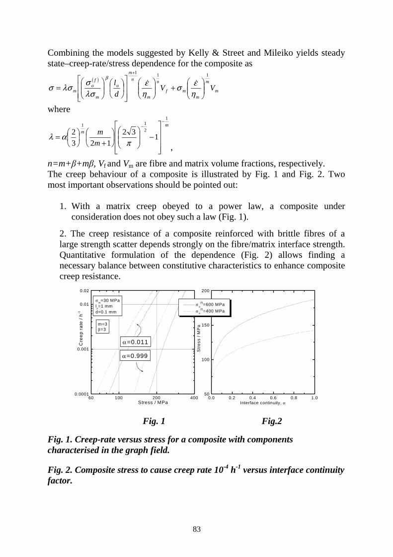
83
Combining the models suggested by Kelly & Street and Mileiko yields steady state–creep-rate/stress dependence for the composite as
( )
m
m
mmf
n
m
nm
o
m
fo
m VVdl
111
+
=
+
ηεσ
ηε
λσσλσσ
βDD
where m
m
mm
1
211
132123
2−
−
−
+
=π
αλ,
n=m+β+mβ, Vf and Vm are fibre and matrix volume fractions, respectively. The creep behaviour of a composite is illustrated by Fig. 1 and Fig. 2. Two most important observations should be pointed out:
1. With a matrix creep obeyed to a power law, a composite under consideration does not obey such a law (Fig. 1).
2. The creep resistance of a composite reinforced with brittle fibres of a large strength scatter depends strongly on the fibre/matrix interface strength. Quantitative formulation of the dependence (Fig. 2) allows finding a necessary balance between constitutive characteristics to enhance composite creep resistance.
0.0 0.2 0.4 0.6 0.8 1.050
100
150
200
60 100 200 4000.0001
0.001
0.01
0.02
Str
ess
/ MP
a
Interface continuity, α
σ o(f)=600 MPa
σ o(f)=400 MPa
α =0.999
α =0.011
σ m=30 MPalo=1 mmd=0.1 mm
m=3β=3
Cre
ep r
ate
/ h-1
Stress / MPa Fig. 1 Fig.2 Fig. 1. Creep-rate versus stress for a composite with components characterised in the graph field. Fig. 2. Composite stress to cause creep rate 10-4 h-1 versus interface continuity factor.
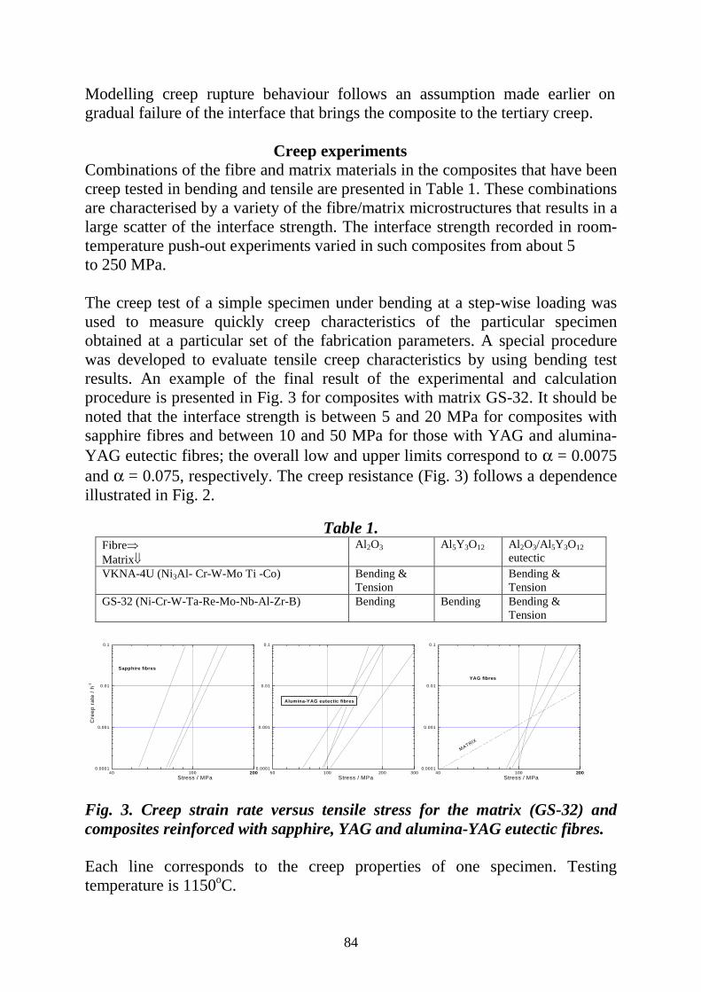
84
Modelling creep rupture behaviour follows an assumption made earlier on gradual failure of the interface that brings the composite to the tertiary creep.
Creep experiments Combinations of the fibre and matrix materials in the composites that have been creep tested in bending and tensile are presented in Table 1. These combinations are characterised by a variety of the fibre/matrix microstructures that results in a large scatter of the interface strength. The interface strength recorded in room-temperature push-out experiments varied in such composites from about 5 to 250 MPa. The creep test of a simple specimen under bending at a step-wise loading was used to measure quickly creep characteristics of the particular specimen obtained at a particular set of the fabrication parameters. A special procedure was developed to evaluate tensile creep characteristics by using bending test results. An example of the final result of the experimental and calculation procedure is presented in Fig. 3 for composites with matrix GS-32. It should be noted that the interface strength is between 5 and 20 MPa for composites with sapphire fibres and between 10 and 50 MPa for those with YAG and alumina-YAG eutectic fibres; the overall low and upper limits correspond to α = 0.0075 and α = 0.075, respectively. The creep resistance (Fig. 3) follows a dependence illustrated in Fig. 2.
Table 1. Fibre⇒ Matrix⇓
Al2O3 Al5Y3O12 Al2O3/Al5Y3O12 eutectic
VKNA-4U (Ni3Al- Cr-W-Mo Ti -Co) Bending & Tension
Bending & Tension
GS-32 (Ni-Cr-W-Ta-Re-Mo-Nb-Al-Zr-B) Bending Bending Bending & Tension
40 100 2002000.0001
0.001
0.01
0.1
50 100 200 3000.0001
0.001
0.01
0.1
40 100 2002000.0001
0.001
0.01
0.1
YAG fibres
MATRIX
Stress / MPa
Alumina-YAG eutectic fibres
Stress / MPa
Sapphire fibres
Cre
ep r
ate
/ h-1
Stress / MPa Fig. 3. Creep strain rate versus tensile stress for the matrix (GS-32) and composites reinforced with sapphire, YAG and alumina-YAG eutectic fibres. Each line corresponds to the creep properties of one specimen. Testing temperature is 1150oC.

85
Another example of the comparison of experimental and calculated creep properties of the composites is presented in In Fig. 4. In this case, the interface strength is lower than in the case of composites with GS-32 matrix (α is assumed to be equal 0.005). A set of reasonable parameters yields a fairly good agreement between experimental points and theoretical predictions.
0.0 0.1 0.2 0.3 0.4 0.50
50
100
150
200
250
Al2O3/VKNA-4U
m=5.4 η =10-4h-1
σ m=41 MPaσ o
(f)=200 MPa β=3lo=1 mm d=0.1 mm
ε=1 h-1
ε=3.10-3 h-1
ε=10-4-1.4.10-4 h-1
ε=1 h-1
ε=3.10-3 h-1
ε=10-4-1.4.10-4 h-1
Str
ess
/ MP
a
Fibre volume fraction
Fig. 4 Comparison of experimental and calculated creep properties
In Fig. 4 above the calculated (lines) and experimental (points) dependencies of stress to cause a certain creep rate on fibre volume fracture. Continuity parameter α = 0.005, the other parameters are shown in the graph field. Note that creep rate εD = 1 h-1 is obtained in a normal short-time testing. Conclusion A simple model of creep and creep rupture of metal matrix composites reinforced with brittle fibres is suggested. The model is shown to describe a real behaviour of the composite sufficiently well. It is clearly possible to use the model to optimise composite microstructure that is important since composite creep is affected by a large number of microstructural parameters.
86
Optimisation of Material Distribution for Prescribed Brittle Fracture Characteristics in
Functionally Graded Material Coatings
Hideki Sekine Department of Aeronautics and Space Engineering,
Tohoku University, Aoba-yama 01, Aoba-ku, Sendai 980-8579, Japan
Abstract Functionally graded material (FGM) coatings have been used in applications in various branches of modern technology. FGM coating/substrate systems may be considered as semi-infinite FGM media because the coatings are usually of very small thickness in comparison with the dimensions of the substrates. This paper is concerned with an optimisation of material distribution in the FGM coatings with a view to controlling the brittle fracture characteristics of the coatings. Simulating the non-homogeneity of FGM coating by on equivalent eigenstrain, we present an approximation method to calculate the stress intensity factor of an edge crack in the FGM coating. After the stress intensity factor has been calculated using the approximation method, the apparent fracture toughness is given by equating the stress intensity factor to the intrinsic fracture toughness of the FGMs. The optimisation problem of material distribution for prescribed apparent fracture toughness in the FGM coatings is set up and the numerical results for an Al2O3-TiC FGM coating/Al2O3 substrate system are shown.

87
Poisson's Ratio and Thermal Expansion: How to Use Both to Minimise Internal Strains in many Types of Composite
Anthony Kelly
Materials Science and Metallurgy, University of Cambridge Pembroke Street, Cambridge CB2 3QZ, UK
Abstract Two important problems concerning structural integrity, particularly when different materials are in contact, are
1) difference in Poisson's ratio and 2) difference in thermal expansion coefficient.
The deleterious effects produced by these two differentials are very well known but bear repetition. Longitudinal splitting, de-cohesion of fibre and matrix, and some aspects of compressive failure are examples of the former which will be briefly reviewed. Examples of the latter are numerous and effect importantly brittle systems and metal-ceramic, or metal-metal or ceramic-polymer composite interfaces. The means which we have of controlling Poisson's ratio by using composite principles will be shown together with novel means of controlling thermal expansion. Thermal expansion can be controlled in many cases by using the two effects.

88
Determination of Local Stress Concentrations in Cracked Cross-Ply and Off-Axis Composites
Costas Galiotis
ICE/HT- FORTH, Stadiou Street, Platani, P.O.Box 1414, Patras, GR-26500, Greece
Abstract Accumulation of damage in the form of multiple cracking is a distinctive feature of many types of structural composites. In particular, in composite laminates, the prediction of first ply failure, the subsequent accumulation of matrix cracks and consequent mechanical property changes have been the focus of much work over the past twenty years. Transparent cross-ply GFRP laminates have been used in a number of these studies since they show cracking behaviour which is generic for all types of fibre-reinforced plastics and have the added benefit that the damage is easy to observe. Experimental parameters which relate to the macroscopic consequences of matrix cracking and can be measured readily include crack accumulation with increasing stress (or strain) and the resulting laminate changes in stiffness, Poisson’s ratio, co-efficient of thermal expansion and residual strain. The theoretical analyses of matrix cracking phenomena which relate to these experimental measurements vary in sophistication: shear-lag analyses, more rigorous elasticity analysis, variational mechanics and finite element solutions are all available. Each of these approaches varies in the way in which the stress transfer between plies in the vicinity of a matrix crack is treated and it would be valuable, therefore, to have a technique which is able to probe directly local stresses in the laminate. Non-destructive stress or strain measurements in composites can be made by employing the technique of laser Raman spectroscopy. This technique is based on the stress (strain) sensitivity of most Raman vibrational modes of crystalline fibres and is a direct consequence of the change in the bond stiffness with bond extension or contraction. The superiority of the Raman sensor over other existing sensors is its ability to provide a spatial resolution of 1 µm in measurements of stress or strain. Although this technique has a universal applicability, certain amorphous fibres such as glass have a very weak Raman response and, therefore, cannot be readily used as intrinsic stress/ strain sensors. In order to overcome this problem, a small amount of aramid fibres which exhibit very strong Raman response can be placed at strategic positions within a glass fibre laminate to act as stress or strain Raman sensors. In addition, by
89
matching the refractive index of the polymer matrix to that of the reinforcing fibre (glass), transparent composites can be made, which allow the interrogation of the aramid fibre at any required depth.
In this work we are studying in detail the matrix cracking phenomenon in glass fibre composites by embedding single aramid stress sensors at the 0°/90° ply interfaces of cross-ply laminates. The aim is to monitor the stress/strains in the 0° ply as a result of matrix cracking in the 90° ply. More recently the same procedure has been pursued for the determination of the stress concentration in the 0° ply for specimens with various mid-ply orientations [0/θ]s that have been manufactured with pre-inserted inter-ply notches. The stable growth of cracks in this case has allowed the quantification of the stress concentration ahead of the crack front (a) at various distances from the sensor (prior to crack spanning) and (b) after the crack has spanned the sensor (0° ply) position. In addition to the stress concentration data this methodology can also yield (a) the exact position of the crack mid-point (b) the width of the crack (c) the residual strain and (b) the modulus reduction as a function of applied stress or strain. The results obtained by this technique will be compared with existing analytical models and useful conclusions will be drawn.
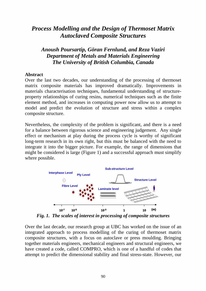
90
Process Modelling and the Design of Thermoset Matrix Autoclaved Composite Structures
Anoush Poursartip, Göran Fernlund, and Reza Vaziri
Department of Metals and Materials Engineering The University of British Columbia, Canada
Abstract Over the last two decades, our understanding of the processing of thermoset matrix composite materials has improved dramatically. Improvements in materials characterisation techniques, fundamental understanding of structure-property relationships of curing resins, numerical techniques such as the finite element method, and increases in computing power now allow us to attempt to model and predict the evolution of structure and stress within a complex composite structure. Nevertheless, the complexity of the problem is significant, and there is a need for a balance between rigorous science and engineering judgement. Any single effect or mechanism at play during the process cycle is worthy of significant long-term research in its own right, but this must be balanced with the need to integrate it into the bigger picture. For example, the range of dimensions that might be considered is large (Figure 1) and a successful approach must simplify where possible.
10110-310-510-7
Sub-structure Level
Ply Level
(m)
Interphase Level
Structure Level
Laminate levelFibre Level
10110-310-510-7
Sub-structure Level
Ply Level
(m)
Interphase Level
Structure Level
Laminate levelFibre Level
Fig. 1. The scales of interest in processing of composite structures
Over the last decade, our research group at UBC has worked on the issue of an integrated approach to process modelling of the curing of thermoset matrix composite structures, with a focus on autoclave or press moulding. Bringing together materials engineers, mechanical engineers and structural engineers, we have created a code, called COMPRO, which is one of a handful of codes that attempt to predict the dimensional stability and final stress-state. However, our

91
main goal has not been just COMPRO, but rather the creation of a framework or methodology for the use of process modelling in industry. From an industrial perspective, process modelling is, at least initially, a burden. The initial driver for the use of process modelling has been that even the most experienced people working on well-established parts have problems from time to time. In this context, we can differentiate between issues with part quality: porosity and voids, resin pooling, wrinkles, dimpling, and buckling being typical examples; and dimensional fidelity: warpage, spring-in, and thickness variations. Industry makes large complex structures, not small flat plates. Therefore, a modelling approach must include issues such as tooling interactions, component interactions (such as the bow wave created when a stiffener settles on a skin), variations in resin out-time, autoclave control features, variations from autoclave to autoclave, autoclave loading, temperature and pressure, debulking and bagging, and even bag leaks Currently, process modelling can help with dimensional fidelity problems in a very obvious way, by predicting the final shape. Part quality issues feed into a much bigger, even philosophical issue. The building block approach, which is the basis of much design, implicitly assumes that material in a small coupon is the same as material in a large structure, and that it is seeing the same residual stress. The reality is that currently we are performing structural analysis on the “as-designed” condition, whereas we should be using the “as-manufactured” condition. Thus, in the long term, analysis and understanding of a process will allow for increase dimensional control, improved part quality, reduced scrap, re-work, and repair, stabilised and optimised current processes, designed new processes, and tight integration into a structural design methodology. In a practical sense, this will lead to increased confidence in processes and design, elimination of experimental trials and prototype builds, determination of final local material ‘structure’, determination of internal stresses to evaluate structural performance, shortened development time, quicker design cycle, and decreased time to market, as well as better incoming material and process quality controls.
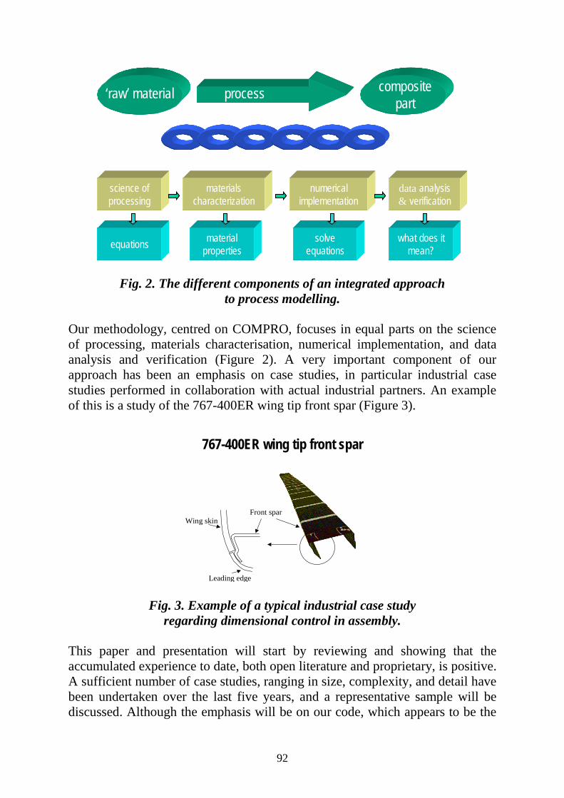
92
materialscharacterization
science of processing
numerical implementation
data analysis& verification
‘raw’ material process compositepart
equations materialproperties
solveequations
what does it mean?
materialscharacterization
science of processing
numerical implementation
data analysis& verification
‘raw’ material‘raw’ material processprocess compositepart
compositepart
equations materialproperties
solveequations
what does it mean?
Fig. 2. The different components of an integrated approach
to process modelling. Our methodology, centred on COMPRO, focuses in equal parts on the science of processing, materials characterisation, numerical implementation, and data analysis and verification (Figure 2). A very important component of our approach has been an emphasis on case studies, in particular industrial case studies performed in collaboration with actual industrial partners. An example of this is a study of the 767-400ER wing tip front spar (Figure 3).
767-400ER wing tip front spar
Leading edge
Front sparWing skin
Fig. 3. Example of a typical industrial case study regarding dimensional control in assembly.
This paper and presentation will start by reviewing and showing that the accumulated experience to date, both open literature and proprietary, is positive. A sufficient number of case studies, ranging in size, complexity, and detail have been undertaken over the last five years, and a representative sample will be discussed. Although the emphasis will be on our code, which appears to be the

93
most widely used on real structures, we will review other codes, and compare and contrast their capabilities and contributions. We will show that currently it is possible to get predictions of sufficient accuracy to be of use to industry. However, there are a number of issues that need to be considered. These range from the fundamental scientific to the applied engineering.
Mass Density
Specific Heat
Thermal Conductivity
Cure Rate
Thermophysical FlowResin Viscosity
Fibre Bed Permeability
Fibre Bed Stiffness
Cure Shrinkage
Thermal Expansion
Elastic Properties
MechanicalMass Density
Specific Heat
Thermal Conductivity
Cure Rate
Thermophysical FlowResin Viscosity
Fibre Bed Permeability
Fibre Bed Stiffness
Cure Shrinkage
Thermal Expansion
Elastic Properties
Mechanical
Table 1 Material properties that need to be characterised. Note that all these properties may be a function of degree of cure, temperature, and pressure. At one extreme, materials characterization is a significant issue. The number of parameters of interest are large (Table 1). All these properties are temperature dependant, degree of cure dependant, and perhaps even pressure dependant. Since the cost and effort of characterization is staggering, it is critical to use the simplest model possible for any given mechanism. Thus, for example, is it critical to model the full visco-elastic nature of the resin? In similar fashion, we can ask at the numerical implementation level whether it is necessary to have a full 3D model. At the other extreme, there are significant engineering problems: Some are practically mundane: for example, measurements are very difficult. Others are fundamental: a rigorous probabilistic approach appears necessary to deal with the unavoidable variability that exists in production. This in turn feeds into developing optimisation methodologies, which should take into account variability. The paper and presentation will end by highlighting those areas where more work is required, and where different approaches may be considered. This will hopefully lead to lively discussion and input, the net result of which will be guidance to those who are active in research in this important area. Acknowledgements: The authors would like to acknowledge the collaboration and funding from The Boeing Company (Phantom Works in Seattle and St. Louis, Commercial Airplane Group, Winnipeg), US Air Force Research Laboratory (WPAFB), Natural Sciences and Engineering Research Council of Canada (NSERC), Science Council of British Columbia, and Integrated Technologies (intec).

94
An Integrated Modelling Strategy for Processing and Properties of Textile Composites
Stepan V. Lomov, Eugene Belov and I. Verpoest
Department Metallurgy and Materials Engineering, Katholieke Universiteit Leuven, Belgium
Introduction Reliable prediction of processing characteristics and of the mechanical behaviour of composite materials is of primary importance for the success of their usage. This is certainly true for textile composites. The complexity of the structure and the presence of an outspoken hierarchy of structural and scale levels (10-5 m – fibres, 10-3 m – yarns/tows, 10-1 m – fabrics, 100 m – composite parts) lead to the a high degree of complexity in predictive models, a high level of approximation, and to the high level of uncertainty of the predictions, when errors are accumulated when the model progresses from one hierarchical level to another. However, the same hierarchy provides a very generic and reasonable route for construction of the predictive models, which is the subject of the paper. These predictive models should provide more confidence and help design engineers to use textile composites in many more applications. Hierarchy of the textile composite structure Table 1 shows the "staircase" of structural elements of a textile composite and of the modelling problems associated with each scale/structure level. The useful "rule of thumb" for the model is to avoid every unnecessary mixture of hierarchical levels: use yarn, not fibre, properties to predict behaviour of a fabric. Each level on the staircase is occupied by models, which use the input data of topology and spacing parameters of structural elements (i.e. weave pattern and warp/weft count) and properties of the elements themselves (i.e. yarns in a fabric) to predict properties of the structure (i.e. geometry of the fabric). If necessary, data from the lower level are introduced (i.e., fibrous structure of yarns in the fabric).
Level I. Fibre →→→→ Yarn: Fibrous structure of a yarn Normally considered circular, elliptical or lenticular, textile yarns and tows have a complex fibrous structure. Fine details of this structure can affect such properties of a composite as permeability and stress concentrations within yarns. The information of fibre distribution can be used for prediction of mechanical properties of yarns.
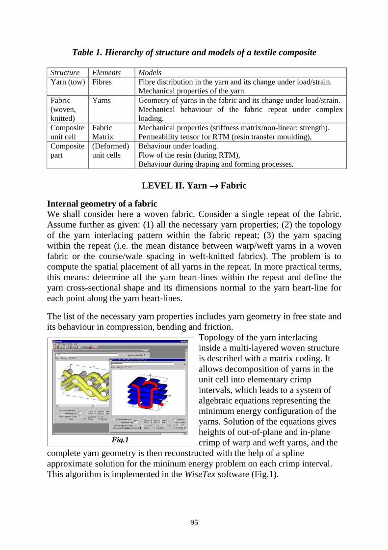
95
Table 1. Hierarchy of structure and models of a textile composite
Structure Elements Models Yarn (tow) Fibres Fibre distribution in the yarn and its change under load/strain.
Mechanical properties of the yarn Fabric (woven, knitted)
Yarns Geometry of yarns in the fabric and its change under load/strain. Mechanical behaviour of the fabric repeat under complex loading.
Composite unit cell
Fabric Matrix
Mechanical properties (stiffness matrix/non-linear; strength). Permeability tensor for RTM (resin transfer moulding),
Composite part
(Deformed) unit cells
Behaviour under loading. Flow of the resin (during RTM), Behaviour during draping and forming processes.
LEVEL II. Yarn →→→→ Fabric
Internal geometry of a fabric We shall consider here a woven fabric. Consider a single repeat of the fabric. Assume further as given: (1) all the necessary yarn properties; (2) the topology of the yarn interlacing pattern within the fabric repeat; (3) the yarn spacing within the repeat (i.e. the mean distance between warp/weft yarns in a woven fabric or the course/wale spacing in weft-knitted fabrics). The problem is to compute the spatial placement of all yarns in the repeat. In more practical terms, this means: determine all the yarn heart-lines within the repeat and define the yarn cross-sectional shape and its dimensions normal to the yarn heart-line for each point along the yarn heart-lines. The list of the necessary yarn properties includes yarn geometry in free state and its behaviour in compression, bending and friction.
Topology of the yarn interlacing inside a multi-layered woven structure is described with a matrix coding. It allows decomposition of yarns in the unit cell into elementary crimp intervals, which leads to a system of algebraic equations representing the minimum energy configuration of the yarns. Solution of the equations gives heights of out-of-plane and in-plane crimp of warp and weft yarns, and the
complete yarn geometry is then reconstructed with the help of a spline approximate solution for the mininum energy problem on each crimp interval. This algorithm is implemented in the WiseTex software (Fig.1).
Fig.1
96
Deformation of a dry fabric: compression Modelling of deformation of a dry fabric is the necessary part of any predictive model of a preform formability. When a woven fabric is compressed, the following changes in geometry take place: (1) warp and weft yarns are compressed; (2) the less crimped yarn system increases its crimp and vice versa. To compute the compression of yarns we use the known (measured) compression law of individual yarns and assume an even distribution of the compressive pressure over the fabric surface. The change of crimp is computed from the energy balance: work of compressive force on change of thickness = change of bending energy of yarns. The model, therefore, uses the same methodology as the model of internal geometry of yarns described above. Deformation of a dry fabric: tension, shear, bending The same approach can be applied for tension (bi- and uni-axial) of a woven fabric. Applied strain increases spacing of yarns in the fabric. Crimp heights in the deformed state are computed via the energy balance between work of transversal forces on change of crimp heights of warp and weft and change of bending energy of yarns. Strain of yarns in crimp intervals are then computed and forces evaluated using a non-linear tension diagram of the yarn. Similar approach can be applied to shear and bending of the fabric.
Level III. Fabric →→→→ unit cell of the composite Meso-mechanical model With the internal geometry, including the field of fibre volume fraction and direction, of the unit cell known, two types of meso-mechanical models can be used to compute the stiffness matrix of the unit cell. These models generate results with an error not greater then 20…30% against benchmark FEM calculations with the much lesser CPU time (minutes instead of days). A first series of models uses the actual yarn co-ordinates to derive the reinforcement volume fraction, orientation distribution, yarn shape and curvature (Yarn Path Mode). A typical example in this category is inclusion models. Analytical models which use a mapping of an actual textile fibrous structure on a regular 3D mesh rely on another type of idealisation in order to reduce the model complexity. The idealisation consists of a volume discretisation in which the original textile architecture is mapped into a 3D grid of simpler, homogenised elements (voxel partitioning). Examples are found both in finite element modelling (mosaic type models) and the cell models. Permeability models Fibre Distribution Mode – a point-by-point description of the porosity and fibre distribution inside the woven fabric, is used also as the input for the Lattice-Boltzmann permeability model. Preliminary results are very promising. For a glass woven fabric discussed above, the obtained experimental value for the

97
permeability coefficient in the weft direction was 9.4x10⁻¹⁰ m2, the model prediction was 8.0x10⁻¹⁰ m2.
Level IV: unit cell →→→→ composite part When properties of a unit cell of composite material are known, predictions on the uppermost hierarchical level become possible using general purpose or specialised FE packages. As shown on Fig.3, predictive models described above merge into an Integrated Design Tool, providing the long-waited solution for a designer of composite structures.
UNITCELL
TEXTILEYARN DATA TOPOLOGY SPACING
LOADING TEXTILE GEOMETRY MODEL
RELAXED GEOMETRY
DEFORMED GEOMETRY
MECH.BEHA-VIOUR
PERMEABILITY MODEL MESO-MECHANICAL MODELVISUALISATION
MECHANICAL BEHAVIOURPERMEABILITY TENSOR
FLOW MODELLING FORMING SIMULATION STRUCTURAL ANALYSISPART
Fig.2

98
Key issues for the Selection of Polymer-Matrix Composite Materials and Manufacturing Routes for
Performance and Cost Optimisation
Michael G. Bader School of Mechanical & Materials Engineering University of Surrey, Guildford, GU2 7XH, UK
ABSTRACT
Two distinct classes of composite materials have evolved over the past 60 years. There are commodity composites comprising E-glass reinforced unsaturated polyester resins and short-fibre reinforced thermoplastics, which account for more than 90% of the market, and the advanced composites based on carbon, aramid and other advanced fibres in higher performance matrices. They have been developed independently, the former serving the mass markets and the latter mainly sports, aerospace and military applications. There is a trend, now, for transfer of materials and technologies between these traditionally distinct sectors. This is due on, the one hand, to significant reductions of the cost of some high performance fibres and, on the other hand, a much greater emphasis on cost reduction in the aerospace and military sectors. The cost of a composite component or structure is determined by the costs of the feedstock and the manufacturing costs. The value of the part is determined by its performance, which may be measured in terms of the necessary mass to sustain the design loads, the service life and the cost of maintaining the part in service. The acquisition cost will be strongly influenced by the complexity of the part and by the required production rate. This will also influence the choice of manufacturing route. The factors influencing mechanical performance and structural efficiency are the choice of fibre and the ultimate fibre architecture. High fibre fraction and precise alignment are necessary to achieve the highest possible mechanical efficiency. These requirements unfortunately tend to increase the manufacturing cost and prejudice high volume production. The cost/performance potential of a number of different fibre/matrix combinations and alternative manufacturing routes is illustrated by an analysis based on the series production of a notional generic component. This shows that the lower cost advanced fibres, notably carbon, should have great potential in the commodity market and that alternative process routes open the way to greater cost/performance effectiveness in the advanced markets.

99

100