Report - D3
11
Deliverable D3.2 – WP 3 Due date: June 30, 2019 Title: Specification for a Tilt-meter Type: Report on the activity Dissemination level: Confidential, only for members of the consortium (including the Commission Services) WP Number: WP 3 Lead Beneficiary: UNINA Abstract As indicated in several papers [1,2] a suitable small number of tilt-meters can account for a complete recovery of Newtonian Noise and allows performing an efficient noise subtraction from the detector signal to obtain a better extraction of the Gravitational Wave signal from the noise. In order to obtain the main specifications on the tilt-meter as starting point, it is useful to constrain the level of sensitivity required to the tilt-meter. As already stated in the previous papers, the needed sensitivity is of the order of Hz rad n 12 10 ~ − ≤ ϑ in the region of frequencies spanning from about 4 to 20 Hz. To reach this extremely low level of sensitivity, it is required to overcome several experimental limits. The first one is the read-out sensitivity of the instrument. Standard optical levers systems [3] cannot reach such sensitivity and this forces to choose interferometric systems. Also, the tilt-meter must not couple the various degrees of freedom, in order to supply exactly the angular movement of the ground and not, let’s say, its horizontal or vertical accelerations.
Transcript of Report - D3

DeliverableD3.2–WP3
Duedate:June30,2019
Title: Specification for a Tilt-meter
Type:Report on the activity
Dissemination level: Confidential, only for members of the consortium (including the CommissionServices)
WPNumber:WP3
LeadBeneficiary:UNINA
Abstract
As indicated inseveralpapers [1,2]asuitablesmallnumberof tilt-meterscanaccount foracompleterecovery of NewtonianNoise and allows performing an efficient noise subtraction from the detectorsignaltoobtainabetterextractionoftheGravitationalWavesignalfromthenoise.Inordertoobtainthemainspecificationsonthetilt-meterasstartingpoint,itisusefultoconstrainthelevelofsensitivityrequiredtothetilt-meter.Asalreadystatedinthepreviouspapers,theneededsensitivityisoftheorder
ofHz
radn
1210~ −≤ϑ intheregionoffrequenciesspanningfromabout4to20Hz.
Toreachthisextremely low levelofsensitivity, it is requiredtoovercomeseveralexperimental limits.The first one is the read-out sensitivity of the instrument. Standard optical levers systems [3] cannotreachsuchsensitivityand this forces tochoose interferometric systems.Also, the tilt-metermustnotcouplethevariousdegreesoffreedom,inordertosupplyexactlytheangularmovementofthegroundandnot,let’ssay,itshorizontalorverticalaccelerations.
Finally,thesystemmustbedesignedinordertobemechanicallyrobustandcapableoftakingdataforatleastoneweekwithouthumanintervention.
Tofulfilltheseconstraintsandchecktheirneeds,aprototypetilt-meterhasbeendesignedandrealized.The test of this prototype has allowed to study themajor experimentally critical points and set thespecificationforthefinalinstruments.
MECHANICALDESIGN
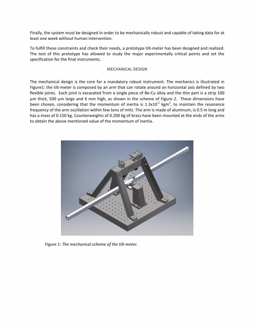
Themechanical design is the core for amandatory robust instrument. Themechanics is illustrated inFigure1:thetilt-meteriscomposedbyanarmthatcanrotatearoundanhorizontalaxisdefinedbytwoflexiblejoints.EachjointisexcavatedfromasinglepieceofBe-Cualloyandthethinpartisastrip100µmthick,500µmlargeand6mmhigh,asshown in theschemeofFigure2. Thesedimensionshavebeen chosen, considering that themomentum of inertia is 1.3x10⁻² kgm2, tomaintain the resonancefrequencyofthearmoscillationwithinfewtensofmHz.Thearmismadeofaluminum,is0.5mlongandhasamassof0.150kg.Counterweightsof0.200kgofbrasshavebeenmountedattheendsofthearmstoobtaintheabovementionedvalueofthemomentumofinertia.
Figure1:Themechanicalschemeofthetilt-meter.

Figure2:Thetechnicaldrawingofthejoints.
Thewholetilt-meterisrealizedinsteel,inordertomaintainrobustnessandhighresonancefrequenciesfor the modes not of interest. The major source of mechanical coupling is with the longitudinalaccelerationoftheground, i.e. theaccelerationalongthedirectionofthearm.As it iswellknown[4]thiscouplingcanbeminimizedbyhavingtherotationalaxisofthearmbeingcoincidentwiththecenterofmassofthearmitself.Indeedthegroundlongitudinalacceleration z!! producesthetorque δτ zm !!=wheremisthemassofthearmandδisthedistanceoftherotationaxisfromthecenterofmass.If,asitis in our case, the rotational resonance frequency is few tens ofmHz, the transfer function from the
applied torque τ to tiltθ for frequencies of the order or above fewHz is simply 22 ωδ
ωτ
ϑIzm
I!!
=−= ,
whereIisthemomentumofInertia.Thisequationsetsthefirstspecificationonthetilt-meter:theratiom/I is of the order of L-2,where L is the arm length, typically of the order of 0.5m; the longitudinalacceleration of ground depends greatly on the site. In sites located on the earth surface (notunderground) a typical value is shown in Figure 3, where in red we have reported the groundaccelerationattheVirgosite,whileothercolorsrefertoundergroundsites.

Figure3: left)Thepowerspectraldensityofaccelerationindifferentsitesoftheworld,withredcurvesindicatingthemaximumandminimumvalues.Right)ThevalueatdifferentEuropeansites,Virgobeingthe red curve, showinga valueof few10-11m2/s4/Hz for thepower spectral density, corresponding toabout6x10-6m/s2/Hz-1/2fortheusualsquareroot.
Consideringtheconservativevalueof z!! =6x10⁻⁶m/s2/Hz-1/2,tonotreintroduceanoiseinθhigherthanthespecification,theconstraintforthedistance δ isδ<25µm.Thisspecification impliesthatthetilt-metercenterofmassmustberegulatedpossiblywitharemotesystem.
OPTICALREAD-OUTANDCONTROLSYSTEM
Thefinalsensitivityrequiredtothetilt-metercannotbeachievedwiththeusualoptical leversystems.
Indeedeventhepresentlybestopticalleversreachfew10-11Hz
radwhichismorethanoneorderof
magnitudeworsethanspecifications[4,5].Aninterferometricsystemisthusrequired.Butconsideringthat in typical conditions thearmswill fluctuate around its equilibriumposition, due to seismicnoiseexcitations,particularlyattheresonancefrequency,acontrolsystemthatmaintainstheinterferometerontheworkingpointisrequiredaswell[6].
Asitiswellknown,sincetheinterferometricsignalisnotlinearforfluctuationsthatspanmorethanawavelength in the differential path of the interferometric arms, it is questionable if only aninterferometricread-outmaybesufficientorifitisbettertohaveanauxiliary,highrangesystem,tobeusedtobringthe interferometerto itsworkingpointandhenceswitchtheerrorsignalofthe loopontheinterferometer.
This strategy is used for example in several suspended apparatus, even in Virgo itself, and it is thestrategy that we have followed in designing and realizing a prototype to test and obtain thespecificationsforthefinaltilt-meter. Inourcasetheproposedsystemiscomposedbyanoptical leverthatconstitutestheauxiliarysystem.Thankstotheerrorsignalprovidedbytheopticallever,thesystemisbroughtaroundtheinterferometricworkingpoint.Hencetheloopisswitchedontheinterferometric

signalandtheopticalleverreadoutisnomoreused.TheactualschemeoftheprototypeopticalleversystemisreportedinFigure4.
Figure4:Theopticalleversystem.Abeam(inred)exitingfromanopticalfibercollimator(yellow)issentto a beam splitter. The light reflected by the beam splitter is sent towards the tilt-meter arm, impingperpendicularlytothearm.Onemirrorisfixedatthecenterofthearm.Itreflectsthebeambacktothebeamsplitterandthelighttransmittedbythebeamsplitterisreadbyamotorizedquadrantphotodiode(inorange).Atiltofthearmresultsinadisplacementofthebeamonthequadrant.
The optical lever configuration, particularly the perpendicularity to the arm, has been chosen tominimizethecouplingswithotherdegreesof freedom.Thearmof theoptical lever isabout6cm.Aspreviouslysaid,thissystemisauxiliarytotheinterferometricreadout.AschemeoftheinterferometerisreportedinFigure5.

Figure5:Theschemeof the interferometer.The interferometer isaMichelson interferometerwithun-equalarms.Theopticalcomponentsplacedintheupperpartofthefigureareallfixed.Theonlymovingpart of the interferometer is the tilt-meter arm. The light comes from the left side of the figure (redbeam)andimpingesinthecubicbeamsplitter.Thefirstpathisgivenbythelightreflectedbythebeamsplitter,whichissenttothefirstmirrorofthearmanditisreflectedbacktowardsthebeamsplitter.Thesecondpathisdeterminedbythelighttransmittedbythebeamsplitter.Itimpingesonamirrorplacedat45degreesandit issenttothesecondmirrorofthetilt-meterarm.Thebeamreflectedbythissecondmirrorcomesbacktothebeamsplitterwereitrecombineswiththebeamofthefirstpathtoexitfromthe output port. The read-out port (the vertical beam exiting the beam splitter) is read with a DCphotodiode.
Figure5also shows two lenses (inblack).These lenseshaveequal focal length to thedistance to thearm. Thismakes the interferometer contrast insensitive to the tilt of arm (at the first order), so thateven for arm rotations atmrad level, the interferometermaintains a goodperformance. This featuremakes the interferometer far more robust with respect to earthquakes, allowing long data takingwithoutintervention.
The control loop is closedwith the use of electrostatic actuators. These are simply 30 cm2 metallicplates,placedinfrontofthetilt-meterarm.Theyareparalleltothearm,inbothsidesandbothends.Theyareonlypartiallysuperimposedtothearm,sothatwhenavoltageisappliedtoacoupleofplatestheyexertaforce,andhenceatorque,tomaximizethefacingarea.
Apictureoftheactualtilt-meterisreportedinFigure6.

Figure6:Apictureofthetilt-meter.Thegreenlightistheinterferometerlight.
To test in laboratory the performances of the tilt-meter, it has been placed on a commercial seismicisolationplatform.TheresultsareshowninFigure7.Inthisworkingconditiontheloopisclosedontheinterferometricsignalandtheopticalleversignalisstillreadasanauxiliarychannel.
Figure 7: Sensitivity from low to high frequency. The optical lever is at its electronic noise. Theinterferometerisreadingtheresidualseismicnoise.
Figure7showsthesensitivityofthesystem.Atthepresentthesignalreadcorrespondstoseismicnoise.Indeedour lab isverynoisy,since it is located inan in-a-townacademicbuilding.Newmeasurementswillbeconductedinbetterenvironmentalconditions.Severaldaysofmeasurementhavebeentaken,totesttherobustnessofthesystem.
TheresultsarereportedinFigures8and9andcorrespondtotwoperiodsinwhichanearthquakehashappened.ThecaseofFigure8isanearthquakeinthenorthernofItaly,(epicenternearCasteldelRio(BO)29-12-2018–19:56)ofMagnitude2.7,atadistancefromourlabofabout700km.Oursystemhasbeen disturbed for few minutes and then the interferometer has recovered its working point.

Remarkably,asshownbythesignalA_y,whichistheopticalleversystem,thearmdoesnotrecoveritsinitialposition,because the interferometergets locked inadifferent fringe.Aspreviously stated, thisturnsouttobenotaproblemthankstotheopticalschemeoftheinterferometer,usingthetwolenseswithsuitablefocallength.
Figure8:Thesignalsduringafarandfeebleearthquake(Above,firstandsecondfromthe left:signalsandRMSof thesignalsent toactuators; thirdand fourth:control signalandRMSof the loop.Bottomline,firstandsecondplot:tiltasreadfromopticallever;thirdandfourth:theinterferometersignalanditsRMS).
Figure9showsthesameplotforanearerandstrongerearthquake.Inthiscasethemagnitudeis4.1andthe distance from the lab is about 300 km. Again the interferometer loses its working point for fewminutes, hence it gets locked again, in a different fringe. In this case all the signals aremuchmoredisturbedandinfacttheinterferometerfindsitsfinallockonapositionquitedifferentfromtheinitialone.Nonethelessthecontrastremainsverygoodanddatatakingcancontinue.

Figure9:Thesignalsincaseofanotfarandnotfeebleearthquake(themeaningofeachplotisthesameoffigure8).
OPERATIONONSITE
Thetilt-meterispresentlyoperatingattheVirgosite.Installationonsitehasshowntheneedofseveralspecificationsnotscientificbuttechnical,mainlyregardingnotgenerationofseismicorelectromagneticnoiseandspecificationsonintegrationofthesystemwiththewholeVirgodataacquisition.
Seismicnoisecanwellbeintroducedbythetilt-metervacuumpumps.Herethespecificationsaregiventhe seism at the site: the noise produced by the pumping system must be lower than the presentseismic noise as measured on the Virgo tower basement. Similar considerations apply for theelectromagneticnoise.
Specificationsonsystemintegrationregardmainlytheintegrationwiththedataacquisitionsystem.Thetilt-metersystemshouldnotbeseenasastand-alonesystem.Themainmotivationisthatastand-alonesystemcanhardlybeacquiredbytheVirgosystemandthusthesignalsbecomenotreal-time.Thisslowsdown the commissioning of the systems, the tests on noise generation and prevent from executingcoherence tests with the other sensors present in the building. The preparation of the system forintegration requires that both the control system (if any) and the data acquisition system will beperformeddirectlybytheVirgosystem.ThusthecontrolsystemmustbeaccessibletothegeneralVirgocontrol system at least for feed-back loop parameters settings. For the data acquisition, clearly ananalogread-outsignalshouldbeprovided.
The tilt-meter has been installed at the North-END building, alignedwith the Virgo North arm, sinceseveralweeks.Thetilt-meterhascontinuouslyacquireddatawithoutmajorproblemsbeing lockedontheinterferometersignal,asexpected.

Firstsignalshavebeenacquiredtotesttheintegration,thecontrolandtheacquisitionsystemsandalltheresultsarepositive.
Figure 10: Correction spectrum (above) and tilt spectra form optical lever (bottom orange curve) andinterferometer(bottombluecurve).Intheregionofinteresttheopticalleverisnearitssensitivitylimitofabout 5x10⁻¹⁰rad/sqrt(Hz)while the interferometer, as expected, is not limited by its sensitivity but isreadingatiltsignal.Thesesignalshavebeencomparedwithotherenvironmentalsignalsacquiredinthebuilding,particularlytheaccelerometers.
Figure11:Thetilt-metersignalshowscoherencewithaccelerometersignals.Thisistobeexpectedbothbecause theaccelerometers reada tiltηof thegroundasanaccelerationgxηand for thecouplingoftiltsandaccelerationsduetobuildingstructure.

CONCLUSIONS
Following all the above tests and considerations we can set the following specifications for the tilt-meter:
1)Sensitivityinrad/sqrt(Hz):10-12rad/sqrt(Hz)inthe]4:20[Hzmeasurementband;
2)Interferometricread-outsystemcombinedwithanauxiliaryhighrangecontrolsystem;
3)Mechanical robustness: it is recommended tonothavemovingopticalpartson the interferometerarmoronthereferencearm;
4)OpticalRobustness:itisrecommendedanopticalschemecapableofmaintainingtheinterferometercorrectlyworkingeveniflargestatic(orderofhundredsµrad)armtiltsarepresent;
5)ElectroniccompatibilitywithVirgocontrolandacquisitionsystem.
REFERENCES
[1]“Newtonian-noisecancellationinlarge-scaleinterferometricGWdetectorsusingseismictiltmeters”,JanHarms,KrishnaVenkateswara,Class.Quant.Grav.33(2016)no.23,234001.
[2] “Newtonian noise cancellation in tensor gravitational wave detector”, Ho Jung Paik, Jan Harms,JournalofPhysics:ConferenceSeries,Volume716(2016)no.1,012025.
[3] “An optical read-out system for the LISA gravitational reference sensor: present status andperspectives”,A.Grado,R.DeRosa,L.DiFiore,F.Garufi,L.Milano,G.Russano,V.Spagnuolo,JournalofPhysics:ConferenceSeries,Volune840(2017)no.1,012047.
[4]“Ahigh-precisionmechanicalabsolute-rotationsensor”,KrishnaVenkateswara,CharlesA.Hagedorn,MatthewD.Turner,TrevorArp,JensH.Gundlach,ReviewofScientificInstruments85,015005(2014).
[5] ”The Archimedes experiment”, E. Calloni et al., Nov 2, 2015. 2 pp. Nuclear Instruments andMethhodsA824(2016)646-647.
[6] “Improving sensitivity and duty-cicle of a double torsion pendulum”, M. Bassan et al.,Class.Quant.Grav.36(2019)no.12,12500.