
REPNET: project scheduling and workflow optimization for ...
12
CONSTRUCTION MANAGEMENT SPECIAL ISSUE #2/2013 ISSN 2036 1602 | http://in_bo.unibo.it Ricerche e progetti per il territorio, la città e l’architettura 17 Kalle Kahkonen Professor of Construction Management and Economics at Tampere University of Technology (www.tut.fi), he is co-ordinator of a global research society CIB working commission W65 “Organisation and Management of Construction” and an active member of IPMA. Presently his research interests cover new dimensions and novel tools of project management and project based business. REPNET: project scheduling and workflow optimization for Construction Projects REPNET: ottimizzazione della programmazione dei lavori per i progetti di costruzione Project planning and control are core processes for construction management. In practice project planning is achieved by network - based techniques like Precedence Diagramming Method (PDM). Indeed many researchers and practitioners claims that networking techniques as such do not provide a suitable model for construction projects. Construction process modeling should incorporate for specific features of resource flows through project activities. So an improved resource scheduling method for construction is developed, called REPNET, based on a precedence network plotted on a resource–space chart and presented with a flow-line chart. The heuristics of REPNET are used to carry out resource timing while optimizing processes flows and resource usage. The method has been tested on a sample project. La gestione della fase esecutiva del processo edilizio, Construction Management, ha come processo fondamentale la pianificazione ed il controllo. In pratica la programmazione dei lavori è spesso realizzata tramite tecniche reticolari come il PDM, tuttavia ricercatori ed operatori ritengono che le tecniche reticolari non siano del tutto adeguate per la costruzione, in quanto non sono focalizzate sull’impiego delle risorse ed il loro flusso nel progetto. Si propone quindi un metodo di programmazione che ottimizzi la schedulazione delle risorse, il REPNET, che è una procedura euristica basata su di un reticolo PDM organizzato in un piano risorse–spazio e presentato con la tecnica flow-line. Il REPNET procede alla programmazione delle risorse ottimizzandone sia l’impiego che il flusso del lavoro, come presentato con un semplice esempio. Keywords: construction management; project planning; activity network; resource scheduling; location based scheduling Parole chiave: construction management; processo edilizio; metodi reticolari; programmazione risorse; programmazione location-based Marco Alvise Bragadin Civil engineer (MSc), works as an assistant professor and researcher at the Department of Architecture (DA) of the University of Bologna (Bologna, Italy). His research work focuses on Construction Management and Building Production Technology. He is teacher of Building Site Organisation and Building Production at the School of Engineering and Architecture of the same university.
Transcript of REPNET: project scheduling and workflow optimization for ...
CONSTRUCTION MANAGEMENTSPECIAL ISSUE #2/2013
ISSN 2036 1602 | http:// in_bo.unibo.it
Ricerche e progett i per i l terr i tor io, la cit tà e l ’architettura
17
Kalle Kahkonen Professor of Construction Management and Economics at Tampere University of Technology (www.tut.fi), he is co-ordinator of a global research society CIB working commission W65 “Organisation and Management of Construction” and an active member of IPMA. Presently his research interests cover new dimensions and novel tools of project management and project based business.
REPNET: project scheduling and workflow optimization for Construction ProjectsREPNET: ottimizzazione della programmazione dei lavori per i progetti di costruzione
Project planning and control are core processes for construction management. In practice project planning is achieved by network - based techniques like Precedence Diagramming Method (PDM). Indeed many researchers and practitioners claims that networking techniques as such do not provide a suitable model for construction projects. Construction process modeling should incorporate for specific features of resource flows through project activities. So an improved resource scheduling method for construction is developed, called REPNET, based on a precedence network plotted on a resource–space chart and presented with a flow-line chart. The heuristics of REPNET are used to carry out resource timing while optimizing processes flows and resource usage. The method has been tested on a sample project.
La gestione della fase esecutiva del processo edilizio, Construction Management, ha come processo fondamentale la pianificazione ed il controllo. In pratica la programmazione dei lavori è spesso realizzata tramite tecniche reticolari come il PDM, tuttavia ricercatori ed operatori ritengono che le tecniche reticolari non siano del tutto adeguate per la costruzione, in quanto non sono focalizzate sull’impiego delle risorse ed il loro flusso nel progetto. Si propone quindi un metodo di programmazione che ottimizzi la schedulazione delle risorse, il REPNET, che è una procedura euristica basata su di un reticolo PDM organizzato in un piano risorse–spazio e presentato con la tecnica flow-line. Il REPNET procede alla programmazione delle risorse ottimizzandone sia l’impiego che il flusso del lavoro, come presentato con un semplice esempio.
Keywords: construction management; project planning; activity network; resource scheduling; location based schedulingParole chiave: construction management; processo edilizio; metodi reticolari; programmazione risorse; programmazione location-based
Marco Alvise BragadinCivil engineer (MSc), works as an assistant professor and researcher at the Department of Architecture (DA) of the University of Bologna (Bologna, Italy). His research work focuses on Construction Management and Building Production Technology. He is teacher of Building Site Organisation and Building Production at the School of Engineering and Architecture of the same university.
CONSTRUCTION MANAGEMENT | Bragadin KahkonenSPECIAL ISSUE #2/2013
ISSN 2036 1602 | http:// in_bo.unibo.it
Ricerche e progett i per i l terr i tor io, la cit tà e l ’architettura
18
INTRODUCTIONProject planning and control are core processes for Construction Project Management. In practice construction project scheduling is often accomplished with Activity Network. The most powerful networking technique now available for project planners is Precedence Diagramming Method (PDM) which can be easily implemented with a computer software. PDM is a Critical Path Method (CPM) networking technique, so it is a construction model in which a set of elements, called activities, are linked each other with logical relationships. This construction model represents building process by means of time flow between the network or the sequence of the activities that constitutes construction phases. But at the same time it represents another flow in the network, the workflow. Actually networking planning techniques are discrete and time oriented, instead construction process is a continue flow of operations (Tommelein, 1999). The success of network planning in term of use by construction planners is due to the fact that it is easily implemented by planning applications, and that its model is well suitable to the traditional conceptualization of construction (Koskela, 1992), ie workflow is not highlighted and the focus is on conversion activities. Despite its extensive use this method have a number of shortcomings (Adeli, 1999):
• network planning do not guarantee the work continuity requirement, which may result in crew being idle;• multiple crew strategies are difficult to implement in network planning, as resources are simply loaded on activities like features or labels;• network diagram is not suitable for monitoring the progress of the workflow in the project;• network methods do not provide an efficient structure for the representation of repetitive tasks, in fact all tasks are represented similarly and there is no consideration of the location of work in the scheduling process.
In fact construction projects are projects in which the physical dimensions of the building product are such to need to divide the project in smaller locations, called space units, as to better organize the work of various resources, construction crews, moving from one unit to another, i.e. performing repetitive activities in different locations. For example a concrete crew in a multi-storey building needs to move from one floor to another, or from one unit to another one to perform concrete work in the project.It is easy to note that this is the real essence of most large and complex construction projects. Kenley and Seppanen (2010) observed that the need of organizing the construction process performed by resources in different location needs the implementation of a “Location-Based Management System”.
RESEARCH METHODOLOGY AND LITERATURE REVIEWThe objective of the research is to define an heuristic procedure to help inexperienced construction project planners in the resource – constrained scheduling process. Two main tasks are tackled in the present research: the planning and scheduling procedure must be such as to permit inclusion of work-continuity requirement; and the project duration found must be minimized in order to minimize project cost, overhead cost in particular.Construction project are location – based projects (Kelley, Seppanen, 2010), where resources perform the same activity in different locations consecutively. So resource flow tracking is a main issue in construction planning and control. Resource – flow tracking is achieved by plotting the project PDM network on a resource space chart and showing the flow – line view of the project. As crews perform activities from a space unit of the project to another one, it might be advantageous to arrange for such crews to work continuously, without interruptions, thereby preventing idle intervals of equipment and manpower (Selinger, 1980). In fact scheduling process performed with networking techniques often prevent to satisfy the work continuity requirement because of the time relationship between activities is of the kind: “greater-than or equal-to”, and the search of the minimum total project duration performed by the algorithm often prevent the finish of one activity to coincide with the start of the successor activity on the same resource path, with the introduction of an interruption of the work flow. Because of it is believed that minimum total project duration search is of capital importance in construction projects, the work continuity constraint is relaxed in the constant resource allocation phase. Indeed a further optimization is implemented to achieve these two goals with resource loading modification.
CONSTRUCTION MANAGEMENT | Bragadin KahkonenSPECIAL ISSUE #2/2013
ISSN 2036 1602 | http:// in_bo.unibo.it
Ricerche e progett i per i l terr i tor io, la cit tà e l ’architettura
19
Many scheduling methods have been proposed in literature in order to improve construction project efficiency. El-Rayes and Mosehli (1998) suggested that resource – driven scheduling accounts directly for crew work continuity and facilitate effective resource utilization. They suggested that resource – driven scheduling of repetitive activities requires the satisfaction of three constraints: precedence relationship, crew availability and crew work continuity. Harris and Ioannou (1998) created the scheduling repetitive model that ensures continuous resource utilization with a flow view and a PDM view of the model. Arditi, Tokdemir and Suh (2001, 2002) integrated non – linear and discrete activities into LOB calculations and defined time and space interdependencies among activities as a base concept for repetitive project scheduling.Kang et alii (2001) observed that in a multiple repetitive construction project construction cost and duration are dependent on: number of work areas, proper crew grouping, size of work areas, frequency of repetition of each activity, and provided an heuristic approach to allow optimal construction planning. Yang and Ioannou (2001) proposed a scheduling method with focus on practical concerns in repetitive projects, in particular implemented the pulling effect in the continuity relationship between activities.Kenley and Seppänen (2009, 2010) observed that locations are important in construction because building can be seen as a discrete repetitive construction process, a series of physical locations in which work of variable type and quantity must be completed. They also observed that the location based methodology does not exclude Critical Path Method (CPM), in fact dependencies between activities in the various locations and between tasks that are made up of activities of the same work item are realized with CPM logic links. In summary, construction site space is an important concept and viewpoint for understanding characteristics of repetitive construction projects. The earlier research has covered already several important methodological characteristics of construction planning and scheduling with the site space on focus. Although not covered explicitly here some research has covered also computerized assistance for the generation of alternative plans and schedules – for example (Kahkonen, 1994; Märki et al, 2007). The research to be presented in the following chapters is also targeting to produce such a solution that would incorporate characteristics of repetitive construction operations and to present this together with computerized assistant that would enable efficient high quality scheduling.
REPETITIVE NETWORKING TECHNIQUE (REPNET): BASIC PRINCIPLESWith the aim of improving resource scheduling in construction projects with Precedence Diagramming Method, an heuristic algorithm for construction scheduling with repetitive activities in different project locations called REPNET is developed, based on a precedence network plotted on a resource–space chart (Bragadin 2010, Bragadin, Kahkonen 2011). In construction projects it is important that repetitive activities are planned in such a way as to enable timely movement of crews from one unit to the next, avoiding crew idle time. This is known as the “work continuity constraint” and its application during project planning can provide an effective resource utilization strategy that can lead to: maximization of the benefits from the learning curve effect for each crew; minimization of idle time of each crew; minimization of the off-on movement of crews on a project once work as begun.
RESOURCE-FLOW TRACKING WITH A RESOURCE – SPACE CHARTA Precedence Diagram Network of the repetitive project is plotted on a resource – space chart, with the x-axis representing resources and the y – axis representing space units of the project. So the network node representing the activity is identified by two coordinates: the main resource performing the activity and the work space in which the activity is to be performed. The procedure of plotting the network on a resource – space coordinates has been used by many researchers in the past. In particular Yi, Lee and Choi (2002) presented an heuristic method for network construction and development for repetitive units project, with the aim of minimizing total project duration by reducing idle time of resources and spaces. Actually the heuristic changes the sequence with which crews complete the scope of work encompassed in each repetitive activity. About this procedure Moselhi and Hassanein (2004) observed that this approach and general formulation has been applied in earlier and more accurate models (e.g. El Rayes and Moselhi, 1998) and that the Yi, Lee and Choi method does not guarantee a global optimum solution.
CONSTRUCTION MANAGEMENT | Bragadin KahkonenSPECIAL ISSUE #2/2013
ISSN 2036 1602 | http:// in_bo.unibo.it
Ricerche e progett i per i l terr i tor io, la cit tà e l ’architettura
20
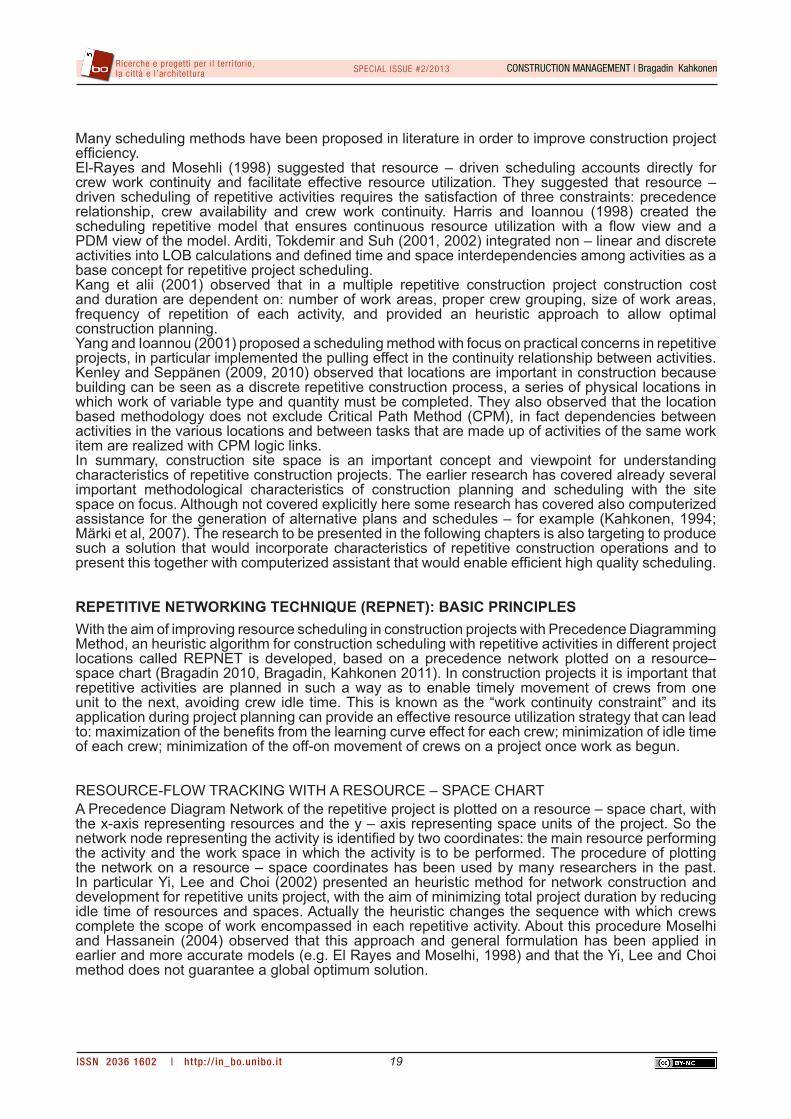
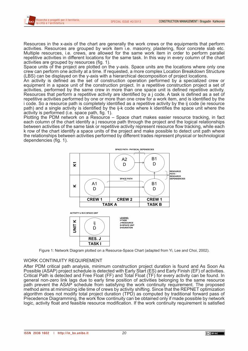
Resources in the x-axis of the chart are generally the work crews or the equipments that perform activities. Resources are grouped by work item i.e. masonry, plastering, floor concrete slab etc. Multiple resources, i.e. crews, are allowed for the same work item in order to perform parallel repetitive activities in different locations for the same task. In this way in every column of the chart activities are grouped by resources (fig. 1). Space units of the project are plotted on the y-axis. Space units are the locations where only one crew can perform one activity at a time. If requested, a more complex Location Breakdown Structure (LBS) can be displayed on the y-axis with a hierarchical decomposition of project locations. An activity is defined as the set of construction operation performed by a specialized crew or equipment in a space unit of the construction project. In a repetitive construction project a set of activities, performed by the same crew in more than one space unit is defined repetitive activity. Resources that perform a repetitive activity are identified by a j code. A task is defined as a set of repetitive activities performed by one or more than one crew for a work item, and is identified by the i code. So a resource path is completely identified as a repetitive activity by the ij code (ie resource path) and a single activity is identified by the ij-k code where k identifies the space unit where the activity is performed (i.e. space path, fig. 1). Plotting the PDM network on a Resource – Space chart makes easier resource tracking, in fact each column of the chart identify a j resource path through the project and the logical relationships between activities of the same task or repetitive activity represent resource flow tracking, while each k row of the chart identify a space units of the project and make possible to detect unit path where the relationships between activities performed by different trades represent physical or technological dependencies (fig. 1).
WORK CONTINUITY REQUIREMENTAfter PDM critical path analysis, minimum construction project duration is found and As Soon As Possible (ASAP) project schedule is detected with Early Start (ES) and Early Finish (EF) of activities. Critical Path is detected and Free Float (FF) and Total Float (TF) for every activity can be found. In general non-zero link lags due to early time position of activities belonging to the same resource path prevent the ASAP schedule from satisfying the work continuity requirement. The proposed method aims at minimizing idle time of crews by activity shifting. Since that the REPNET optimization algorithm does not modify total project duration (TPD) as computed by traditional forward pass of Precedence Diagramming, the work flow continuity can be obtained only if made possible by network logic, activity float and feasible resource modification. If the work continuity requirement is satisfied
RESOURCEPATH - RESOURCE
SPACE PATH DEPENDENCIES
ACTIVITY IJ IN K SPACE UNIT
LEGEND:I=TASKJ=RESOURCEK=SPACE UNITD=DURATION
UN
IT K
RES. JTASK I
TASK BTASK A
SPACE PATH - PHYSICAL DEPENDECIES
K1
CREW 1 CREW 2 CREW 1
K
A2D
A1D
B1D
B1D
ijD
Figure 1: Network Diagram plotted on a Resource-Space Chart (adapted from Yi, Lee and Choi, 2002).
CONSTRUCTION MANAGEMENT | Bragadin KahkonenSPECIAL ISSUE #2/2013
ISSN 2036 1602 | http:// in_bo.unibo.it
Ricerche e progett i per i l terr i tor io, la cit tà e l ’architettura
21
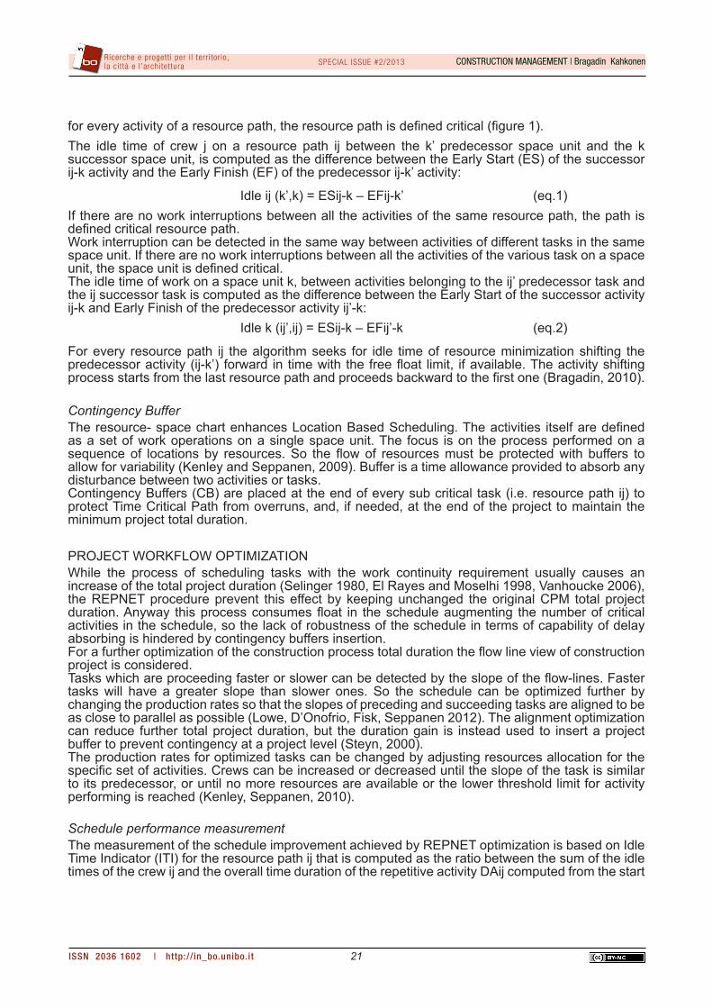
for every activity of a resource path, the resource path is defined critical (figure 1). The idle time of crew j on a resource path ij between the k’ predecessor space unit and the k successor space unit, is computed as the difference between the Early Start (ES) of the successor ij-k activity and the Early Finish (EF) of the predecessor ij-k’ activity:
Idle ij (k’,k) = ESij-k – EFij-k’ (eq.1)If there are no work interruptions between all the activities of the same resource path, the path is defined critical resource path.Work interruption can be detected in the same way between activities of different tasks in the same space unit. If there are no work interruptions between all the activities of the various task on a space unit, the space unit is defined critical.The idle time of work on a space unit k, between activities belonging to the ij’ predecessor task and the ij successor task is computed as the difference between the Early Start of the successor activity ij-k and Early Finish of the predecessor activity ij’-k: Idle k (ij’,ij) = ESij-k – EFij’-k (eq.2)
For every resource path ij the algorithm seeks for idle time of resource minimization shifting the predecessor activity (ij-k’) forward in time with the free float limit, if available. The activity shifting process starts from the last resource path and proceeds backward to the first one (Bragadin, 2010).
Contingency BufferThe resource- space chart enhances Location Based Scheduling. The activities itself are defined as a set of work operations on a single space unit. The focus is on the process performed on a sequence of locations by resources. So the flow of resources must be protected with buffers to allow for variability (Kenley and Seppanen, 2009). Buffer is a time allowance provided to absorb any disturbance between two activities or tasks.Contingency Buffers (CB) are placed at the end of every sub critical task (i.e. resource path ij) to protect Time Critical Path from overruns, and, if needed, at the end of the project to maintain the minimum project total duration.
PROJECT WORKFLOW OPTIMIZATIONWhile the process of scheduling tasks with the work continuity requirement usually causes an increase of the total project duration (Selinger 1980, El Rayes and Moselhi 1998, Vanhoucke 2006), the REPNET procedure prevent this effect by keeping unchanged the original CPM total project duration. Anyway this process consumes float in the schedule augmenting the number of critical activities in the schedule, so the lack of robustness of the schedule in terms of capability of delay absorbing is hindered by contingency buffers insertion.For a further optimization of the construction process total duration the flow line view of construction project is considered. Tasks which are proceeding faster or slower can be detected by the slope of the flow-lines. Faster tasks will have a greater slope than slower ones. So the schedule can be optimized further by changing the production rates so that the slopes of preceding and succeeding tasks are aligned to be as close to parallel as possible (Lowe, D’Onofrio, Fisk, Seppanen 2012). The alignment optimization can reduce further total project duration, but the duration gain is instead used to insert a project buffer to prevent contingency at a project level (Steyn, 2000).The production rates for optimized tasks can be changed by adjusting resources allocation for the specific set of activities. Crews can be increased or decreased until the slope of the task is similar to its predecessor, or until no more resources are available or the lower threshold limit for activity performing is reached (Kenley, Seppanen, 2010).
Schedule performance measurementThe measurement of the schedule improvement achieved by REPNET optimization is based on Idle Time Indicator (ITI) for the resource path ij that is computed as the ratio between the sum of the idle times of the crew ij and the overall time duration of the repetitive activity DAij computed from the start
CONSTRUCTION MANAGEMENT | Bragadin KahkonenSPECIAL ISSUE #2/2013
ISSN 2036 1602 | http:// in_bo.unibo.it
Ricerche e progett i per i l terr i tor io, la cit tà e l ’architettura
22
time of the activity of the crew on the first repetitive unit and the finish time of the activity on the last unit of the resource path:
ITI ij = [Σ Idle ij (k1,kn)] / DAij (eq.3)
The Idle Time Indicator is computed for each resource path before and after the REPNET procedure to detect schedule efficiency.
REPETITIVE NETWORKING TECHNIQUE: SCHEDULING PROCESSThe heuristics of REPNET carry out resource timing in three phases: in the first phase traditional PDM as soon as possible project schedule is performed; in the second phase the REPNET algorithm search for resource scheduling optimization by minimization of resource idle time in repetitive activity performance keeping constant the resources of each crew. The work continuity requirement fulfillment is achieved by activity shifting within the free float limit. In the third phase the project workflow optimization is performed by flow-line alignment procedure trough a new resource allocation procedure. The work continuity constraint is relaxed in order to maintain the PDM minimum project duration. In this way, besides the classic time critical path, a resource critical path is detected. Space critical path can be highlighted if useful. Time buffers are inserted to prevent from delays due to contingency (Bragadin, 2010).
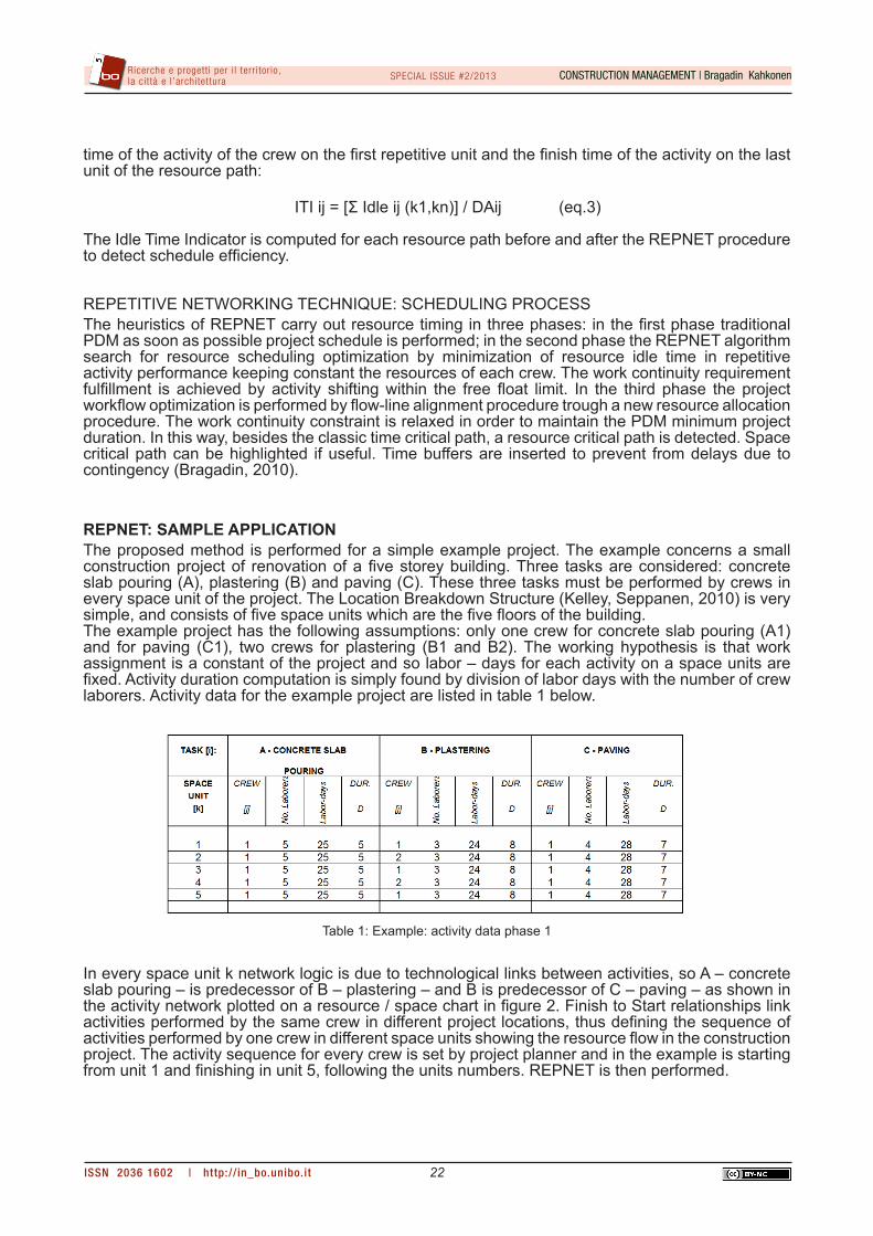
REPNET: SAMPLE APPLICATIONThe proposed method is performed for a simple example project. The example concerns a small construction project of renovation of a five storey building. Three tasks are considered: concrete slab pouring (A), plastering (B) and paving (C). These three tasks must be performed by crews in every space unit of the project. The Location Breakdown Structure (Kelley, Seppanen, 2010) is very simple, and consists of five space units which are the five floors of the building. The example project has the following assumptions: only one crew for concrete slab pouring (A1) and for paving (C1), two crews for plastering (B1 and B2). The working hypothesis is that work assignment is a constant of the project and so labor – days for each activity on a space units are fixed. Activity duration computation is simply found by division of labor days with the number of crew laborers. Activity data for the example project are listed in table 1 below.
In every space unit k network logic is due to technological links between activities, so A – concrete slab pouring – is predecessor of B – plastering – and B is predecessor of C – paving – as shown in the activity network plotted on a resource / space chart in figure 2. Finish to Start relationships link activities performed by the same crew in different project locations, thus defining the sequence of activities performed by one crew in different space units showing the resource flow in the construction project. The activity sequence for every crew is set by project planner and in the example is starting from unit 1 and finishing in unit 5, following the units numbers. REPNET is then performed.
Table 1: Example: activity data phase 1
CONSTRUCTION MANAGEMENT | Bragadin KahkonenSPECIAL ISSUE #2/2013
ISSN 2036 1602 | http:// in_bo.unibo.it
Ricerche e progett i per i l terr i tor io, la cit tà e l ’architettura
23
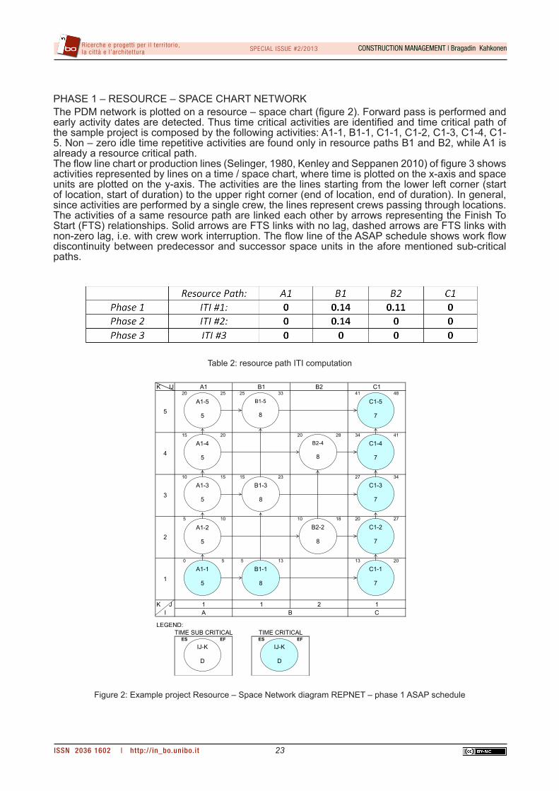
PHASE 1 – RESOURCE – SPACE CHART NETWORKThe PDM network is plotted on a resource – space chart (figure 2). Forward pass is performed and early activity dates are detected. Thus time critical activities are identified and time critical path of the sample project is composed by the following activities: A1-1, B1-1, C1-1, C1-2, C1-3, C1-4, C1-5. Non – zero idle time repetitive activities are found only in resource paths B1 and B2, while A1 is already a resource critical path.The flow line chart or production lines (Selinger, 1980, Kenley and Seppanen 2010) of figure 3 shows activities represented by lines on a time / space chart, where time is plotted on the x-axis and space units are plotted on the y-axis. The activities are the lines starting from the lower left corner (start of location, start of duration) to the upper right corner (end of location, end of duration). In general, since activities are performed by a single crew, the lines represent crews passing through locations. The activities of a same resource path are linked each other by arrows representing the Finish To Start (FTS) relationships. Solid arrows are FTS links with no lag, dashed arrows are FTS links with non-zero lag, i.e. with crew work interruption. The flow line of the ASAP schedule shows work flow discontinuity between predecessor and successor space units in the afore mentioned sub-critical paths.
Table 2: resource path ITI computation
K IJ20 25 25 33 41 48
15 20 20 28 34 41
10 15 15 23 27 34
5 10 10 18 20 27
0 5 5 13 13 20
K JI
LEGEND:
ES EF ES EF
A1 B1 B2 C1
1C
1 2
5
TIME SUB CRITICAL TIME CRITICAL
1A B
4
3
2
1
A1-3
5
A1-2
5
A1-1
5
B1-3
8
B2-2
8
B1-1
8
A1-4
5
B2-4
8
C1-3
7
C1-2
7
C1-1
7
C1-4
7
A1-5
5
B1-5
8
C1-5
7
IJ-K
D
IJ-K
D
Figure 2: Example project Resource – Space Network diagram REPNET – phase 1 ASAP schedule
CONSTRUCTION MANAGEMENT | Bragadin KahkonenSPECIAL ISSUE #2/2013
ISSN 2036 1602 | http:// in_bo.unibo.it
Ricerche e progett i per i l terr i tor io, la cit tà e l ’architettura
24
The Idle Time Indicator (ITI) for every resource path ij (eq. 3) is computed and showed in table 2 for phase 1.
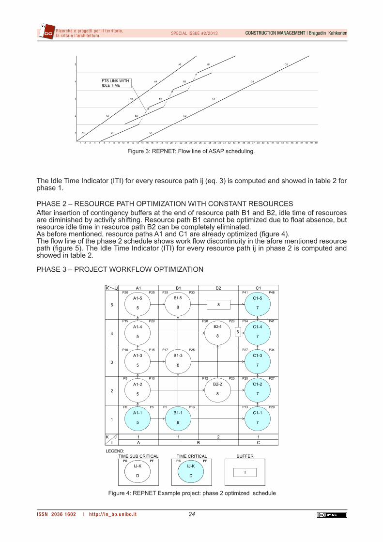
PHASE 2 – RESOURCE PATH OPTIMIZATION WITH CONSTANT RESOURCESAfter insertion of contingency buffers at the end of resource path B1 and B2, idle time of resources are diminished by activity shifting. Resource path B1 cannot be optimized due to float absence, but resource idle time in resource path B2 can be completely eliminated.As before mentioned, resource paths A1 and C1 are already optimized (figure 4).The flow line of the phase 2 schedule shows work flow discontinuity in the afore mentioned resource path (figure 5). The Idle Time Indicator (ITI) for every resource path ij in phase 2 is computed and showed in table 2.
PHASE 3 – PROJECT WORKFLOW OPTIMIZATION
5 A5 B1 C5
4 A4 B2 C4
3 A3 B1 C3
2 A2 B2 C2
1 A1 B1 C1
1 2 3 4 5 6 7 8 9 10 11 12 13 14 15 16 17 18 19 20 21 22 23 24 25 26 27 28 29 30 31 32 33 34 35 36 37 38 39 40 41 42 43 44 45 46 47 48 49 50
FTS LINK WITHIDLE TIME
Figure 3: REPNET: Flow line of ASAP scheduling.
K IJP20 P25 P25 P33 P41 P48
P15 P20 P20 P28 P34 P41
P10 P15 P17 P25 P27 P34
P5 P10 P12 P20 P20 P27
P0 P5 P5 P13 P13 P20
K JI
LEGEND:
PS PF PS PF
2
5
1A B
4
3
2
1
TIME SUB CRITICAL TIME CRITICAL
A1 B1 B2
BUFFER
C1
1C
1
A1-3
5
A1-2
5
A1-1
5
B1-3
8
B2-2
8
B1-1
8
A1-4
5
B2-4
8
C1-3
7
C1-2
7
C1-1
7
C1-4
7
A1-5
5
B1-5
8
C1-5
7
IJ-K
D
IJ-K
D
IJ-K
D
IJ-K
DT
8
6
Figure 4: REPNET Example project: phase 2 optimized schedule
CONSTRUCTION MANAGEMENT | Bragadin KahkonenSPECIAL ISSUE #2/2013
ISSN 2036 1602 | http:// in_bo.unibo.it
Ricerche e progett i per i l terr i tor io, la cit tà e l ’architettura
25
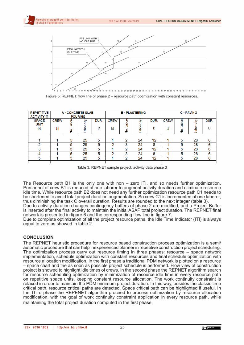
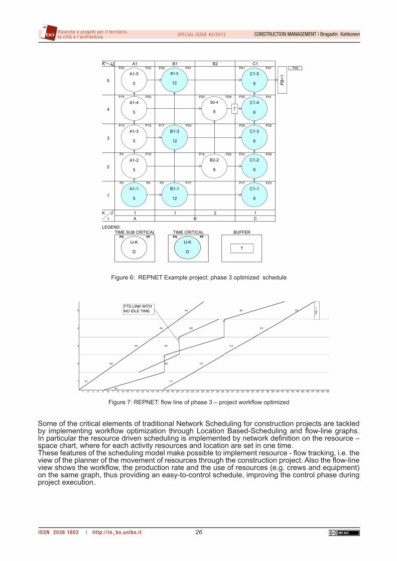
The Resource path B1 is the only one with non – zero ITI, and so needs further optimization. Personnel of crew B1 is reduced of one laborer to augment activity duration and eliminate resource idle time. While resource path B2 does not need any further optimization resource path C1 needs to be shortened to avoid total project duration augmentation. So crew C1 is incremented of one laborer, thus diminishing the task C overall duration. Results are rounded to the next integer (table 3). Due to activity duration changes contingency buffers of phase 2 are modified, and a Project Buffer is inserted after the final activity to maintain the initial ASAP total project duration. The REPNET final network is presented in figure 6 and the corresponding flow line in figure 7.Due to complete optimization of all the project resource paths, the Idle Time Indicator (ITI) is always equal to zero as showed in table 2.
CONCLUSIONThe REPNET heuristic procedure for resource based construction process optimization is a semi/automatic procedure that can help inexperienced planner in repetitive construction project scheduling. The optimization process carry out resource timing in three phases: resource – space network implementation, schedule optimization with constant resources and final schedule optimization with resource allocation modification. In the first phase a traditional PDM network is plotted on a resource – space chart and the as soon as possible project schedule is performed. Flow view of construction project is showed to highlight idle times of crews. In the second phase the REPNET algorithm search for resource scheduling optimization by minimization of resource idle time in every resource path on repetitive space units, keeping constant resource allocation. The work continuity constraint is relaxed in order to maintain the PDM minimum project duration. In this way, besides the classic time critical path, resource critical paths are detected. Space critical path can be highlighted if useful. In the Third phase the REPENET algorithm proceed to process optimization by resource allocation modification, with the goal of work continuity constraint application in every resource path, while maintaining the total project duration computed in the first phase.
5 A5 B1 C5
4 A4 B2 C4
3 A3 B1 C3
2 A2 B2 C2
1 A1
B1 C11 2 3 4 5 6 7 8 9 10 11 12 13 14 15 16 17 18 19 20 21 22 23 24 25 26 27 28 29 30 31 32 33 34 35 36 37 38 39 40 41 42 43 44 45 46 47 48 49 50
FTS LINK WITHIDLE TIME
FTS LINK WITHNO IDLE TIME
Figure 5: REPNET: flow line of phase 2 – resource path optimization with constant resources.
Table 3: REPNET sample project: activity data phase 3
CONSTRUCTION MANAGEMENT | Bragadin KahkonenSPECIAL ISSUE #2/2013
ISSN 2036 1602 | http:// in_bo.unibo.it
Ricerche e progett i per i l terr i tor io, la cit tà e l ’architettura
26
Some of the critical elements of traditional Network Scheduling for construction projects are tackled by implementing workflow optimization through Location Based-Scheduling and flow-line graphs. In particular the resource driven scheduling is implemented by network definition on the resource – space chart, where for each activity resources and location are set in one time. These features of the scheduling model make possible to implement resource - flow tracking, i.e. the view of the planner of the movement of resources through the construction project. Also the flow-line view shows the workflow, the production rate and the use of resources (e.g. crews and equipment) on the same graph, thus providing an easy-to-control schedule, improving the control phase during project execution.
K IJP20 P25 P29 P41 P41 P47 P48
P15 P20 P20 P28 P35 P41
P10 P15 P17 P29 P29 P35
P5 P10 P12 P20 P23 P29
P0 P5 P5 P17 P17 P23
K JI
LEGEND:
PS PF PS PFTIME SUB CRITICAL TIME CRITICAL
A1 B1 B2
BUFFER
C1
1C
1 2
5
1A B
4
3
2
1
A1-3
5
A1-2
5
A1-1
5
B1-3
12
B2-2
8
B1-1
12
A1-4
5
B2-4
8
C1-3
6
C1-2
6
C1-1
6
C1-4
6
A1-5
5
B1-5
12
C1-5
6
IJ-K
D
IJ-K
D
IJ-K
D
IJ-K
DT
PB
=1
7
Figure 6: REPNET Example project: phase 3 optimized schedule
5 A5 B1 C5
4 A4 B2 C4
3 A3 B1 C3
2 A2 B2 C2
1 A1
B1
C1
1 2 3 4 5 6 7 8 9 10 11 12 13 14 15 16 17 18 19 20 21 22 23 24 25 26 27 28 29 30 31 32 33 34 35 36 37 38 39 40 41 42 43 44 45 46 47 48 49 50
FTS LINK WITHNO IDLE TIME
PB =
1
Figure 7: REPNET: flow line of phase 3 – project workflow optimized
CONSTRUCTION MANAGEMENT | Bragadin KahkonenSPECIAL ISSUE #2/2013
ISSN 2036 1602 | http:// in_bo.unibo.it
Ricerche e progett i per i l terr i tor io, la cit tà e l ’architettura
27
BIBLIOGRAPHY
Arditi D., Tokdemir O. B., Suh K. (2001) Scheduling System for repetitive unit construction using line-of-balance technology. Engineering, Construction and Architectural Management 8(2), 90 – 103.Arditi D., Tokdemir O. B., Suh K. (2002) Challenges in Line-of-Balance Scheduling. Journal of Con-struction Engineering and Management, vol 128(6), 545-556.Bragadin M. A. (2008). La programmazione dei lavori con i metodi reticolari. Ed. Maggioli.Bragadin M. A. (2010). Heuristic Repetitive Activity Scheduling Process for Networking Techniques. Proceedings of the CIB 2010 World Building Congress, Salford Quays, U.K. 1-12.Bragadin M., Kähkönen, K (2011). Heuristic Solution for Resource Scheduling for Repetitive Con-struction Projects. Proceedings of the MISBE 2011 CIB Congress, Amsterdam, The Netherlands.El Rayes K., Moselhi O. (1998). Resource-driven scheduling of repetitive activities. Construction Management and Economics, 16, 433-446.Harris R. B., Ioannou P. G. (1998). Scheduling Projects with repeating activities. Journal of Construc-tion Engineering and Management, vol 124(4), 269-278.Kähkönen, K. (1994). Interactive Decision Support System for Building Construction Scheduling. Journal of Computing in Civil Engineering, 8(4), pp. 519-535Kang L.S., Park I.C. and Lee B. H. (2001). Optimal Schedule Planning for Multiple, Repetitive Con-struction Process. Journal of Construction Engineering and Management, 127(5), 382-390.Kenley R., Seppänen O. (2009). Location-Based Management for Construction Projects: part of a new Typology for Project Scheduling Methodologies. Proceedings of the 2009 Winter Simulation Conference, 2563-2570 Kenley R., Seppänen O. (2010). Location-Based Management for Construction. Spon Press, U.K. Koskela L. (1992). Application of New Production Philosophy to Construction. CIFE Technical Report #72, Stanford University, USA, September 1992
CONSTRUCTION MANAGEMENT | Bragadin KahkonenSPECIAL ISSUE #2/2013
ISSN 2036 1602 | http:// in_bo.unibo.it
Ricerche e progett i per i l terr i tor io, la cit tà e l ’architettura
28
Lowe, R. H., D’Onofrio, M. F., Fisk, D.M., Seppanen O. (2012). A Comparison of Location - Based Scheduling with the traditional Critical Path Method. 2012 Annual meeting of American College of Construction Lawyers.Märki, F., Fischer, M., Kunz; J. and Haymaker, J. (2007). Decision Making for Schedule Optimization. Stanford University, CIFE Technical Report #169. Moselhi O., Hassanein A. (2004). Discussion of Network Creation and development for Repetitive-Unit Projects. Journal of Construction Engineering and Management, 130(4), 613-614.Selinger S. (1980). Construction planning for linear projects. Journal of Construction Division Ameri-can Society Civil Engineers, 106(2), 195-205.Steyn H. (2000). An investigation into the fundamentals of critical chain project scheduling Interna-tional. Journal of Project Management, 19(2000), 363-369.Tommelein I. D., Riley D. R. Howell G.A. (1999). Parade Game: Impact of work flow variability on trade performance. Journal of Construction Engineering and Management, vol 125, n.5/1999Vanhoucke M. (2006). Work Continuity Constraints in Project Scheduling. Journal of Construction Engineering and Management, 132 (1), 14-25.Yang I. T., Ioannou P. G. (2001). Resource-driven scheduling for repetitive projects: a pull-system approach. Proceedings of the 9th International Group for Lean Construction Conference, Singapore, 6-8 August, 365-377.Yi K.J., Lee H. and Choi Y.K. (2002). Network Creation and development for Repetitive-Unit Projects. Journal of Construction Engineering and Management, 128(3), 257-264.