Replacement Guidelines Service Compressors - · PDF fileReplacement Guidelines Service...
26
Replacement Guidelines Service Compressors for 4&6 Cylinder S-Series and Discus (D4D, D4S, D6D, D6S)
Transcript of Replacement Guidelines Service Compressors - · PDF fileReplacement Guidelines Service...

Replacement GuidelinesService Compressorsfor 4&6 Cylinder S-Series and Discus (D4D, D4S, D6D, D6S)

D5.4.5/0813/E
1 Introduction ....................................................................................................... 1
2 Nomenclature .................................................................................................... 1
2.1 Discus and S-Series compressors ..................................................................................... 1
2.2 Service compressors ......................................................................................................... 1
3 Nameplate .......................................................................................................... 1
4 Ident numbers ................................................................................................... 2
5 Technical comparisons..................................................................................... 2
5.1 Performance – Cross reference tables .............................................................................. 2
5.1.1 Capacity – R404A refrigerant ................................................................................. 2
5.1.2 Capacity – R134a refrigerant ................................................................................. 3
5.1.3 Capacity – R407C refrigerant ................................................................................. 4
5.1.4 Capacity – R22 refrigerant ..................................................................................... 4
5.1.5 Electrical values (current) – R404A refrigerant ...................................................... 5
5.2 Qualified refrigerants and oils ............................................................................................ 5
6 Dimensions ........................................................................................................ 6
6.1 Dimensions of 4M*S compressors ..................................................................................... 6
6.2 Dimensions of 6M*S compressors ..................................................................................... 7
6.3 Shut off valve position ........................................................................................................ 7
6.4 Comparison of dimensions ................................................................................................ 8
7 Operating envelopes ......................................................................................... 9
8 Motor .................................................................................................................. 9
8.1 Motor current characteristics ............................................................................................. 9
8.2 Motor codes ..................................................................................................................... 10
8.3 Motor protection INT69TM ............................................................................................... 10
8.4 Wiring diagrams ............................................................................................................... 11
8.4.1 4M*S, 6M*S compressors – Part Winding Start AW* .......................................... 11
8.4.2 4M*S, 6M*S compressors – Star Delta EW* ........................................................ 12
9 Terminal box .................................................................................................... 13
9.1 Terminal box dimensions ................................................................................................. 13
9.1.1 Discus and S- Series terminal box ....................................................................... 13
9.1.2 Service compressor terminal box ......................................................................... 14
9.1.3 Terminal box internal parts ................................................................................... 14
9.1.4 Terminal plate ....................................................................................................... 15
9.1.5 Grounding at Service compressor Terminal plate ................................................ 15
10 Oil label sticker ................................................................................................ 15
11 Accessories ..................................................................................................... 16
11.1 Standard delivery Service compressors .......................................................................... 16
11.2 Shut off valves ................................................................................................................. 16
11.3 Mounting parts ................................................................................................................. 16

D5.4.5/0813/E
11.4 Crankcase heater ............................................................................................................. 16
11.5 Oil pressure control .......................................................................................................... 17
11.5.1 Oil pressure switch OPS2 / OPS1 ........................................................................ 17
11.5.2 Oil pressure switch – Alco FD113ZU (A22 – 057) ............................................... 18
11.6 Liquid Injection ................................................................................................................. 18
11.6.1 DTC (Discharge Temperature Control) ................................................................ 18
11.6.2 Demand Cooling ................................................................................................... 18
11.7 Capacity control ............................................................................................................... 19
11.8 Unloaded start .................................................................................................................. 19
11.9 Additional fan ................................................................................................................... 19
12 Spare parts ...................................................................................................... 20
12.1 Common spare parts ....................................................................................................... 20
12.2 Different spare parts ........................................................................................................ 20
13 Service compressor in parallel operation...................................................... 20
13.1 Service compressor in parallel operation with active oil management systems .............. 20
13.2 Service compressor in parallel operation with passive oil management systems ........... 20
13.3 Service compressor trio operation ................................................................................... 21
14 Replacement on a Twin................................................................................... 21
14.1 Twin description ............................................................................................................... 21
14.2 Replacement of compressor on a Twin ........................................................................... 21
14.2.1 Replacement on Discus or S-Series Twin manufactured from March 1991 ........ 21
14.2.2 Replacement on Discus or “R” Twin manufactured before March 1991 .............. 22

D5.4.5/0813/E 1
1 Introduction
Service compressors are especially offered to replace the Discus and S-Series compressors 4 and 6 cylinders, without installation modification. The positions of the suction and discharge are the same. Service compressors are different from the Stream compressors by dimensions (for 1:1 replacement), and do not have CoreSense™ technology.
Figure 1
NOTE: The shut off valves are not part of the standard delivery of Service compressors.
2 Nomenclature
2.1 Discus and S-Series compressors
2.2 Service compressors
3 Nameplate
The nameplate is similar to the other Copeland® brand products semi-hermetic compressor nameplates. The nameplate position for Service compressors is below the oil pump.

2 D5.4.5/0813/E
Figure 2
4 Ident numbers
Table 1 below indicates the ident numbers of Service compressors in the AWM/D motor version.
Service Compressors
Model Ident Model Ident
4MFS1-13X 5013549 6MLS1-27X 5014188
4MAS1-22X 5013469 6MHS1-35X 5013947
4MLS1-15X 5013787 6MMS1-30X 5014268
4MHS1-25X 5013629 6MIS1-40X 5014020
4MMS1-20X 5013867 6MTS1-35X 5014348
4MIS1-30X 5013709 6MJS1-45X 5014100
Table 1
Other motor versions are available: EWL, EWK, EWM/D, AWC, AWR, AWX, AWY.
Service compressors can also be delivered filled with mineral oil in motor versions AWM/D and EWK.
5 Technical comparisons
5.1 Performance – Cross reference tables
5.1.1 Capacity – R404A refrigerant
Table 2: Medium temperature
D4SA-200X 27.49 12.65 D4DA-200X 30.21 12.54 4MAS1-22X 32.73 13.72
D4SH250X 35.09 16.42 D4DH-250X 38.58 16.28 4MHS1-25X 38.45 16.24
D4SJ-300X 42.81 19.33
D6SA-300X 41.80 19.10
D6SH-350X 54.01 24.40 D6DH-350X 56.56 24.17 6MHS1-35X 55.59 23.65
D6SJ-400X 62.74 28.89 D6DJ-400X 68.07 29.56 6MIS1-40X 64.64 27.61
D6SK-500X 73.10 34.21 6MJS1-45X 72.4 31.24
Medium temperature: -10°C / 45°C / 20°C / 0K
Service Compressor
Capacity
kW
Capacity
kW
S-Series Discus
DescriptionCapacity
kW
Power Input
kWDescription
Power Input
kWDescription
18.02
Power Input
kW
D4DJ-300X 46.60 19.88 4MIS1-30X 42.77

D5.4.5/0813/E 3
Table 3: Low temperature R404A
5.1.2 Capacity – R134a refrigerant
Table 4: Medium temperature R134a
Table 5: High temperature R134a
D4SF-100X 8.85 6.76 D4DF-100X 9.67 6.77 4MFS1-13X 10.66 7.43
D4SL-150X 11.92 8.62 D4DL-150X 13.08 9.06 4MLS1-15X 13.32 9.02
D4ST-200X 14.44 10.17 D4DT-220X 16.24 11.20 4MMS1-20X 15.08 10.10
D6SF-200X 13.50 9.59 4MLS1-15X 13.32 9.02
D6SL-250X 17.59 12.72 D6DL-270X 19.03 13.54 6MLS1-27X 19.03 13.34
D6ST-320X 21.30 15.46 D6DT-320X 23.6 16.38 6MMS1-30X 22.73 15.69
D6SU-400X 26.59 18.68 6MTS1-35X 25.57 17.43
Low temperature: - 35°C / 40°C / 20°C / 0K
DiscusS-Series
Capacity
kW
Service Compressor
DescriptionPower Input
kW
Capacity
kW
Power Input
kWDescription
Capacity
kW
Power Input
kWDescription
D4SF-100X 16.30 7.16 D4DF-100X 17.25 6.96
D4SA-100X 17.05 6.88 D4DA-100X 17.65 6.83
D4SL-150X 21.30 9.05 D4DL-150X 22.80 9.12
D4SH-150X 19.70 8.47 D4DH-150X 20.80 8.64
D4ST-200X 25.70 10.85 D4DT-220X 27.80 11.10
D4SJ-200X 25.80 11.10 D4DJ-200X 26.40 10.95
D6SF-200X 25.10 10.60
D6SL-250X 32.00 13.75 D6DL-270X 33.30
D6SH-200X 30.80 13.60 D6DH-200X 33.40 13.50
D6ST-300X 38.20 16.60
D6ST-320X 38.30 16.55 D6DT-320X 40.40 16.40
D6SJ-300X 36.40 16.15 D6DJ-300X 39.50 16.65
D6SU-400X 46.10 19.95
D6SK-400X 42.10 18.65
Medium temperature: -10°C / 45°C / 20°C / 0K
15.30
6MLS1-27X 32.27 12.99
4MMS1-20X 25.24 9.92
6MTS1-35X
4MLS1-15X 8.97
43.07 17.3
6MMS1-30X 38.18
Power Input
kWCapacity
Power Input
kW
4MFS1-13X 18.91 7.60
Description
22.86
S-Series Discus Service Compressor
Description CapacityPower Input
kWDescription Capacity
D4DA-200X 31.60 9.21 4MAS1-22X 34.56 10.13
D4DH-250X 38.70 12.10 4MHS1-25X 39.93 12.10
D4DJ-300X 46.80 15.00 4MIS1-30X 43.67 13.22
D6DH-350X 57.00 18.05 6MHS1-35X 57.00 17.82
D6DJ-400X 67.70 22.20 6MIS1-40X 64.73 20.46
6MJS1-45X 72.60 23.00
High temperature: +5°C / 50°C / 10K / 0K
Discus Service Compressor
Description CapacityPower Input
kWDescription Capacity
Power Input
kW

4 D5.4.5/0813/E
5.1.3 Capacity – R407C refrigerant
Table 6: High temperature R407C
5.1.4 Capacity – R22 refrigerant
Table 7: Medium temperature R22
Table 8: Low temperature R22
NOTE: Since Service compressors can have different capacities, it is advised to check if the system components (condensers, expansion valve etc...) are compliant with the replacement compressor.
D4SA-200X 43.20 13.80 D4DA-200X 44.50 13.45 4MAS1-22X 47.80 15.40
D4SH250X 53.90 17.55 D4DH-250X 56.80 17.65 4MHS1-25X 56.25 17.85
D4SJ-300X 63.90 21.60
D6SA-300X 61.40 20.70
D6SH-350X 78.10 27.00 D6DH-350X 84.10 26.70 6MHS1-35X 80.64 25.93
D6SJ-400X 95.10 32.30 D6DJ-400X 97.40 32.60 6MIS1-40X 93.25 30.48
D6SK-500X 114.00 38.10 6MJS1-45X 106.04 34.46
High temperature: +5°C / 50°C / 10K / 0K
4MIS1-30X 62.71 19.78D4DJ-300X 63.60 22.60
Description CapacityPow er Input
kWDescription Capacity
Pow er Input
kWDescription Capacity
Pow er Input
kW
S-Series Discus Service Compressor
D4SA-200X 27.30 11.25 D4DA-2000 29.30 11.05 4MAS1-22X 32.30 12.15
D4SH250X 34.90 14.30 D4DH-250X 37.10 14.45 4MHS1-25X 37.40 14.55
D4SJ-300X 40.60 16.95
D6SA-300X 39.40 17.05
D6SH-350X 50.50 22.10 D6DH-350X 55.4 21.9 6MHS1-35X 54.41 21.49
D6SJ-400X 58.80 25.80 D6DJ-400X 64.4 26.4 6MIS1-40X 62.80 24.80
D6SK-500X 71.30 29.80 6MJS1-45X 68.50 28.10
Medium temperature: -10°C / 45°C / 20°C / 0K
D4DJ-300X 43.60 17.55 4MIS1-30X 40.30 16.20
S-Series Discus Service Compressor
DescriptionCapacity
kW
Power Input
kWDescription
Capacity
kW
Power Input
kWDescription
Capacity
kW
Power Input
kW
D4DF-100X 7.79 5.79 4MFS1-13X 8.59 6.38
D4SL-150X 9.68 7.82 D4DL-150X 11.55 8.44 4MLS1-15X 11.65 8.51
D4ST-200X 11.15 8.86 D4DT-220X 13.90 10.00 4MMS1-20X 12.80 9.25
D6SL-250X 13.65 11.80 D6DL-270X 14.95 11.80 6MLS1-27X 14.71 11.61
D6ST-320X 16.05 13.40 D6DT-320X 18.70 14.40 6MMS1-30X 17.70 13.67
D6SU-400X 21.20 16.90 6MTS1-35X 19.85 15.32
Low temperature: - 35°C / 40°C / 20°C / 0K
DescriptionCapacity
kW
Power Input
kWDescription
Capacity
kW
Power Input
kW
S-Series Discus Service Compressor
DescriptionCapacity
kW
Power Input
kW

D5.4.5/0813/E 5
5.1.5 Electrical values (current) – R404A refrigerant
Low temperature: - 35°C / 40°C / 20°C / 0K
Medium temperature: -10°C / 45°C / 20°C / 0K
Table 9: Electrical values
5.2 Qualified refrigerants and oils
Service compressors are designed for use with the same refrigerants as Discus and S-Series compressors: R404A, R507, R407C, R134a, R22.
Both generations of compressors are designed to work either with ester oil or mineral oil. The oil pump and oil circulation in Service compressors is similar as in Discus and S-Series compressors.
Qualified refrigerants R22 R404A, R507, R407C, R134a, R22
Copeland® brand products standard oils
Suniso 3 GS Emkarate RL 32 3MAF
Servicing oils
Shell 22-12
Suniso 3 GS
Fuchs Reniso KM 32
Capella WF 32
Emkarate RL 32 3MAF
Mobil EAL Arctic 22 CC
Table 10: Qualified refrigerants and oils
LT MT LT MT LT MT
D4SF-100X 12.31 21.59 27.1 105 D4DF-100X 12.62 21.19 26.8 105 4MFS1-13X 12.83 20.81 25.8 105
D4SA-200X 23.75 31.6 175 D4DA-200X 16.21 23.19 32.5 175 4MAS1-22X 16.45 22.42 30.3 175
D4SL-150X 17.15 28.80 35.6 156
D6SF-200X 19.29 32.42 38.4 175
D4SH250X 29.99 42.4 199 D4DH-250X 20.86 29.95 41.5 199 4MHS1-25X 21.18 29.08 39.2 199
D4ST-200X 20.13 34.24 42.4 175 D4DT-220X 21.41 33.95 42.8 175 4MMS1-20X 21.82 33.25 40.9 175
D4SJ-300X 33.71 48.3 221
D6SA-300X 33.27 49.5 221
D6SL-250X 25.10 43.32 56.5 199 D6DL-270X 26.28 42.14 53.70 199 6MLS1-27X 26.06 41.30 51.9 199
D6SH-350X 45.09 63.6 304 D6DH-350X 30.78 44.75 63.50 304 6MHS1-35X 31.36 44.01 60.5 304
D6ST-320X 31.06 51.74 62.9 255 D6DT-320X 32.11 50.22 62.20 255 6MMS1-30X 32.68 49.29 60.7 255
D6SJ-400X 51.14 75.3 304 D6DJ-400X 34.60 52.18 83.00 304 6MIS1-40X 30.71 44.89 57.6 304
D6SU-400X 37.70 62.27 78 304 6MTS1-35X 32.68 49.29 60.7 255
D6SK-500X 62.57 89.4 393 6MJS1-45X 35.32 50.95 70.5 304
27.59 33.9 156
D4DJ-300X 22.61 34.41 52.5 221 4MIS1-30X
Current A MOC
A
LRA
A
D4DL-150X 17.86 28.23 35.3 156 4MLS1-15X 18.23
LRA
ADescription
Current A MOC
A
LRA
ADescription
S-Series Discus Service Compressor
22.93 33.61 46.7 221
DescriptionCurrent A MOC
A

6 D5.4.5/0813/E
6 Dimensions
The following drawings show the position of the suction and discharge valves as well as the sight glass and the terminal box.
The footprint of Service compressors is the same as Discus, S-Series and compressors from most other manufacturers for easy replacement.
6.1 Dimensions of 4M*S compressors
4MAS, 4MHS, 4MIS
4MFS, 4MLS, 4MMS
Table 11: 4M*S compressor dimensions in mm
Note: The dimensions are given with shut off valves which are not part of the standard delivery.
4MAS 4MHS 4MMS 4MIS 4MFS 4MLS
A
B
C
D
E
F 658 718
G
H
I
J
K 166 198
L 360
M
N 633.5 602
686
449
503
305
358
67
74.5
166
118
381
212
376 360
282
179
670
357

D5.4.5/0813/E 7
6.2 Dimensions of 6M*S compressors
Table 12: 6M* compressor dimensions in mm
6.3 Shut off valve position
The position of the suction and discharge valves of Service compressors is the same as for S-Series and Discus compressors. There is no need for changing the piping configuration.
Service compressors 4MAS, 4MAFS, 4MLS
6MLS1 6MIS 6MMS 6MJS 6MTS 6MHS
A
B
C 276.6 266 256 276.6
D
E
F 738 757 738 757
G
H 73.2 73.2
I
J
K 217 236 217 236
L 376 376
M 445 447
N 719.5 738.5 719.5 739.1 672.6 738.5
552
234
794
273
327
118
381
427
496
305
358
66
123.7

8 D5.4.5/0813/E
Discus compressors D4DA, D4DF, D4DL
6.4 Comparison of dimensions
Table 13: Comparison of dimensions in mm
Description Length Width Height Description Length Width Height Description Length Width Height
D4SF-100X 680 485 495 D4DF-100X 680 535 495 4MFS1-13X 686 503 450
D4SA-200X 650 485 495 D4DA-200X 650 535 495 4MAS1-22X 658 503 450
D4SL-150X 680 490 495
D6SF-200X 740 540 490
D4SH250X 670 490 495 D4DH-250X 670 535 495 4MHS1-25X 670 503 450
D4ST-200X 700 490 495 D4DT-220X 700 535 495 4MMS1-20X 670 503 450
D4SJ-300X 690 515 495
D6SA-300X 740 540 490
D6SL-250X 740 540 490 D6DL-270X 740 580 490 6MLS1-27X 738 552 445
D6SH-350X 760 540 490 D6DH-350X 760 580 490 6MHS1-35X 757 552 447
D6ST-320X 740 540 545 D6DT-320X 740 580 535 6MMS1-30X 738 552 496
D6SJ-400X 760 565 545 D6DJ-400X 760 580 545 6MIS1-40X 757 552 496
D6SU-400X 740 540 545 6MTS1-35X 794 552 496
D6SK-500X 770 570 539 6MJS1-45X 794 552 496
503 450D4DJ-300X 690 535 495 4MIS1-30X 718
4MLS1-15X 686 503 450D4DL-150X 680 535 495
S-Series Discus Service Compressor

D5.4.5/0813/E 9
7 Operating envelopes
The operating envelopes for R404A are shown in the diagrams below:
Low / Medium temperature Medium / High temperature
4MFS1-13X, 4MLS1-15X, 4MMS1-20X, 4MAS1-22X, 4MHS1-25X, 4MIS1-30X, 6MLS1-27X, 6MMS1-30X, 6MTS1-35X 6MHS1-35X, 6MIS1-40X, 6MJS1-45X
Figure 3
NOTE: For application envelopes with other refrigerants, please refer to Copeland® brand products Selection Software on www.emersonclimate.eu.
8 Motor
8.1 Motor current characteristics
For correct sizing of electrical protection devices and wire diameters use the values shown in Table 14 below:
Low temperature: - 35°C / 40°C / 20°C / 0K Medium temperature: -10°C / 45°C / 20°C / 0K Table 14: Motor current characteristics
0
5
10
15
20
25
30
35
40
45
50
55
60
-55 -50 -45 -40 -35 -30 -25 -20 -15 -10 -5 0
Evaporating Temperature (oC)
Co
nd
en
sin
g T
em
pe
ratu
re (
oC
)
R404A
0
5
10
15
20
25
30
35
40
45
50
55
60
-50 -45 -40 -35 -30 -25 -20 -15 -10 -5 0 5 10 15
Evaporating Temperature (oC)
Co
nd
en
sin
g T
em
pe
ratu
re (
oC
)
R404A
0o C Suction Gas Return
25o C Suction Gas Return
20 K Suction Superheat0o C Suction Gas Return
25o C Suction Gas Return
LT MT LT MT LT MT
D4SF-100X 12.31 21.59 27.1 105 D4DF-100X 12.62 21.19 26.8 105 4MFS1-13X 12.83 20.81 25.8 105
D4SA-200X 23.75 31.6 175 D4DA-200X 16.21 23.19 32.5 175 4MAS1-22X 16.45 22.42 30.3 175
D4SL-150X 17.15 28.80 35.6 156
D6SF-200X 19.29 32.42 38.4 175
D4SH250X 29.99 42.4 199 D4DH-250X 20.86 29.95 41.5 199 4MHS1-25X 21.18 29.08 39.2 199
D4ST-200X 20.13 34.24 42.4 175 D4DT-220X 21.41 33.95 42.8 175 4MMS1-20X 21.82 33.25 40.9 175
D4SJ-300X 33.71 48.3 221
D6SA-300X 33.27 49.5 221
D6SL-250X 25.10 43.32 56.5 199 D6DL-270X 26.28 42.14 53.70 199 6MLS1-27X 26.06 41.30 51.9 199
D6SH-350X 45.09 63.6 304 D6DH-350X 30.78 44.75 63.50 304 6MHS1-35X 31.36 44.01 60.5 304
D6ST-320X 31.06 51.74 62.9 255 D6DT-320X 32.11 50.22 62.20 255 6MMS1-30X 32.68 49.29 60.7 255
D6SJ-400X 51.14 75.3 304 D6DJ-400X 34.60 52.18 83.00 304 6MIS1-40X 30.71 44.89 57.6 304
D6SU-400X 37.70 62.27 78 304 6MTS1-35X 32.68 49.29 60.7 255
D6SK-500X 62.57 89.4 393 6MJS1-45X 35.32 50.95 70.5 304
27.59 33.9 156
D4DJ-300X 22.61 34.41 52.5 221 4MIS1-30X
Current A MOC
A
LRA
A
D4DL-150X 17.86 28.23 35.3 156 4MLS1-15X 18.23
LRA
ADescription
Current A MOC
A
LRA
ADescription
S-Series Discus Service Compressor
22.93 33.61 46.7 221
DescriptionCurrent A MOC
A

10 D5.4.5/0813/E
NOTE: The MOC and LRA values for S-Series and Discus compressors are given for compressors built from 2006 onward. For older compressors, motor values might be different. Please check the values printed on the original compressor nameplate.
8.2 Motor codes
Service compressors use the same motor codes as S-Series and Discus compressors.
Star-delta motor (Y/∆) – Code E
Part-winding motor (YY/Y) – Code A
Table 15: Motor version explanation
8.3 Motor protection INT69TM
The motor in Service compressors uses a new generation INT69TM thermistor protection which has the same main features as the previous one.
The temperature-dependent resistance of the thermistor (also PTC-resistance) is used to sense the winding temperature. Two chains of 3 thermistors, each connected in series are embedded in the motor windings in such a manner that the temperature of the thermistors can follow with little inertia.
An electronic module is required which switches a control relay, depending on the thermistor resistance. The module INT69TM for two chains with a 5-min time delay is installed in the terminal box to which the thermistors are connected.
Figure 4
The maximum test voltage for thermistors is 3V.
The total resistance of the thermistor chains on a cold compressor should be ≤ 1800 Ω.
IMPORTANT Different source for power supply and contact 11-14! Module malfunction! Use same potential for power supply and the switch contact of the control loop (11-14).
NOTE: For more information please refer to Application Guideline D6.3.4 “Semi-hermetic Compressors”.
Motor
Code
Power
Supply
Nominal
Voltage
Start
Connection
DOL
Connection
AWM 380-420 V/3~/50Hz 400 YY/Y Y
EWL 220-240 V/3~/50Hz 230 Y/DELTA DELTA
EWL 380-420 V/3~/50Hz 400 Y
EWM 380-420 V/3~/50Hz 400 Y/DELTA DELTA
AWR 220-240 V/3~/50Hz 230 YY/Y Y
AWY 500-550 V/3~/50Hz 525 YY/Y Y
AWD 440-480 V/3~/60Hz 460 YY/Y Y
EWK 220-240 V/3~/60Hz 230 Y/DELTA DELTA
EWK 380-420 V/3~/60Hz 380 Y
EWD 440-480 V/3~/60Hz 460 Y/DELTA DELTA
AWC 208-230 V/3~/60Hz 230 YY/Y Y
AWX 380 V/3~/60Hz 280 YY/Y Y

D5.4.5/0813/E 11
8.4 Wiring diagrams
8.4.1 4M*S, 6M*S compressors – Part Winding Start AW*
Legend:
A1 ....... INT69TM motor protection K1 ........ Contactor M1 A2 ....... Oil pressure switch K4 ........ Contactor M1 for second part winding A5 ....... Terminal box compressor M21 ..... Fan motor/condenser CCH .... Crankcase heater R2 ........ Crankcase heater F6 ....... Fuse for control circuit Y21 ...... Solenoid valve capacity control 1 F7 ....... Fuse for control circuit Y22 ...... Solenoid valve capacity control 2 F8 ....... Fuse for control circuit Y3 ........ Solenoid valve unloaded start F10 ..... Thermal protection switch M21
Figure 5

12 D5.4.5/0813/E
8.4.2 4M*S, 6M*S compressors – Star Delta EW*
Legend:
A1 ....... INT69TM motor protection K1 ........ Contactor M1 A2 ....... Oil pressure switch K2 ........ Y - Contactor M1 A5 ....... Terminal box compressor K3 ........ Δ - Contactor M1 CCH .... Crankcase heater M21 ..... Fan motor/condenser F6 ....... Fuse for control circuit R2 ........ Crankcase heater F7 ....... Fuse for control circuit Y21 ...... Solenoid valve capacity control 1 F8 ....... Fuse for control circuit Y22 ...... Solenoid valve capacity control 2 F10 ..... Thermal protection switch M21 Y3 ........ Solenoid valve unloaded start
Figure 6

D5.4.5/0813/E 13
9 Terminal box
The terminal box rating is IP67.
The electrical characteristics of Discus and Service compressors are very close. Therefore, motor protections (fuses, contactors) will be the same for both compressor generations.
Figure 7
Only 2 studs are used for the PTC cable connectors. Connection is done without nuts, by means of “flag” connectors.
Figure 8
9.1 Terminal box dimensions
Table 16: Terminal box dimensions in mm
9.1.1 Discus and S- Series terminal box
Length Width Height Length Width Height
245 192 107 239 201 136
Discus / S-Series Service Compressor
14 D5.4.5/0813/E
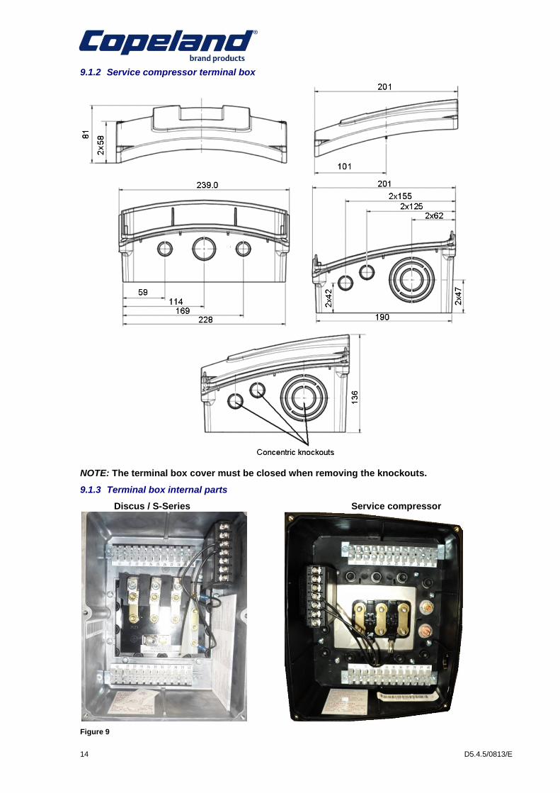
9.1.2 Service compressor terminal box
NOTE: The terminal box cover must be closed when removing the knockouts.
9.1.3 Terminal box internal parts
Discus / S-Series Service compressor
Figure 9

D5.4.5/0813/E 15
9.1.4 Terminal plate
Discus / S-Series Service compressor
Figure 10
9.1.5 Grounding at Service compressor Terminal plate
If grounding is needed, the grounding screw can replace one of the terminal plate bolts.
Remove one periphery bolt off the terminal plate and replace it with the grounding screw nut and washer like shown on the photos hereunder:
Figure 11
10 Oil label sticker
The oil level should be minimum at the bottom of the sight glass and maximum 1/4 of the sight glass. However, for operation with active oil management, mid-sight glass level is allowed.
Figure 12

16 D5.4.5/0813/E
11 Accessories
11.1 Standard delivery Service compressors
Blind flanges (instead of shut off valves)
With rubber spacers instead of mounting parts
INT69TM motor protection
OPS sensor fitted in the oil pump
Gasket pack for shut off valves
Filled with oil
With neutral gas charge
Black paint
11.2 Shut off valves
Service compressors are delivered without shut off valves and with blind flanges.
The shut off valves can be recovered from the replaced model and installed on the Service compressor.
The position of the shut off valves on the Service compressor is the same as on old compressors. Therefore there is no need to change the pipe configuration.
11.3 Mounting parts
Service compressors are delivered with rubber spacers.
Discus/S-Series spring mounting parts are compatible with Service compressors, as well as Stream ones.
Special mounting feet are delivered for compressor model 6MJS (corresponding to D6SK-500X).
11.4 Crankcase heater
Service compressors use the same crankcase heater element. The crankcase heater values are given in Table 17 below.
In compressors that are equipped with a deep oil sump, the heater element is inserted into a special chamber and fixed to the compressor body.
100 Watt heater element - If recovered from old compressor add heat sink paste.
200 Watt heater element
1. Magnetic plug 2. Securing piece 3. Heater element 200W 4. Deep oil sump

D5.4.5/0813/E 17
Table 17: Crankcase heaters
11.5 Oil pressure control
The oil pressure switch breaks the control circuit when the pressure difference between the oil pump outlet and the crankcase is too low. The switch must be properly adjusted and tamper-proof. If the oil differential pressure drops below the minimum acceptable value the compressor will be stopped after a 120 seconds delay. After having solved the problem the control has to be reset manually.
Proper oil pressure safety control with an approved switch is a condition of warranty!
Specifications for electro-mechanical oil pressure switches are as follows:
Cut-out pressure: 0.63 ± 0.14 bar
Cut-in pressure: 0.9 ± 0.1 bar
Time delay: 120 ± 15 sec.
NOTE: The oil pressure switches used in Discus or S-Series compressors are also compliant with Service compressors.
The following oil pressure switches can be delivered as accessories:
Electronic oil pressure switch OPS2
Mechanical oil pressure switch ALCO FD113 ZU
11.5.1 Oil pressure switch OPS2 / OPS1
The OPS sensor is delivered standard with Service compressor.
The OPS2 switch from Discus S-series can be used on Service compressor.
Wiring:
Brown (BN) = Power supply input
Violet (VIO) = Running signal from the compressor
Grey (GR) = Input changeover contact from the daisy chain
Orange (OG) = Output changeover contact linked to the compressor contactor
Pink (PK) = Output changeover contact linked to the alarm
Blue (BU) = Power supply output
S - Series CCH Discus CCH Service comp. CCH
D4SF-100X D4DF-100X 4MFS1-13X
D4SA-200X D4DA-200 4MAS1-22X
D4SL-150X D4DL-150X 4MLS1-15X
D4SH250X D4DH-250X 4MHS1-25X
D4ST-200X D4DT-220X 4MMS1-20X
D4SJ-300X D4DJ-300X 4MIS1-30X
D6SL-250X D6DL-270X 6MLS1-27X
D6SH-350X D6DH-350X 6MHS1-35X
D6SF-200X D6DT-320X 6MMS1-30X
D6SA-300X D6DJ-400X 6MIS1-40X
D6ST-320X 6MTS1-35X
D6SJ-400X 6MJS1-45X
D6SU-400X
D6SK-500X
100W
200W
100W
200W
100W
200W

18 D5.4.5/0813/E
Figure 13
NOTE: For more information on OPS2 please refer to Technical Information D7.8.3 “DWM Semi-hermetic Compressor - Oil Pressure Differential Switch OPS2” available on www.emersonclimate.eu.
11.5.2 Oil pressure switch – Alco FD113ZU (A22 – 057)
Specifications for electro-mechanical oil pressure switches are as follows:
Cut-out pressure: 0.63 ± 0.14 bar Cut-in pressure: 0.90 ± 0.1 bar Time delay: 120 ± 15 sec Protection class: IP30
Legend:
11 ......... Voltage connection
21 ......... Control voltage connection
22 ......... Control circuit
24 ......... Alarm connection
A2 ......... Oil pressure switch
A5 ......... Compressor terminal box
R ........... Relay
N ........... Neutral connection
t ............ Time delay
Figure 14
11.6 Liquid Injection
Liquid injection systems (DTC and Demand Cooling) were used for applications with R22 at low evaporating temperatures.
NOTE: R22 is no longer allowed for new refrigeration systems in Europe. Only recycled R22 is allowed for maintenance until 2015. From 1
st January 2015, R22 supply will be
forbidden.
Changing a compressor on an installation could be an opportunity to exchange R22 for a longer term refrigerant and at the same time to discard the liquid injection system.
11.6.1 DTC (Discharge Temperature Control)
The DTC liquid Injection used on S-Series cannot be used on Service compressors. The Demand Cooling system will be an alternative.
11.6.2 Demand Cooling
“Demand Cooling” as the term implies, means liquid refrigerant injection on demand.
Demand Cooling was required for R22 operation of Discus compressors at low temperature.
On 4-cylinder Service compressors, the nozzles, temperature sensor, Demand Cooling module and bracket, valve and coil from a D4D can be reused. The bracket and tubing should be changed.
The Demand Cooling kit cannot be recovered from 6-cylinder compressors; the Demand Cooling kit of a Stream compressor should be used instead.

D5.4.5/0813/E 19
11.7 Capacity control
Service compressors use the same principle for capacity control as S-Series and Discus compressors.
The capacity control kit (valve plate, cylinder head, control valve, gaskets, bolts) or control valve from a Discus or S-Series compressor cannot be recovered to install on a Service compressor.
Capacity control should be ordered as an accessory (already assembled together with the compressor) or as a separate upgrade kit.
11.8 Unloaded start
Service compressors use the same principle for unloaded start as S-Series and Discus compressors.
The unloaded start kit or control valve from a Discus or S-series compressor cannot be recovered to install on a Service compressor. The unloaded start should be ordered as an accessory (already assembled together with the compressor) or as a separate upgrade kit.
11.9 Additional fan
The fan can be recovered from the old compressor, but the mounting parts will have to be changed. The fan mounting kit has to be ordered separately.
Service compressor models do not have any studs for fan (studs are part of the fan mounting kit).
Description Ident
4M* 3011694
6M* 3011718
Stream Mounting Kit Fan

20 D5.4.5/0813/E
12 Spare parts
12.1 Common spare parts
Many parts are common to Service compressors and the Discus and S-series equivalent compressors:
- Shut off valves - Suction screen and gasket - Oil pump with OPS sensor - Oil sight glass - Oil screen, magnetic plug - Stator cover and gasket - Terminal plate - Relief valve - Oil and gas check valve - Bottom plate and gasket - Piston rings
12.2 Different spare parts
A few main parts are different and not interchangeable between Discus and S-series, and Service compressors:
- Valve plates and valve plate gaskets - Pistons and connecting rods - Cylinder heads - Stator cover gasket - Crankshaft
Spare parts for Discus, S-Series and Service compressors can be selected with the spare parts software at http://parts.emersonclimate.eu/IPP1/.
13 Service compressor in parallel operation
13.1 Service compressor in parallel operation with active oil management systems
The Service compressor sight glass design and position are the same as on previous models (D4S, D4D, D6S & D6D). Therefore it is possible to keep the existing oil management systems in a rack when replacing a compressor by a Service compressor. Service compressor acceptable oil levels are the same as for previous models - typically half sight glass level is optimum, levels between ¼ and ¾ of sight glass are acceptable.
13.2 Service compressor in parallel operation with passive oil management systems
Selecting a Service compressor according to the cross reference in this guideline for the replacement of an S-series or Discus model in a Tandem combination will ensure about the same behaviour of the Service compressor in terms of oil distribution compared to the forerunner models. Internal testing confirmed that the oil and gas-equalization as per DWM Copeland documentation recommendations is satisfactory for a 2-compressor application (Twin and parallel operation in rack), even if both compressors are equipped with blocked suction capacity control.
Note that restrictions at part load mode can be due to minimum required oil return caused through low velocities in the piping system. It is expected that replacement Service compressor can handle same capacity steps like installed before. The design of the sight glasses on Service compressor and forerunner models (D4S, D4D, D6S & D6D) remains the same. Therefore it is possible to keep existing adapters for connection to compressor body at sight glass position in a rack when replacing a compressor by a Service compressor.

D5.4.5/0813/E 21
13.3 Service compressor trio operation
For trio applications, it is expected that the Service compressor will perform like forerunner models in terms of gas and oil equalization. However, Emerson Climate Technologies cannot exclude that modifications of existing passive oil management systems are required or that an active oil management system is the only successful solution.
For applications with more than 3 compressors only active oil management systems are recommended.
14 Replacement on a Twin
In case a compressor fails on a Twin made of two Discus or S-Series compressors, a replacement with a Service compressor is possible.
14.1 Twin description
Twin compressors consist of two single compressors of the same designation, which are connected motor end to motor end joined by means of a common suction chamber with one suction shut-off valve and suction filter.
The Twin compressors are mounted on two parallel “U” shaped rails. The compressor and frame are secured by using rubber pads to reduce stress, which may occur during the installation of the Twin compressors.
14.2 Replacement of compressor on a Twin
The connection part between the 2 compressors is the suction chamber.
When assembling a Discus or S-Series compressor together with a Service compressor, the foot level of the Service compressor will be 2 mm lower than the previous compressor position; mounting parts used on the old compressor will not fit the Service compressor.
A kit with thinner rubber pads has to be used for the new compressor.
14.2.1 Replacement on Discus or S-Series Twin manufactured from March 1991
14.2.1.1 Parts needed
For replacing a Discus or S-Series compressor on a tandem manufactured since March 1991 the following parts are needed:
- 1 x Special mounting part kit N°3199494 (6MIS/6MJS) or N°3199507 (other models) - 1 x gasket between Service compressor and suction chamber N°2882802 - 1 x gasket between compressor and discharge valve
14.2.1.2 Replacement procedure:
- Disconnect the power supply, close the 3 shut off valves of the Twin - Recover gas from the compressors and remove as much oil as possible - Un-torque and remove the suction shut of valve bolts - Un-torque and remove the bolts of the defective compressor discharge valve - Un-torque and remove the bolts and nuts that maintain the suction chamber to the
defective compressor - Un-torque and remove the mounting rubber bolts of the damaged compressor - Remove the valves and bolts - Hang and lift the compressor with a lifting rope and/or using lifting eyes - Remove the damaged compressor and its rubber pads - Remove the gas holding charge of the Service compressor - Remove the service compressor suction cover - Put in position the thin rubber pads, install the service compressor on the mounting parts - Put the gasket between the suction chamber and the new compressor - Tighten the suction cover bolts and nuts to the new compressor (tightening torque 68-79
Nm) - Install the discharge valve with a new gasket and tighten the screws to 53-84 Nm - Add the second rubber pad and tighten the mounting bolts, the nuts should tightened to
the rubber surface without rubber deformation to keep efficient operation of the rubber, the maximum applicable torque without rubber deformation is 50 Nm.
22 D5.4.5/0813/E
14.2.2 Replacement on Discus or “R” Twin manufactured before March 1991
Old models manufactured before 1991 used to have a different gas circulation around the stator, that is to say a different suction chamber configuration. The suction chambers used before 1991 are not compliant with the present Service compressors.
14.2.2.1 Suction chamber
Due to the change in the motor cooling, a new suction chamber TWIN is necessary. This chamber has by-pass slots that the previous suction chamber does not have. Therefore it is not allowed to use the previous suction chamber with compressors with by-pass bodies. However compressors that still have the holes in the rotor can use the new suction chamber.
When replacing one compressor of a TWIN with the old suction chamber it is also necessary to replace the suction chamber for a new one.
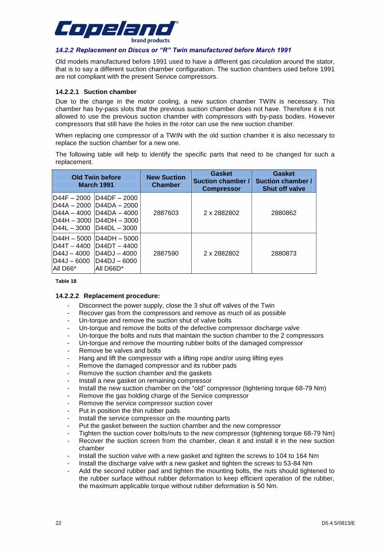
The following table will help to identify the specific parts that need to be changed for such a replacement.
Old Twin before March 1991
New Suction Chamber
Gasket Suction chamber /
Compressor
Gasket Suction chamber /
Shut off valve
D44F – 2000 D44A – 2000 D44A – 4000 D44H – 3000 D44L – 3000
D44DF – 2000 D44DA – 2000 D44DA – 4000 D44DH – 3000 D44DL – 3000
2887603 2 x 2882802 2880862
D44H – 5000 D44T – 4400 D44J – 4000 D44J – 6000 All D66*
D44DH – 5000 D44DT – 4400 D44DJ – 4000 D44DJ – 6000 All D66D*
2887590 2 x 2882802 2880873
Table 18
14.2.2.2 Replacement procedure:
- Disconnect the power supply, close the 3 shut off valves of the Twin - Recover gas from the compressors and remove as much oil as possible - Un-torque and remove the suction shut of valve bolts - Un-torque and remove the bolts of the defective compressor discharge valve - Un-torque the bolts and nuts that maintain the suction chamber to the 2 compressors - Un-torque and remove the mounting rubber bolts of the damaged compressor - Remove be valves and bolts - Hang and lift the compressor with a lifting rope and/or using lifting eyes - Remove the damaged compressor and its rubber pads - Remove the suction chamber and the gaskets - Install a new gasket on remaining compressor - Install the new suction chamber on the “old” compressor (tightening torque 68-79 Nm) - Remove the gas holding charge of the Service compressor - Remove the service compressor suction cover - Put in position the thin rubber pads - Install the service compressor on the mounting parts - Put the gasket between the suction chamber and the new compressor - Tighten the suction cover bolts/nuts to the new compressor (tightening torque 68-79 Nm) - Recover the suction screen from the chamber, clean it and install it in the new suction
chamber - Install the suction valve with a new gasket and tighten the screws to 104 to 164 Nm - Install the discharge valve with a new gasket and tighten the screws to 53-84 Nm - Add the second rubber pad and tighten the mounting bolts, the nuts should tightened to
the rubber surface without rubber deformation to keep efficient operation of the rubber, the maximum applicable torque without rubber deformation is 50 Nm.
Emerson Climate Technologies - European Headquarters - Pascalstrasse 65 - 52076 Aachen, GermanyPhone: +49 (0) 2408 929 0 - Fax: +49 (0) 2408 929 570 - Internet: www.emersonclimate.eu
The Emerson Climate Technologies logo is a trademark and service mark of Emerson Electric Co. Emerson Climate Technologies Inc. is a subsidiary of Emerson Electric Co.Copeland is a registered trademark and Copeland Scroll is a tr ademark of Emerson Climate Technologies Inc.. All other trademark s are property of their respective owners.Information contained in this brochure is subject to change without notifi cation.
© 2011 Emerson Climate Technologies, Inc.
For more details, see www.emersonclimate.eu
BENELUXDeltakade 7NL-5928 PX VenloTel. +31 77 324 02 34Fax +31 77 324 02 [email protected]
UK & IRELANDUnit 17, Theale Lakes Business ParkReading, Berks RG7 4GB Tel: +44 1189 83 80 00Fax: +44 1189 83 80 [email protected]
BALKANSelska cesta 93HR-10 000 ZagrebTel. +385 1 560 38 75Fax +385 1 560 38 [email protected]
GERMANY, AUSTRIA & SWITZERLANDSenefelder Str. 3DE-63477 MaintalTel. +49 6109 605 90Fax +49 6109 60 59 [email protected]
SWEDEN, DENMARK, NORWAY & FINLANDPascalstr. 65DE-52076 AachenTel. +49 2408 929 0Fax +49 2408 92 95 [email protected]
UKRAINETurgenevskaya Str. 15, o�ce 33 UA-01054, KievTel. +38 - 44 - 4 92 99 24Fax. +38 - 44 - 4 92 99 [email protected]
FRANCE, GREECE & MAGHREB8, Allée du Moulin BergerFR-69130 Ecully CédexTel. +33 4 78 66 85 70Fax +33 4 78 66 85 [email protected]
EASTERN EUROPE & TURKEYPascalstr. 65DE-52076 AachenTel. +49 2408 929 0Fax +49 2408 929 [email protected]
ROMANIA
Tel. +40 - 364 - 73 11 72Fax. +40 - 364 - 73 12 [email protected]
ITALYVia Ramazzotti, 26IT-21047 Saronno (VA)Tel. +39 02 96 17 81Fax +39 02 96 17 88 [email protected]
POLANDSzturmowa 2PL-02678 WarsawTel. +48 22 458 92 05Fax +48 22 458 92 [email protected]
MIDDLE EAST & AFRICAPO Box 26382Jebel Ali Free Zone - South, Dubai - UAETel. +971 4 811 81 00Fax +971 4 886 54 [email protected]
SPAIN & PORTUGALC/ LLull, 321 (Edifici CINC)ES-08019 BarcelonaTel. +34 93 412 37 52Fax +34 93 412 42 [email protected]
RUSSIA & CISLetnikovskaya 10, Bld. 2, fl oor 5RU-115114 MoscowTel. +7 495 981 98 11Fax +7 495 981 98 [email protected]
D5.
4.5/
0813
/E